gen write up
TRANSCRIPT
8/8/2019 Gen Write Up
http://slidepdf.com/reader/full/gen-write-up 1/11
MRTG POWER DIAGNOSTIC TESTS PVT LTD.
AN ISO 9001:2008
CERTIFIED COMPANY
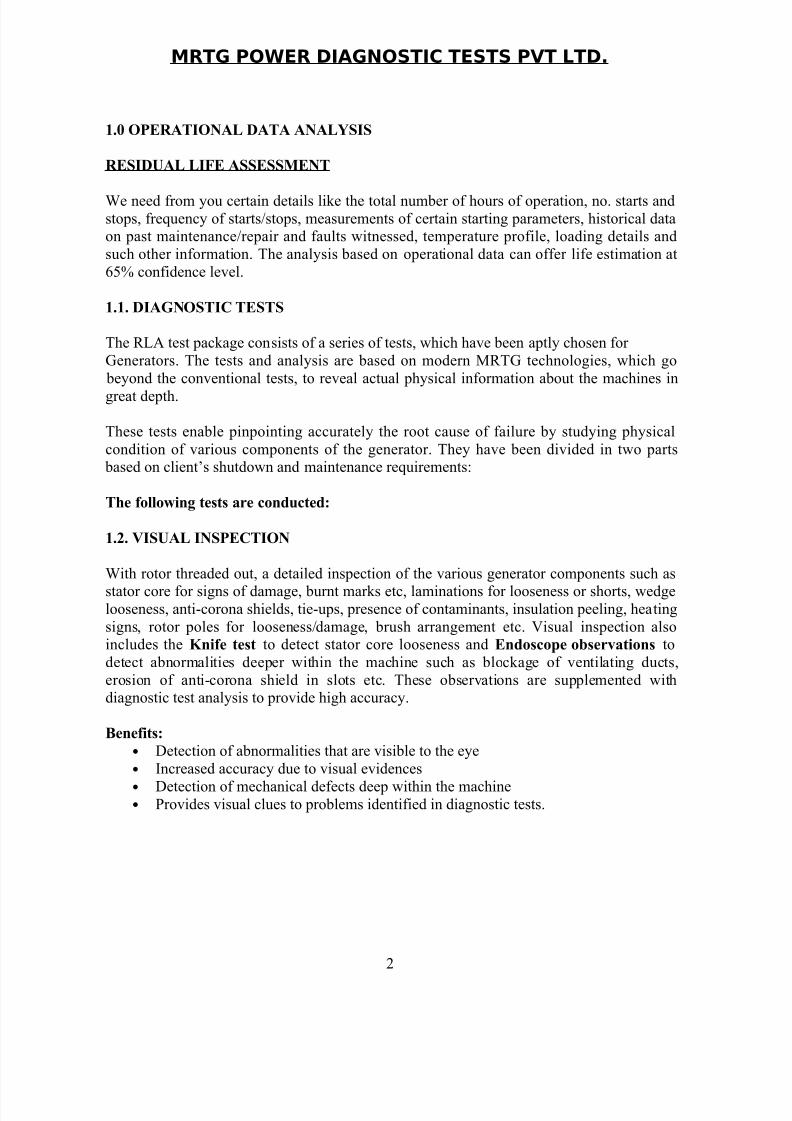
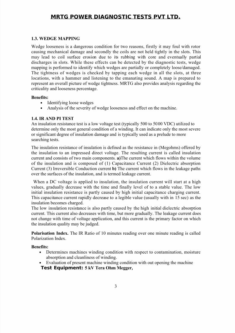
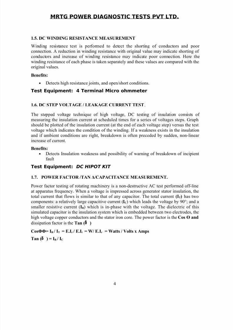
Condition Assessment & Diagnostic
Field Testing of Rotating Machines
MRTG Power Diagnostic Tests Pvt.Ltd.
FLAT No: 202, Sri Sai Towers,
Ravindranagar, HABSIGUDA,
HYDERABAD – 500007, ANDHRA PRADESH,
INDIA.
Tel: +91-40-27156436
Fax: +91-40-27178957
MobileNos;09440239277,
E-mail: [email protected]
E-mail; [email protected]
Web: www.tgdiagnostic.com
1
8/8/2019 Gen Write Up
http://slidepdf.com/reader/full/gen-write-up 2/11
MRTG POWER DIAGNOSTIC TESTS PVT LTD.
1.0 OPERATIONAL DATA ANALYSIS
RESIDUAL LIFE ASSESSMENT
We need from you certain details like the total number of hours of operation, no. starts andstops, frequency of starts/stops, measurements of certain starting parameters, historical dataon past maintenance/repair and faults witnessed, temperature profile, loading details and
such other information. The analysis based on operational data can offer life estimation at
65% confidence level.
1.1. DIAGNOSTIC TESTS
The RLA test package consists of a series of tests, which have been aptly chosen for
Generators. The tests and analysis are based on modern MRTG technologies, which go
beyond the conventional tests, to reveal actual physical information about the machines in
great depth.
These tests enable pinpointing accurately the root cause of failure by studying physical
condition of various components of the generator. They have been divided in two parts based on client’s shutdown and maintenance requirements:
The following tests are conducted:
1.2. VISUAL INSPECTION
With rotor threaded out, a detailed inspection of the various generator components such as
stator core for signs of damage, burnt marks etc, laminations for looseness or shorts, wedgelooseness, anti-corona shields, tie-ups, presence of contaminants, insulation peeling, heating
signs, rotor poles for looseness/damage, brush arrangement etc. Visual inspection alsoincludes the Knife test to detect stator core looseness and Endoscope observations to
detect abnormalities deeper within the machine such as blockage of ventilating ducts,
erosion of anti-corona shield in slots etc. These observations are supplemented withdiagnostic test analysis to provide high accuracy.
Benefits:
• Detection of abnormalities that are visible to the eye
• Increased accuracy due to visual evidences
• Detection of mechanical defects deep within the machine• Provides visual clues to problems identified in diagnostic tests.
2
8/8/2019 Gen Write Up
http://slidepdf.com/reader/full/gen-write-up 3/11
MRTG POWER DIAGNOSTIC TESTS PVT LTD.
1.3. WEDGE MAPPING
Wedge looseness is a dangerous condition for two reasons, firstly it may foul with rotor causing mechanical damage and secondly the coils are not held tightly in the slots. This
may lead to coil surface erosion due to its rubbing with core and eventually partialdischarges in slots. While these effects can be detected by the diagnostic tests, wedgemapping is performed to identify which wedges are partially or completely loose/damaged.
The tightness of wedges is checked by tapping each wedge in all the slots, at three
locations, with a hammer and listening to the emanating sound. A map is prepared to
represent an overall picture of wedge tightness. MRTG also provides analysis regarding thecriticality and looseness percentage.
Benefits:
• Identifying loose wedges
• Analysis of the severity of wedge looseness and effect on the machine.
1.4. IR AND PI TEST
An insulation resistance test is a low voltage test (typically 500 to 5000 VDC) utilized to
determine only the most general condition of a winding. It can indicate only the most severe
or significant degree of insulation damage and is typically used as a prelude to moresearching tests.
The insulation resistance of insulation is defined as the resistance in (Megohms) offered by
the insulation to an impressed direct voltage. The resulting current is called insulationcurrent and consists of two main components. a)The current which flows within the volume
of the insulation and is composed of (1) Capacitance Current (2) Dielectric absorption
Current (3) Irreversible Conduction current b) The current which flows in the leakage paths
over the surfaces of the insulation, and is termed leakage current. When a DC voltage is applied to insulation, the insulation current will start at a high
values, gradually decrease with the time and finally level of to a stable value. The lowinitial insulation resistance is partly caused by high initial capacitance charging current.
This capacitance current rapidly decrease to a legible value (usually with in 15 sec) as the
insulation becomes charged.The low insulation resistance is also partly caused by the high initial dielectric absorption
current. This current also decreases with time, but more gradually. The leakage current does
not change with time of voltage application, and this current is the primary factor on whichthe insulation quality may be judged.
Polarisation Index. The IR Ratio of 10 minutes reading over one minute reading is calledPolarization Index.
Benefits:
• Determines machines winding condition with respect to contamination, moisture
absorption and cleanliness of winding.• Evaluation of present machine winding condition with out opening the machine
Test Equipment: 5 kV Tera Ohm Megger,
3
8/8/2019 Gen Write Up
http://slidepdf.com/reader/full/gen-write-up 4/11
MRTG POWER DIAGNOSTIC TESTS PVT LTD.
1.5. DC WINDING RESISTANCE MEASUREMENT
Winding resistance test is performed to detect the shorting of conductors and poor connection. A reduction in winding resistance with original value may indicate shorting of
conductors and increase of winding resistance may indicate poor connection. Here thewinding resistance of each phase is taken separately and these values are compared with theoriginal values.
Benefits:
• Detects high resistance joints, and open/short conditions.
Test Equipment: 4 Terminal Micro ohmmeter
1.6. DC STEP VOLTAGE / LEAKAGE CURRENT TEST.
The stepped voltage technique of high voltage, DC testing of insulation consists of measuring the insulation current at scheduled times for a series of voltages steps. Graphshould be plotted of the insulation current (at the end of each voltage step) versus the test
voltage which indicates the condition of the winding. If a weakness exists in the insulation
and if ambient conditions are right, breakdown is often preceded by sudden, non-linear
increase of current.
Benefits:
• Detects Insulation weakness and possibility of warning of breakdown of incipientfault
Test Equipment: DC HIPOT KIT
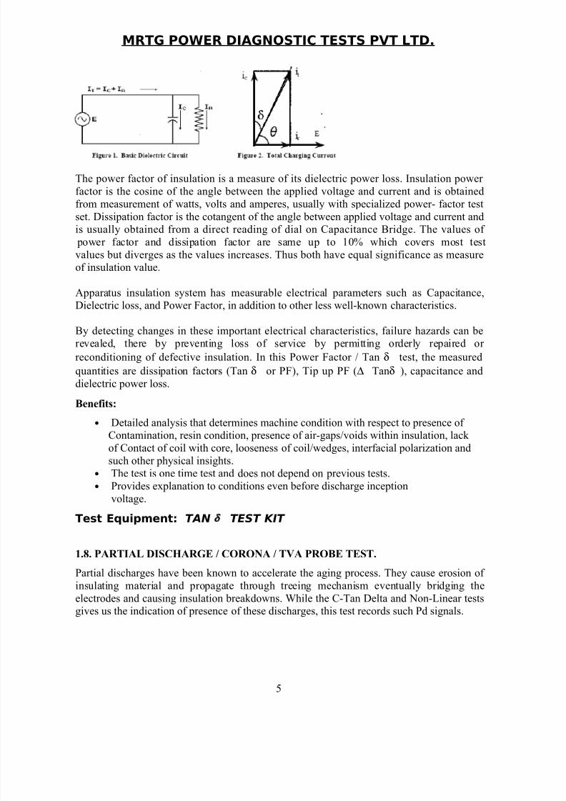
1.7. POWER FACTOR /TAN Δ/CAPACITANCE MEASUREMENT.
Power factor testing of rotating machinery is a non-destructive AC test performed off-line
at apparatus frequency. When a voltage is impressed across generator stator insulation, the
total current that flows is similar to that of any capacitor. The total current (IT) has twocomponents: a relatively large capacitive current (IC) which leads the voltage by 90°; and a
smaller resistive current (IR ) which is in-phase with the voltage. The dielectric of this
simulated capacitor is the insulation system which is embedded between two electrodes, the
high voltage copper conductors and the stator iron core. The power factor is the Cos Ө and
dissipation factor is the Tan (δ )
CosΦΦ= IR / IT = E.Ir / E.It = W/ E.Ir = Watts / Volts x Amps
Tan (δ ) = IR / IC
4
8/8/2019 Gen Write Up
http://slidepdf.com/reader/full/gen-write-up 5/11
MRTG POWER DIAGNOSTIC TESTS PVT LTD.
The power factor of insulation is a measure of its dielectric power loss. Insulation power
factor is the cosine of the angle between the applied voltage and current and is obtained
from measurement of watts, volts and amperes, usually with specialized power- factor test
set. Dissipation factor is the cotangent of the angle between applied voltage and current andis usually obtained from a direct reading of dial on Capacitance Bridge. The values of
power factor and dissipation factor are same up to 10% which covers most test
values but diverges as the values increases. Thus both have equal significance as measureof insulation value.
Apparatus insulation system has measurable electrical parameters such as Capacitance,Dielectric loss, and Power Factor, in addition to other less well-known characteristics.
By detecting changes in these important electrical characteristics, failure hazards can berevealed, there by preventing loss of service by permitting orderly repaired or
reconditioning of defective insulation. In this Power Factor / Tan δ test, the measured
quantities are dissipation factors (Tan δ or PF), Tip up PF (∆ Tanδ ), capacitance and
dielectric power loss.
Benefits:
• Detailed analysis that determines machine condition with respect to presence of Contamination, resin condition, presence of air-gaps/voids within insulation, lack
of Contact of coil with core, looseness of coil/wedges, interfacial polarization and
such other physical insights.• The test is one time test and does not depend on previous tests.
• Provides explanation to conditions even before discharge inception
voltage.
Test Equipment: TAN δ TEST KIT
1.8. PARTIAL DISCHARGE / CORONA / TVA PROBE TEST.
Partial discharges have been known to accelerate the aging process. They cause erosion of
insulating material and propagate through treeing mechanism eventually bridging the
electrodes and causing insulation breakdowns. While the C-Tan Delta and Non-Linear testsgives us the indication of presence of these discharges, this test records such Pd signals.
5
8/8/2019 Gen Write Up
http://slidepdf.com/reader/full/gen-write-up 6/11
MRTG POWER DIAGNOSTIC TESTS PVT LTD.
It was found that synthetic epoxy mica insulated windings were showing high dischargelevels, due to the erosion of the main wall insulation. This was found to be due to the loss
of the corona shields, which comprised a painted graphite coating on the surface of the coils
in contact with the stator iron. The loss of the corona shields was due to the poor adhesion
of the corona materials used, the fit of the coils within the slots, and the bracing of thewindings
The (TVA) probe permits location of partial discharge (PD) since it is sensitive to radiofrequency signals produced by PD. The basic principles of TVA probe, known as the
discharge locating (DL) probe, is very-high-frequency detection using a capacitive sensor
and microprocessor-based signal processing. These features are intended to make the probeeasier to use and less ambiguous in the interpretation of results.
The coupling technique used permits significantly improved spatial resolution of the
discharge source and immunity to radiated electrical interference. Field evaluation of theDL probe has generally been successful, with the results confirming theoretical and
laboratory-based studies of the device
The probe consists basically of a ferrite core, half circular in shape over which has beenwound a number of turns of insulated conductor, the terminations of which are connected to
a meter. When the ferrite probe lead bridges across a stator slot of an energised machine, a
small current will be induced into the turns of the probe if discharges are present, either bydischarging voids within the cell insulation, or discharges that are external to the main wall
insulation.
The combination of the probe, the stator iron and the coils within the slots resembles a
current transformer, the stator coils representing the primary circuit and the head of the probe, the secondary.
In order for the TVA testing to be performed, it is normally a requirement that the rotors are
removed from the stators so that the electromagnetic probe can be inserted into the stator frame. The stator winding is energised voltages up to Line to ground. The probe is moved
along each individual slot and the levels of discharge current are recorded from the peak milli ammeter.
Benefits:
• Determining the type of discharges/location.
• Suggesting maintenance actions to minimize such discharges.
Test Equipment: Corona probe
6
8/8/2019 Gen Write Up
http://slidepdf.com/reader/full/gen-write-up 7/11
MRTG POWER DIAGNOSTIC TESTS PVT LTD.
1.9. ELCID TEST.
Electromagnetic core imperfection detection (ELCID) test is an alternative test to the full
flux test. Around 4% flux will be created in the stator core with the help of a “loop” wound
torodially around the core. A pick-up coil will be used to access the leakage fluxes that bridge adjacent teeth. Fault currents generated at the position hot spots” or shorted
laminations, between the accessed leakage fluxes and the exciting fluxes will be noted, todetect the shorted laminations, using ELCID Evolution specially developed for the purpose.The stator core is made of silicon steel with high permeability and low hysteresis and eddy
current Losses. The sheets are suspended in the stator frame from insulated guide bars.
Stator laminations are coated with synthetic varnish; are stacked and held between sturdysteel clamping plates with non-magnetic pressing fingers which are fastened or welded to
the stator frame. In order to minimize eddy current losses of rotating magnetic flux which
interact with the core is built of thin laminations. Each lamination layer is made of individual segments.
The segments are punched in one operation from electrical sheet steel lamination having
high silicon content and are carefully deburred. The stator laminations are assembled asseparate cage core without the stator frame. The segments are staggered from layer to layer
so that a core of high mechanical strength and uniform permeability to magnetic flux is
obtained. On the outer circumference the segments are stacked on insulated rectangular barswhich hold them in position.
Benefits:
• Identification of core faults such as interlaminar shorts and hot-spots.
• Timely detection of the core defects helps in prevention of earth faults.
Test Equipment:1) Computerized Digital ELCID (Evolution) Instrument
2) Lap top computer 3) Variac; 0 – 240 V, 15 A4) Clamp Meter 5) Multi Meter
7
8/8/2019 Gen Write Up
http://slidepdf.com/reader/full/gen-write-up 8/11
MRTG POWER DIAGNOSTIC TESTS PVT LTD.
1.10. RSO TEST
RSO test is performed to detect faults in rotor windings. The electrical faults in generator
rotors fall into two main categories,1. Faults from the winding to the rotor body (earthfaults) 2. Faults between parts of the winding (inter-turn winding faults).The existence of
the faults will frequently display excessive mechanical vibration and cause serious concern.An RSO test identifies the type of fault.
The technique Recurrent Surge Oscillograph (RSO), is performed to detect faults in rotor
winding. It involves applying a fast fronted step voltage to a winding and examining the
terminal voltage waveform for reflections from shorted turns.
An advantage for the manufacturer is that the test is quick and can be applied at different
stages of coil winding to check integrity. However, the technique is very sensitive; it can
detect turn to turn `shorts' with resistances up to approximately 10 ohms. A healthy rotor winding will have two identical traces, which are super imposed. A rotor with a fault will
have different traces and the position of the faults may be deduced by scaling in the time
domain
Benefits:
• Effective detection of rotor winding interturn shorts, ground faults and high
resistance Joints
Test Equipment: 1. Rotor Reflectometer 2. Digital Oscilloscope
1.11. IMPEDANCE MEASUREMENT ON ROTOR WINDING.
Shorted turns in the rotor winding can be detected by periodic measurement of rotor
impedance using AC power supply. These tests should ideally be performed while the
machine is running at synchronous speed. Because shorted turns may only exists whencentrifugal forces are acting on the turn conductors. When the machine is shut down, there
may not be any contact, or the fault resistance measurement.
The induced backward current in a single shorted turn, which opposes the magnetic motive
force (mmf) of the entire coil, resulting in a significant reduction in the reactance.
This technique is particularly effective in salient pole rotors, where one short circuited turneliminates the reactance of the complete pole. There is a sudden change in impedance when
a turn is shorted during run-up or run down. A sudden change of more 5% is needed to
verify for shorted turns.
A normal winding will exhibit, reduction in impedance up to 10% between stand still andoperating conditions due to effect of eddy currents on the rotor. The test can only be performed if the field winding is accessible through collector rings because ac power
should be applied while the machine is running. The power supply should be ungrounded.[ Test Equipment: 1) Dimmer stat, 0-230 V, 28 Amp
2) Voltmeter 3) Clamp Meter
8
8/8/2019 Gen Write Up
http://slidepdf.com/reader/full/gen-write-up 9/11
MRTG POWER DIAGNOSTIC TESTS PVT LTD.
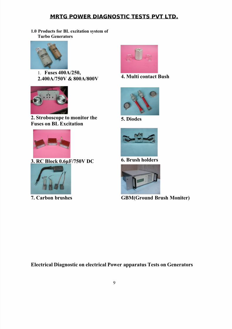
1.0 Products for BL excitation system of
Turbo Generators
1. Fuses 400A/250,
2.400A/750V & 800A/800V
2. Stroboscope to monitor the
Fuses on BL Excitation
3. RC Block 0.6μF/750V DC
4. Multi contact Bush
5. Diodes
6. Brush holders
7. Carbon brushes GBM(Ground Brush Moniter)
Electrical Diagnostic on electrical Power apparatus Tests on Generators
9
8/8/2019 Gen Write Up
http://slidepdf.com/reader/full/gen-write-up 10/11
MRTG POWER DIAGNOSTIC TESTS PVT LTD.
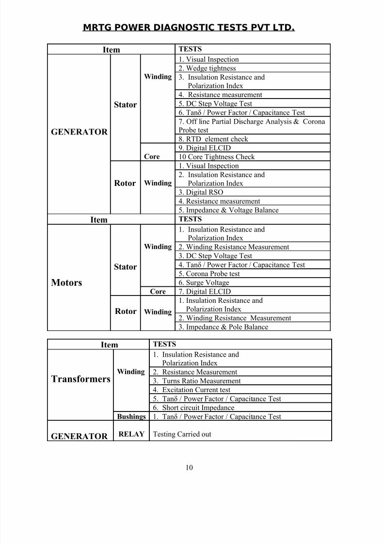
Item TESTS
GENERATOR
Stator
Winding
1. Visual Inspection
2. Wedge tightness
3. Insulation Resistance and
Polarization Index
4. Resistance measurement5. DC Step Voltage Test
6. Tanδ / Power Factor / Capacitance Test
7. Off line Partial Discharge Analysis & CoronaProbe test
8. RTD element check
Core
9. Digital ELCID
10 Core Tightness Check
Rotor Winding
1. Visual Inspection
2. Insulation Resistance and
Polarization Index
3. Digital RSO4. Resistance measurement
5. Impedance & Voltage Balance
Item TESTS
Motors
Stator
Winding
1. Insulation Resistance andPolarization Index
2. Winding Resistance Measurement
3. DC Step Voltage Test
4. Tanδ / Power Factor / Capacitance Test
5. Corona Probe test
6. Surge VoltageCore 7. Digital ELCID
Rotor Winding
1. Insulation Resistance and
Polarization Index
2. Winding Resistance Measurement
3. Impedance & Pole Balance
Item TESTS
Transformers
Winding
1. Insulation Resistance andPolarization Index
2. Resistance Measurement
3. Turns Ratio Measurement4. Excitation Current test
5. Tanδ / Power Factor / Capacitance Test
6. Short circuit Impedance
Bushings 1. Tanδ / Power Factor / Capacitance Test
GENERATOR RELAY Testing Carried out
10
8/8/2019 Gen Write Up
http://slidepdf.com/reader/full/gen-write-up 11/11
MRTG POWER DIAGNOSTIC TESTS PVT LTD.
11