ge24021 couv en - legrand · cat. no. 365 82 is fitted inside the door 6. door equipotential link...
TRANSCRIPT

XL3400Distribution enclosures
WORKSHOP SPECIFICATIONS

1ContentsTHE XL3 400 RANGE
Characteristics and selection tables 2
ASSEMBLING THE ENCLOSURES
A - XL3 400 metal enclosures 8
B - XL3 400 insulated enclosures 16
FITTING THE DISTRIBUTION SYSTEMS
A - Optimised distribution 19
B - Standard distribution at the back of the enclosure 24
C - Standard distribution in wiring sleeves 30
D - Supply busbars, terminal blocks, distribution terminals and modular distribution blocks 32
FITTING DEVICES AND EQUIPMENT
A - Principle for defining the required space 34
B - Capacity of the enclosures 36
C - Positioning the fixing devices 36
D - Fitting devices on plates 38
E - Fitting devices on rails 40
F - Fitting devices in wiring sleeves 41
G - French tariff connection plates 42
H - Equipment on doors and side panels 46
WIRING AND CONNECTION
A - Wiring 48
B - Protective conductors 50
C - Terminal blocks 52
D - Fitting supports for terminal blocks on plates 53
E - Inserting the cables 54
HANDLING AND ON-SITE INSTALLATION
A - Handling and transport 56
B - Fixing the enclosures 57
APPENDICES
Dimensions 58
With its extensive ranges, the Legrand offer meets your quality
standards and provides real freedom and simplicity of installation
together with acknowledged reliability.
With the XL3 400 enclosures, Legrand has optimised the concept of
product integration. Whichever enclosure you choose, and whatever your
preferred way of working and the technical demands of your
installations, you will find the answer to your requirements with XL3 400.
XL3 400 incorporates numerous practical innovations for quick, safe
assembly:
■ Metal or insulated enclosures
■ Products delivered dismantled for full wiring accessibility
■ Optimised equipment for easy installation
■ Sealable faceplates with metal 4 turn fastening and handles
■ All you need is a 10 mm spanner and a screwdriver for assembling the
side panels, rails, plates and faceplates
■ Fast horizontal or vertical joining using 4 screws/nuts
■ Re-usable cardboard packaging for increased protection when
handling

32
The XL3 400 RANGE
X L 3 4 0 0 E N C L O S U R E S
Externalheight (mm)
1 900
1 600
1 500
1 200
1 050
900
750
600
Cat. No. 201 03 201 04 201 05 201 06 201 07 201 08 201 18 201 19
Height withfaceplate (mm)
550 700 850 1 000 1 150 1 450 1 450 1 750
202 53 202 54 202 55 202 56 202 57 202 58 202 58 202 59
202 63 202 64 202 65 202 66 202 67 202 68 202 68 202 69
202 73 202 74 202 75 202 76 202 77 202 78 202 78 202 79
202 83 202 84 202 85 202 86 202 87 202 88 202 88 202 89
201 23 201 24 201 25 201 26 201 27 201 28 201 38 201 39
201 63 201 64 201 65 201 66 201 67 201 68 201 68 201 69
CHARACTERISTICS
XL3 400 can be used to create customised
enclosures for all your environments.
■ IP 30 to IP 55
■ IK 04 to IK 08
■ Class I and class II
■ Fire resistance: 750°/5 s (IEC 60695-2)
for installation in public buildings
■ Short time withstand current Icw: 25 kA 1 s
■ 24 modules per row
■ Take devices up to 400 A
■ Choice of distribution: standard or optimised
(XL-Part 250 active backplate, 250 A row distribution
block, etc.)
■ Joinable (left and/or right) and extendable wiring
sleeves: Lexic, DPX and distribution devices
■ Colour: RAL 7035
■ Conform to standard IEC 60439-1
IP 30-40-43 METAL ENCLOSURESDepth: 175 mm - External width: 575 mm (see dimensions on page 58)
Roundeddoor
Flatdoor
Wiring sleeve
Solid door for wiring sleeve
solid
glass
solid
glass
Wal l-mount ing enclosures Floor-standingenclosures

54
The XL3 400 range (continued)
X L 3 4 0 0 E N C L O S U R E S
ONE-PIECE IP 55 ENCLOSURESDepth: 215 mm - External width: 650 mm (see dimensions on page ##)
IP 30-40-43 INSULATED ENCLOSURESDepth: 175 mm - External width: 575 mm (see dimensions on page 58)
Externalheight (mm)
1 200
1 050
900
750
600
Cat. No. 201 53 201 54 201 55 201 56 201 57
Height withfaceplate
(mm)
550 700 850 1 000 1 150
202 53 202 54 202 55 202 56 202 57
202 63 202 64 202 65 202 66 202 67
202 73 202 74 202 75 202 76 202 77
202 83 202 84 202 85 202 86 202 87
201 73 201 74 201 75 201 76 201 77
201 63 201 64 201 65 201 66 201 67
Roundeddoor
Flatdoor
Wiring sleeve
Solid door forwiring sleeve
solid
glass
solid
glass
Externalheight(mm)
1115
915
715
515
Cat. No. 201 82 201 83 201 84 201 85
Height withfaceplate
(mm)
400 600 800 1 000
Insulated enclosureMetal floor-standing enclosure andwiring sleeve
Metal wall-mountingenclosure

76
The XL3 400 range (continued)
X L 3 4 0 0 E N C L O S U R E S
metal insulated IP 55
External fixing lugs 201 00 201 50
Horizontal joining strengthening bars 201 51
Plinths for enclosures 201 10 201 10
Plinths for wiring sleeves 201 12 201 12
IP 43 kit 201 30 201 30
Universal plate for enclosures H: 200 mm
202 41 202 41 202 41
Universal plate for enclosures H: 300 mm
202 42 202 42 202 42
Universal plate for wiring sleeve H: 300 mm 202 43 202 43
Universal rail W: 515 mm 202 04 202 04 202 04
Horizontal partitioning divider 201 90 201 90 201 90
Adjustable cable entry plate 201 20
Knockout cable entry plate(*) 201 21 201 71
Cabstop cable entry plate 364 99
Isolating supports 200 90 200 90 200 90
Clip-nuts (20) 200 92 200 92 200 92
M6 screw (50) 200 91 200 91 200 91
Aerosol paint spray RAL 7035 200 98 200 98 200 98
ACCESSORIESAccessories for doors
Key barrel type 405 202 91
Key barrel type 455 202 92
Key barrel type 1242E 202 93
Key barrel type 2433A 202 94
Double bar knockout 202 96
Equipotential link conductor 373 85
Flexible plastic document holder 097 99
Rigid plastic document holder 365 82
Accessories for faceplates
24-module smooth adjustable blanking plate 200 51
8-module separable blanking plate 016 65
Adhesive label-holder 203 99
Wiring accessories
Lina 25 ducting fixing support 201 70
Horizontal wire guides 200 94
Vertical wire guides 201 93
Cable fixing for enclosures 201 35
Cable fixing for wiring sleeve (except for IP 55) 201 37
DLP finishing strip 201 60
* Availability: June 2005

98
Assembling the enclosures
X L 3 4 0 0 E N C L O S U R E S
XL3 400 METAL enclosures
Metal enclosures and wiring sleeves are supplied dismantled.
Each enclosure consists of a back, two functional uprights joined
to the back, four corner pieces, four side panels and a cable entry
plate. Enclosures more than 1500 mm high are supplied with a
plinth.
1. Assembling the back and the cornersA single method for mounting enclosures
and wiring sleeves.
2. Fitting the side panelsInsert the side panels in the top of the corner
runners then slide downwards. Lock the side
panels with four M6 x 10 screws.
All components aredelivered dismantled, for minimumdimensions
Insert thecorners in thefunctionaluprights…
… then attachwith a single
M6 x 10 screw
All the enclosures are supplied with anadjustable insulated cable entry plate
Standardised screws: all you need is a screwdriver and a 10 mm spanner
One-piece cardboard packaging, can bere-used for thedelivery of theassembled enclosureto the site
Slide the side panels steadily in the corner runners until they are inserted in the back
Side panel with cut-out forfitting cable entry platesand for feeding throughwiring when joiningenclosures
M6 screws
The new Legrand XL3 400 range of enclosures is available in 3 versions tomeet the needs of all applications: metal, insulated and one-piece IP 55enclosures. They are quick and easy to install, and suitable for all typesof joining, optimising compactness, space for wiring and strength. The XL3 400 has a particularly high-quality finish: with faceplate, with orwithout door.
+
+
The functional uprightsintegrated at the back ofXL3 400 enclosures areused for quick and reliablefixing of all equipment
Two fixing heights
A

1110
Assembling the enclosures (continued)
X L 3 4 0 0 E N C L O S U R E S
Care must betaken to usethe correctholes
Horizontal and vertical joining can be usedtogether
Attach the 2 sides of the plinth using thefour M6 screws and four nuts provided
The front and rear covers of the plinthare attached using 4 self-tappingscrews
The plinths can be placed on top of one another for better spreading of the cables
Release the 2 linking ringsfrom the connecting rodsand the mechanism
Unscrew the 2 screws fixingthe handle and themechanism
2 - Rotate
3. Joining enclosuresRemove the seals from the corner pieces and join the
enclosures using the four M6 screws and four nuts
provided.
5. Fitting the doorsThe direction in which the door opens determines the sides on
which the hinges and latches are fitted.
Enclosures ≥ 1,500 mm high
To fit the doors, enclosures h ≥ 1500 mm must be fitted with 3
hinges on one side and 2 latches on the other.
4. Fitting the plinthAs for joining enclosures, the corner piece seals must be
removed before fitting the plinths.
The door is opened in 2 stages:
1 - Disengage
+
+
+Corner piece
Plinth
To reverse the way the door opens, fit the hinges on the left
hand side and the latches on the right hand side. The door
itself will be turned round 180 degrees. The mechanism
which operates the connecting rods must also be dismantled
and turned round 180 degrees.
The doors are supplied to be fitted to “open to the right”
Reverse the connecting rods, then reassemble the
mechanism in the same way.
[2] [1]
Joining with no accessories
Fully integrated handle
Fitting the sealssupplied with thedoors ensuresIP 30 protection

1312
Assembling the enclosures (continued)
X L 3 4 0 0 E N C L O S U R E S
Combine the adaptor casingand barrel assembly with theblack adaptor
Insert the pin in the notchtowards the front
Insert theassembled barrelin the body of the handle
Refit thehandle on itssupport
It is essential to fit the metal bracket so that the handle locks correctly
Push in the2 black clipsto remove theblanking plate
Combine theadaptor casing andbarrel assemblywith the aluminiumcoloured adaptor
Insert theassembled barrelin the body of thehandle
Enclosures < 1,500 mm high
Small handle(enclosures H < 1,500 mm)
Once the handle has been dismantled (M6 screw) the
blanking plate is automatically released.
To fit the doors,enclosuresh < 1500 mm mustbe fitted with2 hinges on oneside and one doorrelease on the other
+
Self-adhesive document holderCat. No. 365 82 is fitted inside thedoor
6. Door equipotential linkThe doors have studs for connecting equipotential link
conductor Cat. No. 373 85.
Make a notch in the plasticcover for the conductor to passbehind the hinge
ConductorCat. No. 373 84clips directly onto the faceplatesupport inside theenclosure
When the plastic cover isremoved, up to 4 conductorscan be inserted in theenclosure (see page 47)
7. Fitting the key barrelsThe method differs according to the type of handle used.
Large handle(enclosures H ≥ 1,500 mm)
1514
Assembling the enclosures (continued)
X L 3 4 0 0 E N C L O S U R E S
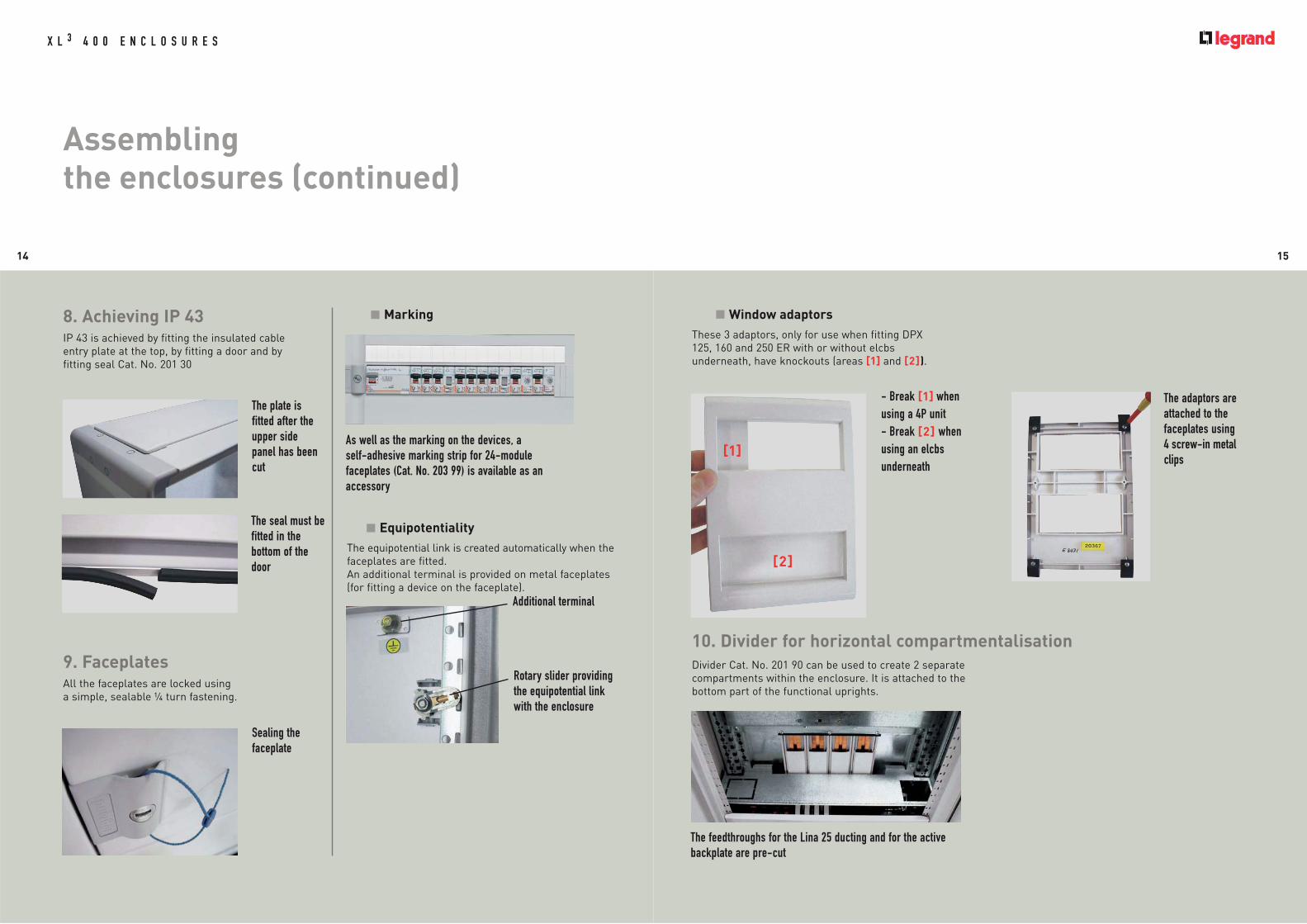
Sealing thefaceplate
The adaptors areattached to the faceplates using 4 screw-in metalclips
9. FaceplatesAll the faceplates are locked using
a simple, sealable 4 turn fastening.
Marking
Equipotentiality
The equipotential link is created automatically when the
faceplates are fitted.
An additional terminal is provided on metal faceplates
(for fitting a device on the faceplate).
Window adaptors
These 3 adaptors, only for use when fitting DPX
125, 160 and 250 ER with or without elcbs
underneath, have knockouts (areas [1] and [2]).
As well as the marking on the devices, a self-adhesive marking strip for 24-modulefaceplates (Cat. No. 203 99) is available as anaccessory
Additional terminal
Rotary slider providingthe equipotential linkwith the enclosure
- Break [1] when using a 4P unit- Break [2] whenusing an elcbsunderneath
[1]
[2]
The plate isfitted after theupper sidepanel has beencut
The seal must befitted in thebottom of thedoor
8. Achieving IP 43IP 43 is achieved by fitting the insulated cable
entry plate at the top, by fitting a door and by
fitting seal Cat. No. 201 30
10. Divider for horizontal compartmentalisation
Divider Cat. No. 201 90 can be used to create 2 separate
compartments within the enclosure. It is attached to the
bottom part of the functional uprights.
The feedthroughs for the Lina 25 ducting and for the activebackplate are pre-cut

17
3 - Fitting the doorsFitting and reversing the doors is in all respects
identical to metal enclosures (see page 11).
Fitting the seal Cat. No. 201 30/32 on the door ensures
IP 43 protection (see page 14).
4 - FaceplatesInsulated faceplates, like metal faceplates have a
sealable 4 turn fastening.
The shape of thefaceplates isspecially designedfor ease ofhandling
+
To comply withclass II, replace theplastic covers thatare supplied toinsulate the fixingscrews
5 - Complying with class II
The blanking plates for the unused hingepositions are held in place by a screw, whichcan be inserted with no need for any tool
16
Assembling the enclosures (continued)
X L 3 4 0 0 E N C L O S U R E S
XL3 400 INSULATED ENCLOSURESLike metal enclosures, XL3 400 insulated enclosures
and wiring sleeves are supplied dismantled in
reusable packaging.
Each enclosure consists of a back, four corner pieces,
four side panels and a faceplate frame in four
separate parts.
The metal back, joined to the functional uprights,
provides optimum rigidity. Inside it is fitted with an
insulated back which can take C-section busbars
Cat.No. 373 30 and supports Cat. No. 373 31/32 to create
an XL-Part 400 active backplate. It is insulated at the
back to ensure it is class II.
All the other parts of the enclosure are made of
insulated plastic material.
1 - Assembling the enclosures and wiring sleevesAs with metal enclosures, each corner piece is
inserted in the functional uprights and attached using
an M6 screw (see page 9).
The side panels are installed by sliding them in the
corner runners. They are held in place by the faceplate
frame.
2 - Joining enclosuresEnclosures and wiring sleeves can be joined horizontally
or vertically in the same way as for metal enclosures
(see page 10). For the cable feedthroughs, simply do not
fit the side panels.
Each side of theframe is attachedseparately to thecorner pieces by2 Phillips screws
Joining anenclosure and awiring sleeve
The backs of theinsulatedenclosures areready to take C-sectionbusbars to createan activebackplate
B

1918
Fitting the distribution systems
X L 3 4 0 0 E N C L O S U R E S
XL3 400 gives users the freedom to organise the distribution.
■ XL-Part “optimised” distribution:
designed to optimise the volume of XL3 400 enclosures, it uses C-section busbars forintegration in a special insulated back (XL-Part 400 active backplate) and 250 A rowdistribution blocks
■ “Standard” distribution using flat busbars:
- Vertical at the back of the enclosure, can be used with the Lexiclic distribution block
- Horizontal at the back of the enclosure
- Vertical stepped in wiring sleeves
“OPTIMISED” DISTRIBUTION
1. Fitting the XL-Part 400 activebackplate
Insulated enclosures are prefitted with an insulated back.
Metal enclosures can be fitted with an insulated back as an option
(Cat. No. 201 88/89). An active backplate is created by equipping the
insulated back with C-section busbars held in place by supports.
Lug support Cat. No. 373 32
Insulated cover Cat. No. 373 33 for IPxxB protection
C-section busbar Cat. No. 373 30
Insulated activebackplate Cat. No. 201 88/89
Supports Cat. No. 373 31
Maximum distance “D” between the supports according to
peak current Ipk
Preparation of the equipment to create optimiseddistribution in an enclosure h = 1,900 mm
In
(A)
Ipk
(kÂ)
D
(mm)
373 30 400 373 31
17 1800
26 1000
40 800
50 600
Distribution solutions up to 400 A
Optimised distribution Standard distribution
in enclosure in enclosure in wiring sleeve
XL3 400metal IP 43
XL-Part 400 active backplate:- insulated back Cat. No. 201 88/89- C-section busbars Cat. No. 373 30- supports Cat. No. 373 31- lug support Cat. No. 373 32
Row distribution block 250 A Cat. No. 373 36/37
XL3 400insulated
IP 43
XL-Part 400 active backplate:- C-section busbars Cat. No. 373 30- supports Cat. No. 373 31- lug support Cat. No. 373 32
Row distribution block 250 A Cat. No. 373 36/37
XL3 400 IP 55
Set of vertical busbars- support Cat. No. 373 15 - flat bars Cat. No. 374 18/19/34
Row distribution block Lexiclic Cat. No. 373 16/17/18
Set of vertical busbars- support Cat. No. 373 15 - flat bars Cat.No. 374 18/19/34
Row distribution block Lexiclic Cat. No. 373 16/17/18
Distribution block 400 ACat. No. 373 08
Set of vertical busbars- support Cat. No. 373 10 - flat bars Cat. No. 374 18/19
vertical horizontal
A

2120
Fitting the distribution systems (continued)
X L 3 4 0 0 E N C L O S U R E S
Cut the C-section busbars to the requiredlength then start byfixing lug support Cat. No. 373 32 at thebottom of the insulatedbackplate
Then fit a supportCat. No. 373 31 at thetop of the insulatedbackplate
You can then install theplate to take the powersupply device for the busbar and the intermediatesupports Cat. No. 373 31(the number used dependson the peak short-circuitcurrent value, see table onpage 19)
Row distribution block Cat. No. 373 36 is connected directlyon the C-section busbars of the active backplate
Inserting the hammer screw for connection onthe vertical busbar. Once the nut has beentightened, it is advisable to protect it with theinsulated cover provided
Fitting a support base for DPX 125 on row distribution blockCat. No. 373 36. It is fixed using 4 screws (one screw oneach bar)
The DPX 125 isfitted with itsusual fixing screws
+
The linking kits are used for directconnection of the main device:Cat. No. 373 34: DPX 250Cat. No. 373 35: DPX 250 + elcbsCat. No. 373 38: DPX 630
Installing the terminal shieldsupplied with thebase to maintainthe IP protection
2. Fitting the 250 A row distribution blockThe row distribution block takes the device support bases. It is supplied either
directly via the active backplate (Cat. No. 373 36), or indirectly via the head of row
device (Cat. No. 373 37).
Direct power supply via the activebackplate
All the devices in the row are supplied directly via
distribution block Cat. No. 373 36.
These kits can be fitted with IP xxB protection(Cat. No. 373 70/71/72)
Current transformers Cat. No. 046 98/99 forDPX 250/400 are fitted directly on the linkingkits

2322
Fitting the distribution systems (continued)
X L 3 4 0 0 E N C L O S U R E S
3. Fitting the XL-Part 125 rowdistribution blockThe XL-Part 125 four pole distribution block clips onto
fixing device Cat. No. 202 00 under a 200 mm faceplate.
- Direct power supply via the terminals of one of the
devices up to 63 A
- Power supply via a connection module Cat. No. 045 05
(35 mm2 cage terminal up to 125 A (central power
supply) and 80 A (side power supply).
The “Plug-in” connection modules are used for
automatic connection of all Lexic MCBs, 1 module per
pole, up to 63 A. Wired connection modules are used
to connect all Lexic 1P + N devices, up to 32 A.
4. Fitting the XL-Part 100 row distribution blockThe XL-Part 100 distribution block is available in 2
versions: 3P or 4P. It clips onto rail Cat. No. 202 00.
It supplies all Lexic 3 or 4 pole MCBs up to 63 A
directly by a “Plug-in” system.
Clipping theXL-Part 125distribution blockonto aluminiumprofile rail Cat. No. 202 00
A dummy strip that can be cut to size can be plugged into theunused terminals to provide IP xxB protection
XL-Part 125 allows 4 pole, 3 pole, 2 pole, phase/neutral andsingle pole devices to be mixed on the same row
The distribution block can be sawn into partial rows
The 4 copperlinks are theninserted in thebottom of thebase
If the DPX has alateral elcbs, it isthe base of theelcbs that suppliesthe distribution block via the 4insulated links
Clipping the linksin place
Indirect power supply via the main device
With distribution block Cat. No. 373 37, it is the DPX
that supplies the row distribution block Cat. No. 373 37

2524
Fitting the distribution systems (continued)
X L 3 4 0 0 E N C L O S U R E S
32 x 5
32 x 5
“STANDARD” DISTRIBUTION AT THE BACK OF THE ENCLOSURE
Standard distribution at the back of the enclosure can be created
vertically with busbar supports Cat. No. 373 15, with the addition of
Lexiclic if required, or horizontally with distribution block
Cat. No. 373 08.
1. Fitting the vertical busbarSupport Cat. No. 373 15 is used to fit the busbar
at the back of enclosures Maximum distance “D” between the supports according to the peak current (Ipk)
Start by fitting the 2 support retaininglugs on the bottom of the functionaluprights using the clip-nuts and M6screws provided
Perforated flat bars Cat. No. 374 18/19/3432 x 5 max.
Support Cat. No. 373 15
Fix the isolating support on the 2 lugsusing the remaining two M6 screws
Once the correct position has been determined, fix theretaining crosspiece on the support with the 5 cheese headscrews. Do not tighten these screws fully as the position of the barsmay be subsequently adjusted
Cut your bars to the required length andplace them on the isolating supports, aligning them with the fixing holes
32 x 5
1/4
32 x 5
32 X 5 mm réf. 374 19
1/4
25 x 5
25 X 5 mm réf. 374 18
25 x 5
1/4
18 X 4 mm réf. 374 34
18 x 4
18 x 4
3 bar cross-sections on the same support
Bars 32 x 5
Bars 25 x 5
Bars 18 x 4
D(mm)
+
Bars374 34(18 x 4)
374 18(25 x 5)
374 19(32 x 5)
Peak Isc
Ipk (kÂ)10 1000 1200 1500
15 700 1000 1200
20 550 750 950
25 400 600 750
30 350 500 650
40 250 350 450
50 200 300 400
60 200 250 300
Selection of bars
Bars I(A)
Cat. NosCross-section(mm)
IP ≥ 30 IP > 30
373 34 18 x 4 250 200
373 18 25 x 5 330 270
373 19 32 x 5 450 400
B

2726
Fitting the distribution systems (continued)
X L 3 4 0 0 E N C L O S U R E S
Lexiclic distribution blocks Connection cords
Max.permissiblecurrent (A)
I max. per
cord (A)
120 mm 320 mm
1P + N 3P + 2N black blue black blue
250 373 17*373 16*
373 18
40 048 91 048 92 048 93 048 94
63 048 95 048 96 048 97 048 98
2. Fitting Lexiclic distribution blocks
75 m
m
Lexiclic distribution blocks are fitted inthe same way as isolating support Cat. No. 373 15
Keep a distance of 75 mm between the rail and the Lexiclic forfitting under a 200 mm faceplate
The 75 mm fixing centre enables Lina 2540 x 60 ducting to be installed for wiringthe top row
Connection on rear busbar
The distribution block is connected on the busbar using
13 mm screws and nuts.
Direct connection
Lexiclic can also be used for direct connection with no rear busbar.
Caution: Do not tighten the bars on theirsupports until the fixing holes on thedistribution block and the bars havebeen aligned
Clip the transparent protective cover onthe distribution block
Permanently lock the bars by tighteningthe 5 screws fixing them on theretaining crosspieces
The distribution blocks are supplied with fixing
lugs and protective screen (screws provided)
Characteristics:
- Conforming to standards NF EN 60947-3
and IEC 60947-3
- Fire resistance: 960°C
- Voltage Ue: 500 V
- Insulation voltage Ui: 600 V
- Ipk: 60 kÂ
- Icw: 10.5 kA
- In: 250 A at 40°C
* Cat. Nos 373 16 and 373 17 are supplied with connecting cords

2928
Fitting the distribution systems (continued)
X L 3 4 0 0 E N C L O S U R E S
3. Fitting 400 A steppeddistribution block Cat. No. 373 08 horizontallyThe 400 A distribution block Cat. No. 373 08 consists of
2 isolating supports, 4 tinned copper bars 32 x 4 mm
with protective cover and protection screen. Each bar
has 2 x Ø 8.5 mm smooth holes and 21 tapped holes
with M6 screws for connection via terminals
(70 mm2 max.).
Four insulated lugs are supplied for fitting the
distribution block horizontally in XL3 400 enclosures.
4. Fitting the 250 A extra-flatdistribution block Cat. No. 374 00As the extra-flat distribution block has a high short-circuit
resistance (60 kÂ) it can be installed at the supply end of the
panel. It can be installed next to a DPX 250 or 630 on fixing
plate Cat. No. 202 20. Connections on plates, incoming:
150 mm2 per pole, outgoing: up to 3 x 70 mm2 per pole.
Distribution blockCat. No. 374 00saves aconsiderableamount of spacein smallenclosures
Install the 4 fixing lugs on the distribution block
Fit the distributionblock on thebottom profile ofthe functionaluprights usingclip-nuts and M6screws
The protective covers are fitted on each bar usingstaples

3130
Fitting the distribution systems (continued)
X L 3 4 0 0 E N C L O S U R E S
“STANDARD” DISTRIBUTION IN WIRING SLEEVES
1. Fitting the vertical busbarStandard distribution in wiring sleeves is created using busbar supports
Cat. No. 373 10
Fit the busbar supports on the functional uprightsof the wiring sleeve using the clip-nuts and M6screws provided. Insert the clip-nuts on the topprofile of the uprights
Position the copper bars on the supports
Fit the copper bars on the supports using M6 hex.head screws with integral washer
Isolating screws
Each bar support is supplied with anisolating screw for fitting a protectivescreen if required
2. Fitting the 400 A distributionblock Cat. No.373 08 verticallyThe 400 A distribution block Cat. No. 373 08 (see page 28)
can be installed vertically in wiring sleeves.
Maximum distance “D” between thesupports according to the peak current (Ipk)
Bars374 18
25 x 5
374 19
32 x 5
Peak IscIpk (kÂ)
10 800 900
15 700 800
20 550 700
25 400 500
30 350 400
35 300 350
40 300 300
45 200 200
50 175 100
55 150 100
60 150 -
D(mm)
Selection of bars
Bars I(A)
Cat. Nos Cross-section(mm)
IP ≥ 30 IP > 30
373 18 25 x 5 330 270
373 19 32 x 5 450 400
Fit the distributionblock directly on thetop profile of thefunctional uprightsusing 4 clip-nuts and 4 M6 screws
C

33
+ Distribution in rows using Lexic auto supply busbars: automatic connection of the single phase and 3-phase supply busbars up to 63 A
Single phase power supply to a row using thephase/neutral reversible universal supply busbar
3-phase power supply to a row using the"three prong" type supply busbar
It is possible to mix screwconnection and automaticterminal connection MCBs onthe same row.
32
Fitting the distribution systems (continued)
X L 3 4 0 0 E N C L O S U R E S
SUPPLY BUSBARS, TERMINALBLOCKS, DISTRIBUTION TERMINALS ANDMODULAR DISTRIBUTION BLOCKSThe Legrand distribution blocks for use in XL3 400
enclosures meet the needs of a wide range of
requirements, providing ease of use and maximum
safety.
1. Lexic supply busbars1, 2, 3 or 4-pole supply busbars can be connected
directly and supply power to Lexic modular devices up
to 90 A. They are a flexible solution, take up little
space and are easy to adapt for distribution in rows.
Lexic auto devices are used to connect supply busbars
with no need for any tools (see opposite).
2. Distribution terminal blocksTotally universal in their application, this type of
terminal block can be used to distribute up to 100 A on
between 4 and 33 outputs, depending on the catalogue
number. The incoming cross-section is between 4 and
25 mm2, and that of the outputs between 4 and
16 mm2. These terminal blocks are fixed on a flat
12 x 2 bar or on a 3 rail.
Modulardistribution blockscan take anadditional IP 2xterminal block
Modular single-poledistribution blocks:total isolation of thepoles in order todistribute between125 and 250 A
3. Distribution terminalsThese single pole distribution blocks are fixed
directly in the terminals of DPX 125, 160, 250 ER,
250 and DPX-IS 250 devices and Vistop modular
devices from 63 to 160 A. They are used for direct,
simplified distribution for panels where the number
of main circuits is limited.
6 x 35 mm2 rigid outputs(25 mm2 flexible) fordistribution terminal Cat. No. 048 67
4. Modular distribution blocksThese combine compactness and high connection
capacity They clip onto the3 rails. Legrand modular
distribution blocks are totally isolated: they are used
at the supply end of the panel up to 250 A or in
subgroups of outputs in panels with a higher power
rating.
By combining IP 2x terminal blocks with a support Cat. No. 048 10, you can create a 2P, 3P or 4P distributionblock
D

3534
Fitting devices andequipment
X L 3 4 0 0 E N C L O S U R E S
PRINCIPLE FOR DEFINING THE REQUIRED SPACEEach device, after fixing on rail or plate, receives a dedicated faceplate.
The height of this faceplate defines the space required for installing
devices, for their connection, for maintaining the clearances and for
optimum heat dissipation conditions.
The faceplates are either metal or insulated.
Once they have been fitted, they provide IP 30 protection.
They are available in several heights:
- from 150 mm to 600 mm for modular devices, Vistop and DPX
- from 50 mm to 1,750 mm for solid faceplates.
Solid faceplates provide the necessary areas for wiring, cable entries,
installing busbars and fitting specific equipment.
Solid faceplates
Height(mm)
For enclosures For wiring sleevesMetal Insulated Metal Insulated
50 203 40 203 90 201 41
100 203 41 203 91 201 42
150 203 42 203 92
200 203 43 203 93 201 40
300 203 44 203 94 201 97
400 201 98
550 201 43 201 99
700 201 44
850 201 45
1000 201 46
1150 201 47
1450 201 48
1750 201 49
Devices(fixed version with front
terminals)
Type ofmounting Position Configuration Fixing
device
Max. no. of devices
per row
FaceplateWindow adaptor
Connection space for
main device (mm)
Height (mm) metal insulated
Fit
tin
g i
n e
nc
los
ure
Modular devices and Vistop up to 160 A on rail 202 01
24 modules
150(1) 203 00(1) 203 50(1) 50
200 203 01 203 51 50
DPX 125
on rail vertical with or without lateral elcbs 202 00 + 262 08 4 200 203 01 203 51 50
on platevertical
without elcbs 202 10 3 300 203 10 203 60 50
with elcbs underneath 202 12 3 400 203 12 203 62 203 67 50
horizontal with or without elcbs underneath 202 14 1 200 203 14 203 64 203 67 (2) 50
DPX 160
on rail vertical with or without lateral elcbs 202 00 + 262 09 3 300 203 10 203 60 100
on platevertical
without elcbs 202 10 3 300 203 10 203 60 100
with elcbs underneath 202 12 3 400 203 12 203 62 203 68 100
horizontal with or without elcbs underneath 202 14 1 200 203 15 203 64 203 68 (2) 50
DPX 250 ER
on rail vertical with or without lateral elcbs 202 00 + 262 09 3 300 203 10 203 60 100
on platevertical
without elcbs 202 10 3 300 203 10 203 60 100
with elcbs underneath 202 12 3 400 203 12 203 62 203 69 100
horizontal with or without elcbs underneath 202 16 1 200 203 16 203 64 203 69 (2) 50
DPX-IS 250on rail vertical 202 00 + 262 39 1 300 203 10 203 60 100
on plate vertical 202 05 1 300 203 10 203 60 100
DPX 250 on platevertical
off centre without elcbs 202 20 2 400 203 20 203 70 100
centred without elcbs 202 21 1 400 203 21 203 71 100
off centre with elcbs underneath 202 22 2 400 203 22 203 72 100
centred with elcbs underneath 202 23 1 600 203 23 203 73 100
horizontal with or without elcbs underneath 202 24 1 200 203 24 203 74 50
DPX 630 (up to 400 A) on plate vertical
off centre without elcbs 202 20 2 400 203 20 203 70 150
centred without elcbs 202 21 1 600 203 21 203 71 150
off centre with elcbs underneath 202 22 2 600 203 22 203 72 150
centred with elcbs underneath 202 23 1 300 203 23 203 73 150
DPX-IS 630 (up to 400 A) on plate vertical 202 07 1 400 203 07 150
Fit
tin
g
in s
lee
ve
Modular devices and Vistop up to 160 A on rail 202 03
9modules
150(1) 203 03(1) 203 53(1) 50
200 203 04 50
DPX 125/160/250 ER on plate verticalwithout elcbs 202 18 1 300 203 18 100
with elcbs underneath 202 19 1 400 203 19 203 67 / 68 / 69 100
DPX 250/630(up to 400 A) on plate vertical
without elcbs 202 28 1 400 203 28 150
with elcbs underneath 202 29 1 600 203 29 150
Choice of fixing devices and faceplates
(1) Up to 63 A only
(2) For insulated faceplate only
A

3736
Fitting devices and equipment(continued)
X L 3 4 0 0 E N C L O S U R E S
h2
= 30
0
150
h1
= 40
0
200
100
100
100
450
0
- 2nd faceplate: height h2 = 300 mm
Position of the plate fixing point in relation to the
bottom of the 1st faceplate: divide the height of the
faceplate by 2, giving 150 mm.
Position of the plate fixing point in relation to the top
of the faceplate frame: add the height of the 1st
faceplate, i.e. 150 + 400 = 550 mm.
Then measure 450 mm from “point 100”
(i.e. 18 cut-outs on the functional upright).
Positioning the attachment pieces for rail fixing devices
Example: fitting 2 rail fixing devices and their
faceplates
- 1st faceplate: height h1 = 300 mm at the top of the
enclosure
Position of the attachment piece insertion point in
relation to the top of the faceplate frame: divide the
height of the faceplate by 2, giving 150 mm.
Insert the attachment piece 50 mm from “point 100”,
i.e. in the 2nd cut-out above this point.
- 2nd faceplate: height h2 = 200 mm
Position of the attachment piece insertion point in
relation to the bottom of the 1st faceplate: divide the
height of the faceplate by 2, giving 100 mm.
Position of the attachment piece insertion point in
relation to the top of the faceplate frame: add the
height of the 1st faceplate, i.e. 100 + 300 = 400 mm
Insert the attachment piece 300 mm from “point 100”,
i.e. in the 12th cut-out above this point.
h2
= 20
0h
1 =
300
100
50
300
100 100
0
Wall-mounting
enclosures
Floor-standing
enclosuresWiring sleeve
External height(mm)
Usablefaceplate
height (mm)201 03/53 201 23/73 600 550
201 04/54 201 24/74 750 700
201 05/55 201 25/75 900 850
201 06/56 201 26/76 1050 1000
201 07/57 201 27/77 1200 1150
201 08 201 28 1500 1450
201 18 201 38 1600 1450
201 19 201 39 1900 1750
201 82 515 400
201 83 715 600
201 84 915 800
201 85 1115 1000
CAPACITY OF THE ENCLOSURESThe usable faceplate height of each enclosure defines
its equipment capacity.
POSITIONING THE FIXING DEVICES2 clip-nuts must first be fitted on the functional
uprights for fitting and locking the plates. It is essential
to position these clip-nuts correctly, according to the
faceplate layout.
Likewise the rail fixing device attachment pieces must
be positioned in accordance with this faceplate layout.
Two clip-nuts(provided) aresufficient to holdall versions ofplates
Positioning the clip-nuts for the plates
Example: fitting 2 plates and their faceplate
- 1st faceplate: height h1 = 400 mm at the top of the
enclosure
Position of the plate fixing point in relation to the top
of the faceplate frame: divide the height of the
faceplate by 2, giving 200 mm.
Then measure 100 mm from “point 100”
(i.e. 4 cut-outs on the functional upright).
The positioning of a fixing device (plate or rail) depends
on 3 criteria:
- The height of the faceplate: always a multiple of 50 mm.
- The spacing of the fixing points on the functional
uprights: 25 mm
- The reference point (“point 100”): located 100 mm from
the top of the faceplate frame and marked by the number
100, engraved on each functional upright.
Principle: Divide the height of the faceplate by 2. This
gives the position for fitting the clip-nut or attachment
piece in relation to a reference point.
Point 100 ismarked on thefunctional upright
B
C

3938
Fitting devices and equipment(continued)
X L 3 4 0 0 E N C L O S U R E S
When one plate can take various types of DPX, the
fixing holes are marked with numbers (the same
numbers are always used for the same type of device):
- 0 for the DPX 125
- 1 for the DPX 160
- 2 for the DPX 250 ER
- 3 for the DPX 250
- 4 for the DPX 630.
Plates that are dedicated to a single device
(e.g.: DPX-IS) have no markings.
Each plate has the numbers correspondingto the DPX units it can take. Here, the cagenuts have been positioned for fitting aDPX 250 ER 4P
Fitting the cage nuts
Insert the cage nuts in the holes provided for the device. Forexample, for the DPX 250 ER 4P, these are the outermostholes marked “2” (see instructions)
4P
1 122
02 +
Perforated universal plates Cat. No. 202 41/42 forenclosures and Cat. No. 202 43 for wiring sleeves canbe used for fitting any device at the back of theenclosure (maximum height available under faceplate:105 mm). They are fixed on the functional uprights inthe same way as dedicated plates. Usable area: - Cat. No. 202 41: 459 x 294
- Cat. No. 202 42: 459 x 194- Cat. No. 202 43: 141 x 294
The universal plates take M4 and M5 clip-nuts Cat. Nos 364 40/41
FITTING DEVICES ON PLATESAfter fitting the cage nuts [1], the next steps consist of
fixing the devices on their plates [2] then attaching [3]
and locking [4] the plates onto the functional uprights
previously fitted with clip-nuts.
11
22
2
0
+ XL-PRO2
The XL-PRO2 design software automaticallycalculates the positions of the plates and railsaccording to the layout of your panel.
100 100
0
The positions indicated by XL-PRO2 are given inrelation to point 0, located 6 mm above the end ofthe functional upright
[1]
[2]
[3]
[4]
D

4140
Fitting devices and equipment(continued)
X L 3 4 0 0 E N C L O S U R E S
FITTING DEVICES INWIRING SLEEVESSpecial fixing devices (rail and plates) and faceplates
are used for fitting all modular devices, Vistop up to
160 A and DPX up to 400 A in wiring sleeves
(see table on page 35).
The wiring sleeve is equipped with the same
functional uprights as the enclosures. The mounting
principle is therefore absolutely identical.
Fitting a Vistop 125 A under a faceplate with modular windowheight 200 mm and modular devices under faceplate height150 mm. Fixing the conductors on a support Cat. No. 201 37under 100 mm solid faceplate at the supply end
DPX 125 with elcbsunderneath under faceplateCat. No. 203 19 with windowadaptor Cat. No. 203 67Window adaptors: Cat. No. 203 67 for DPX 125Cat. No. 203 68 for DPX 160Cat. No. 203 69 for DPX 250 ERare essential when using anelcbs
DPX 630 with elcbsunderneath on plate Cat. No. 202 29
Faceplates Cat. Nos 203 28/29have cut-out windows foradapting to the differentconfigurations of devices
2. Devices on plates
1. Device on rail Cat. No. 202 03
FITTING DEVICES ON RAILSRail fixing devices can be fitted in enclosures and in
wiring sleeves.
1. 2-position indexed rails Cat. No. 202 00This particularly rigid 24-module aluminium profile rail
is used for fitting modular devices in upper position and
DPX units in lower position. The modular devices can
be fitted beside DPX units using spacer Cat. No. 262 99.
2. Fixed rails Cat. No. 202 01/03These rails are specifically designed for fitting modular
devices in enclosures (24 modules) and wiring sleeves
(9 modules).
They take guide rings for horizontal wiring, with no
need for any accessories (see page 48).
3. Universal rail Cat. No. 202 04This rail fixes directly on the top profile of the functional
uprights or on isolating supports Cat. No. 200 90. It is
designed for installing terminals at the back of
enclosures (see page 52) but can also take any
rail-fixing device.
4. Adjustable, inclinable rail Cat. No. 202 02The attachment piece + bracket assembly is used to
adjust the height and slope of the rail to create
staggered terminal blocks (see page 52).
+
Tool-free fitting:
1 - Fitting theattachmentpieces on thefunctionaluprights
2 - Clipping therail on theattachmentpieces(2 positions)
Universal rail Cat. No. 202 04 onisolating supportsCat. No. 200 90
Rail fixing device with 2 indexedpositions Cat. No. 202 00
E F

42
Fitting devices and equipment(continued)
X L 3 4 0 0 E N C L O S U R E S
43
EDF CONNECTION PLATES
1. French electricity tariff kitsThe 3-phase kit Cat. No. 202 31 is supplied equipped with a
subscriber plate for MCB and electronic meter.
The single phase kit Cat. No. 202 30 is supplied without subscriber
plate. It can take one of the following 4 plates:
Cat. No. 011 91 for MCB only, usable depth: 40 mm
Cat. No. 011 92 for MCB only, usable depth: 55 mm
Cat. No. 011 81 for MCB and meter, usable depth: 40 mm
Cat. No. 011 82 for MCB and meter, usable depth: 55 mm
The metal plates are fixed on the functional uprights of XL3 400
enclosures, for Cat. Nos 202 30 and 202 31, via 2 additional
brackets.
Fixingsfor Cat. Nos 011 81 and 011 82
Fixingsfor Cat. Nos 011 91 and 011 92
Fitting the cagenuts, via the rearof the metal plate
Single phase kit Cat. No. 202 30
3-phase kit Cat. No. 202 31
1. French electricity tariff kitsLegrand has 2 types of French electricity tariff kits:
- for MCB only, for fitting in enclosures and wiring sleeves
- for isolating switch + MCB in enclosures
These kits are available in MCB only version or isolating switch + MCB
version.
Kit Cat. No. 202 33 with devices
Composition of kit Cat. No. 202 33(rating 400 A)
After fixing the 2 plates to thefunctional uprights in the enclosure,the insulated plate must be installedusing the isolating clips provided
Fitting plates andinsulated plates
For all the kits, the insulated plate
is supplied fitted on the device
fixing plates, except for
Cat. No. 202 33 which has two
separate plates.
Contract
powerRating Devices In enclosure
In wiring
sleeve
36 kVA
to
144 kVA
250 A
DPX 250 ER only 202 34(1) 202 35
DPX 250 ER
+ DPX-IS 250202 32
Up to
250 kVA400 A
DPX 630 only 202 36 202 37
DPX 630
+ DPX-IS 630202 33
(1) Fitting in horizontal position
G

4544
Fitting devices and equipment(continued)
X L 3 4 0 0 E N C L O S U R E S
Holding the conductors in place inenclosures or wiring sleeves
The conductors supplying the main device (isolating switch or
MCB) must be fitted on the device fixing plate using Colson
clamps.
Fitting a sealable terminal shield on theincoming terminals of the isolating switch
DPX-IS 250: terminal shield Cat. No. 262 87
DPX-IS 630: terminal shield Cat. No. 262 45
100
2525
0
200
300
400/
600
If the conductor cross-section is too largefor fixing on the plateonly, use cable fixingsupport Cat. No. 201 35/37as well
Example of installing kits Cat. Nos 202 32/33 withsupport Cat. No. 201 35
to hold the conductors inplace
After fitting the terminal shield, seal it by fixing the flange onthe plate
Insert the sealing wire through the screw head and theflange

4746
Fitting devices and equipment(continued)
X L 3 4 0 0 E N C L O S U R E S
EQUIPMENT ON DOORS AND SIDE PANELS1 - Remote side handles
DPX-IS 250
Remote handle Cat. No. 262 37/38 is supplied with a
template for drilling the side panel.
The operating rod must be cut according to requirements.
The DPX-IS with side handle must be fitted on a plate. Cut therod to 193 mm
Vistop 63 to 160 A
Vistops with side handle are supplied with the
accessories required for locating the handle on the
outside of the enclosure.
A template is provided for drilling the side panel.
2 - Front handles on doors forVistop 63 to 160 ARemote front handles Cat. No. 227 32 can only be
installed on rounded doors. The hole is drilled using the
template provided. The operating rod must be cut to
37 mm.
A + e + 35 mm
e
A 35
18 à 170(mm)
The operating rod must be cut according to the position ofthe Vistop on the rail.
Vistop at the end of the rail: cut the rod to 108 mm
The locking accessory installed inside the door prevents thedoor opening if the device is in closed position
Tighten the operating rod on the Vistop using an Allen key
3 - Control and signalling deviceson the doorMetal rounded doors with a distance of 57 mm
between the faceplate and the door enable 50 mm
deep Signis control and signalling units to be
mounted. Hole drilled using 22.3 mm diameter
Greenlee punch.
The connecting wires (up to 4) can be inserted in the
enclosure with the door equipotential link via the
hinge space (see page 12).
When there are more than 4 wires, use a solid faceplate witha cable gland Cat. No. 919 14 (Ø 23 mm hole)
57 mm maxi Ø 22,3 mm + 0,4
30 mm
45 m
m
- 0
H

49
2. Fitting Lina 25 ductingThe ducting supports can be used to mix various
heights of ducting together, vertically and horizontally,
in one enclosure, while optimising the connection of
devices.
It is also possible to alternate rows equipped with
60 mm deep ducting with rows equipped with 80 mm
deep ducting.
Mounting example no. 2: using 80 mm depthducting vertically and 60 mm depth ductinghorizontally
Mounting example no. 2: using 60 mm depthducting vertically and horizontally
08
06
06
0 6
0-OFF
The support is used alignthe ducting perfectly withthe terminals of thedevices to be connected,to make it easier to insertthe conductors in theducting
Lina 25 ducting mounting supports Cat. No. 201 70
48
Wiring and connection
X L 3 4 0 0 E N C L O S U R E S
WIRING
1. Wiring ringsLegrand has developed guide rings for vertical
and horizontal wiring for the whole range of XL3
enclosures.
Guide ring for horizontal wiring Cat. No. 200 94
Guide ring for vertical wiring Cat. No. 201 93
Example of wiring using rings
The guide ring for horizontal wiring is quick to fit, and doesnot require any tools: insert the fixing hooks on the ring in theholes in the universal rail, then lock by moving sideways
The guide ring for vertical wiring is fittedusing clip-nuts and one M6 isolatingscrew. It is attached to the top part of thefunctional uprights.
A

50
Wiring and connection (continued)
X L 3 4 0 0 E N C L O S U R E S
51
PROTECTIVE CONDUCTORS (PE)
The main terminal of the protective conductors is used
to connect:
- The main protective conductor
- The protective conductors of the load circuits
- Optionally, the protective conductor of the
transformer
- The equipotential links
This type of connection can be made in XL3 enclosures
using the following solutions:
- Terminal blocks (unprotected or IP 2x) fitted on
12 x 2 mm flat bar
- Ready to use bar with holes Cat. No. 373 01
- Flat copper bar with clamp Cat. No. 373 02
- 12 x 4 mm non-perforated copper bar Cat. No. 373 49
- Copper bar with tapped holes Cat. No. 373 89
- Viking terminal blocks fitted on rail
1. Terminal blocks (unprotectedor IP 2x)
The terminal blocks must be fitted on the 12 x 2 flat
bar that is sold by the metre (Cat. No. 048 19).
Dimensions for cutting and drilling the flat bar
Fitting on isolating supports Cat. No. 200 90 (class II)
Direct fitting of the flat bar on the functional uprights
Ø 6,5 mm
440 mm
455 mm
3. Ready to use bar with holesCat. No. 373 01
This bar has 36 x Ø 5.3 mm holes (for wire
cross-sections from 1.5 to 10 mm2) and 2 x Ø 9 mm
holes (for wire cross-sections up to 35 mm2).
It can be installed on the functional uprights of XL3 400
enclosures using fixing brackets, on wiring guide rings
Cat. No. 200 94 or on support end stops Cat. No. 393 99.
4. Flat copper bars with clamps
The 12 x 4 mm cross-section flat bar is supplied with:
- 40 clamp connectors for 1.5 to 4 mm2 conductors
- 4 clamp connectors for 6 to 16 mm2 conductors
- 1 clamp connector for conductors with cross-sections
up to 35 mm2
The non-perforated copper bar sold by the metre
Cat. No. 373 49 and the following clamp connectors can
be used to create a “made to measure” terminal block:
- Cat. No. 373 60 for 1.5 mm2 conductors
- Cat. No. 373 61 for 6 to 16 mm2 conductors
- Cat. No. 373 62 for 10 to 35 mm2 wires
These bars can be fixed directly to the functional uprights
or on isolating supports Cat. No. 200 90 to create
insulated earths.
12 x 4
Fitting on ring Cat. No. 200 94
Fitting on support end stop Cat. No. 393 99
2. Copper bar with tapped holesCat. No. 373 89This bar, cross-section 12 x 4 mm, can be fitted at the
back of the enclosure, on the functional uprights, or
even on isolating support Cat. No. 200 90 to create
insulated earths.
Connectors specially designed for copperbar with tapped holes Cat. No. 373 65 areused to connect 1.5 to 10 mm2
cross-section conductors
5. Viking terminal blocks fitted onrail See next page “Output terminal blocks”.
Fitting on isolatingsupport Cat. No. 200 90
B

52
Wiring and connection (continued)
X L 3 4 0 0 E N C L O S U R E S
53
Staggeredterminal blockswith adjustablefixing device Cat. No. 202 02
Support Cat. No. 201 95can be used tocreate a flat orinclinedterminal block
Example of creatinga vertical terminalblock in a wiringsleeve using theuniversal supportfor wiring sleevesCat. No. 201 95
Fixing a rail inisolating supportsCat. No. 200 90
SUPPORTS FOR TERMINAL BLOCKSON PLATES
All XL3 plates are designed to take a rail. This enables
terminals to be fitted for connecting the auxiliaries of
MCBs, modular devices, distribution blocks, auxiliary
power supplies, etc.
This method of installation on rails is not suitable for
fixing modular devices with faceplates.
DPX 125 equipped with auxiliaries connected on Viking terminalson plate Cat. No. 202 10
Plate Cat. No. 202 16 for DPX 250 ER withelcbs equipped with a rail with terminalblock for connecting the auxiliaries
Identify the unmarked holes and fit them with cage nuts
100 mm
Drill ∅ 4 mm holes 100 mm apart, then screw on using 2 x M3screws and 2 cage nuts clipped behind the plate
TERMINAL BLOCKS
Viking terminal blocks combined with
Legrand3 rails can be used to create output
terminal blocks and terminal blocks for protective
conductors.
In enclosures
- Rail Cat. No. 202 02 fixed directly on the functional
uprights or on isolating supports Cat. No. 200 90
- Adjustable fixing device Cat. No. 202 02
Example of plate Cat. No. 202 10:
In wiring sleeve
- Universal support Cat. No. 201 95 and rail to be cut
to length Cat. No. 374 04/07
C D

54
Wiring and connection (continued)
X L 3 4 0 0 E N C L O S U R E S
55
INSERTING THE CABLES
1. Adjustable cable entry plateXL3 400 metal enclosures are supplied with sheet
metal side panels. To help make the cuts for the
cable entries, a plastic plate is supplied with each
enclosure.
This plate is also available separately
(Cat. No. 201 20).
2. Plates with knockout cableentries
These plates have 22 x ∅ 20 mm cable glands,
2 x ∅ 32 mm cable glands and 2 x ∅ 40 mm cut-outs.
The cable glands enable cables with an outer diameter
of up to 16 mm to be inserted directly. If it is not
necessary to make a cut in the gland to insert the
cable,the cable itself cuts the gland.
The protection level after insertion of the cables is IP 43.
Metal enclosures:plate Cat. No. 201 21
The plate is fitted in exactly the same way as the
adjustable cable entry plate (see opposite).
Example of cuttingthe cable entry platecreating the join withducting
Insert the platebetween the back andthe front of the sidepanel
Break the top or bottommetal side panel alongthe pre-cut line
3. Holding the cables in place2 fixing rails are available for fixing the cables on the
cable entry plate at the back of the enclosure:
- Cat. No. 201 35 for enclosures
- Cat No. 201 37 for wiring sleeves
The cables are attached to the rail using Colson clamps.
4. DLP-enclosure finishing stripCat. No. 201 60 This is used to improve the finish of the join between
the ducting and the enclosure and to increase the
space for spreading the cables
Install the cable fixing support on the bottom profile of thefunctional uprights with the brackets and screws provided
The finishing strip provides more space for spreading the cables
Insulated enclosures:plate Cat. No. 201 71
This plate is fitted in place of the top or
bottom side panels of the enclosures. It is
held in place by the faceplate-door frame.
E

5756
Handling and on-site installation
X L 3 4 0 0 E N C L O S U R E S
+
HANDLING AND TRANSPORT
Assembled enclosures should preferably be
transported flat and not stacked, or in a vertical
position on pallets, taking all necessary precautions to
hold and strap them in position.
Class II joined assemblies can be strengthened using bars Cat. No. 201 51 fitted on the fixing lugs
FIXING ENCLOSURES
XL3 400 enclosures must be fixed to a wall or a
partition. All the fixing points must be used (4 for
enclosures, 2 for wiring sleeves) even when they are
joining together.
1. Internal fixingsKnock out the blanking plates then fix the enclosure
using Ø 6 mm screws and washers.
The internal fixings are always accessible, even when
the enclosure is assembled.
Do not forget to replace the isolating terminal shield for
class II enclosures.
2. External fixingsEnclosures can be fixed using lugs Cat. No. 201 00 for
the metal XL3 400, and Cat. No. 201 50 for insulated
XL3 400.
Screw on the lug in therequired position
Fitting the clip-nut
Protect mountedand assembledenclosures withthe re-usablepackaging
The keyhole shapedopenings are used foreasy attachment andremoval of enclosures
Internal and external fixing centres
A B
A = 330 mm
B = 277.5 mm
C D EC = 475 mm
D = 100 mm
E = 210 mm
FG
F = 625 mm
G = 935 mm
Holding in position with corner pieces and strapping fortransporting enclosures in a vertical position, back to back,on a pallet
A B

58
Appendices
X L 3 4 0 0 E N C L O S U R E S
59
DIMENSIONS
Metal enclosures Insulated enclosures
H
575
H
310
H
575
H
310
H
575
H
310
575
218175
575
198
175
Wall-mounting
enclosures
Sleeves
Cat. No. Cat. No. H (mm)
201 03 201 23 600
201 04 201 24 750
201 05 201 25 900
201 06 201 26 1050
201 07 201 27 1200
201 08 201 28 1500
Floor-standing
enclosures
Sleeves
Cat. No. Cat. No. H (mm)
201 18 201 38 1600
201 19 201 39 1900
Wall-mounting
enclosures
Sleeves
Cat. No. Cat. No. H (mm)
201 53 201 73 600
201 54 201 74 750
201 55 201 75 900
201 56 201 76 1050
201 57 201 77 1200
With flat door
With curved door
Enclosures with door

Siège social
128, av. du Maréchal-de-Lattre-de-Tassigny87045 Limoges Cedex - France
☎ : 05 55 06 87 87 +Fax : 05 55 06 88 88
LEGRAND SNCsnc au capital de 6 200 000 DRCS Limoges 389 290 586Code A.P.E. 516 JN° d’identification TVAFR 15 389 290 586
EX
25
04
2
Agences régionales
1 • Région parisienne
75 - 77 - 78 - 91 - 92 - 93 - 94 - 9593171 Bagnolet cedexB.P. 37 - 82 rue Robespierre☎ : 01 49 72 52 00Fax : 01 49 72 92 38@ : [email protected]
2 • Nord
59 - 6259650 Villeneuve d’AscqZ.I. La Pilaterie - 19 C, rue de la Ladrie☎ : 03 28 33 86 00Fax : 03 20 89 18 66@ : [email protected]
02 - 08 - 51 - 60 - 8051100 Reims Pôle Technologique Henri Farman11, rue Clément Ader☎ : 03 26 40 05 20Fax : 03 26 82 15 82@ : [email protected]
3 • Est
52 - 54 - 55 - 57 - 8854320 MaxevilleParc d’activités Saint Jacques8 bis, rue Blaise Pascal☎ : 03 83 98 08 09Fax : 03 83 98 61 59@ : [email protected]
67 - 6867201 Eckbolsheim8, rue Gay Lussac☎ : 03 88 77 32 32Fax : 03 88 77 00 87@ : [email protected]
4 • Bourgogne-Franche-Comté
10 - 21 - 25 - 39 - 70 - 71 - 89 - 9021000 DijonApogée Bâtiment C - 7, boulevard Rembrandt☎ : 03 80 71 27 26Fax : 03 80 71 22 80@ : [email protected]
5 • Rhône-Alpes
01 - 07 - 26 - 42 - 43 - 6969344 Lyon Cedex 07Les Jardins d’Entreprise - Bât. H1213, rue de Gerland☎ : 04 78 69 87 42Fax : 04 78 69 87 59@ : [email protected]
38 - 73 - 7438170 Seyssinet - ParisetZ.A.C. de la Tuilerie36, rue de la Tuilerie - City parc☎ : 04 76 48 61 15Fax : 04 76 96 50 20@ : [email protected]
6 • Méditerranée
04 - 05 - 06 - 13 (sauf Arles) - 20 - 83 - MC13855 Aix en Provence Cedex 3Europarc de Pichaury - Bât. B21330, avenue Jean Guilibert de la Lauzière☎ : 04 42 90 28 28 Fax : 04 42 90 28 39@ : [email protected]
30 - 34 - 84 - 13 Arles34130 MauguioMas des Cavaliers 2471, rue Charles Nungesser☎ : 04 99 13 74 74 Fax : 04 99 13 74 89@ : [email protected]
7 • Midi-Pyrénées
09 - 11 - 12 - 31 - 32 - 46 - 48 - 65 - 66 - 81 - 8231130 BalmaLes Espaces de Balma16, avenue Charles de Gaulle☎ : 05 62 57 70 70 Fax : 05 62 57 70 71@ : [email protected]
8 • Sud-Ouest
16 - 17 - 24 - 33 - 40 - 47 - 6433700 MérignacDomaine de Pelus - 10, avenue Pythagore☎ : 05 57 29 07 29Fax : 05 57 29 07 30@ : [email protected]
9 • Centre
Exclusivement pour contacts commerciauxdes départements suivants :03 - 15 - 19 - 23 - 36 - 58 - 63 - 86 - 8787000 Limoges24, av. du Président Kennedy - Magré 8☎ : 05 55 30 58 24Fax : 05 55 06 09 07@ : [email protected]
18 - 37 - 41 - 4545100 OrléansLe Lafayette - 7, rue Vieille Levée☎ : 02 38 22 65 65Fax : 02 38 22 54 54@ : [email protected]
10 • Ouest
44 - 49 - 53 - 72 - 79 - 8544481 Carquefou Cedex - B.P. 90717 La Fleuriaye - Espace Performance 1☎ : 02 28 09 25 25Fax : 02 28 09 25 26@ : [email protected]
22 - 29 - 35 - 5635769 Saint-Grégoire CedexCentre Espace Performance III Alphasis Bât. M1☎ : 02 99 23 67 67Fax : 02 99 23 67 68@ : [email protected]
11 • Normandie
14 - 27 - 28 - 50 - 61 - 7676230 Bois-GuillaumeRue Gustave Eiffel - Espace leader☎ : 02 35 59 65 10Fax : 02 35 59 93 33@ : [email protected]
Formation clients
Innoval - 87045 Limoges cedex - France☎ 05 55 06 88 30 ou 05 55 06 72 56Fax : 05 55 06 74 91@ : [email protected] Enseignement Technique☎ 05 55 06 88 05Fax : 05 55 06 88 62
Service Prescription Internationale
Coordination projets et chantiersB.P. 37 - 82, rue Robespierre93171 Bagnolet cedex - France
☎ : 01 49 72 52 00Fax : 01 48 97 17 47@ : [email protected]
Service export
87045 Limoges cedex - France☎ : 05 55 06 87 87Fax : 05 55 06 75 75@ : [email protected]
Assistance technique après-vente
87045 Limoges cedex - France
N°Azur : 0 810 48 48 48N°Azur Fax : 0 810 48 00 00Prix appel local
Du lundi au vendredi de 8h à 18h.Le samedi de 8h à 13h
1
2
Head office: 05 55 06 87 87
11
10
9
8
7 6
4
3
5