gaugeable tube fittings and adapter fittings, (ms-01-140, r9)franklin.chm.colostate.edu/erf/fisher...
TRANSCRIPT
www.swagelok.com
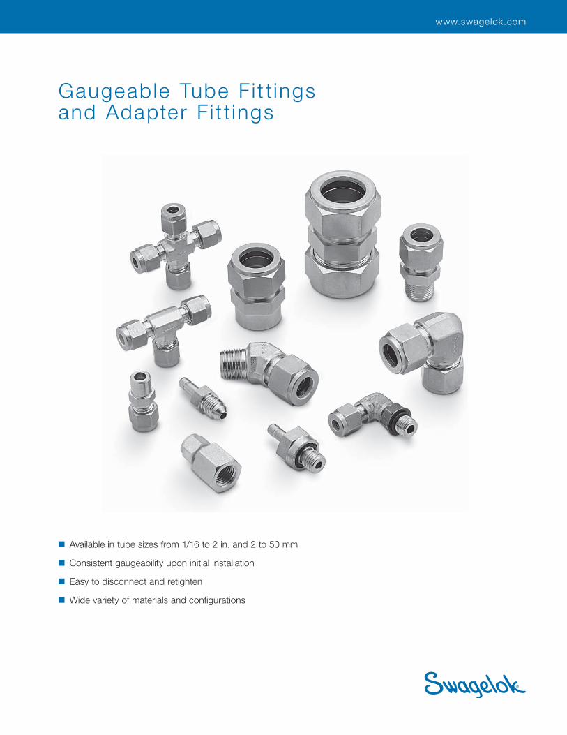
Gaugeable Tube Fi t t ingsand Adapter F i t t ings
■ Available in tube sizes from 1/16 to 2 in. and 2 to 50 mm
■ Consistent gaugeability upon initial installation
■ Easy to disconnect and retighten
■ Wide variety of materials and confi gurations
Gaugeable Tube Fittings and Adapter Fittings 2
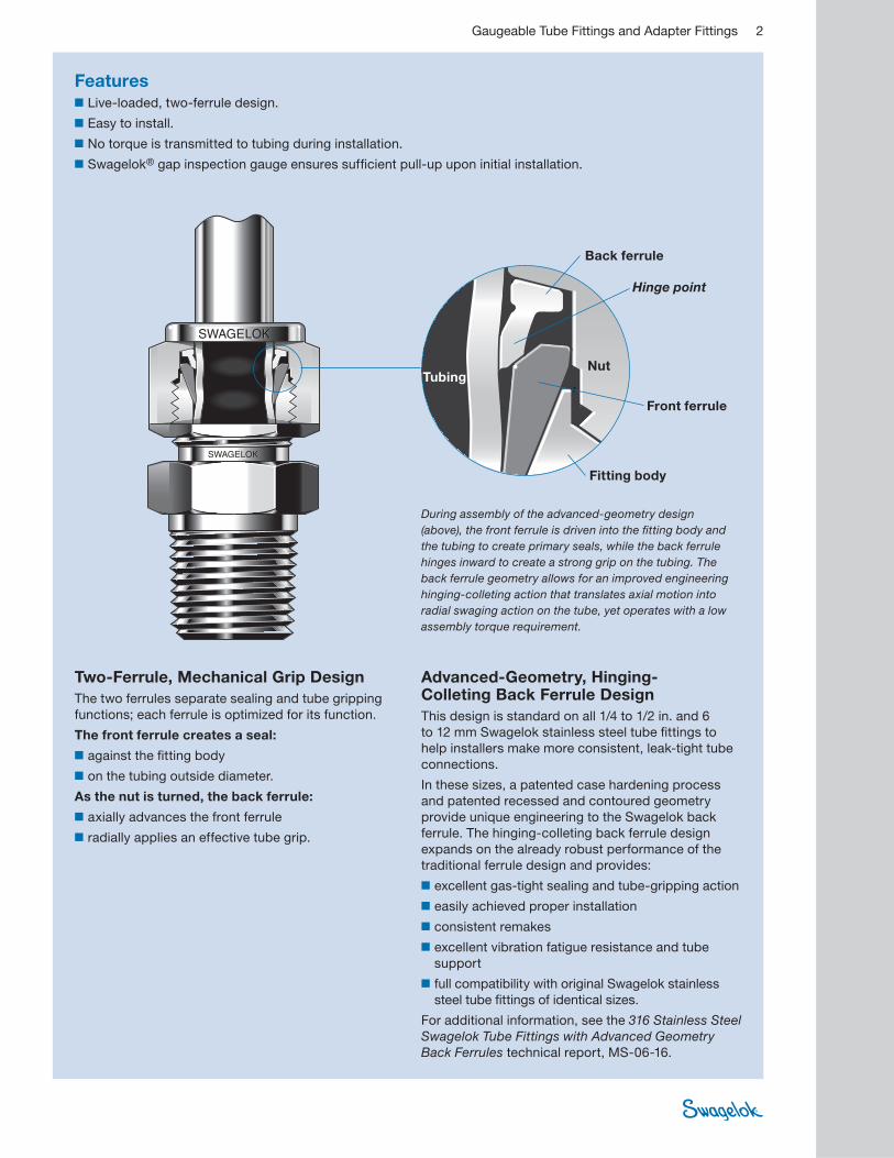
Features■ Live-loaded, two-ferrule design.
■ Easy to install.
■ No torque is transmitted to tubing during installation.
■ Swagelok® gap inspection gauge ensures suffi cient pull-up upon initial installation.
Two-Ferrule, Mechanical Grip Design
The two ferrules separate sealing and tube gripping
functions; each ferrule is optimized for its function.
The front ferrule creates a seal:
■ against the fi tting body
■ on the tubing outside diameter.
As the nut is turned, the back ferrule:
■ axially advances the front ferrule
■ radially applies an effective tube grip.
Advanced-Geometry, Hinging-Colleting Back Ferrule Design
This design is standard on all 1/4 to 1/2 in. and 6
to 12 mm Swagelok stainless steel tube fi ttings to
help installers make more consistent, leak-tight tube
connections.
In these sizes, a patented case hardening process
and patented recessed and contoured geometry
provide unique engineering to the Swagelok back
ferrule. The hinging-colleting back ferrule design
expands on the already robust performance of the
traditional ferrule design and provides:
■ excellent gas-tight sealing and tube-gripping action
■ easily achieved proper installation
■ consistent remakes
■ excellent vibration fatigue resistance and tube
support
■ full compatibility with original Swagelok stainless
steel tube fi ttings of identical sizes.
For additional information, see the 316 Stainless Steel
Swagelok Tube Fittings with Advanced Geometry
Back Ferrules technical report, MS-06-16.
Front ferrule
Back ferrule
TubingNut
Fitting body
During assembly of the advanced-geometry design
(above), the front ferrule is driven into the fi tting body and
the tubing to create primary seals, while the back ferrule
hinges inward to create a strong grip on the tubing. The
back ferrule geometry allows for an improved engineering
hinging-colleting action that translates axial motion into
radial swaging action on the tube, yet operates with a low
assembly torque requirement.
Hinge point

3 Gaugeable Tube Fittings and Adapter Fittings
Straight Fittings
Unions
Union, 10
Reducing Union,
11
Bulkhead Union
and Bulkhead
Reducing
Union, 12
Male Connectors
NPT, 13
ISO/BSP Tapered
Thread (RT), 14
ISO/BSP Parallel
Thread (RS), 15
ISO/BSP Parallel
Thread (RP), 16
Bulkhead
NPT, 17
SAE/MS Straight
Thread (ST)
and Long SAE/
MS Straight
Thread (ST), 17
O-Seal (SAE/MS
Straight Thread
and NPT), 18
AN and
AN Bulkhead
Fitting, 19
10-32 Thread,
M5 � 0.8
Thread, and
Metric Thread
(RS), 20
Features, 2
The Swagelok Tube Fitting Advantage, 6
Materials, 8
Alternative Fuels-Type Approval, 8
Thread Specifi cations, 8
O-Rings, 8
Cleaning and Packaging, 8
Metric Swagelok Tube Fittings, 8
Pressure Ratings, 9
Ordering Numbers and Dimensions, 10
Weld Connectors
Tube Socket, 20
Male Pipe, 21
Female Connectors
NPT, 22
ISO/BSP Tapered
Thread (RT),
ISO/BSP Parallel
Thread (RJ and
RP), 23
ISO/BSP Parallel
Thread (RG,
Gauge), 24
Bulkhead
NPT, 24
Reducers
Reducer, 25
Long Reducer,
26
Bulkhead
Reducer, 26
Port Connectors
Port Connector
and Reducing
Port Connector,
27
Contents
Additional Products
■ For SAF 2507 super duplex
tube fi ttings, see the
Swagelok Gaugeable SAF
2507™ Super Duplex Tube
Fittings catalog, MS-01-174.
■ For PFA tube fi ttings, see the
Swagelok PFA Tube Fittings
and PFA Tubing catalog,
MS-01-05.
■ For heavy-wall tube fi ttings,
see the Swagelok High-
Pressure Fittings catalog,
MS-01-34.

4 Gaugeable Tube Fittings and Adapter Fittings
45° Elbows
Male
NPT, 34
Positionable,
SAE/MS Straight
Thread (ST), 34
Tees
Unions
Union and Reducing
Union, 35
Male
Branch, NPT
(TTM), 37
Run, NPT (TMT), 37
Positionable Branch,
SAE/MS Straight
Thread (TTS) and
Positionable Branch,
ISO/BSP Parallel
Thread (TTR), 38
Positionable Run,
SAE/MS Straight
Thread (TST), 38
Positionable Run,
ISO/BSP Parallel
Thread (TRT), 39
Caps and Plugs
Cap, 28
Plug, 28
Vent Protectors
Mud Dauber, 28
90° Elbows
Unions
Union, 29
Male
NPT, 30
ISO/BSP Tapered
Thread (RT), 31
Reducing, 31
Positionable, ISO/
BSP Parallel Thread
(PR) and Positionable,
SAE/MS Straight
Thread (ST), 32
Weld
Tube Socket, 33
Male Pipe, 33
Female
NPT, 33
Female
Run, NPT (TFT), 39
Branch, NPT
(TTF), 40
Cross
Union, 40
Sanitary Flange Fittings
Kwik-Clamp Flange
to Swagelok Tube
Fitting, 41
Tube Adapters
Tube Adapter Information, 42
Male
NPT and ISO/BSP
Tapered Thread
(RT), 43
ISO/BSP Parallel
Thread (RS and RP),
44
SAE/MS Straight
Thread (ST) and
O-Seal (SAE/MS
Straight Thread), 45
AN Thread, 45
Pipe Weld, 46
Contents
Gaugeable Tube Fittings and Adapter Fittings 5
Female
NPT and ISO/BSP
Tapered Thread
(RT), 46
ISO/BSP Parallel
Thread (RP and
RJ), and ISO/BSP
Parallel Thread (RG,
Gauge), 47
AN Thread, 47
Additional Ordering
Information, 48
Replacement Parts
Nuts
Female, 50
Knurled Female, 50
Male, 50
Ferrules
Front, 51
Back, 51
Nut-Ferrule Set and
Package and
Ferrule Set and
Ferrule-Pak™
Package, 52
ISO/BSP Parallel Gaskets
Steel (RS Fitting),
Copper (RP Fitting),
Copper (RG, Gauge
Fitting), and PTFE
(RJ Fitting), 53
O-Rings
Buna N (O-Seal
Straight Threads
and O-Seal Pipe
Threads) and
Fluorocarbon FKM
(ISO/BSP Parallel
Threads and
SAE/MS Straight
Threads), 8
Tools and Accessories
For tube benders, wrenches, cutters,
liquid leak detectors, and more, see
the Swagelok Tools and Accessories
catalog, MS-01-169.
Gap Inspection
Gauge and Depth
Marking Tool, 55
Bulkhead Retainer,
56
Insert for Soft
Plastic Tubing, 56
Preswaging Tool, 57
Hydraulic Swaging Units, 57
Gaugeability, 58
Installation Instructions, 58
The Swagelok LimitedLifetime Warranty, 62
Bored-Through Fittings
For thermocouples, dip tubes, and
heat exchanger tees, 16
Chromatograph Fittings
See the Swagelok
Gaugeable
Chromatograph and
Column End Fittings
catalog, MS-02-173.
Dielectric Fittings
See the Swagelok
Dielectric
Fittings catalog,
MS-02-36-SCS.
Flanges
For ANSI, DIN, and
JIS fl anges, see the
Swagelok Flange
Adapters catalog,
MS-02-200.
VCO® and VCR®
Face Seal Fittings
See the Swagelok
VCR Metal Gasket
Face Seal Fittings
and VCO O-Rings
Face Seal Fittings
catalogs, MS-01-24
and MS-01-28.
Contents

6 Gaugeable Tube Fittings and Adapter Fittings
“Over 10 000 fittings and not a single leak.”
That is the message one customer
wanted to share, crediting Swagelok
components and tube fi ttings
along with Swagelok distributor
support, as having played a major
role in completing—and obtaining
independent, third-party certifi cation
for—two 12 000 ton oil rigs.
And that is part of the ongoing story
behind the continuous improvement
efforts that Swagelok has initiated and
sustained since the development and
patent of the original two-ferrule tube
fi tting more than 50 years ago.
Today, as everyone is being called on
to “do more with less” and to recognize
value, Swagelok continues to improve
the leak-tight design of the tube
fi tting for use in thousands of diverse
applications—including research,
analytical and process instrumentation,
bioprocessing, oil and gas, power,
petrochemical, and semiconductor
industries—and addressing such
critical issues as:
■ leakage
■ vibration (tube grip)
■ thermal shock
■ compliance with industry standards
■ installation
■ corrosion
■ intermix/interchange.
Leakage
Excellent gas-tight sealing and
consistent reassembly help ensure
accurate measurements of process
parameters—air, steam, fuel, and
water—to keep your plant operating
effi ciently. Moreover, Swagelok tube
fi ttings minimize fugitive emissions,
as well as process fl uid leakage and
operation costs.
From 1999 through 2004, more than
250 000 fi ttings in gas service at more
than 400 different process installations
were leak tested with Swagelok Snoop®
liquid leak detector. Contact your
authorized Swagelok sales and service
representative for more information
about Swagelok Energy Emissions
Surveys or to schedule a survey.
Vibration (Tube Grip)
The patented case-hardening process
and back-ferrule geometry provide
excellent vibration fatigue resistance
and tube support—even in harsh
or stressful environments, such as
fuel processing or rotary equipment
applications.
Swagelok has conducted rotary fl ex
tests, which show that the Swagelok
tube fi tting with advanced geometry
hinging-colleting back ferrule isolates
and protects the stress riser that
is generated along the tube during
the gripping part of assembly. The
colleting portion of the back ferrule
allows more material to contact the
tube, for additional support. This
colleting action enhances gripping
performance and provides both direct
and axial support to the gripping
function. This design minimizes the
effects of bending defl ection at the
point of grip on the tubing.
Contact your authorized Swagelok
representative for more information
about vibration test reports.
The Swagelok Tube Fitting Advantage

Gaugeable Tube Fittings and Adapter Fittings 7
Corrosion
Swagelok tube fi ttings are available
in a variety of materials, including
controlled-chemistry 316 stainless
steel and many other alloys for
enhanced corrosion resistance in a
variety of applications, including sour
gas and subsea systems.
Swagelok has conducted tests in
accordance with ASTM B117-95 to
evaluate the corrosion resistance of
Swagelok tube fi ttings.
Contact your authorized Swagelok
representative for more information
about corrosion resistance test reports.
Intermix/Interchange
This practice can be dangerous.
Leak-tight seals that will withstand
high pressure, vibration, vacuum, and
temperature changes depend on close
tolerances and consistent, exacting
quality control in conjunction with
good design principles.
Components of other manufacturers
may look like Swagelok tube fi tting
components—but they cannot be
manufactured in accordance with
Swagelok engineering standards, nor
do they benefi t from innovations in
design and manufacture defi ned by 36
active Swagelok tube fi tting patents
issued since 1989.
Thermal Shock
The elastic, live-loaded two-ferrule
design compensates for changes in
temperature during system start-up
and shutdown and helps eliminate
leakage related to rapid thermal
expansion or contraction.
Swagelok has conducted tests
that demonstrated the capability of
Swagelok tube fi ttings to withstand
thermal shock and high temperature.
Contact your authorized Swagelok
representative for more information
about thermal shock test reports.
Compliance with Industry Standards
Swagelok Company works with
standards organizations around the
world to provide you with products that
address your needs.
See Materials, page 8; Thread
Specifi cations, page 8; and
Pressure Ratings, page 9, for more
information about the specifi cations
to which Swagelok tube fi ttings are
manufactured.
Contact your authorized Swagelok
representative for more information
about Swagelok tube fi tting
certifi cations.
Installation
The Swagelok tube fi tting installation
advantages:
■ Easy to install
■ No torque is transmitted to tubing
during installation
■ Swagelok gap inspection gauge
assures suffi cient pull-up upon initial
installation.
Swagelok tube fi tting components
provide exceptional dimensional,
metallurgical, and mechanical
uniformity that allow predictable,
repeatable installation.
Swagelok authorized sales and service
centers offer installation training
seminars that provide additional
information on:
■ The requirements for making safe,
leak-tight connections
■ A variety of tools and accessories
designed for use with Swagelok tube
fi ttings.
8 Gaugeable Tube Fittings and Adapter Fittings
O-RingsO-seal fi ttings include a 70 durometer Buna N O-ring.
Other straight-thread fi ttings with O-rings include a 90
durometer fl uorocarbon FKM O-ring. Other O-ring materials
are available upon request. O-rings are coated with a thin
fi lm of silicone-based lubricant. Removal of factory-applied
lubricants may alter performance.
Materials
Pipe Thread Sealants
A thread sealant should always be used when assembling
tapered threads. SWAK® anaerobic pipe thread sealant and
Swagelok PTFE tape are available. For more information, see
the Swagelok Tools and Accessories catalog, MS-01-169.
Cleaning and PackagingFitting components are cleaned to remove machine oil, grease,
and loose particles. For more information, see Swagelok
Standard Cleaning and Packaging (SC-10), MS-06-62.
Fittings are available individually bagged; add CP to the
ordering number.
Example: SS-200-6CP
On request, fi ttings can be cleaned and packaged in
accordance with Swagelok Special Cleaning and Packaging
(SC-11), MS-06-63, with front ferrules silver plated and
Krytox® 240 AC applied to the internal surface of the nut.
To order, add -BQ to the ordering number.
Example: SS-400-1-4-BQ
Oxygen Service Hazards
For more information about hazards and risks of oxygen-
enriched systems, see the Swagelok Oxygen System Safety
technical report, MS-06-13.
Materials Standards
➀ Straight fi ttings and tube adapters.
➁ Elbows, crosses, and tees.
➂ All straight fittings and tube adapters and 1/4 and 3/8 in.; 6 and 10 mm elbows, crosses, and tees.
➃ Elbows, crosses, and tees larger than 3/8 in. and 10 mm.
➄ See the Swagelok PFA Tube Fittings and PFA Tubing catalog, MS-01-05.
➅ See the Swagelok Gaugeable SAF 2507 Super Duplex Tube Fittings catalog, MS-01-174.
Material Bar Stock➀ Forgings➁
316 stainless steel
ASTM A276, ASME SA479, EN 1.4401
ASTM A182, ASME SA182, EN 1.4401
Alloy 20 ASTM B473 ASTM B462
Alloy 400/R-405
ASTM B164, ASME SB164
ASTM B564, ASME SB564
Alloy 600 ASTM B166, ASME SB166 ASTM B564, ASME SB564
Alloy 625 ASTM B446➂ ASTM B564, ASME SB564➃
Alloy 825 ASTM B425 ASTM B564, ASME SB564
Alloy C-276 ASTM B574 ASTM B564
Aluminum ASTM B211 ASTM B247
Brass ASTM B16, ASTM B453 ASTM B283
Carbon steel ASTM A108 —
Nylon ASTM D4066 —
PFA➄ — ASTM D3307 Type I
PTFE ASTM D1710 ASTM D3294
SAF 2507➅ ASTM A479 ASTM A182
Titanium (grade 4)
ASTM B348 ASTM B381
Thread Specifi cations
Thread Type (End Connection) Reference Specification
NPT ASME B1.20.1, SAE AS71051
ISO/BSP (parallel) (Based on DIN 3852)
(Swagelok PR, RP, and RS fittings) ISO 228, JIS B0202
ISO/BSP (tapered) (Based on DIN 3852) (Swagelok RT fittings)
ISO 7, BS EN 10226-1, JIS B0203
ISO/BSP (gauge)(Based on EN 837-1 and 837-3) (Swagelok RG and RJ fittings)
ISO 228, JIS B0202
Unified (SAE) (Swagelok ST fittings)
ASME B1.1
Additional Processing
Fitting bodies are processed for improved performance, as
listed below. No additional processing is required for alloy 625,
alloy 825, brass, nylon, 316 stainless steel, and PTFE materials.
■ Over 1 in. and over 25 mm stainless steel fi ttings use
stainless steel ferrules with PFA coating. Applications
above 450°F (232°C) require silver-plated front ferrules and
uncoated back ferrules. To order fi ttings with silver-plated
front ferrules and uncoated back ferrules, add -BM to the
fi tting ordering number.
Example: SS-2400-6-BM
■ All carbon steel Swagelok tube fi ttings are supplied with
316 stainless steel back ferrules.
Fitting Body Material Process
Aluminum Anodized, hydrocarbon film
Alloy 400/R-405, alloy 20, alloy C-276, alloy 600
Hydrocarbon film
Carbon steel (except weld bodies) Zinc plating
Carbon steel (weld bodies) Hydrocarbon film chemical
conversion coating
Titanium Anodized
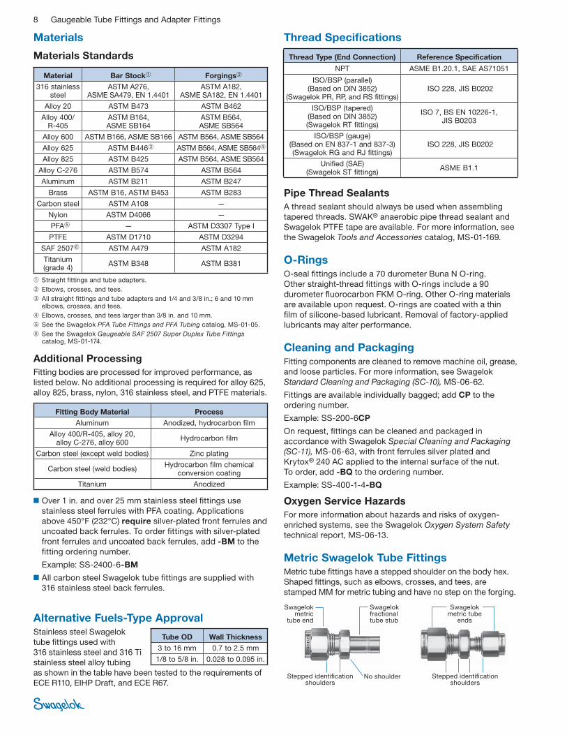
Metric Swagelok Tube FittingsMetric tube fi ttings have a stepped shoulder on the body hex.
Shaped fi ttings, such as elbows, crosses, and tees, are
stamped MM for metric tubing and have no step on the forging.
Swagelokmetric
tube end
Swagelokfractionaltube stub
No shoulderStepped identifi cation shoulders
Stepped identifi cation shoulders
Swagelok metric tube
ends Alternative Fuels-Type ApprovalStainless steel Swagelok
tube fi ttings used with
316 stainless steel and 316 Ti
stainless steel alloy tubing
as shown in the table have been tested to the requirements of
ECE R110, EIHP Draft, and ECE R67.
Tube OD Wall Thickness
3 to 16 mm 0.7 to 2.5 mm
1/8 to 5/8 in. 0.028 to 0.095 in.

Gaugeable Tube Fittings and Adapter Fittings 9
Pressure Ratings
O-Seal Pressure Ratings
Stainless steel and carbon steel O-seal fi ttings up to 1 in. and
25 mm are rated to 3000 psig (206 bar).
Pipe End (NPT and ISO 7) Pressure Ratings Basis
Pressure ratings for fi ttings with both tube fi tting and pipe
thread ends are determined by the end connection with the
lower pressure rating. The table lists pressure ratings for male
and female tapered pipe thread ends. For female and male
pipe threads to have the same pressure rating in the same
nominal pipe size, the female thread would require a heavier
wall, resulting in a fi tting too large and bulky to be practical.
■ To determine pressure ratings in accordance with
ASME B31.1, Power Piping:
■ stainless steel material—multiply by 0.94
■ carbon steel material—multiply by 0.85.
Brass material ratings remain the same.
■ To determine MPa, multiply bar by 0.10.
Pressure Ratings
Ratings are based on ASME Code for Pressure Piping B31.3,
Process Piping, at ambient temperature.
Allowable Stress
Stress values are based on ASME Code for Pressure Piping
B31.3, Process Piping, at ambient temperature.
SAE/MS Fittings Pressure Ratings Basis
Pressure ratings are based on SAE J1926/3 at ambient
temperature.
Some fi ttings with AN, O-seal, and SAE/MS ends may have
lower ratings. For more information, contact your authorized
Swagelok representative.
Swagelok Tube Fitting Pressure Ratings
Swagelok tube fi tting ends are rated to the working pressure
of tubing as listed in Swagelok Tubing Data, MS-01-107.
Careful selection of high-quality tubing is important when
installing safe, leak-tight systems.
Material
Allowable Stress
psi bar
316 SS 20 000 1378
Brass 10 000 689
Steel 20 000 1378
NPT/ISO Pipe Size in.
316 SS and Carbon Steel Brass
Male Female Male Female
psig bar psig bar psig bar psig bar
1/16 11 000 760 6700 460 5500 380 3300 230
1/8 10 000 690 6500 440 5000 340 3200 220
1/4 8 000 550 6600 450 4000 270 3300 220
3/8 7 800 540 5300 360 3900 270 2600 180
1/2 7 700 530 4900 330 3800 260 2400 160
3/4 7 300 500 4600 320 3600 250 2300 160
1 5 300 370 4400 300 2600 180 2200 150
1 1/4 6 000 410 5000 350 3000 200 2500 170
1 1/2 5 000 340 4600 310 2500 170 2300 150
2 3 900 270 3900 270 1900 130 1900 130
SAE/MS Thread Size Designator
316 SS and Carbon Steel
Nonpositionable Positionable
psig bar psig bar
5/16-24 2ST
4568 315
4568 315 7/16-20 4ST
1/2-20 5ST
9/16-18 6ST3626 250
3/4-16 8ST
7/8-14 10ST3626 250 2900 200
1 1/16-12 12ST
1 3/16-12 14ST2900 200 2320 160
1 5/16-12 16ST
1 5/8-12 20ST2320 160 1813 125
1 7/8-12 24ST
2 1/2-12 32ST 1813 125 1450 100
Positionable, ISO/BSP Parallel Thread (PR) Pressure Ratings
Pressure ratings are at ambient temperature.
ISO/BSP Male Pipe
Size in.
316 SS and Carbon Steel
psig bar
1/8
4568 3151/4
3/8
1/2
2320 1603/4
1
10 Gaugeable Tube Fittings and Adapter Fittings
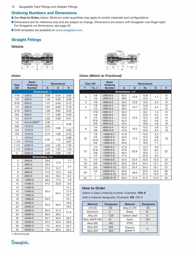
Union
D DA
E
Ordering Numbers and Dimensions ■ See How to Order, below. Minimum order quantities may apply to certain materials and confi gurations.
■ Dimensions are for reference only and are subject to change. Dimensions are shown with Swagelok nuts fi nger-tight.
For Swagelok nut dimensions, see page 50.
■ CAD templates are available on www.swagelok.com.
Straight Fittings
Unions
Union (Metric to Fractional)
D DxA
E
F fl at
Tx
T
➀ Bored through.
Tube OD
Basic Ordering Number
Dimensions
A D E
Dimensions, in.
1/16 -100-6 0.99 0.34 0.05
1/8 -200-6 1.40 0.50 0.09
3/16 -300-6 1.47 0.54 0.12
1/4 -400-6 1.61 0.60 0.19
5/16 -500-6 1.69 0.64 0.25
3/8 -600-6 1.77 0.66 0.28
1/2 -810-6 2.02 0.90 0.41
1/2 -810-6-0030➀ 4.30 —0.50
5/8 -1010-6 2.05 0.96
3/4 -1210-6 2.11 0.62
7/8 -1410-6 2.17 1.02 0.72
1 -1610-6 2.55 1.23
0.88
1 1/8 -1810-6 0.97
1 1/4 -2000-6 3.63 1.62 1.09
1 1/2 -2400-6 4.25 1.97 1.34
2 -3200-6 5.88 2.66 1.81
Dimensions, mm
2 -2M0-6 35.6 12.9
1.7
3 -3M0-6 35.3 2.4
4 -4M0-6 37.3 13.7
6 -6M0-6 41.0 15.3 4.8
8 -8M0-6 43.2 16.2 6.4
10 -10M0-6 46.2 17.2 7.9
12 -12M0-6 51.2 22.8 9.5
14 -14M0-6
52.0 24.4
11.1
15 -15M0-6 11.9
16 -16M0-6 12.7
18 -18M0-6 53.5 15.1
20 -20M0-6 55.0 26.0
15.9
22 -22M0-6 18.3
25 -25M0-6 65.0 31.3 21.8
28 -28M0-6 85.0 36.6
30 -30M0-6 92.7 39.6 26.2
32 -32M0-6 97.3 42.0 28.6
38 -38M0-6 114 49.4 33.7
50 -50M0-6 146 65.0 45.2
Tube ODBasic
Ordering Number
Dimensions
T Tx, in. A D Dx E F
Dimensions, mm
2 1/8 1/4
-2M0-6-2 -2M0-6-4
35.2 38.6
12.9 12.8 15.3
1.7 12 14
3 1/8 -3M0-6-2 35.2 12.9 12.8 2.4 12
4 1/8 1/4
-4M0-6-2 -4M0-6-4
36.5 39.4
13.7 12.8 15.3
2.4 12 14
6
1/16 1/8 1/4 5/16 3/8
-6M0-6-1 -6M0-6-2 -6M0-6-4 -6M0-6-5 -6M0-6-6
34.3 38.5 41.0 42.3 43.2
15.3
8.6 12.8 15.3 16.2 16.8
1.3 2.4 4.8 4.8 4.8
14 14 14 14 16
8 1/4 3/8
-8M0-6-4 -8M0-6-6
42.3 44.3
16.2 15.3 16.9
4.8 6.4
15 16
10
1/8 1/4 5/16 3/8
-10M0-6-2 -10M0-6-4 -10M0-6-5 -10M0-6-6
41.8 44.5 45.1 45.9
17.2
12.8 15.3 16.2 16.9
2.4 4.8 6.4 7.1
18
12
1/4 5/16 3/8 1/2
-12M0-6-4 -12M0-6-5 -12M0-6-6 -12M0-6-8
47.0 47.8 48.4 51.2
22.8
15.3 16.2 16.9 22.8
4.8 6.4 7.1 9.5
22
15 1/2 -15M0-6-8 52.0 24.4 22.8 10.3 24
16 5/8 -16M0-6-10 52.0 24.4 24.4 12.7 24
18 3/4 -18M0-6-12 53.5 24.4 24.4 15.1 27
20 1/2 1
-20M0-6-8 -20M0-6-16
55.0 62.8
26.0 22.8 31.3
10.3 15.9
30 35
25 1 -25M0-6-16 65.0 31.3 31.3 21.8 35
How to Order
Select a basic ordering number. Example -100-6
Add a material designator. Example: SS-100-6
Material Designator Material Designator
316 SS SS Alloy C-276 HC
Aluminum A Brass B
Alloy 20 C20 Carbon steel S
Alloy 400/R-405 M Nylon NY
Alloy 600 INC PTFE T
Alloy 625 625 Titanium (grade 4)
TIAlloy 825 825
Gaugeable Tube Fittings and Adapter Fittings 11
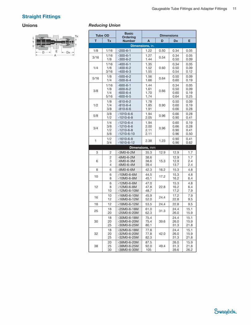
Unions
Tx
T
D DxA
E
Reducing Union
Tube OD Basic
OrderingNumber
Dimensions
T Tx A D Dx E
Dimensions, in.
1/8 1/16 -200-6-1 1.22 0.50 0.34 0.05
3/16 1/16 1/8
-300-6-1 -300-6-2
1.27 1.44
0.54 0.34 0.50
0.05 0.09
1/4 1/16 1/8 3/16
-400-6-1 -400-6-2 -400-6-3
1.35 1.52 1.55
0.60 0.34 0.50 0.54
0.05 0.09 0.12
5/16 1/8 1/4
-500-6-2 -500-6-4
1.56 1.66
0.64 0.50 0.60
0.09 0.19
3/8
1/16 1/8 1/4 5/16
-600-6-1 -600-6-2 -600-6-4 -600-6-5
1.44 1.61 1.70 1.74
0.66
0.34 0.50 0.60 0.64
0.05 0.09 0.19 0.25
1/2 1/8 1/4 3/8
-810-6-2 -810-6-4 -810-6-6
1.78 1.85 1.91
0.90 0.50 0.60 0.66
0.09 0.19 0.28
5/8 3/8 1/2
-1010-6-6 -1010-6-8
1.94 2.05
0.96 0.66 0.90
0.28 0.41
3/4
1/4 3/8 1/2 5/8
-1210-6-4 -1210-6-6 -1210-6-8 -1210-6-10
1.94 2.00 2.11 2.11
0.96
0.60 0.66 0.90 0.96
0.19 0.28 0.41 0.50
1 1/2 3/4
-1610-6-8 -1610-6-12
2.38 1.23 0.90 0.96
0.41 0.62
Dimensions, mm
3 2 -3M0-6-2M 35.3 12.9 12.9 1.7
6 2 3 4
-6M0-6-2M -6M0-6-3M -6M0-6-4M
38.6 38.6 39.4
15.3 12.9 12.9 13.7
1.7 2.4 2.4
8 6 -8M0-6-6M 42.3 16.2 15.3 4.8
10 6 8
-10M0-6-6M -10M0-6-8M
44.5 45.1
17.2 15.3 16.2
4.8 6.4
12 6 8
10
-12M0-6-6M -12M0-6-8M -12M0-6-10M
47.0 47.8 48.7
22.8 15.3 16.2 17.2
4.8 6.4 7.9
16 10 12
-16M0-6-10M -16M0-6-12M
45.9 52.0
24.4 17.2 22.8
7.9 9.5
18 12 -18M0-6-12M 53.5 24.4 22.8 9.5
25 18 20
-25M0-6-18M -25M0-6-20M
61.0 62.3
31.3 24.4 26.0
15.1 15.9
30 18 20 25
-30M0-6-18M -30M0-6-20M -30M0-6-25M
75.4 75.4 80.1
39.6 24.4 26.0 31.3
15.1 15.9 21.8
32 18 20 25
-32M0-6-18M -32M0-6-20M -32M0-6-25M
77.8 77.8 82.3
42.0 24.4 26.0 31.3
15.1 15.9 21.8
38 20 25 30
-38M0-6-20M -38M0-6-25M -38M0-6-30M
87.5 92.0 105
49.4 26.0 31.3 39.6
15.9 21.8 26.2
Straight Fittings

12 Gaugeable Tube Fittings and Adapter Fittings
Bulkhead Union
➀ Minimum panel thickness is 0.06 in.
D DA
E
F fl atF fl at F fl at
Unions
Tube OD
Basic OrderingNumber
Dimensions
A D E F
Panel Hole Size
Max Panel
Thickness
Dimensions, in.
1/16 -100-61 1.24 0.34 0.05 5/16 13/64 0.12➀
1/8 -200-61 2.02 0.50 0.09 1/2 21/64 0.50
3/16 -300-61 2.11 0.54 0.12 9/16 25/64
1/4 -400-61 2.27 0.60 0.19 5/8 29/64 0.40
5/16 -500-61 2.39 0.64 0.25 11/16 33/64 0.44
3/8 -600-61 2.45 0.66 0.28 3/4 37/64
1/2 -810-61 2.80 0.90 0.41 15/16 49/64 0.50
5/8 -1010-61 2.86 0.96 0.50 1 1/16 57/64
3/4 -1210-61 3.11 0.96 0.62 1 3/16 1 1/64 0.66
1 -1610-61 3.77 1.23 0.88 1 5/8 1 21/64
0.75 1 1/4 -2000-61 4.85 1.62 1.09 1 7/8 1 41/64
1 1/2 -2400-61 5.48 1.97 1.34 2 1/4 1 61/64
2 -3200-61 7.10 2.66 1.81 2 3/4 2 41/64
Dimensions, mm
3 -3M0-61 51.3 12.9 2.4 14
8.3 12.7
4 -4M0-61 53.6 13.7 2.4 9.9
6 -6M0-61 57.7 15.3 4.8 16 11.5 10.2
8 -8M0-61 61.0 16.2 6.4 18 13.1 11.2
10 -10M0-61 63.7 17.2 7.9 22 16.3
12 -12M0-61 71.0 22.8 9.5 24 19.5
12.7 14 -14M0-61 72.5 24.4 11.1
27
22.5
15 -15M0-61 72.5 24.4 11.9 22.8
16 -16M0-61 72.5 24.4 12.7
18 -18M0-61 78.9 24.4 15.1 30 26.0 16.8
20 -20M0-61 84.5 26.0 15.9 35 29.0
19.0
25 -25M0-61 96.0 31.3 21.8 41 34.0
30 -30M0-61 124 39.6 26.2 50
40.5
32 -32M0-61 128 42.0 28.6 42.5
38 -38M0-61 145 49.4 33.7 60 50.5
Bulkhead Reducing Union (Metric to Fractional)
Tube OD
Basic OrderingNumber
Dimensions
T Tx, in. A D Dx E F
Panel Hole Size
Max Panel
Thickness
Dimensions, mm
6 1/8 -6M0-61-2 55.1 15.3 12.7 2.4 16 11.5 10.2
Straight Fittings
Bulkhead Reducing Union
D DxA
E
F fl atF fl at F fl at
Tx
Tube OD
Basic OrderingNumber
Dimensions
T Tx A D Dx E F
Panel Hole Size
Max Panel
Thickness
Dimensions, in.
1/8 1/16 -200-61-1 1.85 0.50 0.34 0.05 1/2 21/64 0.50
1/4 1/8 -400-61-2 2.17 0.60 0.50 0.09 5/8 29/64 0.40
3/8 1/4 -600-61-4 2.39 0.66 0.60 0.19
3/4 37/64 0.44
1/2 1/4 -810-61-4 2.63 0.90 15/16 49/64 0.50
T
Gaugeable Tube Fittings and Adapter Fittings 13
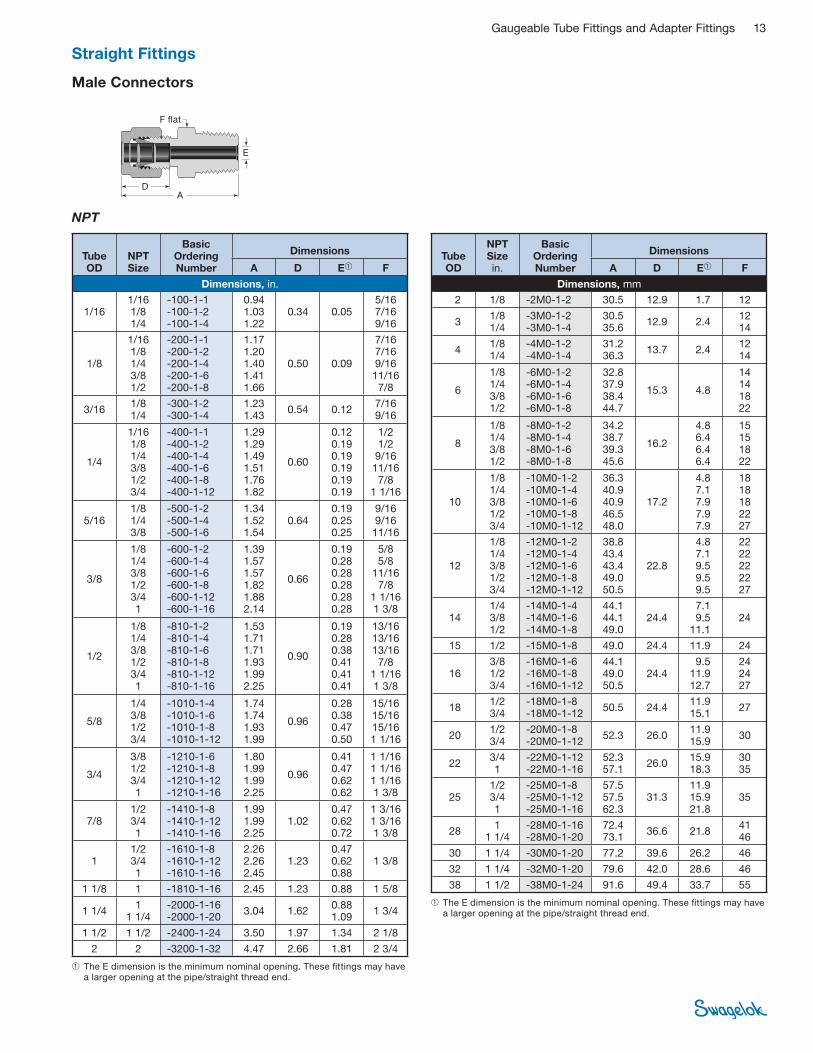
Male Connectors
NPT
➀ The E dimension is the minimum nominal opening. These fi ttings may have a larger opening at the pipe/straight thread end.
DA
E
F fl at
➀ The E dimension is the minimum nominal opening. These fi ttings may have a larger opening at the pipe/straight thread end.
Tube OD
NPT Size
Basic Ordering Number
Dimensions
A D E➀ F
Dimensions, in.
1/16 1/16 1/8 1/4
-100-1-1 -100-1-2 -100-1-4
0.94 1.03 1.22
0.34 0.05 5/16 7/16 9/16
1/8
1/16 1/8 1/4 3/8 1/2
-200-1-1 -200-1-2 -200-1-4 -200-1-6 -200-1-8
1.17 1.20 1.40 1.41 1.66
0.50 0.09
7/16 7/16 9/16 11/16 7/8
3/16 1/8 1/4
-300-1-2 -300-1-4
1.23 1.43
0.54 0.12 7/16 9/16
1/4
1/16 1/8 1/4 3/8 1/2 3/4
-400-1-1 -400-1-2 -400-1-4 -400-1-6 -400-1-8 -400-1-12
1.29 1.29 1.49 1.51 1.76 1.82
0.60
0.12 0.19 0.19 0.19 0.19 0.19
1/2 1/2 9/16 11/16 7/8
1 1/16
5/16 1/8 1/4 3/8
-500-1-2 -500-1-4 -500-1-6
1.34 1.52 1.54
0.64 0.19 0.25 0.25
9/16 9/16 11/16
3/8
1/8 1/4 3/8 1/2 3/4 1
-600-1-2 -600-1-4 -600-1-6 -600-1-8 -600-1-12 -600-1-16
1.39 1.57 1.57 1.82 1.88 2.14
0.66
0.19 0.28 0.28 0.28 0.28 0.28
5/8 5/8
11/16 7/8
1 1/16 1 3/8
1/2
1/8 1/4 3/8 1/2 3/4 1
-810-1-2 -810-1-4 -810-1-6 -810-1-8 -810-1-12 -810-1-16
1.53 1.71 1.71 1.93 1.99 2.25
0.90
0.19 0.28 0.38 0.41 0.41 0.41
13/16 13/16 13/16 7/8
1 1/16 1 3/8
5/8
1/4 3/8 1/2 3/4
-1010-1-4 -1010-1-6 -1010-1-8 -1010-1-12
1.74 1.74 1.93 1.99
0.96
0.28 0.38 0.47 0.50
15/16 15/16 15/16 1 1/16
3/4
3/8 1/2 3/4 1
-1210-1-6 -1210-1-8 -1210-1-12 -1210-1-16
1.80 1.99 1.99 2.25
0.96
0.41 0.47 0.62 0.62
1 1/16 1 1/16 1 1/16 1 3/8
7/8 1/2 3/4 1
-1410-1-8 -1410-1-12 -1410-1-16
1.99 1.99 2.25
1.02 0.47 0.62 0.72
1 3/16 1 3/16 1 3/8
1 1/2 3/4 1
-1610-1-8 -1610-1-12 -1610-1-16
2.26 2.26 2.45
1.23 0.47 0.62 0.88
1 3/8
1 1/8 1 -1810-1-16 2.45 1.23 0.88 1 5/8
1 1/4 1
1 1/4 -2000-1-16 -2000-1-20
3.04 1.62 0.88 1.09
1 3/4
1 1/2 1 1/2 -2400-1-24 3.50 1.97 1.34 2 1/8
2 2 -3200-1-32 4.47 2.66 1.81 2 3/4
Tube OD
NPT Size in.
Basic Ordering Number
Dimensions
A D E➀ F
Dimensions, mm
2 1/8 -2M0-1-2 30.5 12.9 1.7 12
3 1/8 1/4
-3M0-1-2 -3M0-1-4
30.5 35.6
12.9 2.4 12 14
4 1/8 1/4
-4M0-1-2 -4M0-1-4
31.2 36.3
13.7 2.4 12 14
6
1/8 1/4 3/8 1/2
-6M0-1-2 -6M0-1-4 -6M0-1-6 -6M0-1-8
32.8 37.9 38.4 44.7
15.3 4.8
14 14 18 22
8
1/8 1/4 3/8 1/2
-8M0-1-2 -8M0-1-4 -8M0-1-6 -8M0-1-8
34.2 38.7 39.3 45.6
16.2
4.8 6.4 6.4 6.4
15 15 18 22
10
1/8 1/4 3/8 1/2 3/4
-10M0-1-2 -10M0-1-4 -10M0-1-6 -10M0-1-8 -10M0-1-12
36.3 40.9 40.9 46.5 48.0
17.2
4.8 7.1 7.9 7.9 7.9
18 18 18 22 27
12
1/8 1/4 3/8 1/2 3/4
-12M0-1-2 -12M0-1-4 -12M0-1-6 -12M0-1-8 -12M0-1-12
38.8 43.4 43.4 49.0 50.5
22.8
4.8 7.1 9.5 9.5 9.5
22 22 22 22 27
14 1/4 3/8 1/2
-14M0-1-4 -14M0-1-6 -14M0-1-8
44.1 44.1 49.0
24.4 7.1 9.5
11.1 24
15 1/2 -15M0-1-8 49.0 24.4 11.9 24
16 3/8 1/2 3/4
-16M0-1-6 -16M0-1-8 -16M0-1-12
44.1 49.0 50.5
24.4 9.5
11.9 12.7
24 24 27
18 1/2 3/4
-18M0-1-8 -18M0-1-12
50.5 24.4 11.9 15.1
27
20 1/2 3/4
-20M0-1-8 -20M0-1-12
52.3 26.0 11.9 15.9
30
22 3/4 1
-22M0-1-12 -22M0-1-16
52.3 57.1
26.0 15.9 18.3
30 35
25 1/2 3/4 1
-25M0-1-8 -25M0-1-12 -25M0-1-16
57.5 57.5 62.3
31.3 11.9 15.9 21.8
35
28 1
1 1/4 -28M0-1-16 -28M0-1-20
72.4 73.1
36.6 21.8 41 46
30 1 1/4 -30M0-1-20 77.2 39.6 26.2 46
32 1 1/4 -32M0-1-20 79.6 42.0 28.6 46
38 1 1/2 -38M0-1-24 91.6 49.4 33.7 55
Straight Fittings

14 Gaugeable Tube Fittings and Adapter Fittings
See page 8 for thread specifi cations.
Male Connectors
ISO/BSP Tapered Thread (RT)
DA
E
F fl at
➀ The E dimension is the minimum nominal opening. These fi ttings may have a larger opening at the pipe/straight thread end.
➀ The E dimension is the minimum nominal opening. These fi ttings may have a larger opening at the pipe/straight thread end.
Tube OD
ISO Thread
Size
Basic Ordering Number
Dimensions
A D E➀ F
Dimensions, in.
1/8 1/8 1/4
-200-1-2RT -200-1-4RT
1.20 1.40
0.50 0.09 7/16 9/16
1/4
1/8 1/4 3/8 1/2
-400-1-2RT -400-1-4RT -400-1-6RT -400-1-8RT
1.29 1.49 1.51 1.76
0.60 0.19
1/2 9/16 11/16 7/8
5/16 1/8 1/4
-500-1-2RT -500-1-4RT
1.34 1.52
0.64 0.19 0.25
9/16
3/8
1/8 1/4 3/8 1/2 3/4
-600-1-2RT -600-1-4RT -600-1-6RT -600-1-8RT -600-1-12RT
1.39 1.57 1.57 1.82 1.88
0.66
0.19 0.28 0.28 0.28 0.28
5/8 5/8
11/16 7/8
1 1/16
1/2
1/4 3/8 1/2 3/4
-810-1-4RT -810-1-6RT -810-1-8RT -810-1-12RT
1.71 1.71 1.93 1.99
0.90
0.28 0.38 0.41 0.41
13/16 13/16 7/8
1 1/16
5/8 1/2 -1010-1-8RT 1.93 0.96 0.47 15/16
3/4 3/4 1
-1210-1-12RT -1210-1-16RT
1.99 2.25
0.96 0.62 1 1/16 1 3/8
1 3/4 1
-1610-1-12RT -1610-1-16RT
2.26 2.45
1.23 0.63 0.88
1 3/8
1 1/4 1 1/4 -2000-1-20RT 3.04 1.62 1.09 1 3/4
Tube OD
ISO Thread Size, in.
Basic Ordering Number
Dimensions
A D E➀ F
Dimensions, mm
2 1/8 -2M0-1-2RT 30.5 12.9 1.7 12
3 1/8 1/4
-3M0-1-2RT -3M0-1-4RT
30.5 35.6
12.9 2.4 12 14
4 1/8 1/4
-4M0-1-2RT -4M0-1-4RT
31.2 36.3
13.7 2.4 12 14
6
1/8 1/4 3/8 1/2
-6M0-1-2RT -6M0-1-4RT -6M0-1-6RT -6M0-1-8RT
32.8 37.9 38.4 44.7
15.3 4.8
14 14 18 22
8
1/8 1/4 3/8 1/2
-8M0-1-2RT -8M0-1-4RT -8M0-1-6RT -8M0-1-8RT
34.2 38.7 39.2 45.6
16.2
4.8 6.4 6.4 6.4
15 15 18 22
10
1/8 1/4 3/8 1/2 3/4
-10M0-1-2RT -10M0-1-4RT -10M0-1-6RT -10M0-1-8RT -10M0-1-12RT
36.3 40.9 40.9 46.5 48.0
17.2
4.8 7.1 7.9 7.9 7.9
18 18 18 22 27
12
1/4 3/8 1/2 3/4
-12M0-1-4RT -12M0-1-6RT -12M0-1-8RT -12M0-1-12RT
43.4 43.4 49.0 50.5
22.8
7.1 9.5 9.5 9.5
22 22 22 27
14 1/4 3/8
-14M0-1-4RT -14M0-1-6RT
44.1 44.1
24.4 7.1 9.5
24
15 1/2 -15M0-1-8RT 49.0 24.4 11.9 24
16
1/4 3/8 1/2 3/4
-16M0-1-4RT -16M0-1-6RT -16M0-1-8RT -16M0-1-12RT
44.1 44.1 49.0 50.5
24.4
7.1 9.5
11.9 12.7
24 24 24 27
18 1/2 3/4
-18M0-1-8RT -18M0-1-12RT
50.5 24.4 11.9 15.1
27
20 1/2 3/4
-20M0-1-8RT -20M0-1-12RT
52.3 26.0 11.9 15.9
30
22 3/4 1
-22M0-1-12RT -22M0-1-16RT
52.3 57.1
26.0 15.9 18.3
30 35
25 1/2 3/4 1
-25M0-1-8RT -25M0-1-12RT -25M0-1-16RT
57.5 57.5 62.3
31.3 11.9 15.9 21.8
35
28 1
1 1/4 -28M0-1-16RT -28M0-1-20RT
72.4 73.1
36.6 21.8 41 46
30 1 1/4 -30M0-1-20RT 77.2 39.6 26.2 46
32 1 1/4 -32M0-1-20RT 79.6 42.0 28.6 46
38 1 1/2 -38M0-1-24RT 91.6 49.4 33.7 55
Straight Fittings
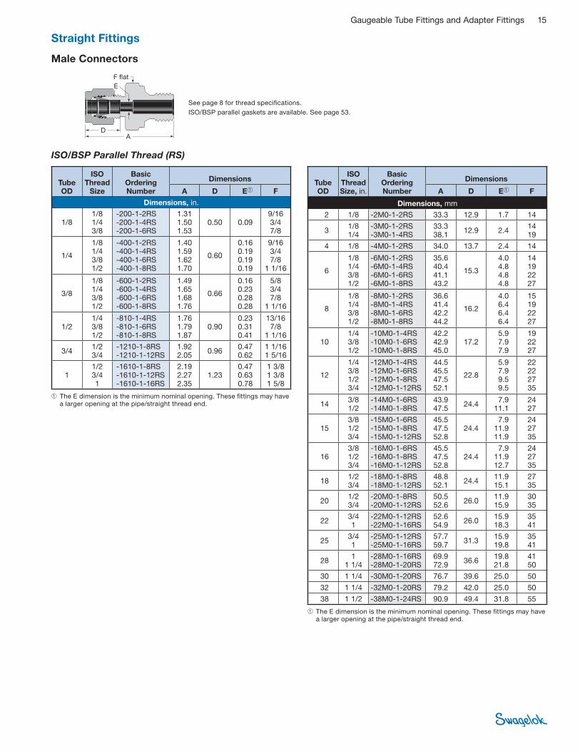
Gaugeable Tube Fittings and Adapter Fittings 15
See page 8 for thread specifi cations.
ISO/BSP parallel gaskets are available. See page 53.
Male Connectors
ISO/BSP Parallel Thread (RS)
DA
E
F fl at
➀ The E dimension is the minimum nominal opening. These fi ttings may have a larger opening at the pipe/straight thread end.
➀ The E dimension is the minimum nominal opening. These fi ttings may have a larger opening at the pipe/straight thread end.
Tube OD
ISO Thread
Size
Basic Ordering Number
Dimensions
A D E➀ F
Dimensions, in.
1/8 1/8 1/4 3/8
-200-1-2RS -200-1-4RS -200-1-6RS
1.31 1.50 1.53
0.50 0.09 9/16 3/4 7/8
1/4
1/8 1/4 3/8 1/2
-400-1-2RS -400-1-4RS -400-1-6RS -400-1-8RS
1.40 1.59 1.62 1.70
0.60
0.16 0.19 0.19 0.19
9/16 3/4 7/8
1 1/16
3/8
1/8 1/4 3/8 1/2
-600-1-2RS -600-1-4RS -600-1-6RS -600-1-8RS
1.49 1.65 1.68 1.76
0.66
0.16 0.23 0.28 0.28
5/8 3/4 7/8
1 1/16
1/2 1/4 3/8 1/2
-810-1-4RS -810-1-6RS -810-1-8RS
1.76 1.79 1.87
0.90 0.23 0.31 0.41
13/16 7/8
1 1/16
3/4 1/2 3/4
-1210-1-8RS -1210-1-12RS
1.92 2.05
0.96 0.47 0.62
1 1/16 1 5/16
1 1/2 3/4 1
-1610-1-8RS -1610-1-12RS -1610-1-16RS
2.19 2.27 2.35
1.23 0.47 0.63 0.78
1 3/8 1 3/8 1 5/8
Tube OD
ISO Thread Size, in.
Basic Ordering Number
Dimensions
A D E➀ F
Dimensions, mm
2 1/8 -2M0-1-2RS 33.3 12.9 1.7 14
3 1/8 1/4
-3M0-1-2RS -3M0-1-4RS
33.3 38.1
12.9 2.4 14 19
4 1/8 -4M0-1-2RS 34.0 13.7 2.4 14
6
1/8 1/4 3/8 1/2
-6M0-1-2RS -6M0-1-4RS -6M0-1-6RS -6M0-1-8RS
35.6 40.4 41.1 43.2
15.3
4.0 4.8 4.8 4.8
14 19 22 27
8
1/8 1/4 3/8 1/2
-8M0-1-2RS -8M0-1-4RS -8M0-1-6RS -8M0-1-8RS
36.6 41.4 42.2 44.2
16.2
4.0 6.4 6.4 6.4
15 19 22 27
10 1/4 3/8 1/2
-10M0-1-4RS -10M0-1-6RS -10M0-1-8RS
42.2 42.9 45.0
17.2 5.9 7.9 7.9
19 22 27
12
1/4 3/8 1/2 3/4
-12M0-1-4RS -12M0-1-6RS -12M0-1-8RS -12M0-1-12RS
44.5 45.5 47.5 52.1
22.8
5.9 7.9 9.5 9.5
22 22 27 35
14 3/8 1/2
-14M0-1-6RS -14M0-1-8RS
43.9 47.5
24.4 7.9
11.1 24 27
15 3/8 1/2 3/4
-15M0-1-6RS -15M0-1-8RS -15M0-1-12RS
45.5 47.5 52.8
24.4 7.9
11.9 11.9
24 27 35
16 3/8 1/2 3/4
-16M0-1-6RS -16M0-1-8RS -16M0-1-12RS
45.5 47.5 52.8
24.4 7.9
11.9 12.7
24 27 35
18 1/2 3/4
-18M0-1-8RS -18M0-1-12RS
48.8 52.1
24.4 11.9 15.1
27 35
20 1/2 3/4
-20M0-1-8RS -20M0-1-12RS
50.5 52.6
26.0 11.9 15.9
30 35
22 3/4 1
-22M0-1-12RS -22M0-1-16RS
52.6 54.9
26.0 15.9 18.3
35 41
25 3/4 1
-25M0-1-12RS -25M0-1-16RS
57.7 59.7
31.3 15.9 19.8
35 41
28 1
1 1/4 -28M0-1-16RS -28M0-1-20RS
69.9 72.9
36.6 19.8 21.8
41 50
30 1 1/4 -30M0-1-20RS 76.7 39.6 25.0 50
32 1 1/4 -32M0-1-20RS 79.2 42.0 25.0 50
38 1 1/2 -38M0-1-24RS 90.9 49.4 31.8 55
Straight Fittings
16 Gaugeable Tube Fittings and Adapter Fittings
See page 8 for thread specifications.
ISO/BSP parallel gaskets are available. See page 53.
Male Connectors
ISO/BSP Parallel Thread (RP)
DA
E
F fl at
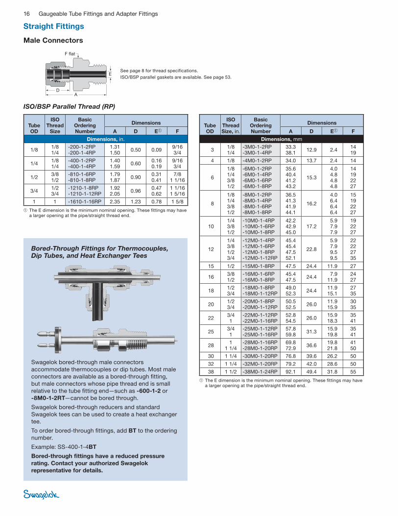
Bored-Through Fittings for Thermocouples, Dip Tubes, and Heat Exchanger Tees
Swagelok bored-through male connectors
accommodate thermocouples or dip tubes. Most male
connectors are available as a bored-through fi tting,
but male connectors whose pipe thread end is small
relative to the tube fi tting end—such as -600-1-2 or
-8M0-1-2RT—cannot be bored through.
Swagelok bored-through reducers and standard
Swagelok tees can be used to create a heat exchanger
tee.
To order bored-through fi ttings, add BT to the ordering
number.
Example: SS-400-1-4BT
Bored-through fi ttings have a reduced pressure
rating. Contact your authorized Swagelok
representative for details.
➀ The E dimension is the minimum nominal opening. These fi ttings may have a larger opening at the pipe/straight thread end.
➀ The E dimension is the minimum nominal opening. These fi ttings may have a larger opening at the pipe/straight thread end.
Tube OD
ISO Thread
Size
Basic Ordering Number
Dimensions
A D E➀ F
Dimensions, in.
1/8 1/8 1/4
-200-1-2RP -200-1-4RP
1.31 1.50
0.50 0.09 9/16 3/4
1/4 1/8 1/4
-400-1-2RP -400-1-4RP
1.40 1.59
0.60 0.16 0.19
9/16 3/4
1/2 3/8 1/2
-810-1-6RP -810-1-8RP
1.79 1.87
0.90 0.31 0.41
7/8 1 1/16
3/4 1/2 3/4
-1210-1-8RP -1210-1-12RP
1.92 2.05
0.96 0.47 0.62
1 1/16 1 5/16
1 1 -1610-1-16RP 2.35 1.23 0.78 1 5/8
Tube OD
ISO Thread Size, in.
Basic Ordering Number
Dimensions
A D E➀ F
Dimensions, mm
3 1/8 1/4
-3M0-1-2RP -3M0-1-4RP
33.3 38.1
12.9 2.4 14 19
4 1/8 -4M0-1-2RP 34.0 13.7 2.4 14
6
1/8 1/4 3/8 1/2
-6M0-1-2RP -6M0-1-4RP -6M0-1-6RP -6M0-1-8RP
35.6 40.4 41.2 43.2
15.3
4.0 4.8 4.8 4.8
14 19 22 27
8
1/8 1/4 3/8 1/2
-8M0-1-2RP -8M0-1-4RP -8M0-1-6RP -8M0-1-8RP
36.5 41.3 41.9 44.1
16.2
4.0 6.4 6.4 6.4
15 19 22 27
10 1/4 3/8 1/2
-10M0-1-4RP -10M0-1-6RP -10M0-1-8RP
42.2 42.9 45.0
17.2 5.9 7.9 7.9
19 22 27
12
1/4 3/8 1/2 3/4
-12M0-1-4RP -12M0-1-6RP -12M0-1-8RP -12M0-1-12RP
45.4 45.4 47.5 52.1
22.8
5.9 7.9 9.5 9.5
22 22 27 35
15 1/2 -15M0-1-8RP 47.5 24.4 11.9 27
16 3/8 1/2
-16M0-1-6RP -16M0-1-8RP
45.4 47.5
24.4 7.9
11.9 24 27
18 1/2 3/4
-18M0-1-8RP -18M0-1-12RP
49.0 52.3
24.4 11.9 15.1
27 35
20 1/2 3/4
-20M0-1-8RP -20M0-1-12RP
50.5 52.5
26.0 11.9 15.9
30 35
22 3/4 1
-22M0-1-12RP -22M0-1-16RP
52.8 54.5
26.0 15.9 18.3
35 41
25 3/4 1
-25M0-1-12RP -25M0-1-16RP
57.8 59.8
31.3 15.9 19.8
35 41
28 1
1 1/4 -28M0-1-16RP -28M0-1-20RP
69.8 72.9
36.6 19.8 21.8
41 50
30 1 1/4 -30M0-1-20RP 76.8 39.6 26.2 50
32 1 1/4 -32M0-1-20RP 79.2 42.0 28.6 50
38 1 1/2 -38M0-1-24RP 92.1 49.4 31.8 55
Straight Fittings

Gaugeable Tube Fittings and Adapter Fittings 17
SAE/MS Straight Thread (ST)
Adapts to SAE J1926/1 and ISO 11926-1 straight thread boss.
Male Connectors Bulkhead NPT
DA
E
F fl at
DA
E
F fl atO-ring
➀ The E dimension is the minimum nominal opening. These fi ttings may have a larger opening at the pipe/straight thread end.
➀ The E dimension is the minimum nominal opening. These fi ttings may have a larger opening at the pipe/straight thread end.
➀ The E dimension is the minimum nominal opening. These fi ttings may have a larger opening at the pipe/straight thread end.
Long SAE/MS Straight Thread
Tube OD
NPT Size in.
Basic Ordering Number
Dimensions
A D E➀ F
Panel Hole Size
Max Panel
Thickness
Dimensions, in.
1/8 1/8 -200-11-2 1.83 0.50 0.09 1/2 21/64 0.50
1/4 1/8 1/4
-400-11-2 -400-11-4
1.95 2.13
0.60 0.19 5/8 29/64 0.40
3/8 1/4 3/8 1/2
-600-11-4 -600-11-6 -600-11-8
2.26 2.26 2.51
0.66 0.28 3/4 3/4 7/8
37/64 0.44
1/2 3/8 1/2
-810-11-6 -810-11-8
2.49 2.71
0.90 0.38 0.41
15/16 49/64 0.50
3/4 3/4 -1210-11-12 3.00 0.96 0.62 1 3/16 1 1/64 0.66
1 1 -1610-11-16 3.67 1.23 0.88 1 5/8 1 21/64 0.75
Dimensions, mm
6 1/8 1/4
-6M0-11-2 -6M0-11-4
49.5 53.6
15.3 4.8 16 11.5 10.2
12 1/2 -12M0-11-8 68.8 22.8 9.5 24 19.5 12.7
Tube OD
SAE/MS Thread
Size
Basic Ordering Number
Dimensions
A D E➀ F
Dimensions, in.
1/8 5/16-24 7/16-20 9/16-18
-200-1-2ST -200-1-4ST -200-1-6ST
1.18 1.24 1.31
0.50 0.09 7/16 9/16 11/16
1/4
5/16-24 7/16-20 9/16-18 3/4-16 7/8-14
-400-1-2ST -400-1-4ST -400-1-6ST -400-1-8ST -400-1-10ST
1.27 1.34 1.40 1.48 1.60
0.60
0.09 0.19 0.19 0.19 0.19
1/2 9/16 11/16 7/8 1
5/16 1/2-20 -500-1-5ST 1.37 0.64 0.25 5/8
3/8
7/16-20 9/16-18 3/4-16 7/8-14
-600-1-4ST -600-1-6ST -600-1-8ST -600-1-10ST
1.40 1.46 1.54 1.66
0.66
0.18 0.28 0.28 0.28
5/8 11/16 7/8 1
1/2
9/16-18 3/4-16 7/8-14
1 1/16-12
-810-1-6ST -810-1-8ST -810-1-10ST -810-1-12ST
1.54 1.65 1.77 1.93
0.90
0.28 0.41 0.41 0.41
13/16 7/8 1
1 1/4
5/8 3/4-16 7/8-14
-1010-1-8ST -1010-1-10ST
1.65 1.78
0.96 0.42 0.50
15/16 1
3/4 3/4-16
1 1/16-12 1 5/16-12
-1210-1-8ST -1210-1-12ST -1210-1-16ST
1.81 1.93 1.96
0.96 0.42 0.62 0.63
1 1/16 1 1/4 1 1/2
7/8 1 3/16-12 -1410-1-14ST 1.93 1.02 0.72 1 3/8
1 1 1/16-12 1 5/16-12
-1610-1-12ST -1610-1-16ST
2.10 2.14
1.23 0.66 0.88
1 3/8 1 1/2
1 1/4 1 5/8-12 -2000-1-20ST 2.69 1.62 1.09 1 7/8
1 1/2 1 7/8-12 -2400-1-24ST 3.06 1.97 1.34 2 1/8
2 2 1/2-12 -3200-1-32ST 4.00 2.66 1.81 2 3/4
Tube OD
SAE/MS Thread
Size
Basic Ordering Number
Dimensions
A D E➀ F
Dimensions, mm
6 9/16-18 -6M0-1-6ST 35.6 15.3 4.8 18
10 9/16-18 3/4-16
-10M0-1-6ST -10M0-1-8ST
37.3 39.4
17.2 7.1 7.9
22
12 7/16-20 9/16-18 3/4-16
-12M0-1-4ST -12M0-1-6ST -12M0-1-8ST
40.6 39.9 41.9
22.8 5.2 7.1 9.5
22
➀ The E dimension is the minimum nominal opening. These fi ttings may have a larger opening at the pipe/straight thread end.
Tube OD
SAE/MS Thread
Size
Basic Ordering Number
Dimensions
A D E➀ F
Dimensions, in.
1/4 7/16-20 -400-1L-4ST 2.26 0.60 0.19 9/16
1/2 3/4-16 -810-1L-8ST 3.01 0.90 0.41 7/8
Long SAE/MS Straight Thread (ST)
Straight Fittings

18 Gaugeable Tube Fittings and Adapter Fittings
Mounting Dimensions for O-Seal Fittings
For a raised surface, see Fig. 1. The minimum diameter allows metal-to-metal contact outside of the O-ring sealing
diameter to prevent O-ring extrusion.
For a recessed hole that allows the round shoulder of the O-seal fi tting into the recess, see Fig. 2.
For a recessed hole that allows the hex of the O-seal fi tting into the recess, see Fig. 3.
1/8 in.
Fig. 3
O-Seal (SAE/MS Straight Thread) O-Seal (NPT)
➀ The E dimension is the minimum nominal opening. These fi ttings may have a larger opening at the pipe/straight thread end.
➀ The E dimension is the minimum nominal opening. These fi ttings may have a larger opening at the pipe/straight thread end.
DA
E
F fl atO-ring
DA
E
F fl atO-ring
Male Connectors
➀ Allow clearance for full thread.
➀
Fig. 1
A
➀C
E
➀B
D
Fig. 2
Tube OD
SAE/MS Thread
Size
Basic Ordering Number
Dimensions
A D E➀ F
Dimensions, in.
1/16 5/16-24 -100-1-OR 1.05 0.34 0.05 9/16
1/8 5/16-24 -200-1-OR 1.29 0.50 0.09 9/16
3/16 3/8-24 -300-1-OR 1.35 0.54 0.12 5/8
1/4 7/16-20 -400-1-OR 1.51 0.60 0.19 3/4
5/16 1/2-20 -500-1-OR 1.60 0.64 0.25 7/8
3/8 9/16-18 -600-1-OR 1.67 0.66 0.28 15/16
1/2 3/4-16 -810-1-OR 1.81 0.90 0.41 1 1/8
3/4 1 1/16-12 -1210-1-OR 2.06 0.96 0.62 1 1/2
1 1 5/16-12 -1610-1-OR 2.29 1.23 0.88 1 3/4
Tube OD
NPT Size
Basic Ordering Number
Dimensions
A D E➀ F
Dimensions, in.
1/8 1/8 -200-1-2-OR 1.29 0.50 0.09 3/4
1/4 1/8 1/4
-400-1-2-OR -400-1-4-OR
1.38 1.51
0.60 0.19 3/4
15/16
3/8 1/4 3/8 1/2
-600-1-4-OR -600-1-6-OR -600-1-8-OR
1.57 1.63 1.85
0.66 0.28 15/16 1 1/8 1 5/16
1/2 1/2 -810-1-8-OR 1.96 0.90 0.41 1 5/16
SAE/MS Thread
Size NPT Size
A Min Dia
B Min Dia
C Min Dia
D Max
Depth
E Max
Depth
Dimensions, in.
5/16-24 — 0.50 0.59 0.66 0.09
0.16
5/16-24 0.22
— 1/8 0.69 0.78 0.88 0.16 0.28
3/8-24 — 0.56 0.66 0.75 0.09 0.22
7/16-20 — 0.69 0.78 0.88
0.16
0.28— 1/8
— 1/4 0.87 0.97 1.09
0.31 1/2-20 — 0.75 0.91 1.03
9/16-18 — 0.81 0.97 1.09
— 1/4 0.87
— 3/8 1.00 1.16 1.31 0.34
— 1/2 1.22 1.34 1.53 0.22 0.44
3/4-16 — 1.00 1.16 1.31 0.16 0.34
— 1/2 1.22 1.34 1.53
0.22
0.44
1 1/16-12 — 1.41 1.53 1.75 0.50
1 5/16-12 — 1.69 1.78 2.03 0.56
Straight Fittings
Gaugeable Tube Fittings and Adapter Fittings 19
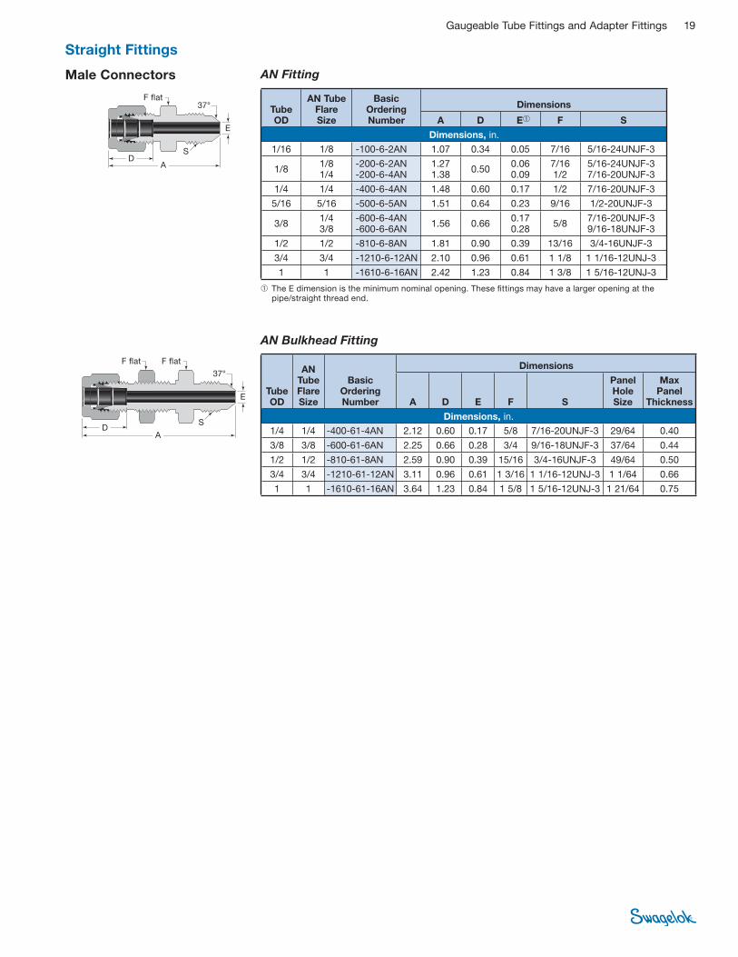
Male Connectors
➀ The E dimension is the minimum nominal opening. These fi ttings may have a larger opening at the pipe/straight thread end.
AN Bulkhead Fitting
AN Fitting
DA
E
S
F fl at F fl at
DA
E
F fl at37°
37°
S
Tube OD
AN Tube Flare Size
Basic Ordering Number
Dimensions
A D E➀ F S
Dimensions, in.
1/16 1/8 -100-6-2AN 1.07 0.34 0.05 7/16 5/16-24UNJF-3
1/8 1/8 1/4
-200-6-2AN -200-6-4AN
1.27 1.38
0.50 0.06 0.09
7/16 1/2
5/16-24UNJF-3 7/16-20UNJF-3
1/4 1/4 -400-6-4AN 1.48 0.60 0.17 1/2 7/16-20UNJF-3
5/16 5/16 -500-6-5AN 1.51 0.64 0.23 9/16 1/2-20UNJF-3
3/8 1/4 3/8
-600-6-4AN -600-6-6AN
1.56 0.66 0.17 0.28
5/8 7/16-20UNJF-3 9/16-18UNJF-3
1/2 1/2 -810-6-8AN 1.81 0.90 0.39 13/16 3/4-16UNJF-3
3/4 3/4 -1210-6-12AN 2.10 0.96 0.61 1 1/8 1 1/16-12UNJ-3
1 1 -1610-6-16AN 2.42 1.23 0.84 1 3/8 1 5/16-12UNJ-3
Tube OD
AN Tube Flare Size
Basic Ordering Number
Dimensions
A D E F S
Panel Hole Size
Max Panel
Thickness
Dimensions, in.
1/4 1/4 -400-61-4AN 2.12 0.60 0.17 5/8 7/16-20UNJF-3 29/64 0.40
3/8 3/8 -600-61-6AN 2.25 0.66 0.28 3/4 9/16-18UNJF-3 37/64 0.44
1/2 1/2 -810-61-8AN 2.59 0.90 0.39 15/16 3/4-16UNJF-3 49/64 0.50
3/4 3/4 -1210-61-12AN 3.11 0.96 0.61 1 3/16 1 1/16-12UNJ-3 1 1/64 0.66
1 1 -1610-61-16AN 3.64 1.23 0.84 1 5/8 1 5/16-12UNJ-3 1 21/64 0.75
Straight Fittings
20 Gaugeable Tube Fittings and Adapter Fittings
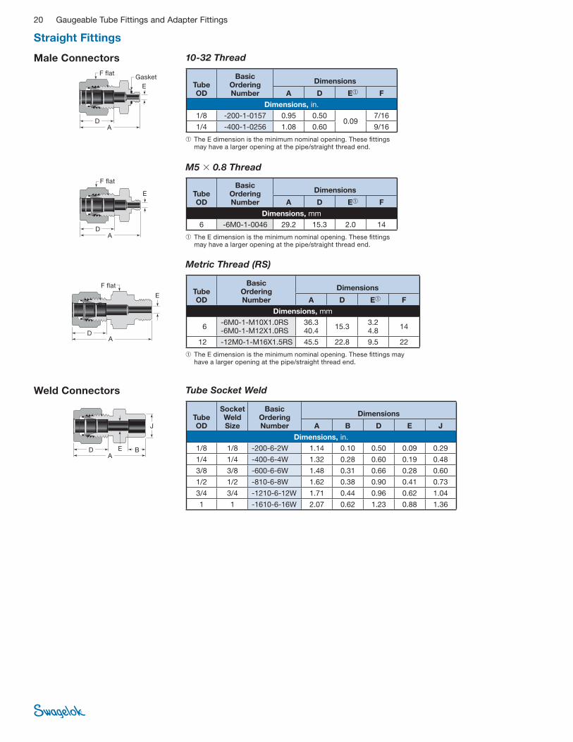
Weld Connectors Tube Socket Weld
D BA
J
E
Tube OD
Socket Weld Size
Basic Ordering Number
Dimensions
A B D E J
Dimensions, in.
1/8 1/8 -200-6-2W 1.14 0.10 0.50 0.09 0.29
1/4 1/4 -400-6-4W 1.32 0.28 0.60 0.19 0.48
3/8 3/8 -600-6-6W 1.48 0.31 0.66 0.28 0.60
1/2 1/2 -810-6-8W 1.62 0.38 0.90 0.41 0.73
3/4 3/4 -1210-6-12W 1.71 0.44 0.96 0.62 1.04
1 1 -1610-6-16W 2.07 0.62 1.23 0.88 1.36
10-32 ThreadMale Connectors
DA
E
F fl at
Tube OD
Basic Ordering Number
Dimensions
A D E➀ F
Dimensions, in.
1/8 -200-1-0157 0.95 0.50 0.09
7/16
1/4 -400-1-0256 1.08 0.60 9/16
➀ The E dimension is the minimum nominal opening. These fi ttings may have a larger opening at the pipe/straight thread end.
Gasket
M5 � 0.8 Thread
Tube OD
Basic Ordering Number
Dimensions
A D E➀ F
Dimensions, mm
6 -6M0-1-0046 29.2 15.3 2.0 14D
A
E
F fl at
➀ The E dimension is the minimum nominal opening. These fi ttings may have a larger opening at the pipe/straight thread end.
Metric Thread (RS)
E
E
F fl atTube OD
Basic Ordering Number
Dimensions
A D E➀ F
Dimensions, mm
6 -6M0-1-M10X1.0RS -6M0-1-M12X1.0RS
36.3 40.4
15.3 3.2 4.8
14
12 -12M0-1-M16X1.5RS 45.5 22.8 9.5 22
➀ The E dimension is the minimum nominal opening. These fi ttings may have a larger opening at the pipe/straight thread end.
AD
Straight Fittings
Gaugeable Tube Fittings and Adapter Fittings 21
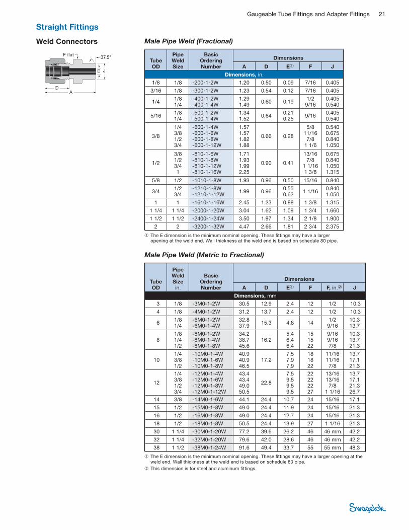
Weld Connectors
DA
E J
F fl at37.5°
Male Pipe Weld (Fractional)
➀ The E dimension is the minimum nominal opening. These fi ttings may have a larger opening at the weld end. Wall thickness at the weld end is based on schedule 80 pipe.
Tube OD
Pipe Weld Size
Basic Ordering Number
Dimensions
A D E➀ F J
Dimensions, in.
1/8 1/8 -200-1-2W 1.20 0.50 0.09 7/16 0.405
3/16 1/8 -300-1-2W 1.23 0.54 0.12 7/16 0.405
1/4 1/8 1/4
-400-1-2W -400-1-4W
1.29 1.49
0.60 0.19 1/2 9/16
0.405 0.540
5/16 1/8 1/4
-500-1-2W -500-1-4W
1.34 1.52
0.64 0.21 0.25
9/16 0.405 0.540
3/8
1/4 3/8 1/2 3/4
-600-1-4W -600-1-6W -600-1-8W -600-1-12W
1.57 1.57 1.82 1.88
0.66 0.28
5/8 11/16 7/8
1 1/6
0.540 0.675 0.840 1.050
1/2
3/8 1/2 3/4 1
-810-1-6W -810-1-8W -810-1-12W -810-1-16W
1.71 1.93 1.99 2.25
0.90
0.41
13/16 7/8
1 1/16 1 3/8
0.675 0.840 1.050 1.315
5/8 1/2 -1010-1-8W 1.93 0.96 0.50 15/16 0.840
3/4 1/2 3/4
-1210-1-8W -1210-1-12W
1.99 0.96 0.55 0.62
1 1/16 0.840 1.050
1 1 -1610-1-16W 2.45 1.23 0.88 1 3/8 1.315
1 1/4 1 1/4 -2000-1-20W 3.04 1.62 1.09 1 3/4 1.660
1 1/2 1 1/2 -2400-1-24W 3.50 1.97 1.34 2 1/8 1.900
2 2 -3200-1-32W 4.47 2.66 1.81 2 3/4 2.375
Male Pipe Weld (Metric to Fractional)
➀ The E dimension is the minimum nominal opening. These fi ttings may have a larger opening at the weld end. Wall thickness at the weld end is based on schedule 80 pipe.
➁ This dimension is for steel and aluminum fi ttings.
Tube OD
Pipe Weld Sizein.
Basic Ordering Number
Dimensions
A D E➀ F F, in.➁ J
Dimensions, mm
3 1/8 -3M0-1-2W 30.5 12.9 2.4 12 1/2 10.3
4 1/8 -4M0-1-2W 31.2 13.7 2.4 12 1/2 10.3
6 1/8 1/4
-6M0-1-2W -6M0-1-4W
32.8 37.9
15.3 4.8 14 1/2 9/16
10.3 13.7
8 1/8 1/4 1/2
-8M0-1-2W -8M0-1-4W -8M0-1-8W
34.2 38.7 45.6
16.2 5.4 6.4 6.4
15 15 22
9/16 9/16 7/8
10.3 13.7 21.3
10 1/4 3/8 1/2
-10M0-1-4W -10M0-1-6W -10M0-1-8W
40.9 40.9 46.5
17.2 7.5 7.9 7.9
18 18 22
11/16 11/16 7/8
13.7 17.1 21.3
12
1/4 3/8 1/2 3/4
-12M0-1-4W -12M0-1-6W -12M0-1-8W -12M0-1-12W
43.4 43.4 49.0 50.5
22.8
7.5 9.5 9.5 9.5
22 22 22 27
13/16 13/16 7/8
1 1/16
13.7 17.1 21.3 26.7
14 3/8 -14M0-1-6W 44.1 24.4 10.7 24 15/16 17.1
15 1/2 -15M0-1-8W 49.0 24.4 11.9 24 15/16 21.3
16 1/2 -16M0-1-8W 49.0 24.4 12.7 24 15/16 21.3
18 1/2 -18M0-1-8W 50.5 24.4 13.9 27 1 1/16 21.3
30 1 1/4 -30M0-1-20W 77.2 39.6 26.2 46 46 mm 42.2
32 1 1/4 -32M0-1-20W 79.6 42.0 28.6 46 46 mm 42.2
38 1 1/2 -38M0-1-24W 91.6 49.4 33.7 55 55 mm 48.3
Straight Fittings
22 Gaugeable Tube Fittings and Adapter Fittings
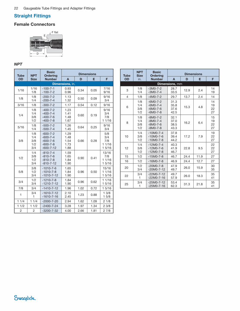
Female Connectors
NPT
AD
EF fl at
Tube OD
NPT Size
Basic Ordering Number
Dimensions
A D E F
Dimensions, in.
1/16 1/16 1/8
-100-7-1 -100-7-2
0.93 0.96
0.34 0.05 7/16 9/16
1/8 1/8 1/4
-200-7-2 -200-7-4
1.13 1.32
0.50 0.09 9/16 3/4
3/16 1/8 -300-7-2 1.17 0.54 0.12 9/16
1/4
1/8 1/4 3/8 1/2
-400-7-2 -400-7-4 -400-7-6 -400-7-8
1.23 1.41 1.48 1.67
0.60 0.19
9/16 3/4 7/8
1 1/16
5/16 1/8 1/4
-500-7-2 -500-7-4
1.26 1.45
0.64 0.25 9/16 3/4
3/8
1/8 1/4 3/8 1/2 3/4
-600-7-2 -600-7-4 -600-7-6 -600-7-8 -600-7-12
1.29 1.48 1.54 1.73 1.88
0.66 0.28
5/8 3/47/8
1 1/16 1 5/16
1/2
1/4 3/8 1/2 3/4
-810-7-4 -810-7-6 -810-7-8 -810-7-12
1.59 1.65 1.84 1.90
0.90 0.41
13/16 7/8
1 1/16 1 5/16
5/8 3/8 1/2 3/4
-1010-7-6 -1010-7-8 -1010-7-12
1.65 1.84 1.90
0.96 0.50 15/16 1 1/16 1 5/16
3/4 1/2 3/4
-1210-7-8 -1210-7-12
1.84 1.90
0.96 0.62 1 1/16 1 5/16
7/8 3/4 -1410-7-12 1.96 1.02 0.72 1 5/16
1 3/4 1
-1610-7-12 -1610-7-16
2.10 2.45
1.23 0.88 1 3/8 1 5/8
1 1/4 1 1/4 -2000-7-20 2.94 1.62 1.09 2 1/8
1 1/2 1 1/2 -2400-7-24 3.28 1.97 1.34 2 3/8
2 2 -3200-7-32 4.00 2.66 1.81 2 7/8
Tube OD
NPT Sizein.
Basic Ordering Number
Dimensions
A D E F
Dimensions, mm
3 1/8 1/4
-3M0-7-2 -3M0-7-4
28.7 33.5
12.9 2.4 14 19
4 1/8 -4M0-7-2 29.7 13.7 2.4 14
6
1/8 1/4 3/8 1/2
-6M0-7-2 -6M0-7-4 -6M0-7-6 -6M0-7-8
31.3 35.8 37.6 42.5
15.3 4.8
14 19 22 27
8
1/8 1/4 3/8 1/2
-8M0-7-2 -8M0-7-4 -8M0-7-6 -8M0-7-8
32.1 37.0 38.5 43.3
16.2 6.4
15 19 22 27
10 1/4 3/8 1/2
-10M0-7-4 -10M0-7-6 -10M0-7-8
37.8 39.4 44.2
17.2 7.9 19 22 27
12 1/4 3/8 1/2
-12M0-7-4 -12M0-7-6 -12M0-7-8
40.3 41.9 46.7
22.8 9.5 22 22 27
15 1/2 -15M0-7-8 46.7 24.4 11.9 27
16 1/2 -16M0-7-8 46.9 24.4 12.7 27
20 1/2 3/4
-20M0-7-8 -20M0-7-12
47.9 49.7
26.0 15.9 30 35
22 3/4 1
-22M0-7-12 -22M0-7-16
49.7 57.9
26.0 18.3 35 41
25 3/4 1
-25M0-7-12 -25M0-7-16
53.4 62.3
31.3 21.8 35 41
Straight Fittings
Gaugeable Tube Fittings and Adapter Fittings 23
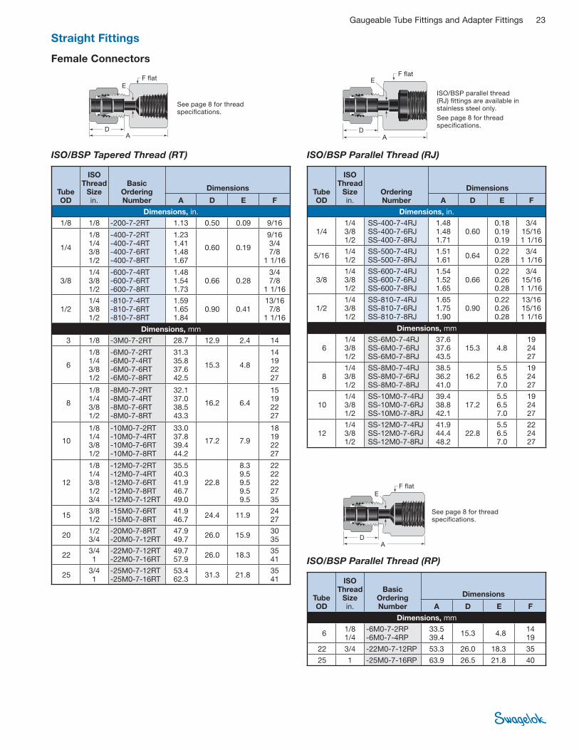
Female Connectors
ISO/BSP Parallel Thread (RJ)
AD
EF fl at
AD
EF fl at
See page 8 for thread specifi cations.
ISO/BSP parallel thread (RJ) fi ttings are available in stainless steel only.
See page 8 for thread specifi cations.
See page 8 for thread specifi cations.
ISO/BSP Parallel Thread (RP)
AD
EF fl at
ISO/BSP Tapered Thread (RT)
Tube OD
ISO Thread
Size in.
Basic Ordering Number
Dimensions
A D E F
Dimensions, in.
1/8 1/8 -200-7-2RT 1.13 0.50 0.09 9/16
1/4
1/8 1/4 3/8 1/2
-400-7-2RT -400-7-4RT -400-7-6RT -400-7-8RT
1.23 1.41 1.48 1.67
0.60 0.19
9/16 3/4 7/8
1 1/16
3/8 1/4 3/8 1/2
-600-7-4RT -600-7-6RT -600-7-8RT
1.48 1.54 1.73
0.66 0.28 3/4 7/8
1 1/16
1/2 1/4 3/8 1/2
-810-7-4RT -810-7-6RT -810-7-8RT
1.59 1.65 1.84
0.90 0.41 13/16 7/8
1 1/16
Dimensions, mm
3 1/8 -3M0-7-2RT 28.7 12.9 2.4 14
6
1/8 1/4 3/8 1/2
-6M0-7-2RT -6M0-7-4RT -6M0-7-6RT -6M0-7-8RT
31.3 35.8 37.6 42.5
15.3 4.8
14 19 22 27
8
1/8 1/4 3/8 1/2
-8M0-7-2RT -8M0-7-4RT -8M0-7-6RT -8M0-7-8RT
32.1 37.0 38.5 43.3
16.2 6.4
15 19 22 27
10
1/8 1/4 3/8 1/2
-10M0-7-2RT -10M0-7-4RT -10M0-7-6RT -10M0-7-8RT
33.0 37.8 39.4 44.2
17.2 7.9
18 19 22 27
12
1/8 1/4 3/8 1/2 3/4
-12M0-7-2RT -12M0-7-4RT -12M0-7-6RT -12M0-7-8RT -12M0-7-12RT
35.5 40.3 41.9 46.7 49.0
22.8
8.3 9.5 9.5 9.5 9.5
22 22 22 27 35
15 3/8 1/2
-15M0-7-6RT -15M0-7-8RT
41.9 46.7
24.4 11.9 24 27
20 1/2 3/4
-20M0-7-8RT -20M0-7-12RT
47.9 49.7
26.0 15.9 30 35
22 3/4 1
-22M0-7-12RT -22M0-7-16RT
49.7 57.9
26.0 18.3 35 41
25 3/4 1
-25M0-7-12RT -25M0-7-16RT
53.4 62.3
31.3 21.8 35 41
Tube OD
ISO Thread
Size in.
Ordering Number
Dimensions
A D E F
Dimensions, in.
1/4 1/4 3/8 1/2
SS-400-7-4RJ SS-400-7-6RJ SS-400-7-8RJ
1.48 1.48 1.71
0.60 0.18 0.19 0.19
3/4 15/16 1 1/16
5/161/41/2
SS-500-7-4RJ SS-500-7-8RJ
1.51 1.61
0.64 0.22 0.28
3/4 1 1/16
3/8 1/4 3/8 1/2
SS-600-7-4RJ SS-600-7-6RJ SS-600-7-8RJ
1.54 1.52 1.65
0.66 0.22 0.26 0.28
3/4 15/16 1 1/16
1/2 1/4 3/8 1/2
SS-810-7-4RJ SS-810-7-6RJ SS-810-7-8RJ
1.65 1.75 1.90
0.90 0.22 0.26 0.28
13/16 15/16 1 1/16
Dimensions, mm
6 1/4 3/8 1/2
SS-6M0-7-4RJ SS-6M0-7-6RJ SS-6M0-7-8RJ
37.6 37.6 43.5
15.3 4.8 19 24 27
8 1/4 3/8 1/2
SS-8M0-7-4RJ SS-8M0-7-6RJ SS-8M0-7-8RJ
38.5 36.241.0
16.2 5.5 6.5 7.0
19 24 27
10 1/4 3/8 1/2
SS-10M0-7-4RJ SS-10M0-7-6RJ SS-10M0-7-8RJ
39.4 38.842.1
17.2 5.5 6.5 7.0
19 24 27
12 1/4 3/8 1/2
SS-12M0-7-4RJ SS-12M0-7-6RJ SS-12M0-7-8RJ
41.9 44.4 48.2
22.8 5.5 6.5 7.0
22 24 27
Tube OD
ISO Thread
Size in.
Basic Ordering Number
Dimensions
A D E F
Dimensions, mm
6 1/8 1/4
-6M0-7-2RP -6M0-7-4RP
33.5 39.4
15.3 4.8 14 19
22 3/4 -22M0-7-12RP 53.3 26.0 18.3 35
25 1 -25M0-7-16RP 63.9 26.5 21.8 40
Straight Fittings
24 Gaugeable Tube Fittings and Adapter Fittings
See page 8 for thread specifi cations.
ISO/BSP parallel gaskets are available. See page 53.
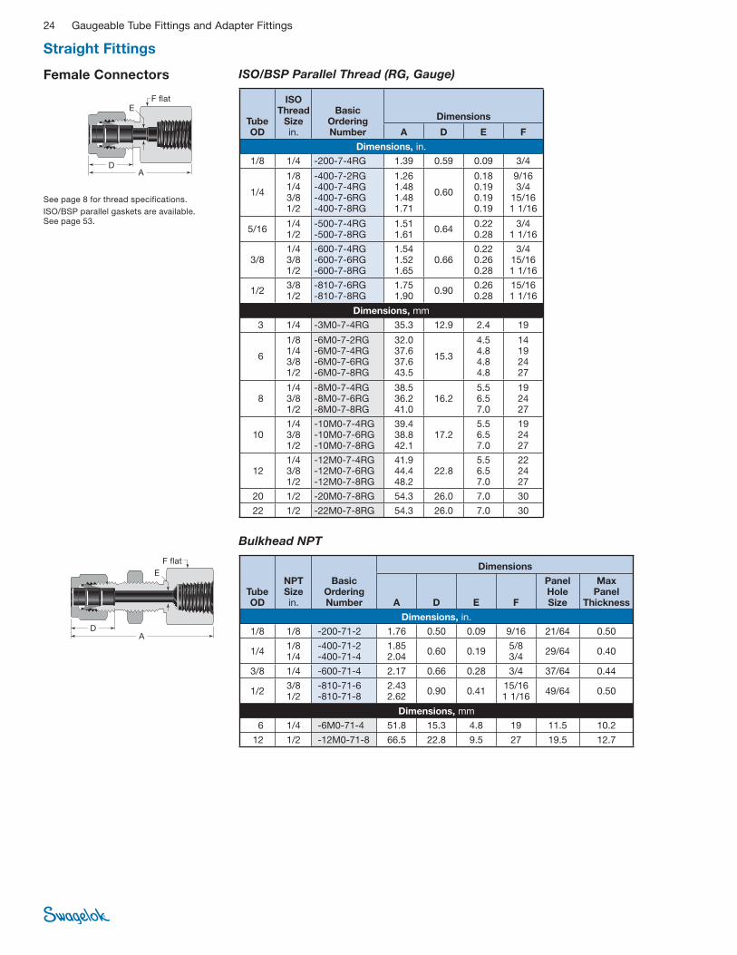
Female Connectors ISO/BSP Parallel Thread (RG, Gauge)
AD
EF fl at
Tube OD
ISO Thread
Size in.
Basic Ordering Number
Dimensions
A D E F
Dimensions, in.
1/8 1/4 -200-7-4RG 1.39 0.59 0.09 3/4
1/4
1/8 1/4 3/8 1/2
-400-7-2RG -400-7-4RG -400-7-6RG -400-7-8RG
1.26 1.48 1.48 1.71
0.60
0.18 0.19 0.19 0.19
9/16 3/4
15/16 1 1/16
5/16 1/4 1/2
-500-7-4RG -500-7-8RG
1.51 1.61
0.64 0.22 0.28
3/4 1 1/16
3/8 1/4 3/8 1/2
-600-7-4RG -600-7-6RG -600-7-8RG
1.54 1.52 1.65
0.66 0.22 0.26 0.28
3/4 15/16 1 1/16
1/2 3/8 1/2
-810-7-6RG -810-7-8RG
1.75 1.90
0.90 0.26 0.28
15/16 1 1/16
Dimensions, mm
3 1/4 -3M0-7-4RG 35.3 12.9 2.4 19
6
1/8 1/4 3/8 1/2
-6M0-7-2RG -6M0-7-4RG -6M0-7-6RG -6M0-7-8RG
32.0 37.6 37.6 43.5
15.3
4.5 4.8 4.8 4.8
14 19 24 27
8 1/4 3/8 1/2
-8M0-7-4RG -8M0-7-6RG -8M0-7-8RG
38.5 36.2 41.0
16.2 5.5 6.5 7.0
19 24 27
10 1/4 3/8 1/2
-10M0-7-4RG -10M0-7-6RG -10M0-7-8RG
39.4 38.8 42.1
17.2 5.5 6.5 7.0
19 24 27
12 1/4 3/8 1/2
-12M0-7-4RG -12M0-7-6RG -12M0-7-8RG
41.9 44.4 48.2
22.8 5.5 6.5 7.0
22 24 27
20 1/2 -20M0-7-8RG 54.3 26.0 7.0 30
22 1/2 -22M0-7-8RG 54.3 26.0 7.0 30
Bulkhead NPT
AD
E
F fl at
Tube OD
NPT Sizein.
Basic Ordering Number
Dimensions
A D E F
Panel Hole Size
Max Panel
Thickness
Dimensions, in.
1/8 1/8 -200-71-2 1.76 0.50 0.09 9/16 21/64 0.50
1/4 1/8 1/4
-400-71-2 -400-71-4
1.85 2.04
0.60 0.19 5/8 3/4
29/64 0.40
3/8 1/4 -600-71-4 2.17 0.66 0.28 3/4 37/64 0.44
1/2 3/8 1/2
-810-71-6 -810-71-8
2.43 2.62
0.90 0.41 15/16 1 1/16
49/64 0.50
Dimensions, mm
6 1/4 -6M0-71-4 51.8 15.3 4.8 19 11.5 10.2
12 1/2 -12M0-71-8 66.5 22.8 9.5 27 19.5 12.7
Straight Fittings
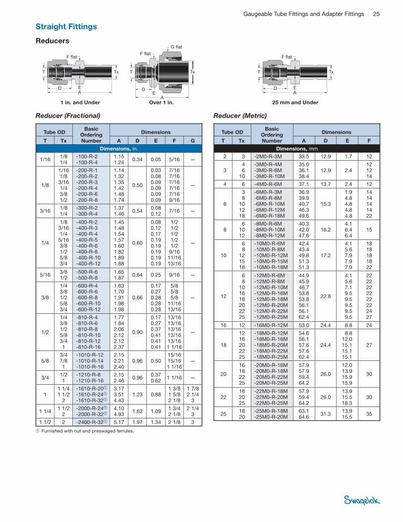
Gaugeable Tube Fittings and Adapter Fittings 25
Reducer (Metric)
AD E
T Tx
F fl at
Reducers
➀ Furnished with nut and preswaged ferrules.
1 in. and Under 25 mm and UnderOver 1 in.
Reducer (Fractional)
AD E
T Tx
F fl at
A
DE
T Tx
F fl at
G fl at
Tube OD Basic
Ordering Number
Dimensions
T Tx A D E F G
Dimensions, in.
1/16 1/8 1/4
-100-R-2 -100-R-4
1.15 1.24
0.34 0.05 5/16 —
1/8
1/16 1/8 3/16 1/4 3/8 1/2
-200-R-1 -200-R-2 -200-R-3 -200-R-4 -200-R-6 -200-R-8
1.14 1.32 1.35 1.42 1.48 1.74
0.50
0.03 0.08 0.09 0.09 0.09 0.09
7/16 7/16 7/16 7/16 7/16 9/16
—
3/16 1/8 1/4
-300-R-2 -300-R-4
1.37 1.46
0.54 0.08 0.12
7/16 —
1/4
1/8 3/16 1/4 5/16 3/8 1/2 5/8 3/4
-400-R-2 -400-R-3 -400-R-4 -400-R-5 -400-R-6 -400-R-8 -400-R-10 -400-R-12
1.45 1.48 1.54 1.57 1.60 1.82 1.89 1.88
0.60
0.08 0.12 0.17 0.19 0.19 0.19 0.19 0.19
1/2 1/2 1/2 1/2 1/2 9/16 11/16 13/16
—
5/16 3/8 1/2
-500-R-6 -500-R-8
1.65 1.87
0.64 0.25 9/16 —
3/8
1/4 3/8 1/2 5/8 3/4
-600-R-4 -600-R-6 -600-R-8 -600-R-10 -600-R-12
1.63 1.70 1.91 1.98 1.98
0.66
0.17 0.27 0.28 0.28 0.28
5/8 5/8 5/8
11/16 13/16
—
1/2
1/4 3/8 1/2 5/8 3/4 1
-810-R-4 -810-R-6 -810-R-8 -810-R-10 -810-R-12 -810-R-16
1.77 1.84 2.06 2.12 2.12 2.37
0.90
0.17 0.27 0.37 0.41 0.41 0.41
13/16 13/16 13/16 13/16 13/16 1 1/16
—
5/8 3/4 7/8 1
-1010-R-12 -1010-R-14 -1010-R-16
2.15 2.21 2.40
0.96 0.50 15/16 15/16 1 1/16
—
3/4 1/21
-1210-R-8-1210-R-16
2.152.46
0.96 0.37 0.62
1 1/16 —
1 1 1/4 1 1/2
2
-1610-R-20➀ -1610-R-24➀ -1610-R-32➀
3.17 3.51 4.43
1.23 0.88 1 3/8 1 5/8 2 1/8
1 7/8 2 1/4
3
1 1/4 1 1/2
2 -2000-R-24➀ -2000-R-32➀
4.10 4.93
1.62 1.09 1 3/4 2 1/8
2 1/4 3
1 1/2 2 -2400-R-32➀ 5.17 1.97 1.34 2 1/8 3
Tube OD Basic
Ordering Number
Dimensions
T Tx A D E F
Dimensions, mm
2 3 -2M0-R-3M 33.5 12.9 1.7 12
3 4 6
10
-3M0-R-4M -3M0-R-6M -3M0-R-10M
35.0 36.1 38.4
12.9 2.4 12 12 14
4 6 -4M0-R-6M 37.1 13.7 2.4 12
6
3 8
10 12 18
-6M0-R-3M -6M0-R-8M -6M0-R-10M -6M0-R-12M -6M0-R-18M
36.9 39.9 40.7 46.3 49.6
15.3
1.9 4.8 4.8 4.8 4.8
14 14 14 14 22
8 6
10 12
-8M0-R-6M -8M0-R-10M -8M0-R-12M
40.3 42.0 47.6
16.2 4.1 6.4 6.4
15
10
6 8
12 15 18
-10M0-R-6M -10M0-R-8M -10M0-R-12M -10M0-R-15M -10M0-R-18M
42.4 43.4 49.8 51.3 51.3
17.2
4.1 5.6 7.9 7.9 7.9
18 18 18 18 22
12
6 8
10 16 18 20 22 25
-12M0-R-6M -12M0-R-8M -12M0-R-10M -12M0-R-16M -12M0-R-18M -12M0-R-20M -12M0-R-22M -12M0-R-25M
44.9 45.9 46.7 53.8 53.8 56.1 56.1 62.4
22.8
4.1 5.6 7.1 9.5 9.5 9.5 9.5 9.5
22 22 22 22 22 22 24 27
16 12 -16M0-R-12M 53.0 24.4 8.8 24
18
12 16 20 22 25
-18M0-R-12M -18M0-R-16M -18M0-R-20M -18M0-R-22M -18M0-R-25M
54.6 56.1 57.6 57.6 62.4
24.4
8.8 12.0 15.1 15.1 15.1
27
20
16 18 22 25
-20M0-R-16M -20M0-R-18M -20M0-R-22M -20M0-R-25M
57.9 57.9 59.4 64.2
26.0
12.0 13.9 15.9 15.9
30
22 18 20 25
-22M0-R-18M -22M0-R-20M -22M0-R-25M
57.9 59.4 64.2
26.0 13.9 15.5 18.3
30
25 18 20
-25M0-R-18M -25M0-R-20M
63.1 64.6
31.3 13.9 15.5
35
Straight Fittings

26 Gaugeable Tube Fittings and Adapter Fittings
Reducers
AD E
T Tx
F fl at
AD E
T Tx
F fl at
Reducer (Metric to Fractional) Reducer (Fractional to Metric)
Tube OD Basic
Ordering Number
Dimensions
T Tx, mm A D E F
Dimensions, in.
1/8 6 -200-R-6M 1.42 0.50 0.09 7/16
Tube OD Basic
Ordering Number
Dimensions
T Tx, in. A D E F
Dimensions, mm
2 1/8 -2M0-R-2 33.5 12.9 1.7 12
3 1/8 1/4
-3M0-R-2 -3M0-R-4
33.5 36.1
12.9 2.02.4
12
4 1/4 -4M0-R-4 37.1 13.7 2.4 12
6
1/8 1/4
5/16 3/8 1/2
-6M0-R-2 -6M0-R-4 -6M0-R-5 -6M0-R-6 -6M0-R-8
36.9 39.2 39.9 40.7 46.3
15.3
2.0 4.4 4.8 4.8 4.8
14
8 1/4 3/8 1/2
-8M0-R-4 -8M0-R-6 -8M0-R-8
40.3 42.0 47.6
16.2 4.4 6.4 6.4
15
10 3/8 1/2
-10M0-R-6 -10M0-R-8
44.2 49.8
17.2 6.8 7.9
18
12 1/2 3/4
-12M0-R-8 -12M0-R-12
52.3 53.8
22.8 9.3 9.5
22
18 3/4 1
-18M0-R-12 -18M0-R-16
56.1 62.4
24.4 14.7 15.1
27
25 1 -25M0-R-16 69.5 31.3 20.2 35
Long Reducer
Use only long reducers in female Swagelok end connections.AD
ET
F fl at
Tx
Tube OD Basic
Ordering Number
Dimensions
T Tx A D E F
Dimensions, in.
3/8 1/2 -600-RF-8 2.57 0.66 0.25 5/8
Bulkhead Reducer
AD
E
F fl at F fl at
Tube OD
Basic Ordering Number
Dimensions
A D E F
Panel Hole Size
Max Panel
Thickness
Dimensions, in.
1/8 -200-R1-2 1.95 0.50 0.08 1/2 21/64 0.50
1/4 -400-R1-4 2.20 0.60 0.17 5/8 29/64 0.40
3/8 -600-R1-6 2.41 0.66 0.27 3/4 37/64 0.44
1/2 -810-R1-8 2.87 0.90 0.37 15/16 49/64 0.50
5/8 -1010-R1-10 2.96 0.96 0.47 1 1/16 57/64 0.50
3/4 -1210-R1-12 3.21 0.96 0.58 1 3/16 1 1/64 0.66
1 -1610-R1-16 3.95 1.23 0.80 1 5/8 1 21/64 0.75
Straight Fittings

Gaugeable Tube Fittings and Adapter Fittings 27
Port Connectors Port Connector
H
E
H
E
➀ Furnished with nuts and preswaged ferrules.
➀ Furnished with nuts and preswaged ferrules.
1 in./25 mm and under
Over 1 in./25mm
Tube OD
Basic Ordering Number
Dimensions
E H
Dimensions, in.
1/16 -101-PC 0.03 0.54
1/8 -201-PC 0.08 0.88
1/4 -401-PC 0.17 0.98
5/16 -501-PC 0.22 1.02
3/8 -601-PC 0.27 1.05
1/2 -811-PC 0.37 1.43
5/8 -1011-PC 0.47 1.49
3/4 -1211-PC 0.58 1.49
1 -1611-PC 0.80 1.94
1 1/4 -2000-PC➀ 1.02 2.72
1 1/2 -2400-PC➀ 1.25 3.31
2 -3200-PC➀ 1.72 4.56
Tube OD
Basic Ordering Number
Dimensions
E H
Dimensions, mm
3 -3M1-PC 1.9 22.2
6 -6M1-PC 4.1 25.0
8 -8M1-PC 5.6 26.0
10 -10M1-PC 7.1 27.1
12 -12M1-PC 8.8 36.2
15 -15M1-PC 11.2 37.8
16 -16M1-PC 12.0 37.8
18 -18M1-PC 13.9 37.8
20 -20M1-PC 15.5 39.4
25 -25M1-PC 19.9 49.3
28 -28M0-PC➀ 22.5 63.5
30 -30M0-PC➀ 24.3 67.6
32 -32M0-PC➀ 26.5 69.7
38 -38M0-PC➀ 31.6 81.9
Reducing Port Connector
H
T TxE
Tube OD Basic
Ordering Number
Dimensions
T Tx E H
Dimensions, in.
1/8 1/16 -201-PC-1 0.03 0.72
1/4 1/16 1/8
-401-PC-1 -401-PC-2
0.03 0.08
0.75 0.90
3/8 1/8 1/4
-601-PC-2 -601-PC-4
0.08 0.17
0.92 1.00
1/2 1/4 3/8
-811-PC-4 -811-PC-6
0.17 0.27
1.17 1.21
3/4 1/2 -1211-PC-8 0.37 1.49
1 1/2 3/4
-1611-PC-8 -1611-PC-12
0.37 0.58
1.69 1.72
Tube OD Basic
Ordering Number
Dimensions
T Tx E H
Dimensions, mm
6 3 -6M1-PC-3M 1.9 22.9
8 6 -8M1-PC-6M 4.1 25.4
10 6 8
-10M1-PC-6M -10M1-PC-8M
4.1 5.6
25.8 26.3
12 6 8
10
-12M1-PC-6M -12M1-PC-8M -12M1-PC-10M
4.1 5.6 7.1
29.6 30.1 30.6
16 12 -16M1-PC-12M 8.8 37.5
28 25 -28M1-PC-25M 19.8 56.5
32 25 -32M1-PC-25M 19.8 60.3
38 25 -38M1-PC-25M 19.8 65.8
Straight Fittings

28 Gaugeable Tube Fittings and Adapter Fittings
Caps and Plugs
Cap Plug
AD
Tube OD
Basic Ordering Number A D
Dimensions, in.
1/16 -100-C 0.59 0.34
1/8 -200-C 0.79 0.50
3/16 -300-C 0.84 0.54
1/4 -400-C 0.92 0.60
5/16 -500-C 0.96 0.64
3/8 -600-C 1.01 0.66
1/2 -810-C 1.21 0.90
5/8 -1010-C 1.24 0.96
3/4 -1210-C 1.27 0.96
7/8 -1410-C 1.37 1.02
1 -1610-C 1.61 1.23
1 1/8 -1810-C 1.61 1.23
1 1/4 -2000-C 2.10 1.62
1 1/2 -2400-C 2.54 1.97
2 -3200-C 3.41 2.66
Tube OD
Basic Ordering Number A D
Dimensions, mm
2 -2M0-C 20.1 12.9
3 -3M0-C 20.1 12.9
4 -4M0-C 21.3 13.7
6 -6M0-C 23.1 15.3
8 -8M0-C 24.5 16.2
10 -10M0-C 26.6 17.2
12 -12M0-C 30.6 22.8
14 -14M0-C 31.4 24.4
15 -15M0-C 31.4 24.4
16 -16M0-C 31.4 24.4
18 -18M0-C 32.2 24.4
20 -20M0-C 34.8 26.0
22 -22M0-C 34.8 26.0
25 -25M0-C 41.0 31.3
28 -28M0-C 48.5 36.6
30 -30M0-C 53.4 39.6
32 -32M0-C 55.8 42.0
38 -38M0-C 65.4 49.4
Tube OD
BasicOrdering Number
Dimensions, in.
1/16 -100-P
1/8 -200-P
3/16 -300-P
1/4 -400-P
5/16 -500-P
3/8 -600-P
1/2 -810-P
5/8 -1010-P
3/4 -1210-P
7/8 -1410-P
1 -1610-P
1 1/4 -2000-P
1 1/2 -2400-P
2 -3200-P
Tube OD
Basic Ordering Number
Dimensions, mm
2 -2M0-P
3 -3M0-P
4 -4M0-P
6 -6M0-P
8 -8M0-P
10 -10M0-P
12 -12M0-P
15 -15M0-P
16 -16M0-P
18 -18M0-P
20 -20M0-P
22 -22M0-P
25 -25M0-P
28 -28M0-P
30 -30M0-P
32 -32M0-P
38 -38M0-P
40 mesh 300 series stainless steel
wire screen assembly
Vent Protectors Mud Dauber
Swagelok vent protectors, more commonly
known as mud dauber fi ttings, protect open
ends of instruments, tubing, outlet vents, and
bleed-off lines.
The mesh wire screen prevents foreign objects,
such as mud dauber insects, from entering and
clogging various systems and causing damage.
Vent protectors are available in stainless steel
and brass. To order brass, replace SS in the
ordering number with B.
Example: B-MD-2
40 mesh wire
screen
A
E
F fl at
NPT Size
Ordering Number A E F
Dimensions, in.
1/8 SS-MD-2 0.56 0.19 1/2
1/4 SS-MD-4 0.78 0.28 9/16
3/8 SS-MD-6 0.81 0.41 11/16
1/2 SS-MD-8 1.03 0.50 7/8
3/4 SS-MD-12 1.06 0.72 1 1/16
Straight Fittings
Gaugeable Tube Fittings and Adapter Fittings 29
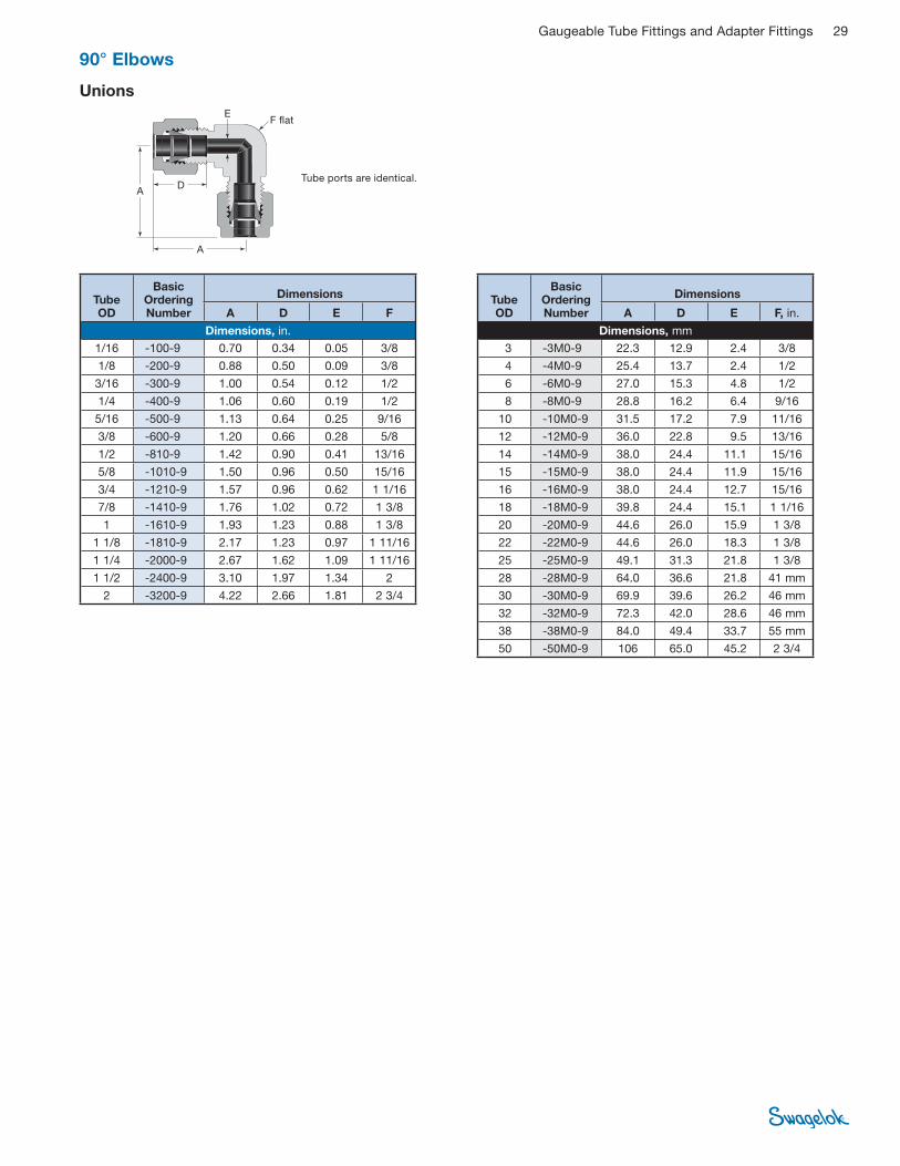
90° Elbows
Unions
Tube ports are identical.D
A
A
EF fl at
Tube OD
Basic Ordering Number
Dimensions
A D E F
Dimensions, in.
1/16 -100-9 0.70 0.34 0.05 3/8
1/8 -200-9 0.88 0.50 0.09 3/8
3/16 -300-9 1.00 0.54 0.12 1/2
1/4 -400-9 1.06 0.60 0.19 1/2
5/16 -500-9 1.13 0.64 0.25 9/16
3/8 -600-9 1.20 0.66 0.28 5/8
1/2 -810-9 1.42 0.90 0.41 13/16
5/8 -1010-9 1.50 0.96 0.50 15/16
3/4 -1210-9 1.57 0.96 0.62 1 1/16
7/8 -1410-9 1.76 1.02 0.72 1 3/8
1 -1610-9 1.93 1.23 0.88 1 3/8
1 1/8 -1810-9 2.17 1.23 0.97 1 11/16
1 1/4 -2000-9 2.67 1.62 1.09 1 11/16
1 1/2 -2400-9 3.10 1.97 1.34 2
2 -3200-9 4.22 2.66 1.81 2 3/4
Tube OD
Basic Ordering Number
Dimensions
A D E F, in.
Dimensions, mm
3 -3M0-9 22.3 12.9 2.4 3/8
4 -4M0-9 25.4 13.7 2.4 1/2
6 -6M0-9 27.0 15.3 4.8 1/2
8 -8M0-9 28.8 16.2 6.4 9/16
10 -10M0-9 31.5 17.2 7.9 11/16
12 -12M0-9 36.0 22.8 9.5 13/16
14 -14M0-9 38.0 24.4 11.1 15/16
15 -15M0-9 38.0 24.4 11.9 15/16
16 -16M0-9 38.0 24.4 12.7 15/16
18 -18M0-9 39.8 24.4 15.1 1 1/16
20 -20M0-9 44.6 26.0 15.9 1 3/8
22 -22M0-9 44.6 26.0 18.3 1 3/8
25 -25M0-9 49.1 31.3 21.8 1 3/8
28 -28M0-9 64.0 36.6 21.8 41 mm
30 -30M0-9 69.9 39.6 26.2 46 mm
32 -32M0-9 72.3 42.0 28.6 46 mm
38 -38M0-9 84.0 49.4 33.7 55 mm
50 -50M0-9 106 65.0 45.2 2 3/4

30 Gaugeable Tube Fittings and Adapter Fittings
Male
NPT
D
A
EF fl at
➀ The E dimension is the minimum nominal opening. These fi ttings may have a larger opening at the pipe/straight thread end.
➀ The E dimension is the minimum nominal opening. These fi ttings may have a larger opening at the pipe/straight thread end.
Tube OD
NPT Size
Basic Ordering Number
Dimensions
A D E➀ F
Dimensions, in.
1/16 1/16 1/8
-100-2-1 -100-2-2
0.75 0.34 0.05 7/16
1/8 1/16 1/8 1/4
-200-2-1 -200-2-2 -200-2-4
0.93 0.93 0.97
0.50
0.09
7/16 7/16 1/2
3/16 1/8 1/4
-300-2-2 -300-2-4
1.00 0.54 0.12 1/2
1/4
1/16 1/8 1/4 3/8 1/2
-400-2-1 -400-2-2 -400-2-4 -400-2-6 -400-2-8
1.06 1.06 1.06 1.17 1.25
0.60
0.12 0.19 0.19 0.19 0.19
1/2 1/2 1/2
11/16 13/16
5/16 1/8 1/4 3/8
-500-2-2 -500-2-4 -500-2-6
1.13 1.13 1.20
0.64 0.19 0.25 0.25
9/16 9/16 11/16
3/8
1/8 1/4 3/8 1/2 3/4
-600-2-2 -600-2-4 -600-2-6 -600-2-8 -600-2-12
1.20 1.20 1.23 1.31 1.46
0.66
0.19 0.28 0.28 0.28 0.28
5/8 5/8
11/16 13/16 1 1/16
1/2
1/4 3/8 1/2 3/4
-810-2-4 -810-2-6 -810-2-8 -810-2-12
1.42 1.42 1.42 1.57
0.90
0.28 0.38 0.41 0.41
13/16 13/16 13/16 1 1/16
5/8 3/8 1/2 3/4
-1010-2-6 -1010-2-8 -1010-2-12
1.50 1.50 1.57
0.96 0.38 0.47 0.50
15/16 15/16 1 1/16
3/4 1/2 3/4
-1210-2-8 -1210-2-12
1.57 0.96 0.47 0.62
1 1/16
7/8 3/4 -1410-2-12 1.76 1.02 0.62 1 3/8
1 3/4 1
-1610-2-12 -1610-2-16
1.93 1.23 0.62 0.88
1 3/8
1 1/4 1 1/4 -2000-2-20 2.67 1.62 1.09 1 11/16
1 1/2 1 1/2 -2400-2-24 3.10 1.97 1.34 2
2 2 -3200-2-32 4.22 2.66 1.81 2 3/4
Tube OD
NPT Size in.
Basic Ordering Number
Dimensions
A D E➀ F, in.
Dimensions, mm
3 1/8 1/4
-3M0-2-2 -3M0-2-4
23.6 24.6
12.9 2.4 7/16 1/2
4 1/8 1/4
-4M0-2-2 -4M0-2-4
25.4 13.7 2.4 1/2
6
1/8 1/4 3/8 1/2
-6M0-2-2 -6M0-2-4 -6M0-2-6 -6M0-2-8
27.0 27.0 29.8 31.8
15.3 4.8
1/2 1/2
11/16 13/16
8
1/8 1/4 3/8 1/2
-8M0-2-2 -8M0-2-4 -8M0-2-6 -8M0-2-8
28.8 28.8 30.6 32.6
16.2
4.8 6.4 6.4 6.4
9/16 9/16 11/16 13/16
10
1/8 1/4 3/8 1/2
-10M0-2-2 -10M0-2-4 -10M0-2-6 -10M0-2-8
31.5 31.5 31.5 33.5
17.2
4.8 7.1 7.9 7.9
11/16 11/16 11/16 13/16
12
1/4 3/8 1/2 3/4
-12M0-2-4 -12M0-2-6 -12M0-2-8 -12M0-2-12
36.0 36.0 36.0 39.8
22.8
7.1 9.5 9.5 9.5
13/16 13/16 13/16 1 1/16
15 1/2 -15M0-2-8 38.0 24.4 11.9 15/16
16 3/8 1/2 3/4
-16M0-2-6 -16M0-2-8 -16M0-2-12
38.0 38.0 39.8
24.4 9.5
11.9 12.7
15/16 15/16 1 1/16
18 1/2 3/4
-18M0-2-8 -18M0-2-12
39.8 24.4 11.9 15.1
1 1/16
20 1/2 3/4
-20M0-2-8 -20M0-2-12
44.6 26.0 11.9 15.9
1 3/8
22 3/4 1
-22M0-2-12 -22M0-2-16
44.6 26.0 15.9 18.3
1 3/8
25 3/4 1
-25M0-2-12 -25M0-2-16
49.1 31.3 15.9 21.8
1 3/8
30 1 1/4 -30M0-2-20 69.9 39.6 26.2 46 mm
32 1 1/4 -32M0-2-20 72.3 42.0 27.8 46 mm
38 1 1/2 -38M0-2-24 84.0 49.4 33.7 55 mm
90° Elbows
See page 8 for thread specifi cations.
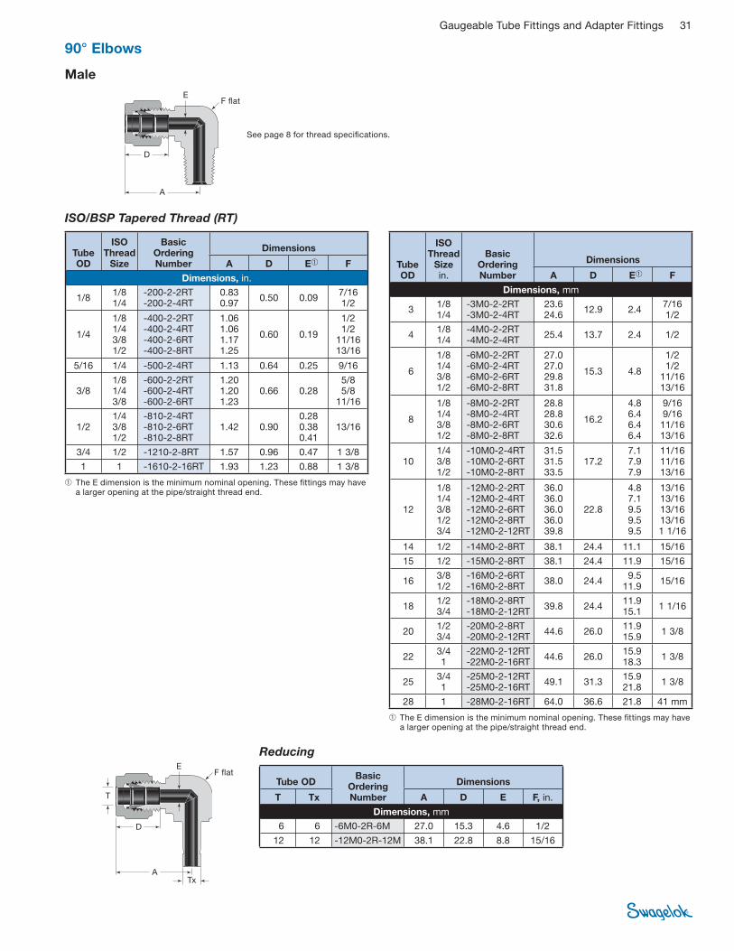
Gaugeable Tube Fittings and Adapter Fittings 31
See page 8 for thread specifi cations.
Male
ISO/BSP Tapered Thread (RT)
D
A
EF fl at
➀ The E dimension is the minimum nominal opening. These fi ttings may have a larger opening at the pipe/straight thread end.
➀ The E dimension is the minimum nominal opening. These fi ttings may have a larger opening at the pipe/straight thread end.
Reducing
Tube OD
ISO Thread
Size
Basic Ordering Number
Dimensions
A D E➀ F
Dimensions, in.
1/8 1/8 1/4
-200-2-2RT -200-2-4RT
0.83 0.97
0.50 0.09 7/16 1/2
1/4
1/8 1/4 3/8 1/2
-400-2-2RT -400-2-4RT -400-2-6RT -400-2-8RT
1.06 1.06 1.17 1.25
0.60 0.19
1/2 1/2
11/16 13/16
5/16 1/4 -500-2-4RT 1.13 0.64 0.25 9/16
3/8 1/8 1/4 3/8
-600-2-2RT -600-2-4RT -600-2-6RT
1.20 1.20 1.23
0.66 0.28 5/8 5/8
11/16
1/2 1/4 3/8 1/2
-810-2-4RT -810-2-6RT -810-2-8RT
1.42 0.90 0.28 0.38 0.41
13/16
3/4 1/2 -1210-2-8RT 1.57 0.96 0.47 1 3/8
1 1 -1610-2-16RT 1.93 1.23 0.88 1 3/8
Tube OD
ISO Thread
Size in.
Basic Ordering Number
Dimensions
A D E➀ F
Dimensions, mm
3 1/8 1/4
-3M0-2-2RT -3M0-2-4RT
23.6 24.6
12.9 2.4 7/16 1/2
4 1/8 1/4
-4M0-2-2RT -4M0-2-4RT
25.4 13.7 2.4 1/2
6
1/8 1/4 3/8 1/2
-6M0-2-2RT -6M0-2-4RT -6M0-2-6RT -6M0-2-8RT
27.0 27.0 29.8 31.8
15.3 4.8
1/2 1/2
11/16 13/16
8
1/8 1/4 3/8 1/2
-8M0-2-2RT -8M0-2-4RT -8M0-2-6RT -8M0-2-8RT
28.8 28.8 30.6 32.6
16.2
4.8 6.4 6.4 6.4
9/16 9/16 11/16 13/16
10 1/4 3/8 1/2
-10M0-2-4RT -10M0-2-6RT -10M0-2-8RT
31.5 31.5 33.5
17.2 7.1 7.9 7.9
11/16 11/16 13/16
12
1/8 1/4 3/8 1/2 3/4
-12M0-2-2RT -12M0-2-4RT -12M0-2-6RT -12M0-2-8RT -12M0-2-12RT
36.0 36.0 36.0 36.0 39.8
22.8
4.8 7.1 9.5 9.5 9.5
13/16 13/16 13/16 13/16 1 1/16
14 1/2 -14M0-2-8RT 38.1 24.4 11.1 15/16
15 1/2 -15M0-2-8RT 38.1 24.4 11.9 15/16
16 3/8 1/2
-16M0-2-6RT -16M0-2-8RT
38.0 24.4 9.5
11.9 15/16
18 1/2 3/4
-18M0-2-8RT -18M0-2-12RT
39.8 24.4 11.9 15.1
1 1/16
20 1/2 3/4
-20M0-2-8RT -20M0-2-12RT
44.6 26.0 11.9 15.9
1 3/8
22 3/4 1
-22M0-2-12RT -22M0-2-16RT
44.6 26.0 15.9 18.3
1 3/8
25 3/4 1
-25M0-2-12RT -25M0-2-16RT
49.1 31.3 15.9 21.8
1 3/8
28 1 -28M0-2-16RT 64.0 36.6 21.8 41 mm
Tube OD Basic
OrderingNumber
Dimensions
T Tx A D E F, in.
Dimensions, mm
6 6 -6M0-2R-6M 27.0 15.3 4.6 1/2
12 12 -12M0-2R-12M 38.1 22.8 8.8 15/16
90° Elbows
EF fl at
D
ATx
T
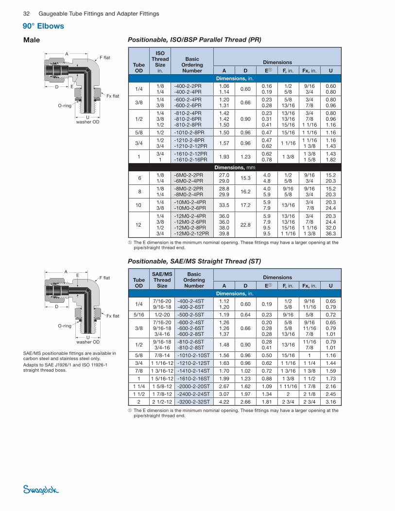
32 Gaugeable Tube Fittings and Adapter Fittings
Male Positionable, ISO/BSP Parallel Thread (PR)
O-ring
D
A
E
F fl at
Fx fl at
➀ The E dimension is the minimum nominal opening. These fi ttings may have a larger opening at the pipe/straight thread end.
Tube OD
ISO Thread
Size in.
Basic Ordering Number
Dimensions
A D E➀ F, in. Fx, in. U
Dimensions, in.
1/4 1/8 1/4
-400-2-2PR -400-2-4PR
1.06 1.14
0.60 0.16 0.19
1/2 5/8
9/16 3/4
0.60 0.80
3/8 1/4 3/8
-600-2-4PR -600-2-6PR
1.20 1.31
0.66 0.23 0.28
5/8 13/16
3/4 7/8
0.80 0.96
1/2 1/4 3/8 1/2
-810-2-4PR -810-2-6PR -810-2-8PR
1.42 1.42 1.50
0.90 0.23 0.31 0.41
13/16 13/16 15/16
3/4 7/8
1 1/16
0.80 0.96 1.16
5/8 1/2 -1010-2-8PR 1.50 0.96 0.47 15/16 1 1/16 1.16
3/4 1/2 3/4
-1210-2-8PR -1210-2-12PR
1.57 0.96 0.47 0.62
1 1/16 1 1/16 1 3/8
1.16 1.43
1 3/4 1
-1610-2-12PR -1610-2-16PR
1.93 1.23 0.62 0.78
1 3/8 1 3/8 1 5/8
1.43 1.82
Dimensions, mm
6 1/8 1/4
-6M0-2-2PR -6M0-2-4PR
27.0 29.0
15.3 4.0 4.8
1/2 5/8
9/16 3/4
15.2 20.3
8 1/8 1/4
-8M0-2-2PR -8M0-2-4PR
28.8 29.9
16.2 4.0 5.9
9/16 5/8
9/16 3/4
15.2 20.3
10 1/4 3/8
-10M0-2-4PR -10M0-2-6PR
33.5 17.2 5.9 7.9
13/16 3/4 7/8
20.3 24.4
12
1/4 3/8 1/2 3/4
-12M0-2-4PR -12M0-2-6PR -12M0-2-8PR -12M0-2-12PR
36.0 36.0 38.0 39.8
22.8
5.9 7.9 9.5 9.5
13/16 13/16 15/16 1 1/16
3/4 7/8
1 1/16 1 3/8
20.3 24.4 32.0 36.3
Positionable, SAE/MS Straight Thread (ST)
O-ring
Uwasher OD
SAE/MS positionable fittings are available in carbon steel and stainless steel only.
Adapts to SAE J1926/1 and ISO 11926-1 straight thread boss.
D
AE
F fl at
Fx fl at
➀ The E dimension is the minimum nominal opening. These fi ttings may have a larger opening at the pipe/straight thread end.
Tube OD
SAE/MS Thread
Size
Basic Ordering Number
Dimensions
A D E➀ F, in. Fx, in. U
Dimensions, in.
1/4 7/16-20 9/16-18
-400-2-4ST -400-2-6ST
1.12 1.20
0.60 0.19 1/2 5/8
9/16 11/16
0.65 0.79
5/16 1/2-20 -500-2-5ST 1.19 0.64 0.23 9/16 5/8 0.72
3/8 7/16-20 9/16-18 3/4-16
-600-2-4ST -600-2-6ST -600-2-8ST
1.26 1.26 1.37
0.66 0.20 0.28 0.28
5/8 5/8
13/16
9/16 11/16 7/8
0.65 0.79 1.01
1/2 9/16-18 3/4-16
-810-2-6ST -810-2-8ST
1.48 0.90 0.28 0.41
13/16 11/16 7/8
0.79 1.01
5/8 7/8-14 -1010-2-10ST 1.56 0.96 0.50 15/16 1 1.16
3/4 1 1/16-12 -1210-2-12ST 1.63 0.96 0.62 1 1/16 1 1/4 1.44
7/8 1 3/16-12 -1410-2-14ST 1.70 1.02 0.72 1 3/16 1 3/8 1.59
1 1 5/16-12 -1610-2-16ST 1.99 1.23 0.88 1 3/8 1 1/2 1.73
1 1/4 1 5/8-12 -2000-2-20ST 2.67 1.62 1.09 1 11/16 1 7/8 2.16
1 1/2 1 7/8-12 -2400-2-24ST 3.07 1.97 1.34 2 2 1/8 2.45
2 2 1/2-12 -3200-2-32ST 4.22 2.66 1.81 2 3/4 2 3/4 3.16
Uwasher OD
90° Elbows
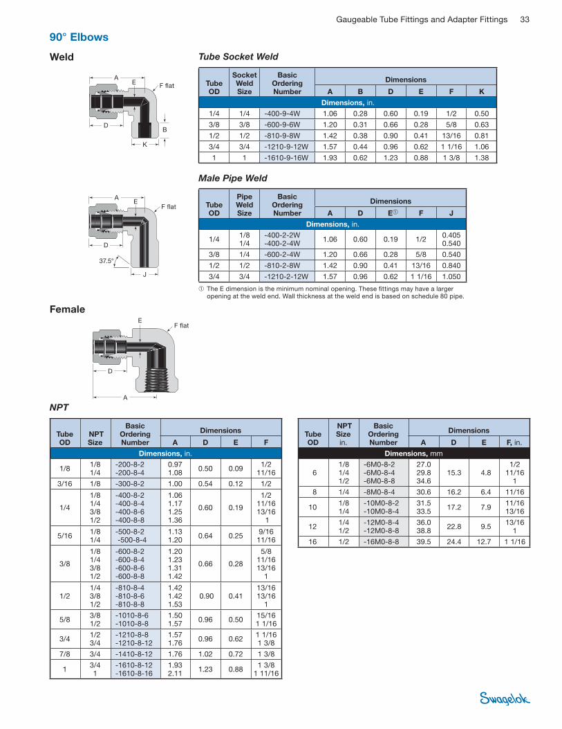
Gaugeable Tube Fittings and Adapter Fittings 33
NPT
Female
D
A
EF fl at
Male Pipe Weld
D
J
AE
F fl at
37.5°
➀ The E dimension is the minimum nominal opening. These fi ttings may have a larger opening at the weld end. Wall thickness at the weld end is based on schedule 80 pipe.
Weld Tube Socket Weld
DB
A
K
EF fl at Tube
OD
Socket WeldSize
Basic OrderingNumber
Dimensions
A B D E F K
Dimensions, in.
1/4 1/4 -400-9-4W 1.06 0.28 0.60 0.19 1/2 0.50
3/8 3/8 -600-9-6W 1.20 0.31 0.66 0.28 5/8 0.63
1/2 1/2 -810-9-8W 1.42 0.38 0.90 0.41 13/16 0.81
3/4 3/4 -1210-9-12W 1.57 0.44 0.96 0.62 1 1/16 1.06
1 1 -1610-9-16W 1.93 0.62 1.23 0.88 1 3/8 1.38
Tube OD
Pipe Weld Size
Basic Ordering Number
Dimensions
A D E➀ F J
Dimensions, in.
1/4 1/8 1/4
-400-2-2W -400-2-4W
1.06 0.60 0.19 1/2 0.405 0.540
3/8 1/4 -600-2-4W 1.20 0.66 0.28 5/8 0.540
1/2 1/2 -810-2-8W 1.42 0.90 0.41 13/16 0.840
3/4 3/4 -1210-2-12W 1.57 0.96 0.62 1 1/16 1.050
Tube OD
NPT Size
Basic OrderingNumber
Dimensions
A D E F
Dimensions, in.
1/8 1/8 1/4
-200-8-2 -200-8-4
0.971.08
0.50 0.09 1/2
11/16
3/16 1/8 -300-8-2 1.00 0.54 0.12 1/2
1/4
1/8 1/4 3/8 1/2
-400-8-2 -400-8-4 -400-8-6 -400-8-8
1.06 1.17 1.25 1.36
0.60 0.19
1/2 11/16 13/16
1
5/16 1/8 1/4
-500-8-2 -500-8-4
1.13 1.20
0.64 0.25 9/16 11/16
3/8
1/8 1/4 3/8 1/2
-600-8-2 -600-8-4 -600-8-6 -600-8-8
1.20 1.23 1.31 1.42
0.66 0.28
5/8 11/16 13/16
1
1/2 1/4 3/8 1/2
-810-8-4 -810-8-6 -810-8-8
1.42 1.42 1.53
0.90 0.41 13/1613/16
1
5/8 3/8 1/2
-1010-8-6 -1010-8-8
1.50 1.57
0.96 0.50 15/16 1 1/16
3/4 1/2 3/4
-1210-8-8 -1210-8-12
1.57 1.76
0.96 0.62 1 1/16 1 3/8
7/8 3/4 -1410-8-12 1.76 1.02 0.72 1 3/8
1 3/4 1
-1610-8-12 -1610-8-16
1.93 2.11
1.23 0.88 1 3/8
1 11/16
Tube OD
NPT Size in.
Basic OrderingNumber
Dimensions
A D E F, in.
Dimensions, mm
6 1/8 1/4 1/2
-6M0-8-2 -6M0-8-4 -6M0-8-8
27.0 29.8 34.6
15.3 4.8 1/2
11/16 1
8 1/4 -8M0-8-4 30.6 16.2 6.4 11/16
10 1/8 1/4
-10M0-8-2 -10M0-8-4
31.5 33.5
17.2 7.9 11/16 13/16
12 1/4 1/2
-12M0-8-4 -12M0-8-8
36.0 38.8
22.8 9.5 13/16
1
16 1/2 -16M0-8-8 39.5 24.4 12.7 1 1/16
90° Elbows

34 Gaugeable Tube Fittings and Adapter Fittings
Positionable, SAE/MS Straight Thread (ST)
45° Elbows
Male NPT
➀ The E dimension is the minimum nominal opening. These fi ttings may have a larger opening at the pipe/straight thread end.
D
A
E
F fl at
D
A
E
F fl at
O-ring
➀ The E dimension is the minimum nominal opening. These fi ttings may have a larger opening at the pipe/straight thread end.
Tube OD
NPT Size
Basic OrderingNumber
Dimensions
A D E➀ F
Dimensions, in.
1/4 1/8 1/4
-400-5-2 -400-5-4
0.97 0.60 0.19 1/2
3/8 1/8 1/4 3/8
-600-5-2 -600-5-4 -600-5-6
1.10 1.10 1.15
0.66 0.19 0.28 0.28
5/8 5/8
13/16
1/2 3/8 1/2
-810-5-6 -810-5-8
1.26 0.90 0.38 0.41
13/16
3/4 3/4 -1210-5-12 1.33 0.96 0.62 1 1/16
1 1 -1610-5-16 1.59 1.23 0.88 1 3/8
Tube OD
SAE/MS Thread
Size
Basic OrderingNumber
Dimensions
A D E➀ F U
Dimensions, in.
1/4 7/16-20 -400-5-4ST 1.01 0.60 0.19 1/2 0.65
3/8 9/16-18 -600-5-6ST 1.10 0.66 0.28 5/8 0.79
1/2 3/4-16 -810-5-8ST 1.26 0.90 0.41 13/16 1.01
3/4 1 1/16-12 -1210-5-12ST 1.33 0.96 0.62 1 1/16 1.44
1 1 5/16-12 -1610-5-16ST 1.59 1.23 0.88 1 3/8 1.73
SAE/MS positionable fittings are available in carbon steel and stainless steel only.
Adapts to SAE J1926/1 and ISO 11926-1 straight thread boss.
U
was
her O
D

Gaugeable Tube Fittings and Adapter Fittings 35
Reducing Union (Fractional)
Tees
Unions
Union
D
AAx
Ax
E
F fl at
D
Dx
A
Tx
T
Ax E F fl at
Tube OD
Basic Ordering Number
Dimensions
A Ax D E F
Dimensions, in.
1/16 -100-3 1.40 0.70 0.34 0.05 3/8
1/8 -200-3 1.76 0.88 0.50 0.09 3/8
3/16 -300-3 1.92 0.96 0.54 0.12 7/16
1/4 -400-3 2.12 1.06 0.60 0.19 1/2
5/16 -500-3 2.34 1.17 0.64 0.25 5/8
3/8 -600-3 2.40 1.20 0.66 0.28 5/8
1/2 -810-3 2.84 1.42 0.90 0.41 13/16
5/8 -1010-3 3.06 1.53 0.96 0.50 1
3/4 -1210-3 3.14 1.57 0.96 0.62 1 1/16
7/8 -1410-3 3.52 1.76 1.02 0.72 1 3/8
1 -1610-3 3.86 1.93 1.23 0.88 1 3/8
1 1/8 -1810-3 4.34 2.17 1.23 0.97 1 11/16
1 1/4 -2000-3 5.34 2.67 1.62 1.09 1 11/16
1 1/2 -2400-3 6.20 3.10 1.97 1.34 2
2 -3200-3 8.44 4.22 2.66 1.81 2 3/4
Tube OD
Basic Ordering Number
Dimensions
A Ax D E F, in.
Dimensions, mm
2 -2M0-3 44.7 22.3 12.9 1.7 3/8
3 -3M0-3 44.7 22.3 12.9 2.4 3/8
4 -4M0-3 50.8 25.4 13.7 2.4 1/2
6 -6M0-3 53.9 27.0 15.3 4.8 1/2
8 -8M0-3 59.7 29.9 16.2 6.4 5/8
10 -10M0-3 63.0 31.5 17.2 7.9 11/16
12 -12M0-3 72.0 36.0 22.8 9.5 13/16
14 -14M0-3 77.6 38.8 24.4 11.1 1
15 -15M0-3 77.6 38.8 24.4 11.9 1
16 -16M0-3 77.6 38.8 24.4 12.7 1
18 -18M0-3 79.6 39.8 24.4 15.1 1 1/16
20 -20M0-3 89.3 44.6 26.0 15.9 1 3/8
22 -22M0-3 89.3 44.6 26.0 18.3 1 3/8
25 -25M0-3 98.3 49.1 31.3 21.8 1 3/8
28 -28M0-3 128 64.0 36.6 21.8 41 mm
30 -30M0-3 140 69.9 39.6 26.2 46 mm
32 -32M0-3 145 72.3 42.0 28.6 46 mm
38 -38M0-3 168 84.0 49.4 33.7 55 mm
50 -50M0-3 211 106 65.0 45.2 2 3/4
Tube OD Basic
Ordering Number
Dimensions
T Tx A Ax D Dx E F
Dimensions, in.
3/8 1/4 -600-3-6-4 2.40 1.14 0.66 0.60 0.19 5/8
1/2 1/4 3/8
-810-3-8-4 -810-3-8-6
2.84 1.25 1.31
0.90 0.60 0.66
0.19 0.28
13/16
5/8 3/8 -1010-3-10-6 3.06 1.42 0.96 0.66 0.28 1
3/4 3/8 1/2
-1210-3-12-6 -1210-3-12-8
3.14 1.46 1.57
0.96 0.66 0.90
0.28 0.41
1 1/16
1 3/8 1/2 3/4
-1610-3-16-6 -1610-3-16-8 -1610-3-16-12
3.86 1.65 1.76 1.76
1.23 0.66 0.90 0.96
0.28 0.41 0.62
1 3/8
1 1/4 1 -2000-3-20-16 5.34 2.17 1.62 1.23 0.88 1 11/16
1 1/2 1 -2400-3-24-16 6.20 2.36 1.97 1.23 0.88 2
2 1 -3200-3-32-16 8.44 2.79 2.66 1.23 0.88 2 3/4

36 Gaugeable Tube Fittings and Adapter Fittings
Reducing Union (Metric)
D
Dx
ATx
T
Ax E F fl at
Tube OD Basic
Ordering Number
Dimensions
T Tx A Ax D Dx E F, in.
Dimensions, mm
3
6
-3M0-3-3M-6M 49.3 26.9 12.9 15.3 2.4 1/2
8 -8M0-3-8M-6M 59.9 29.0 16.2 15.3 4.8 5/8
10 -10M0-3-10M-6M 63.0 29.7 17.2 15.3 4.8 11/16
12 -12M0-3-12M-6M 72.0 31.8 22.8 15.3 4.8 13/16
15
12
-15M0-3-15M-12M 77.7 38.9 24.4 22.8 9.5 1
16 -16M0-3-16M-12M 77.6 38.9 24.4 22.8 9.5 1
18 -18M0-3-18M-12M 79.8 39.9 24.4 22.8 9.5 1 1/16
22 -22M0-3-22M-12M 89.4 44.7 26.0 22.8 9.5 1 3/8
25 -25M0-3-25M-12M 98.0 44.7 31.3 22.8 9.5 1 3/8
Reducing Union
D Dx
AAx Ay
Ax
E F fl at
TxT
T
Tube OD Basic
Ordering Number
Dimensions
T Tx A Ax Ay D Dx E F
Dimensions, in.
3/8 1/4 -600-3-4-6 2.34 1.20 1.14 0.66 0.60 0.19 5/8
DDx
AAx Ay
Ay
E F fl at
TxT
Tx
Tube OD Basic
Ordering Number
Dimensions
T Tx A Ax Ay D Dx E F
Dimensions, in.
1/2
3/8
-810-3-6-6 2.73 1.42 1.31 0.90 0.66 0.28 13/16
5/8 -1010-3-6-6 2.95 1.53 1.42 0.96 0.66 0.28 1
3/4 -1210-3-6-6 3.03 1.57 1.46 0.96 0.66 0.28 1 1/16
D
Dx
Dx1
AAx Ay
Ay1E
F fl at
TxT
Tx1
Tube OD Basic
Ordering Number
Dimensions
T Tx Tx1 A Ax Ay Ay1 D Dx Dx1 E F
Dimensions, in.
5/8 1/2
3/8
-1010-3-8-6 3.06 1.53 1.53 1.42 0.96 0.90
0.66 0.28
1
3/4 1/2 -1210-3-8-6 3.14 1.57 1.57 1.46 0.96 0.90 1 1/16
1 3/4 -1610-3-12-6 3.69 1.93 1.76 1.65 1.23 0.96 1 3/8
Unions
Tees

Gaugeable Tube Fittings and Adapter Fittings 37
Male Branch, NPT (TTM)
D
A
H
E
➀ The E dimension is the minimum nominal opening. These fi ttings may have a larger opening at the pipe/straight thread end.
Tube OD
NPT Size in.
Basic Ordering Number
Dimensions
A D E➀ F, in. H
Dimensions, in.
1/8 1/8 1/4
-200-3TTM -200-3-4TTM
1.86 1.94
0.50 0.09 7/16 1/2
0.70 0.92
3/16 1/8 -300-3TTM 1.92 0.54 0.12 7/16 0.70
1/4 1/8 1/4
-400-3TTM -400-3-4TTM
2.12 0.60 0.19 1/2 0.74 0.92
5/16 1/8 -500-3TTM 2.34 0.64 0.19 5/8 0.82
3/8 1/4 3/8
-600-3TTM -600-3-6TTM
2.40 2.62
0.66 0.28 5/8
13/16 1.00 1.11
1/2 3/8 1/2
-810-3TTM -810-3-8TTM
2.84 0.90 0.38 0.41
13/16 1.11 1.30
5/8 1/2 -1010-3TTM 3.06 0.96 0.47 1 1.41
3/4 3/4 -1210-3TTM 3.14 0.96 0.62 1 1/16 1.45
Dimensions, mm
6 1/8 1/4
-6M0-3TTM -6M0-3-4TTM
53.9 15.3 4.8 1/2 18.8 23.4
8 1/8 1/4
-8M0-3TTM-8M0-3-4TTM
59.7 16.2 4.8 6.4
5/8 20.8 25.4
10 1/4 -10M0-3TTM 67.0 17.2 7.1 13/16 26.2
12 3/8 1/4 1/2
-12M0-3TTM -12M0-3-4TTM -12M0-3-8TTM
72.0 22.8 9.5 7.1 9.5
13/16 28.2 28.2 33.0
16 1/2 -16M0-3TTM 77.6 24.4 11.9 1 35.8
Run, NPT (TMT)
➀ The E dimension is the minimum nominal opening. These fi ttings may have a larger opening at the pipe/straight thread end.
D
AAx
E
F fl atAx
Tube OD
NPT Size in.
Basic Ordering Number
Dimensions
A Ax D E➀ F, in.
Dimensions, in.
1/8 1/8 1/4
-200-3TMT -200-3-4TMT
1.63 1.89
0.93 0.97
0.50 0.09 7/16 1/2
3/16 1/8 -300-3TMT 1.66 0.96 0.54 0.12 7/16
1/4 1/8 1/4
-400-3TMT -400-3-4TMT
1.80 1.98
1.06 0.60 0.19 1/2
5/16 1/8 -500-3TMT 1.99 1.17 0.64 0.19 5/8
3/8 1/4 3/8
-600-3TMT -600-3-6TMT
2.20 2.42
1.20 1.31
0.66 0.28 5/8
13/16
1/2 3/8 1/2
-810-3TMT -810-3-8TMT
2.53 2.72
1.42 0.90 0.38 0.41
13/16
5/8 1/2 -1010-3TMT 2.88 1.50 0.96 0.47 15/16
3/4 3/4 -1210-3TMT 3.02 1.57 0.96 0.62 1 1/16
Dimensions, mm
6 1/8 1/4
-6M0-3TMT -6M0-3-4TMT
45.8 50.3
27.0 15.3 4.8 1/2
8 1/4 -8M0-3-4TMT 55.3 29.9 16.2 6.4 5/8
12 1/4 1/2
-12M0-3-4TMT -12M0-3-8TMT
64.2 69.0
36.0 22.8 7.1 9.5
13/16
16 1/2 -16M0-3TMT 73.1 38.0 24.4 11.9 15/16
Tees
F fl at

38 Gaugeable Tube Fittings and Adapter Fittings
U washer
OD
D
AAx
Ax
E F fl at Fx fl at
O-ring
Positionable Branch, ISO/BSP Parallel Thread (TTR)
Tube ports are identical.
See page 8 for thread specifi cations.
➀ The E dimension is the minimum nominal opening. These fi ttings may have a larger opening at the pipe/straight thread end.
Tube OD
ISO Thread
Size in.
Basic Ordering Number
Dimensions
A Ax D E➀ F, in. Fx, in. H U
Dimensions, in.
1/4 1/8 1/4
-400-3TTR -400-3-4TTR
2.12 2.28
1.06 1.14
0.60 0.16 0.19
1/2 5/8
9/16 3/4
1.04 1.27
0.60 0.80
3/8 1/4 -600-3TTR 2.40 1.20 0.66 0.23 5/8 3/4 1.27 0.80
1/2 3/8 1/2
-810-3TTR -810-3-8TTR
2.84 3.00
1.42 1.50
0.90 0.31 0.41
13/16 15/16
7/8 1 1/16
1.46 1.71
0.96 1.16
5/8 1/2 -1010-3TTR 3.00 1.50 0.96 0.47 15/16 1 1/16 1.71 1.16
3/4 3/4 1/2
-1210-3TTR -1210-3-8TTR
3.14 1.57 0.96 0.62 0.47
1 1/16 1 3/8 1 1/16
1.92 1.78
1.43 1.16
1 1 -1610-3TTR 3.86 1.93 1.23 0.78 1 3/8 1 5/8 2.11 1.92
Dimensions, mm
6 1/8 1/4
-6M0-3TTR -6M0-3-4TTR
53.9 58.0
27.0 29.0
15.3 4.0 4.8
1/2 5/8
9/16 3/4
26.4 32.2
15.2 20.3
8 1/8 1/4
-8M0-3TTR -8M0-3-4TTR
57.7 59.7
30.0 16.2 4.0 5.9
9/16 5/8
9/16 3/4
28.4 32.3
15.2 20.3
10 1/4 -10M0-3TTR 67.0 33.5 17.2 5.9 13/16 3/4 35.1 20.3
12 3/8 1/2
-12M0-3TTR -12M0-3-8TTR
72.0 76.1
36.1 38.1
22.8 7.9 9.5
13/16 5/16
7/8 1 1/16
37.1 43.4
24.4 29.5
Male Positionable Branch, SAE/MS Straight Thread (TTS)
➀ The E dimension is the minimum nominal opening. These fi ttings may have a larger opening at the pipe/straight thread end.
Tube OD
SAE/MS Thread
Size
Basic OrderingNumber
Dimensions
A Ax D E➀ F Fx H U
Dimensions, in.
1/4 7/16-20 -400-3TTS 2.24 1.12 0.60 0.19 1/2 9/16 1.12 0.65
3/8 9/16-18 -600-3TTS 2.52 1.26 0.66 0.28 5/8 11/16 1.27 0.79
1/2 3/4-16 -810-3TTS 2.96 1.48 0.90 0.41 13/16 7/8 1.49 1.01
3/4 1 1/16-12 -1210-3TTS 3.26 1.63 0.96 0.62 1 1/16 11/4 1.92 1.44
1 1 5/16-12 -1610-3TTS 3.98 1.99 1.23 0.88 1 3/8 1 1/2 2.11 1.73
1 1/4 1 5/8-12 -2000-3TTS 5.34 2.67 1.62 1.09 1 11/16 1 7/8 2.29 2.16
1 1/2 1 7/8-12 -2400-3TTS 6.14 3.07 1.97 1.34 2 2 1/8 2.45 2.45
2 2 1/2-12 -3200-3TTS 8.44 4.22 2.66 1.81 2 3/4 2 3/4 2.77 3.16 SAE/MS positionable fittings are available in carbon steel and stainless steel only.
Adapts to SAE J1926/1 and ISO 11926-1 straight thread boss.
Positionable Run, SAE/MS Straight Thread (TST)
➀ The E dimension is the minimum nominal opening. These fi ttings may have a larger opening at the pipe/straight thread end.
Tube OD
SAE/MS Thread
Size
Basic Ordering Number
Dimensions
A Ax D E➀ F Fx U
Dimensions, in.
1/4 7/16-20 -400-3TST 2.24 1.12 0.60 0.19 1/2 9/16 0.65
3/8 9/16-18 -600-3TST 2.53 1.26 0.66 0.28 5/8 11/16 0.79
1/2 3/4-16 -810-3TST 2.97 1.48 0.90 0.41 13/16 7/8 1.01
3/4 1 1/16-12 -1210-3TST 3.55 1.63 0.96 0.62 1 1/16 1 1/4 1.44
1 1 5/16-12 -1610-3TST 4.10 1.99 1.23 0.88 1 3/8 1 1/2 1.73
1 1/4 1 5/8-12 -2000-3TST 4.96 2.67 1.62 1.09 1 11/16 1 7/8 2.16
1 1/2 1 7/8-12 -2400-3TST 5.45 3.07 1.97 1.34 2 2 1/8 2.45
2 2 1/2-12 -3200-3TST 7.04 4.22 2.66 1.81 2 3/4 2 3/4 3.16 SAE/MS positionable fittings are available in carbon steel and stainless steel only.
Adapts to SAE J1926/1 and ISO 11926-1 straight thread boss.
Tees
D
AAx
H
E F fl at
Fx fl at
O-ring
Uwasher OD
D
AAx
H
E F fl at
Fx fl at
O-ring
Uwasher OD

Gaugeable Tube Fittings and Adapter Fittings 39
Positionable Run, ISO/BSP Parallel Thread (TRT)
See page 8 for thread specifi cations.
Male
➀ The E dimension is the minimum nominal opening. These fi ttings may have a larger opening at the pipe/straight thread end.
Tube OD
ISO Thread
Size in.
Basic Ordering Number
Dimensions
A Ax D E➀ F, in. Fx, in. U
Dimensions, in.
1/4 1/8 1/4
-400-3TRT -400-3-4TRT
2.10 2.41
1.06 1.14
0.60 0.16 0.19
1/2 5/8
9/16 3/4
0.60 0.80
3/8 1/4 -600-3TRT 2.47 1.20 0.66 0.23 5/8 3/4 0.80
1/2 3/8 1/2
-810-3TRT -810-3-8TRT
2.88 3.21
1.42 1.50
0.90 0.31 0.41
13/16 15/16
7/8 1 1/16
0.96 1.16
5/8 1/2 -1010-3TRT 3.21 1.50 0.96 0.47 15/16 1 1/16 1.16
3/4 3/4 1/2
-1210-3TRT -1210-3-8TRT
3.49 3.35
1.57 0.96 0.62 0.47
1 1/16 1 3/8 1 1/16
1.43 1.16
1 1 -1610-3TRT 4.04 1.93 1.23 0.78 1 3/8 1 5/8 1.82
Dimensions, mm
6 1/8 1/4
-6M0-3TRT -6M0-3-4TRT
53.4 61.2
27.0 29.0
15.3 4.0 4.8
1/2 5/8
9/16 3/4
15.2 20.3
8 1/8 1/4
-8M0-3TRT -8M0-3-4TRT
56.3 62.1
28.8 29.9
16.2 4.0 6.4
9/16 5/8
9/16 3/4
15.2 20.3
10 1/4 -10M0-3TRT 68.6 33.5 17.2 5.9 13/16 3/4 20.3
12 3/8 1/2
-12M0-3TRT -12M0-3-8TRT
73.1 81.5
36.0 38.0
22.8 7.9 9.5
13/16 15/16
7/8 1 1/16
24.4 29.5
Tube ports are identical.
Female Run, NPT (TFT)
D
AAx
AxE
F fl atTube OD
NPT Sizein.
Basic OrderingNumber
Dimensions
A Ax D E F, in.
Dimensions, in.
1/8 1/8 -200-3TFT 1.72 0.97 0.50 0.09 1/2
1/4 1/8 1/4
-400-3TFT -400-3-4TFT
1.81 2.05
1.06 1.17
0.60 0.19 1/2
11/16
3/8 1/4 -600-3TFT 2.11 1.23 0.66 0.28 11/16
1/2 3/8 1/2
-810-3TFT -810-3-8TFT
2.30 2.69
1.42 1.57
0.90 0.41 13/16 1 1/16
3/4 3/4 -1210-3TFT 3.01 1.76 0.96 0.62 1 3/8
1 3/4 1
-1610-3-12TFT -1610-3TFT
3.18 3.61
1.93 2.11
1.23 0.88 1 3/8
1 11/16
Dimensions, mm
6 1/8 1/4
-6M0-3TFT -6M0-3-4TFT
46.0 52.1
27.0 29.8
15.3 4.8 1/2
11/16
8 1/8 1/4
-8M0-3TFT -8M0-3-4TFT
48.9 53.0
29.9 30.6
16.2 6.4 5/8
11/16
10 1/4 -10M0-3TFT 55.9 33.5 17.2 7.9 13/16
12 1/4 3/8 1/2
-12M0-3-4TFT -12M0-3TFT -12M0-3-8TFT
58.4 58.4 68.3
36.0 36.0 39.8
22.8 9.5
10.3 9.5
13/16 13/16 1 1/16
16 1/2 -16M0-3TFT 68.2 39.8 24.4 12.7 1 1/16
U washer
OD
D
AAx
Ax
E F fl at Fx fl at
O-ring
Tees

40 Gaugeable Tube Fittings and Adapter Fittings
Union
Branch, NPT (TTF)
D
A
H
E
F fl at
Tube OD
NPT Size in.
Basic Ordering Number
Dimensions
A D E F, in. H
Dimensions, in.
1/8 1/8 -200-3TTF 1.94 0.50 0.09 1/2 0.75
1/4 1/8 1/4
-400-3TTF -400-3-4TTF
2.12 2.34
0.60 0.19 1/2
11/16 0.75 0.88
3/8 1/4 3/8 1/2
-600-3TTF -600-3-6TTF -600-3-8TTF
2.46 2.62 2.84
0.66 0.28 11/16 13/16
1
0.88 0.88 1.12
1/2 1/4 3/8 1/2
-810-3-4TTF -810-3TTF -810-3-8TTF
2.84 2.84 3.06
0.90 0.41 13/16 13/16
1
0.88 0.88 1.12
5/8 1/2 -1010-3TTF 3.06 0.96 0.50 1 1.12
3/4 3/4 -1210-3TTF 3.52 0.96 0.62 1 3/8 1.25
1 3/4 1
-1610-3-12TTF -1610-3TTF
3.86 4.22
1.23 0.88 1 3/8
1 11/16 1.25 1.50
Dimensions, mm
6 1/8 1/4
-6M0-3TTF -6M0-3-4TTF
53.9 59.5
15.3 4.8 1/2
11/16 19.0 22.4
8 1/8 1/4
-8M0-3TTF -8M0-3-4TTF
59.7 61.2
16.2 6.4 5/8
11/16 19.0 22.4
10 1/4 -10M0-3TTF 67.0 17.2 7.9 13/16 22.4
12 1/4 3/8 1/2
-12M0-3-4TTF -12M0-3TTF -12M0-3-8TTF
72.0 72.0 77.7
22.8 9.5 13/16 13/16
1
22.4 22.4 28.4
16 1/2 -16M0-3TTF 77.6 24.4 12.7 1 28.4
Cross
D
A
A
E
F fl at
Tube OD
Basic Ordering Number
Dimensions
A D E F, in.
Dimensions, in.
1/8 -200-4 1.76 0.50 0.09 3/8
1/4 -400-4 2.12 0.60 0.19 1/2
5/16 -500-4 2.34 0.64 0.25 5/8
3/8 -600-4 2.40 0.66 0.28 5/8
1/2 -810-4 2.84 0.90 0.41 13/16
3/4 -1210-4 3.14 0.96 0.62 1 1/16
1 -1610-4 3.86 1.23 0.88 1 3/8
Dimensions, mm
3 -3M0-4 44.7 12.9 2.4 3/8
6 -6M0-4 53.9 15.3 4.8 1/2
8 -8M0-4 59.7 16.2 6.4 5/8
10 -10M0-4 67.0 17.2 7.9 13/16
12 -12M0-4 72.0 22.8 9.5 13/16
16 -16M0-4 74.0 24.4 12.7 15/16
18 -18M0-4 76.6 24.4 15.1 1 1/16
20 -20M0-4 89.3 26.0 15.9 1 3/8
22 -22M0-4 89.4 26.0 18.3 5/8
25 -25M0-4 98.3 31.3 21.8 1 3/8
Female
Tees
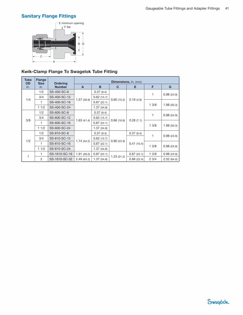
Gaugeable Tube Fittings and Adapter Fittings 41
Sanitary Flange Fittings
A
G
F fl at
B
C
E minimum opening
Tube OD in.
Flange Size in.
Ordering Number
Dimensions, in. (mm)
A B C E F G
1/4
1/2 SS-400-SC-8
1.57 (39.9)
0.37 (9.4)
0.60 (15.2) 0.19 (4.8)
1 0.98 (24.9) 3/4 SS-400-SC-12 0.62 (15.7)
1 SS-400-SC-16 0.87 (22.1) 1 3/8 1.98 (50.3)
1 1/2 SS-400-SC-24 1.37 (34.8)
3/8
1/2 SS-600-SC-8
1.63 (41.4)
0.37 (9.4)
0.66 (16.8) 0.28 (7.1)
1 0.98 (24.9) 3/4 SS-600-SC-12 0.62 (15.7)
1 SS-600-SC-16 0.87 (22.1) 1 3/8 1.98 (50.3)
1 1/2 SS-600-SC-24 1.37 (34.8)
1/2
1/2 SS-810-SC-8
1.74 (44.2)
0.37 (9.4)
0.90 (22.9)
0.37 (9.4) 1 0.98 (24.9)
3/4 SS-810-SC-12 0.62 (15.7)
0.41 (10.4) 1 SS-810-SC-16 0.87 (22.1) 1 3/8 0.98 (24.9)
1 1/2 SS-810-SC-24 1.37 (34.8)
1 1 SS-1610-SC-16 1.91 (48.5) 0.87 (22.1)
1.23 (31.2) 0.87 (22.1) 1 3/8 0.98 (24.9)
2 SS-1610-SC-32 2.49 (63.2) 1.37 (34.8) 0.88 (22.4) 2 3/4 2.52 (64.0)
Kwik-Clamp Flange To Swagelok Tube Fitting

42 Gaugeable Tube Fittings and Adapter Fittings
Solve Alignment Problems and Reduce Inventories
Swagelok tube adapters can help eliminate diffi cult alignment problems and
reduce inventories. Swagelok tube adapters can be used with any Swagelok tube
fi ttings in this catalog. So, stocking union elbows and union tees in various sizes
and materials—along with commonly used Swagelok adapters—eliminates the
need for stocking special elbows and tees.
Typical Alignment Problem
When installing pipe elbows or tees, it is often diffi cult to align the fi tting with the
desired run.
� Swagelok tube adapters are to be used ONLY in Swagelok tube fi ttings.
Use in fi ttings made by other manufacturers may result in leakage or
slippage.
Tube Adapters
1. In this example, the
installation requires
connecting tubing to a
female end connection.
2. When the pipe connection
is tightened, the male elbow
points in the wrong direction
for the desired run. Loosening
the pipe connection could
mean leakage at the pipe
thread.
3. Tighten the pipe
connection of a
Swagelok male adapter
into the female end
connection.
4. Connect a Swagelok union
elbow or tee to the adapter by
tightening the Swagelok tube
fi tting with a wrench, while
holding the elbow or tee in the
desired direction. Insert the
tubing into the other end of the
Swagelok elbow or tee and
install the fi tting.
Swagelok Solution
By using a Swagelok tube adapter in conjunction with a union elbow or tee, these
diffi culties can be avoided.
100
2000
1505
0
10
14
50

Gaugeable Tube Fittings and Adapter Fittings 43
➀ The E dimension is the minimum nominal opening. These fi ttings may have a larger opening at the pipe/straight thread end.
➁ Furnished with nut and preswaged ferrules.
➀ The E dimension is the minimum nominal opening. These fi ttings may have a larger opening at the pipe/straight thread end.
➁ Furnished with nut and preswaged ferrules.
Male
NPT
1 in./25 mm and under
A
E
F fl at
Over 1 in./25 mm
A
E
F fl at
ISO/BSP Tapered Thread (RT)
Tube OD
NPT Size in.
Basic OrderingNumber
Dimensions
A E➀ F
Dimensions, in.
1/8 1/8 1/4
-2-TA-1-2 -2-TA-1-4
1.16 1.37
0.08 7/16 9/16
3/16 1/8 1/4
-3-TA-1-2 -3-TA-1-4
1.19 1.40
0.12 7/16 9/16
1/4
1/8 1/4 3/8 1/2
-4-TA-1-2 -4-TA-1-4 -4-TA-1-6 -4-TA-1-8
1.25 1.46 1.49 1.71
0.17
7/16 9/16 11/16 7/8
5/16 1/8 1/4
-5-TA-1-2 -5-TA-1-4
1.29 1.50
0.19 0.22
7/16 9/16
3/8
1/8 1/4 3/8 1/2
-6-TA-1-2 -6-TA-1-4 -6-TA-1-6 -6-TA-1-8
1.32 1.53 1.56 1.78
0.19 0.27 0.27 0.27
7/16 9/16 11/16 7/8
1/2 1/4 3/8 1/2
-8-TA-1-4 -8-TA-1-6 -8-TA-1-8
1.75 1.78 2.00
0.28 0.37 0.37
9/16 11/16 7/8
5/8 1/2 -10-TA-1-8 2.06 0.47 7/8
3/4 1/2 3/4
-12-TA-1-8 -12-TA-1-12
2.06 0.47 0.58
7/8 1 1/16
1 3/4 1
-16-TA-1-12 -16-TA-1-16
2.31 2.60
0.62 0.80
1 1/16 1 3/8
1 1/4 1 1/4 -20-TA-1-20➁ 3.16 1.02 1 3/4
1 1/2 1 1/2 -24-TA-1-24➁ 3.72 1.25 2 1/8
2 2 -32-TA-1-32➁ 4.70 1.72 2 3/4
Dimensions, mm
6 1/8 1/4
-6-MTA-1-2 -6-MTA-1-4
32.8 38.1
4.1 12 14
8 1/4 3/8
-8-MTA-1-4 -8-MTA-1-6
39.1 39.9
5.6 14 19
10 1/4 3/8 1/2
-10-MTA-1-4 -10-MTA-1-6 -10-MTA-1-8
39.9 40.6 46.2
7.1 14 18 22
12 1/4 1/2
-12-MTA-1-4 -12-MTA-1-8
46.5 52.1
7.1 8.8
16 22
28 1
1 1/4 -28-MTA-1-16➁ -28-MTA-1-20➁
74.7 76.2
22.2 22.5
35 46
30 1
1 1/4 -30-MTA-1-16➁ -30-MTA-1-20➁
79.2 80.0
22.2 24.3
41 46
32 1 1/4 -32-MTA-1-20➁ 81.0 26.5 46
38 1 1/2 -38-MTA-1-24➁ 92.2 31.6 55
Tube OD
ISO Thread
Size in.
Basic OrderingNumber
Dimensions
A E➀ F
Dimensions, in.
1/8 1/8 1/4
-2-TA-1-2RT -2-TA-1-4RT
1.16 1.37
0.08 7/16 9/16
1/4 1/8 1/4
-4-TA-1-2RT -4-TA-1-4RT
1.25 1.46
0.17 7/16 9/16
3/8 1/4 3/8 1/2
-6-TA-1-4RT -6-TA-1-6RT -6-TA-1-8RT
1.53 1.56 1.78
0.27 9/16 11/16 7/8
1/2 1/4 3/8 1/2
-8-TA-1-4RT -8-TA-1-6RT -8-TA-1-8RT
1.75 1.78 2.00
0.28 0.37 0.37
9/16 11/16 7/8
3/4 3/4 -12-TA-1-12RT 2.06 0.58 1 1/16
1 1 -16-TA-1-16RT 2.60 0.80 1 3/8
Dimensions, mm
6 1/8 1/4
-6-MTA-1-2RT -6-MTA-1-4RT
32.8 38.1
4.1 12 14
8 1/4 -8-MTA-1-4RT 39.1 5.6 14
10 1/4 3/8
-10-MTA-1-4RT -10-MTA-1-6RT
39.9 40.6
7.1 14 18
12 1/4 3/8 1/2
-12-MTA-1-4RT -12-MTA-1-6RT -12-MTA-1-8RT
46.5 46.2 51.8
7.1 8.8 8.8
16 18 22
28 1
1 1/4 -28-MTA-1-16RT➁ -28-MTA-1-20RT➁
74.7 76.2
22.2 22.5
35 46
30 1 1/4 -30-MTA-1-20RT➁ 80.0 24.3 46
32 1 1/4 -32-MTA-1-20RT➁ 81.0 26.5 46
38 1 1/2 -38-MTA-1-24RT➁ 92.2 31.6 55
Tube Adapters

44 Gaugeable Tube Fittings and Adapter Fittings
Male
ISO/BSP Parallel Thread (RS)
1 in./25 mm and under
A
E
Over 1 in./25 mm
A
E
F fl atF fl at
ISO/BSP parallel gaskets are available. See page 53.
➀ The E dimension is the minimum nominal opening. These fi ttings may have a larger opening at the pipe/straight thread end.
➁ Furnished with nut and preswaged ferrules.
Tube OD
ISO Thread
Size in.
Basic OrderingNumber
Dimensions
A E➀ F
Dimensions, in.
1/8 1/8 1/4
-2-TA-1-2RS -2-TA-1-4RS
1.25 1.43
0.08 9/16 3/4
1/4 1/8 1/4
-4-TA-1-2RS -4-TA-1-4RS
1.35 1.53
0.16 0.17
9/16 3/4
3/8 1/4 3/8
-6-TA-1-4RS -6-TA-1-6RS
1.59 1.62
0.23 0.27
3/4 7/8
1/2 1/4 3/8 1/2
-8-TA-1-4RS -8-TA-1-6RS -8-TA-1-8RS
1.85 1.88 1.96
0.23 0.31 0.37
3/4 7/8
1 1/16
3/4 3/4 -12-TA-1-12RS 2.20 0.58 1 5/16
1 1 -16-TA-1-16RS 2.59 0.80 1 5/8
Dimensions, mm
6 1/8 1/4
-6-MTA-1-2RS -6-MTA-1-4RS
34.3 38.9
4.0 4.1
14 19
8 1/4 -8-MTA-1-4RS 39.6 5.6 19
10 1/4 3/8 1/2
-10-MTA-1-4RS -10-MTA-1-6RS -10-MTA-1-8RS
40.4 41.1 43.2
5.9 7.1 7.1
19 22 27
12 1/4 3/8 1/2
-12-MTA-1-4RS -12-MTA-1-6RS -12-MTA-1-8RS
47.0 47.8 49.8
5.9 7.9 8.8
19 22 27
18 1/2 3/4
-18-MTA-1-8RS -18-MTA-1-12RS
51.3 55.9
11.9 13.9
27 35
28 1
1 1/4 -28-MTA-1-16RS➁ -28-MTA-1-20RS➁
71.9 75.4
19.8 22.5
41 50
30 1 1/4 -30-MTA-1-20RS➁ 79.8 24.3 50
32 1 1/4 -32-MTA-1-20RS➁ 80.8 26.5 50
38 1 1/2 -38-MTA-1-24RS➁ 91.9 31.6 55
ISO/BSP Parallel Thread (RP)
➀ The E dimension is the minimum nominal opening. These fi ttings may have a larger opening at the pipe/straight thread end.
➁ Furnished with nut and preswaged ferrules.
Tube OD
ISO Thread
Size in.
Basic OrderingNumber
Dimensions
A E➀ F
Dimensions, mm
28 1
1 1/4 -28-MTA-1-16RP➁ -28-MTA-1-20RP➁
72.7 77.3
19.8 22.5
41 50
30 1 1/4 -30-MTA-1-20RP➁ 81.1 24.3 50
32 1 1/4 -32-MTA-1-20RP➁ 82.1 26.5 50
38 1 1/2 -38-MTA-1-24RP➁ 94.5 31.8 55
A
F fl at
E
ISO/BSP parallel gaskets are available. See page 53.
Tube Adapters

Gaugeable Tube Fittings and Adapter Fittings 45
Male
O-Seal (SAE/MS Straight Thread)
See page 18 for mounting dimensions.
A
E
F fl atO-ring
AN Thread
➀ The E dimension is the minimum nominal opening. These fi ttings may have a larger opening at the pipe/straight thread end.
A
E
F fl at37°
Tube OD
SAE/MS Thread
Size
Basic OrderingNumber
Dimensions
A E F
Dimensions, in.
1/8 5/16-24 -2-TA-1-OR 1.28 0.08 9/16
3/16 3/8-24 -3-TA-1-OR 1.38 0.12 5/8
1/4 7/16-20 -4-TA-1-OR 1.54 0.17 3/4
5/16 1/2-20 -5-TA-1-OR 1.64 0.22 7/8
3/8 9/16-18 -6-TA-1-OR 1.70 0.27 15/16
1/2 3/4-16 -8-TA-1-OR 1.95 0.37 1 1/8
Tube OD
AN Tube Flare Size
Thread Size
Basic OrderingNumber
Dimensions
A E➀ F
Dimensions, in.
1/4 1/4 7/16-20UNJF-3 -4-TA-1-4AN 1.46 0.17 1/2
3/8 1/4 3/8
7/16-20UNJF-3 9/16-18UNJF-3
-6-TA-1-4AN -6-TA-1-6AN
1.53 1.56
0.17 0.27
1/2 5/8
1/2 1/2 3/4-16UNJF-3 -8-TA-1-8AN 1.91 0.37 13/16
3/4 3/4 1 1/16-12UNJ-3 -12-TA-1-12AN 2.21 0.58 1 1/8
1 1 1 5/16-12UNJ-3 -16-TA-1-16AN 2.58 0.80 1 3/8
SAE/MS Straight Thread (ST)
1 in./25 mm and under
A
E
Over 1 in./25 mm
A
E
F fl atO-ring
O-ringF fl at
Adapts to SAE J1926/1 and ISO 11926-1 straight thread boss.
➀ The E dimension is the minimum nominal opening. These fi ttings may have a larger opening at the pipe/straight thread end.
➁ Furnished with nut and preswaged ferrules.
Tube OD
SAE/MS Thread
Size
Basic OrderingNumber
Dimensions
A E➀ F
Dimensions, in.
1/8 5/16-24 -2-TA-1-2ST 1.20 0.08 7/16
1/4 7/16-20 -4-TA-1-4ST 1.39 0.17 9/16
3/8 7/16-20 9/16-18 3/4-16
-6-TA-1-4ST -6-TA-1-6ST -6-TA-1-8ST
1.46 1.52 1.60
0.20 0.27 0.27
9/16 11/16 7/8
1/2 9/16-18 3/4-16
-8-TA-1-6ST -8-TA-1-8ST
1.74 1.82
0.28 0.37
11/16 7/8
5/8 7/8-14 -10-TA-1-10ST 1.94 0.47 1
3/4 1 1/16-12 -12-TA-1-12ST 2.10 0.58 1 1/4
1 1 5/16-12 -16-TA-1-16ST 2.41 0.80 1 1/2
1 1/4 1 5/8-12 -20-TA-1-20ST➁ 2.81 1.02 1 7/8
1 1/2 1 7/8-12 -24-TA-1-24ST➁ 3.28 1.25 2 1/8
2 2 1/2-12 -32-TA-1-32ST➁ 4.23 1.72 2 3/4
Tube Adapters
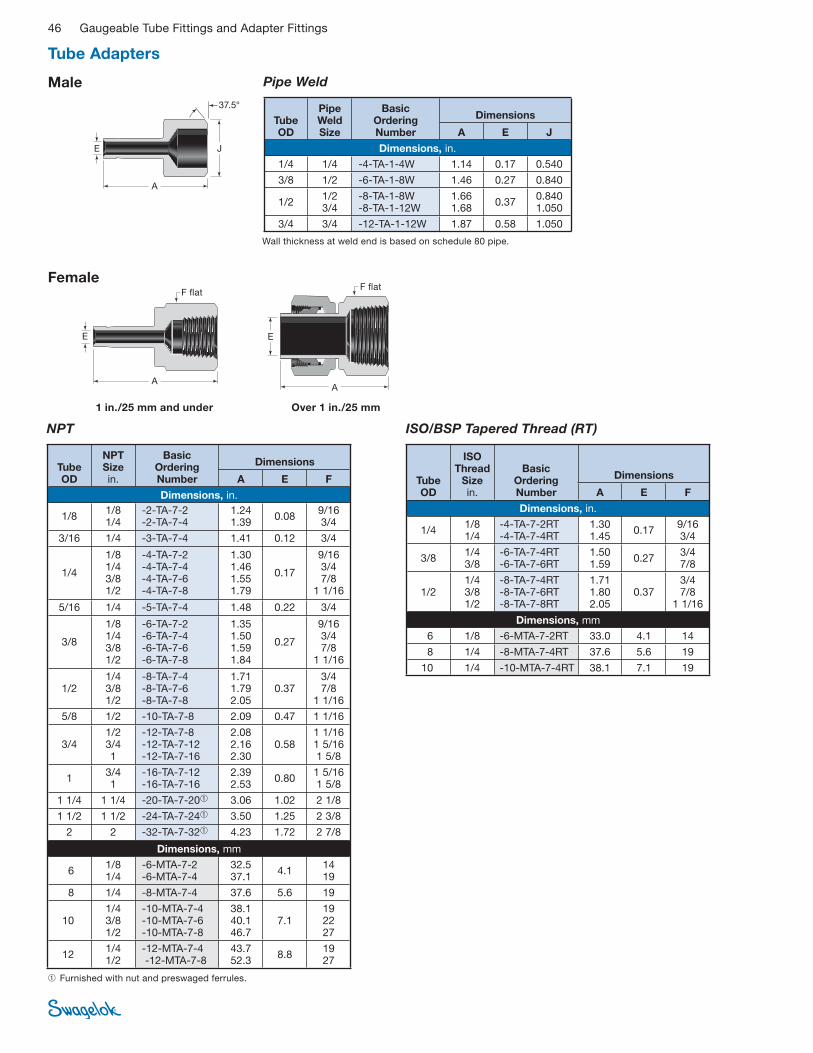
46 Gaugeable Tube Fittings and Adapter Fittings
Female
NPT ISO/BSP Tapered Thread (RT)
➀ Furnished with nut and preswaged ferrules.
1 in./25 mm and under
A
E
Over 1 in./25 mm
A
E
F fl atF fl at
Pipe Weld
A
JE
37.5°
Tube OD
Pipe Weld Size
Basic OrderingNumber
Dimensions
A E J
Dimensions, in.
1/4 1/4 -4-TA-1-4W 1.14 0.17 0.540
3/8 1/2 -6-TA-1-8W 1.46 0.27 0.840
1/2 1/2 3/4
-8-TA-1-8W -8-TA-1-12W
1.66 1.68
0.37 0.840 1.050
3/4 3/4 -12-TA-1-12W 1.87 0.58 1.050
Tube OD
NPT Size in.
Basic Ordering Number
Dimensions
A E F
Dimensions, in.
1/8 1/8 1/4
-2-TA-7-2 -2-TA-7-4
1.24 1.39
0.08 9/16 3/4
3/16 1/4 -3-TA-7-4 1.41 0.12 3/4
1/4
1/8 1/4 3/8 1/2
-4-TA-7-2 -4-TA-7-4 -4-TA-7-6 -4-TA-7-8
1.30 1.46 1.55 1.79
0.17
9/16 3/4 7/8
1 1/16
5/16 1/4 -5-TA-7-4 1.48 0.22 3/4
3/8
1/8 1/4 3/8 1/2
-6-TA-7-2 -6-TA-7-4 -6-TA-7-6 -6-TA-7-8
1.35 1.50 1.59 1.84
0.27
9/16 3/4 7/8
1 1/16
1/2 1/4 3/8 1/2
-8-TA-7-4 -8-TA-7-6 -8-TA-7-8
1.71 1.79 2.05
0.37 3/4 7/8
1 1/16
5/8 1/2 -10-TA-7-8 2.09 0.47 1 1/16
3/4 1/2 3/4 1
-12-TA-7-8 -12-TA-7-12 -12-TA-7-16
2.08 2.16 2.30
0.58 1 1/16 1 5/16 1 5/8
1 3/4 1
-16-TA-7-12 -16-TA-7-16
2.39 2.53
0.80 1 5/16 1 5/8
1 1/4 1 1/4 -20-TA-7-20➀ 3.06 1.02 2 1/8
1 1/2 1 1/2 -24-TA-7-24➀ 3.50 1.25 2 3/8
2 2 -32-TA-7-32➀ 4.23 1.72 2 7/8
Dimensions, mm
6 1/8 1/4
-6-MTA-7-2 -6-MTA-7-4
32.5 37.1
4.1 14 19
8 1/4 -8-MTA-7-4 37.6 5.6 19
10 1/4 3/8 1/2
-10-MTA-7-4 -10-MTA-7-6 -10-MTA-7-8
38.1 40.1 46.7
7.1 19 22 27
12 1/4 1/2
-12-MTA-7-4 -12-MTA-7-8
43.7 52.3
8.8 19 27
Tube OD
ISO Thread
Size in.
Basic Ordering Number
Dimensions
A E F
Dimensions, in.
1/4 1/8 1/4
-4-TA-7-2RT -4-TA-7-4RT
1.30 1.45
0.17 9/16 3/4
3/8 1/4 3/8
-6-TA-7-4RT -6-TA-7-6RT
1.50 1.59
0.27 3/4 7/8
1/2 1/4 3/8 1/2
-8-TA-7-4RT -8-TA-7-6RT -8-TA-7-8RT
1.71 1.80 2.05
0.37 3/4 7/8
1 1/16
Dimensions, mm
6 1/8 -6-MTA-7-2RT 33.0 4.1 14
8 1/4 -8-MTA-7-4RT 37.6 5.6 19
10 1/4 -10-MTA-7-4RT 38.1 7.1 19
Wall thickness at weld end is based on schedule 80 pipe.
Male
Tube Adapters
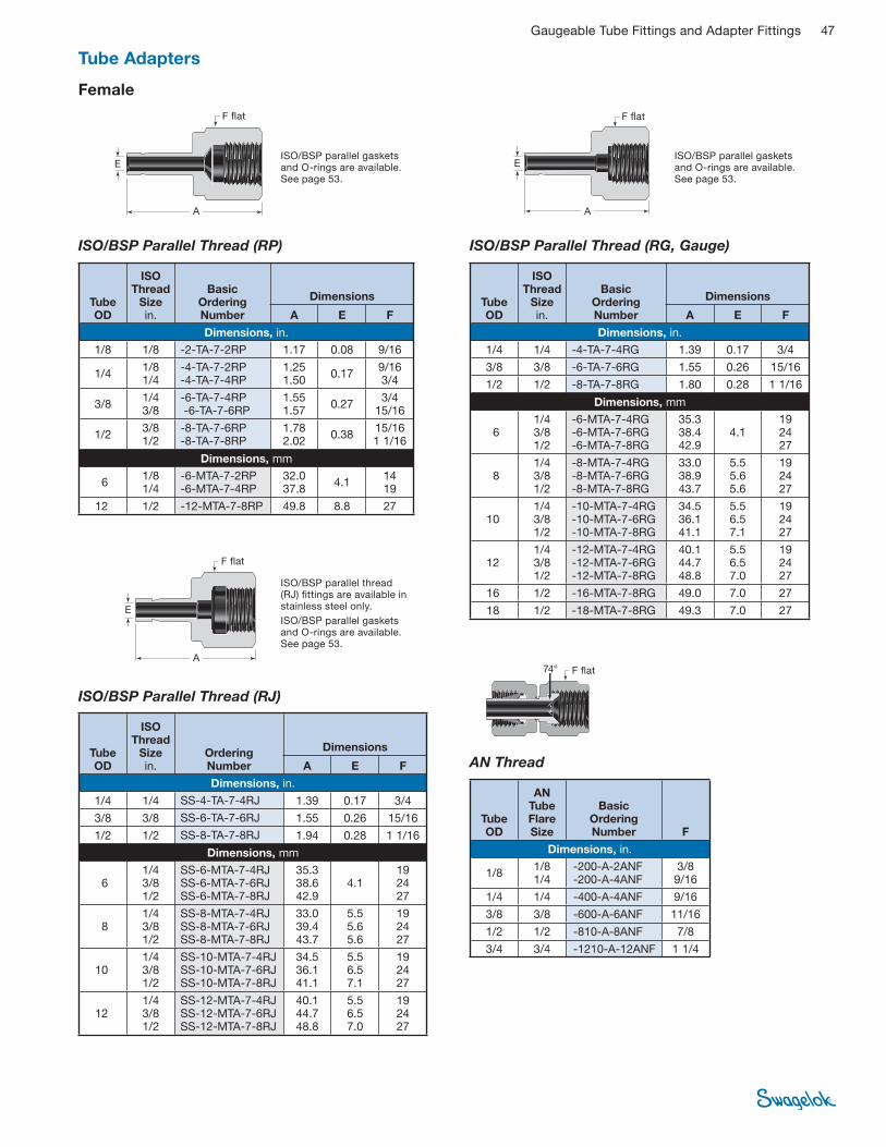
Gaugeable Tube Fittings and Adapter Fittings 47
Female
ISO/BSP Parallel Thread (RP)
ISO/BSP Parallel Thread (RJ)
ISO/BSP Parallel Thread (RG, Gauge)
AN Thread
74°
ISO/BSP parallel gaskets and O-rings are available. See page 53.
A
E
F fl at
A
E
F fl at
A
E
F fl at
F fl at
Tube OD
ISO Thread
Size in.
Basic Ordering Number
Dimensions
A E F
Dimensions, in.
1/8 1/8 -2-TA-7-2RP 1.17 0.08 9/16
1/4 1/8 1/4
-4-TA-7-2RP -4-TA-7-4RP
1.25 1.50
0.17 9/16 3/4
3/8 1/4 3/8
-6-TA-7-4RP -6-TA-7-6RP
1.55 1.57
0.27 3/4
15/16
1/2 3/8 1/2
-8-TA-7-6RP -8-TA-7-8RP
1.78 2.02
0.38 15/16 1 1/16
Dimensions, mm
6 1/8 1/4
-6-MTA-7-2RP -6-MTA-7-4RP
32.0 37.8
4.1 14 19
12 1/2 -12-MTA-7-8RP 49.8 8.8 27
Tube OD
ISO Thread
Size in.
Ordering Number
Dimensions
A E F
Dimensions, in.
1/4 1/4 SS-4-TA-7-4RJ 1.39 0.17 3/4
3/8 3/8 SS-6-TA-7-6RJ 1.55 0.26 15/16
1/2 1/2 SS-8-TA-7-8RJ 1.94 0.28 1 1/16
Dimensions, mm
6 1/4 3/8 1/2
SS-6-MTA-7-4RJ SS-6-MTA-7-6RJ SS-6-MTA-7-8RJ
35.3 38.6 42.9
4.1 19 24 27
8 1/4 3/8 1/2
SS-8-MTA-7-4RJ SS-8-MTA-7-6RJ SS-8-MTA-7-8RJ
33.0 39.4 43.7
5.5 5.6 5.6
19 24 27
101/4 3/8 1/2
SS-10-MTA-7-4RJ SS-10-MTA-7-6RJ SS-10-MTA-7-8RJ
34.5 36.1 41.1
5.5 6.5 7.1
19 24 27
121/4 3/8 1/2
SS-12-MTA-7-4RJ SS-12-MTA-7-6RJ SS-12-MTA-7-8RJ
40.1 44.7 48.8
5.5 6.5 7.0
19 24 27
Tube OD
ISO Thread
Size in.
Basic Ordering Number
Dimensions
A E F
Dimensions, in.
1/4 1/4 -4-TA-7-4RG 1.39 0.17 3/4
3/8 3/8 -6-TA-7-6RG 1.55 0.26 15/16
1/2 1/2 -8-TA-7-8RG 1.80 0.28 1 1/16
Dimensions, mm
6 1/4 3/8 1/2
-6-MTA-7-4RG -6-MTA-7-6RG -6-MTA-7-8RG
35.3 38.4 42.9
4.1 19 24 27
8 1/4 3/8 1/2
-8-MTA-7-4RG -8-MTA-7-6RG -8-MTA-7-8RG
33.0 38.9 43.7
5.5 5.6 5.6
19 24 27
10 1/4 3/8 1/2
-10-MTA-7-4RG -10-MTA-7-6RG -10-MTA-7-8RG
34.5 36.1 41.1
5.5 6.5 7.1
19 24 27
12 1/4 3/8 1/2
-12-MTA-7-4RG -12-MTA-7-6RG -12-MTA-7-8RG
40.1 44.7 48.8
5.5 6.5 7.0
19 24 27
16 1/2 -16-MTA-7-8RG 49.0 7.0 27
18 1/2 -18-MTA-7-8RG 49.3 7.0 27
Tube OD
AN Tube Flare Size
Basic Ordering Number F
Dimensions, in.
1/8 1/8 1/4
-200-A-2ANF -200-A-4ANF
3/8 9/16
1/4 1/4 -400-A-4ANF 9/16
3/8 3/8 -600-A-6ANF 11/16
1/2 1/2 -810-A-8ANF 7/8
3/4 3/4 -1210-A-12ANF 1 1/4
ISO/BSP parallel gaskets and O-rings are available. See page 53.
Tube Adapters
ISO/BSP parallel thread (RJ) fi ttings are available in stainless steel only.
ISO/BSP parallel gaskets and O-rings are available. See page 53.
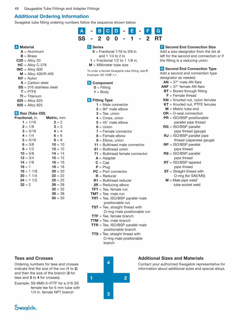
48 Gaugeable Tube Fittings and Adapter Fittings
SS - 2 0 0 - 1 - 2 RT
Additional Ordering InformationSwagelok tube fi tting ordering numbers follow the sequence shown below.
SS - 2 0 0 - 1 - 2 RT
Material
A = Aluminum
B = Brass
C20 = Alloy 20
HC = Alloy C-276
INC = Alloy 600
M = Alloy 400/R-405
NY = Nylon
S = Carbon steel
SS = 316 stainless steel
T = PTFE
TI = Titanium
625 = Alloy 625
825 = Alloy 825
A
Second End Connection Type
Add a second end connection type
designator as needed.
AN = 37° male AN fl are
ANF = 37° female AN fl are
BT = Bored-through fi tting
F = Female thread
KN = Knurled nut, nylon ferrules
KT = Knurled nut, PTFE ferrules
M = Metric tube end
OR = O-seal connection
PR = ISO/BSP positionable
parallel pipe thread
RG = ISO/BSP parallel
pipe thread (gauge)
RJ = ISO/BSP parallel pipe
thread (Japanese gauge)
RP = ISO/BSP parallel
pipe thread
RS = ISO/BSP parallel
pipe thread
RT = ISO/BSP tapered
pipe thread
ST = Straight thread with
O-ring (for SAE/MS)
W = Male pipe weld/
tube socket weld
G
Fitting Type
1 = Male connector
2 = 90° male elbow
3 = Tee, union
4 = Cross, union
5 = 45° male elbow
6 = Union
7 = Female connector
8 = Female elbow
9 = Elbow, union
11 = Bulkhead male connector
61 = Bulkhead union
71 = Bulkhead female connector
A = Adapter
C = Cap
P = Plug
PC = Port connector
R = Reducer
R1 = Bulkhead reducer
2R = Reducing elbow
TFT = Tee, female run
TMT = Tee, male run
TRT = Tee, ISO/BSP parallel male
positionable run
TST = Tee, straight thread with
O-ring male positionable run
TTF = Tee, female branch
TTM = Tee, male branch
TTR = Tee, ISO/BSP parallel male
positionable branch
TTS = Tee, straight thread with
O-ring male positionable
branch
E
Component
0 = Fitting
1 = Body
D
Fractional, in.
1 = 1/16
2 = 1/8
3 = 3/16
4 = 1/4
5 = 5/16
6 = 3/8
8 = 1/2
10 = 5/8
12 = 3/4
14 = 7/8
16 = 1
18 = 1 1/8
20 = 1 1/4
24 = 1 1/2
32 = 2
Metric, mm
2 = 2
3 = 3
4 = 4
6 = 6
8 = 8
10 = 10
12 = 12
14 = 14
15 = 15
16 = 16
18 = 18
20 = 20
22 = 22
25 = 25
28 = 28
32 = 32
38 = 38
50 = 50
Size (Tube OD)B
B DA C E G
To order a female Swagelok tube fitting, add F.
Example: SS-100F-1-1.
Series
0 = Fractional 1/16 to 3/8 in.
and 1 1/4 to 2 in.
1 = Fractional 1/2 to 1 1/8 in.
M = Millimeter tube size
C
F
Second End Connection Size
Add a size designator from the list at
left for the second end connection or if
the fi tting is a reducing union.
F
Tees and Crosses
Ordering numbers for tees and crosses
indicate fi rst the size of the run (1 to 2)
and then the size of the branch (3 for
tees and 3 to 4 for crosses).
Example: SS-6M0-3-4TTF for a 316 SS
female tee for 6 mm tube with
1/4 in. female NPT branch
1 2
3
4Additional Sizes and Materials
Contact your authorized Swagelok representative for
information about additional sizes and special alloys.

Gaugeable Tube Fittings and Adapter Fittings 49
SS - 2 - TA - 1 - 4 RT
Additional Ordering InformationSwagelok tube adapter ordering numbers follow the sequence shown below.
SS - 2 - TA - 1 - 4 RT
Adapter Type
1 = Male adapter
7 = Female adapter
D
Component
TA = Fractional tube adapter
MTA = Metric tube adapter
C
Fractional, in.
1 = 1/16
2 = 1/8
3 = 3/16
4 = 1/4
5 = 5/16
6 = 3/8
8 = 1/2
10 = 5/8
12 = 3/4
14 = 7/8
16 = 1
18 = 1 1/8
20 = 1 1/4
24 = 1 1/2
32 = 2
Metric, mm
2 = 2
3 = 3
4 = 4
6 = 6
8 = 8
10 = 10
12 = 12
14 = 14
15 = 15
16 = 16
18 = 18
20 = 20
22 = 22
25 = 25
28 = 28
32 = 32
38 = 38
50 = 50
Size (Tube OD)B
B CA D F
Second End Connection Type
Add a second end connection type
designator as needed.
AN = 37° male AN fl are
ANF = 37° female AN fl are
RG = ISO/BSP parallel pipe
thread (gauge)
RJ = ISO/BSP parallel pipe
thread (Japanese gauge)
RP = ISO/BSP parallel
pipe thread
RS = ISO/BSP parallel
pipe thread
RT = ISO/BSP tapered
pipe thread
ST = Straight thread with
O-ring (for SAE/MS)
W = Male pipe weld/
tube socket weld
F
E
Second End Connection Size
Add a size designator from the list at
left for the second end connection.
EMaterial
A = Aluminum
B = Brass
C20 = Alloy 20
HC = Alloy C-276
INC = Alloy 600
M = Alloy 400/R-405
NY = Nylon
S = Carbon steel
SS = 316 stainless steel
T = PTFE
TI = Titanium
625 = Alloy 625
825 = Alloy 825
A
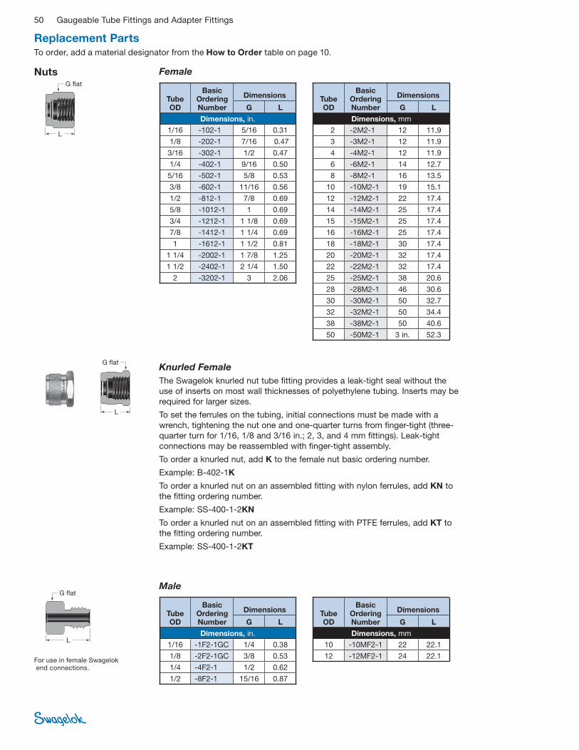
50 Gaugeable Tube Fittings and Adapter Fittings
Nuts
Knurled Female
The Swagelok knurled nut tube fi tting provides a leak-tight seal without the
use of inserts on most wall thicknesses of polyethylene tubing. Inserts may be
required for larger sizes.
To set the ferrules on the tubing, initial connections must be made with a
wrench, tightening the nut one and one-quarter turns from fi nger-tight (three-
quarter turn for 1/16, 1/8 and 3/16 in.; 2, 3, and 4 mm fi ttings). Leak-tight
connections may be reassembled with fi nger-tight assembly.
To order a knurled nut, add K to the female nut basic ordering number.
Example: B-402-1K
To order a knurled nut on an assembled fi tting with nylon ferrules, add KN to
the fi tting ordering number.
Example: SS-400-1-2KN
To order a knurled nut on an assembled fi tting with PTFE ferrules, add KT to
the fi tting ordering number.
Example: SS-400-1-2KT
Female
L
G fl at
L
G fl at
Replacement PartsTo order, add a material designator from the How to Order table on page 10.
Tube OD
Basic Ordering Number
Dimensions
G L
Dimensions, in.
1/16 -102-1 5/16 0.31
1/8 -202-1 7/16 0.47
3/16 -302-1 1/2 0.47
1/4 -402-1 9/16 0.50
5/16 -502-1 5/8 0.53
3/8 -602-1 11/16 0.56
1/2 -812-1 7/8 0.69
5/8 -1012-1 1 0.69
3/4 -1212-1 1 1/8 0.69
7/8 -1412-1 1 1/4 0.69
1 -1612-1 1 1/2 0.81
1 1/4 -2002-1 1 7/8 1.25
1 1/2 -2402-1 2 1/4 1.50
2 -3202-1 3 2.06
Tube OD
Basic Ordering Number
Dimensions
G L
Dimensions, mm
2 -2M2-1 12 11.9
3 -3M2-1 12 11.9
4 -4M2-1 12 11.9
6 -6M2-1 14 12.7
8 -8M2-1 16 13.5
10 -10M2-1 19 15.1
12 -12M2-1 22 17.4
14 -14M2-1 25 17.4
15 -15M2-1 25 17.4
16 -16M2-1 25 17.4
18 -18M2-1 30 17.4
20 -20M2-1 32 17.4
22 -22M2-1 32 17.4
25 -25M2-1 38 20.6
28 -28M2-1 46 30.6
30 -30M2-1 50 32.7
32 -32M2-1 50 34.4
38 -38M2-1 50 40.6
50 -50M2-1 3 in. 52.3
For use in female Swagelok end connections.
Male
L
Tube OD
Basic Ordering Number
Dimensions
G L
Dimensions, in.
1/16 -1F2-1GC 1/4 0.38
1/8 -2F2-1GC 3/8 0.53
1/4 -4F2-1 1/2 0.62
1/2 -8F2-1 15/16 0.87
Tube OD
Basic Ordering Number
Dimensions
G L
Dimensions, mm
10 -10MF2-1 22 22.1
12 -12MF2-1 24 22.1
G fl at

Gaugeable Tube Fittings and Adapter Fittings 51
Ferrules
Front Back
➀ Over 1 in. and over 25 mm stainless steel front ferrules are PFA coated. To order silver-plated front ferrules, add -BL to the basic ordering number.
Example: SS-2003-1-BL
➀ Over 1 in. and over 25 mm stainless steel back ferrules are PFA coated. To order back ferrules without PFA coating, add -WC to the basic ordering number.
Example: SS-2004-1-WC
Tube OD
Basic Ordering Number
Dimensions, in.
1/16 -103-1
1/8 -203-1
3/16 -303-1
1/4 -403-1
5/16 -503-1
3/8 -603-1
1/2 -813-1
5/8 -1013-1
3/4 -1213-1
7/8 -1413-1
1 -1613-1
1 1/4 -2003-1➀
1 1/2 -2403-1➀
2 -3203-1➀
Tube OD
Basic Ordering Number
Dimensions, mm
2 -2M3-1
3 -3M3-1
4 -4M3-1
6 -6M3-1
8 -8M3-1
10 -10M3-1
12 -12M3-1
14 -14M3-1
15 -15M3-1
16 -16M3-1
18 -18M3-1
20 -20M3-1
22 -22M3-1
25 -25M3-1
28 -28M3-1➀
30 -30M3-1➀
32 -32M3-1➀
38 -38M3-1➀
50 -50M3-1➀
Tube OD
Basic Ordering Number
Dimensions, in.
1/16 -104-1
1/8 -204-1
3/16 -304-1
1/4 -404-1
5/16 -504-1
3/8 -604-1
1/2 -814-1
5/8 -1014-1
3/4 -1214-1
7/8 -1414-1
1 -1614-1
1 1/4 -2004-1➀
1 1/2 -2404-1➀
2 -3204-1➀
Tube OD
Basic Ordering Number
Dimensions, mm
2 -2M4-1
3 -3M4-1
4 -4M4-1
6 -6M4-1
8 -8M4-1
10 -10M4-1
12 -12M4-1
14 -14M4-1
15 -15M4-1
16 -16M4-1
18 -18M4-1
20 -20M4-1
22 -22M4-1
25 -25M4-1
28 -28M4-1➀
30 -30M4-1➀
32 -32M4-1➀
38 -38M4-1➀
50 -50M4-1➀
Replacement PartsTo order, add a material designator from the How to Order table on page 10.
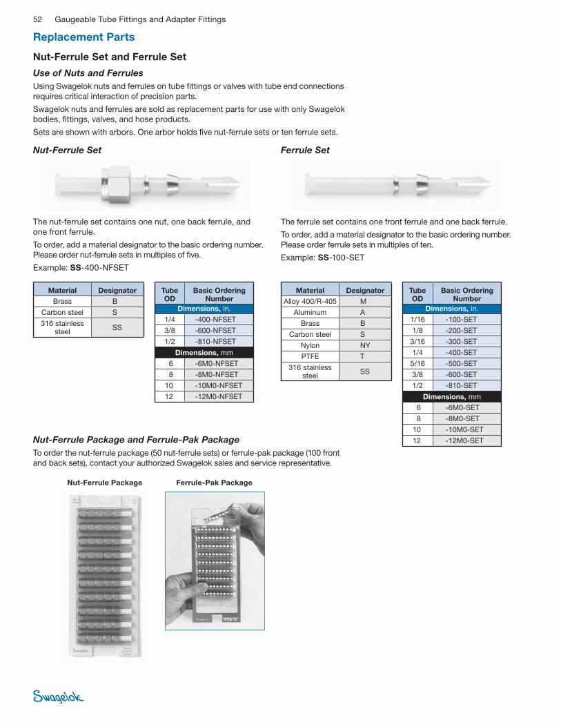
52 Gaugeable Tube Fittings and Adapter Fittings
Nut-Ferrule Set and Ferrule Set
Ferrule Set
The ferrule set contains one front ferrule and one back ferrule.
To order, add a material designator to the basic ordering number.
Please order ferrule sets in multiples of ten.
Example: SS-100-SET
Nut-Ferrule Set
The nut-ferrule set contains one nut, one back ferrule, and
one front ferrule.
To order, add a material designator to the basic ordering number.
Please order nut-ferrule sets in multiples of fi ve.
Example: SS-400-NFSET
Use of Nuts and Ferrules
Using Swagelok nuts and ferrules on tube fi ttings or valves with tube end connections
requires critical interaction of precision parts.
Swagelok nuts and ferrules are sold as replacement parts for use with only Swagelok
bodies, fi ttings, valves, and hose products.
Sets are shown with arbors. One arbor holds fi ve nut-ferrule sets or ten ferrule sets.
Nut-Ferrule Package and Ferrule-Pak Package
To order the nut-ferrule package (50 nut-ferrule sets) or ferrule-pak package (100 front
and back sets), contact your authorized Swagelok sales and service representative.
Ferrule-Pak PackageNut-Ferrule Package
Material Designator
Brass B
Carbon steel S
316 stainless steel
SS
Tube OD
Basic Ordering Number
Dimensions, in.
1/4 -400-NFSET
3/8 -600-NFSET
1/2 -810-NFSET
Dimensions, mm
6 -6M0-NFSET
8 -8M0-NFSET
10 -10M0-NFSET
12 -12M0-NFSET
Material Designator
Alloy 400/R-405 M
Aluminum A
Brass B
Carbon steel S
Nylon NY
PTFE T
316 stainless steel
SS
Tube OD
Basic Ordering Number
Dimensions, in.
1/16 -100-SET
1/8 -200-SET
3/16 -300-SET
1/4 -400-SET
5/16 -500-SET
3/8 -600-SET
1/2 -810-SET
Dimensions, mm
6 -6M0-SET
8 -8M0-SET
10 -10M0-SET
12 -12M0-SET
Replacement Parts

Gaugeable Tube Fittings and Adapter Fittings 53
ISO/BSP Parallel Gaskets
Steel (RS Fitting)
The RS fi tting steel gasket provides a seal
with male ISO/BSP parallel threads. The
gasket consists of a fl uorocarbon FKM or
Buna inner ring bonded to a carbon steel
outer ring. To order, add V for fl uorocarbon
FKM or B for Buna to the basic ordering
number.
Example: S-2-RS-2B
For use only with Swagelok RS fi ttings.
H
E Tx
➀ Also available with fl uorocarbon FKM inner ring bonded to a stainless steel outer ring. To order, replace S with SS in the basic ordering number.
Example: SS-8-RS-2V
Gasket
ISO Thread
Size
Basic OrderingNumber
Dimensions
E H Tx
Dimensions, in.
1/8 S-2-RS-2 0.41
0.08
0.63
1/4 S-4-RS-2➀ 0.54 0.81
3/8 S-6-RS-2➀ 0.68 0.94
1/2 S-8-RS-2➀ 0.85
0.10
1.13
3/4 S-12-RS-2 1.06 1.38
1 S-16-RS-2 1.33 1.69
Copper (RP Fitting)
The RP fi tting copper gasket provides a
seal with male ISO/BSP parallel threads.
May be used with a Swagelok RS fi tting.H
E Tx
Gasket
ISO Thread
Size OrderingNumber
Dimensions
E H Tx
Dimensions, in.
1/8 CU-2-RP-2 0.39 0.04 0.59
1/4 CU-4-RP-2 0.52
0.06
0.75
3/8 CU-6-RP-2 0.66 0.91
1/2 CU-8-RP-2 0.83 1.06
3/4 CU-12-RP-2 1.05 0.08
1.30
1 CU-16-RP-2 1.31 1.58
Copper (RG, Gauge Fitting)
The RG fi tting copper gasket provides
a seal on pressure gauges equipped with
ISO/BSP parallel male threads.
H
E Tx
GasketISO
Thread Size
OrderingNumber
Dimensions
E H Tx
Dimensions, in.
1/4 CU-4-RG-2 0.30 0.07 0.42
3/8 CU-6-RG-2 0.34 0.09 0.56
1/2 CU-8-RG-2 0.36 0.10 0.70
ISO Thread
Size in.
OrderingNumber
Dimensions
E H Tx
Dimensions, mm
Regular Gaskets
1/4 T-4-RJ-2
5.6 1.0
10.9
3/8 T-6-RJ-2 13.9
1/2 T-8-RJ-2 17.8
Thick Gaskets
1/4 T-4-RJ-2-T
5.6
4.1 10.9
3/8 T-6-RJ-2-T 4.6 13.9
1/2 T-8-RJ-2-T 5.1 17.8
PTFE (RJ Fitting)
The RJ fi tting PTFE gasket provides
a seal with ISO/BSP parallel male threads.
Replacement Parts
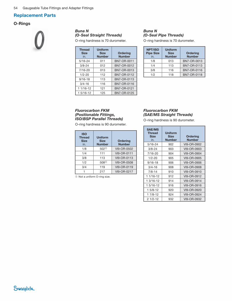
54 Gaugeable Tube Fittings and Adapter Fittings
O-Rings
Fluorocarbon FKM(Positionable Fittings, ISO/BSP Parallel Threads)
O-ring hardness is 90 durometer.
Buna N (O-Seal Straight Threads)
O-ring hardness is 70 durometer.
Thread Size in.
Uniform Size
Number Ordering Number
5/16-24 011 BN7-OR-0011
3/8-24 012 BN7-OR-0012
7/16-20 013 BN7-OR-0013
1/2-20 112 BN7-OR-0112
9/16-18 113 BN7-OR-0113
3/4-16 116 BN7-OR-0116
1 1/16-12 121 BN7-OR-0121
1 5/16-12 125 BN7-OR-0125
➀ Not a uniform O-ring size.
ISO Thread
Size in.
Uniform Size
Number Ordering Number
1/8 502➀ VI9-OR-0502
1/4 111 VI9-OR-0111
3/8 113 VI9-OR-0113
1/2 508➀ VI9-OR-0508
3/4 119 VI9-OR-0119
1 217 VI9-OR-0217
Buna N (O-Seal Pipe Threads)
O-ring hardness is 70 durometer.
Fluorocarbon FKM (SAE/MS Straight Threads)
O-ring hardness is 90 durometer.
NPT/ISO Pipe Size
in.
Uniform Size
Number Ordering Number
1/8 013 BN7-OR-0013
1/4 113 BN7-OR-0113
3/8 116 BN7-OR-0116
1/2 118 BN7-OR-0118
SAE/MS Thread
Size in.
Uniform Size
Number Ordering Number
5/16-24 902 VI9-OR-0902
3/8-24 903 VI9-OR-0903
7/16-20 904 VI9-OR-0904
1/2-20 905 VI9-OR-0905
9/16-18 906 VI9-OR-0906
3/4-16 908 VI9-OR-0908
7/8-14 910 VI9-OR-0910
1 1/16-12 912 VI9-OR-0912
1 3/16-12 914 VI9-OR-0914
1 5/16-12 916 VI9-OR-0916
1 5/8-12 920 VI9-OR-0920
1 7/8-12 924 VI9-OR-0924
2 1/2-12 932 VI9-OR-0932
Replacement Parts

Gaugeable Tube Fittings and Adapter Fittings 55
Swagelok gap inspection gauges assure the installer or
inspector that the fi tting has been suffi ciently pulled up
on initial installation, whether using a multihead hydraulic
swaging unit (MHSU) or air-actuated hydraulic swaging
unit (AHSU), or wrench tightening. All metal Swagelok tube
fi ttings are gaugeable, with the exception of a few forged
bodies in aluminum.
Gap Inspection Gauge
For Installation Using the MHSU
➀ The MHSU cannot be used for SAF 2507 tubing 1/2 in. and under or for medium pressure tubing.
➁ For 5/8 and 3/4 in. SAF 2507 tubing, order the 1 in. (25 mm) and over unit and SAF 2507 tooling and gauge.
For Installation Using the AHSU
Fitting Size
Ordering Number in. mm
Female Nut
1/4, 3/8, 1/2 — MS-AHSU-IG-468
— 6, 8, 10, 12 MS-AHSU-IG-612M
Fitting Size
Ordering Number in. mm
Female Nut
1/2➀ 12 MS-MHSU-IG-810
5/8➁ 14, 15, 16 MS-MHSU-IG-1010
5/8 (SAF 2507) — MS-MHSU-IG-2507-1010
3/4➁ 18 MS-MHSU-IG-1210
3/4 (SAF 2507) — MS-MHSU-IG-2507-1210
7/8 20, 22 MS-MHSU-IG-1410
1 25 MS-MHSU-IG-1610-1
— 28 MS-MHSU-IG-28M0-1
30 MS-MHSU-IG-30M0-1
1 1/4 — MS-MHSU-IG-2000-2
— 32 MS-MHSU-IG-32M0-1
— 38 MS-MHSU-IG-38M0-1
1 1/2 — MS-MHSU-IG-2400-1
— 50 MS-MHSU-IG-50M0-1
2 — MS-MHSU-IG-3200-1
Tools and Accessories
Depth Marking Tool
Swagelok depth
marking tools help
ensure that tubing
is bottomed on the
shoulder inside
the Swagelok tube
fi tting body.
Tube OD
Ordering Number
Dimensions, in.
1/4 MS-DMT-400
3/8 MS-DMT-600
1/2 MS-DMT-810
5/8 MS-DMT-1010
3/4 MS-DMT-1210
7/8 MS-DMT-1410
1 MS-DMT-1610
Tube OD
Ordering Number
Dimensions, mm
6 MS-DMT-6M0
8 MS-DMT-8M0
10 MS-DMT-10M0
12 MS-DMT-12M0
16 MS-DMT-16M0
18 MS-DMT-18M0
For Installation Using a Wrench
Fitting Size Ordering Number in. mm
Female Nut
1/16 — MS-IG-100
1/8 2, 3 MS-IG-200
3/16 4 MS-IG-300
1/4 6 MS-IG-400
1/4, 3/8, 1/2 6, 12 MS-IG-468
1/4, 1/2 6, 8, 10, 12 MS-IG-612M
5/16 8 MS-IG-500
3/8 — MS-IG-600
— 10 MS-IG-10M0
1/2 12 MS-IG-810
5/8 14, 15, 16 MS-IG-1010
5/8 (SAF 2507) — MS-IG-2507-1010
3/4 18 MS-IG-1210
3/4 (SAF 2507) — MS-IG-2507-1210
7/8 20, 22 MS-IG-1410
1 25 MS-IG-1610
Male Nut
1/16 — MS-IG-1F0
1/8 2, 3 MS-IG-2F0
1/4, 3/8, 1/2 (medium-pressure)
— MS-IG-FK0

56 Gaugeable Tube Fittings and Adapter Fittings
Insert for Soft Plastic Tubing
Ordering Information
Add the insert material
designator to the basic
ordering number.
Example: B-305-2
ID ofbore
Tube ID
Tube OD
Swagelok inserts help secure soft plastic tubing being used
with standard Swagelok tube fi ttings. To determine the
correct size of the Swagelok insert to be used, check both
outside diameter and inside diameter of the plastic tubing.
For a complete line of hose connectors for soft plastic tubing,
see the Swagelok Hose Connectors, Accessories, and Hose
Adapters catalog, MS-01-27.
Tube OD
Tube ID
Bore ID
Basic Ordering Number
Dimensions, in.
3/16 1/8 0.09 -305-2
1/4
1/8 0.09 -405-2
0.17 0.11 -405-170
3/16 0.14 -405-3
5/16
1/8 0.09 -505-2
3/16 0.12 -505-3
1/4 0.19 -505-4
3/8 3/16 0.12 -605-3
1/4 0.19 -605-4
1/2 1/4 0.19 -815-4
3/8 0.31 -815-6
5/8 3/8 0.31 -1015-6
1/2 0.44 -1015-8
3/4 1/2 0.44 -1215-8
5/8 0.56 -1215-10
1 3/4 0.69 -1615-12
Dimensions, mm
6 4 2.8 -6M5-4M
8 6 4.4 -8M5-6M
10 8 6.4 -10M5-8M
12 8 6.4 -12M5-8M
10 8.3 -12M5-10M
Material Designator
Alloy 400/R-405 M
Aluminum A
Brass B
Carbon steel S
Nylon NY
Stainless steel SS
Bulkhead Retainer
By using the bulkhead retainer,
one person can tighten the jam
nut on side A for initial bulkhead
fi tting installation. Now tubing
can be connected to side A
and B by one person with one
wrench, because the bulkhead
retainer acts as a backup wrench.
Bulkhead fitting installation utilizing bulkhead retainer
Side AJam nut
Body hex
Bulkhead retainer
“U” drive screw
Side B
"U" drive screw
(included)
B
A
E
D
1/8 in.
F
Fitting Size Ordering
Number
Dimensions, in. “U” Drive Screw Size
Drill Number A B D E F
Drill Hole Dia in. mm
1/16 — SS-102-61F 3/8 5/16 5/16 5/32
5/32 0.120 6-3/8 31
1/8 — SS-202-61F 1/2 1/2 13/32 7/32
3/16 3, 4 SS-302-61F 9/16 9/16 15/32 1/4
1/4 6 SS-402-61F 5/8 5/8 1/2 9/32
5/16 — SS-502-61F 11/16 11/16 9/16 5/16
— 8 SS-8M2-61F 11/16 18 mm 9/16 5/16
3/8 — SS-602-61F 3/4 3/4 5/8 11/32
— 10 SS-10M2-61F 15/16 22 mm 3/4 13/32
7/32 0.144 10-1/2 27
1/2 12 SS-812-61F 15/16 15/16 3/4 13/32
5/8 15, 16 SS-1012-61F 1 1 1/16 13/16 13/32
3/4 18 SS-1212-61F 1 1/16 1 3/16 29/32 15/32
7/8 — SS-1412-61F 1 1/8 1 5/16 1 1/32 17/32
1 — SS-1612-61F 1 9/32 1 5/8 1 5/32 9/16
Tools and Accessories

Gaugeable Tube Fittings and Adapter Fittings 57
Hydraulic Swaging Units Multihead (MHSU)
■ Preswages Swagelok ferrules onto
tubing
■ Provides Swagelok tube fi tting
connections that are 100 % gaugeable
upon initial installation. Use MHSU
gap inspection gauges supplied with
the unit.
■ Is available in two unit sizes, with a
choice of interchangeable fractional
or metric tooling for:
■ 1/2 to 1 in. and 12 to 25 mm tubing
and tube adapters
■ 1 to 2 in. and 25 to 50 mm tubing
and tube adapters
■ Places no initial strain on nut or fi tting
body threads or on body seal surfaces
■ Must be used to install 1 1/4, 1 1/2,
and 2 in. and 28, 30, 32, 38, and
50 mm Swagelok tube fi ttings
■ Is standard with a tube marking
feature to indicate when tube is
properly bottomed in the unit
■ Is available with a support base
(as shown) and with stainless
steel connection tubing in place of
hydraulic hose.
■ Fits neatly in a rugged plastic
carrying case
■ Reduces assembly and installation
time and operator error.
For additional information, see the Swagelok Hydraulic Swaging Units—Multihead
(MHSU) catalog, MS-02 -154. For instructions, see Multihead Hydraulic Swaging
Unit (MHSU) Setup and Operation Instructions, MS-12-37.
The MHSU cannot be used for
SAF 2507 (super duplex) tubing
1/2 in. and under or for medium-
pressure tubing.
For 5/8 and 3/4 in. SAF 2507 tubing,
order the 1 in./25 mm and over unit and
SAF 2507 tooling and gauges.
Air-Actuated (AHSU)
■ Preswages Swagelok ferrules onto
tubing
■ Provides Swagelok tube fi tting
connections that are 100 %
gaugeable upon initial installation
■ Requires only one unit with
interchangeable tooling to swage 1/4
to 1/2 in. and 6 to 12 mm Swagelok
tube fi tting ferrule sizes
■ Places no initial strain on nut or
fi tting body threads or on body seal
surfaces
■ Requires no threading of nut on or off
the tooling
■ Fits neatly in a rugged plastic
carrying case
■ Reduces assembly and installation
time and operator error.
For additional information, see the Swagelok Hydraulic Swaging Units—Air-
Actuated (AHSU) catalog, MS-02-155. For instructions, see Air-Actuated Hydraulic
Swaging Unit (AHSU) Setup and Operation Instructions, MS-12-38.
The AHSU cannot be used for SAF
2507 (super duplex) tubing or for
medium-pressure tubing.
Preswaging Tool
For Swagelok tube fi tting installations in
close quarters, the Swagelok preswaging
tool is a convenient accessory.
Tube OD mm
Ordering Number
Female Nut
3 MS-ST-3M0
4 MS-ST-4M0
6 MS-ST-6M0
8 MS-ST-8M0
10 MS-ST-10M0
12 MS-ST-12M0
14 MS-ST-14M0
15 MS-ST-15M0
16 MS-ST-16M0
18 MS-ST-18M0
20 MS-ST-20M0
22 MS-ST-22M0
25 MS-ST-25M0
Tools and Accessories
Tube OD in.
Ordering Number
Female Nut
1/16 MS-ST-100
1/8 MS-ST-200
3/16 MS-ST-300
1/4 MS-ST-400
5/16 MS-ST-500
3/8 MS-ST-600
1/2 MS-ST-810
5/8 MS-ST-1010
5/8 (SAF 2507) MS-ST-2507-1010
3/4 MS-ST-1210
3/4 (SAF 2507) MS-ST-2507-1210
7/8 MS-ST-1410
1 MS-ST-1610
Male Nut
1/16 MS-ST-1F0
1/4 (medium-pressure) MS-ST-4FK0
3/8 (medium-pressure) MS-ST-6FK0
1/2 MS-ST-8F0
1/2 (medium-pressure) MS-ST-8FK0

58 Gaugeable Tube Fittings and Adapter Fittings
Installation InstructionsSwagelok tube fi ttings 1 in./25 mm and smaller can be installed quickly, easily, and reliably with simple hand tools.
Over 1 in./25 mm sizes require use of a hydraulic swaging unit to swage the ferrules onto the tubing.
Safety Precautions
■ Do not bleed system by loosening fi tting nut or fi tting plug.
■ Do not make up and tighten fi ttings when system is
pressurized.
■ Make sure that the tubing rests fi rmly on the shoulder of
the tube fi tting body before tightening the nut.
■ Use Swagelok gap inspection gauge to ensure suffi cient
pull-up upon initial installation.
■ Always use proper thread sealants on tapered pipe threads.
■ Do not mix materials or fi tting components from various
manufacturers—tubing, ferrules, nuts, and fi tting bodies.
■ Never turn fi tting body. Instead, hold fi tting body and turn nut.
■ Avoid unnecessary disassembly of unused fi ttings.
■ Use only long reducers in female Swagelok end connections.
See the instructions starting on the next page for installation
of Swagelok tube fi ttings, caps and plugs, port connectors,
tube adapters, O-seal male connectors, positionable elbows
and tees, preswaging tool, and weld fi ttings.
Tubing Considerations
■ Metal tubing material should be softer than fi tting material.
For example, stainless steel tubing should not be used with
brass fi ttings.
■ When tubing and fi ttings are made of the same material,
tubing must be fully annealed.
■ Always use an insert with extremely soft or pliable plastic
tubing.
■ Extremes of wall thickness should always be checked
against the suggested minimum and maximum wall
thickness limitations.
■ Surface fi nish is very important to proper sealing. Tubing
with any kind of depression, scratch, raised portion, or
other surface defect will be diffi cult to seal, particularly in
gas service.
■ Tubing that is oval and will not easily fi t through fi tting nuts,
ferrules, and bodies should never be forced into the fi tting.
See Swagelok Tubing Data, MS-01-107, for more information
about tubing selection.
GaugeabilityOn initial installation, the Swagelok gap inspection gauge
assures the installer or inspector that a fi tting has been
suffi ciently tightened.
� Always depressurize a system before adjusting the
tightness of a tube fi tting connection.
Position the Swagelok gap inspection gauge next to the gap between the nut and body.
If the gauge will enter the gap,
additional tightening is required.
If the gauge will not enter the gap, the
fi tting is suffi ciently tightened.
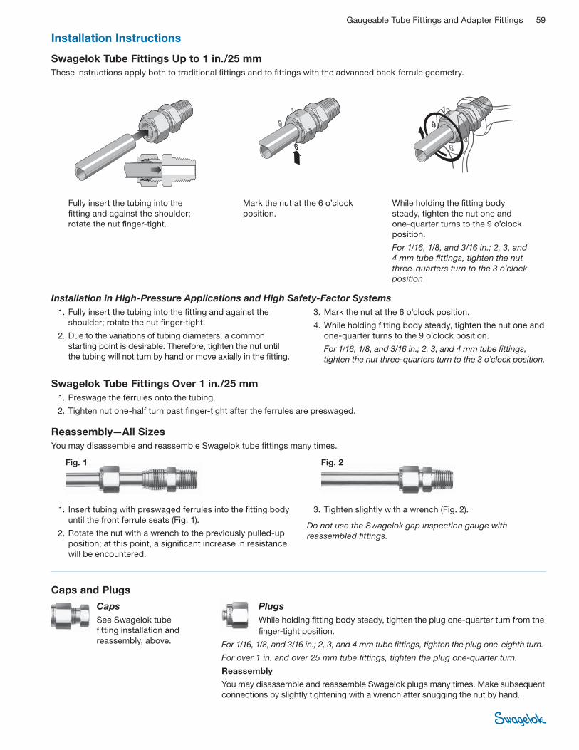
Gaugeable Tube Fittings and Adapter Fittings 59
Swagelok Tube Fittings Over 1 in./25 mm
1. Preswage the ferrules onto the tubing.
2. Tighten nut one-half turn past fi nger-tight after the ferrules are preswaged.
Swagelok Tube Fittings Up to 1 in./25 mm
These instructions apply both to traditional fi ttings and to fi ttings with the advanced back-ferrule geometry.
Installation Instructions
1. Fully insert the tubing into the fi tting and against the
shoulder; rotate the nut fi nger-tight.
2. Due to the variations of tubing diameters, a common
starting point is desirable. Therefore, tighten the nut until
the tubing will not turn by hand or move axially in the fi tting.
3. Mark the nut at the 6 o’clock position.
4. While holding fi tting body steady, tighten the nut one and
one-quarter turns to the 9 o’clock position.
For 1/16, 1/8, and 3/16 in.; 2, 3, and 4 mm tube fi ttings,
tighten the nut three-quarters turn to the 3 o’clock position.
Installation in High-Pressure Applications and High Safety-Factor Systems
Fig. 2Fig. 1
1. Insert tubing with preswaged ferrules into the fi tting body
until the front ferrule seats (Fig. 1).
2. Rotate the nut with a wrench to the previously pulled-up
position; at this point, a signifi cant increase in resistance
will be encountered.
3. Tighten slightly with a wrench (Fig. 2).
Do not use the Swagelok gap inspection gauge with
reassembled fi ttings.
Reassembly—All Sizes
You may disassemble and reassemble Swagelok tube fi ttings many times.
Fully insert the tubing into the
fi tting and against the shoulder;
rotate the nut fi nger-tight.
Mark the nut at the 6 o’clock
position.
While holding the fi tting body
steady, tighten the nut one and
one-quarter turns to the 9 o’clock
position.
For 1/16, 1/8, and 3/16 in.; 2, 3, and
4 mm tube fi ttings, tighten the nut
three-quarters turn to the 3 o’clock
position
Caps and Plugs
Caps
See Swagelok tube
fi tting installation and
reassembly, above.
Plugs
While holding fi tting body steady, tighten the plug one-quarter turn from the
fi nger-tight position.
For 1/16, 1/8, and 3/16 in.; 2, 3, and 4 mm tube fi ttings, tighten the plug one-eighth turn.
For over 1 in. and over 25 mm tube fi ttings, tighten the plug one-quarter turn.
Reassembly
You may disassemble and reassemble Swagelok plugs many times. Make subsequent
connections by slightly tightening with a wrench after snugging the nut by hand.

60 Gaugeable Tube Fittings and Adapter Fittings
1. Install the end opposite the tube
adapter end (Fig. 1).
2. Insert the tube adapter into the
Swagelok tube fi tting. Make sure
that the tube adapter rests fi rmly
on the shoulder of the tube fi tting
body and that the nut is fi nger-tight
(Fig. 2).
3. Mark the nut at the 6 o’clock
position.
4. While holding fi tting body steady,
tighten the nut one and one-
quarter turns to the 9 o’clock
position.
For 1/16, 1/8, and 3/16 in.; 2, 3, and
4 mm tube fi ttings, tighten the nut
three-quarters turn to the 3 o’clock
position.
Reassembly
See Swagelok tube fi tting reassembly,
page 59.
Female pipe port
on existing equipment
Fig. 1
Fig. 2
Tube Adapters
Installation Instructions
Fig. 1 Fig. 2 Fig. 3
Port Connectors
Machined Ferrule End
While holding fi tting body steady, tighten the port connector
one-quarter turn from the fi nger-tight position.
For 1/16, 1/8, and 3/16 in.; 2, 3, and 4 mm tube fi ttings, tighten
the port connector one-eighth turn.
For over 1 in. and over 25 mm tube fi ttings, tighten the port
connector one-quarter turn.
Reassembly
You may disassemble and reassemble Swagelok port
connectors many times. Make subsequent connections by
slightly tightening with a wrench after snugging the nut by hand.
Tube Adapter End
1. Insert the tube adapter into the Swagelok tube fi tting.
Make sure that the tube adapter rests fi rmly on the
shoulder of the tube fi tting body and that the nut is
fi nger-tight (Fig. 3).
2. Mark the nut at the 6 o’clock position.
3. While holding fi tting body steady, tighten the nut one and
one-quarter turns to the 9 o’clock position.
For 1/16, 1/8, and 3/16 in.; 2, 3, and 4 mm tube fi ttings,
tighten the nut three-quarters turn to the 3 o’clock position.
Reassembly
See Swagelok tube fi tting reassembly, page 59.
Positionable Elbows and Tees
Lock nut Backupwasher
1. Turn the positionable end into the female fi tting until the metal backup washer
contacts the face of the fi tting.
2. Turn the positionable end out of the female fi tting (not more than one turn) until
the Swagelok tube fi tting end is positioned properly.
3. While holding fi tting body steady, tighten the lock nut until the metal backup
washer contacts the face of the fi tting.
O-Seal Male Connectors
1. Turn the O-seal connector into the female end until it is fi nger-tight.
2. Tighten the O-seal connector until it makes metal-to-metal contact with the
face of the female end.
3. Tighten slightly with a wrench.
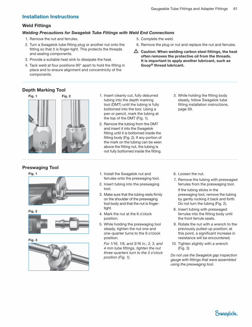
Gaugeable Tube Fittings and Adapter Fittings 61
Installation Instructions
Fig. 1
Fig. 2
Fig. 3
1. Install the Swagelok nut and
ferrules onto the preswaging tool.
2. Insert tubing into the preswaging
tool.
3. Make sure that the tubing rests fi rmly
on the shoulder of the preswaging
tool body and that the nut is fi nger-
tight.
4. Mark the nut at the 6 o’clock
position.
5. While holding the preswaging tool
steady, tighten the nut one and
one-quarter turns to the 9 o’clock
position.
For 1/16, 1/8, and 3/16 in.; 2, 3, and
4 mm tube fi ttings, tighten the nut
three-quarters turn to the 3 o’clock
position (Fig. 1).
6. Loosen the nut.
7. Remove the tubing with preswaged
ferrules from the preswaging tool.
If the tubing sticks in the
preswaging tool, remove the tubing
by gently rocking it back and forth.
Do not turn the tubing (Fig. 2).
8. Insert tubing with preswaged
ferrules into the fi tting body until
the front ferrule seats.
9. Rotate the nut with a wrench to the
previously pulled-up position; at
this point, a signifi cant increase in
resistance will be encountered.
10. Tighten slightly with a wrench
(Fig. 3)
Do not use the Swagelok gap inspection
gauge with fi ttings that were assembled
using the preswaging tool.
Preswaging Tool
Weld Fittings
Welding Precautions for Swagelok Tube Fittings with Weld End Connections
1. Remove the nut and ferrules.
2. Turn a Swagelok tube fi tting plug or another nut onto the
fi tting so that it is fi nger-tight. This protects the threads
and sealing components.
3. Provide a suitable heat sink to dissipate the heat.
4. Tack weld at four positions 90° apart to hold the fi tting in
place and to ensure alignment and concentricity of the
components.
5. Complete the weld.
6. Remove the plug or nut and replace the nut and ferrules.
� Caution: When welding carbon steel fi ttings, the heat
often removes the protective oil from the threads.
It is important to apply another lubricant, such as
Goop® thread lubricant.
Depth Marking Tool
Fig. 2Fig. 1 1. Insert cleanly cut, fully deburred
tubing into the depth marking
tool (DMT) until the tubing is fully
bottomed into the tool. Using a
pen or pencil, mark the tubing at
the top of the DMT (Fig. 1).
2. Remove the tubing from the DMT
and insert it into the Swagelok
fi tting until it is bottomed inside the
fi tting body (Fig. 2). If any portion of
the mark on the tubing can be seen
above the fi tting nut, the tubing is
not fully bottomed inside the fi tting.
3. While holding the fi tting body
steady, follow Swagelok tube
fi tting installation instructions,
page 59.
Hydraulic Swaging UnitsSwagelok swaging units reduce
assembly and installation time and
operator error.
For more information, see
the Hydraulic Swaging Units—
Multihead (MHSU) catalog,
MS-02 -154, and the Hydraulic
Swaging Units—Air-Actuated
(AHSU) catalog, MS-02-155.
Safe Product Selection
When selecting a product, the total system design must
be considered to ensure safe, trouble-free performance.
Function, material compatibility, adequate ratings,
proper installation, operation, and maintenance are the
responsibilities of the system designer and user.
Caution: Do not mix or interchange parts with those of
other manufacturers.
Swagelok and its authorized distributors hereby warrant to the purchaser of
their Products that the nonelectrical components shall be free from defects in
material and workmanship for the life of the Products. All electrical components
installed in or on the Product are warranted to be free from defects in material and
workmanship for twelve months from the date of purchase.
The purchaser’s remedies shall be limited to replacement and installation of any
parts that fail through a defect in material or workmanship.
All customer-specifi ed components carry the applicable manufacturer’s warranty.
ALL OTHER REPRESENTATIONS, EXPRESS OR IMPLIED, WARRANTY, OR
LIABILITY RELATING TO THE CONDITION OR USE OF THE PRODUCT ARE
SPECIFICALLY DISAVOWED, AND IN NO EVENT SHALL SWAGELOK AND ITS
AUTHORIZED DISTRIBUTORS BE LIABLE TO PURCHASER, OR ANY THIRD
PARTY, FOR ANY DIRECT OR INDIRECT CONSEQUENTIAL OR INCIDENTAL
DAMAGES.
The Swagelok Limited Lifetime Warranty
Swagelok, VCR, VCO, Snoop, Goop, SWAK, Ferrule-Pak—TM Swagelok CompanyKrytox—TM DuPontSAF 2507—TM Sandvik AB© 2006, 2007 Swagelok CompanyPrinted in U.S.A., MI July 2007, R9MS-01-140
Tubing ProductsSwagelok offers a wide variety
of tubing products.
Contact your authorized
Swagelok representative or
see these Swagelok catalogs
for more information:
■ Stainless Steel Seamless Tubing, Fractional Sizes,
MS-01-153-SCS
■ Stainless Steel Welded Tubing, MS-01-161-SCS
■ Stainless Steel Tubing, Metric Sizes, MS-01-157-SCS
■ Stainless Steel Tubing, Imperial Sizes, MS-01-159-SCSTools and AccessoriesFor tube benders, wrenches,
cutters, liquid leak detectors, and
more, see the Swagelok Tools and
Accessories catalog, MS-01-169.