gasoline engine technology for high efficiency
TRANSCRIPT
Gasoline Engine Gasoline Engine ggTechnology for High Technology for High
EfficiencyEfficiency
Dr. Terry AlgerSouthwest Research Institute
Dr. Terry AlgerSouthwest Research Institute
©Copyright Southwest Research Institute ® 2014
Southwest Research Institute® San Antonio, Texas©Copyright Southwest Research Institute ® 2014

Losses and Opportunities for Improvement in Gasoline EnginesImprovement in Gasoline Engines• Current trend of
downsizing and Coolant downsizing and boosting offers significant challenges for high efficiency Brake
Heat Losses
for high efficiency powertrains– Low CR– Large enrichment region
PowerExhaust Heat Losses– Large enrichment region
– Significant thermal losses
• Particularly challenged
Losses
Cycle Particularly challenged in “real world” driving conditions and on highly loaded cycles
LossesFriction Losses
©Copyright Southwest Research Institute ® 2014
highly loaded cyclesCombustion
Losses Pumping Work

Cooled EGR Impact on Engine PerformancePerformance
Reduced Knock Improved Emissions• High CR operation enabled• Improved combustion phasing
• Reduced PM / PN • Reduced NOx and CO
Significantly Higher Efficiency and
Lower Emissions
Improved Cycle Efficiency• Reduced Heat Transfer
d l
Lower Exhaust Temperatures• Eliminates enrichment requirementE bl VGT
©Copyright Southwest Research Institute ® 2014
• Improved Cycle • Enables VGT

Knock Suppression with EGR87 octane to 92 octane has same knock suppression as increasing EGR from pp g
15% to 25% with GDI.
10% EGR ~ 5 point AKI increase
30
35 87 ON 93 ON 100 ON
20
25
MFB
[o aTD
C]
EGR = 12%ON = 6
15
20
EGR = 15%ON = 7
CA
50%
©Copyright Southwest Research Institute ® 2014
0 5 10 15 20 2510
ON = 7
EGR [%]
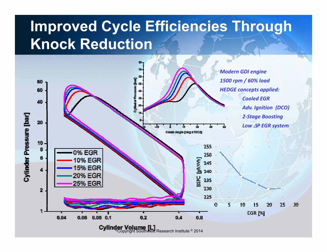
Improved Cycle Efficiencies Through Knock ReductionKnock Reduction
Modern GDI engine/1500 rpm / 60% load
HEDGE concepts applied:Cooled EGRAdv. Ignition (DCO)g ( )2‐Stage Boosting
Low P EGR system
©Copyright Southwest Research Institute ® 2014

Emissions Reduction With EGR
/
©Copyright Southwest Research Institute ® 2014
Data from modern GDI application @ 3000 rpm / 75% load

Enabling Technologies for High Dilution ApplicationsDilution Applications
©Copyright Southwest Research Institute ® 2014

Full Map Fuel Economy Improvement with Cooled EGRwith Cooled EGR
22BSFC [g/kWh]
1.6 L GDI Engine25 % EGR
1.6 L GDI Engine (series configuration) Full map improvement =
real world and test cycle
240
260260
14
16
18
20
P [b
ar]
BSFC [g/kWh]
225
20
22BSFC [g/kW-hr]
10.5 : 1 CR real world and test cycle FE improvement
260
230
6
8
10
12
Eng
ine
BMEP
230
225
22014
16
18
P [b
ar]
330300
1500 2000 2500 3000 3500 40002
4
Engine Speed [rpm]
8
10
12
Engi
ne B
MEP
•Typical improvement over GDI
330300
260
2
4
6baseline : 6-9%•Improvement over TC MPI engine (including adding cam phasers) : 8 11%
©Copyright Southwest Research Institute ® 2014
1500 2000 2500 3000 3500 40002
Engine Speed [rpm]
phasers) : 8-11%•Improvement over NA MPI baseline : > 11%
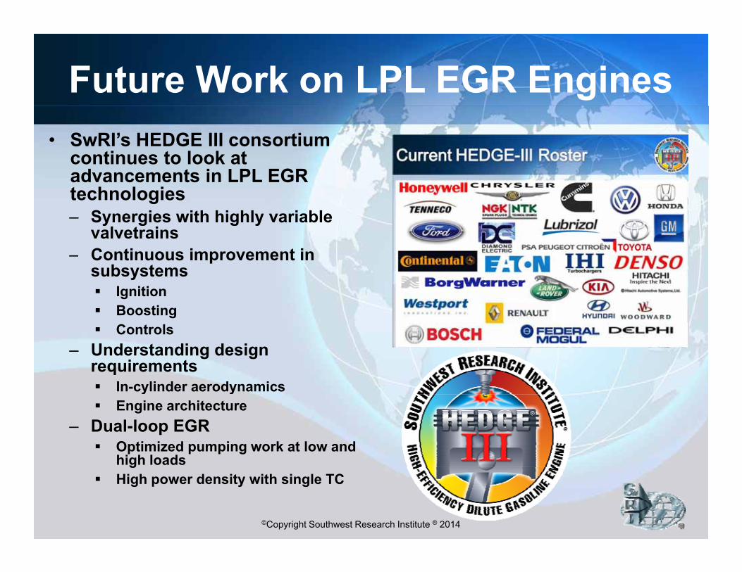
Future Work on LPL EGR Engines• SwRI’s HEDGE III consortium
continues to look at advancements in LPL EGRadvancements in LPL EGR technologies– Synergies with highly variable
valvetrainsC ti i t i– Continuous improvement in subsystems Ignition Boosting Controls
– Understanding design requirements In-cylinder aerodynamics Engine architecture
– Dual-loop EGR Optimized pumping work at low and
high loads
©Copyright Southwest Research Institute ® 2014
g High power density with single TC
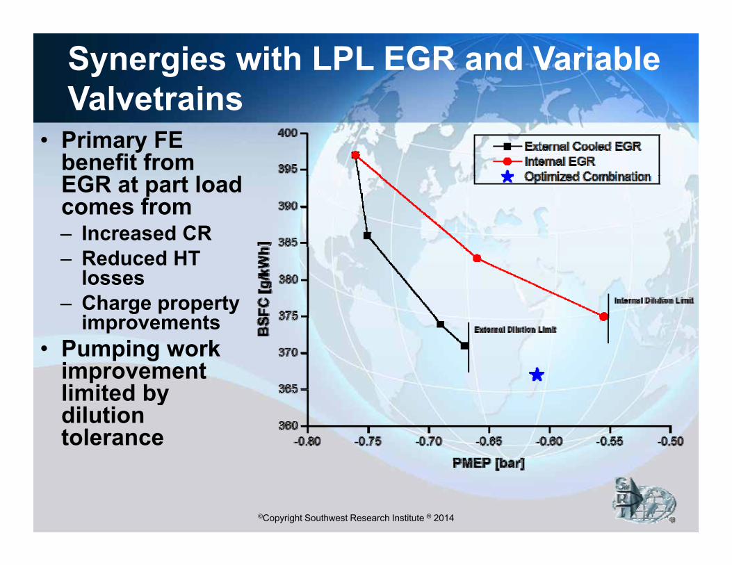
Synergies with LPL EGR and Variable ValvetrainsValvetrains
• Primary FE benefit from EGR l dEGR at part load comes from– Increased CR– Reduced HT
losses – Charge property
i timprovements• Pumping work
improvement limited bylimited by dilution tolerance
©Copyright Southwest Research Institute ® 2014

Blended EGR*Dual-loop EGR for Pumping Work OptimizationDual loop EGR for Pumping Work Optimization
• HPL EGRAt low load– At low load
– At high speed / high load• LPL EGR
4000 RPM4000 RPMBlended EGRBlended EGR
4000 RPM4000 RPMBlended EGRBlended EGR
6000 RPM6000 RPMHPL EGRHPL EGR6000 RPM6000 RPMHPL EGRHPL EGR LPL EGR
– At low speed / high load2000 RPM2000 RPMLPL EGRLPL EGR
2000 RPM2000 RPMLPL EGRLPL EGR
•HPL + LPL EGR− At mid-speed / high load
©Copyright Southwest Research Institute ® 2014*patent pending*patent pending*patent pending*patent pending
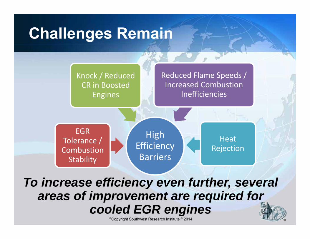
Challenges Remain
Knock / Reduced Reduced Flame Speeds /Knock / Reduced CR in Boosted
Engines
Reduced Flame Speeds / Increased Combustion
Inefficiencies
HighEGR High Efficiency Barriers
Tolerance / Combustion Stability
Heat Rejection
To increase efficiency even further, several areas of improvement are required for
©Copyright Southwest Research Institute ® 2014
areas of improvement are required for cooled EGR engines

Dedicated EGRImproving Efficiency Via In-Cylinder ReformingImproving Efficiency Via In Cylinder Reforming
ɸ > 1.00ɸ > 1.00
ɸ = 1.00ɸ = 1.00
©Copyright Southwest Research Institute ® 2014
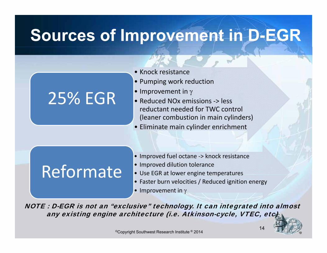
Sources of Improvement in D-EGR
• Knock resistancek d• Pumping work reduction
• Improvement in • Reduced NOx emissions ‐> less reductant needed for TWC control
25% EGRreductant needed for TWC control (leaner combustion in main cylinders)
• Eliminate main cylinder enrichment
• Improved fuel octane ‐> knock resistance• Improved dilution tolerance• Use EGR at lower engine temperaturesReformate Use EGR at lower engine temperatures• Faster burn velocities / Reduced ignition energy• Improvement in
Reformate
NOTE : D-EGR is not an “exclusive” technology It can integrated into almost
©Copyright Southwest Research Institute ® 201414
NOTE : D-EGR is not an exclusive technology. It can integrated into almost any existing engine architecture (i.e. Atkinson-cycle, VTEC, etc)
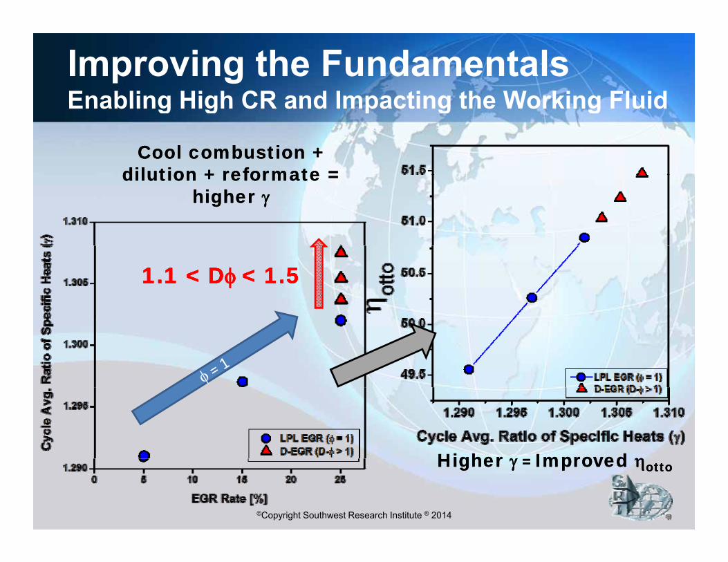
Improving the FundamentalsEnabling High CR and Impacting the Working FluidEnabling High CR and Impacting the Working Fluid
Cool combustion + Cool combustion + dilution + reformate = dilution + reformate = dilution + reformate = dilution + reformate =
higher higher
1.1 < 1.1 < DD < 1.5< 1.51.1 < 1.1 < DD < 1.5< 1.5
Higher Higher Improved Improved
©Copyright Southwest Research Institute ® 2014
Higher Higher = = Improved Improved ottootto
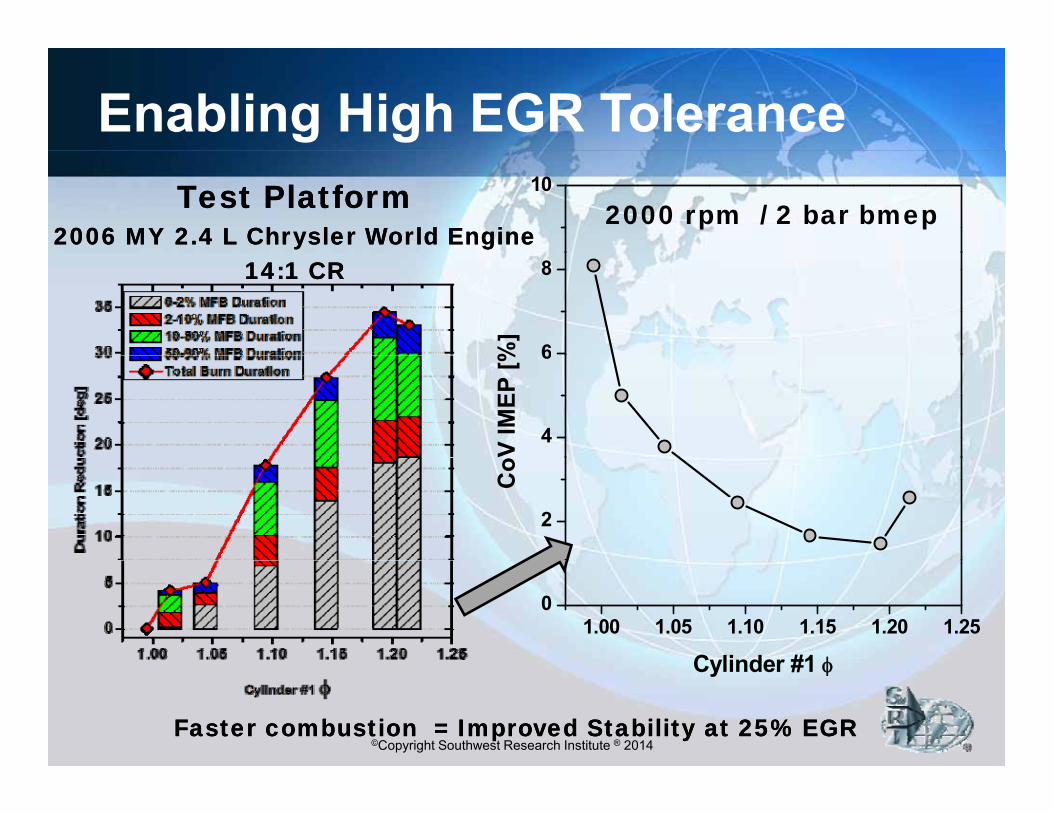
Enabling High EGR Tolerance10
2000 rpm / 2 bar bmepTest PlatformTest Platform2006 MY 2.4 L Chrysler World Engine2006 MY 2.4 L Chrysler World Engine
6
8
%]
14:114:1 CRCR
4
6
V IM
EP [%
2C
o
1.00 1.05 1.10 1.15 1.20 1.250
Cylinder #1
©Copyright Southwest Research Institute ® 2014
Cylinder #1
Faster combustion = Improved Stability at 25% EGRFaster combustion = Improved Stability at 25% EGR

Increased Knock Resistance
190
[N-m
] 20002000 RPM WOTRPM WOT
170
180
ak T
orqu
e
160
170
imite
d Pe
a
ReformateReformate Impact on Impact on Effective RONEffective RON
++150
160
Kno
ck L
©Copyright Southwest Research Institute ® 2014
Faster Burn Rates =Faster Burn Rates =ImprovedImproved Knock ToleranceKnock Tolerance
1.00 1.05 1.10 1.15 1.20150
Dedicated Cylinder

Improved Torque at High Compression RatiosRatios
260
2.0 L TC MPI engine2000 RPM
12.6 %
3.3 % EGR
240
250
26012.5:1 CR
25.8 % EGR
25 2 % 24.3 %
20%
220
230
240
[g/kW‐hr]
25.2 %
200
210
220
BSFC
LPL 12.5:1 CR
190
200
6 7 8 9 10 11 12 13 14 15 16 17 18 19
[b ]
D‐EGR 12.5:1 CR
©Copyright Southwest Research Institute ® 2014
Enables High-Efficiency DownsizingBMEP [bar]
18
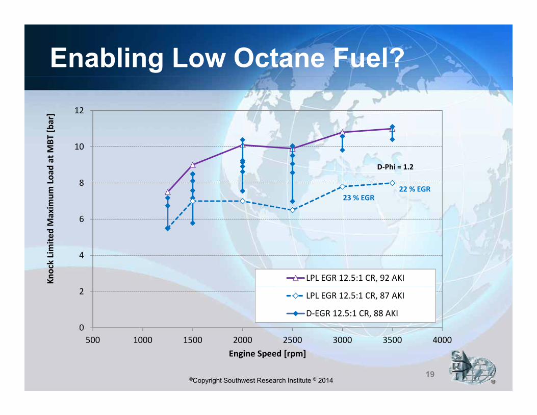
Enabling Low Octane Fuel?12
bar]
D‐Phi = 1.2
8
10
Load
at M
BT [
23 % EGR22 % EGR
6
8
d Maxim
um L
4
Knock Limite
LPL EGR 12.5:1 CR, 92 AKI
0
2
500 1000 1500 2000 2500 3000 3500 4000
LPL EGR 12.5:1 CR, 87 AKI
D‐EGR 12.5:1 CR, 88 AKI
©Copyright Southwest Research Institute ® 2014
500 1000 1500 2000 2500 3000 3500 4000Engine Speed [rpm]
19

Reduced Emissions• Combustion
efficiency returns BSHC
4.5
18
BSCO
4 0
BSNOx
0 27
Soot Mass yto nearly non-dilute levels
• Reformate 3 0
3.5
4.0
4.5
14
16
18
3.0
3.5
4.0
0 24
0.25
0.26
0.27
Simproves HC and CO emissions
• NOx emissions2.0
2.5
3.0
HC
[g/k
W-h
r]
8
10
12
SC
O [g
/kW
-hr]
1 5
2.0
2.5
NO
x [g
/kW
-hr]
0 21
0.22
0.23
0.24 oot Mass [m
g/ NOx emissions increase slightly– Still ~ ¼ of non-
dilute case0.5
1.0
1.5 BS
H
2
4
6BS
0.5
1.0
1.5
BS
N
0.19
0.20
0.21
/kW-hr]
dilute case• Significant PM
reduction enabledEngine‐out Emissions:
1.05 1.10 1.15 1.20 1.25 1.30
D-EGR Equivalence Ratio [-]
0.00 0.00.18
©Copyright Southwest Research Institute ® 2014
enabledg2.0 L TC MPI D‐EGR Engine2000 rpm 10.5 bar BMEP
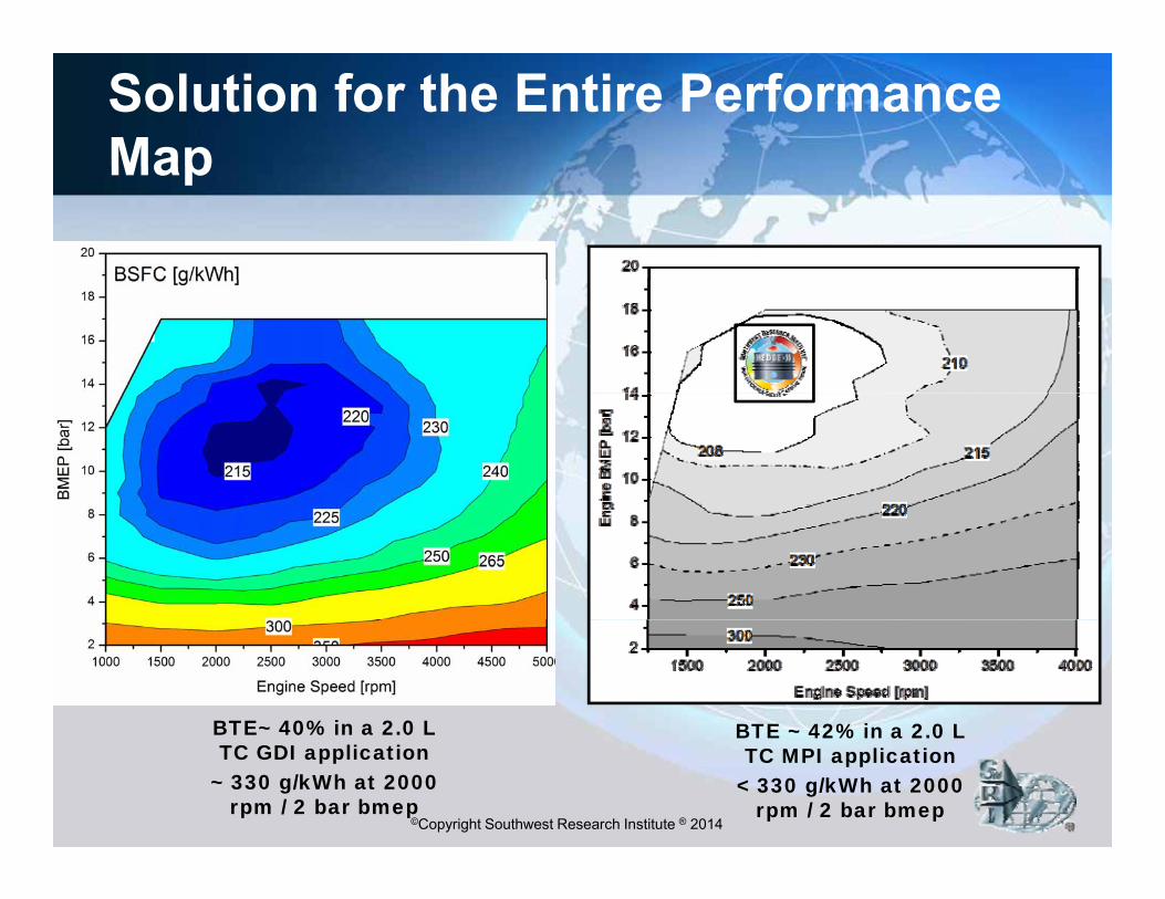
Solution for the Entire Performance MapMap
BTE~ 40% in a 2.0 L BTE ~ 42% in a 2 0 L
©Copyright Southwest Research Institute ® 2014
BTE 40% in a 2.0 L TC GDI application
~ 330 g/kWh at 2000 rpm / 2 bar bmep
BTE 42% in a 2.0 L TC MPI application
< 330 g/kWh at 2000 rpm / 2 bar bmep
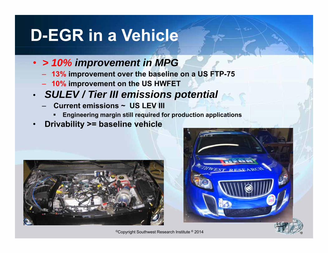
D-EGR in a Vehicle• > 10% improvement in MPG
– 13% improvement over the baseline on a US FTP-75– 10% improvement on the US HWFET
• SULEV / Tier III emissions potential– Current emissions ~ US LEV III
Engineering margin still required for production applications• Drivability >= baseline vehicle
©Copyright Southwest Research Institute ® 2014
Summary
• The use of EGR – cooled LPL or H2 enriched D EGR h i ifi t ffi i b fitD-EGR – has significant efficiency benefits– Reduced knock → high CR downsizing
I d h ti– Improved charge properties– Reduced emissions and exhaust temperatures
Improved combustion phasing– Improved combustion phasing• Success demonstrated via early work in LPL
EGR leads to new research directionsEGR leads to new research directions– D-EGR
EGR + VVA
©Copyright Southwest Research Institute ® 2014
– EGR + VVA– Advanced enabling technologies
Contact InformationContact InformationDr. Terry AlgerDr. Terry Alger
Contact InformationContact InformationDr. Terry AlgerDr. Terry AlgerDr. Terry AlgerDr. Terry [email protected]@swri.org
(m) 210(m) 210--248248--64336433(w) 210(w) 210 522522 55055505
Dr. Terry AlgerDr. Terry [email protected]@swri.org
(m) 210(m) 210--248248--64336433(w) 210(w) 210 522522 55055505(w) 210(w) 210--522522--55055505(w) 210(w) 210--522522--55055505
Southwest Research Institute®
©Copyright Southwest Research Institute ® 201424