quicksilver, rideguide and mmpp. gasoline engine · pdf filequicksilver, rideguide and mmpp....
TRANSCRIPT
90-860175010 SEPTEMBER 2001 Printed in U.S.A. - 2001, Mercury Marine Page 1 of 78
The following are registered trademarks ofBrunswick Corporation: Merc, MerCathode,MerCruiser, Mercury, Mercury Marine,Quicksilver, RideGuide and MMPP.
GASOLINE ENGINE INBOARD AND TOWSPORT MODELS INSTALLATION MANUAL
Models Covered
Inboard
Model Serial Number or Year
5.7L 0L677946 and Above
Tow Sport
Model Serial Number or Year
5.7L
Black Scorpion 0L678016 and Above
MX 6.2L MPI Black Scorpion
Notice
NOTICE
After completing installation, these instructions should be placed with theproduct for the owner’s future use.
NOTICE
Predelivery preparation instructions must be performed before delivering boatto the product owner.

GASOLINE ENGINE INBOARD MODELS
Page 2 of 78 90-860175010
Table of Contents
General Information 3. . . . . . . . . . . . . . . . . . . . Notice to Boat Manufacturer/Installer 3. . . .
Torque Specifications 4. . . . . . . . . . . . . . . . . . Lubricants / Sealants / Adhesives 4. . . . . . . Quicksilver Products 4. . . . . . . . . . . . . . . . . . .
Accessories 4. . . . . . . . . . . . . . . . . . . . . . . . . . Serial Number Decal Placement 5. . . . . . . . . Engine Rotation 5. . . . . . . . . . . . . . . . . . . . . . . . Transmissions 5. . . . . . . . . . . . . . . . . . . . . . . . .
Velvet Drive Transmissions 5. . . . . . . . . . . . ZF / Hurth Transmissions 6. . . . . . . . . . . . . . Propeller Rotation 8. . . . . . . . . . . . . . . . . . . .
Boat Construction 10. . . . . . . . . . . . . . . . . . . . . . Engine Bed 10. . . . . . . . . . . . . . . . . . . . . . . . . .
Seawater Connections 11. . . . . . . . . . . . . . . . . . Seawater Pickups 11. . . . . . . . . . . . . . . . . . . .
Preliminary Connections 13. . . . . . . . . . . . . . . Fuel Inlet Fitting 13. . . . . . . . . . . . . . . . . . . . . . Coolant Recovery System Connections 14. .
Engine Mount Pre-Adjustment 15. . . . . . . . . . Engine Preparation 17. . . . . . . . . . . . . . . . . . . . .
Engine Oil Dipstick Relocation 18. . . . . . . . . . Engine Installation and Initial Engine Alignment 18. . . . . . . . . . . . . . . . . . . . . . . . . . . .
Models With 8 Degree Down Angle Transmissions - Velvet Drive or Hurth 18. . Models with V-Drive Transmissions 20. . . . . All Models, If Equipped 21. . . . . . . . . . . . . . . . Hot Water Heater Installation Information 21
Exhaust System 24. . . . . . . . . . . . . . . . . . . . . . . . Measuring Procedures 24. . . . . . . . . . . . . . . . Measurement Methods 27. . . . . . . . . . . . . . . . Exhaust System Hose / Tube Connections 30
Electrical Connections 31. . . . . . . . . . . . . . . . . Instrumentation Connections 31. . . . . . . . . . . Audio Warning System Connection 32. . . . .
Fluid Connections 33. . . . . . . . . . . . . . . . . . . . . . Coolant Recovery Bottle 33. . . . . . . . . . . . . . .
Final Engine Alignment 33. . . . . . . . . . . . . . . . . Engine Connections 39. . . . . . . . . . . . . . . . . . . .
Seawater Pickup Pump Connection 39. . . . . Throttle Cable Installation and Adjustment 40. . . . . . . . . . . . . . . . . . . . . . . . . . .
Carbureted Models 40. . . . . . . . . . . . . . . . . . . Black Scorpion Models 41. . . . . . . . . . . . . . . .
Shift Cable Installation And Adjustment 42. Velvet Drive Transmissions 42. . . . . . . . . . . . Hurth Transmissions 50. . . . . . . . . . . . . . . . . .
Predelivery Preparation 55. . . . . . . . . . . . . . . . . Propeller Selection 55. . . . . . . . . . . . . . . . . . . . Engine Rev-Limiter 56. . . . . . . . . . . . . . . . . . . Fuel Line Connection 56. . . . . . . . . . . . . . . . . . Battery 56. . . . . . . . . . . . . . . . . . . . . . . . . . . . . . Test Running Engine 58. . . . . . . . . . . . . . . . . . Boat-In-The-Water Tests 59. . . . . . . . . . . . . . . Cold Weather and Extended Storage DrainingInstructions 61. . . . . . . . . . . . . . . . . . . . . . . . . . Closed Cooled (Coolant) Models 65. . . . . . . .
Wiring Diagrams 68. . . . . . . . . . . . . . . . . . . . . . . Instrumentation 68. . . . . . . . . . . . . . . . . . . . . . . MIE 5.7L Inboard Engines 70. . . . . . . . . . . . . MIE Black Scorpion Models -Starting and Charging System Harness 72. . . . . . . . MIE Black Scorpion Models - Fuel and Ignition System Harness 74. . . . . . . . . . . . . .
MIE Water Flow Diagrams 75. . . . . . . . . . . . . . . Gasoline Engines with Seawater Cooling System 75. . . . . . . . . . . . . . . . . . . . . Gasoline Engines with Closed Cooling System 76. . . . . . . . . . . . . . . . . . . . . . . . . . . . .
Predelivery Inspection 78. . . . . . . . . . . . . . . . . .
GASOLINE ENGINE INBOARD MODELS
90-860175010 Page 3 of 78
General Information
Notice to Boat Manufacturer/InstallerThroughout this publication, Warnings and Cautions (accompanied by the InternationalHazard Symbol ! ) are used to alert the manufacturer or installer to special instructionsconcerning a particular service or operation that may be hazardous if performed incorrectlyor carelessly. –– Observe Them Carefully!
These Safety Alerts, alone, cannot eliminate the hazards that they signal. Strict complianceto these special instructions when performing the service, plus common sense operation,are major accident prevention measures.
WARNINGHazards or unsafe practices which could result in severe personal injury or death.
CAUTIONHazards or unsafe practices which could result in minor personal injury or productor property damage.
IMPORTANT: Indicates information or instructions that are necessary for properinstallation and/or operation.
NOTE: Refer to the Mercury MerCruiser Product Applications Manual - Gasoline SterndriveModels for application recommendations.
This installation manual has been written and published by Mercury Marine to aid the boatmanufacturer (OEM) in the installation of the products described herein.
It is assumed that these personnel are familiar with marine product installation.Furthermore, it is assumed that they are familiar with, if not trained in, the recommendedinstallation procedures of Mercury MerCruiser product.
We could not possibly know of or advise the marine trade of all conceivable installations andof the possible hazards and/or results of each installation. Therefore, the OEM isresponsible for any installation that does not fulfil the requirements of this manual.
It is the responsibility of the boat manufacturer to select the appropriateengine/transom/drive package (including the correct gear ratio and propeller) for a givenboat. Mercury recommends that any new or unique hull/power package combination bethoroughly water tested prior to sale, to verify that the boat performs as desired, and thatthe engine runs in the appropriate rpm range.
It is recommended that a Mercury Marine Sales Application Engineer (SAE) be contactedfor assistance.
All information, illustrations and specifications contained in this manual are based on thelatest product information available at time of publication. As required, revisions to thismanual will be sent to all OEM boat companies.

GASOLINE ENGINE INBOARD MODELS
Page 4 of 78 90-860175010
Torque SpecificationsNOTE: Securely tighten all fasteners not listed below.
Description Nm lb-in. lb-ft
Engine Mount Bracket Screws 64 47
Trunnion Clamping Bolt and Nut 68 50
Propeller Shaft Nut 68 50
Exhaust Manifold Screw 27 20
Fuel Line Inlet FittingFinger tight + 1-3/4 to
2-1/4 turns with a wrench.DO NOT overtighten.
Coupler Bolts 68 50
Lubricants / Sealants / Adhesives
Description Where Used Part Number
Silicon Sealant or Equivalent Screw Shaft Obtain Locally
Marine Caulking Seawater Inlet MountingSurfaces
Obtain Locally
Loctite 271 Seawater Inlet Nut 92-809820
Fuel Inlet Fitting
Loctite 592 Seawater Inlet Hose Fitting Obtain Locally
Seawater Inlet Plastic Plug
2 4 C Marine Lubricant with Tef-lon
Shift Cable End 92-825407A3
Special Lube 101 Steering Cable End 92-13872A1
Liquid Neoprene Battery Terminals 92-25711-2
SAE 30W Engine Oil Shift Cable Pivot Points Obtain Locally
Quicksilver ProductsAccessories
Quicksilver gauges, remote controls, steering systems, propellers and other accessoriesare available for this product. Mercury MerCruiser recommends the use of Quicksilver partson all applications. Refer to Mercury Precision Parts / Quicksilver Accessories Guide for acomplete listing.
This Guide is available from:
Mercury MarineAttn: Parts Department
W6250 W. Pioneer RoadP.O. Box 1939
Fond du Lac, WI 54936-1939
Outside of U.S.A., order through Distribution Center or Distributor.

GASOLINE ENGINE INBOARD MODELS
90-860175010 Page 5 of 78
Serial Number Decal Placement
There are three engine serial number decal strips provided with each power package. Oneshould be used for each of the following:
• Engine Specification Decal
• Warranty Registration Card
• Operation, Maintenance and Warranty Manual identification page.
Affix engine serial number decal to Engine Specification Decal.
Engine Rotation
Engine rotation is described when observed from the rear of the engine (transmission end)looking forward (water pump end).
Engine rotation is indicated on engine specifications and serial number decal.
Transmissions
Velvet Drive TransmissionsOn Velvet Drive In-Line and V-Drive Transmissions (71C, 72C, 72C V-Drive, with or withoutWalter transmissions) the gear ratio (in forward gear) is marked on transmissionidentification plate. Transmission output shaft rotation and propeller rotation required (inforward gear) is indicated on a decal on transmission case. Transmission rotation isdescribed when viewed from the rear of transmission.
22556
a
b
c
In-Line Transmission Shown (Others Similarly Located)a - Transmission Identification Plateb - Gear Ratio (In Forward Gear)c - Output Flange Rotation Decal (In Forward Gear)
GASOLINE ENGINE INBOARD MODELS
Page 6 of 78 90-860175010
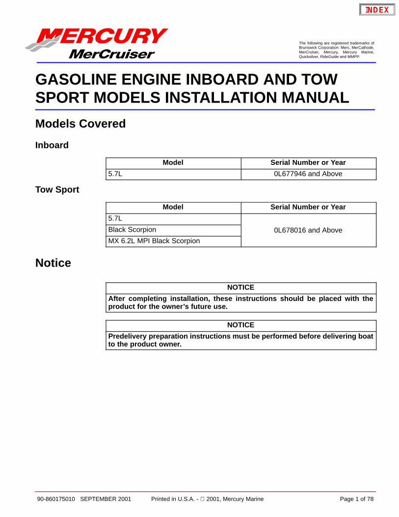
On the Velvet Drive 5000A and 5000V Transmissions the transmission identification plateindicates gear ratio, serial number and model.
71778
a
Velvet Drive 5000A - 8 Degree Down-Angle Transmission Shown (5000V - V-DriveSimilar)
a - Transmission Identification Plate
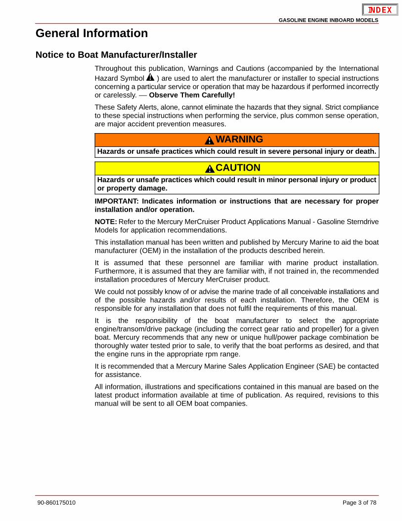
ZF / Hurth TransmissionsOn the Hurth 8 Degree Down-Angle and V-Drive Transmissions the transmissionidentification plate indicates gear ratio, serial number and model.
73587
a
Typical Hurth Down-Angle Transmission Shown (V-Drive Identification PlateSimilarly Located)
a - Transmission Identification Plate

GASOLINE ENGINE INBOARD MODELS
90-860175010 Page 7 of 78
WALTER V-DRIVE TRANSMISSIONS
On the Walter V-Drive Transmissions the transmission identification plate indicates gearratio, serial number and model.
75195
a
Walter RV-36 V-Drivea - Transmission Identification Plate

GASOLINE ENGINE INBOARD MODELS
Page 8 of 78 90-860175010
Propeller RotationPropeller rotation is not necessarily the same as engine rotation. Refer to the appropriatefollowing information and drawings for specific information.
These transmissions are full power reversing transmissions, allowing a standard (LHrotation) engine to be used for both propeller rotations. Propeller rotation (output shaftrotation) is determined by shift cable attachment at the remote control. Be sure to usecorrect rotation propeller and shift cable hook up for direction desired.
a
b
c
b71888
d
e
Velvet Drive 5000A - 8 Degree Down-Angle Transmission
a
b
f
74604
b
g
d
Velvet Drive 5000V - V-Drive Transmissionsa - Direction of Shift Lever Engagement (Toward Flywheel)b - Engine/Transmission Input Shaft Rotation Direction (LH)c - Transmission Output/Propeller Shaft Rotation Direction (LH)d - Direction of Shift Lever Engagement (Away From Flywheel)e - Transmission Output/Propeller Shaft Rotation Direction (RH)f - Transmission Output/Propeller Shaft Rotation Direction (LH as viewed at
propeller)g - Transmission Output/Propeller Shaft Rotation Direction (RH as viewed at the
propeller)
GASOLINE ENGINE INBOARD MODELS
90-860175010 Page 9 of 78
Propeller Rotation (Continued)
c
25506
a
b
d
e
b
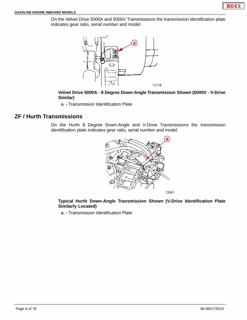
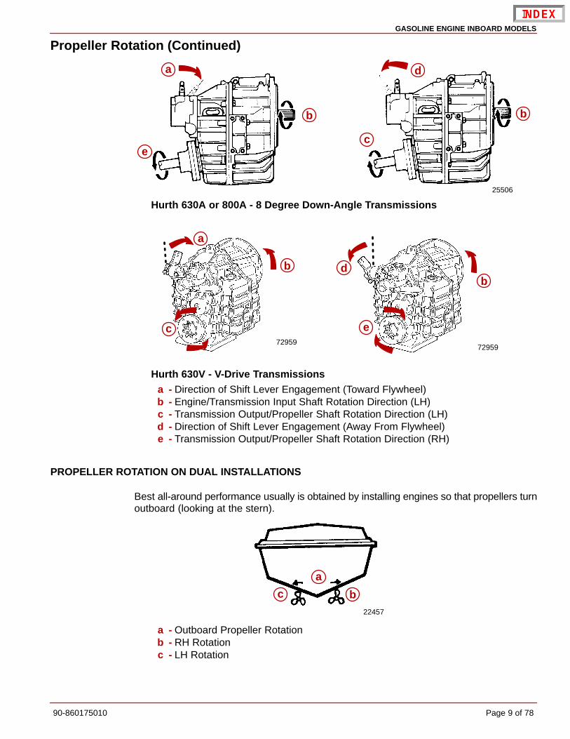
Hurth 630A or 800A - 8 Degree Down-Angle Transmissions
7295972959
a
b
c
d
e
b
Hurth 630V - V-Drive Transmissionsa - Direction of Shift Lever Engagement (Toward Flywheel)b - Engine/Transmission Input Shaft Rotation Direction (LH)c - Transmission Output/Propeller Shaft Rotation Direction (LH)d - Direction of Shift Lever Engagement (Away From Flywheel)e - Transmission Output/Propeller Shaft Rotation Direction (RH)
PROPELLER ROTATION ON DUAL INSTALLATIONS
Best all-around performance usually is obtained by installing engines so that propellers turnoutboard (looking at the stern).
22457
a
c b
a - Outboard Propeller Rotationb - RH Rotationc - LH Rotation
GASOLINE ENGINE INBOARD MODELS
Page 10 of 78 90-860175010
APPLICATION / RATIO SELECTION
The propeller shaft speed is determined by engine speed and the transmission ratio. Everyboat has a most desirable shaft speed which has a direct relationship to boat speed. If shaftspeeds are too high an inordinately small propeller must be used which will result in poorperformance. If they are too low then too large a prop must be used. Fast boats do best withdirect drive or small reductions. Heavier and slower boats require corresponding greaterratios of reduction. 100 rpm of prop shaft speed for each MPH of boat speed is a rough ruleof thumb for selecting the drive ratio.
COUPLING
The coupling is a flange type coupler (available through Quicksilver Accessories). Allcoupler bolts must be SAE Grade 8 (Metric Grade 10.9) or better, with a shoulder (griplength) long enough to pass through the face mating plane of couplers. All coupler boltsmust be torqued to 50 lb-ft (68 Nm).
ENGINE/PROPELLER SHAFT INSTALLATION ANGLE
The transmission and engine should be mounted so that the angle relative to horizontal isas shown in the installation drawings. Refer to individual installation drawings for eachspecific engine and transmission.
IMPORTANT: Relative to horizontal, never install the engine with the front (pulleyend) down.
IMPORTANT: On all engines, a high angle of installation [front (pulley end) of engineup] along with low transmission oil levels can permit transmission pump cavitationon some models when operating in rough water.
PROPELLER SHAFT DIAMETER
Propeller shaft diameter should be of sufficient size for the type of application.
VELVET DRIVE IN-LINE AND V-DRIVE TRANSMISSIONS (EXCEPT 5000 SERIES)
IMPORTANT: Velvet Drive In-Line and V-Drive Transmissions Only – Use of properrotation propeller (specified on transmission output flange rotation decal) is criticalsince the transmission must be operated in forward gear selector position only todrive boat forward. If the wrong rotation propeller is installed and transmission isoperated in reverse to propel the boat forward, transmission failure WILL occur.
IMPORTANT: On engines which are equipped with Velvet Drive In-line transmissions,a LH propeller is required.
Boat Construction
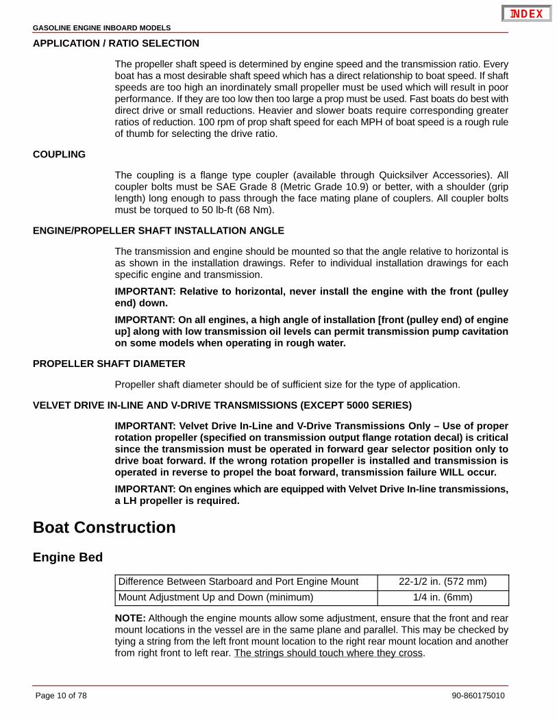
Engine Bed
Difference Between Starboard and Port Engine Mount 22-1/2 in. (572 mm)
Mount Adjustment Up and Down (minimum) 1/4 in. (6mm)
NOTE: Although the engine mounts allow some adjustment, ensure that the front and rearmount locations in the vessel are in the same plane and parallel. This may be checked bytying a string from the left front mount location to the right rear mount location and anotherfrom right front to left rear. The strings should touch where they cross.

GASOLINE ENGINE INBOARD MODELS
90-860175010 Page 11 of 78
Seawater Connections
Seawater PickupIMPORTANT: Seal the edges of any hole made through the hull with a suitable sealantto prevent water absorption and deterioration.
THROUGH THE HULL MOUNTED
1. Seal the inside edges of the 1-3/4 in. (44 mm) hole in the hull using a suitable sealer.
2. Apply marine caulking (sealer) to mounting surface on seawater pickup where hullcontact will occur when installed.
Description Where Used Part Number
A Marine Caulking Mounting Surfaces Obtain Locally
IMPORTANT: Seawater inlet slots must face forward - parallel with the flow of water.
3. Ensure slots in seawater pickup are facing forward (toward bow of boat) and installseawater pickup through hull.
4. Fasten pickup with four appropriate mounting screws (if so designed).
5. Apply marine caulking as needed inside boat. Apply sealant to the threads of the nut andinstall on the pickup on the inside of the boat and torque the nut.
72639a
b
c
d
A
a - Seawater Pickupb - Seawater Inlet Slotsc - Mounting Screw Holes (If Equipped)d - Nut
Description Where Used Part Number
A Loctite 271 Seawater Pickup Nut 92-809820
Description Nm lb-in. lb-ft
Nut 42 35
NOTE: If pickup being installed does not have mounting screws on underside wheremounted to hull, be certain, after nut is torqued, that slots are still facing forward.

GASOLINE ENGINE INBOARD MODELS
Page 12 of 78 90-860175010
Transom Mounted
72640
ab
c
de
f
g h
ij
A
A
a - Hose Fittingb - Nut (4)c - Gasketd - O-ring (4)e - Washer (4)f - Screw (4)g - Plastic Pugh - Pickupi - Screenj - Screw (2)
1. Seal the inside edges of the 1-1/2 in. (38 mm) hole hose fitting.
2. Be certain hose fitting and plastic plug are in place and threads have been sealed withLoctite Pipe Sealant with Teflon prior to tightening each securely.
Description Where Used Part Number
Hose Fitting ThreadsA Loctite 592 PST
Plastic Plug ThreadsObtain Locally
B Silicon Sealant or Equivalent Screw Shaft Obtain Locally
NOTE: Use a sharp knife or wood chisel to remove excess plastic plug material so that plugis flush with pickup casting.
3. Position one flat washer and one rubber O-ring on each 5/16 in. x 4 in. (102 mm) long,round head screw as shown. Coat each screw shaft with silicone sealant or equivalent.
4. Place new gasket on pickup housing and hold pickup in place on transom. Install fourround head screws (with washers and O-rings in place) into pickup mounting holes andthrough drilled 21/64 in. (8 mm) holes in transom.
5. Secure water pickup from inside with locknuts and washers (unless using lag bolts).
6. Tighten fasteners securely.

GASOLINE ENGINE INBOARD MODELS
90-860175010 Page 13 of 78
Preliminary Connections
Fuel Inlet FittingIMPORTANT: The following information is provided to ensure proper installation ofbrass fittings or plugs installed into fuel pump or fuel filter base:
• Use #592 Loctite Pipe Sealant with Teflon on threads of brass fittings or plugs. DONOT USE TEFLON TAPE.
WARNINGBoating standards (NMMA, ABYC and others) and Coast Guard regulations mustbe adhered to when installing fuel delivery system.
WARNINGAvoid gasoline fire or explosion. Improper installation of brass fittings or plugs intofuel pump or fuel filter base can crack casting and/or cause a fuel leak.
1. Remove plastic plug from fuel inlet hole.
2. Apply sealant to threads of fuel inlet fitting. DO NOT USE TEFLON TAPE.
WARNINGOvertightening the fuel inlet fitting can lead to fuel leaks, avoid severe personalinjury or death from a gasoline fire or explosion. DO NOT use a power tool (i.e.impact wrench) to tighten the fuel inlet fitting.
3. Install fuel fitting. To prevent cracking the casting or causing fuel leaks, turn inletconnector in by hand until finger tight, then tighten connector to 1-3/4 to 2-1/4 turns withwrench. DO NOT overtighten.
77950
a A
Typical Fittingsa - Fuel Inlet Hose Fitting Location
Description Where Used Part Number
A Loctite 592 Fuel Inlet Fitting Obtain Locally
Description lb-ft lb-in. Nm
Fuel Line Inlet FittingFinger tight + 1-3/4 to
2-1/4 turns with a wrench.DO NOT overtighten.

GASOLINE ENGINE INBOARD MODELS
Page 14 of 78 90-860175010
SPECIAL INFORMATION ABOUT ELECTRIC FUEL PUMPS
CAUTIONThe electric fuel pump and factory installed water separating fuel filter have beencarefully designed to function properly together. Do not install additional fuel filtersand/or water separating fuel filters between fuel tank and engine.
The installation of additional filters may cause:
• Fuel Vapor Locking
• Difficult Warm-Starting
• Piston Detonation Due to Lean Fuel Mixture
• Poor Driveability
Coolant Recovery System Connections1. Select a mounting location for coolant recovery bottle and mounting bracket that meets
all of the following:
a. Within limits of clear plastic tubing.
b. Level with or above the heat exchanger fill neck.
c. Accessible for observing coolant level and filling.
2. Mount coolant recovery bottle and mounting bracket in desired location, using two3/4 in. (19 mm) long screws and flat washers.
3. Route plastic tubing to recovery bottle. Ensure that tubing is positioned away from anymoving parts. Cut plastic tubing as required and connect to bottom connection onrecovery bottle and secure with tubing clamp provided.
4. Fasten plastic tubing to boat as necessary, with the 2 hose clips and 1/2 in. (13 mm) longscrews provided.
71712
a
b
c
da - Recovery Bottle And Mounting Bracketb - Screws And Flat Washersc - Plastic Tubingd - Tubing Clamp
GASOLINE ENGINE INBOARD MODELS
90-860175010 Page 15 of 78
Engine Mount Pre-Adjustment
1. Remove hardware holding engine to shipping pallet. Attach a suitable sling to lifting eyeson engine. Lift engine from pallet with an overhead hoist.
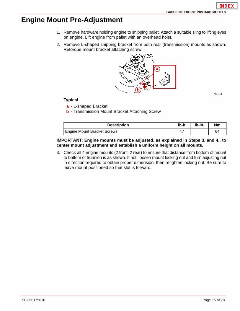
2. Remove L-shaped shipping bracket from both rear (transmission) mounts as shown.Retorque mount bracket attaching screw.
74623
a
b
Typicala - L-shaped Bracketb - Transmission Mount Bracket Attaching Screw
Description lb-ft lb-in. Nm
Engine Mount Bracket Screws 47 64
IMPORTANT: Engine mounts must be adjusted, as explained in Steps 3. and 4., tocenter mount adjustment and establish a uniform height on all mounts.
3. Check all 4 engine mounts (2 front, 2 rear) to ensure that distance from bottom of mountto bottom of trunnion is as shown. If not, loosen mount locking nut and turn adjusting nutin direction required to obtain proper dimension, then retighten locking nut. Be sure toleave mount positioned so that slot is forward.

GASOLINE ENGINE INBOARD MODELS
Page 16 of 78 90-860175010
4. Loosen clamping bolts and nuts on all 4 engine mount brackets to ensure the following:
• Large diameter of mount trunnion extended.
• Mount base slotted mounting hole forward, if so designed.
• Each mount base is downward. Tighten clamping bolts and nuts slightly to preventmoving in or out. Mounts must be free to pivot when installing engine.
70140 70158
a
e
d
fb
cga
b
ce
f
g
Front Mount Typical Rear Mounta - Locking Nutb - Adjusting Nutc - Trunnion Clamp Screws And Nuts, With Lockwashersd - Slot Forwarde - 3/8 in. + 1/16 in. (10mm + 2mm)f - 2-5/8 in. + 1/16 in. (67mm + 2mm)g - Mount Trunnion
GASOLINE ENGINE INBOARD MODELS
90-860175010 Page 17 of 78
Engine Preparation
1. Remove and read all tags attached to engine.
2. Remove all hardware that secures engine to shipping container.
3. Connect battery cables to engine. Be sure to observe the following:
a. Ensure that grounding stud and starter solenoid terminal are free of paint or anyother material that could cause a poor electrical connection.
b. After battery cables are connected, apply a thin coat of sealant to the terminals.
Description Where Used Part Number
Liquid Neoprene Battery Terminals 92-25711-2
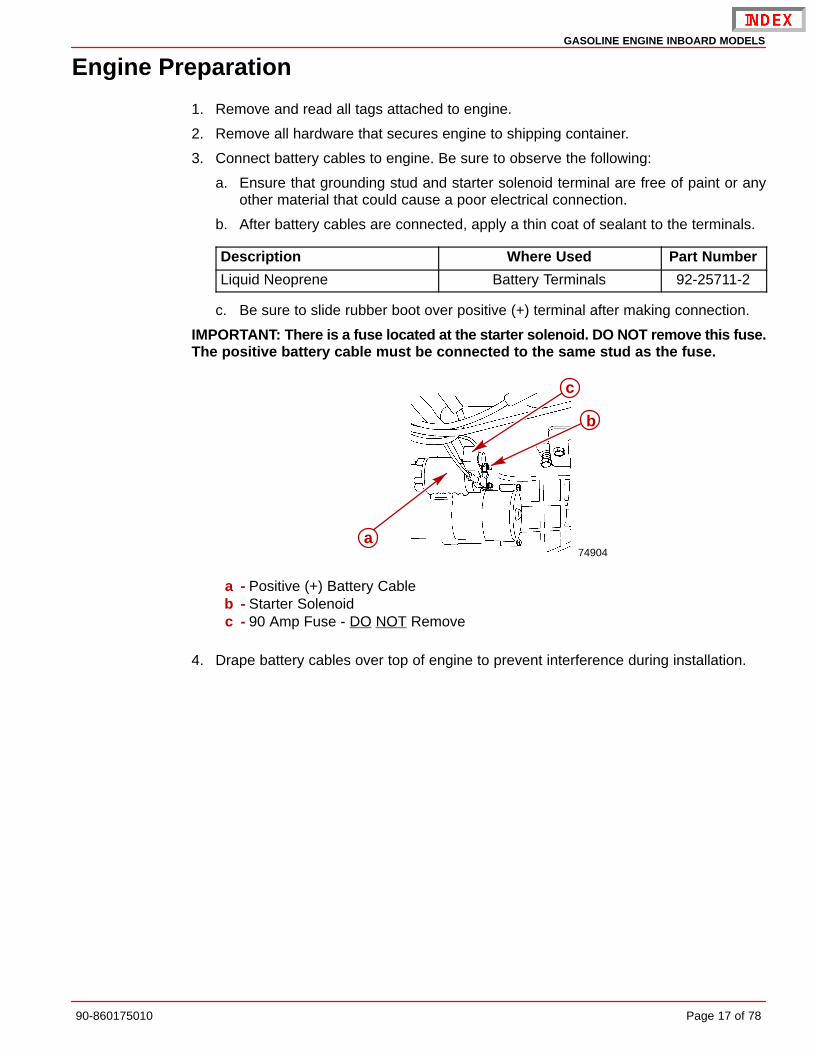
c. Be sure to slide rubber boot over positive (+) terminal after making connection.
IMPORTANT: There is a fuse located at the starter solenoid. DO NOT remove this fuse.The positive battery cable must be connected to the same stud as the fuse.
74904
c
a
b
a - Positive (+) Battery Cableb - Starter Solenoidc - 90 Amp Fuse - DO NOT Remove
4. Drape battery cables over top of engine to prevent interference during installation.

GASOLINE ENGINE INBOARD MODELS
Page 18 of 78 90-860175010
Engine Oil Dipstick Relocation (If Equipped)Engine crankcase oil dipstick can be located on either starboard or port side of engine tosuit installation requirements. To move dipstick, remove dipstick from current location andinstall in opposite side. Place rubber cap over the open dipstick tube.
7638675425
b
a
a - Dipstick (Typical)b - Rubber Cap
Engine Installation and Initial Engine Alignment
Models With 8 Degree Down Angle Transmissions - Velvet Drive or Hurth1. Remove the engine cover.
2. Attach a suitable sling to lifting eyes on engine and adjust so that engine is level whensuspended.
CAUTIONCenter lifting eye on top of thermostat housing is used for engine alignment only.Do not use to lift entire engine.
75532 74510
a
b
a - Rear Lifting Eyeb - Front Lifting Eye

GASOLINE ENGINE INBOARD MODELS
90-860175010 Page 19 of 78
3. Lift engine into position in boat using an overhead hoist.
4. Position engine on engine bed so that transmission output flange and propeller shaftcoupler are visibly aligned (no gap can be seen between coupling faces when buttedtogether). Adjust engine bed height if necessary to obtain proper alignment. DO NOTuse mount adjustments to adjust engine position at this time.
5. Ensure quick drain oil fitting is more than 1/2 in. (6 mm) above the boat bottom.
IMPORTANT: Engine bed must position engine so that a minimum of 1/4 in. (6 mm)up and down adjustment still exists on all 4 mounts after performing initial alignment.This is necessary to allow for final engine alignment.
74546b
c
a
a - Propeller Shaftb - Propeller Shaft Couplerc - Transmission Output Flange
6. Ensure that all 4 mounts are still positioned properly, then fasten mounts to engine bedwith 3/8 in. (10 mm) diameter lag bolts (of sufficient length) and flat washers. Tightenlag bolts securely.
7. Disconnect overhead hoist and remove sling.

GASOLINE ENGINE INBOARD MODELS
Page 20 of 78 90-860175010
Models with V-Drive Transmissions1. Lift engine into position in boat using an overhead hoist.
2. Install quick drain oil hose plug in oil drain hose.
3. Position engine so that enough propeller shaft protrudes through transmission andoutput flange for propeller shaft coupler to be attached. Then install coupler and positionengine (no gap can be seen between coupling faces when butted together). Adjustengine bed height if necessary to obtain proper alignment. DO NOT use mountadjustments to adjust engine position at this time.
IMPORTANT: Engine bed must position engine so that a minimum of 1/4 in. (6 mm)up and down adjustment still exists on all 4 mounts after performing final alignment.This is necessary to allow for final engine alignment.
50608 50608ab
c
d
Hurth 630V (Others Similar)a - Propeller Shaftb - Propeller Shaft Couplerc - Transmission Output Flanged - No Gap Allowed
4. Ensure that all 4 mounts are still positioned properly. Fasten mounts to engine bed with3/8 in. (10 mm) diameter lag bolts (of sufficient length) and flat washers. Tighten lag boltssecurely.
5. Ensure quick drain oil fitting is more than 1/2 in. (6 mm) above the boat bottom.
6. Disconnect overhead hoist and remove sling.

GASOLINE ENGINE INBOARD MODELS
90-860175010 Page 21 of 78
All Models, If Equipped1. Push end of oil drain hose out of boat hull through flange.
2. Pull oil drain hose out until it is 6 in. (152 mm) from the propeller.
3. Move alignment clip on the oil drain hose and squeeze to position it on the hose justinside of the boat hull against the flange.
4. Connect bilge drain plug to oil drain hose plug using clip.
78002
ab
dc
a - Oil Drain Hoseb - Alignment Clipc - Clipd - Bilge Drain Plug
IMPORTANT: If Quick Drain Oil Fitting is within 1/2 in. (6 mm) of boat bottom, removefitting and install drain plug from parts bag directly into oil pan.
5. Push oil drain hose through flange into boat hull.
6. Install bilge drain plug in hull.
Hot Water Heater Installation InformationIMPORTANT: When connecting a cabin heater or hot water heater:
• Supply hose (from engine to heater) and return hose (from heater to engine)MUST NOT EXCEED 5/8 in. (16 mm) I.D. (inside diameter).
• Make heater connections ONLY at locations indicated in the followinginformation.
• Refer to manufacturers’ instructions for complete installation information andprocedures.
• Do not reposition engine temperature switch.
CAUTIONAvoid a performance loss and/or possible engine damage. Engine coolant mustflow continuously from the engine intake manifold to the engine water circulatingpump. NEVER close-off or block the coolant flow to or from a heater.
CAUTIONAvoid engine overheating which could result in engine damage. On modelsequipped with Closed Cooling, an air pocket may form in the closed cooling systemif some coolant is lost from the system and the cabin heater or hot water is mountedhigher than the fill cap on the heat exchanger. Heater must be mounted lower thanthe fill cap of the heat exchanger on models so equipped.

GASOLINE ENGINE INBOARD MODELS
Page 22 of 78 90-860175010
SUPPLY HOSE CONNECTION - ENGINES WITH SEAWATER OR CLOSED COOLING SYSTEM
NOTE: Some models may be equipped with additional fittings.
74973
a
Seawater Cooled Models - If Availablea - Location for Hot Water Supply
71758a
Seawater Cooled Modelsa - Location for Hot Water Supply (Install Bayonet Fitting Here)
75503
a
Closed Cooled Models - If Availablea - Location for Hot Water Supply As Viewed From Top Of Thermostat Housing
(Install Bayonet Fitting Here)

GASOLINE ENGINE INBOARD MODELS
90-860175010 Page 23 of 78
RETURN HOSE CONNECTION - ENGINES WITH SEAWATER OR CLOSED COOLING SYSTEM
75480
a
a - Hot Water Return Hose Connection
76432
a
b
Alternate Connection Fitting - If Availablea - Supply Hose Connectionb - Hot Water Return Hose Connection

GASOLINE ENGINE INBOARD MODELS
Page 24 of 78 90-860175010
Exhaust System
CAUTIONIt is the responsibility of the boat manufacturer or installing dealer to properly lo-cate the engine and install the exhaust system. Improper installation may allow wa-ter to enter the exhaust manifolds and combustion chambers and severely damagethe engine. Damaged caused by the water in the engine will not be covered by Mer-cury MerCruiser Warranty, unless this damage is the result of defective parts.
Measuring Procedure1. Fill all fuel, water, gray water and heater tanks to maximum capacity.
NOTE: Weight can be added in these locations to simulate full loaded condition.
2. Add maximum allowable cargo weight to boat in areas where it will be stowed, includingrefrigerator and lockers.
3. Add 190 lb (86 kg) of weight in all locations where each passenger will sit during normaloperation.
4. Measure exhaust elbow height. Refer to Measurement Methods. Also, measureexhaust system slope on applications with through the hull or through the transomexhaust.
77981
a
b
Using A Universal Protractor (Inclinometer) To Measure Slopea - Protractorb - Exhaust Hose Or Tube
5. Move load weight to bow to simulate greatest bow-down attitude the boat will encounterin normal operation.
6. Recheck exhaust system slope.
7. Move load weight and cargo weight to stern of boat to stimulate greatest stern-downattitude the boat will encounter such as when loading.
IMPORTANT: Be sure to consider swim platform loading and personal watercraft.

GASOLINE ENGINE INBOARD MODELS
90-860175010 Page 25 of 78
8. Recheck exhaust system measurements.
Minimum Exhaust Elbow Height from Top of Elbow to Waterline
Model Measurement
All V6 and V8 13 in. (330 mm)
77956
c
d
b
a
a - Top Of Transomb - Highest Point On Exhaust Elbowc - Measurementd - Waterline
Minimum Continuous Downward Slope (Exhaust Hoses, Collector)
Model Measurement (degrees)
All Sterndrive 6

GASOLINE ENGINE INBOARD MODELS
Page 26 of 78 90-860175010
9. If measurements are less than specified, exhaust elbow risers must be installed toachieve proper dimension.
70621
a
b
c
d
e
Typical Riser Installationa - Exhaust Elbowb - Restrictor Gasketc - Riserd - Open Gasket (4 Slots)e - Exhaust Manifold
NOTE: Up to a maximum of 9 in. (229 mm) of riser height can be added.

GASOLINE ENGINE INBOARD MODELS
90-860175010 Page 27 of 78
Measurement Methods
STRAIGHT EDGE METHOD
1. Place a straight edge across boat.
2. With the straight edge above the engine and parallel to the water, measure the distancesbetween the straight edge and the top of the exhaust elbow.
3. With the straight edge above the engine and parallel to the water measure the distancebetween the straight edge and the outside waterline.
4. The difference between these two measurements is the exhaust elbow height above thewater line. Refer to Measuring Procedure and compare measurement to MercuryMerCruiser’s specifications.
72700
bc
d
ae
76859
a - Waterlineb - Top Of Exhaust Elbowc - Straight Edged - Measurement Between Straight Edge And Top Of Exhaust Elbowe - Measurement Between Straight Edge And Water Line

GASOLINE ENGINE INBOARD MODELS
Page 28 of 78 90-860175010
CLEAR HOSE METHOD
1. Obtain a 5/16 - 3/8 in. (8-10 mm) I.D. hose approximately 15 ft (4.5 m) long. Put a metalfitting or a weight on one end of the hose to keep that end of the hose below the waterline.
2. Put the weighted end of the hose over the port or starboard side of the boat, keepingit in line with the engine’s exhaust elbow.
3. Route the remainder of the hose toward the engine’s exhaust manifold and elbow.Ensure that this open end section of the hose is as vertical as possible from the boat’sbilge to the top of the exhaust elbow
4. Coil excess hose in bilge of boat, keeping it below the water line.
5. Lower open end of hose and siphon water until it starts to come out of the hose. Put afinger over the hose and lift open end until it is at the top of the exhaust elbow.
6. Slowly take finger off end of hose to let the water level stabilize. The water will seek thelevel of the water outside the boat. Keep hose close to exhaust elbow and as verticalas possible.
7. The measurement between water in hose and top of exhaust elbow is the exhaust elbowheight. Ensure that boat is level.
72700
bc
d
a
ea76859
a - Waterlineb - Top Of Exhaust Elbowc - Clear Plastic Hosed - Weighte - Measurement - Waterline To Top Of Exhaust Elbow
Minimum Exhaust Outlet Hose Size
Model Single Outlet Dual Outlet
Inboard
5.7L 4 in. (102 mm) 3 in. (76 mm)
Tow Sports
5.7L
Black Scorpion 3 1/2 (88.9 mm) Not Applicable
MX 6.2L Black Scorpion

GASOLINE ENGINE INBOARD MODELS
90-860175010 Page 29 of 78
NOTE: A kit is available, when applicable, to reduce from the 4 in. (102 mm) to 3 in. (76 mm).Refer to the Mercury Precision Parts / Quicksilver Accessories Guide, for kit part number.
71774
abcd
e
f
Typical Continuously Sloping Exhaust Linea - Exhaust Elbowb - Exhaust Hose Or Pipec - Muffler (If Equipped)d - Exhaust Outlet Internal Shuttere - Exhaust Flapper Valvef - Waterline
71775
ab
c
d
e
f
g
Typical Waterlift Muffler Exhaust Systema - Vent Line [1/4 in. (6 mm)]b - Transomc - Water Lined - Exhaust Hosee - Drain Fittingf - Water Lift Mufflerg - Exhaust Elbow
CAUTIONAvoid severe engine damage. A 1/4 in. (6 mm) vent hose must be run from the high-est point in the seawater system to the exhaust pipe after the water lift muffler tobreak the vacuum and prevent water from back-filling the engine.

GASOLINE ENGINE INBOARD MODELS
Page 30 of 78 90-860175010
Exhaust System Hose / Tube Connections
CAUTIONAvoid exhaust hose failure. Discharge water from exhaust elbow must flow aroundentire inside diameter of hose to avoid causing hot spots which could eventuallyresult in burned-through exhaust hoses. Exhaust hoses and/or tubes must be cor-rectly connected to exhaust elbows so that they do not restrict the flow of dischargewater from exhaust elbow.
1. Exhaust hoses/tubes should be secured at each connection with at least 2 hose clamps.
71653
Correct Connection Incorrect Connection
2. Tighten all exhaust hose and/or exhaust tube clamps securely.
73961
a
a - Hose Clamps
IMPORTANT: S-pipes must be routed under the transmission mounts.
74832
b
a
Tow Sport Modelsa - S-pipeb - Transmission Mount
GASOLINE ENGINE INBOARD MODELS
90-860175010 Page 31 of 78
Electrical Connections
CAUTIONAvoid damage to the EFI electrical system components: Refer to the following pre-cautions when working on or around the EFI electrical harness, or when adding oth-er electrical accessories:
• DO NOT tap accessories into engine harness.
• DO NOT puncture wires for testing (Probing).
• DO NOT reverse battery leads.
• DO NOT splice wires into harness.
• DO NOT attempt diagnostics without proper, approved Service Tools.
IMPORTANT: When routing all wire harnesses and hoses, be sure they are routed andsecured to avoid coming in contact with hot spots on engine and to avoid contactwith moving parts.
Instrumentation ConnectionsWe recommend the use of Quicksilver Instrumentation and Wiring Harnesses which havebeen specifically designed for compatibility with our engines, and to the same high qualityand performance standards. Instrumentation wiring extension harnesses are available inseveral lengths. Refer to Mercury Precision Parts / Quicksilver Accessories Guide forselection.
Refer to Instrumentation Wiring Diagrams for specific wiring diagrams.
CAUTIONIf Quicksilver wiring harness is used and a fused accessory panel is to be installed(40-amp current draw maximum), be sure to connect it as shown in the wiring dia-grams. Do not connect accessory panel at any other location as wires in wiring har-ness may not be of sufficient size to handle current load.
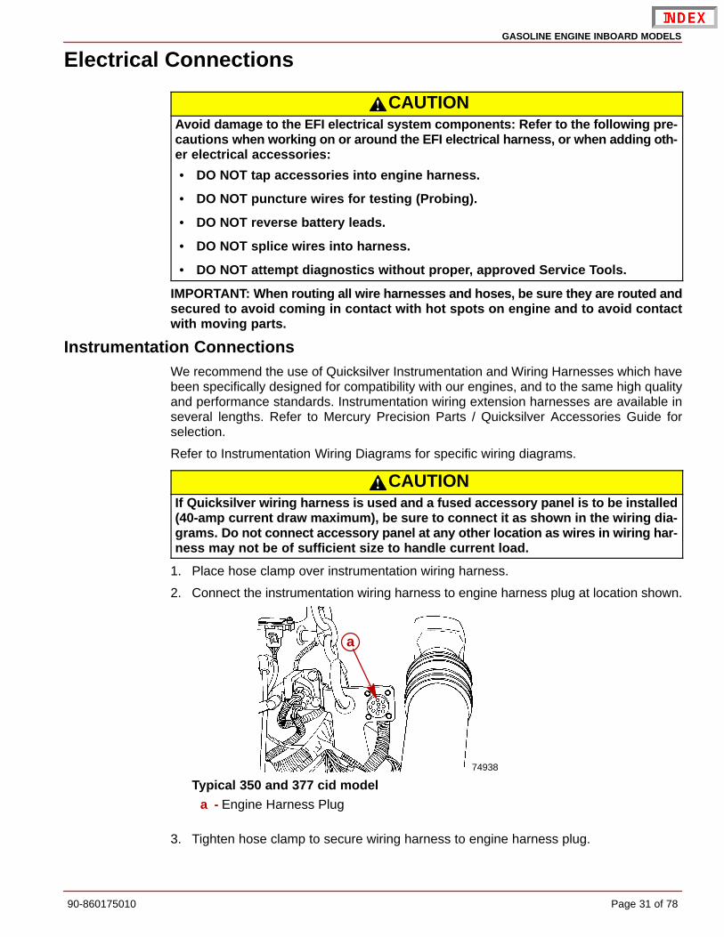
1. Place hose clamp over instrumentation wiring harness.
2. Connect the instrumentation wiring harness to engine harness plug at location shown.
74938
a
Typical 350 and 377 cid modela - Engine Harness Plug
3. Tighten hose clamp to secure wiring harness to engine harness plug.

GASOLINE ENGINE INBOARD MODELS
Page 32 of 78 90-860175010
Audio Warning System Connection
WARNINGAlarm is not external ignition-proof, therefore, DO NOT mount alarm in engine orfuel tank compartments.
1. Select a location for audio warning alarm which meets all of the following:
• alarm can be easily heard, yet is out of sight
• alarm can be easily accessed for installation and maintenance
• alarm will remain dry
• alarm is within length limits of the 18 in. PURPLE alarm wire that connects to the “I”terminal or 12 volt source on switched side of ignition switch.
NOTE: The terminal to which wire is attached must have no voltage when ignition switchis in the OFF position.
2. Place alarm in desired location. Secure alarm to wire bundle with sta-strap provided.
3. Connect PURPLE wire from alarm to any 12-volt source on switched side of ignitionswitch. Tighten connection securely and coat with Quicksilver Liquid Neoprene.
4. Connect TAN/BLUE wire from the alarm to TAN/BLUE wire from instrument harness.Ensure that bullet connector is tight.
5. Place small (transparent) decals on the bottom of the water temperature and the oilpressure gauges.
6. Place the large decal on the instrument panel or other appropriate location easily viewedby the operator.
75434
ALARM INDICATES LOWOIL OR OVERHEATING
APPLY THE PROPER DECAL TO THE DASHBOARDOR OTHER APPROPRIATE LOCATION:
AUDIO WARNING HORN WILL SOUND WHEN:1. ENGINE OIL PRESSURE IS TOO LOW,2. ENGINE WATER TEMP. IS TOO HOT, OR3. TRANSMISSION TEMPERATURE IS TOO HOT.
TO TEST THE AUDIO WARNING HORN:TURN KEY TO ON POSITION (ENGINE OFF)
b
a
a - Small Decal (Transparent)b - Large Decal

GASOLINE ENGINE INBOARD MODELS
90-860175010 Page 33 of 78
Fluid Connections
Coolant Recovery Bottle
CAUTIONAvoid engine overheating and subsequent damage to engine. The coolant recoverysystem will not operate properly without proper sealing. Plastic tubing MUST sealcompletely at connections.
1. Connect plastic tubing (from kit) to bayonet fitting on heat exchanger. Secure with tubingclamp provided.
70548
a
b
a - Plastic Tubingb - Tubing Clamp
2. Remove cap from coolant recovery reservoir and fill to FULL mark with coolant solution.Reinstall cap.
Final Engine Alignment
IMPORTANT: Engine alignment MUST BE RECHECKED with boat in the water, fueltanks filled and with a normal load on board.
Engine must be aligned so that transmission and propeller shaft coupling centerlines arealigned and coupling faces are parallel within .003 in. (0.07 mm). This applies to installationswith solid couplings as well as flexible couplings.
1. Check mating faces on transmission output flange and propeller shaft coupler to ensurethat they are clean and flat.
2. Center propeller shaft in shaft log as follows:
a. Push down and then lift shaft as far as it will move. Then place shaft in the middleof the movement.
b. Move shaft to port and then to starboard as far as shaft will move. Then place shaftin the middle of the movement.
GASOLINE ENGINE INBOARD MODELS
Page 34 of 78 90-860175010
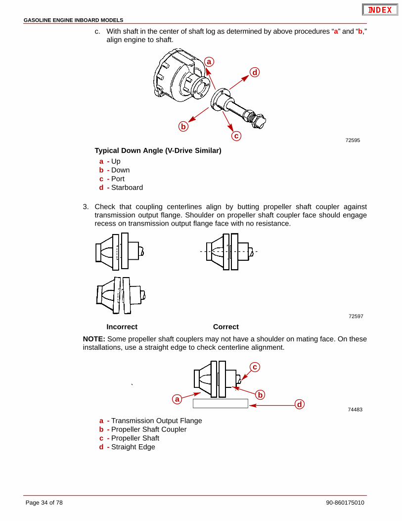
c. With shaft in the center of shaft log as determined by above procedures “a” and “b,”align engine to shaft.
72595
ad
bc
Typical Down Angle (V-Drive Similar)a - Upb - Downc - Portd - Starboard
3. Check that coupling centerlines align by butting propeller shaft coupler againsttransmission output flange. Shoulder on propeller shaft coupler face should engagerecess on transmission output flange face with no resistance.
72597
Incorrect Correct
NOTE: Some propeller shaft couplers may not have a shoulder on mating face. On theseinstallations, use a straight edge to check centerline alignment.
74483
c
dba
a - Transmission Output Flangeb - Propeller Shaft Couplerc - Propeller Shaftd - Straight Edge

GASOLINE ENGINE INBOARD MODELS
90-860175010 Page 35 of 78
4. Check for angular misalignment by hand holding coupling faces tightly together andchecking for a gap between coupling faces with a .003 in. (0.07 mm) feeler gauge.
5. Check the gap at 90 degree intervals.
75534
a
b c
Velvet Drive
50608a
a
b
bc
c
50609
Hurth
75646
a
b
c
Walter V-Drivea - Propeller Shaft Couplerb - Feeler Gaugec - Transmission Output Flange
GASOLINE ENGINE INBOARD MODELS
Page 36 of 78 90-860175010
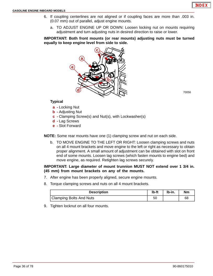
6. If coupling centerlines are not aligned or if coupling faces are more than .003 in.(0.07 mm) out of parallel, adjust engine mounts.
a. TO ADJUST ENGINE UP OR DOWN: Loosen locking nut on mounts requiringadjustment and turn adjusting nuts in desired direction to raise or lower.
IMPORTANT: Both front mounts (or rear mounts) adjusting nuts must be turnedequally to keep engine level from side to side.
70056
a
b
c
d
e
Typicala - Locking Nutb - Adjusting Nutc - Clamping Screw(s) and Nut(s), with Lockwasher(s)d - Lag Screwse - Slot Forward
NOTE: Some rear mounts have one (1) clamping screw and nut on each side.
b. TO MOVE ENGINE TO THE LEFT OR RIGHT: Loosen clamping screws and nutson all 4 mount brackets and move engine to the left or right as necessary to obtainproper alignment. A small amount of adjustment can be obtained with slot on frontend of some mounts. Loosen lag screws (which fasten mounts to engine bed) andmove engine, as required. Retighten lag screws securely.
IMPORTANT: Large diameter of mount trunnion MUST NOT extend over 1 3/4 in.(45 mm) from mount brackets on any of the mounts.
7. After engine has been properly aligned, secure engine mounts.
8. Torque clamping screws and nuts on all 4 mount brackets.
Description lb-ft lb-in. Nm
Clamping Bolts And Nuts 50 68
9. Tighten locknut on all four mounts.

GASOLINE ENGINE INBOARD MODELS
90-860175010 Page 37 of 78
10. Bend one of the tabs on the tab washer down onto the flat of the adjusting nut.
70057
ab
c
d
a - Clamping Screws and Nutsb - Locknuts On All 4 Mountsc - Tab on Tab Washerd - Measurement - 1-3/4 in. (45 mm)
NOTE: Some rear mounts have one (1) clamping screw and nut on each side.
IMPORTANT: All coupler bolts must be SAE Grade 8 (Metric Grade 10.9) or better, witha shoulder (grip length) sufficient to pass through the mating face plane of thecouplers.
11. Secure coupling together with bolts, lockwashers and nuts. Torque fasteners.
75535
a
b
a - Boltsb - Transmission Coupler
Description lb-ft lb-in. Nm
Coupling Bolts And Nuts 50 68

GASOLINE ENGINE INBOARD MODELS
Page 38 of 78 90-860175010
a. If propeller shaft coupler has set screws, remove set screws and mark dimplelocations using a transfer punch.
b. To drill dimples, remove propeller shaft coupler and drill shallow dimples at locationsmarked with punch.
c. Reinstall propeller shaft coupler and torque bolts. Install set screws and tightensecurely. Safety wire set screws to ensure they do not loosen.
50608
a
b
cd
e
a - Propeller Shaft Couplerb - Boltsc - Set Screwsd - Safety Wiree - Transmission Output Flange
Description lb-ft lb-in. Nm
Coupling Bolts And Nuts 50 68

GASOLINE ENGINE INBOARD MODELS
90-860175010 Page 39 of 78
Engine Connections
Seawater Pickup Pump Connection1. On All Models Not Equipped With Walter V-Drive Transmission: Remove shipping
cap and connect seawater inlet hose to the lower fitting.
75533a
a - Seawater Inlet Hose Attached To Lower Fitting
2. On All Models With Walter V-Drive Transmissions: Connect water inlet hose to thefitting on the transmission.
75191
aa - Water Inlet Hose Attached To Fitting
GASOLINE ENGINE INBOARD MODELS
Page 40 of 78 90-860175010
Throttle Cable Installation and AdjustmentCarbureted Models
IMPORTANT: When installing throttle cable, be sure that cables are routed in such away as to avoid sharp bends and/or contact with moving parts. DO NOT fasten anyitems to throttle cable.
1. Lubricate cable ends and barrels.
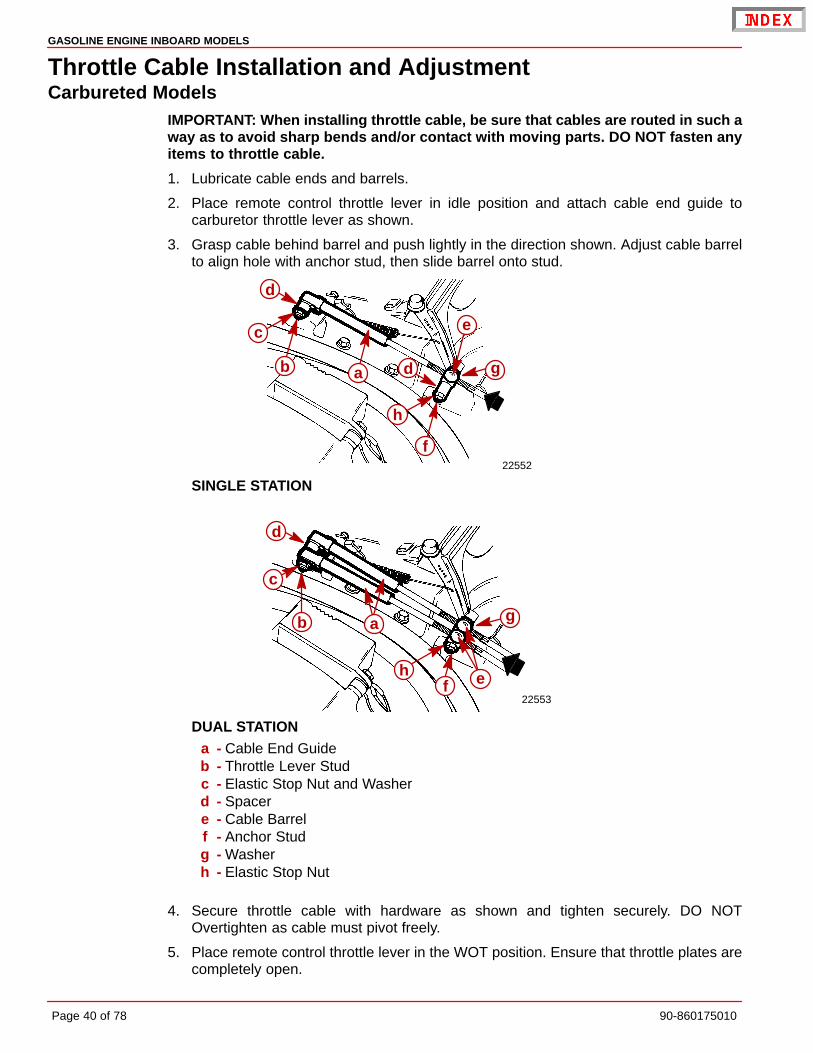
2. Place remote control throttle lever in idle position and attach cable end guide tocarburetor throttle lever as shown.
3. Grasp cable behind barrel and push lightly in the direction shown. Adjust cable barrelto align hole with anchor stud, then slide barrel onto stud.
22552
ab
c
d
d
e
f
g
h
SINGLE STATION
22553
ab
c
ef
d
h
g
DUAL STATIONa - Cable End Guideb - Throttle Lever Studc - Elastic Stop Nut and Washerd - Spacere - Cable Barrelf - Anchor Studg - Washerh - Elastic Stop Nut
4. Secure throttle cable with hardware as shown and tighten securely. DO NOTOvertighten as cable must pivot freely.
5. Place remote control throttle lever in the WOT position. Ensure that throttle plates arecompletely open.

GASOLINE ENGINE INBOARD MODELS
90-860175010 Page 41 of 78
6. Return remote control throttle lever to idle position and ensure that throttle lever contactsidle speed adjustment screw at WOT.
7039271159
b
ab c
d
d
a
a - Throttle Shaft Leverb - Carburetor Body Castingc - Throttle Leverd - Idle Speed Adjustment Screw
Black Scorpion ModelsIMPORTANT: When installing throttle cable, be sure that cables are routed in such away as to avoid sharp bends and/or contact with moving parts. DO NOT fasten anyitems to throttle cable.
1. Place remote throttle lever in idle position and attach cable to throttle body, followingcable manufacturer’s instructions.
2. Adjust cable so that it can be placed on both studs simultaneously.
3. Place cable over studs. DO NOT adjust cable after installation.
4. Secure throttle cable with hardware as shown and tighten securely. Loosen locknut 1/2turn.
74941
a
bc
a - Cable Endb - Cable Barrelc - Locknut and Flat Washer

GASOLINE ENGINE INBOARD MODELS
Page 42 of 78 90-860175010
Shift Cable Installation And Adjustment
IMPORTANT: When installing shift cables, be sure that cables are routed in such away as to avoid contact with moving parts and/or sharp bends All bends must makegreater than an 8 in. (203 mm) radius. DO NOT fasten any items to shift cables.
Shift cable must be hooked up to remote control before starting installation and adjustmentprocedures. Refer to Transmission - Propeller Rotation, as previously outlined in the frontof this manual, for transmission shift lever direction of movement versus propeller shaftoutput direction of rotation.
Damage caused to transmission as a result of improper shift lever positioning will not becovered by warranty.
To ensure proper shift and throttle operation, we recommend the use of a Quicksilver remotecontrol and cables. Refer to Mercury Precision Parts / Quicksilver Accessories Guide.
Shift Cable Travel 2-3/4 in. (70 mm)
Velvet Drive Transmissions
IN-LINE AND REMOTE V-DRIVE
IMPORTANT: Velvet Drive Transmission Warranty is jeopardized if the shift leverpoppet ball or spring is permanently removed, if the shift lever is repositioned orchanged in any manner or if remote control and cable do not position shift levercorrectly.
22457
F N R– –
FR
a
b
c
d
e
a - Transmission Shift Leverb - Shift Lever MUST BE Over This Letter In FORWARDc - Shift Lever MUST BE Over This Letter In REVERSEd - Poppet Ball MUST BE Centered in Detent Hole for Each F-N-R Position
(Forward Gear Shown)e - Install Shift Lever Stud in This Hole, If Necessary, To Center Poppet Ball in
Forward and Reverse Detent Holes

GASOLINE ENGINE INBOARD MODELS
90-860175010 Page 43 of 78
1. Verify shift cable stud is in appropriate stud hole as indicated. Tighten elastic stop nutsecurely.
50947
a
a - 5.7L Shift Cable Anchor Stud Hole
2. Place remote control shift lever and transmission shift lever in neutral position.
3. Remove nuts and washers from shift cable attaching studs.
4. Locate center of remote control and control shift cable play (backlash), as follows:
a. Ensure that remote control is in neutral position.
b. Push in on control cable end with enough pressure to remove play and mark position“a” on tube.
c. Pull out on control cable end with enough pressure to remove play and mark position“b” on tube.
d. Measure distance between marks “a” and “b,” and mark position “c,” half-waybetween marks “a” and “b.”
22024
a
b c
c
5. Center cable-end play, then adjust cable barrel to align holes in barrel and in cable endguide, with attaching points on transmission.
6. Temporarily install shift cable. Do not secure at this time.
7. Place remote control shift lever in FORWARD gear position and check position oftransmission shift lever. Shift lever must be positioned as previously indicated.
8. Place remote control lever in REVERSE gear position and again check shift leverposition. Lever must be positioned as previously indicated.
GASOLINE ENGINE INBOARD MODELS
Page 44 of 78 90-860175010
9. If transmission shift lever will position properly in one gear, but not in the other, recheckshift cable adjustment. If transmission shift lever will not position properly in either gear,move transmission shift lever stud, from top hole in shift lever to bottom hole, andrecheck for proper positioning. If proper positioning is still not obtained, remote controldoes not provide sufficient shift cable travel and must be replaced.
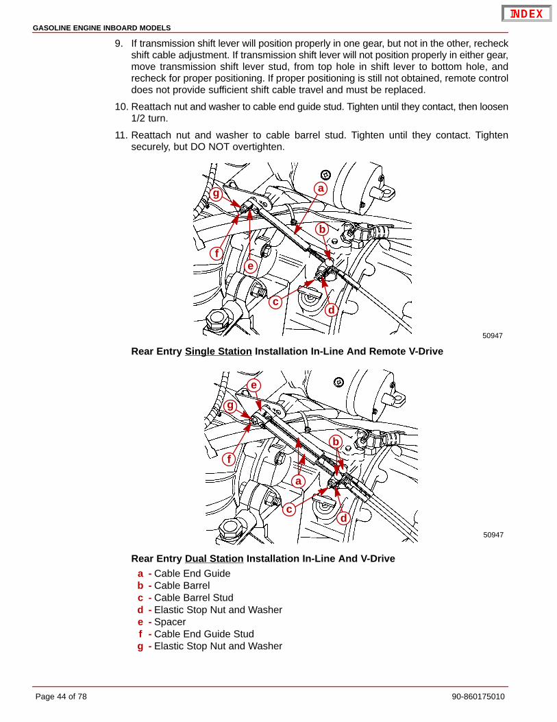
10. Reattach nut and washer to cable end guide stud. Tighten until they contact, then loosen1/2 turn.
11. Reattach nut and washer to cable barrel stud. Tighten until they contact. Tightensecurely, but DO NOT overtighten.
50947
a
b
cd
ef
g
Rear Entry Single Station Installation In-Line And Remote V-Drive
50947
a
b
cd
e
f
g
Rear Entry Dual Station Installation In-Line And V-Drivea - Cable End Guideb - Cable Barrelc - Cable Barrel Studd - Elastic Stop Nut and Washere - Spacerf - Cable End Guide Studg - Elastic Stop Nut and Washer

GASOLINE ENGINE INBOARD MODELS
90-860175010 Page 45 of 78
50946
a
b
c
d
ef
g
Front Entry Single Station Installation In-Line And V-Drive
50946
a
b
c
d
e
f
g
Front Entry Dual Station Installation In-Line And V-Drivea - Cable End Guideb - Cable Barrelc - Cable Barrel Studd - Elastic Stop Nut and Washere - Spacerf - Cable End Guide Studg - Elastic Stop Nut and Washer
NOTE: For models equipped with a dual station shift bracket such as the one shown, referto shift cable manufacturer’s instructions for adjusting the cable. Shift lever must bepositioned as stated in the preceding steps.
22457
Dual Station Shift Bracket (Not Quicksilver)

GASOLINE ENGINE INBOARD MODELS
Page 46 of 78 90-860175010
5000 SERIES (8 DEGREE DOWN ANGLE AND V-DRIVE)
For Left-Hand Propeller Shaft Rotation: Shift cable hookup at remote control must resultin shift cable end guide moving in direction “A” when remote control handle is placed inforward position.
For Right-Hand Propeller Shaft Rotation: Shift cable hookup at remote control mustresult in shift cable end guide moving in direction “B” when remote control handle is placedin forward position.
23242
A
B
Remote control must provide a total shift cable travel (at transmission end) of at least2-3/4 in. (70 mm). This is necessary to position transmission shift lever fully in the forwardand reverse gear positions. Insufficient shift cable travel will cause transmission to slip andeventually fail.
72602
a
a - 2-3/4 in. (70 mm) Minimum
IMPORTANT: The distance between studs (Dimension “c”) shown in the followingillustration is set at 7-1/8 in. (181 mm).
73284
b c
db
a
8° Down Angle Shown (V-Drive Similar)a - Shift Leverb - Anchor Studc - Dimension Between Studs - 7-1/8 In. (181 mm)d - Shift Cable Bracket

GASOLINE ENGINE INBOARD MODELS
90-860175010 Page 47 of 78
WARNINGAvoid serious injury or property damage caused by improper shifting. Anchor studfor shift cable must be installed in the correct hole.
1. Be certain anchor stud is installed in the front hole as shown in the illustration following.
73284
ab
a - Shift Cable Bracketb - Anchor Stud In Front Hole
2. Place remote control shift lever and transmission shift lever in neutral position.
3. Remove nuts and washers from shift cable attaching studs.
4. Locate center of remote control and control shift cable play (backlash) as follows:
a. Check that remote control is in neutral position.
b. Push in on control cable end with enough pressure to remove play; mark position“a” on tube.
c. Pull out on control cable end with enough effort to remove play; mark position “b”on tube.
d. Measure distance between marks “a” and “b;” mark position “c,” half-way betweenmarks “a” and “b.”
72603
cb
c a
5. Center cable-end play, then adjust cable barrel to align holes in barrel and in cable endguide with attaching points on transmission.
6. Temporarily install shift cable. Do not secure at this time.
7. Place remote control shift lever in gear and check position of transmission shift lever.Shift lever must be positioned in the desired detent hole.
IMPORTANT: Transmission is fully in gear when shift lever comes to a stop in eitherdirection.
GASOLINE ENGINE INBOARD MODELS
Page 48 of 78 90-860175010
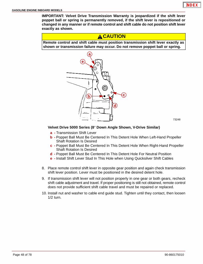
IMPORTANT: Velvet Drive Transmission Warranty is jeopardized if the shift leverpoppet ball or spring is permanently removed, if the shift lever is repositioned orchanged in any manner or if remote control and shift cable do not position shift leverexactly as shown.
CAUTIONRemote control and shift cable must position transmission shift lever exactly asshown or transmission failure may occur. Do not remove poppet ball or spring.
73248
e
b c
a
d
Velvet Drive 5000 Series (8° Down Angle Shown, V-Drive Similar)a - Transmission Shift Leverb - Poppet Ball Must Be Centered In This Detent Hole When Left-Hand Propeller
Shaft Rotation Is Desiredc - Poppet Ball Must Be Centered In This Detent Hole When Right-Hand Propeller
Shaft Rotation Is Desiredd - Poppet Ball Must Be Centered In This Detent Hole For Neutral Positione - Install Shift Lever Stud In This Hole when Using Quicksilver Shift Cables
8. Place remote control shift lever in opposite gear position and again check transmissionshift lever position. Lever must be positioned in the desired detent hole.
9. If transmission shift lever will not position properly in one gear or both gears, recheckshift cable adjustment and travel. If proper positioning is still not obtained, remote controldoes not provide sufficient shift cable travel and must be repaired or replaced.
10. Install nut and washer to cable end guide stud. Tighten until they contact, then loosen1/2 turn.

GASOLINE ENGINE INBOARD MODELS
90-860175010 Page 49 of 78
11. Install nut and washer to cable barrel stud. Tighten until they contact. Tighten securely,but DO NOT overtighten.
71780 71972
ab
c
e
e
f
c
db
g
Typical Single Cable Installation - Rear Approacha - Cable End Guideb - Spacer (As Required)c - Elastic Stop Nut and Washerd - Bushingse - Cable Barrel Locationf - Cable Barrel Studg - Cable End Guide Stud
71897 50073
g
b
ea
dc
f
e
Typical Dual Cable Installation - Rear Approacha - Cable End Guideb - Spacer (As Required)c - Elastic Stop Nut and Washerd - Bushingse - Cable Barrel Locationf - Cable Barrel Studg - Cable End Guide Stud

GASOLINE ENGINE INBOARD MODELS
Page 50 of 78 90-860175010
Hurth Transmissions
IMPORTANT: These Hurth transmissions are full reversing transmissions. Directionof output/propeller rotation is determined by hookup of shift cable at remote control.
Shift cable must be hooked up to remote control before starting installation and adjustmentprocedures. Refer to Transmission - Propeller Rotation, as previously outlined in the frontof this manual, for transmission shift lever direction of movement versus propeller shaftoutput direction of rotation.
For Right Hand Propeller Rotation – Shift cable hookup at remote control must result inshift cable end guide moving in direction “A” when remote control handle is placed inforward position.
For Left Hand Propeller Rotation – Shift cable hookup at remote control must result in shiftcable end guide moving in direction “B” when remote control handle is placed in forwardposition.
23242
A
B
WARNINGAvoid serious injury or property damage caused by improper shifting. Anchor studfor shift cable must be installed in the correct hole.
1. Be certain anchor stud is installed in the correct mount hole as shown by the followingillustration.
73588
71020
a
c
ba
Shift Cable Bracket - Anchor Stud Positionsa - Cable Bracketb - Quicksilver Shift Cable Anchor Stud Location - 630A and 630Vc - Quicksilver Shift Cable Anchor Stud Location - 800A
IMPORTANT: When installing shift cables, be sure that cables are routed in such away as to avoid contact with moving parts and/or sharp bends All bends must makegreater than an 8 inch ( 203 mm) radius. DO NOT fasten any items to shift cables.

GASOLINE ENGINE INBOARD MODELS
90-860175010 Page 51 of 78
2. Check shift lever positioning as indicated:
IMPORTANT: Check that shift lever is positioned approximately 10° aft of verticalwhen in the neutral detent position and that the distance “c” between studs in thefollowing is set at 7-1/8 in. (181 mm). If necessary, loosen clamping bolt and positionlever so that dimension “c” is as shown when in the neutral detent position andretighten bolt.
73587
a
b
d
c
Typical Hurth Transmission Showna - Shift Leverb - Lever in Neutral Detent 10° Aft of Verticalc - Dimension Between Studs - 7-1/8 in. (181 mm)d - Clamping Bolt
3. Place remote control shift lever, and transmission shift lever, in neutral position.
4. Remove nuts and washers from shift cable attaching studs.
5. Locate center of remote control and control shift cable play (backlash), as follows:
a. Check that remote control is in neutral position.
b. Push in on control cable end with enough pressure to remove play, and markposition “a” on tube.
c. Pull out on control cable end with enough pressure to remove play, and markposition “b” on tube.
d. Measure distance between marks “a” and “b,” and mark position “c,” half-waybetween marks “a” and “b.”
22024
a
b c
c
6. Center cable-end play, then adjust cable barrel to align holes in barrel, and in cable endguide, with attaching points on transmission.
GASOLINE ENGINE INBOARD MODELS
Page 52 of 78 90-860175010
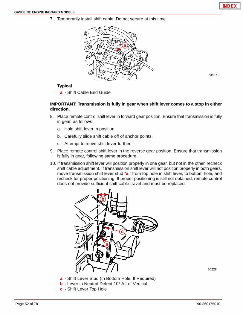
7. Temporarily install shift cable. Do not secure at this time.
73587
a
Typicala - Shift Cable End Guide
IMPORTANT: Transmission is fully in gear when shift lever comes to a stop in eitherdirection.
8. Place remote control shift lever in forward gear position. Ensure that transmission is fullyin gear, as follows:
a. Hold shift lever in position.
b. Carefully slide shift cable off of anchor points.
c. Attempt to move shift lever further.
9. Place remote control shift lever in the reverse gear position. Ensure that transmissionis fully in gear, following same procedure.
10. If transmission shift lever will position properly in one gear, but not in the other, recheckshift cable adjustment. If transmission shift lever will not position properly in both gears,move transmission shift lever stud “a,” from top hole in shift lever, to bottom hole, andrecheck for proper positioning. If proper positioning is still not obtained, remote controldoes not provide sufficient shift cable travel and must be replaced.
50228
a
b
c
a - Shift Lever Stud (In Bottom Hole, If Required)b - Lever in Neutral Detent 10° Aft of Verticalc - Shift Lever Top Hole

GASOLINE ENGINE INBOARD MODELS
90-860175010 Page 53 of 78
11. Reattach locknut and washer to cable end guide stud. Tighten until they contact, thenloosen 1/2 turn.
12. Reattach locknut and washer to cable barrel stud. Tighten until they contact. Tightensecurely, but DO NOT overtighten.
NOTE: To change cable approach direction on single or dual station installations, only thespacers/bushings have to be switched to the opposite stud (the studs are identical).
7358971210
a
b
cd
f
e
bg
h
e
Typical Single Cable - Forward Entrya - Cable End Guideb - Locknut and Washerc - Spacer (Fits over Bushings)d - Bushingse - Cable Barrel Locationf - Spacer (Fit over Stud)g - Cable Barrel Studh - Cable End Guide Stud
7358750229
e
e
fa
b
bc
dg
h
Typical Single Cable - Rear Entrya - Cable End Guideb - Locknut and Washerc - Spacer (Fits over Bushings)d - Bushingse - Cable Barrel Locationf - Spacer (Fit over Stud)g - Cable Barrel Studh - Cable End Guide Stud

GASOLINE ENGINE INBOARD MODELS
Page 54 of 78 90-860175010
73590
71211
e
e
b
b
a
c
d
g
f
Typical Dual Cable - Forward Entrya - Cable End Guidesb - Locknut and Washerc - Spacer (Fits over Stud)d - Bushingse - Cable Barrel Locationsf - Cable Barrel Studg - Cable End Guide Stud
73591
50073
a
b
c
d
e
e
b
f
g
Typical Dual Cable - Rear Entrya - Cable End Guidesb - Locknut and Washerc - Spacer (Fits over Stud)d - Bushingse - Cable Barrel Locationsf - Cable Barrel Studg - Cable End Guide Stud

GASOLINE ENGINE INBOARD MODELS
90-860175010 Page 55 of 78
Predelivery Preparation
Once the power package installation is complete, the following final steps should be takento prepare power package for delivery to the customer. It is the boat manufacturer’sresponsibility to perform these procedures, or to make arrangement with the dealer to havethese procedures completed.
Propeller Selection
GENERAL INFORMATION
IMPORTANT: Installed propeller must allow engine to run at its specified maximumWOT rpm. Use an accurate service tachometer to verify engine operating rpm.
It is the responsibility of the boat manufacturer and/or the selling dealer to equip the powerpackage with the correct propeller. Refer to Quicksilver publication - Everything You NeedTo Know About Propellers P/N 90-8614492. Specified engine WOT and operating rpmrange are listed in the Mercury MerCruiser Operation, Maintenance and Warranty Manualattached to the engine.
Select a propeller that will allow the engine power package to operate at or near the top endof the recommended wide-open-throttle operating rpm range with a normal load.
If full throttle operation is below the recommended range, the propeller must be changedto prevent loss of performance and possible engine damage. On the other hand, operatingan engine above the recommended operating rpm range will cause higher than normal wearand/or damage.
After initial propeller selection, the following common problems may require that thepropeller be changed to a lower pitch.
• Warmer weather and greater humidity cause a loss of rpm.
• Operating in a higher elevation causes a loss of rpm.
• Operating with increased load (additional passengers, pulling skiers) causes a loss ofrpm.
For better acceleration, such as is needed for water skiing, use the next lower pitchpropeller. Do not operate at full throttle when using the lower pitch propeller but not pullingskiers.
Because of the many variables of boat design, only testing will determine the best propellerfor a particular application. Available propellers are listed in the Mercury Precision Parts /Quicksilver Accessories Guide.
See BOAT IN THE WATER TESTS, Maximum RPM Test at the back of this manual.
GASOLINE ENGINE INBOARD MODELS
Page 56 of 78 90-860175010
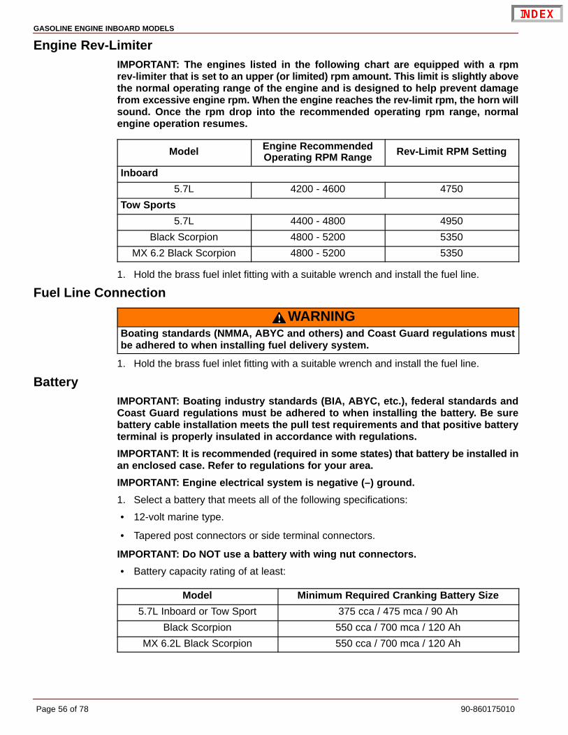
Engine Rev-LimiterIMPORTANT: The engines listed in the following chart are equipped with a rpmrev-limiter that is set to an upper (or limited) rpm amount. This limit is slightly abovethe normal operating range of the engine and is designed to help prevent damagefrom excessive engine rpm. When the engine reaches the rev-limit rpm, the horn willsound. Once the rpm drop into the recommended operating rpm range, normalengine operation resumes.
Model Engine RecommendedOperating RPM Range Rev-Limit RPM Setting
Inboard
5.7L 4200 - 4600 4750
Tow Sports
5.7L 4400 - 4800 4950
Black Scorpion 4800 - 5200 5350
MX 6.2 Black Scorpion 4800 - 5200 5350
1. Hold the brass fuel inlet fitting with a suitable wrench and install the fuel line.
Fuel Line Connection
WARNINGBoating standards (NMMA, ABYC and others) and Coast Guard regulations mustbe adhered to when installing fuel delivery system.
1. Hold the brass fuel inlet fitting with a suitable wrench and install the fuel line.
BatteryIMPORTANT: Boating industry standards (BIA, ABYC, etc.), federal standards andCoast Guard regulations must be adhered to when installing the battery. Be surebattery cable installation meets the pull test requirements and that positive batteryterminal is properly insulated in accordance with regulations.
IMPORTANT: It is recommended (required in some states) that battery be installed inan enclosed case. Refer to regulations for your area.
IMPORTANT: Engine electrical system is negative (–) ground.
1. Select a battery that meets all of the following specifications:
• 12-volt marine type.
• Tapered post connectors or side terminal connectors.
IMPORTANT: Do NOT use a battery with wing nut connectors.
• Battery capacity rating of at least:
Model Minimum Required Cranking Battery Size
5.7L Inboard or Tow Sport 375 cca / 475 mca / 90 Ah
Black Scorpion 550 cca / 700 mca / 120 Ah
MX 6.2L Black Scorpion 550 cca / 700 mca / 120 Ah

GASOLINE ENGINE INBOARD MODELS
90-860175010 Page 57 of 78
BATTERY CABLES
1. Select proper size positive (+) and negative (–) battery cables, using chart. Batteryshould be located as close to engine as possible.
IMPORTANT: Terminals must be soldered to cable ends to ensure good electricalcontact. Use electrical grade (resin flux) solder only. DO NOT use acid flux solder, asit may cause corrosion and a subsequent failure.
Cable Length Cable Gauge
Up to 3-1/2 ft. (1.1m) 4 (25 mm2)
3-1/2 - 6 ft. (1.1-1.8m) 2 (35 mm2)
6 - 7-1/2 ft. (1.8-2.3m) 1 (50 mm2)
7-1/2 - 9-1/2 ft. (2.3-2.9m) 0 (50 mm2)
9-1/2 - 12 ft. (2.9-3.7m) 00 (70 mm2)
12 - 15 ft. (3.7-4.6m) 000 (95 mm2)
15 - 19 ft. (4.6-5.8m) 0000 (120 mm2)
MULTIPLE EFI ENGINE BATTERY PRECAUTIONS
Batteries: Boats with multi-engine EFI power packages require each engine be connectedto its own battery. This ensures that the engine’s Electronic Control Module (ECM) has astable voltage source.
Battery Switches: Battery switches should always be positioned so each engine is runningoff its own battery. DO NOT operate engines with switches in BOTH or ALL position. In anemergency, another engine’s battery can be used to start an engine with a dead battery.
Battery Isolators: Isolators can be used to charge an auxiliary battery used for poweringaccessories in the boat. They should not be used to charge the battery of another enginein the boat unless the type of isolator is specifically designed for this purpose.
NOTE: Sure Power Industries Inc., Model 32023A meets this design specification.
1. The boat may have 2 engines connected to a single Model 32023A battery isolator.
2. The Model 32023A battery isolator is connected to 2 banks of batteries.
3. Each bank contains 2 batteries with the cranking battery for 1 engine in each bank.
4. The second battery in each bank is connected in parallel to the cranking battery.
5. The Model 32023A battery isolator is designed for this type of use; 2 battery banks, 2charging sources, 120 amps (maximum alternator output).
6. When the engines are running, either engine’s alternator could be charging either bankof batteries through the Model 32023A battery isolator.
Any other manufacturer’s battery isolator that is the same type as the Sure Power Inc.,Model 32023A could also be used.
Generators: The generator’s battery should be considered another engine’s battery.

GASOLINE ENGINE INBOARD MODELS
Page 58 of 78 90-860175010
BATTERY CONNECTION
IMPORTANT: Engine electrical system is negative (–) ground.
1. Connect engine positive (+) battery cable (usually RED) to positive (+) battery terminal.
2. Connect engine negative (–) battery cable (usually BLACK) to negative (–) batteryterminal.
3. Connect Power Trim pump BLACK (–) battery cable to negative (–) battery terminal andtrim pump RED (+) battery cable to positive (+) battery terminal.
4. Make sure that all battery terminal connections are tight. Then spray terminals with abattery connection sealant to help retard corrosion.
Test Running Engine
WARNINGIf engine is to be tested with boat out of water, the propeller must be removed toavoid injury.
IMPORTANT: If engine is to be tested on land, water must be supplied to seawaterpickup pump. DO NOT run engine above 1500 rpm.
WARNINGDo not leave helm unattended when making test with boat in the water.
1. Ensure that cooling system drain plugs, petcocks and hoses are installed and tight.
NOTE: Refer to appropriate Mercury MerCruiser Operation, Maintenance and WarrantyManual for operating specifications. Refer to appropriate Mercury MerCruiser ServiceManual for fluid capacity information.
2. Check crankcase oil level.
IMPORTANT: Oil level in monitor will rise and lower during drive operation. Alwayscheck oil level when drive is cool and engine is shut down.
3. Check drive belt tension.
4. Test Audio Warning System in accordance with instructions on instrumentation paneldecal.
5. Start engine and run at idle rpm until water temperature is normal.
6. Watch all gauges for normal readings.
7. Inspect engine compartment for water, oil, fuel and exhaust leaks.
8. Stop the engine and turn the key switch OFF.

GASOLINE ENGINE INBOARD MODELS
90-860175010 Page 59 of 78
Boat-In-The-Water TestsIMPORTANT: Engine alignment MUST BE CHECKED with boat in the water, fuel tanksfilled, and with a normal load on board.
NOTE: On Tow Sport Applications: If during testing for a particular application, youexperience fuel starvation in sharp high speed turns, baffles or a fuel sump may be neededin the tank to help correct this condition.
CAUTIONAvoid engine damage. Ensure that cooling water is supplied to the engine if it willbe run with boat out of the water. See instructions in the Operation, Maintenanceand Warranty Manual entitled “Flushing Cooling System” for instructions on con-necting flush device.
ENGINE IDLE SPEED ADJUSTMENT (CARBURETED MODELS)
CAUTIONAvoid engine damage. Ensure that cooling water is supplied to the engine if it willbe run with boat out of the water. See instructions in the Operation, Maintenanceand Warranty Manual entitled “Flushing Cooling System” for instructions on con-necting flush device.
The engine should idle at rpm (as specified in the Operation, Maintenance and WarrantyManual) with engine at normal operating temperature. If idle speed is incorrect, proceed asfollows:
IMPORTANT: In order to properly set idle speed, the ignition module MUST BE lockedin the Base Timing Mode. This is necessary because of the Idle Speed Control featurethat exists in the ignition module. This must be done before the key switch is turnedto the ON or START position.
1. Connect a shop tachometer to engine.
2. Using a jumper wire, connect the ignition system Timing Lead (PUR/WHT wire) to agood engine ground (–). This locks the ignition module into the Base Timing Mode. Referto Engine Wiring Harness diagram in this manual.
3. Start engine and place the remote control lever in NEUTRAL, idle position.
4. Adjust idle speed to 650 rpm.
5. Stop engine. Readjust cable barrel and reinstall the throttle cable.
IMPORTANT: Be sure to disconnect the jumper wire from the ignition system test leadbefore attempting to resume normal operations. If the jumper wire is left in place, theignition module will operate in the Base Timing Mode. This means that the additionaltiming advance features would not be functioning.
6. Remove the jumper wire from the timing lead.

GASOLINE ENGINE INBOARD MODELS
Page 60 of 78 90-860175010
ENGINE IDLE SPEED ADJUSTMENT (BLACK SCORPION MODELS)
CAUTIONAvoid engine damage. Ensure that cooling water is supplied to the engine if it willbe run with boat out of the water. See instructions in the Operation, Maintenanceand Warranty Manual entitled “Flushing Cooling System,” for instructions on con-necting flush device.
Engine should idle at rpm (as specified in Operation, Maintenance and Warranty Manual)with engine at normal operating temperature. If idle speed is incorrect, proceed as follows:
1. Ensure that throttle cable has been adjusted properly.
2. If idle speed is still not correct, it may be necessary to perform EFI System DiagnosticTests on the idle circuit. Refer to the appropriate Mercury MerCruiser Service Manualfor procedures.
WIDE-OPEN-THROTTLE TEST
IMPORTANT: To run engine at full throttle before the break-in period is complete,follow this procedure.
1. Start engine and run at idle rpm until normal operating temperature is reached.
2. Run boat up on plane.
3. Advance engine rpm (in 200 rpm increments) until engine reaches its maximum ratedrpm.
To test if the correct propeller has been installed, operate boat (with normal load on board)at WOT and check rpm with an accurate tachometer. Engine rpm should be near top of thespecified range so that, under a heavy load, engine speed will not fall below specifications.If engine speed is too high, replace propeller with a higher pitch propeller. Normally a 1 inchpropeller pitch change causes an rpm change of 150 rpm.
4. Shut off engine.
5. Check coolant level and add coolant if necessary.

GASOLINE ENGINE INBOARD MODELS
90-860175010 Page 61 of 78
Cold Weather and Extended Storage Draining Instructions
CAUTIONIf boat is to remain in water after draining, seawater inlet hose must be removed andplugged to prevent a siphoning action that may occur, allowing seawater to flowfrom the drain holes or removed hoses.
CAUTIONSeawater section of cooling system MUST BE COMPLETELY drained for winterstorage, or immediately after cold weather use, if the possibility of freezing temper-atures exist. Failure to comply may result in trapped water causing freeze and/orcorrosion damage to engine.
IMPORTANT: Boat must be as level as possible to ensure complete draining ofcooling system.
IMPORTANT: Mercury MerCruiser recommends that propylene glycol (a nontoxicand environmentally safe) antifreeze be used in the seawater section of the coolingsystem for cold weather or extended storage. Make sure that the propylene glycolantifreeze contains a rust inhibitor and is recommended for use in marine engines.Be certain to follow the propylene glycol manufacturer’s recommendations.
1. Ensure engine is as level as possible to ensure complete draining of cooling system.
2. Remove drain plugs from the following locations:
a. Port Side - from cylinder block.
CAUTIONAvoid product damage. Do not disturb the Y-fitting when removing the drain plug.There is an ignition control “Knock Sensor” in the upper hole of the fitting. This sen-sor must not be loosened or removed. It is tightened to a critical specification at thefactory.
b. Starboard Side - from Y-fitting.
a
a - Y-fitting

GASOLINE ENGINE INBOARD MODELS
Page 62 of 78 90-860175010
c. Fuel cooler, if equipped.
d. Bottom of exhaust manifolds (port and stbd).
75081ab
c
a - Cylinder Block Drain Locationb - Port Side Water Tube Drain Locationc - Exhaust Manifold Drain Location
3. Repeatedly clean out drain holes using a stiff piece of wire. Do this until entire systemis drained.
NOTE: It may be necessary to lift or bend hoses to allow water to drain completely. Crankengine over slightly to purge any water trapped in seawater pickup pump. Do not allowengine to start.
4. Remove hoses from the following locations:
a. On All Models Not Equipped With Walter V-Drive: Water inlet hose (bottom) andtransmission cooler hose (top) from seawater pump.
75533a
b
a - Seawater Inlet Hoseb - Transmission Cooler Hose

GASOLINE ENGINE INBOARD MODELS
90-860175010 Page 63 of 78
b. Hose from engine circulating pump or remove drain plug, if equipped..
76038
ab
a - Engine Circulating Pump Hoseb - Drain Plug (if equipped)
c. Water inlet hose from Walter V-Drive if equipped.
75191
a
a - Water Inlet Hose Attached To Fitting

GASOLINE ENGINE INBOARD MODELS
Page 64 of 78 90-860175010
5. Turn engine over for 1 to 2 seconds to thoroughly drain system.
6. After cooling system has been drained completely, install drain plugs, reconnect hosesand tighten all hose clamps securely.
7. For additional assurance against freezing and corrosion in the internal water passages:
a. Remove the thermostat housing and thermostat.
b. Fill the engine seawater cooling system with a mixture of antifreeze and tap water.Follow the manufacturer’s recommendation to protect engine to the lowesttemperature that it will be exposed to during cold weather or extended storage.
c. Reinstall thermostat and cover.
d. Torque screws with lockwashers to 30 lb-ft (41 Nm).
NOTE: Hoses shown removed for visual clarity. Do not remove hoses.
74493
a
b
c
d
e
a - Thermostat Housingb - Gasketc - Thermostatd - Spacere - Thermostat Housing-to-Intake Manifold Gasket

GASOLINE ENGINE INBOARD MODELS
90-860175010 Page 65 of 78
Closed Cooled (Coolant) ModelsIMPORTANT: Closed cooling section must be kept filled year-round withrecommended coolant. If engine will be exposed to freezing temperatures, make sureclosed cooling section is filled with an ethylene glycol antifreeze and water solutionproperly mixed to protect engine to lowest temperature to which it will be exposed.
IMPORTANT: Do not use Propylene Glycol Antifreeze in the closed cooling sectionof the engine.
1. Ensure engine is as level as possible to ensure complete draining of cooling system.
2. Remove drain plug from port and starboard exhaust manifolds.
74165a
a - Exhaust Manifold Drain Plug
3. Repeatedly clean out all drain holes using a stiff piece of wire. Do this until entire systemis drained.
4. Remove end caps from the heat exchanger.
74638
a
a - End Cap
IMPORTANT: Use compressed air to blow any remaining water from the tubes in theheat exchanger.
NOTE: It may be necessary to lift or bend hoses to allow water to drain completely. Crankengine over slightly to purge any water trapped in seawater pickup pump. Do not allowengine to start.
5. Disconnect water inlet (bottom) hose from the inlet side of the seawater pump.

GASOLINE ENGINE INBOARD MODELS
Page 66 of 78 90-860175010
6. On All Models Not Equipped With Walter V-Drive: Remove upper hose fromseawater pump.
75533a
b
a - Seawater Inlet Hoseb - Upper Seawater Hose
7. Remove drain plug from fuel cooler.
74988a
a - Fuel Cooler Drain Plug
8. Water inlet hose from Walter V-Drive if equipped.
75191
a
a - Water Inlet Hose Attached To Fitting
9. Reconnect all hoses, reinstall heat exchanger end caps with new gaskets using PerfectSeal, and reinstall drain plugs.

GASOLINE ENGINE INBOARD MODELS
90-860175010 Page 67 of 78
THIS PAGE IS INTENTIONALLY BLANK

GASOLINE ENGINE INBOARD MODELS
Page 68 of 78 90-860175010
Wiring Diagrams
Instrumentation
SINGLE STATION INSTALLATIONS - TYPICAL
73371
BLK = BLACKBLU = BLUEBRN = BROWNGRY = GRAYGRN = GREENORN = ORANGEPNK = PINKPUR = PURPLERED = REDTAN = TAN
WHT = WHITEYEL = YELLOWLIT = LIGHT
DRK = DARK
a
bc d
e
fh
ig
j

GASOLINE ENGINE INBOARD MODELS
90-860175010 Page 69 of 78
Refer to gauge manufacturer’s instructions for specific connections.
NOTE: 1 Connect Wires Together with Screw and Hex Nut; Apply Liquid Neoprene toConnection and Slide Rubber Sleeve over Connection.
NOTE: 2 Power for a Fused Accessory Panel May Be Taken from This Connection. LoadMust Not Exceed 40 Amps. Panel Ground Wire Must Be Connected to Instrument TerminalThat Has an 8-Gauge BLACK (Ground) Harness Wire Connected to it.
NOTE: 3 Taped back BROWN-WHITE wire may be used for an accessory. LOAD MUSTNOT EXCEED 5 AMPS.
a - Audio Warning Buzzerb - Tachometerc - Oil Pressured - Water Temperaturee - Battery Meter
f - Ignition Switchg - Read/Observe NOTE 1
h - Read/Observe NOTE 1 and 2.i - Read/Observe NOTE 3.j - To Engine Wiring Harness

GASOLINE ENGINE INBOARD MODELS
Page 70 of 78 90-860175010
MIE 5.7L Inboard Engines
75754
�
�
�
�
� �
�
�
�
�
�
�
�
�
�
�
�
�
� �
�
�
BLK = BLACKBLU = BLUEBRN = BROWNGRY = GRAYGRN = GREENORN = ORANGEPNK = PINKPUR = PURPLERED = REDTAN = TAN
WHT = WHITEYEL = YELLOWLIT = LIGHT
DRK = DARK
NOTE: BROWN/WHITE wire may be used for an Accessory. LOAD MUST NOT EXCEED5 AMPS.

GASOLINE ENGINE INBOARD MODELS
90-860175010 Page 71 of 78
A - Ignition Components1 - Distributor2 - Timing Lead3 - Knock Sensor4 - Ignition Coil
B - Starting, Charging and Choke Components1 - Alternator2 - Electric Choke3 - Ground Plug4 - Starter Motor5 - Oil Pressure Switch6 - Fuel Pump7 - Circuit Breaker8 - Neutral Safety Switch9 - Starter Slave Solenoid
C - Audio Warning Components1 - Oil Pressure Switch2 - Water Temperature Switch3 - Transmission Temperature Switch
D - Instrumentation Components1 - Oil Pressure Sender2 - Water Temperature Sender3 - See NOTE

GASOLINE ENGINE INBOARD MODELS
Page 72 of 78 90-860175010
MIE Black Scorpion Models -Starting and Charging System Harness
�
�
�76062
�
�
�
�
c
a
b
�
�
�
�
�
�
BLK = BLACKBLU = BLUEBRN = BROWNGRY = GRAYGRN = GREENORN = ORANGEPNK = PINKPUR = PURPLERED = REDTAN = TAN
WHT = WHITEYEL = YELLOWLIT = LIGHT
DRK = DARK

GASOLINE ENGINE INBOARD MODELS
90-860175010 Page 73 of 78
A - Audio Warning Components1 - Transmission Temperature Switch
B - Instrumentation Components1 - Oil Pressure Sender2 - Wire Not Used
C - Charging and Starting Components1 - Alternator2 - Ground Stud3 - Starter4 - 90 Amp Fuse (DO NOT REMOVE)5 - Circuit Breaker6 - Starter Slave Solenoid7 - Neutral Safety Switch
a - Positive Power Wire To EFI System Harnessb - Harness Connector To EFI System Harnessc - Auxiliary Tachometer Lead
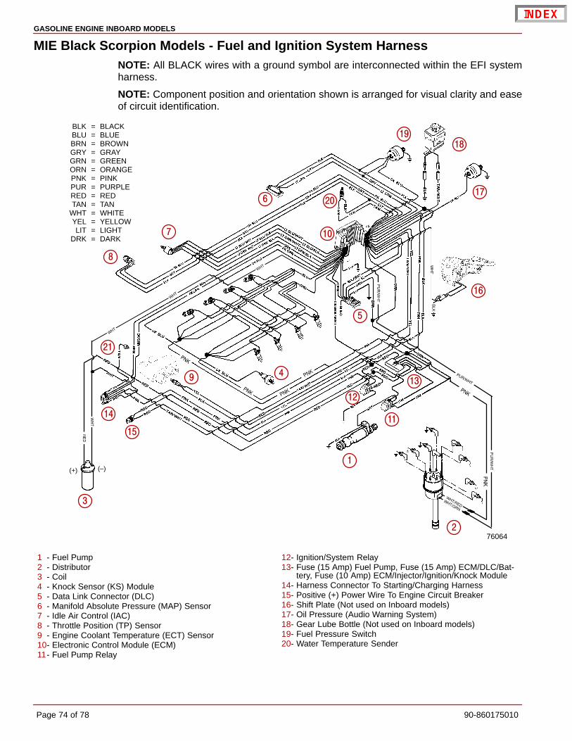
GASOLINE ENGINE INBOARD MODELS
Page 74 of 78 90-860175010
MIE Black Scorpion Models - Fuel and Ignition System HarnessNOTE: All BLACK wires with a ground symbol are interconnected within the EFI systemharness.
NOTE: Component position and orientation shown is arranged for visual clarity and easeof circuit identification.
(–)(+)
76064
BLK = BLACKBLU = BLUEBRN = BROWNGRY = GRAYGRN = GREENORN = ORANGEPNK = PINKPUR = PURPLERED = REDTAN = TAN
WHT = WHITEYEL = YELLOWLIT = LIGHT
DRK = DARK
�
�
�
�
�
�
�
�
��
��
��
��
��
��
�
��
��
�
�
��
1 - Fuel Pump2 - Distributor3 - Coil4 - Knock Sensor (KS) Module5 - Data Link Connector (DLC)6 - Manifold Absolute Pressure (MAP) Sensor7 - Idle Air Control (IAC)8 - Throttle Position (TP) Sensor9 - Engine Coolant Temperature (ECT) Sensor10- Electronic Control Module (ECM)11- Fuel Pump Relay
12- Ignition/System Relay13- Fuse (15 Amp) Fuel Pump, Fuse (15 Amp) ECM/DLC/Bat-
tery, Fuse (10 Amp) ECM/Injector/Ignition/Knock Module14- Harness Connector To Starting/Charging Harness15- Positive (+) Power Wire To Engine Circuit Breaker16- Shift Plate (Not used on Inboard models)17- Oil Pressure (Audio Warning System)18- Gear Lube Bottle (Not used on Inboard models)19- Fuel Pressure Switch20- Water Temperature Sender

GASOLINE ENGINE INBOARD MODELS
90-860175010 Page 75 of 78
MIE Water Flow Diagrams
Gasoline Engines with Seawater (Raw-Water) Cooling SystemNOTE: Certain components in the following diagram may look different than on yourparticular power package, but the water flow paths remain similar on all engines.
75149
�
�
�
�
�
�
�
�
�
��
1 - Seawater Intake2 - Seawater Pump3 - Transmission Cooler4 - Fuel Cooler (EFI Models)5 - Thermostat Housing and Cover Assembly6 - Engine Water Circulating Pump7 - Engine Block and Cylinder Head Assembly8 - Exhaust Manifold, Typical9 - Restrictor Gasket10 - Exhaust Elbow Assembly, Typical11 - Water Flow Overboard
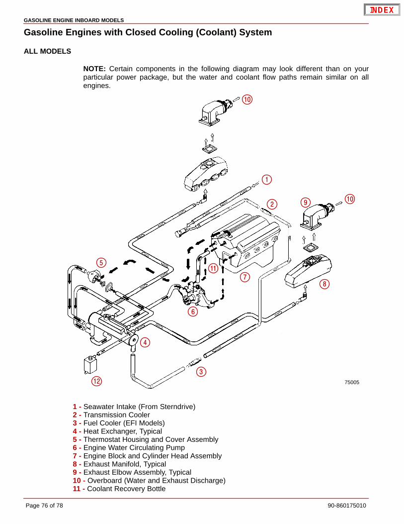
GASOLINE ENGINE INBOARD MODELS
Page 76 of 78 90-860175010
Gasoline Engines with Closed Cooling (Coolant) System
ALL MODELS
NOTE: Certain components in the following diagram may look different than on yourparticular power package, but the water and coolant flow paths remain similar on allengines.
75005
�
�
�
�
�
�
�
�
�
��
��
�
1 - Seawater Intake (From Sterndrive)2 - Transmission Cooler3 - Fuel Cooler (EFI Models)4 - Heat Exchanger, Typical5 - Thermostat Housing and Cover Assembly6 - Engine Water Circulating Pump7 - Engine Block and Cylinder Head Assembly8 - Exhaust Manifold, Typical9 - Exhaust Elbow Assembly, Typical10 - Overboard (Water and Exhaust Discharge)11 - Coolant Recovery Bottle

GASOLINE ENGINE INBOARD MODELS
90-860175010 Page 77 of 78
THIS PAGE IS INTENTIONALLY BLANK

GASOLINE ENGINE INBOARD MODELS
Page 78 of 78 90-860175010
Predelivery InspectionNot Check/Applicable Adjust
Not Check/Applicable Adjust
CHECK BEFORE RUNNING ON THE WATER TESTDrain plug in and petcocks Engine alignment (Inboards only)closed
Seawater inlet valve open Starter neutral safety switch operation
Engine mounts tightWater pump operation
Engine alignmentInstruments(s) operation
Drive unit fasteners torquedFuel leaks
Power trim cylinders fastenerstight Oil leaksBattery fully charged and secured
Water leaksAll electrical connections tight
Exhaust leaksExhaust system hose clampstight Ignition timingAll fuel connections tight
Idle RPM, within specificationsCorrect rotation propeller(installed and torqued)Throttle, shift and steering system Forward - Neutral - Reversefasteners tightened properly gear operationThrottle plates open and close Steering operation throughoutcompletely rangeCrankcase oil level Acceleration from idle rpm
Power trim oil level WOT RPM withinspecifications (in forward gear)
Stern drive unit oil levelPower trim operation
Power steering fluid levelTrim tab adjustment
Closed cooling levelBoat handling
Transmission fluid levelAFTER ON WATER TEST
Alternator belt tensionPropeller nut torque
Seawater pickup pump belttension
Fuel, oil, coolant, water and fluidPower steering pump belt tension leaks
Audio warning system operation Oil and fluid levels
Apply Quicksilver Corrosion Guard toengine package