gasoline engine inboard models installation manual · pdf filegasoline engine inboard models...
TRANSCRIPT
90-860175001 JANUARY 2001 Printed in U.S.A. - 2001, Mercury Marine Page 1 of 77
The following are registered trademarks ofBrunswick Corporation: Merc, MerCathode,MerCruiser, Mercury, Mercury Marine,Quicksilver, and RideGuide.
GASOLINE ENGINE INBOARD MODELSINSTALLATION MANUAL
NOTICE to INSTALLER
After Completing Installation, These Instructions Should Be Placed With The Product For The Own-er’s Future Use.
NOTICE to COMMISSIONING DEALER
Predelivery Preparation Instructions Must Be Performed Before Delivering Boat To The ProductOwner.
Table of Contents
General Information 2. . . . . . . . . . . . . . . . . . . . . . . Notice to Installer 2. . . . . . . . . . . . . . . . . . . . . . . . Quicksilver Products 3. . . . . . . . . . . . . . . . . . . . . Installation Products 3. . . . . . . . . . . . . . . . . . . . . Torque Specifications 3. . . . . . . . . . . . . . . . . . . . Serial Number Decal Placement 3. . . . . . . . . . . Engine Rotation 4. . . . . . . . . . . . . . . . . . . . . . . . .
Transmissions 4. . . . . . . . . . . . . . . . . . . . . . . . . . . . Identification 4. . . . . . . . . . . . . . . . . . . . . . . . . . . . Propeller Rotation 6. . . . . . . . . . . . . . . . . . . . . . .
Installation Requirements 9. . . . . . . . . . . . . . . . . Engine Bed 9. . . . . . . . . . . . . . . . . . . . . . . . . . . . . Engine Compartment 9. . . . . . . . . . . . . . . . . . . . Engine Compartment Ventilation 9. . . . . . . . . . . Exhaust System 12. . . . . . . . . . . . . . . . . . . . . . . . Fuel Delivery System 15. . . . . . . . . . . . . . . . . . . Battery 17. . . . . . . . . . . . . . . . . . . . . . . . . . . . . . . . EFI Electrical System Precautions 19. . . . . . . . Instrumentation 19. . . . . . . . . . . . . . . . . . . . . . . . . Propeller Selection 20. . . . . . . . . . . . . . . . . . . . . . Throttle/Shift Remote Control and Cables 21. . Seawater Connections 21. . . . . . . . . . . . . . . . . . Hot Water Heater Installation Information 22. .
Engine Installation 25. . . . . . . . . . . . . . . . . . . . . . . Engine Preparation 25. . . . . . . . . . . . . . . . . . . . . Battery Cable Connection 25. . . . . . . . . . . . . . . . Engine Mount Pre-Adjustment 26. . . . . . . . . . . . Initial Engine Alignment 27. . . . . . . . . . . . . . . . . Final Engine Alignment 29. . . . . . . . . . . . . . . . . . Closed Cooling Recovery Bottle 34. . . . . . . . . .
Engine Connections 36. . . . . . . . . . . . . . . . . . . . . . Seawater Pickup Pump Connection 36. . . . . . . Fuel Supply Connection 37. . . . . . . . . . . . . . . . . Audio Warning System 38. . . . . . . . . . . . . . . . . . Electrical Connections 39. . . . . . . . . . . . . . . . . . . Alternator Connection (Some Models) 39. . . . . Exhaust System Hose / Tube Connections 40.
Throttle Cable Installation and Adjustment 41. Carbureted Models 41. . . . . . . . . . . . . . . . . . . . . EFI Models 42. . . . . . . . . . . . . . . . . . . . . . . . . . . .
Shift Cable Installation And Adjustment 43. . . Velvet Drive Transmissions 43. . . . . . . . . . . . . . Hurth Transmissions 51. . . . . . . . . . . . . . . . . . . .
Predelivery Preparation 56. . . . . . . . . . . . . . . . . . . Battery Connection 56. . . . . . . . . . . . . . . . . . . . . Test Running Engine 56. . . . . . . . . . . . . . . . . . . . Boat-In-The-Water Tests 57. . . . . . . . . . . . . . . . . Cold Weather and Extended Storage Draining Instructions 58. . . . . . . . . . . . . . . . . . . . Closed Cooled (Coolant) Models 64. . . . . . . . .
Quicksilver Instrumentation Wiring Diagrams 66. . . . . . . . . . . . . . . . . . . . . . . . . . . . . . . MIE Gasoline Engine Wiring Diagrams 68. . . . . MIE Water Flow Diagrams 75. . . . . . . . . . . . . . . . . Predelivery Inspection 77. . . . . . . . . . . . . . . . . . . .
GASOLINE ENGINE INBOARD MODELS
Page 2 of 77
General Information
Notice to InstallerThroughout this publication, “Warnings” and “Cautions” (accompanied by the InternationalHazard Symbol ! ) are used to alert the installer to special instructions concerning aparticular service or operation that may be hazardous if performed incorrectly or carelessly.–– Observe Them Carefully!
These “Safety Alerts,” alone, cannot eliminate the hazards that they signal. Strictcompliance to these special instructions when performing the service, plus “commonsense” operation, are major accident prevention measures.
WARNINGHazards or unsafe practices which COULD result in severe personal injury or death.
CAUTIONHazards or unsafe practices which could result in minor personal injury or productor property damage.
IMPORTANT: Indicates information or instructions that are necessary for proper in-stallation and/or operation.
This installation manual has been written and published by Mercury Marine to aid the boatmanufacturer involved in the application and installation of the products described herein.
It is assumed that these personnel are familiar with the installation procedures of theseproducts, or like or similar products manufactured and marketed by Mercury Marine. Thatthey have been trained in the recommended installation procedures of these products whichincludes the use of mechanics’ common hand tools and the special Mercury Marine orrecommended tools from other suppliers.
It is the responsibility of the OEM to select the appropriate engine/transom/drive package(including the correct gear ratio and propeller) for a given boat. Making an appropriateselection requires knowledge of the boat (weight, length, hull design, intended use and dutycycle, desired speed, etc.) that is uniquely in the possession of the OEM. While Mercuryemploys people capable of assisting the OEM on such issues, the final decision rests withthe OEM. Mercury recommends that any new or unique hull/power package combinationbe thoroughly water tested prior to sale, to verify (among other things) that the boat performsas desired, and that the engine runs in the appropriate rpm range.
We could not possibly know of and advise the marine trade of all conceivable proceduresby which an installation might be performed, and of the possible hazards and/or results ofeach method. We have not undertaken any such wide evaluation. Therefore, anyone whouses an installation procedure and/or tool, which is not recommended by the manufacturer,first must completely satisfy himself that neither his nor the product’s safety will beendangered by the installation procedure selected.
It is recommended that a Mercury Marine Sales Application Engineer be contacted forassistance if specific application or installation problems are encountered.
All information, illustrations, and specifications contained in this manual are based on thelatest product information available at time of publication. As required, revisions to thismanual will be sent to all OEM boat companies.
GASOLINE ENGINE INBOARD MODELS
Page 3 of 77
Quicksilver ProductsQuicksilver gauges, remote controls, steering systems, propeller shaft couplers, etc. areavailable for this product. Refer to “Quicksilver Accessories Guide” for complete listing.
This “Guide” is available from:
Attn: Parts DepartmentMercury Marine
W6250 W. Pioneer RoadP.O. Box 1939
Fond du Lac, WI 54936-1939
Outside of U.S.A., order through Distribution Center, or Distributor.
Lubricants / Sealants / Adhesives
Description Part Number
Quicksilver 2-4-C Marine Lubricant with Teflon 92-825407A3
Quicksilver Liquid Neoprene 92-25711--3
Quicksilver Perfect Seal 92-34227--1
Torque Specifications
DESCRIPTION lb-in. lb-ft Nm
Engine Mount Bracket Screws 47 64
Trunnion Clamping Screw and Nut 50 68
Propeller Shaft Nut 50 68
Exhaust Manifold Screw 20 27
Fuel Line Inlet Fitting See Note.
Coupler Bolts 50 68
Note: Refer to Fuel Delivery System - “Special Information For All Gasoline Engines.”
Serial Number Decal PlacementThere are three engine serial number decal strips provided with each power package. Oneshould be used for each of the following:
• Engine Specification Decal
• Warranty Registration Card
• Operation and Maintenance Manual identification page.
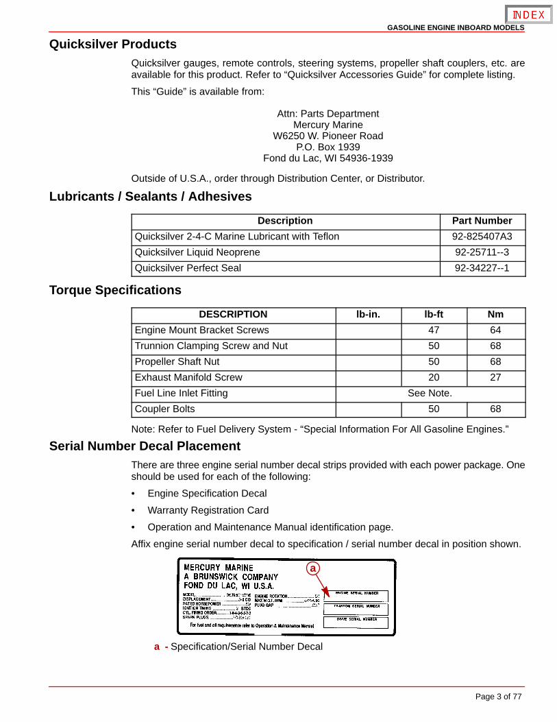
Affix engine serial number decal to specification / serial number decal in position shown.
a
a - Specification/Serial Number Decal
GASOLINE ENGINE INBOARD MODELS
Page 4 of 77
Engine RotationEngine rotation is described when observed from the rear of the engine (transmission end)looking forward (water pump end).
Engine rotation is indicated on engine specifications and serial number decal.
Transmissions
Identification
VELVET DRIVE TRANSMISSIONS
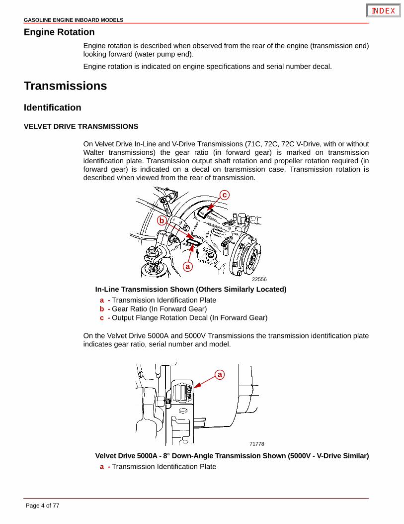
On Velvet Drive In-Line and V-Drive Transmissions (71C, 72C, 72C V-Drive, with or withoutWalter transmissions) the gear ratio (in forward gear) is marked on transmissionidentification plate. Transmission output shaft rotation and propeller rotation required (inforward gear) is indicated on a decal on transmission case. Transmission rotation isdescribed when viewed from the rear of transmission.
22556
a
b
c
In-Line Transmission Shown (Others Similarly Located)a - Transmission Identification Plateb - Gear Ratio (In Forward Gear)c - Output Flange Rotation Decal (In Forward Gear)
On the Velvet Drive 5000A and 5000V Transmissions the transmission identification plateindicates gear ratio, serial number and model.
71778
a
Velvet Drive 5000A - 8° Down-Angle Transmission Shown (5000V - V-Drive Similar)a - Transmission Identification Plate
GASOLINE ENGINE INBOARD MODELS
Page 5 of 77
ZF / HURTH TRANSMISSIONS
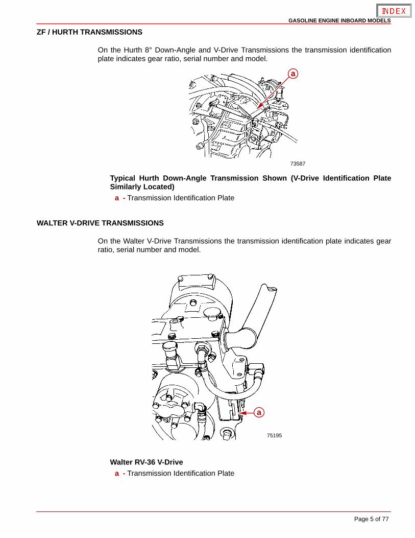
On the Hurth 8° Down-Angle and V-Drive Transmissions the transmission identificationplate indicates gear ratio, serial number and model.
73587
a
Typical Hurth Down-Angle Transmission Shown (V-Drive Identification PlateSimilarly Located)
a - Transmission Identification Plate
WALTER V-DRIVE TRANSMISSIONS
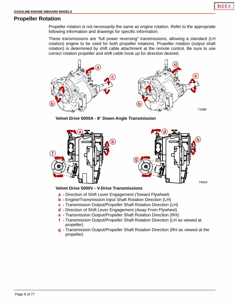
On the Walter V-Drive Transmissions the transmission identification plate indicates gearratio, serial number and model.
75195
a
Walter RV-36 V-Drivea - Transmission Identification Plate
GASOLINE ENGINE INBOARD MODELS
Page 6 of 77
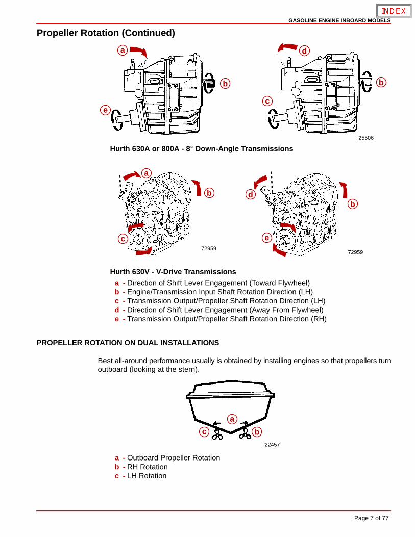
Propeller RotationPropeller rotation is not necessarily the same as engine rotation. Refer to the appropriatefollowing information and drawings for specific information.
These transmissions are “full power reversing” transmissions, allowing a standard (LHrotation) engine to be used for both propeller rotations. Propeller rotation (output shaftrotation) is determined by shift cable attachment at the remote control. Be sure to usecorrect rotation propeller and shift cable hook up for direction desired.
a
b
c
b71888
d
e
Velvet Drive 5000A - 8° Down-Angle Transmission
a
b
f
74604
b
g
d
Velvet Drive 5000V - V-Drive Transmissionsa - Direction of Shift Lever Engagement (Toward Flywheel)b - Engine/Transmission Input Shaft Rotation Direction (LH)c - Transmission Output/Propeller Shaft Rotation Direction (LH)d - Direction of Shift Lever Engagement (Away From Flywheel)e - Transmission Output/Propeller Shaft Rotation Direction (RH)f - Transmission Output/Propeller Shaft Rotation Direction (LH as viewed at
propeller)g - Transmission Output/Propeller Shaft Rotation Direction (RH as viewed at the
propeller)
GASOLINE ENGINE INBOARD MODELS
Page 7 of 77
Propeller Rotation (Continued)
c
25506
a
b
d
e
b
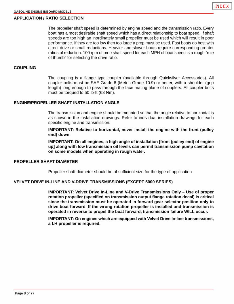
Hurth 630A or 800A - 8° Down-Angle Transmissions
7295972959
a
b
c
d
e
b
Hurth 630V - V-Drive Transmissionsa - Direction of Shift Lever Engagement (Toward Flywheel)b - Engine/Transmission Input Shaft Rotation Direction (LH)c - Transmission Output/Propeller Shaft Rotation Direction (LH)d - Direction of Shift Lever Engagement (Away From Flywheel)e - Transmission Output/Propeller Shaft Rotation Direction (RH)
PROPELLER ROTATION ON DUAL INSTALLATIONS
Best all-around performance usually is obtained by installing engines so that propellers turnoutboard (looking at the stern).
22457
a
c b
a - Outboard Propeller Rotationb - RH Rotationc - LH Rotation
GASOLINE ENGINE INBOARD MODELS
Page 8 of 77
APPLICATION / RATIO SELECTION
The propeller shaft speed is determined by engine speed and the transmission ratio. Everyboat has a most desirable shaft speed which has a direct relationship to boat speed. If shaftspeeds are too high an inordinately small propeller must be used which will result in poorperformance. If they are too low then too large a prop must be used. Fast boats do best withdirect drive or small reductions. Heavier and slower boats require corresponding greaterratios of reduction. 100 rpm of prop shaft speed for each MPH of boat speed is a rough “ruleof thumb” for selecting the drive ratio.
COUPLING
The coupling is a flange type coupler (available through Quicksilver Accessories). Allcoupler bolts must be SAE Grade 8 (Metric Grade 10.9) or better, with a shoulder (griplength) long enough to pass through the face mating plane of couplers. All coupler boltsmust be torqued to 50 lb-ft (68 Nm).
ENGINE/PROPELLER SHAFT INSTALLATION ANGLE
The transmission and engine should be mounted so that the angle relative to horizontal isas shown in the installation drawings. Refer to individual installation drawings for eachspecific engine and transmission.
IMPORTANT: Relative to horizontal, never install the engine with the front (pulleyend) down.
IMPORTANT: On all engines, a high angle of installation [front (pulley end) of engineup] along with low transmission oil levels can permit transmission pump cavitationon some models when operating in rough water.
PROPELLER SHAFT DIAMETER
Propeller shaft diameter should be of sufficient size for the type of application.
VELVET DRIVE IN-LINE AND V-DRIVE TRANSMISSIONS (EXCEPT 5000 SERIES)
IMPORTANT: Velvet Drive In-Line and V-Drive Transmissions Only – Use of properrotation propeller (specified on transmission output flange rotation decal) is criticalsince the transmission must be operated in forward gear selector position only todrive boat forward. If the wrong rotation propeller is installed and transmission isoperated in reverse to propel the boat forward, transmission failure WILL occur.
IMPORTANT: On engines which are equipped with Velvet Drive In-line transmissions,a LH propeller is required.

GASOLINE ENGINE INBOARD MODELS
Page 9 of 77
Installation Requirements
Engine BedDistance between starboard and port engine mount is 22-1/2 in. (572 mm). Engine bed mustposition engine so that a minimum of 1/4 in. (6 mm) up and down adjustment still exists onall 4 mounts after performing final engine alignment. This is necessary to allow for realigningengine in the future.
NOTE: Although the engine mounts allow some adjustment, it is a good practice to ensurethat the front and rear mount locations in the vessel are in parallel planes. This may bechecked by tying a string from the left front mount location to the right rear mount locationand another from right front to left rear. The strings should touch where they cross.
Engine Compartment
WARNINGBoating standards (NMMA, ABYC, etc.) and Coast Guard regulations must be ad-hered to when constructing the engine compartment.
Care must be exercised in the design and construction of the engine compartment. Seamsmust be located so that any rain water that may leak through the seams, is directed awayfrom the air intake system.
CAUTIONWater that runs onto the air intake may enter the engine and cause serious damageto internal engine parts.
Over the last several years, engine compartments have been designed to be quieter. Themost common material used to deaden the engine sound is some type of insulation material.Normally, the quieter the engine compartment is, the more insulation material used whichresults in less air space inside. The less air space inside the engine compartment, the hotterthe inside air temperature. Attention must be given to the air temperature that is inside thisengine compartment while the engine is running or after a period of time after the engineis shut off (heat soak). Refer to the following information on Engine CompartmentVentilation.
Engine Compartment VentilationAccording to Boating standards (NMMA, ABYC, and others) and Coast Guard regulationsthe engine compartment ventilation system has multiple tasks. Included are the following:
• To supply the engine with combustion air.
• To maintain a low temperature in the engine compartment.
Fresh air should enter the engine compartment as low as possible and the heated air shouldbe discharged from the highest point.
When sufficient ventilation is not provided, too much heat can build-up inside of enginecompartment and cause vapor locking. The engine will not want to restart after it has beenshut off for a short period of time. If it does restart, the engine will quit when given the throttleto get the boat up on plane or to pull up a water skier.
For engines utilizing fuels containing alcohol and the newer “reformulated gasolines” (SeeOEM Service Bulletin 95-2) proper ventilation is more critical to prevent vapor locking.
If a separate air shaft (or similar) is used to provide engine compartment ventilation oradditional ventilation, care must be taken to prevent seawater and spray from entering it.
GASOLINE ENGINE INBOARD MODELS
Page 10 of 77
COMBUSTION AIR REQUIREMENTS
Engine compartments with natural draft ventilation must have vent openings of sufficientsize and location to accomplish the tasks previously outlined.
IMPORTANT: The size of ventilation openings must be increased if any auxiliaryequipment is located in the engine compartment.
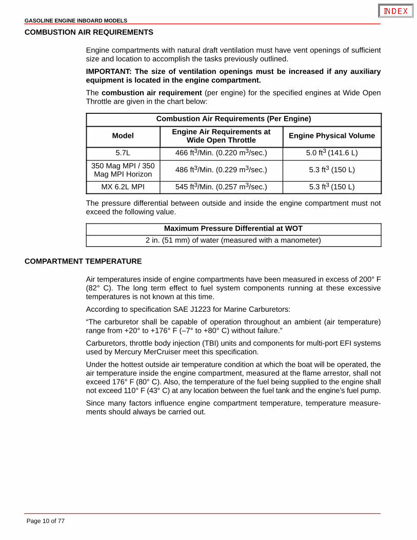
The combustion air requirement (per engine) for the specified engines at Wide OpenThrottle are given in the chart below:
Combustion Air Requirements (Per Engine)
Model Engine Air Requirements atWide Open Throttle Engine Physical Volume
5.7L 466 ft3/Min. (0.220 m3/sec.) 5.0 ft3 (141.6 L)
350 Mag MPI / 350Mag MPI Horizon
486 ft3/Min. (0.229 m3/sec.) 5.3 ft3 (150 L)
MX 6.2L MPI 545 ft3/Min. (0.257 m3/sec.) 5.3 ft3 (150 L)
The pressure differential between outside and inside the engine compartment must notexceed the following value.
Maximum Pressure Differential at WOT
2 in. (51 mm) of water (measured with a manometer)
COMPARTMENT TEMPERATURE
Air temperatures inside of engine compartments have been measured in excess of 200° F(82° C). The long term effect to fuel system components running at these excessivetemperatures is not known at this time.
According to specification SAE J1223 for Marine Carburetors:
“The carburetor shall be capable of operation throughout an ambient (air temperature)range from +20° to +176° F (–7° to +80° C) without failure.”
Carburetors, throttle body injection (TBI) units and components for multi-port EFI systemsused by Mercury MerCruiser meet this specification.
Under the hottest outside air temperature condition at which the boat will be operated, theair temperature inside the engine compartment, measured at the flame arrestor, shall notexceed 176° F (80° C). Also, the temperature of the fuel being supplied to the engine shallnot exceed 110° F (43° C) at any location between the fuel tank and the engine’s fuel pump.
Since many factors influence engine compartment temperature, temperature measure-ments should always be carried out.
GASOLINE ENGINE INBOARD MODELS
Page 11 of 77
Compartment Temperature -Testing
NOTE: The boat being tested shall be a standard production boat fitted as it would be fordelivery to a dealer.
NOTE: Temperature test meter used shall be of the type that can be read without openingthe engine cover.
IMPORTANT: During the test, engine compartments are to remain closed. No outsideair is to be forced into the engine compartment during the test and the bilge blowershould not be running.
1. Engine Running and Heat Soak Test:
a. Use 1 meter and 2-3 thermocouples. Place one thermocouple at the flame arrestorto measure the inlet air temperature.
b. Place the second thermocouple at the fuel pump to measure the inlet fuel tempera-ture.
c. A third thermocouple is needed if the fuel supply line between the tank and the fuelpump is higher than the fuel pump. Place the third thermocouple at the highest pointof the supply line to measure the temperature of the fuel at that point.
2. Start engine and operate until engine is at normal operating temperature.
3. Operate engine at 1500 rpm (in NEUTRAL gear) for 15 minutes. Record temperaturereadings at 5 minute intervals.
4. After 15 minutes at 1500 rpm, shut off engine and continue to record temperaturereadings at 5 minute intervals for the next 45 minutes.
5. After the 45 minute heat soak test, start engine and idle (in NEUTRAL gear) for 20minutes. Continue to record temperature readings at 5 minute intervals.
IMPORTANT: If the temperature at any location exceeds specifications, the enginecompartment will need additional ventilation until temperatures remain below thesespecifications.
GASOLINE ENGINE INBOARD MODELS
Page 12 of 77
Exhaust SystemIMPORTANT: It is the responsibility of the boat manufacturer or installing dealer toproperly locate the engine and install the exhaust system. Improper installation mayallow water to enter the exhaust manifolds and combustion chambers and severelydamage the engine. Damage caused by water in the engine will not be covered byMercury MerCruiser Warranty, unless this damage is the result of defective part(s).
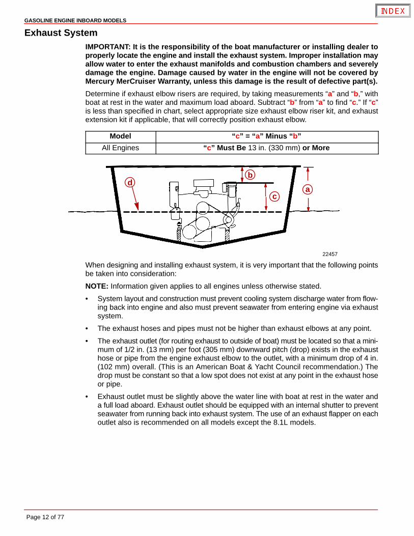
Determine if exhaust elbow risers are required, by taking measurements “a” and “b,” withboat at rest in the water and maximum load aboard. Subtract “b” from “a” to find “c.” If “c”is less than specified in chart, select appropriate size exhaust elbow riser kit, and exhaustextension kit if applicable, that will correctly position exhaust elbow.
Model “c” = “a” Minus “b”
All Engines “c” Must Be 13 in. (330 mm) or More
22457
db
ca
When designing and installing exhaust system, it is very important that the following pointsbe taken into consideration:
NOTE: Information given applies to all engines unless otherwise stated.
• System layout and construction must prevent cooling system discharge water from flow-ing back into engine and also must prevent seawater from entering engine via exhaustsystem.
• The exhaust hoses and pipes must not be higher than exhaust elbows at any point.
• The exhaust outlet (for routing exhaust to outside of boat) must be located so that a mini-mum of 1/2 in. (13 mm) per foot (305 mm) downward pitch (drop) exists in the exhausthose or pipe from the engine exhaust elbow to the outlet, with a minimum drop of 4 in.(102 mm) overall. (This is an American Boat & Yacht Council recommendation.) Thedrop must be constant so that a low spot does not exist at any point in the exhaust hoseor pipe.
• Exhaust outlet must be slightly above the water line with boat at rest in the water anda full load aboard. Exhaust outlet should be equipped with an internal shutter to preventseawater from running back into exhaust system. The use of an exhaust flapper on eachoutlet also is recommended on all models except the 8.1L models.
GASOLINE ENGINE INBOARD MODELS
Page 13 of 77
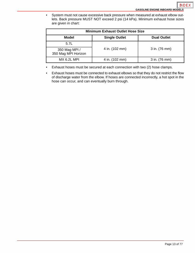
• System must not cause excessive back pressure when measured at exhaust elbow out-lets. Back pressure MUST NOT exceed 2 psi (14 kPa). Minimum exhaust hose sizesare given in chart:
Minimum Exhaust Outlet Hose Size
Model Single Outlet Dual Outlet
5.7L
350 Mag MPI /350 Mag MPI Horizon
4 in. (102 mm) 3 in. (76 mm)
MX 6.2L MPI 4 in. (102 mm) 3 in. (76 mm)
• Exhaust hoses must be secured at each connection with two (2) hose clamps.
• Exhaust hoses must be connected to exhaust elbows so that they do not restrict the flowof discharge water from the elbow. If hoses are connected incorrectly, a hot spot in thehose can occur, and can eventually burn through.
GASOLINE ENGINE INBOARD MODELS
Page 14 of 77
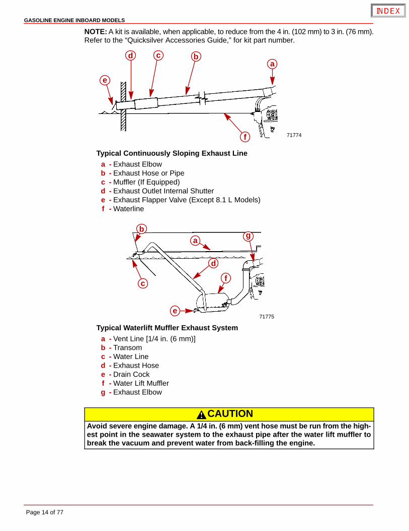
NOTE: A kit is available, when applicable, to reduce from the 4 in. (102 mm) to 3 in. (76 mm).Refer to the “Quicksilver Accessories Guide,” for kit part number.
71774
abcd
e
f
Typical Continuously Sloping Exhaust Linea - Exhaust Elbowb - Exhaust Hose or Pipec - Muffler (If Equipped)d - Exhaust Outlet Internal Shuttere - Exhaust Flapper Valve (Except 8.1 L Models)f - Waterline
71775
ab
c
d
e
f
g
Typical Waterlift Muffler Exhaust Systema - Vent Line [1/4 in. (6 mm)]b - Transomc - Water Lined - Exhaust Hosee - Drain Cockf - Water Lift Mufflerg - Exhaust Elbow
CAUTIONAvoid severe engine damage. A 1/4 in. (6 mm) vent hose must be run from the high-est point in the seawater system to the exhaust pipe after the water lift muffler tobreak the vacuum and prevent water from back-filling the engine.

GASOLINE ENGINE INBOARD MODELS
Page 15 of 77
Fuel Delivery System
WARNINGBoating standards (NMMA, ABYC, etc.) and Coast Guard regulations must beadhered to when installing fuel delivery system.
GENERAL
The main concern of a boat’s fuel system is safety; this must be achieved through atechnically sound installation and constant inspection.
The fuel system, from the filler pipe to the fuel pump is the same, in principle, for all boats.
The Fuel Tank is an integrated component of the boat. Refer to the special information onservice and maintenance, which you have received from the tank manufacturer.
Only a few points related to function and safety are listed here [Refer to boating standards(NMMA, ABYC, etc.) and Coast Guard regulations for complete guidelines]:
• All connections should be on the upper side of the tank.
• The drain plug at the lowest point on the tank serves to permit the removal of water andsediment.
• The tank breather pipe must have an inner diameter of at least 1/2 in. (13 mm) and mustbe fitted with a swan neck to prevent water from entering the tank.
It is recommended that the exact route and length of the fuel lines be established at the firstinstallation of the engine to prevent problems later in connecting them to the engine.
All fuel lines must be well secured. The holes where the lines run through the bulkheadsshould be carefully rounded off, or protected with rubber grommets. This prevents damageto the lines from abrasion.
The following, but not limited to the following, additional fuel connection related points,applying to all engines unless otherwise stated, must be considered [Refer to boatingstandards (NMMA, ABYC, etc.) and Coast Guard regulations for complete guidelines]:
1. Fuel tank should be mounted below carburetor level (if possible) or gravity feed maycause carburetor fuel inlet needle to unseat, and flooding may result.
2. On Gasoline Engines: The maximum measured vacuum at the engine’s fuel inlet mustnot exceed 2 in. Hg (6.9 kPa) at 600, 3000, full throttle rpm and back at idle rpm.
IMPORTANT: Vacuum reading higher than specified can cause vapor locking withsome of today’s fuels. It can also cause poor engine performance because of fuelstarvation.
3. Fuel pickup should be at least 1 in. (25 mm) from the bottom of fuel tank, to prevent pick-ing up impurities.
4. Fuel lines used must be Coast Guard approved (USCG Type A1).
Diameter of fittings and lines must not be smaller than 5/16 in. (8 mm) I.D. on 350 cid / 5.7Lengines.
Diameter of fittings and lines must not be smaller than 3/8 in. (10 mm) I.D. on 377 cid / 6.2L.
5. On Multi-Engine Installations: It is best to use a fuel pickup and supply line for eachengine. If a single pickup and line is used, fittings and line must not be smaller than 1/2in. (13 mm) I.D.
6. Larger diameter (than previously specified) lines, and fittings must be used on installa-tions requiring long lines or numerous fittings.
GASOLINE ENGINE INBOARD MODELS
Page 16 of 77
7. Fuel line(s) should be installed free of stress and firmly secured to prevent vibration and/or chafing.
8. Sharp bends in fuel lines should be avoided.
9. A flexible fuel line must be used to connect fuel supply line to fuel inlet fitting on engine,to absorb deflection when engine is running.
SPECIAL INFORMATION ABOUT ELECTRIC FUEL PUMPS
CAUTIONThe electric fuel pump and factory installed water separating fuel filter have beencarefully designed to function properly together. Do not install additional fuel filtersand/or water separating fuel filters between fuel tank and engine.
The installation of additional filters may cause:
• Fuel Vapor Locking
• Difficult Warm-Starting
• Piston Detonation Due to Lean Fuel Mixture
• Poor Driveability
SPECIAL INFORMATION FOR ALL GASOLINE ENGINES
WARNINGAvoid gasoline fire or explosion. Improper installation of brass fittings or plugs intofuel pump or fuel filter base can crack casting and/or cause a fuel leak.
IMPORTANT: The following information is provided to ensure proper installation ofbrass fittings or plugs installed into fuel pump or fuel filter base:
• Use #592 Loctite Pipe Sealant with Teflon on threads of brass fittings or plugs. DONOT USE TEFLON TAPE.
• Brass fittings or plugs should first be threaded into fuel pump or fuel filter baseuntil finger tight.
• Fittings or plugs should then be tighten an additional 1-3/4 to 2-1/4 turns usinga wrench. DO NOT OVERTIGHTEN.
• To prevent overtightening when installing a fuel line, the brass fittings should beheld with a suitable wrench as fuel line connectors are tightened securely.

GASOLINE ENGINE INBOARD MODELS
Page 17 of 77
BatteryIMPORTANT: Boating industry standards (BIA, ABYC, etc.), federal standards andCoast Guard regulations must be adhered to when installing battery. Be sure batterycable installation meets the pull test requirements and that positive battery terminalis properly insulated in accordance with regulations.
IMPORTANT: Engine electrical system is negative (–) ground. It is recommended(required in some states) that battery be installed in an enclosed case. Refer toregulations for your area.
Select a battery that meets all of the following specifications:
1. 12-volt marine type.
2. Tapered post connector or side terminal connectors. Do not use a battery with wing nutconnectors.
3. Reserve battery capacity rating of at least:
GASOLINE ENGINES
Engine (cyl./type) cid (L) Minimum Required CrankingBattery Size
V8 Carb 350 (5.7) 375 cca, 475 mca or 90 Ah
V8 MPI 350 (5.7) 377 (6.2) 550 cca, 700 mca or 120 Ah
MULTIPLE EFI ENGINE BATTERY PRECAUTIONS
Situation
Alternators: Alternators are designed to charge the battery that supplies electrical powerto the engine that the alternator is mounted on. When batteries for two different engines areconnected, one alternator will supply all of the charging current for both batteries. Normally,the other engine’s alternator will not be required to supply any charging current.
EFI Electronic Control Module (ECM): The ECM requires a stable voltage source. Duringmultiple engine operation, an onboard electrical device may cause a sudden drain of voltageat the engine’s battery. The voltage may go below the ECM’s minimum required voltage.Also, the alternator on the other engine may now start charging. This could cause a voltagespike in the engine’s electrical system.
In either case, the ECM could shut off. When the voltage returns to the range that the ECMrequires, the ECM will reset itself. The engine will now run normally. This ECM shut downusually happens so fast that the engine just appears to have an ignition miss.
Recommendations
Batteries: Boats with multi-engine EFI power packages require each engine be connectedto its own battery. This ensures that the engine’s Electronic Control Module (ECM) has astable voltage source.
Battery Switches: Battery switches should always be positioned so each engine is runningoff its own battery. DO NOT operate engines with switches in BOTH or ALL position. In anemergency, another engine’s battery can be used to start an engine with a dead battery.

GASOLINE ENGINE INBOARD MODELS
Page 18 of 77
Battery Isolators: Isolators can be used to charge an auxiliary battery used for poweringaccessories in the boat. They should not be used to charge the battery of another enginein the boat unless the type of isolator is specifically designed for this purpose.
NOTE: Sure Power Industries Inc., Model 32023A meets this design specification.
1. The boat may have 2 engines connected to a single Model 32023A battery isolator.
2. The Model 32023A battery isolator is connected to 2 banks of batteries.
3. Each bank contains 2 batteries with the cranking battery for 1 engine in each bank.
4. The second battery in each bank is connected in parallel to the cranking battery.
5. The Model 32023A battery isolator is designed for this type of use; 2 battery banks, 2charging sources, 120 amps (maximum alternator output).
6. When the engines are running, either engine’s alternator could be charging either bankof batteries through the Model 32023A battery isolator.
Any other manufacturer’s battery isolator that is the same type as the Sure Power Inc.,Model 32023A could also be used.
Generators: The generator’s battery should be considered another engine’s battery.
BATTERY CABLES
Select proper size positive (+) and negative (–) battery cables, using chart. Battery shouldbe located as close to engine as possible.
IMPORTANT: Terminals must be soldered to cable ends to ensure good electricalcontact. Use electrical grade (resin flux) solder only. Do not use acid flux solder asit may cause corrosion and a subsequent failure.
GASOLINE ENGINES
Cable Length Cable Gauge
Up to 3-1/2 ft (1.1 m) 4 (25 mm2)
3-1/2 - 6 ft (1.1-1.8 m) 2 (35 mm2)
6 - 7-1/2 ft (1.8-2.3 m) 1 (50 mm2)
7-1/2 - 9-1/2 ft (2.3-2.9 m) 0 (50 mm2)
9-1/2 - 12 ft (2.9-3.7 m) 00 (70 mm2)
12 - 15 ft (3.7-4.6 m) 000 (95 mm2)
15 - 19 ft (4.6-5.8 m) 0000 (120 mm2)
GASOLINE ENGINE INBOARD MODELS
Page 19 of 77
EFI Electrical System PrecautionsNOTE: All references to EFI models apply to EFI and MPI Engines. The following precau-tions apply to all EFI models.
CAUTIONAvoid damage to the EFI electrical system and components. Refer to the followingprecautions when working on or around the EFI electrical harness or when addingother electrical accessories:
• DO NOT tap accessories into engine harness.
• DO NOT puncture wires for testing (Probing).
• DO NOT reverse battery leads.
• DO NOT splice wires into harness.
• DO NOT attempt diagnostics without proper, approved Service Tools.
Instrumentation
GASOLINE ENGINES
CAUTIONIf Quicksilver wiring harness is used, and a fused accessory panel is to be installed(40-amp current draw maximum), be sure to connect it as shown in wiring diagram.Do not connect accessory panel at any other location, as wires in wiring harnessmay not be of sufficient size to handle current load.
We recommend the use of Quicksilver Instrumentation and Wiring harness(es). On dualstation applications, oil pressure and water temperature senders (on engine) must bechanged. Refer to “Quicksilver Accessories Guide” for selection.
The 4 basic gauges, which must be used with the engine, are:
• Tachometer
• Oil Pressure
• Water Temperature
• Voltmeter
Route instrumentation wiring harness back to engine, making sure that harness does notrub or get pinched. If an extension harness is required, be sure to secure connectionproperly. Fasten harness(es) to boat at least every 18 in. (460 mm), using appropriatefasteners.
GASOLINE ENGINE INBOARD MODELS
Page 20 of 77
Propeller SelectionIMPORTANT: Installed propeller must allow engine to run at its specified maximumWOT rpm. Use an accurate service tachometer to verify engine operating rpm.
It is the responsibility of the boat manufacturer and/or the selling dealer to equip the powerpackage with the correct propeller. Refer to Quicksilver publication - Everything You NeedTo Know About Propellers P/N 90-8614492. Specified engine WOT and operating rpmrange are listed in the Mercury MerCruiser Operation, Maintenance and Warranty Manualattached to the engine.
Select a propeller that will allow the engine power package to operate at or near the top endof the recommended wide-open-throttle operating rpm range with a normal load.
If full throttle operation is below the recommended range, the propeller must be changedto prevent loss of performance and possible engine damage. On the other hand, operatingan engine above the recommended operating rpm range will cause higher than normal wearand/or damage.
After initial propeller selection, the following common problems may require that thepropeller be changed to a lower pitch.
• Warmer weather and greater humidity cause a loss of rpm.
• Operating in a higher elevation causes a loss of rpm.
• Operating with increased load (additional passengers, pulling skiers) causes a loss ofrpm.
For better acceleration, such as is needed for water skiing, use the next lower pitchpropeller. Do not operate at full throttle when using the lower pitch propeller but not pullingskiers.
Because of the many variables of boat design, only testing will determine the best propellerfor a particular application. Available propellers are listed in the Quicksilver AccessoriesGuide.
See BOAT IN THE WATER TESTS, Maximum RPM Test at the back of this manual.
GASOLINE ENGINE INBOARD MODELS
Page 21 of 77
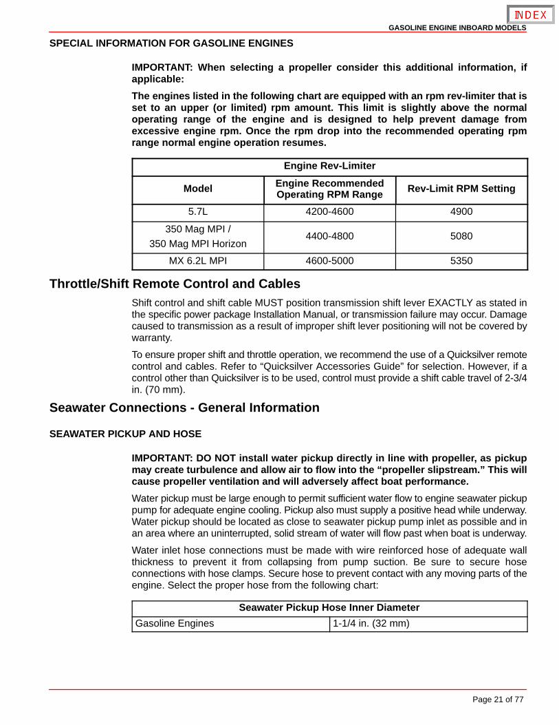
SPECIAL INFORMATION FOR GASOLINE ENGINES
IMPORTANT: When selecting a propeller consider this additional information, ifapplicable:
The engines listed in the following chart are equipped with an rpm rev-limiter that isset to an upper (or limited) rpm amount. This limit is slightly above the normaloperating range of the engine and is designed to help prevent damage fromexcessive engine rpm. Once the rpm drop into the recommended operating rpmrange normal engine operation resumes.
Engine Rev-Limiter
Model Engine RecommendedOperating RPM Range Rev-Limit RPM Setting
5.7L 4200-4600 4900
350 Mag MPI /
350 Mag MPI Horizon4400-4800 5080
MX 6.2L MPI 4600-5000 5350
Throttle/Shift Remote Control and CablesShift control and shift cable MUST position transmission shift lever EXACTLY as stated inthe specific power package Installation Manual, or transmission failure may occur. Damagecaused to transmission as a result of improper shift lever positioning will not be covered bywarranty.
To ensure proper shift and throttle operation, we recommend the use of a Quicksilver remotecontrol and cables. Refer to “Quicksilver Accessories Guide” for selection. However, if acontrol other than Quicksilver is to be used, control must provide a shift cable travel of 2-3/4in. (70 mm).
Seawater Connections - General Information
SEAWATER PICKUP AND HOSE
IMPORTANT: DO NOT install water pickup directly in line with propeller, as pickupmay create turbulence and allow air to flow into the “propeller slipstream.” This willcause propeller ventilation and will adversely affect boat performance.
Water pickup must be large enough to permit sufficient water flow to engine seawater pickuppump for adequate engine cooling. Pickup also must supply a positive head while underway.Water pickup should be located as close to seawater pickup pump inlet as possible and inan area where an uninterrupted, solid stream of water will flow past when boat is underway.
Water inlet hose connections must be made with wire reinforced hose of adequate wallthickness to prevent it from collapsing from pump suction. Be sure to secure hoseconnections with hose clamps. Secure hose to prevent contact with any moving parts of theengine. Select the proper hose from the following chart:
Seawater Pickup Hose Inner Diameter
Gasoline Engines 1-1/4 in. (32 mm)
GASOLINE ENGINE INBOARD MODELS
Page 22 of 77
SEACOCK SIZE
Seacock used must have an internal cross-sectional area equal to or greater than seawaterhose to prevent restricting water flow. A brass ball or gate valve is required. Select a properseacock based on the following chart:
Seacock Size(Internal Cross-Sectional Area Equal to or Greater Than Size Shown)
Gasoline Engines 1-1/4 in. (32 mm)
Install the seacock in an area where it will be easily accessible and supported adequatelyto prevent hose fatigue.
SEA STRAINER
Strainer used must be of sufficient size to ensure that an adequate supply of water will bemaintained for cooling engine. Select a properly rated seawater strainer based on thefollowing chart:
Seawater Strainer Minimum Flow Rate 1
Gasoline Engines 30 (114)
1 Amounts listed are in U.S. gallons per minute and (liters per minute).
The seawater strainer should be installed in an area where it will be easily accessible forinspection and cleaning. The strainer should be installed in water inlet hose after theseacock (water inlet valve) to allow operator to shut off water when cleaning strainer.
Hot Water Heater Installation InformationIMPORTANT: When connecting a cabin heater or hot water heater, certain require-ments must be met, including, but not limited to the following:
• Supply hose (from engine to heater) and return hose (from heater to engine)MUST NOT EXCEED 5/8 in. (16 mm) I.D. (inside diameter).
• Make heater connections ONLY at locations indicated in the following informa-tion.
• Refer to manufacturers’ instructions for complete installation information andprocedures.
CAUTIONAvoid a performance loss and/or possible engine damage. Engine coolant mustflow continuously from the engine intake manifold to the engine water circulatingpump. NEVER close-off or block the coolant flow to or from a heater.All heater installations must be plumbed in series with the supply and return con-nections.
CAUTIONAvoid engine overheating which could result in engine damage. On modelsequipped with Closed Cooling, an air pocket may form in the closed cooling systemif some coolant is lost from the system and the cabin heater or hot water is mountedhigher than the fill cap on the heat exchanger. Heater must be mounted lower thanthe fill cap of the heat exchanger on models so equipped.
IMPORTANT: Do not reposition engine temperature switch; it must remain whereinstalled by factory.
GASOLINE ENGINE INBOARD MODELS
Page 23 of 77
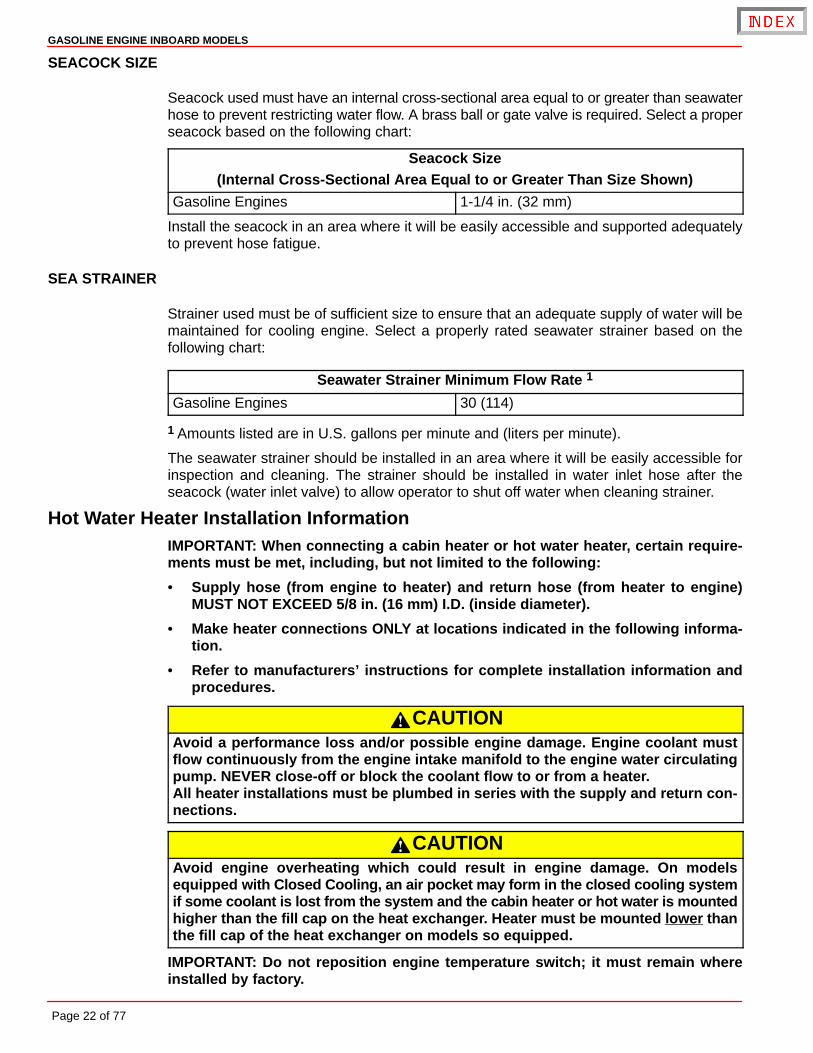
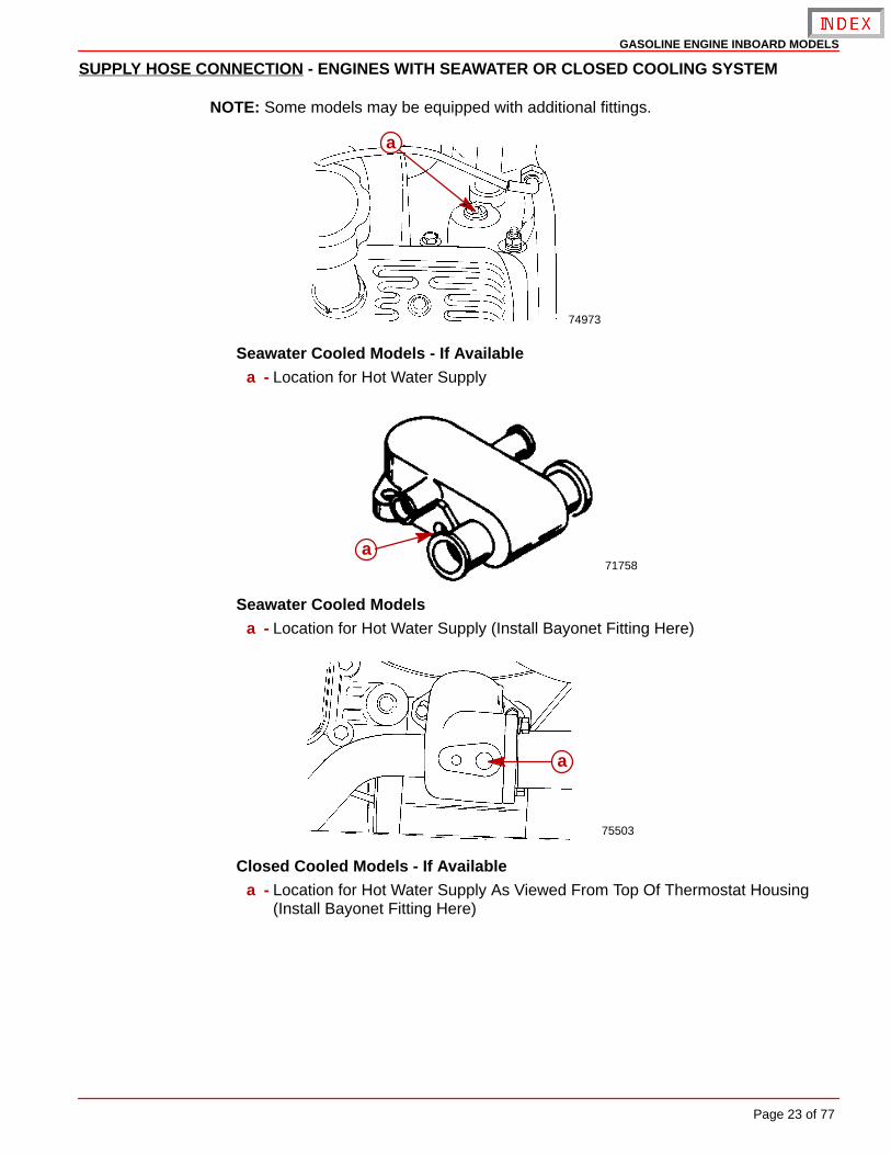
SUPPLY HOSE CONNECTION - ENGINES WITH SEAWATER OR CLOSED COOLING SYSTEM
NOTE: Some models may be equipped with additional fittings.
74973
a
Seawater Cooled Models - If Availablea - Location for Hot Water Supply
71758a
Seawater Cooled Modelsa - Location for Hot Water Supply (Install Bayonet Fitting Here)
75503
a
Closed Cooled Models - If Availablea - Location for Hot Water Supply As Viewed From Top Of Thermostat Housing
(Install Bayonet Fitting Here)
GASOLINE ENGINE INBOARD MODELS
Page 24 of 77
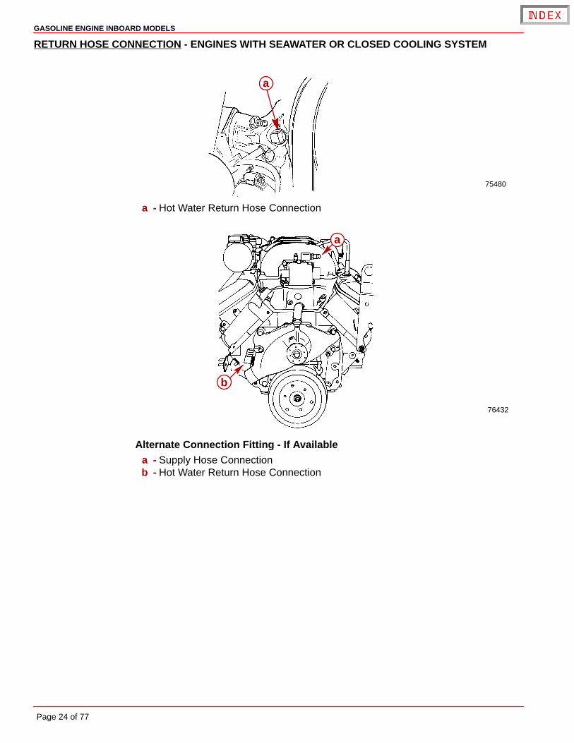
RETURN HOSE CONNECTION - ENGINES WITH SEAWATER OR CLOSED COOLING SYSTEM
75480
a
a - Hot Water Return Hose Connection
76432
a
b
Alternate Connection Fitting - If Availablea - Supply Hose Connectionb - Hot Water Return Hose Connection

GASOLINE ENGINE INBOARD MODELS
Page 25 of 77
Engine Installation
NOTICE to INSTALLER
Before Starting Installation read “General Information” and “Installation Require-ments” completely.
Engine Preparation
ENGINE OIL DIPSTICK RELOCATION (IF EQUIPPED)
Engine crankcase oil dipstick can be located on either starboard or port side of engine tosuit installation requirements. To move dipstick, remove dipstick from current location andinstall in opposite side. Place rubber cap over the open dipstick tube.
7638675425
b
a
a - Dipstick (Typical)b - Rubber Cap
Battery Cable ConnectionIMPORTANT: Engine electrical system is negative (–) ground.
IMPORTANT: Before connecting battery cables, make sure that grounding stud andstarter solenoid terminal are free of paint or any other material that could cause apoor electrical connection.
1. Connect negative (BLK) battery cable to grounding stud on flywheel housing and tightennut securely.
2. Connect positive (RED) battery cable to 10 mm terminal on starter solenoid and tightennut securely.
GASOLINE ENGINE INBOARD MODELS
Page 26 of 77
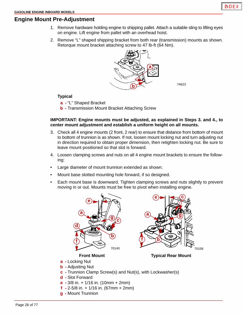
Engine Mount Pre-Adjustment1. Remove hardware holding engine to shipping pallet. Attach a suitable sling to lifting eyes
on engine. Lift engine from pallet with an overhead hoist.
2. Remove “L” shaped shipping bracket from both rear (transmission) mounts as shown.Retorque mount bracket attaching screw to 47 lb-ft (64 Nm).
74623
a
b
Typicala - “L” Shaped Bracketb - Transmission Mount Bracket Attaching Screw
IMPORTANT: Engine mounts must be adjusted, as explained in Steps 3. and 4., tocenter mount adjustment and establish a uniform height on all mounts.
3. Check all 4 engine mounts (2 front, 2 rear) to ensure that distance from bottom of mountto bottom of trunnion is as shown. If not, loosen mount locking nut and turn adjusting nutin direction required to obtain proper dimension, then retighten locking nut. Be sure toleave mount positioned so that slot is forward.
4. Loosen clamping screws and nuts on all 4 engine mount brackets to ensure the follow-ing:
• Large diameter of mount trunnion extended as shown.
• Mount base slotted mounting hole forward, if so designed.
• Each mount base is downward. Tighten clamping screws and nuts slightly to preventmoving in or out. Mounts must be free to pivot when installing engine.
70140 70158
a
e
d
fb
cg
a
b
ce
f
g
Front Mount Typical Rear Mounta - Locking Nutb - Adjusting Nutc - Trunnion Clamp Screw(s) and Nut(s), with Lockwasher(s)d - Slot Forwarde - 3/8 in. + 1/16 in. (10mm + 2mm)f - 2-5/8 in. + 1/16 in. (67mm + 2mm)g - Mount Trunnion
GASOLINE ENGINE INBOARD MODELS
Page 27 of 77
Initial Engine Alignment
MODELS WITH 8° DOWN ANGLE TRANSMISSIONS - VELVET DRIVE OR HURTH
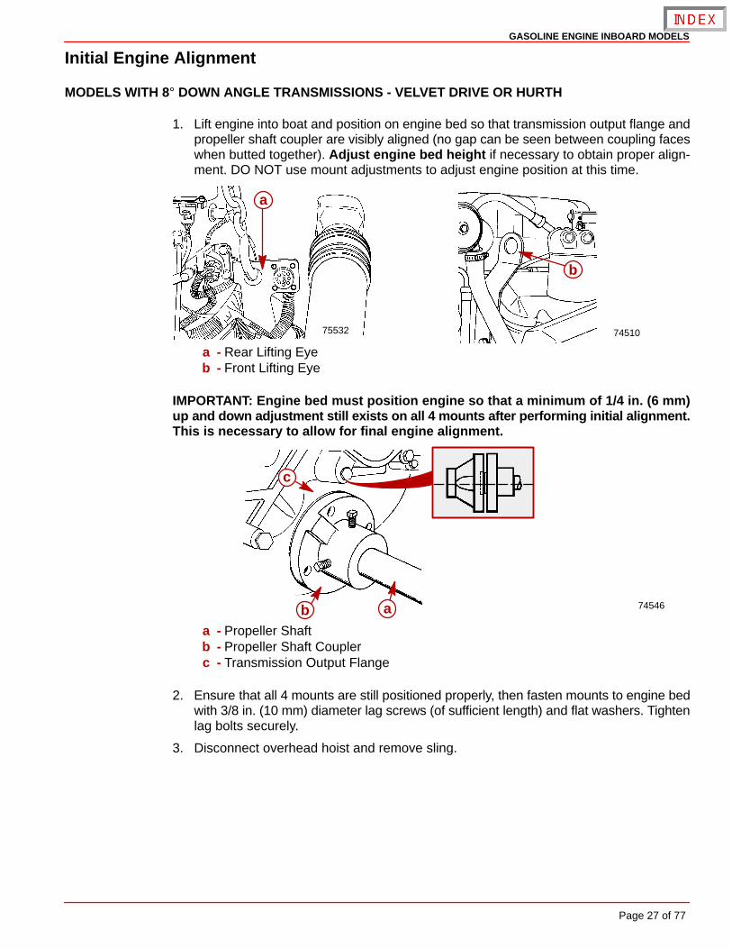
1. Lift engine into boat and position on engine bed so that transmission output flange andpropeller shaft coupler are visibly aligned (no gap can be seen between coupling faceswhen butted together). Adjust engine bed height if necessary to obtain proper align-ment. DO NOT use mount adjustments to adjust engine position at this time.
75532 74510
a
b
a - Rear Lifting Eyeb - Front Lifting Eye
IMPORTANT: Engine bed must position engine so that a minimum of 1/4 in. (6 mm)up and down adjustment still exists on all 4 mounts after performing initial alignment.This is necessary to allow for final engine alignment.
74546ab
c
a - Propeller Shaftb - Propeller Shaft Couplerc - Transmission Output Flange
2. Ensure that all 4 mounts are still positioned properly, then fasten mounts to engine bedwith 3/8 in. (10 mm) diameter lag screws (of sufficient length) and flat washers. Tightenlag bolts securely.
3. Disconnect overhead hoist and remove sling.
GASOLINE ENGINE INBOARD MODELS
Page 28 of 77
MODELS WITH V-DRIVE TRANSMISSIONS
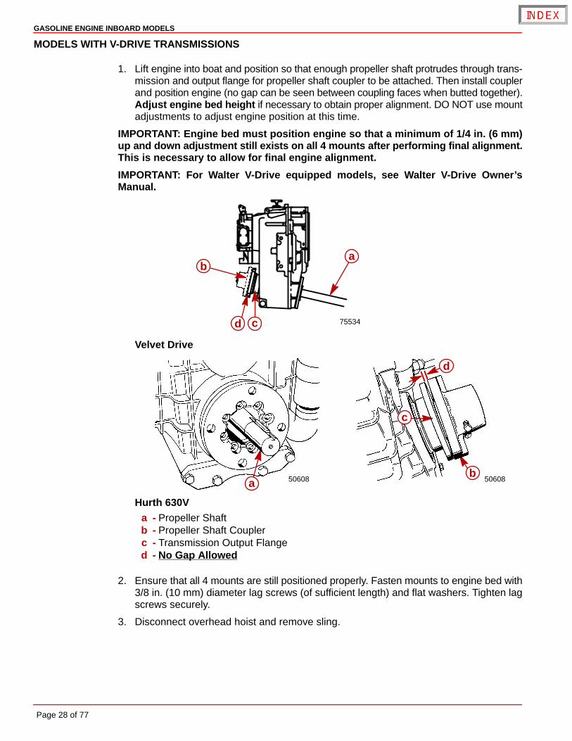
1. Lift engine into boat and position so that enough propeller shaft protrudes through trans-mission and output flange for propeller shaft coupler to be attached. Then install couplerand position engine (no gap can be seen between coupling faces when butted together).Adjust engine bed height if necessary to obtain proper alignment. DO NOT use mountadjustments to adjust engine position at this time.
IMPORTANT: Engine bed must position engine so that a minimum of 1/4 in. (6 mm)up and down adjustment still exists on all 4 mounts after performing final alignment.This is necessary to allow for final engine alignment.
IMPORTANT: For Walter V-Drive equipped models, see Walter V-Drive Owner’sManual.
75534
ab
cd
Velvet Drive
50608 50608ab
c
d
Hurth 630Va - Propeller Shaftb - Propeller Shaft Couplerc - Transmission Output Flanged - No Gap Allowed
2. Ensure that all 4 mounts are still positioned properly. Fasten mounts to engine bed with3/8 in. (10 mm) diameter lag screws (of sufficient length) and flat washers. Tighten lagscrews securely.
3. Disconnect overhead hoist and remove sling.
GASOLINE ENGINE INBOARD MODELS
Page 29 of 77
Final Engine AlignmentIMPORTANT: Engine alignment MUST BE RECHECKED with boat in the water, fueltanks filled and with a normal load on board.
Engine must be aligned so that transmission and propeller shaft coupling centerlines arealigned and coupling faces are parallel within .003 in. (0.07 mm). This applies to installationswith solid couplings as well as flexible couplings.
1. Check mating faces on transmission output flange and propeller shaft coupler to makesure they are clean and flat.
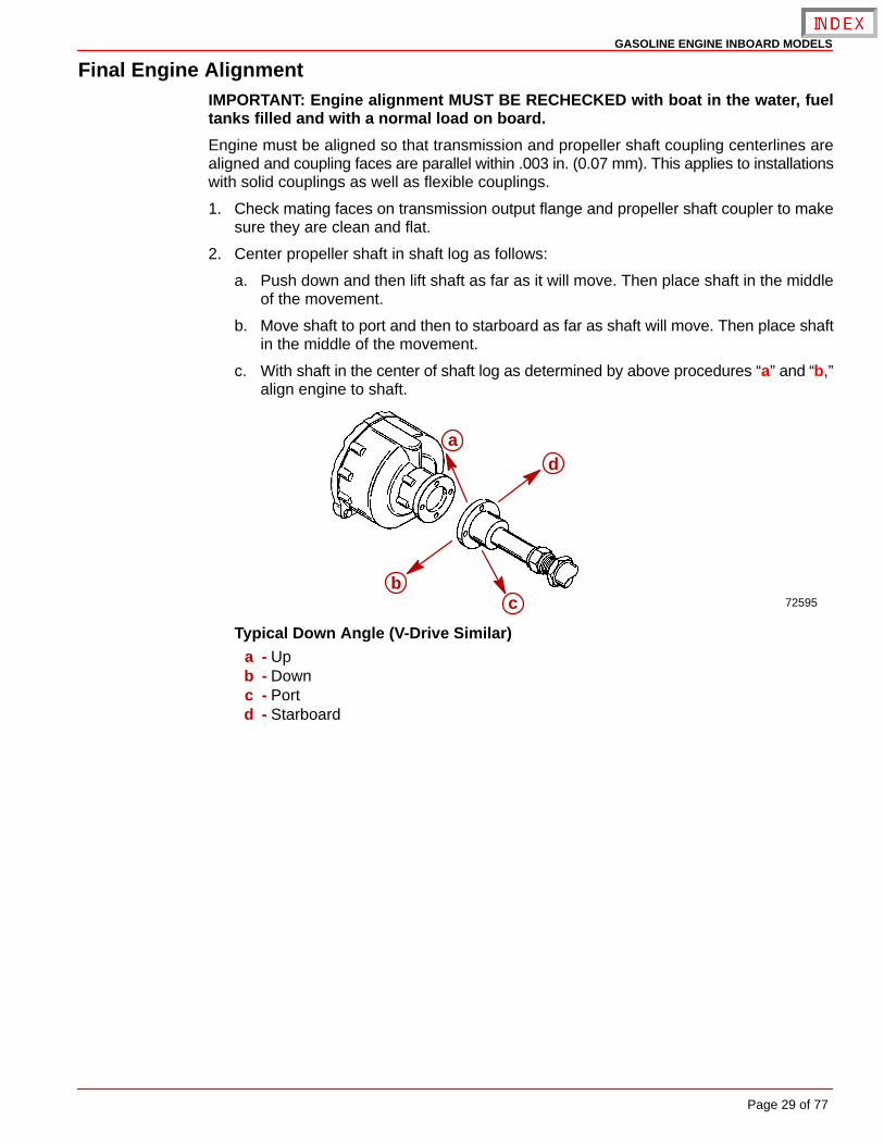
2. Center propeller shaft in shaft log as follows:
a. Push down and then lift shaft as far as it will move. Then place shaft in the middleof the movement.
b. Move shaft to port and then to starboard as far as shaft will move. Then place shaftin the middle of the movement.
c. With shaft in the center of shaft log as determined by above procedures “a” and “b,”align engine to shaft.
72595
ad
bc
Typical Down Angle (V-Drive Similar)a - Upb - Downc - Portd - Starboard
GASOLINE ENGINE INBOARD MODELS
Page 30 of 77
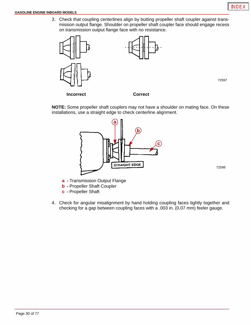
3. Check that coupling centerlines align by butting propeller shaft coupler against trans-mission output flange. Shoulder on propeller shaft coupler face should engage recesson transmission output flange face with no resistance.
72597
Incorrect Correct
NOTE: Some propeller shaft couplers may not have a shoulder on mating face. On theseinstallations, use a straight edge to check centerline alignment.
72598
a
b
c
a - Transmission Output Flangeb - Propeller Shaft Couplerc - Propeller Shaft
4. Check for angular misalignment by hand holding coupling faces tightly together andchecking for a gap between coupling faces with a .003 in. (0.07 mm) feeler gauge.
GASOLINE ENGINE INBOARD MODELS
Page 31 of 77
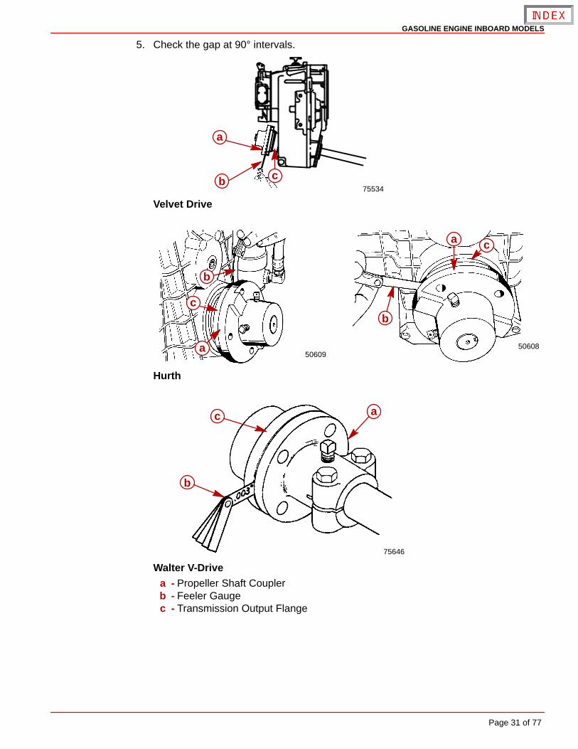
5. Check the gap at 90° intervals.
75534
a
b c
Velvet Drive
50608a
a
b
bc
c
50609
Hurth
75646
a
b
c
Walter V-Drivea - Propeller Shaft Couplerb - Feeler Gaugec - Transmission Output Flange
GASOLINE ENGINE INBOARD MODELS
Page 32 of 77
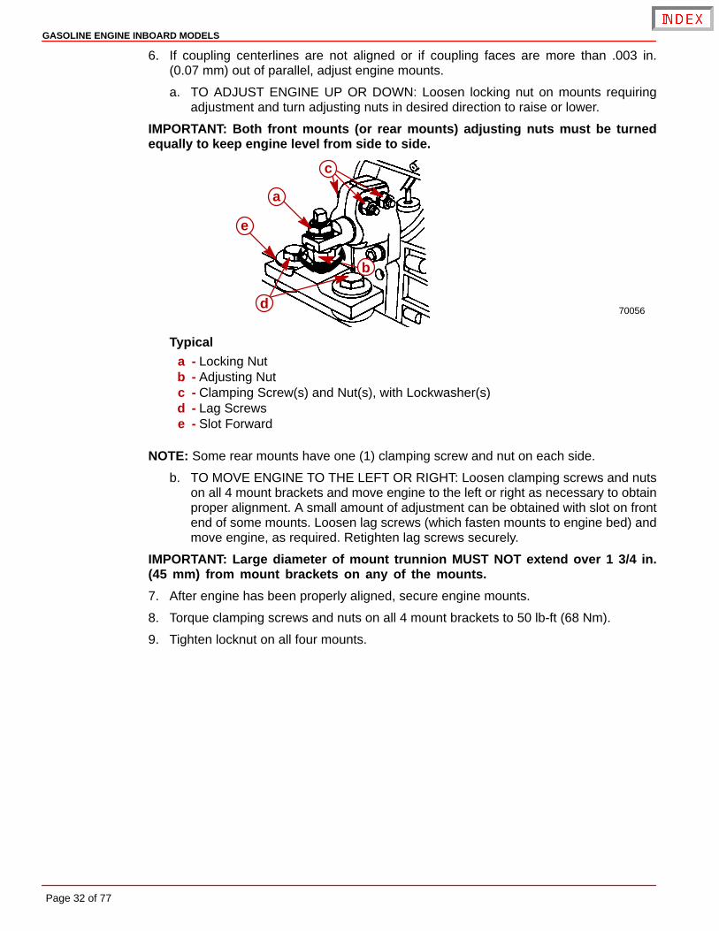
6. If coupling centerlines are not aligned or if coupling faces are more than .003 in.(0.07 mm) out of parallel, adjust engine mounts.
a. TO ADJUST ENGINE UP OR DOWN: Loosen locking nut on mounts requiringadjustment and turn adjusting nuts in desired direction to raise or lower.
IMPORTANT: Both front mounts (or rear mounts) adjusting nuts must be turnedequally to keep engine level from side to side.
70056
a
b
c
d
e
Typicala - Locking Nutb - Adjusting Nutc - Clamping Screw(s) and Nut(s), with Lockwasher(s)d - Lag Screwse - Slot Forward
NOTE: Some rear mounts have one (1) clamping screw and nut on each side.
b. TO MOVE ENGINE TO THE LEFT OR RIGHT: Loosen clamping screws and nutson all 4 mount brackets and move engine to the left or right as necessary to obtainproper alignment. A small amount of adjustment can be obtained with slot on frontend of some mounts. Loosen lag screws (which fasten mounts to engine bed) andmove engine, as required. Retighten lag screws securely.
IMPORTANT: Large diameter of mount trunnion MUST NOT extend over 1 3/4 in.(45 mm) from mount brackets on any of the mounts.
7. After engine has been properly aligned, secure engine mounts.
8. Torque clamping screws and nuts on all 4 mount brackets to 50 lb-ft (68 Nm).
9. Tighten locknut on all four mounts.
GASOLINE ENGINE INBOARD MODELS
Page 33 of 77
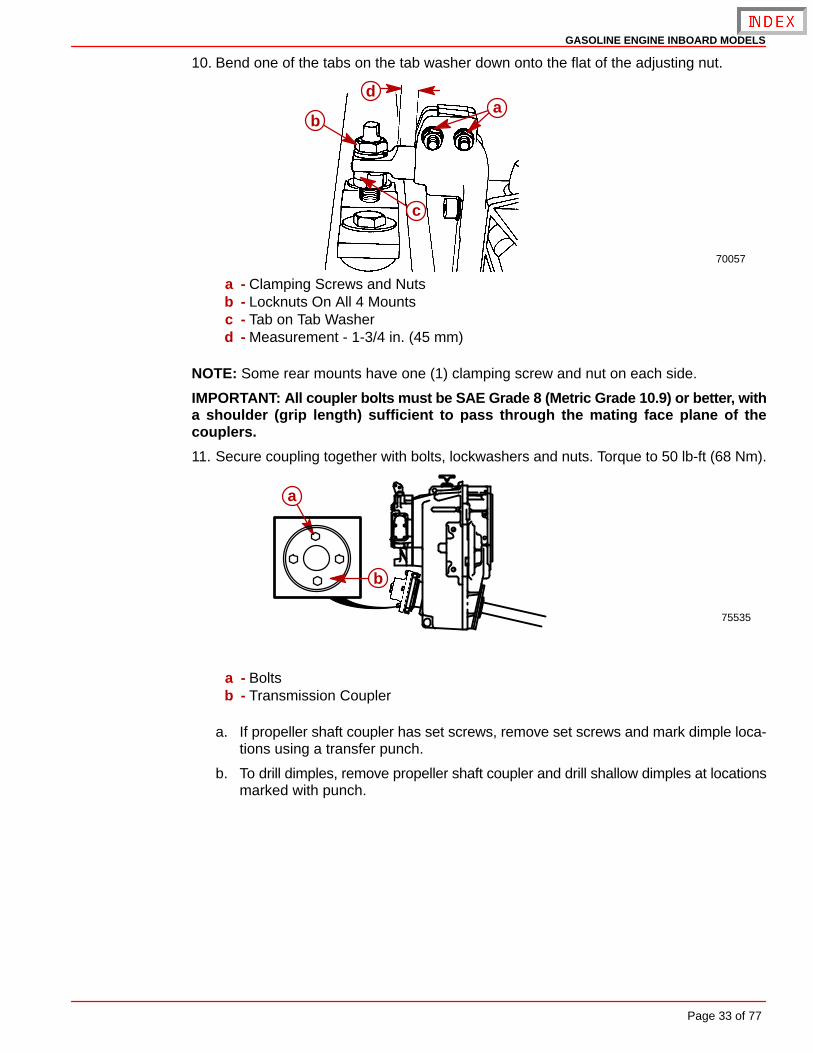
10. Bend one of the tabs on the tab washer down onto the flat of the adjusting nut.
70057
ab
c
d
a - Clamping Screws and Nutsb - Locknuts On All 4 Mountsc - Tab on Tab Washerd - Measurement - 1-3/4 in. (45 mm)
NOTE: Some rear mounts have one (1) clamping screw and nut on each side.
IMPORTANT: All coupler bolts must be SAE Grade 8 (Metric Grade 10.9) or better, witha shoulder (grip length) sufficient to pass through the mating face plane of thecouplers.
11. Secure coupling together with bolts, lockwashers and nuts. Torque to 50 lb-ft (68 Nm).
75535
a
b
a - Boltsb - Transmission Coupler
a. If propeller shaft coupler has set screws, remove set screws and mark dimple loca-tions using a transfer punch.
b. To drill dimples, remove propeller shaft coupler and drill shallow dimples at locationsmarked with punch.
GASOLINE ENGINE INBOARD MODELS
Page 34 of 77
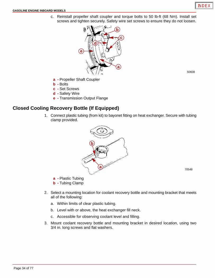
c. Reinstall propeller shaft coupler and torque bolts to 50 lb-ft (68 Nm). Install setscrews and tighten securely. Safety wire set screws to ensure they do not loosen.
50608
a
b
cd
e
a - Propeller Shaft Couplerb - Boltsc - Set Screwsd - Safety Wiree - Transmission Output Flange
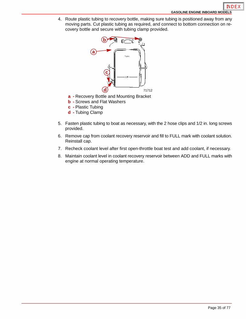
Closed Cooling Recovery Bottle (If Equipped)1. Connect plastic tubing (from kit) to bayonet fitting on heat exchanger. Secure with tubing
clamp provided.
70548a
b
a - Plastic Tubingb - Tubing Clamp
2. Select a mounting location for coolant recovery bottle and mounting bracket that meetsall of the following:
a. Within limits of clear plastic tubing.
b. Level with or above, the heat exchanger fill neck.
c. Accessible for observing coolant level and filling.
3. Mount coolant recovery bottle and mounting bracket in desired location, using two3/4 in. long screws and flat washers.
GASOLINE ENGINE INBOARD MODELS
Page 35 of 77
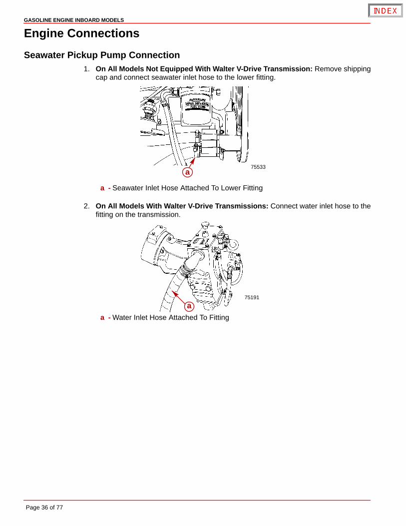
4. Route plastic tubing to recovery bottle, making sure tubing is positioned away from anymoving parts. Cut plastic tubing as required, and connect to bottom connection on re-covery bottle and secure with tubing clamp provided.
71712
a
b
c
da - Recovery Bottle and Mounting Bracketb - Screws and Flat Washersc - Plastic Tubingd - Tubing Clamp
5. Fasten plastic tubing to boat as necessary, with the 2 hose clips and 1/2 in. long screwsprovided.
6. Remove cap from coolant recovery reservoir and fill to FULL mark with coolant solution.Reinstall cap.
7. Recheck coolant level after first open-throttle boat test and add coolant, if necessary.
8. Maintain coolant level in coolant recovery reservoir between ADD and FULL marks withengine at normal operating temperature.
GASOLINE ENGINE INBOARD MODELS
Page 36 of 77
Engine Connections
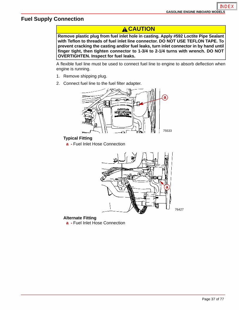
Seawater Pickup Pump Connection1. On All Models Not Equipped With Walter V-Drive Transmission: Remove shipping
cap and connect seawater inlet hose to the lower fitting.
75533a
a - Seawater Inlet Hose Attached To Lower Fitting
2. On All Models With Walter V-Drive Transmissions: Connect water inlet hose to thefitting on the transmission.
75191
aa - Water Inlet Hose Attached To Fitting
GASOLINE ENGINE INBOARD MODELS
Page 37 of 77
Fuel Supply Connection
CAUTIONRemove plastic plug from fuel inlet hole in casting. Apply #592 Loctite Pipe Sealantwith Teflon to threads of fuel inlet line connector. DO NOT USE TEFLON TAPE. Toprevent cracking the casting and/or fuel leaks, turn inlet connector in by hand untilfinger tight, then tighten connector to 1-3/4 to 2-1/4 turns with wrench. DO NOTOVERTIGHTEN. Inspect for fuel leaks.
A flexible fuel line must be used to connect fuel line to engine to absorb deflection whenengine is running.
1. Remove shipping plug.
2. Connect fuel line to the fuel filter adapter.
75533
a
Typical Fittinga - Fuel Inlet Hose Connection
76427
a
Alternate Fittinga - Fuel Inlet Hose Connection
GASOLINE ENGINE INBOARD MODELS
Page 38 of 77
Audio Warning System Connection
WARNINGBuzzer is not external ignition-proof, therefore, DO NOT mount horn in engine orfuel tank compartments.
1. Select a location for audio warning horn which meets all of the following:
• A location where horn can be easily heard, yet is out of sight.
• A location which is easily accessible for installation and maintenance.
• A location where horn will not get wet.
• A location close enough to one of the gauges so that the 18in. purple horn wire will con-nect to the “I” terminal or 12 volt source on switched side of ignition switch.
NOTE: The terminal to which wire is attached must have no voltage when ignition switchis in the OFF position.
2. Place horn in desired location. Secure horn to wire bundle with sta-strap provided.
3. Attach PURPLE wire from horn to any 12-volt source on switched side of ignition switch.Tighten connection securely, and coat with liquid neoprene.
4. Connect TAN/BLUE wire from the horn, to TAN/BLUE wire from instrument harness. Besure that bullet connector is tightly together.
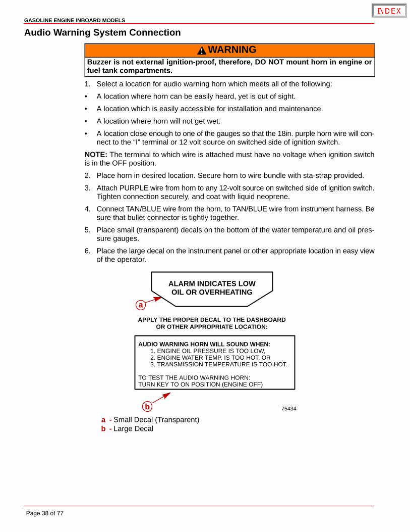
5. Place small (transparent) decals on the bottom of the water temperature and oil pres-sure gauges.
6. Place the large decal on the instrument panel or other appropriate location in easy viewof the operator.
75434
ALARM INDICATES LOWOIL OR OVERHEATING
APPLY THE PROPER DECAL TO THE DASHBOARDOR OTHER APPROPRIATE LOCATION:
AUDIO WARNING HORN WILL SOUND WHEN:1. ENGINE OIL PRESSURE IS TOO LOW,2. ENGINE WATER TEMP. IS TOO HOT, OR3. TRANSMISSION TEMPERATURE IS TOO HOT.
TO TEST THE AUDIO WARNING HORN:TURN KEY TO ON POSITION (ENGINE OFF)
a
b
a - Small Decal (Transparent)b - Large Decal
GASOLINE ENGINE INBOARD MODELS
Page 39 of 77
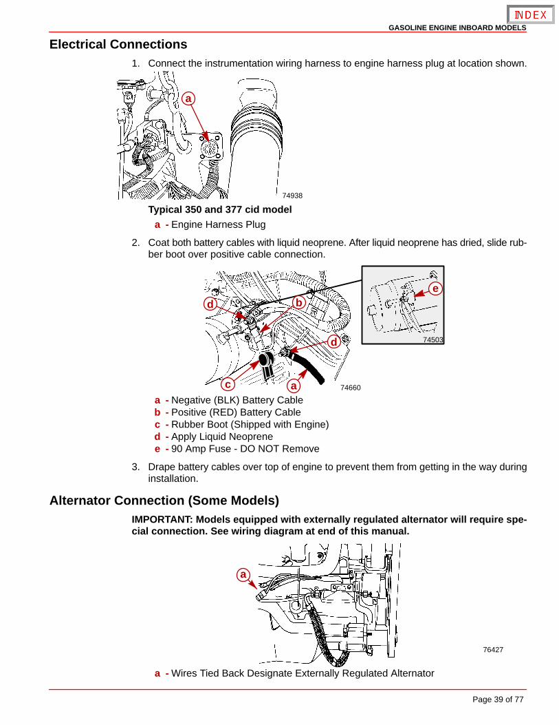
Electrical Connections1. Connect the instrumentation wiring harness to engine harness plug at location shown.
74938
a
Typical 350 and 377 cid modela - Engine Harness Plug
2. Coat both battery cables with liquid neoprene. After liquid neoprene has dried, slide rub-ber boot over positive cable connection.
74660
74503
c a
ed
d
b
a - Negative (BLK) Battery Cableb - Positive (RED) Battery Cablec - Rubber Boot (Shipped with Engine)d - Apply Liquid Neoprenee - 90 Amp Fuse - DO NOT Remove
3. Drape battery cables over top of engine to prevent them from getting in the way duringinstallation.
Alternator Connection (Some Models)IMPORTANT: Models equipped with externally regulated alternator will require spe-cial connection. See wiring diagram at end of this manual.
76427
a
a - Wires Tied Back Designate Externally Regulated Alternator
GASOLINE ENGINE INBOARD MODELS
Page 40 of 77
Exhaust System Hose / Tube Connections
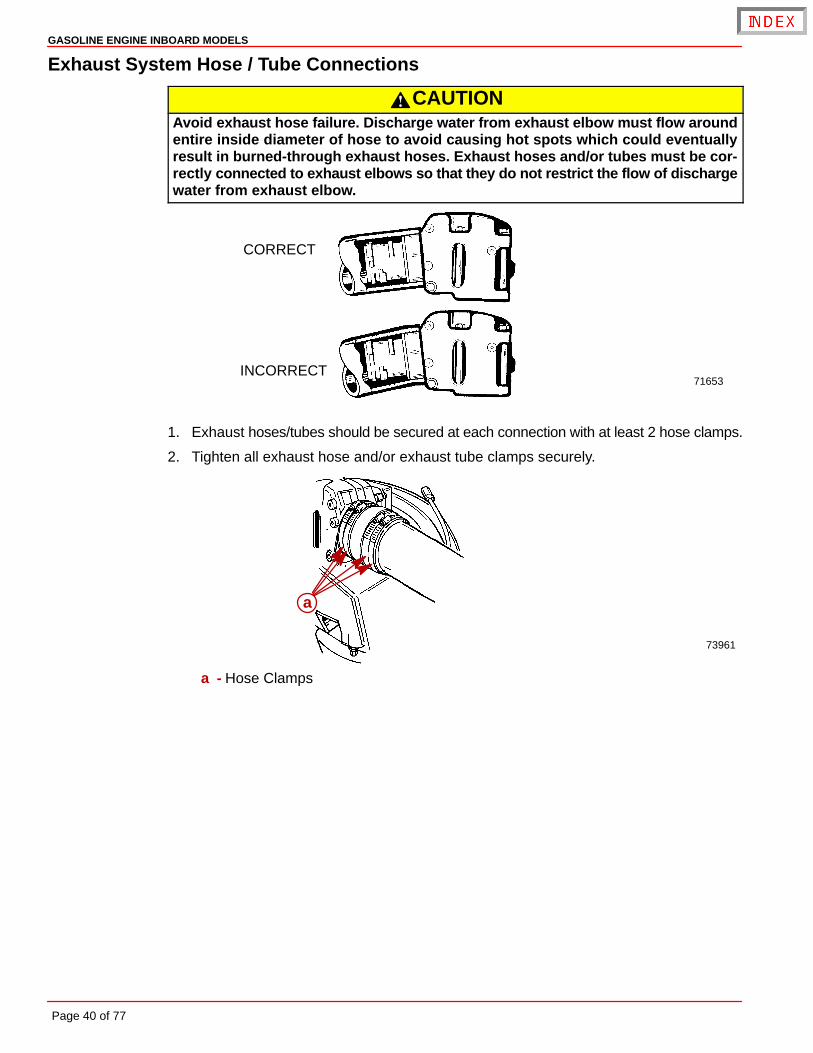
CAUTIONAvoid exhaust hose failure. Discharge water from exhaust elbow must flow aroundentire inside diameter of hose to avoid causing hot spots which could eventuallyresult in burned-through exhaust hoses. Exhaust hoses and/or tubes must be cor-rectly connected to exhaust elbows so that they do not restrict the flow of dischargewater from exhaust elbow.
71653
CORRECT
INCORRECT
1. Exhaust hoses/tubes should be secured at each connection with at least 2 hose clamps.
2. Tighten all exhaust hose and/or exhaust tube clamps securely.
73961
a
a - Hose Clamps
GASOLINE ENGINE INBOARD MODELS
Page 41 of 77
Throttle Cable Installation and AdjustmentCarbureted Models
IMPORTANT: When installing throttle cable, be sure that cables are routed in such away as to avoid sharp bends and/or contact with moving parts. DO NOT fasten anyitems to throttle cable.
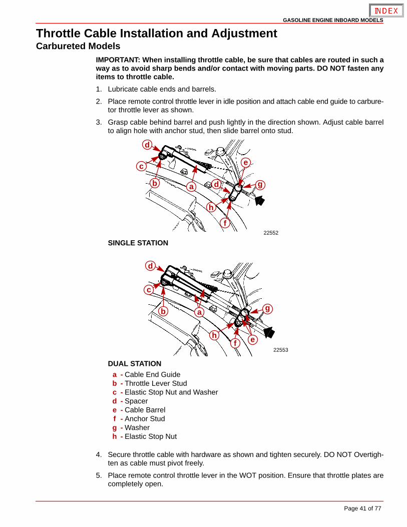
1. Lubricate cable ends and barrels.
2. Place remote control throttle lever in idle position and attach cable end guide to carbure-tor throttle lever as shown.
3. Grasp cable behind barrel and push lightly in the direction shown. Adjust cable barrelto align hole with anchor stud, then slide barrel onto stud.
22552
ab
c
d
d
e
f
g
h
SINGLE STATION
22553
ab
c
ef
d
h
g
DUAL STATIONa - Cable End Guideb - Throttle Lever Studc - Elastic Stop Nut and Washerd - Spacere - Cable Barrelf - Anchor Studg - Washerh - Elastic Stop Nut
4. Secure throttle cable with hardware as shown and tighten securely. DO NOT Overtigh-ten as cable must pivot freely.
5. Place remote control throttle lever in the WOT position. Ensure that throttle plates arecompletely open.
GASOLINE ENGINE INBOARD MODELS
Page 42 of 77
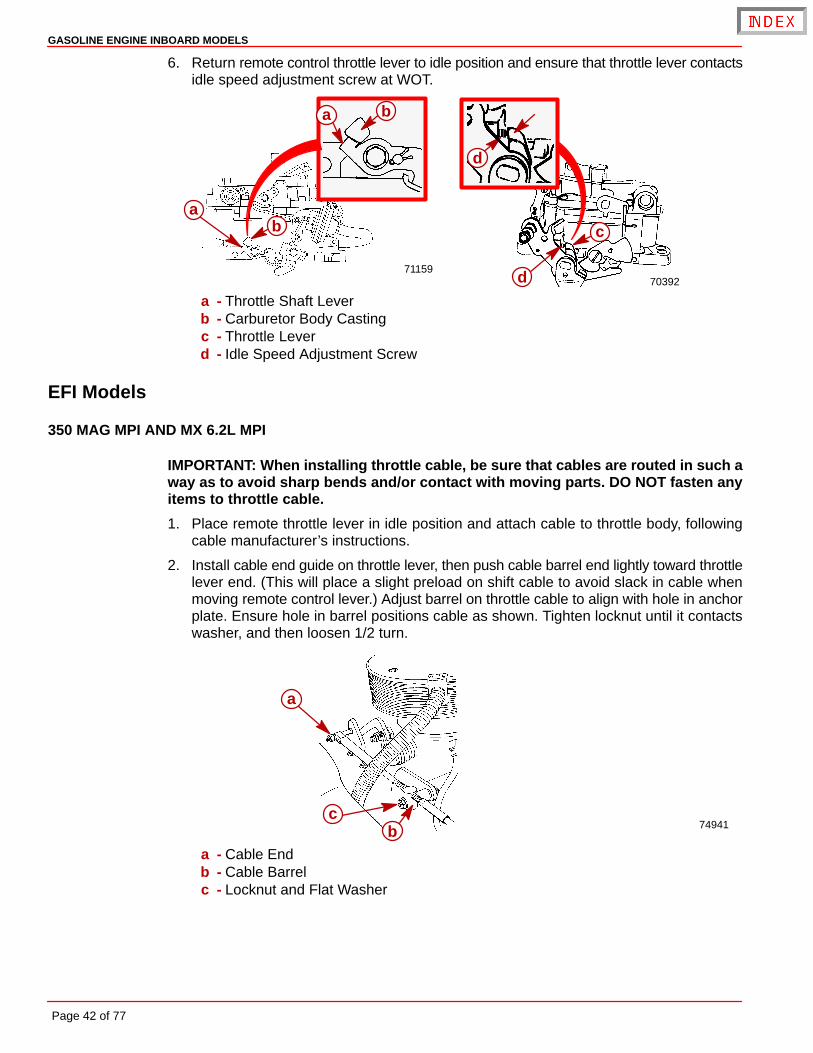
6. Return remote control throttle lever to idle position and ensure that throttle lever contactsidle speed adjustment screw at WOT.
7039271159
b
ab c
d
d
a
a - Throttle Shaft Leverb - Carburetor Body Castingc - Throttle Leverd - Idle Speed Adjustment Screw
EFI Models
350 MAG MPI AND MX 6.2L MPI
IMPORTANT: When installing throttle cable, be sure that cables are routed in such away as to avoid sharp bends and/or contact with moving parts. DO NOT fasten anyitems to throttle cable.
1. Place remote throttle lever in idle position and attach cable to throttle body, followingcable manufacturer’s instructions.
2. Install cable end guide on throttle lever, then push cable barrel end lightly toward throttlelever end. (This will place a slight preload on shift cable to avoid slack in cable whenmoving remote control lever.) Adjust barrel on throttle cable to align with hole in anchorplate. Ensure hole in barrel positions cable as shown. Tighten locknut until it contactswasher, and then loosen 1/2 turn.
74941
a
bc
a - Cable Endb - Cable Barrelc - Locknut and Flat Washer
GASOLINE ENGINE INBOARD MODELS
Page 43 of 77
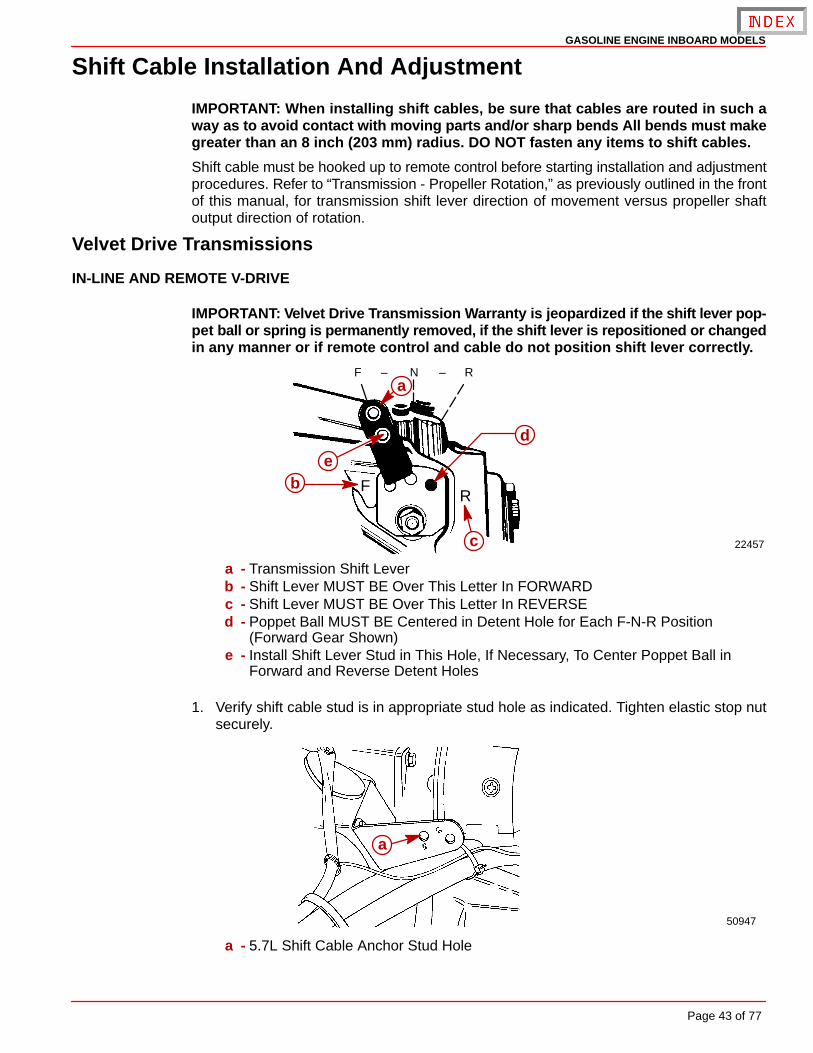
Shift Cable Installation And Adjustment
IMPORTANT: When installing shift cables, be sure that cables are routed in such away as to avoid contact with moving parts and/or sharp bends All bends must makegreater than an 8 inch (203 mm) radius. DO NOT fasten any items to shift cables.
Shift cable must be hooked up to remote control before starting installation and adjustmentprocedures. Refer to “Transmission - Propeller Rotation,” as previously outlined in the frontof this manual, for transmission shift lever direction of movement versus propeller shaftoutput direction of rotation.
Velvet Drive Transmissions
IN-LINE AND REMOTE V-DRIVE
IMPORTANT: Velvet Drive Transmission Warranty is jeopardized if the shift lever pop-pet ball or spring is permanently removed, if the shift lever is repositioned or changedin any manner or if remote control and cable do not position shift lever correctly.
22457
F N R– –
FR
a
b
c
d
e
a - Transmission Shift Leverb - Shift Lever MUST BE Over This Letter In FORWARDc - Shift Lever MUST BE Over This Letter In REVERSEd - Poppet Ball MUST BE Centered in Detent Hole for Each F-N-R Position
(Forward Gear Shown)e - Install Shift Lever Stud in This Hole, If Necessary, To Center Poppet Ball in
Forward and Reverse Detent Holes
1. Verify shift cable stud is in appropriate stud hole as indicated. Tighten elastic stop nutsecurely.
50947
a
a - 5.7L Shift Cable Anchor Stud Hole

GASOLINE ENGINE INBOARD MODELS
Page 44 of 77
2. Place remote control shift lever and transmission shift lever in neutral position.
3. Remove nuts and washers from shift cable attaching studs.
4. Locate center of remote control and control shift cable play (backlash), as follows:
a. Ensure that remote control is in neutral position.
b. Push in on control cable end with enough pressure to remove play and mark position“a” on tube.
c. Pull out on control cable end with enough pressure to remove play and mark position“b” on tube.
d. Measure distance between marks “a” and “b,” and mark position “c,” half-waybetween marks “a” and “b.”
22024
a
b c
c
5. Center cable-end play, then adjust cable barrel to align holes in barrel and in cable endguide, with attaching points on transmission.
6. Temporarily install shift cable. Do not secure at this time.
7. Place remote control shift lever in forward gear position and check position of transmis-sion shift lever. Shift lever must be positioned as previously indicated.
8. Place remote control lever in reverse gear position and again check shift lever position.Lever must be positioned as previously indicated.
GASOLINE ENGINE INBOARD MODELS
Page 45 of 77
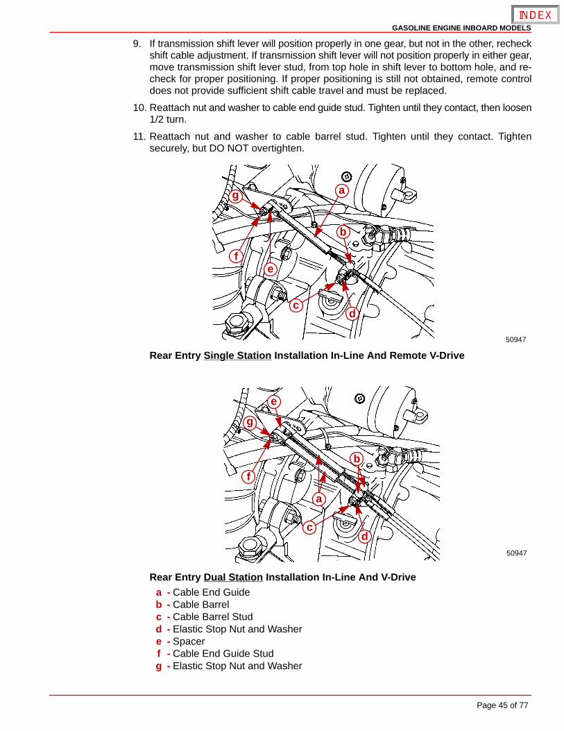
9. If transmission shift lever will position properly in one gear, but not in the other, recheckshift cable adjustment. If transmission shift lever will not position properly in either gear,move transmission shift lever stud, from top hole in shift lever to bottom hole, and re-check for proper positioning. If proper positioning is still not obtained, remote controldoes not provide sufficient shift cable travel and must be replaced.
10. Reattach nut and washer to cable end guide stud. Tighten until they contact, then loosen1/2 turn.
11. Reattach nut and washer to cable barrel stud. Tighten until they contact. Tightensecurely, but DO NOT overtighten.
50947
a
b
cd
ef
g
Rear Entry Single Station Installation In-Line And Remote V-Drive
50947
a
b
cd
e
f
g
Rear Entry Dual Station Installation In-Line And V-Drivea - Cable End Guideb - Cable Barrelc - Cable Barrel Studd - Elastic Stop Nut and Washere - Spacerf - Cable End Guide Studg - Elastic Stop Nut and Washer
GASOLINE ENGINE INBOARD MODELS
Page 46 of 77
50946
a
b
c
d
ef
g
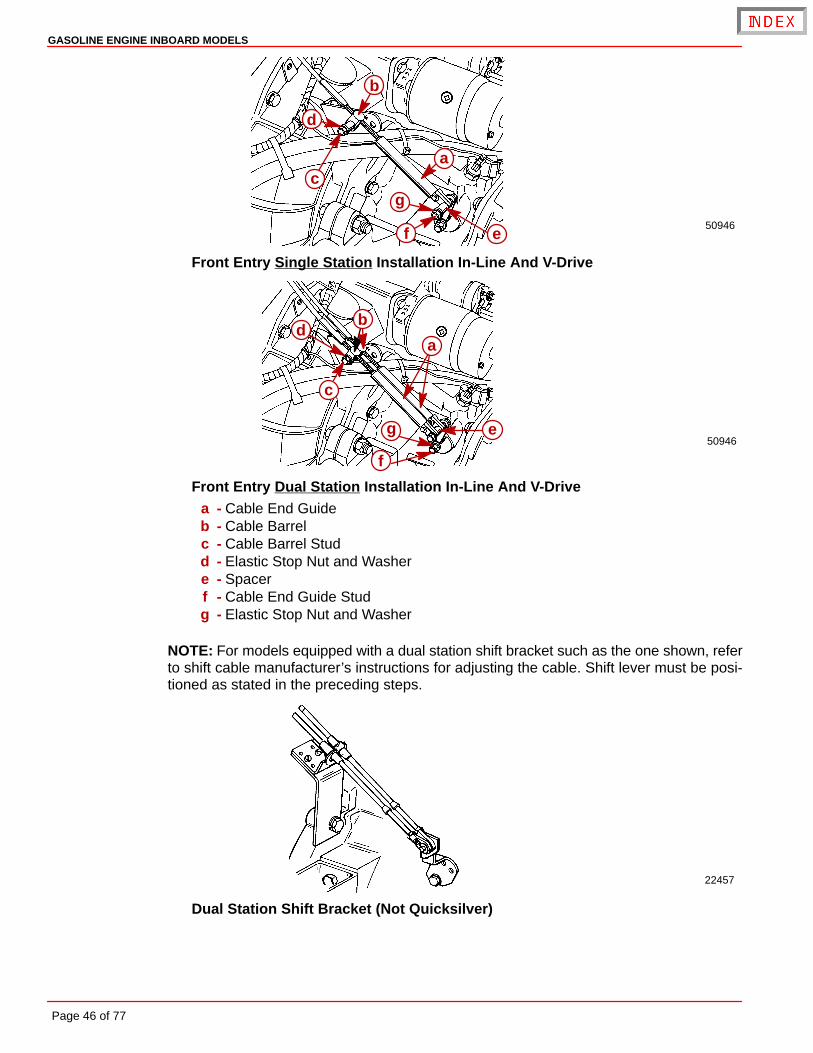
Front Entry Single Station Installation In-Line And V-Drive
50946
a
b
c
d
e
f
g
Front Entry Dual Station Installation In-Line And V-Drivea - Cable End Guideb - Cable Barrelc - Cable Barrel Studd - Elastic Stop Nut and Washere - Spacerf - Cable End Guide Studg - Elastic Stop Nut and Washer
NOTE: For models equipped with a dual station shift bracket such as the one shown, referto shift cable manufacturer’s instructions for adjusting the cable. Shift lever must be posi-tioned as stated in the preceding steps.
22457
Dual Station Shift Bracket (Not Quicksilver)
GASOLINE ENGINE INBOARD MODELS
Page 47 of 77
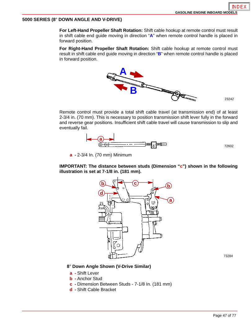
5000 SERIES (8° DOWN ANGLE AND V-DRIVE)
For Left-Hand Propeller Shaft Rotation: Shift cable hookup at remote control must resultin shift cable end guide moving in direction “A” when remote control handle is placed inforward position.
For Right-Hand Propeller Shaft Rotation: Shift cable hookup at remote control mustresult in shift cable end guide moving in direction “B” when remote control handle is placedin forward position.
23242
A
B
Remote control must provide a total shift cable travel (at transmission end) of at least2-3/4 in. (70 mm). This is necessary to position transmission shift lever fully in the forwardand reverse gear positions. Insufficient shift cable travel will cause transmission to slip andeventually fail.
72602
a
a - 2-3/4 In. (70 mm) Minimum
IMPORTANT: The distance between studs (Dimension “c”) shown in the followingillustration is set at 7-1/8 in. (181 mm).
73284
b c
db
a
8° Down Angle Shown (V-Drive Similar)a - Shift Leverb - Anchor Studc - Dimension Between Studs - 7-1/8 In. (181 mm)d - Shift Cable Bracket
GASOLINE ENGINE INBOARD MODELS
Page 48 of 77
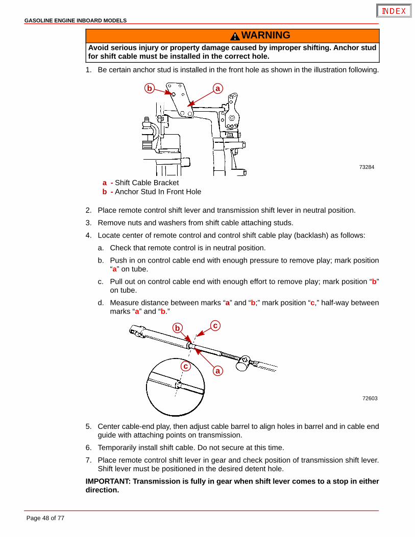
WARNINGAvoid serious injury or property damage caused by improper shifting. Anchor studfor shift cable must be installed in the correct hole.
1. Be certain anchor stud is installed in the front hole as shown in the illustration following.
73284
ab
a - Shift Cable Bracketb - Anchor Stud In Front Hole
2. Place remote control shift lever and transmission shift lever in neutral position.
3. Remove nuts and washers from shift cable attaching studs.
4. Locate center of remote control and control shift cable play (backlash) as follows:
a. Check that remote control is in neutral position.
b. Push in on control cable end with enough pressure to remove play; mark position“a” on tube.
c. Pull out on control cable end with enough effort to remove play; mark position “b”on tube.
d. Measure distance between marks “a” and “b;” mark position “c,” half-way betweenmarks “a” and “b.”
72603
cb
c a
5. Center cable-end play, then adjust cable barrel to align holes in barrel and in cable endguide with attaching points on transmission.
6. Temporarily install shift cable. Do not secure at this time.
7. Place remote control shift lever in gear and check position of transmission shift lever.Shift lever must be positioned in the desired detent hole.
IMPORTANT: Transmission is fully in gear when shift lever comes to a stop in eitherdirection.
GASOLINE ENGINE INBOARD MODELS
Page 49 of 77
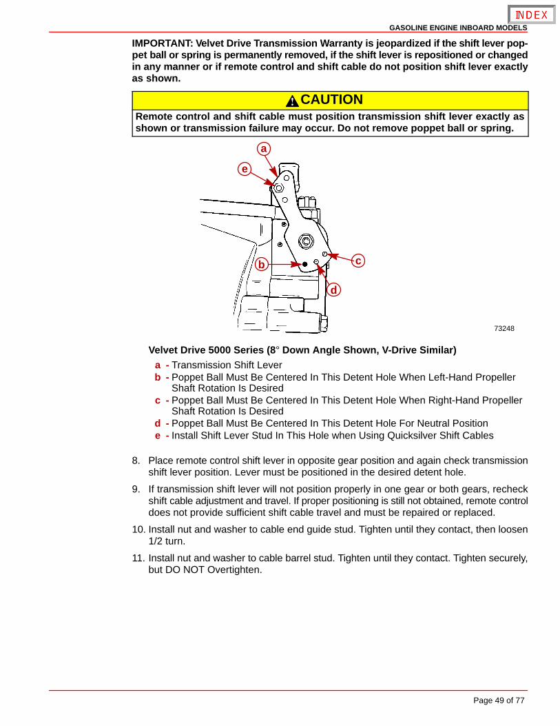
IMPORTANT: Velvet Drive Transmission Warranty is jeopardized if the shift lever pop-pet ball or spring is permanently removed, if the shift lever is repositioned or changedin any manner or if remote control and shift cable do not position shift lever exactlyas shown.
CAUTIONRemote control and shift cable must position transmission shift lever exactly asshown or transmission failure may occur. Do not remove poppet ball or spring.
73248
e
b c
a
d
Velvet Drive 5000 Series (8° Down Angle Shown, V-Drive Similar)a - Transmission Shift Leverb - Poppet Ball Must Be Centered In This Detent Hole When Left-Hand Propeller
Shaft Rotation Is Desiredc - Poppet Ball Must Be Centered In This Detent Hole When Right-Hand Propeller
Shaft Rotation Is Desiredd - Poppet Ball Must Be Centered In This Detent Hole For Neutral Positione - Install Shift Lever Stud In This Hole when Using Quicksilver Shift Cables
8. Place remote control shift lever in opposite gear position and again check transmissionshift lever position. Lever must be positioned in the desired detent hole.
9. If transmission shift lever will not position properly in one gear or both gears, recheckshift cable adjustment and travel. If proper positioning is still not obtained, remote controldoes not provide sufficient shift cable travel and must be repaired or replaced.
10. Install nut and washer to cable end guide stud. Tighten until they contact, then loosen1/2 turn.
11. Install nut and washer to cable barrel stud. Tighten until they contact. Tighten securely,but DO NOT Overtighten.
GASOLINE ENGINE INBOARD MODELS
Page 50 of 77
71780 71972
ab
c
e
e
f
c
db
g
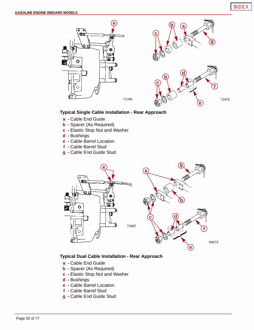
Typical Single Cable Installation - Rear Approacha - Cable End Guideb - Spacer (As Required)c - Elastic Stop Nut and Washerd - Bushingse - Cable Barrel Locationf - Cable Barrel Studg - Cable End Guide Stud
71897
50073
g
b
ea
dc
f
e
Typical Dual Cable Installation - Rear Approacha - Cable End Guideb - Spacer (As Required)c - Elastic Stop Nut and Washerd - Bushingse - Cable Barrel Locationf - Cable Barrel Studg - Cable End Guide Stud
GASOLINE ENGINE INBOARD MODELS
Page 51 of 77
Hurth Transmissions
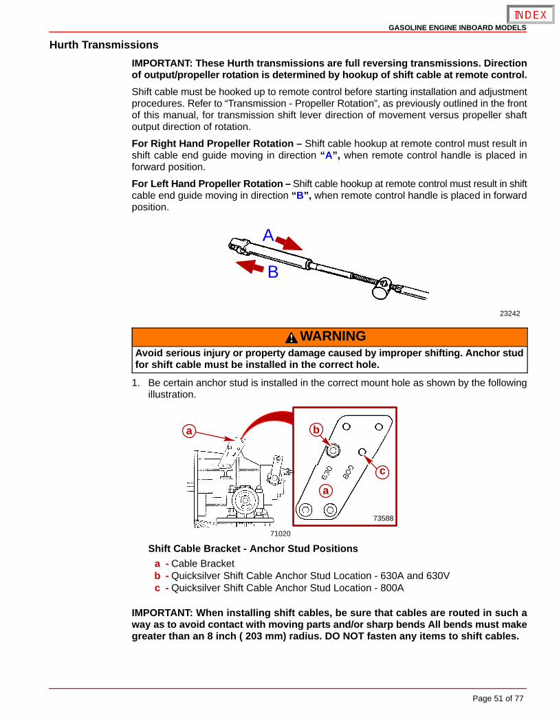
IMPORTANT: These Hurth transmissions are full reversing transmissions. Directionof output/propeller rotation is determined by hookup of shift cable at remote control.
Shift cable must be hooked up to remote control before starting installation and adjustmentprocedures. Refer to “Transmission - Propeller Rotation”, as previously outlined in the frontof this manual, for transmission shift lever direction of movement versus propeller shaftoutput direction of rotation.
For Right Hand Propeller Rotation – Shift cable hookup at remote control must result inshift cable end guide moving in direction “A”, when remote control handle is placed inforward position.
For Left Hand Propeller Rotation – Shift cable hookup at remote control must result in shiftcable end guide moving in direction “B”, when remote control handle is placed in forwardposition.
23242
A
B
WARNINGAvoid serious injury or property damage caused by improper shifting. Anchor studfor shift cable must be installed in the correct hole.
1. Be certain anchor stud is installed in the correct mount hole as shown by the followingillustration.
73588
71020
a
c
ba
Shift Cable Bracket - Anchor Stud Positionsa - Cable Bracketb - Quicksilver Shift Cable Anchor Stud Location - 630A and 630Vc - Quicksilver Shift Cable Anchor Stud Location - 800A
IMPORTANT: When installing shift cables, be sure that cables are routed in such away as to avoid contact with moving parts and/or sharp bends All bends must makegreater than an 8 inch ( 203 mm) radius. DO NOT fasten any items to shift cables.
GASOLINE ENGINE INBOARD MODELS
Page 52 of 77
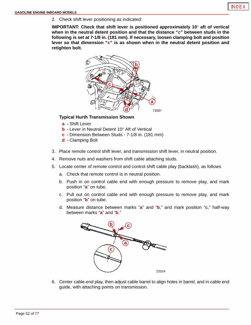
2. Check shift lever positioning as indicated:
IMPORTANT: Check that shift lever is positioned approximately 10° aft of verticalwhen in the neutral detent position and that the distance “c” between studs in thefollowing is set at 7-1/8 in. (181 mm). If necessary, loosen clamping bolt and positionlever so that dimension “c” is as shown when in the neutral detent position andretighten bolt.
73587
a
b
d
c
Typical Hurth Transmission Showna - Shift Leverb - Lever in Neutral Detent 10° Aft of Verticalc - Dimension Between Studs - 7-1/8 in. (181 mm)d - Clamping Bolt
3. Place remote control shift lever, and transmission shift lever, in neutral position.
4. Remove nuts and washers from shift cable attaching studs.
5. Locate center of remote control and control shift cable play (backlash), as follows:
a. Check that remote control is in neutral position.
b. Push in on control cable end with enough pressure to remove play, and markposition “a” on tube.
c. Pull out on control cable end with enough pressure to remove play, and markposition “b” on tube.
d. Measure distance between marks “a” and “b,” and mark position “c,” half-waybetween marks “a” and “b.”
22024
a
b c
c
6. Center cable-end play, then adjust cable barrel to align holes in barrel, and in cable endguide, with attaching points on transmission.
GASOLINE ENGINE INBOARD MODELS
Page 53 of 77
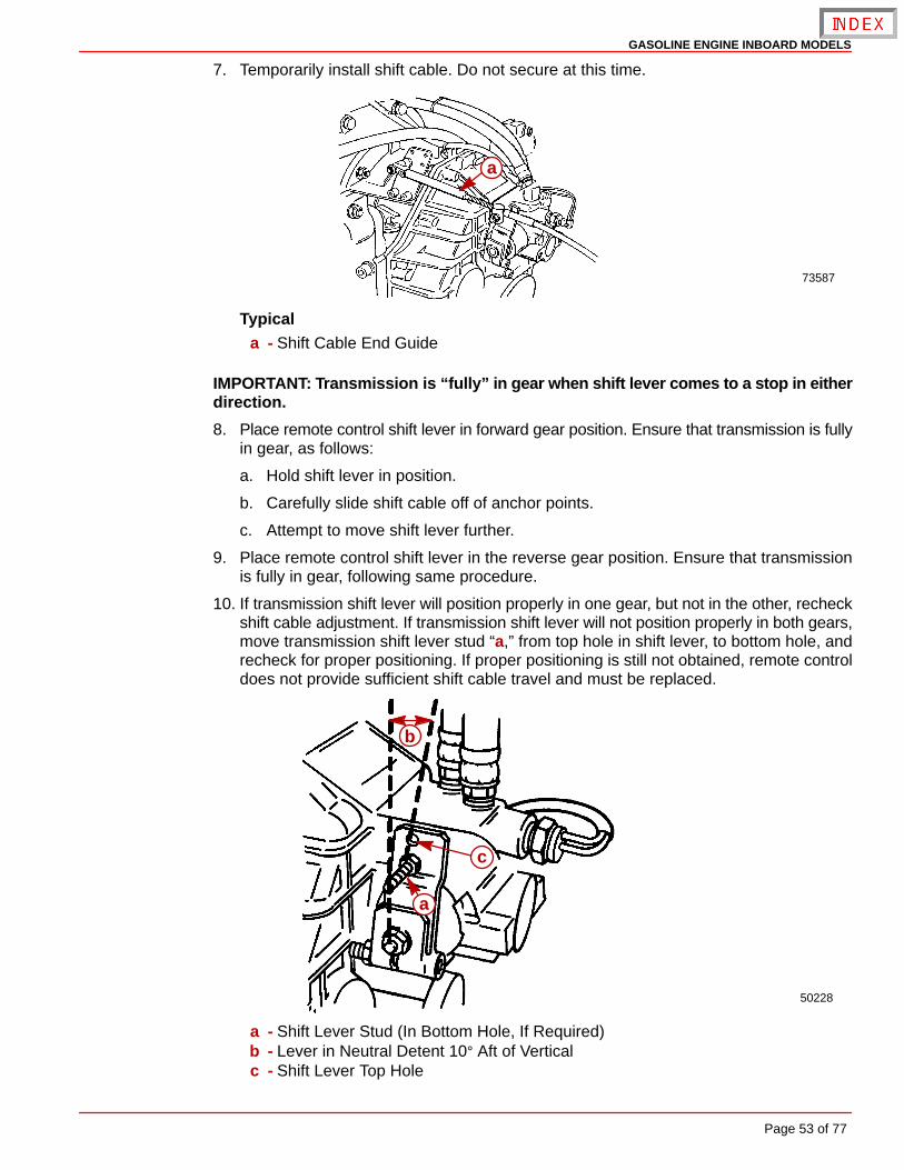
7. Temporarily install shift cable. Do not secure at this time.
73587
a
Typicala - Shift Cable End Guide
IMPORTANT: Transmission is “fully” in gear when shift lever comes to a stop in eitherdirection.
8. Place remote control shift lever in forward gear position. Ensure that transmission is fullyin gear, as follows:
a. Hold shift lever in position.
b. Carefully slide shift cable off of anchor points.
c. Attempt to move shift lever further.
9. Place remote control shift lever in the reverse gear position. Ensure that transmissionis fully in gear, following same procedure.
10. If transmission shift lever will position properly in one gear, but not in the other, recheckshift cable adjustment. If transmission shift lever will not position properly in both gears,move transmission shift lever stud “a,” from top hole in shift lever, to bottom hole, andrecheck for proper positioning. If proper positioning is still not obtained, remote controldoes not provide sufficient shift cable travel and must be replaced.
50228
a
b
c
a - Shift Lever Stud (In Bottom Hole, If Required)b - Lever in Neutral Detent 10° Aft of Verticalc - Shift Lever Top Hole
GASOLINE ENGINE INBOARD MODELS
Page 54 of 77
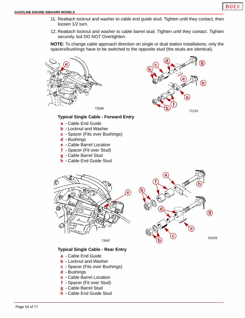
11. Reattach locknut and washer to cable end guide stud. Tighten until they contact, thenloosen 1/2 turn.
12. Reattach locknut and washer to cable barrel stud. Tighten until they contact. Tightensecurely, but DO NOT Overtighten.
NOTE: To change cable approach direction on single or dual station installations, only thespacers/bushings have to be switched to the opposite stud (the studs are identical).
7358971210
a
b
cd
f
e
bg
h
e
Typical Single Cable - Forward Entrya - Cable End Guideb - Locknut and Washerc - Spacer (Fits over Bushings)d - Bushingse - Cable Barrel Locationf - Spacer (Fit over Stud)g - Cable Barrel Studh - Cable End Guide Stud
7358750229
e
e
fa
b
bc
dg
h
Typical Single Cable - Rear Entrya - Cable End Guideb - Locknut and Washerc - Spacer (Fits over Bushings)d - Bushingse - Cable Barrel Locationf - Spacer (Fit over Stud)g - Cable Barrel Studh - Cable End Guide Stud
GASOLINE ENGINE INBOARD MODELS
Page 55 of 77
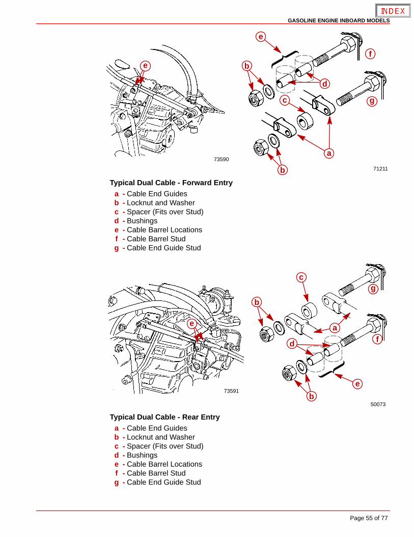
73590
71211
e
e
b
b
a
c
d
g
f
Typical Dual Cable - Forward Entrya - Cable End Guidesb - Locknut and Washerc - Spacer (Fits over Stud)d - Bushingse - Cable Barrel Locationsf - Cable Barrel Studg - Cable End Guide Stud
73591
50073
a
b
c
d
e
e
b
f
g
Typical Dual Cable - Rear Entrya - Cable End Guidesb - Locknut and Washerc - Spacer (Fits over Stud)d - Bushingse - Cable Barrel Locationsf - Cable Barrel Studg - Cable End Guide Stud
GASOLINE ENGINE INBOARD MODELS
Page 56 of 77
Predelivery Preparation
NOTICE
Before starting Predelivery read “General Information” and “Installation Require-ments” completely.
Battery ConnectionIMPORTANT: Engine electrical system is negative (–) ground.
1. Connect engine positive (+) battery cable (usually red) to positive (+) battery terminal.
2. Connect engine negative (–) battery cable (usually black) to negative (–) battery termi-nal.
3. Make sure that all battery terminal connections are tight and then coat connections andterminals with a battery terminal anti-corrosion spray to help retard corrosion.
Test Running Engine
WARNINGIf engine is to be tested on land, propeller must be removed.
IMPORTANT: If engine is to be tested on land, water must be supplied to seawaterpickup pump. DO NOT run engine above 1500 rpm.
GASOLINE ENGINE INBOARD MODELS
Page 57 of 77
Boat-In-The-Water TestsIMPORTANT: Engine alignment MUST BE CHECKED with boat in the water, fuel tanksfilled, and with a normal load on board.
ENGINE IDLE SPEED ADJUSTMENT (CARBURETED MODELS)
CAUTIONAvoid engine damage. Ensure that cooling water is supplied to the engine if it willbe run with boat out of the water. See instructions in the Operation, Maintenanceand Warranty Manual entitled “Flushing Cooling System” for instructions on con-necting flush device.
The engine should idle at rpm (as specified in “Operation, Maintenance and WarrantyManual”) with engine at normal operating temperature. If idle speed is incorrect, proceedas follows:
IMPORTANT: In order to properly set idle speed, the ignition module MUST BE lockedin the “Base Timing Mode.” This is necessary because of the “Idle Speed Control”feature that exists in the ignition module. This must be done before the key switchis turned to the ON or START position.
1. Connect a shop tachometer to engine.
2. Using a jumper wire, connect the ignition system Timing Lead (PUR/WHT wire) to agood engine ground (–). This locks the ignition module into the Base Timing Mode. Referto “Engine Wiring Harness” diagram in this manual.
3. Start engine and place the remote control lever in NEUTRAL, idle position.
4. Adjust idle speed to 650 rpm.
5. Stop engine. Readjust cable barrel and reinstall the throttle cable.
IMPORTANT: Be sure to disconnect the jumper wire from the ignition system test leadbefore attempting to resume normal operations. If the jumper wire is left in place, theignition module will operate in the Base Timing Mode. This means that the additionaltiming advance features would not be functioning.
6. Remove the jumper wire from the timing lead.
ENGINE IDLE SPEED ADJUSTMENT (EFI MODELS)
CAUTIONAvoid engine damage. Ensure that cooling water is supplied to the engine if it willbe run with boat out of the water. See instructions in the Operation, Maintenanceand Warranty Manual entitled “Flushing Cooling System,” for instructions on con-necting flush device.
Engine should idle at rpm (as specified in “Operation, Maintenance and Warranty Manual”)with engine at normal operating temperature. If idle speed is incorrect, proceed as follows:
1. Ensure that throttle cable has been adjusted properly.
2. If idle speed is still not correct, it may be necessary to perform EFI System DiagnosticTests on the idle circuit. Refer to the appropriate Mercury MerCruiser Service Manualfor procedures.
GASOLINE ENGINE INBOARD MODELS
Page 58 of 77
WIDE-OPEN-THROTTLE TEST
IMPORTANT: To run engine at full throttle before the break-in period is complete, fol-low this procedure.
1. Start engine and run at idle rpm until normal operating temperature is reached.
2. Run boat up on plane.
3. Advance engine rpm (in 200 rpm increments) until engine reaches its maximum ratedrpm.
To test if the correct propeller has been installed, operate boat (with normal load on board)at WOT and check rpm with an accurate tachometer. Engine rpm should be near top of thespecified range so that, under a heavy load, engine speed will not fall below specifications.If engine speed is too high, replace propeller with a higher pitch propeller. Normally a 1 inchpropeller pitch change causes an rpm change of 150 rpm.
Cold Weather and Extended Storage Draining Instructions
CAUTIONIf boat is to remain in water after draining, seawater inlet hose must be removed andplugged to prevent a siphoning action that may occur, allowing seawater to flowfrom the drain holes or removed hoses.
CAUTIONSeawater section of cooling system MUST BE COMPLETELY drained for winterstorage, or immediately after cold weather use, if the possibility of freezing temper-atures exist. Failure to comply may result in trapped water causing freeze and/orcorrosion damage to engine.
IMPORTANT: Boat must be as level as possible to ensure complete draining of cool-ing system.
IMPORTANT: Mercury MerCruiser recommends that propylene glycol (a nontoxicand environmentally safe) antifreeze be used in the seawater section of the coolingsystem for cold weather or extended storage. Make sure that the propylene glycolantifreeze contains a rust inhibitor and is recommended for use in marine engines.Be certain to follow the propylene glycol manufacturer’s recommendations.
SEAWATER (RAW WATER) COOLED MODELS
Carbureted Models
1. Ensure engine is as level as possible to ensure complete draining of cooling system.
2. Remove drain plugs from following locations:
a. Port Side - from cylinder block.
CAUTIONAvoid product damage. Do not disturb the Y-fitting when removing the drain plug.There is an ignition control Knock Sensor in the upper hole of the fitting. This sen-sor must not be loosened or removed. It is tightened to a critical specification at thefactory.
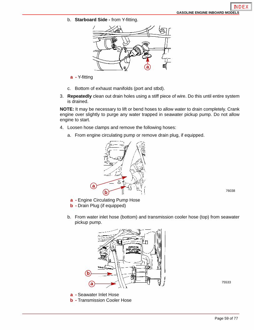
GASOLINE ENGINE INBOARD MODELS
Page 59 of 77
b. Starboard Side - from Y-fitting.
a
a - Y-fitting
c. Bottom of exhaust manifolds (port and stbd).
3. Repeatedly clean out drain holes using a stiff piece of wire. Do this until entire systemis drained.
NOTE: It may be necessary to lift or bend hoses to allow water to drain completely. Crankengine over slightly to purge any water trapped in seawater pickup pump. Do not allowengine to start.
4. Loosen hose clamps and remove the following hoses:
a. From engine circulating pump or remove drain plug, if equipped.
76038a
b
a - Engine Circulating Pump Hoseb - Drain Plug (if equipped)
b. From water inlet hose (bottom) and transmission cooler hose (top) from seawaterpickup pump.
75533a
b
a - Seawater Inlet Hoseb - Transmission Cooler Hose
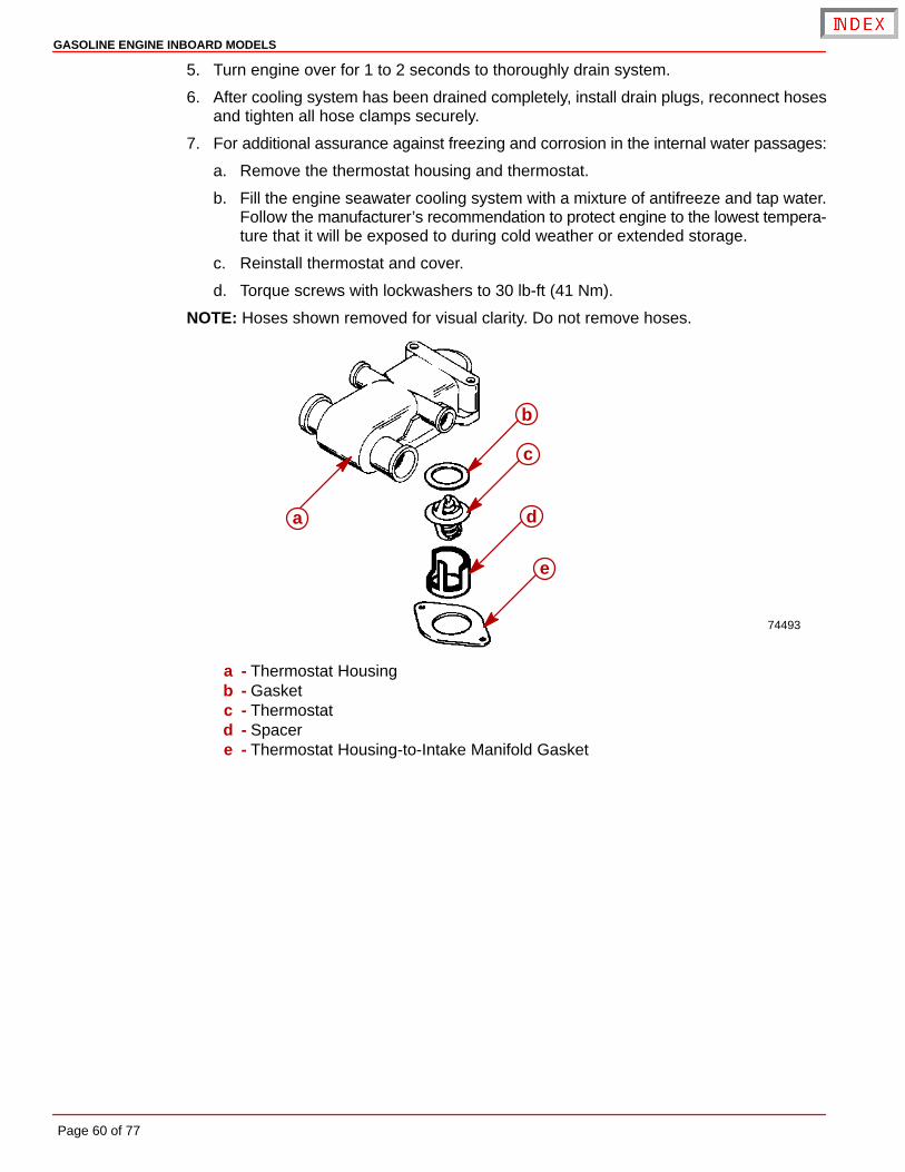
GASOLINE ENGINE INBOARD MODELS
Page 60 of 77
5. Turn engine over for 1 to 2 seconds to thoroughly drain system.
6. After cooling system has been drained completely, install drain plugs, reconnect hosesand tighten all hose clamps securely.
7. For additional assurance against freezing and corrosion in the internal water passages:
a. Remove the thermostat housing and thermostat.
b. Fill the engine seawater cooling system with a mixture of antifreeze and tap water.Follow the manufacturer’s recommendation to protect engine to the lowest tempera-ture that it will be exposed to during cold weather or extended storage.
c. Reinstall thermostat and cover.
d. Torque screws with lockwashers to 30 lb-ft (41 Nm).
NOTE: Hoses shown removed for visual clarity. Do not remove hoses.
74493
a
b
c
d
e
a - Thermostat Housingb - Gasketc - Thermostatd - Spacere - Thermostat Housing-to-Intake Manifold Gasket
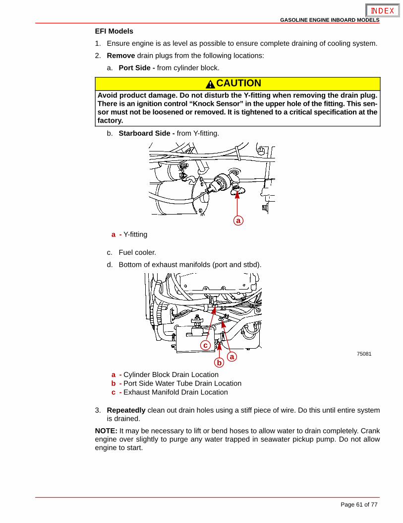
GASOLINE ENGINE INBOARD MODELS
Page 61 of 77
EFI Models
1. Ensure engine is as level as possible to ensure complete draining of cooling system.
2. Remove drain plugs from the following locations:
a. Port Side - from cylinder block.
CAUTIONAvoid product damage. Do not disturb the Y-fitting when removing the drain plug.There is an ignition control “Knock Sensor” in the upper hole of the fitting. This sen-sor must not be loosened or removed. It is tightened to a critical specification at thefactory.
b. Starboard Side - from Y-fitting.
a
a - Y-fitting
c. Fuel cooler.
d. Bottom of exhaust manifolds (port and stbd).
75081ab
c
a - Cylinder Block Drain Locationb - Port Side Water Tube Drain Locationc - Exhaust Manifold Drain Location
3. Repeatedly clean out drain holes using a stiff piece of wire. Do this until entire systemis drained.
NOTE: It may be necessary to lift or bend hoses to allow water to drain completely. Crankengine over slightly to purge any water trapped in seawater pickup pump. Do not allowengine to start.
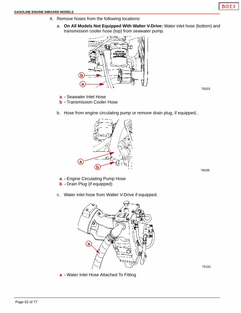
GASOLINE ENGINE INBOARD MODELS
Page 62 of 77
4. Remove hoses from the following locations:
a. On All Models Not Equipped With Walter V-Drive: Water inlet hose (bottom) andtransmission cooler hose (top) from seawater pump.
75533a
b
a - Seawater Inlet Hoseb - Transmission Cooler Hose
b. Hose from engine circulating pump or remove drain plug, if equipped..
76038
ab
a - Engine Circulating Pump Hoseb - Drain Plug (if equipped)
c. Water inlet hose from Walter V-Drive if equipped.
75191
a
a - Water Inlet Hose Attached To Fitting
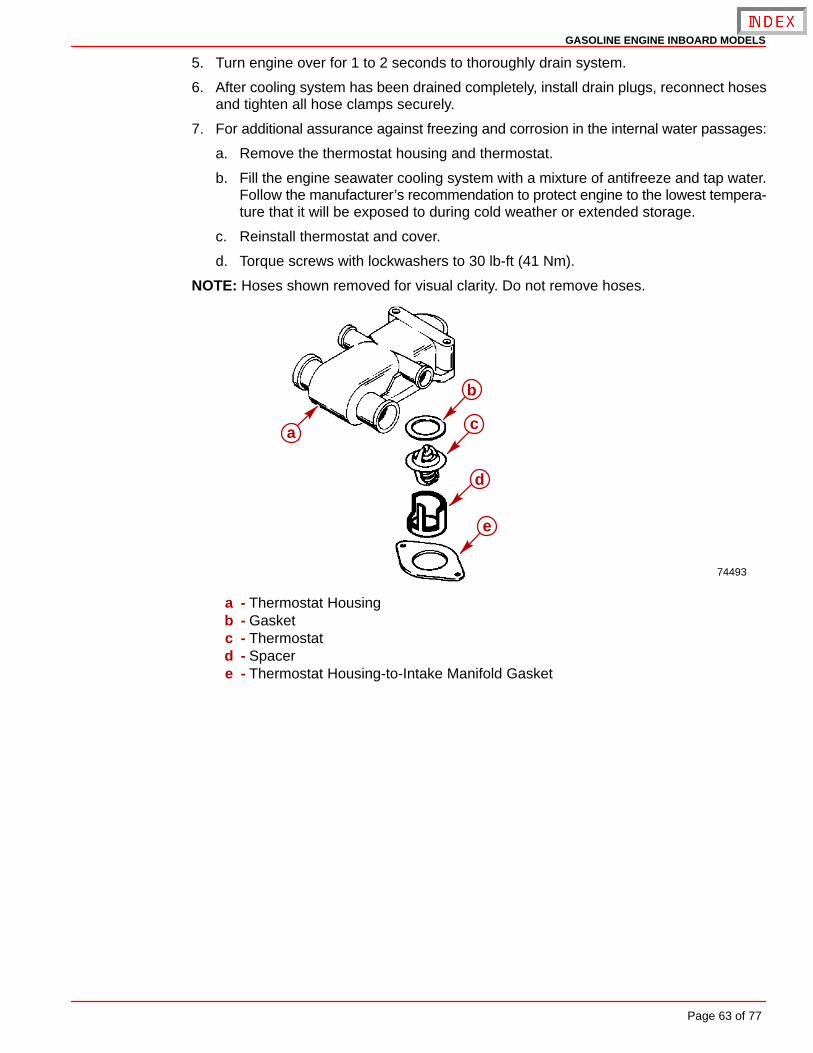
GASOLINE ENGINE INBOARD MODELS
Page 63 of 77
5. Turn engine over for 1 to 2 seconds to thoroughly drain system.
6. After cooling system has been drained completely, install drain plugs, reconnect hosesand tighten all hose clamps securely.
7. For additional assurance against freezing and corrosion in the internal water passages:
a. Remove the thermostat housing and thermostat.
b. Fill the engine seawater cooling system with a mixture of antifreeze and tap water.Follow the manufacturer’s recommendation to protect engine to the lowest tempera-ture that it will be exposed to during cold weather or extended storage.
c. Reinstall thermostat and cover.
d. Torque screws with lockwashers to 30 lb-ft (41 Nm).
NOTE: Hoses shown removed for visual clarity. Do not remove hoses.
74493
a
b
c
d
e
a - Thermostat Housingb - Gasketc - Thermostatd - Spacere - Thermostat Housing-to-Intake Manifold Gasket
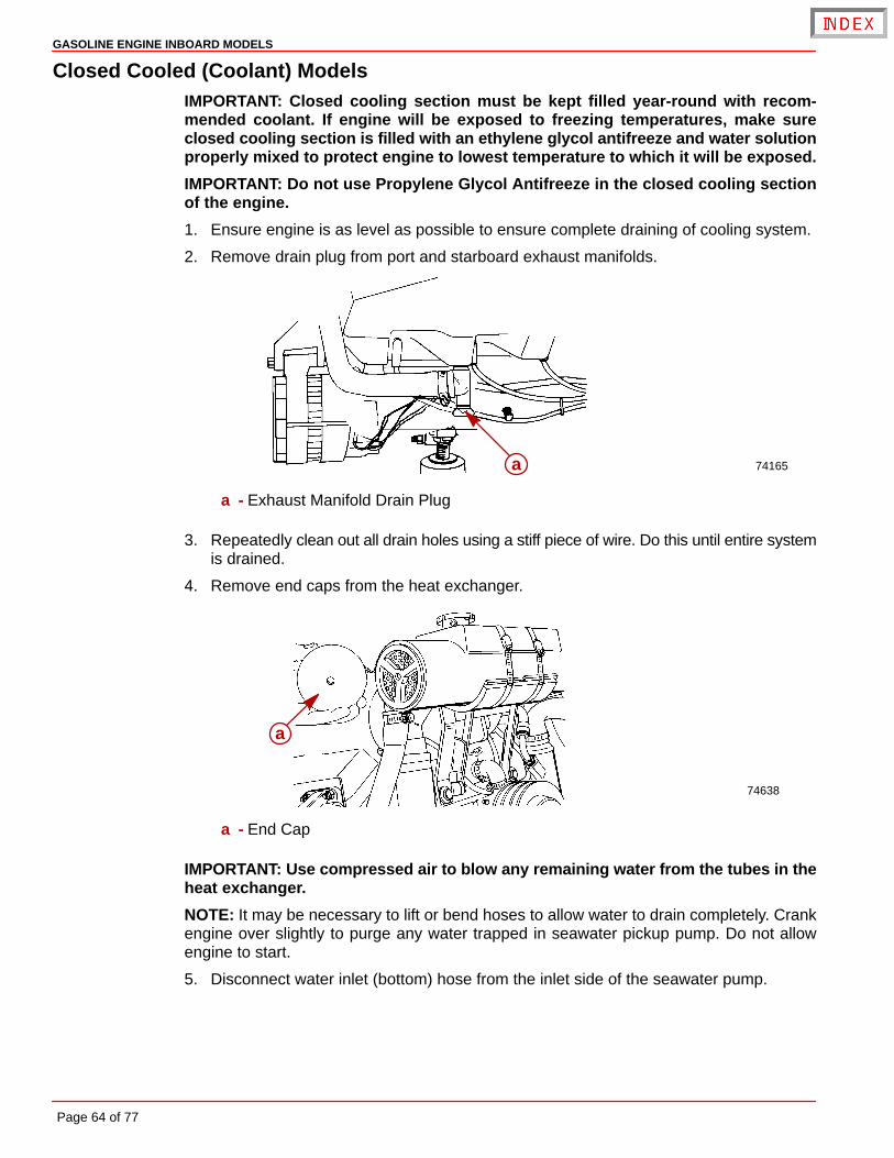
GASOLINE ENGINE INBOARD MODELS
Page 64 of 77
Closed Cooled (Coolant) ModelsIMPORTANT: Closed cooling section must be kept filled year-round with recom-mended coolant. If engine will be exposed to freezing temperatures, make sureclosed cooling section is filled with an ethylene glycol antifreeze and water solutionproperly mixed to protect engine to lowest temperature to which it will be exposed.
IMPORTANT: Do not use Propylene Glycol Antifreeze in the closed cooling sectionof the engine.
1. Ensure engine is as level as possible to ensure complete draining of cooling system.
2. Remove drain plug from port and starboard exhaust manifolds.
74165a
a - Exhaust Manifold Drain Plug
3. Repeatedly clean out all drain holes using a stiff piece of wire. Do this until entire systemis drained.
4. Remove end caps from the heat exchanger.
74638
a
a - End Cap
IMPORTANT: Use compressed air to blow any remaining water from the tubes in theheat exchanger.
NOTE: It may be necessary to lift or bend hoses to allow water to drain completely. Crankengine over slightly to purge any water trapped in seawater pickup pump. Do not allowengine to start.
5. Disconnect water inlet (bottom) hose from the inlet side of the seawater pump.
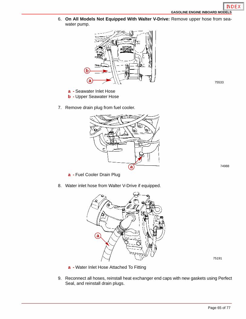
GASOLINE ENGINE INBOARD MODELS
Page 65 of 77
6. On All Models Not Equipped With Walter V-Drive: Remove upper hose from sea-water pump.
75533a
b
a - Seawater Inlet Hoseb - Upper Seawater Hose
7. Remove drain plug from fuel cooler.
74988a
a - Fuel Cooler Drain Plug
8. Water inlet hose from Walter V-Drive if equipped.
75191
a
a - Water Inlet Hose Attached To Fitting
9. Reconnect all hoses, reinstall heat exchanger end caps with new gaskets using PerfectSeal, and reinstall drain plugs.
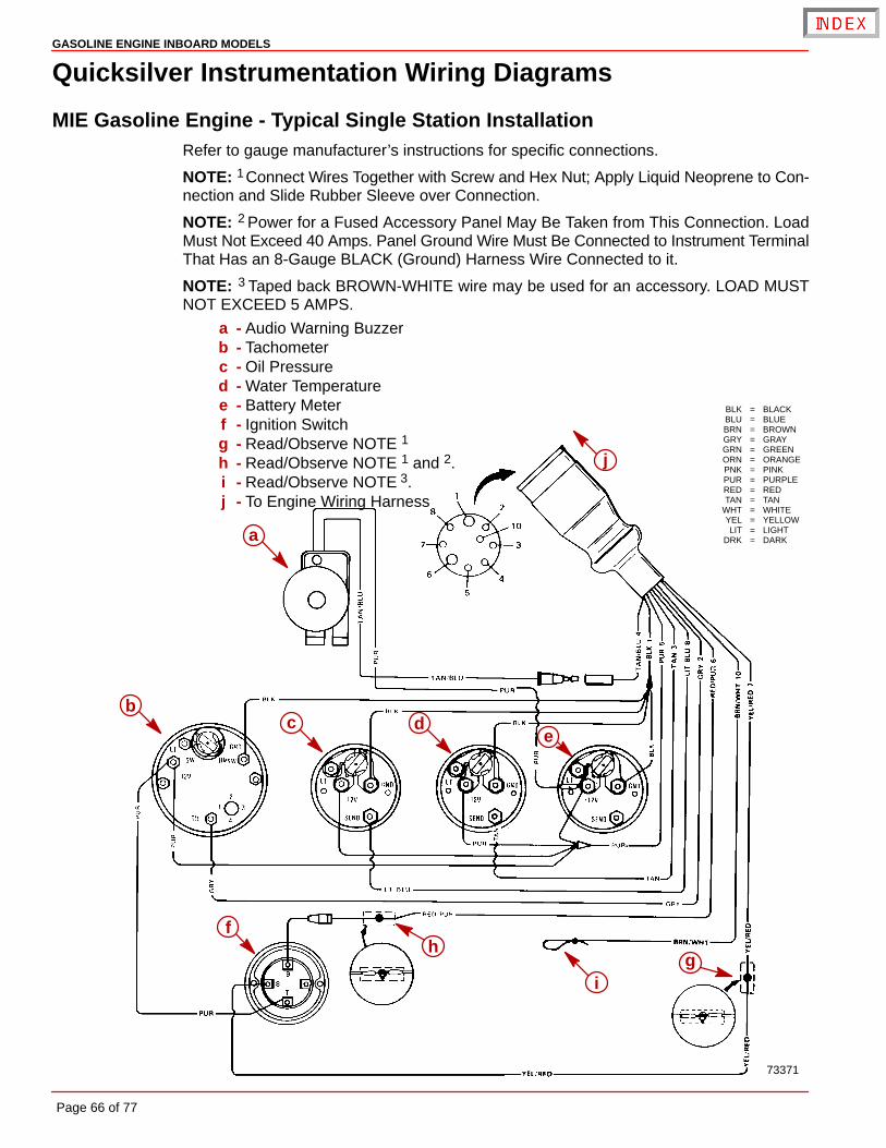
73371
BLK = BLACKBLU = BLUEBRN = BROWNGRY = GRAYGRN = GREENORN = ORANGEPNK = PINKPUR = PURPLERED = REDTAN = TAN
WHT = WHITEYEL = YELLOWLIT = LIGHT
DRK = DARKa
bc d
e
fh
ig
j
GASOLINE ENGINE INBOARD MODELS
Page 66 of 77
Quicksilver Instrumentation Wiring Diagrams
MIE Gasoline Engine - Typical Single Station InstallationRefer to gauge manufacturer’s instructions for specific connections.
NOTE: 1 Connect Wires Together with Screw and Hex Nut; Apply Liquid Neoprene to Con-nection and Slide Rubber Sleeve over Connection.
NOTE: 2 Power for a Fused Accessory Panel May Be Taken from This Connection. LoadMust Not Exceed 40 Amps. Panel Ground Wire Must Be Connected to Instrument TerminalThat Has an 8-Gauge BLACK (Ground) Harness Wire Connected to it.
NOTE: 3 Taped back BROWN-WHITE wire may be used for an accessory. LOAD MUSTNOT EXCEED 5 AMPS.
a - Audio Warning Buzzerb - Tachometerc - Oil Pressured - Water Temperaturee - Battery Meterf - Ignition Switchg - Read/Observe NOTE 1
h - Read/Observe NOTE 1 and 2.i - Read/Observe NOTE 3.j - To Engine Wiring Harness

GASOLINE ENGINE INBOARD MODELS
Page 67 of 77
THIS PAGE IS INTENTIONALLY BLANK
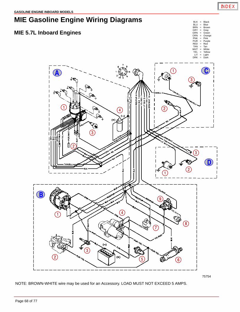
BLK = BlackBLU = BlueBRN = BrownGRY = GrayGRN = GreenORN = OrangePNK = PinkPUR = PurpleRED = RedTAN = Tan
WHT = WhiteYEL = YellowLIT = Light
DRK = Dark
NOTE: BROWN-WHITE wire may be used for an Accessory. LOAD MUST NOT EXCEED 5 AMPS.
75754
�
�
�
�
� �
�
�
�
�
�
�
�
�
�
�
�
�
� �
�
�
GASOLINE ENGINE INBOARD MODELS
Page 68 of 77
MIE Gasoline Engine Wiring Diagrams
MIE 5.7L Inboard Engines

GASOLINE ENGINE INBOARD MODELS
Page 69 of 77
A - Ignition Components1 - Distributor2 - Timing Lead3 - Knock Sensor4 - Ignition Coil
B - Starting, Charging and Choke Components1 - Alternator2 - Electric Choke3 - Ground Plug4 - Starter Motor5 - Oil Pressure Switch6 - Fuel Pump7 - Circuit Breaker8 - Neutral Safety Switch9 - Starter Slave Solenoid
C - Audio Warning Components1 - Oil Pressure Switch2 - Water Temperature Switch3 - Transmission Temperature Switch
D - Instrumentation Components1 - Oil Pressure Sender2 - Water Temperature Sender3 - See NOTE
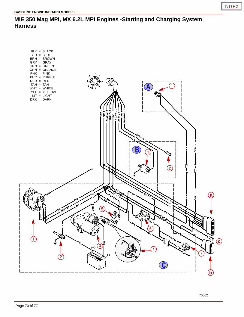
BLK = BLACKBLU = BLUEBRN = BROWNGRY = GRAYGRN = GREENORN = ORANGEPNK = PINKPUR = PURPLERED = REDTAN = TAN
WHT = WHITEYEL = YELLOWLIT = LIGHT
DRK = DARK
�
�
�
76062
�
�
�
�
c
a
b
�
�
�
�
�
�
GASOLINE ENGINE INBOARD MODELS
Page 70 of 77
MIE 350 Mag MPI, MX 6.2L MPI Engines -Starting and Charging SystemHarness
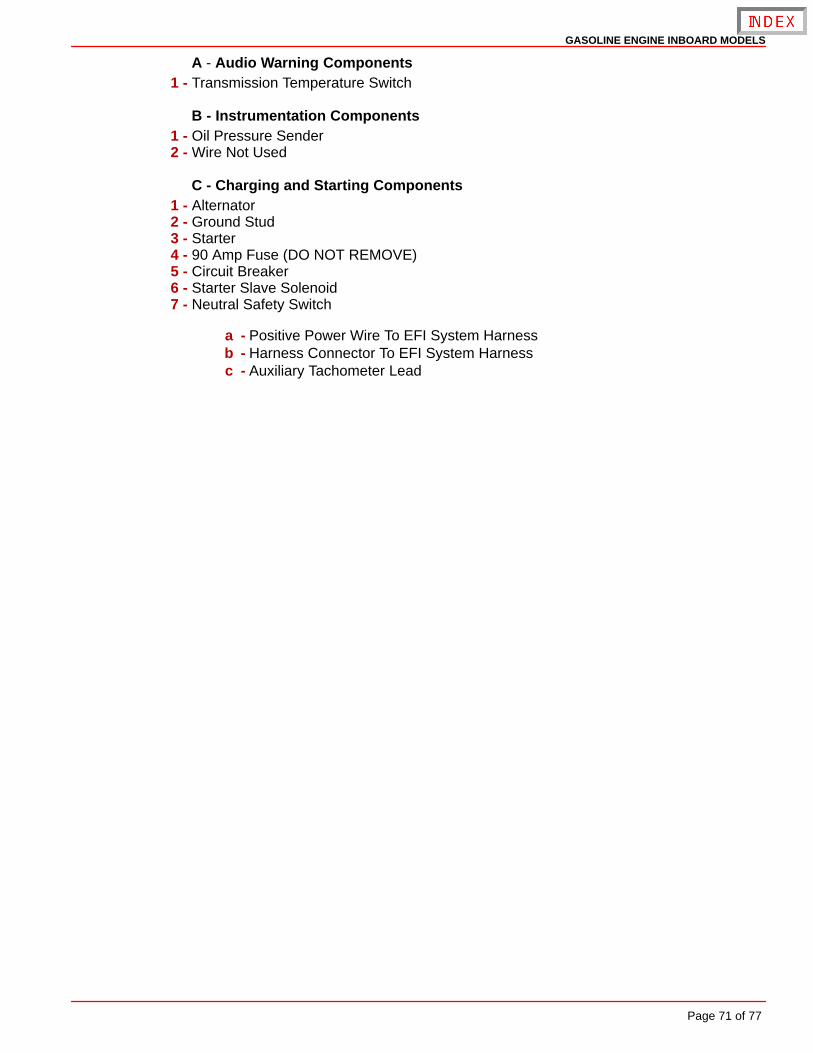
GASOLINE ENGINE INBOARD MODELS
Page 71 of 77
A - Audio Warning Components1 - Transmission Temperature Switch
B - Instrumentation Components1 - Oil Pressure Sender2 - Wire Not Used
C - Charging and Starting Components1 - Alternator2 - Ground Stud3 - Starter4 - 90 Amp Fuse (DO NOT REMOVE)5 - Circuit Breaker6 - Starter Slave Solenoid7 - Neutral Safety Switch
a - Positive Power Wire To EFI System Harnessb - Harness Connector To EFI System Harnessc - Auxiliary Tachometer Lead
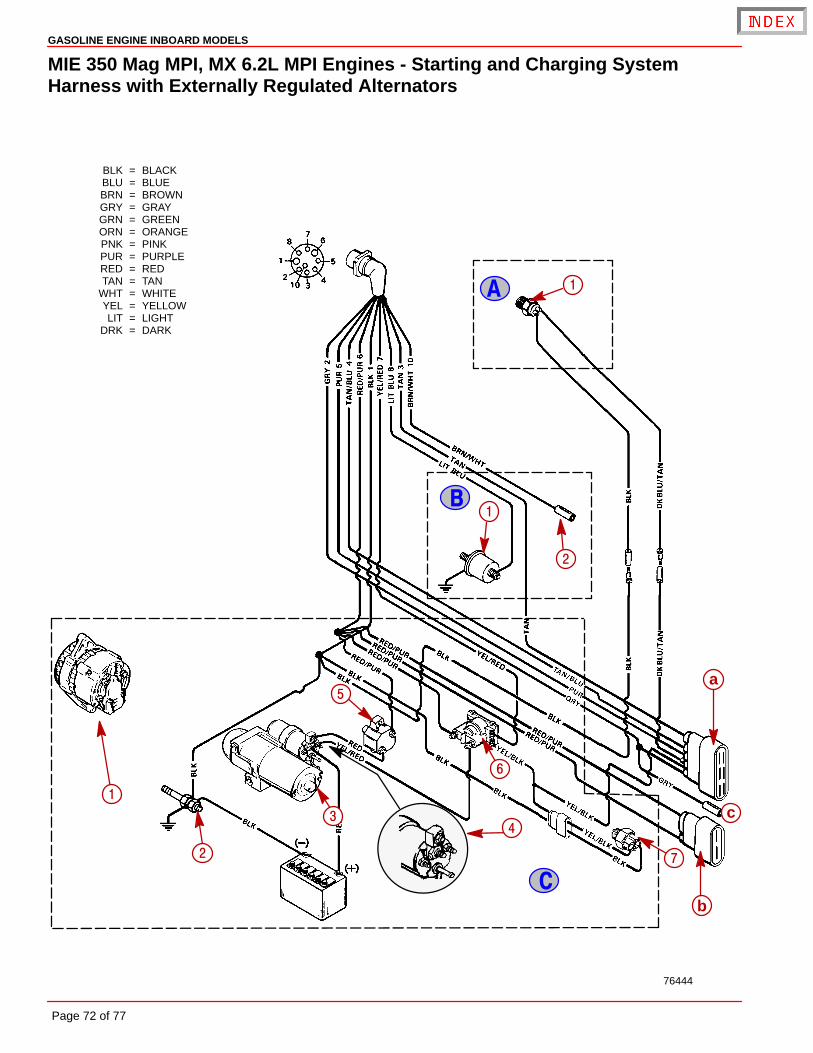
BLK = BLACKBLU = BLUEBRN = BROWNGRY = GRAYGRN = GREENORN = ORANGEPNK = PINKPUR = PURPLERED = REDTAN = TAN
WHT = WHITEYEL = YELLOWLIT = LIGHT
DRK = DARK
�
�
�
76444
�
�
�
�
c
a
b
�
�
�
�
�
�
GASOLINE ENGINE INBOARD MODELS
Page 72 of 77
MIE 350 Mag MPI, MX 6.2L MPI Engines - Starting and Charging SystemHarness with Externally Regulated Alternators
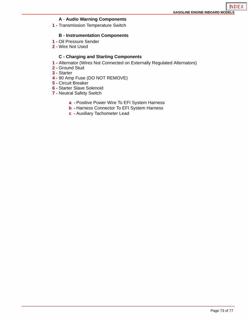
GASOLINE ENGINE INBOARD MODELS
Page 73 of 77
A - Audio Warning Components1 - Transmission Temperature Switch
B - Instrumentation Components1 - Oil Pressure Sender2 - Wire Not Used
C - Charging and Starting Components1 - Alternator (Wires Not Connected on Externally Regulated Alternators)2 - Ground Stud3 - Starter4 - 90 Amp Fuse (DO NOT REMOVE)5 - Circuit Breaker6 - Starter Slave Solenoid7 - Neutral Safety Switch
a - Positive Power Wire To EFI System Harnessb - Harness Connector To EFI System Harnessc - Auxiliary Tachometer Lead
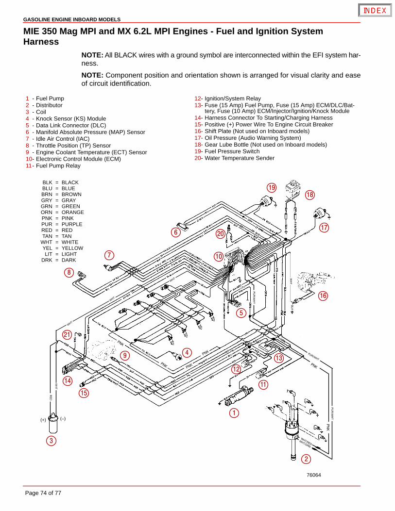
(–)(+)
76064
BLK = BLACKBLU = BLUEBRN = BROWNGRY = GRAYGRN = GREENORN = ORANGEPNK = PINKPUR = PURPLERED = REDTAN = TAN
WHT = WHITEYEL = YELLOWLIT = LIGHT
DRK = DARK
�
�
�
�
�
�
�
�
��
��
��
��
��
��
�
��
��
�
�
��
GASOLINE ENGINE INBOARD MODELS
Page 74 of 77
MIE 350 Mag MPI and MX 6.2L MPI Engines - Fuel and Ignition SystemHarness
NOTE: All BLACK wires with a ground symbol are interconnected within the EFI system har-ness.
NOTE: Component position and orientation shown is arranged for visual clarity and easeof circuit identification.
1 - Fuel Pump2 - Distributor3 - Coil4 - Knock Sensor (KS) Module5 - Data Link Connector (DLC)6 - Manifold Absolute Pressure (MAP) Sensor7 - Idle Air Control (IAC)8 - Throttle Position (TP) Sensor9 - Engine Coolant Temperature (ECT) Sensor10- Electronic Control Module (ECM)11- Fuel Pump Relay
12- Ignition/System Relay13- Fuse (15 Amp) Fuel Pump, Fuse (15 Amp) ECM/DLC/Bat-
tery, Fuse (10 Amp) ECM/Injector/Ignition/Knock Module14- Harness Connector To Starting/Charging Harness15- Positive (+) Power Wire To Engine Circuit Breaker16- Shift Plate (Not used on Inboard models)17- Oil Pressure (Audio Warning System)18- Gear Lube Bottle (Not used on Inboard models)19- Fuel Pressure Switch20- Water Temperature Sender
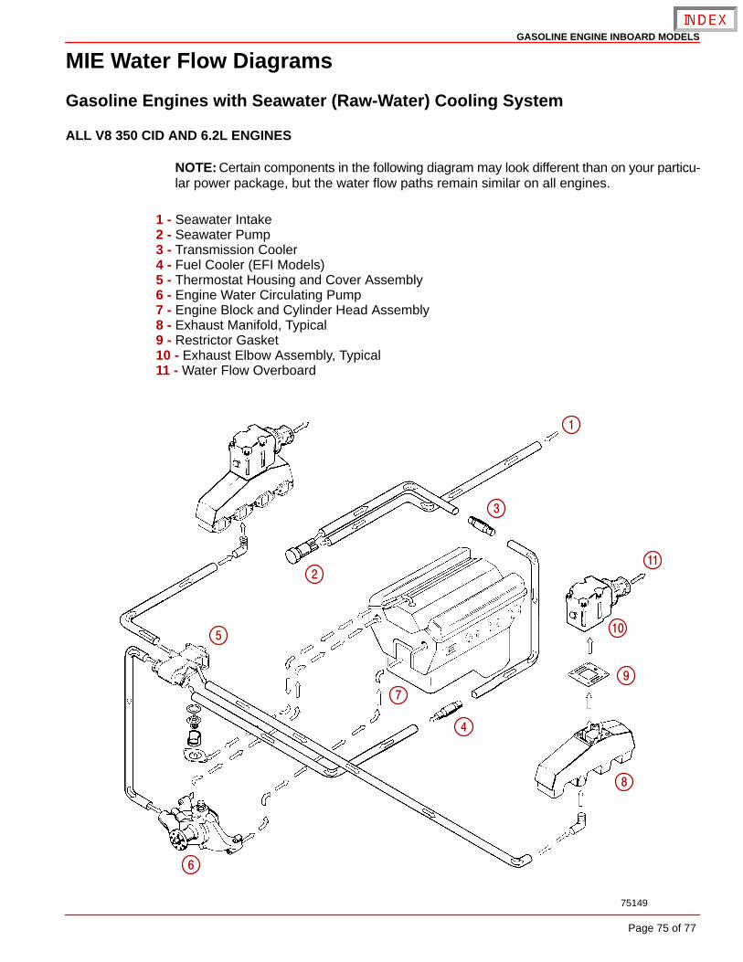
75149
�
�
�
�
�
�
�
�
�
��
GASOLINE ENGINE INBOARD MODELS
Page 75 of 77
MIE Water Flow Diagrams
Gasoline Engines with Seawater (Raw-Water) Cooling System
ALL V8 350 CID AND 6.2L ENGINES
NOTE: Certain components in the following diagram may look different than on your particu-lar power package, but the water flow paths remain similar on all engines.
1 - Seawater Intake2 - Seawater Pump3 - Transmission Cooler4 - Fuel Cooler (EFI Models)5 - Thermostat Housing and Cover Assembly6 - Engine Water Circulating Pump7 - Engine Block and Cylinder Head Assembly8 - Exhaust Manifold, Typical9 - Restrictor Gasket10 - Exhaust Elbow Assembly, Typical11 - Water Flow Overboard
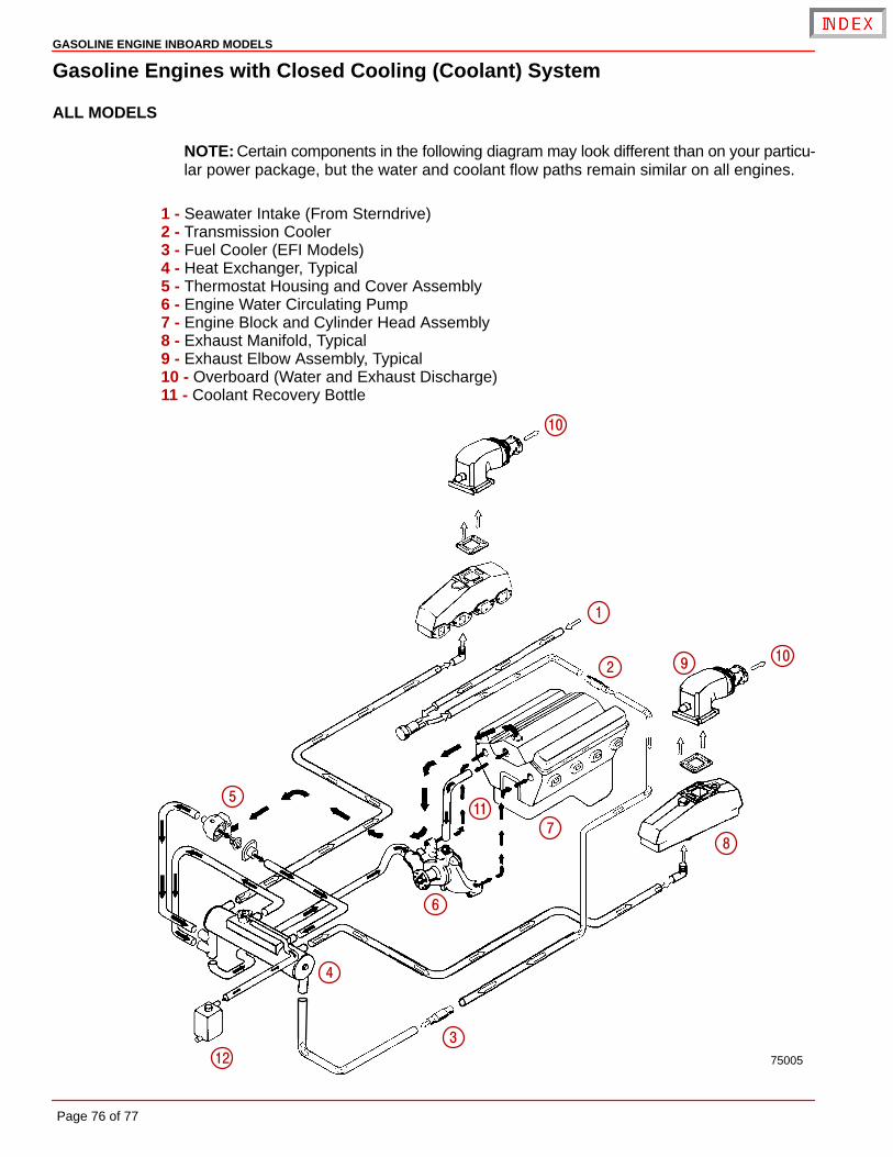
75005
�
�
�
�
�
�
�
�
�
��
��
�
GASOLINE ENGINE INBOARD MODELS
Page 76 of 77
Gasoline Engines with Closed Cooling (Coolant) System
ALL MODELS
NOTE: Certain components in the following diagram may look different than on your particu-lar power package, but the water and coolant flow paths remain similar on all engines.
1 - Seawater Intake (From Sterndrive)2 - Transmission Cooler3 - Fuel Cooler (EFI Models)4 - Heat Exchanger, Typical5 - Thermostat Housing and Cover Assembly6 - Engine Water Circulating Pump7 - Engine Block and Cylinder Head Assembly8 - Exhaust Manifold, Typical9 - Exhaust Elbow Assembly, Typical10 - Overboard (Water and Exhaust Discharge)11 - Coolant Recovery Bottle

GASOLINE ENGINE INBOARD MODELS
Page 77 of 77
Predelivery InspectionNot Check/Applicable Adjust
Not Check/Applicable Adjust
CHECK BEFORE RUNNING ON THE WATER TESTDrain plug in and petcocks Engine alignment (Inboards only)closed
Seawater inlet valve open Starter neutral safety switch operation
Engine mounts tightWater pump operation
Engine alignmentInstruments(s) operation
Drive unit fasteners torquedFuel leaks
Power trim cylinders fastenerstight Oil leaksBattery fully charged and secured
Water leaksAll electrical connections tight
Exhaust leaksExhaust system hose clampstight Ignition timingAll fuel connections tight
Idle RPM, within specificationsCorrect rotation propeller(installed and torqued)Throttle, shift and steering system Forward - Neutral - Reversefasteners tightened properly gear operationThrottle plates open and close Steering operation throughoutcompletely rangeCrankcase oil level Acceleration from idle rpm
Power trim oil level WOT RPM withinspecifications (in forward gear)
Stern drive unit oil levelPower trim operation
Power steering fluid levelTrim tab adjustment
Closed cooling levelBoat handling
Transmission fluid levelAFTER ON WATER TEST
Alternator belt tensionPropeller nut torque
Seawater pickup pump belttension
Fuel, oil, coolant, water and fluidPower steering pump belt tension leaks
Audio warning system operation Oil and fluid levels
Apply Quicksilver Corrosion Guard toengine package