gas boiler controls wiring & application guide · can improve heating system operation, reduce...
TRANSCRIPT

Gas Boiler Wiring & Application GuideU.S. Boiler Company
08/23/131
Gas Boiler ControlsWiring & Application Guide
Featuring Burnham® Brand IQ Boiler Controland Intelligent Hydronic Control Systems
ES2™ ESC™ Series 3™ Series 2™
boilercontrol
IntelligentHydronic Control
©2013 U.S. Boiler Company
Gas Boiler Wiring & Application GuideU.S. Boiler Company
08/23/132
Table of Contents1.0 Introduction ........................................................................................................................... 3
2.0 IQ Gas Boiler Control System .......................................................................................................................................... 4 2.1 Single Zone Heating ............................................................................................................................................... 5 2.2 Single Zone Heating, Power Stealing Thermostat ................................................................................................... 6 2.3 Single Zone Heating, IWH w/TPI Control ................................................................................................................ 7 2.4 Single Zone Heating, IWH w/Aquastat Control ....................................................................................................... 8 2.5 Two Zone Heating .................................................................................................................................................. 9 2.6 Zone Valves Heating ............................................................................................................................................. 10 2.7 Zone Valves Heating, IWH w/TPI Control, 2 Circulators ....................................................................................... 11 2.8 Zone Valves Heating, IWH w/Aquastat Control, 2 Circulators ............................................................................... 12 2.9 Zone Valves Heating, IWH w/TPI Control, 1 Circulators, No Priority .................................................................... 13 2.10 Zone Valves Heating, IWH w/Aquastat Control, 1 Circulators, No Priority ............................................................ 14 2.11 Zone Valve Control Heating, IWH w/TPI Control, 2 Circulator .............................................................................. 15 2.12 Zone Valve Control Heating, IWH w/Aquastat Control, 2 Circulator ...................................................................... 16 2.13 Zone Valve Control Heating, IWH w/TPI Control, 1 Circulator .............................................................................. 17 2.14 Zone Valve Control Heating, IWH w/Aquastat Control, 1 Circulator ...................................................................... 18 2.15 Zone Switching Relay Heating .............................................................................................................................. 19 2.16 Zone Switching Relay Heating, IWH w/TPI Control .............................................................................................. 20 2.17 Zone Switching Relay Heating, IWH w/Aquastat Control ...................................................................................... 21
3.0 IQ Gas Boiler Control System, Outdoor Reset Card .................................................................................................22-24 3.1 Single Zone Heating ............................................................................................................................................. 25 3.2 Single Zone Heating, IWH w/TPI Control .............................................................................................................. 26 3.3 Single Zone Heating, IWH w/Aquastat Control ..................................................................................................... 27 3.4 Zone Valves Heating, IWH w/TPI Control, 2 Circulators ....................................................................................... 28 3.5 Zone Valves Heating, IWH w/Aquastat Control, 2 Circulators ............................................................................... 29 3.6 Zone Valves Heating, IWH w/TPI Control, 1 Circulators, No Priority .................................................................... 30 3.7 Zone Valves Heating, IWH w/Aquastat Control, 1 Circulators, No Priority ............................................................ 31 3.8 Zone Valve Control Heating, IWH w/TPI Control, 2 Circulator .............................................................................. 32 3.9 Zone Valve Control Heating, IWH w/Aquastat Control, 2 Circulator ...................................................................... 33 3.10 Zone Valve Control Heating, IWH w/TPI Control, 1 Circulator .............................................................................. 34 3.11 Zone Valve Control Heating, IWH w/Aquastat Control, 1 Circulator ..................................................................... 35 3.12 Zone Switching Relay Heating, IWH w/TPI Control .............................................................................................. 36 3.13 Zone Switching Relay Heating, IWH w/Aquastat Control ...................................................................................... 37
4.0 Intelligent Hydronic Control (IHC) Series 2 & PVG Boilers Only 4.1 Single Zone Heating ............................................................................................................................................. 38 4.2 Single Zone Heating, Power Stealing Thermostat ................................................................................................. 38 4.3 Single Zone Heating, Indirect Water Heater (IWH) w/TPI Control ......................................................................... 39 4.4 Single Zone Heating, IWH w/Aquastat Control ..................................................................................................... 40 4.5 Two Zones Heating ............................................................................................................................................... 41 4.6 Zone Valves Heating ............................................................................................................................................. 42 4.7 Zone Valves Heating, IWH w/TPI Control, 2 Circulators ....................................................................................... 43 4.8 Zone Valves Heating, IWH w/Aquastat Control, 2 Circulators ............................................................................... 44 4.9 Zone Valves Heating, IWH w/TPI Control, 1 Circulators, No Priority .................................................................... 45 4.10 Zone Valves Heating, IWH w/Aquastat Control, 1 Circulators, No Priority ............................................................ 46 4.11 Zone Valve Control Heating, IWH w/TPI Control, 2 Circulator .............................................................................. 47 4.12 Zone Valve Control Heating, IWH w/Aquastat Control, 2 Circulator ...................................................................... 48 4.13 Zone Valve Control Heating, IWH w/TPI Control, 1 Circulator .............................................................................. 49 4.14 Zone Valve Control Heating, IWH w/Aquastat Control, 1 Circulator ...................................................................... 50 4.15 Zone Switching Relay Heating .............................................................................................................................. 51 4.16 Zone Switching Relay Heating, IWH w/TPI Control .............................................................................................. 52 4.17 Zone Switching Relay Heating, IWH w/Aquastat Control ...................................................................................... 53
Gas Boiler Wiring & Application GuideU.S. Boiler Company
08/23/133
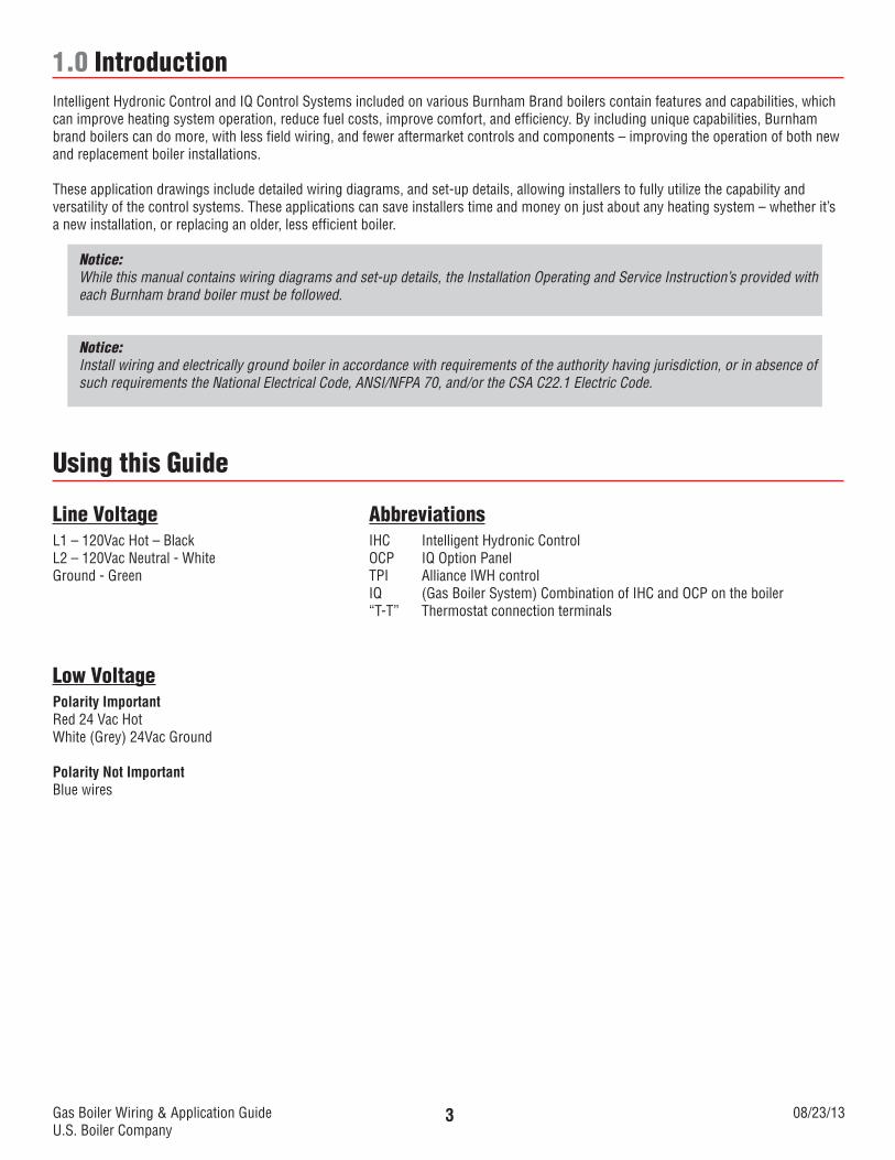
1.0 Introduction Intelligent Hydronic Control and IQ Control Systems included on various Burnham Brand boilers contain features and capabilities, which can improve heating system operation, reduce fuel costs, improve comfort, and efficiency. By including unique capabilities, Burnham brand boilers can do more, with less field wiring, and fewer aftermarket controls and components – improving the operation of both new and replacement boiler installations.
These application drawings include detailed wiring diagrams, and set-up details, allowing installers to fully utilize the capability and versatility of the control systems. These applications can save installers time and money on just about any heating system – whether it’s a new installation, or replacing an older, less efficient boiler.
Notice:While this manual contains wiring diagrams and set-up details, the Installation Operating and Service Instruction’s provided with each Burnham brand boiler must be followed.
Notice:Install wiring and electrically ground boiler in accordance with requirements of the authority having jurisdiction, or in absence of such requirements the National Electrical Code, ANSI/NFPA 70, and/or the CSA C22.1 Electric Code.
Using this Guide
Line Voltage AbbreviationsL1 – 120Vac Hot – Black IHC Intelligent Hydronic ControlL2 – 120Vac Neutral - White OCP IQ Option PanelGround - Green TPI Alliance IWH control IQ (Gas Boiler System) Combination of IHC and OCP on the boiler “T-T” Thermostat connection terminals
Low Voltage Polarity Important Red 24 Vac HotWhite (Grey) 24Vac Ground
Polarity Not ImportantBlue wires
Gas Boiler Wiring & Application GuideU.S. Boiler Company
08/23/134
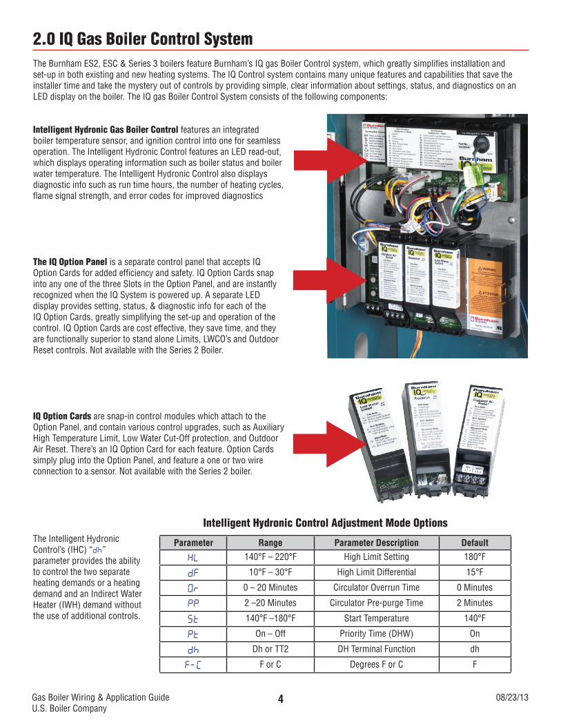
2.0 IQ Gas Boiler Control SystemThe Burnham ES2, ESC & Series 3 boilers feature Burnham’s IQ gas Boiler Control system, which greatly simplifies installation and set-up in both existing and new heating systems. The IQ Control system contains many unique features and capabilities that save the installer time and take the mystery out of controls by providing simple, clear information about settings, status, and diagnostics on an LED display on the boiler. The IQ gas Boiler Control System consists of the following components:
Intelligent Hydronic Gas Boiler Control features an integrated boiler temperature sensor, and ignition control into one for seamless operation. The Intelligent Hydronic Control features an LED read-out, which displays operating information such as boiler status and boiler water temperature. The Intelligent Hydronic Control also displays diagnostic info such as run time hours, the number of heating cycles, flame signal strength, and error codes for improved diagnostics
The IQ Option Panel is a separate control panel that accepts IQ Option Cards for added efficiency and safety. IQ Option Cards snap into any one of the three Slots in the Option Panel, and are instantly recognized when the IQ System is powered up. A separate LED display provides setting, status, & diagnostic info for each of the IQ Option Cards, greatly simplifying the set-up and operation of the control. IQ Option Cards are cost effective, they save time, and they are functionally superior to stand alone Limits, LWCO’s and Outdoor Reset controls. Not available with the Series 2 Boiler.
IQ Option Cards are snap-in control modules which attach to the Option Panel, and contain various control upgrades, such as Auxiliary High Temperature Limit, Low Water Cut-Off protection, and Outdoor Air Reset. There’s an IQ Option Card for each feature. Option Cards simply plug into the Option Panel, and feature a one or two wire connection to a sensor. Not available with the Series 2 boiler.
Parameter Range Parameter Description Default
HL 140°F – 220°F High Limit Setting 180°F
dF 10°F – 30°F High Limit Differential 15°F
Or 0 – 20 Minutes Circulator Overrun Time 0 Minutes
PP 2 –20 Minutes Circulator Pre-purge Time 2 Minutes
St 140°F –180°F Start Temperature 140°F
Pt On – Off Priority Time (DHW) On
dh Dh or TT2 DH Terminal Function dh
F-C F or C Degrees F or C F
Intelligent Hydronic Control Adjustment Mode OptionsThe Intelligent Hydronic Control’s (IHC) “Dh” parameter provides the ability to control the two separate heating demands or a heating demand and an Indirect Water Heater (IWH) demand without the use of additional controls.
Gas Boiler Wiring & Application GuideU.S. Boiler Company
08/23/135
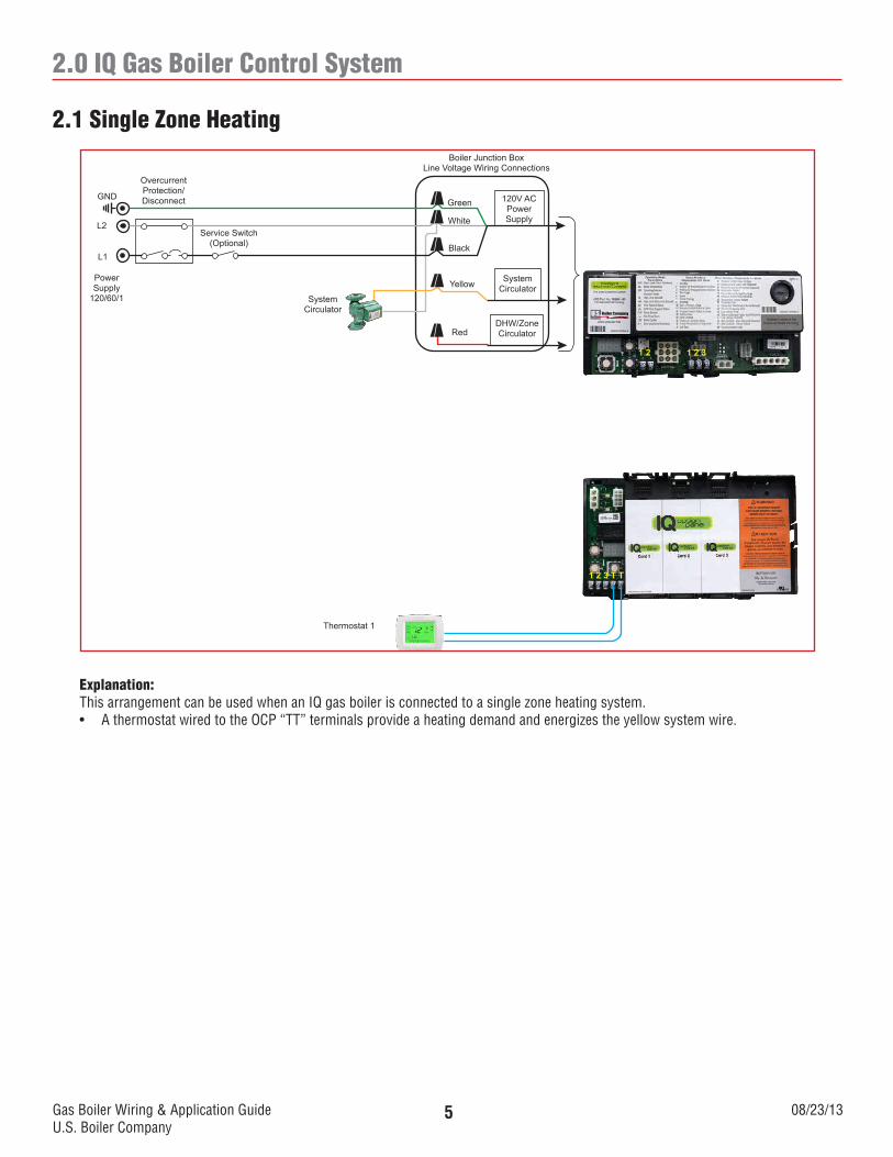
2.0 IQ Gas Boiler Control System
120V ACPowerSupply
SystemCirculator
DHW/ZoneCirculator
Boiler Junction BoxLine Voltage Wiring Connections
Green
White
Black
Yellow
SystemCirculator
Service Switch(Optional)
OvercurrentProtection/DisconnectGND
L2
L1
PowerSupply
120/60/1
Thermostat 1
1 2 3 T T
1 2 1 2 3
Red
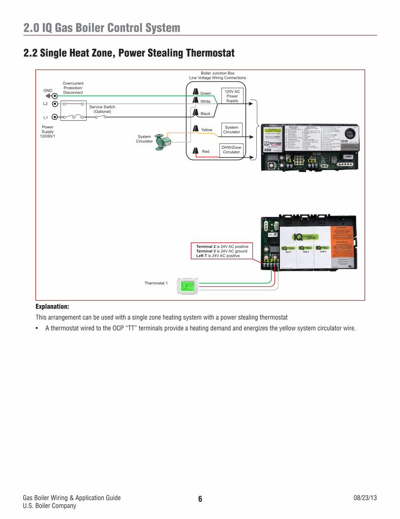
Explanation:This arrangement can be used when an IQ gas boiler is connected to a single zone heating system.• AthermostatwiredtotheOCP“TT”terminalsprovideaheatingdemandandenergizestheyellowsystemwire.
2.1 Single Zone Heating
Gas Boiler Wiring & Application GuideU.S. Boiler Company
08/23/136
2.0 IQ Gas Boiler Control System
Explanation:
This arrangement can be used with a single zone heating system with a power stealing thermostat
• AthermostatwiredtotheOCP“TT”terminalsprovideaheatingdemandandenergizestheyellowsystemcirculatorwire.
2.2 Single Heat Zone, Power Stealing Thermostat
120V ACPowerSupply
SystemCirculator
DHW/ZoneCirculator
Boiler Junction BoxLine Voltage Wiring Connections
Green
White
Black
Yellow
SystemCirculator
Service Switch(Optional)
OvercurrentProtection/DisconnectGND
L2
L1
PowerSupply
120/60/1
Thermostat 1
1 2 3 T T
1 2 1 2 3
Red
Terminal 2 is 24V AC positiveTerminal 3 is 24V AC groundLeft T is 24V AC positive
Gas Boiler Wiring & Application GuideU.S. Boiler Company
08/23/137
2.0 IQ Gas Boiler Control System
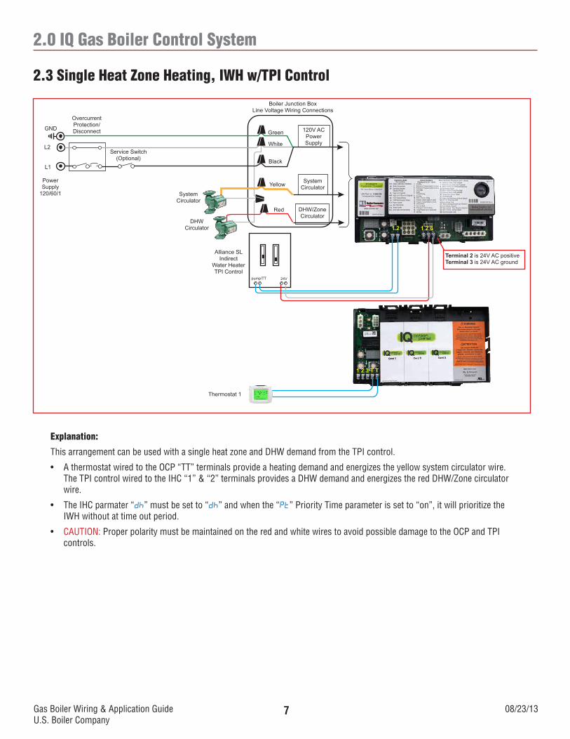
Explanation:
This arrangement can be used with a single heat zone and DHW demand from the TPI control.
• AthermostatwiredtotheOCP“TT”terminalsprovideaheatingdemandandenergizestheyellowsystemcirculatorwire.The TPI control wired to the IHC “1” & “2” terminals provides a DHW demand and energizes the red DHW/Zone circulator wire.
• TheIHCparmater“dh” must be set to “dh” and when the “Pt” Priority Time parameter is set to “on”, it will prioritize the IWH without at time out period.
• CAUTION: Proper polarity must be maintained on the red and white wires to avoid possible damage to the OCP and TPI controls.
2.3 Single Heat Zone Heating, IWH w/TPI Control
120V ACPowerSupply
SystemCirculator
DHW/ZoneCirculator
Boiler Junction BoxLine Voltage Wiring Connections
Green
White
Black
Yellow
SystemCirculator
Service Switch(Optional)
OvercurrentProtection/DisconnectGND
L2
L1
PowerSupply
120/60/1
Alliance SLIndirect
Water HeaterTPI Control
1 2 3 T T
1 2 1 2 3
Red
DHWCirculator
Terminal 2 is 24V AC positiveTerminal 3 is 24V AC ground
Thermostat 1
24Vpump/TT
Gas Boiler Wiring & Application GuideU.S. Boiler Company
08/23/138
2.0 IQ Gas Boiler Control System
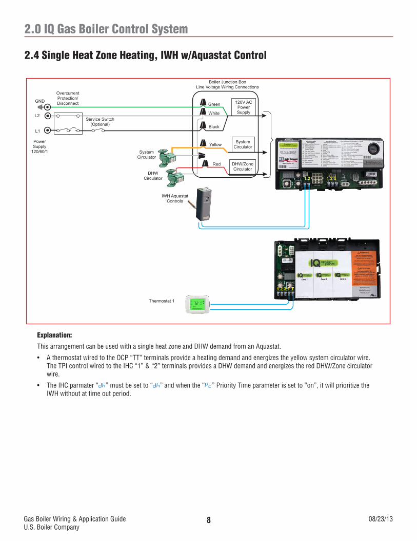
Explanation:
This arrangement can be used with a single heat zone and DHW demand from an Aquastat.
• AthermostatwiredtotheOCP“TT”terminalsprovideaheatingdemandandenergizestheyellowsystemcirculatorwire.The TPI control wired to the IHC “1” & “2” terminals provides a DHW demand and energizes the red DHW/Zone circulator wire.
• TheIHCparmater“dh” must be set to “dh” and when the “Pt” Priority Time parameter is set to “on”, it will prioritize the IWH without at time out period.
2.4 Single Heat Zone Heating, IWH w/Aquastat Control
120V ACPowerSupply
SystemCirculator
DHW/ZoneCirculator
Boiler Junction BoxLine Voltage Wiring Connections
Green
White
Black
Yellow
SystemCirculator
Service Switch(Optional)
OvercurrentProtection/DisconnectGND
L2
L1
PowerSupply
120/60/1
Thermostat 1
IWH Aquastat Controls
1 2 3 T T
1 2 1 2 3
Red
DHWCirculator
Gas Boiler Wiring & Application GuideU.S. Boiler Company
08/23/139
2.0 IQ Gas Boiler Control System
Explanation:
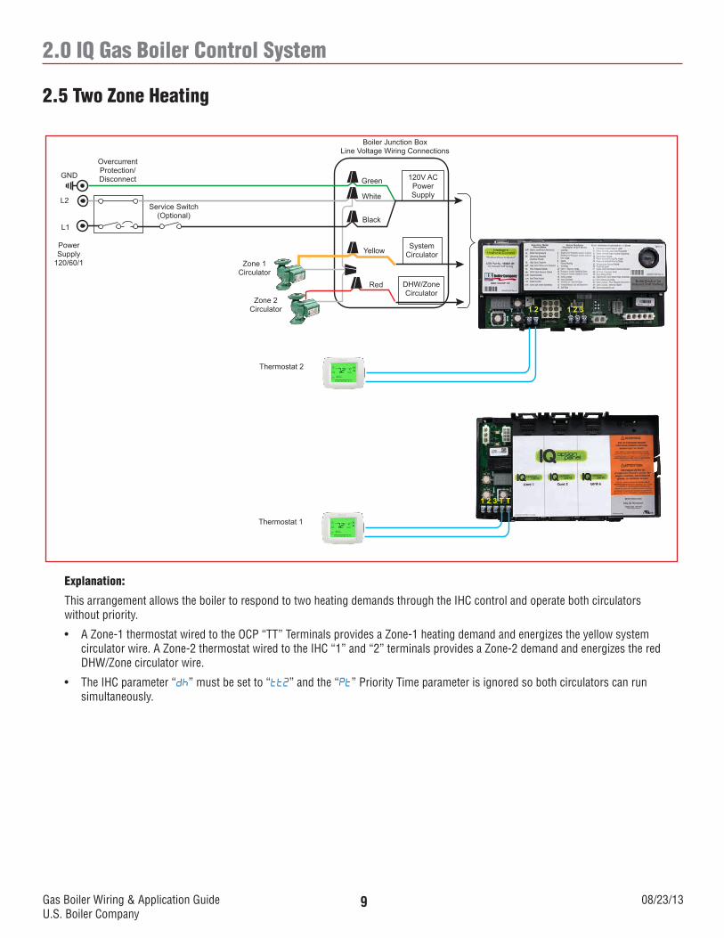
This arrangement allows the boiler to respond to two heating demands through the IHC control and operate both circulators without priority.
• AZone-1thermostatwiredtotheOCP“TT”TerminalsprovidesaZone-1heatingdemandandenergizestheyellowsystemcirculator wire. A Zone-2 thermostat wired to the IHC “1” and “2” terminals provides a Zone-2 demand and energizes the red DHW/Zone circulator wire.
• TheIHCparameter“dh” must be set to “tt2” and the “Pt” Priority Time parameter is ignored so both circulators can run simultaneously.
2.5 Two Zone Heating
120V ACPowerSupply
SystemCirculator
DHW/ZoneCirculator
Boiler Junction BoxLine Voltage Wiring Connections
Green
White
Black
Yellow
Zone 1Circulator
Service Switch(Optional)
OvercurrentProtection/DisconnectGND
L2
L1
PowerSupply
120/60/1
Thermostat 1
1 2 3 T T
1 2 1 2 3
Red
Zone 2Circulator
Thermostat 2
Gas Boiler Wiring & Application GuideU.S. Boiler Company
08/23/1310
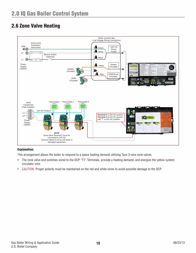
2.0 IQ Gas Boiler Control System
Explanation:
This arrangement allows the boiler to respond to a space heating demand utilizing Taco 3-wire zone valves.
• ThezonevalveendswitcheswiredtotheOCP“TT”Terminals,provideaheatingdemand,andenergizetheyellowsystemcirculator wire.
• CAUTION: Proper polarity must be maintained on the red and white wires to avoid possible damage to the OCP.
2.6 Zone Valve Heating
120V ACPowerSupply
SystemCirculator
DHW/ZoneCirculator
Boiler Junction BoxLine Voltage Wiring Connections
Green
White
Black
Yellow
SystemCirculator
Service Switch(Optional)
OvercurrentProtection/DisconnectGND
L2
L1
PowerSupply
120/60/1
Thermostat 3
1 2 3 T T
1 2 1 2 3
Red
DHWCirculator
Terminal 2 is 24V AC positiveTerminal 3 is 24V AC groundLeft “T” is 24V AC positive
Thermostat 2Thermostat 1
24V AC Positive
40VA Transformer
Field Installed
Power Supply
120/60/1
L1L2
NOTEZone Valve Terminal 2 must be
connected to 24V ACCommon failure to do so will result in
damaged equipment
Gas Boiler Wiring & Application GuideU.S. Boiler Company
08/23/1311
2.0 IQ Gas Boiler Control System
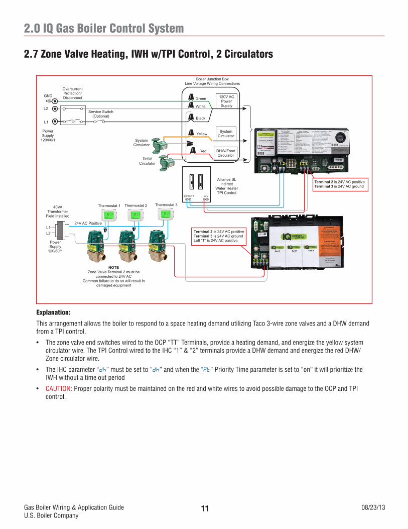
Explanation:
This arrangement allows the boiler to respond to a space heating demand utilizing Taco 3-wire zone valves and a DHW demand from a TPI control.
• ThezonevalveendswitcheswiredtotheOCP“TT”Terminals,provideaheatingdemand,andenergizetheyellowsystemcirculator wire. The TPI Control wired to the IHC “1” & “2” terminals provide a DHW demand and energize the red DHW/Zone circulator wire.
• TheIHCparameter“dh” must be set to “dh” and when the “Pt” Priority Time parameter is set to “on” it will prioritize the IWH without a time out period
• CAUTION: Proper polarity must be maintained on the red and white wires to avoid possible damage to the OCP and TPI control.
2.7 Zone Valve Heating, IWH w/TPI Control, 2 Circulators
120V ACPowerSupply
SystemCirculator
DHW/ZoneCirculator
Boiler Junction BoxLine Voltage Wiring Connections
Green
White
Black
Yellow
SystemCirculator
Service Switch(Optional)
OvercurrentProtection/DisconnectGND
L2
L1
PowerSupply
120/60/1
Thermostat 3
1 2 3 T T
1 2 1 2 3
Red
DHWCirculator
Terminal 2 is 24V AC positiveTerminal 3 is 24V AC groundLeft “T” is 24V AC positive
Thermostat 2Thermostat 1
24V AC Positive
40VA Transformer
Field Installed
Power Supply
120/60/1
L1L2
NOTEZone Valve Terminal 2 must be
connected to 24V ACCommon failure to do so will result in
damaged equipment
Alliance SLIndirect
Water HeaterTPI Control
Terminal 2 is 24V AC positiveTerminal 3 is 24V AC ground
24Vpump/TT
Gas Boiler Wiring & Application GuideU.S. Boiler Company
08/23/1312
2.0 IQ Gas Boiler Control System
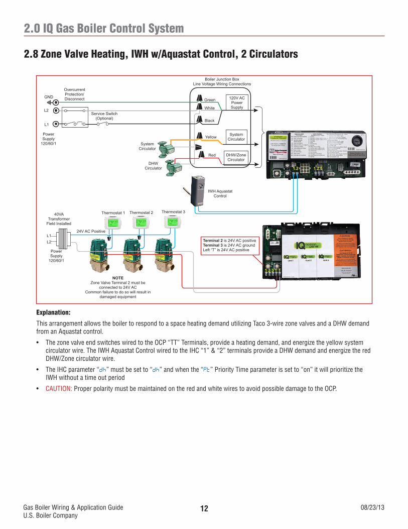
Explanation:
This arrangement allows the boiler to respond to a space heating demand utilizing Taco 3-wire zone valves and a DHW demand from an Aquastat control.
• ThezonevalveendswitcheswiredtotheOCP“TT”Terminals,provideaheatingdemand,andenergizetheyellowsystemcirculator wire. The IWH Aquastat Control wired to the IHC “1” & “2” terminals provide a DHW demand and energize the red DHW/Zone circulator wire.
• TheIHCparameter“dh” must be set to “dh” and when the “Pt” Priority Time parameter is set to “on” it will prioritize the IWH without a time out period
• CAUTION: Proper polarity must be maintained on the red and white wires to avoid possible damage to the OCP.
2.8 Zone Valve Heating, IWH w/Aquastat Control, 2 Circulators
120V ACPowerSupply
SystemCirculator
DHW/ZoneCirculator
Boiler Junction BoxLine Voltage Wiring Connections
Green
White
Black
Yellow
SystemCirculator
Service Switch(Optional)
OvercurrentProtection/DisconnectGND
L2
L1
PowerSupply
120/60/1
Thermostat 3
1 2 3 T T
1 2 1 2 3
Red
DHWCirculator
Terminal 2 is 24V AC positiveTerminal 3 is 24V AC groundLeft “T” is 24V AC positive
Thermostat 2Thermostat 1
24V AC Positive
40VA Transformer
Field Installed
Power Supply
120/60/1
L1L2
NOTEZone Valve Terminal 2 must be
connected to 24V ACCommon failure to do so will result in
damaged equipment
IWH Aquastat Control

Gas Boiler Wiring & Application GuideU.S. Boiler Company
08/23/1313
2.0 IQ Gas Boiler Control System
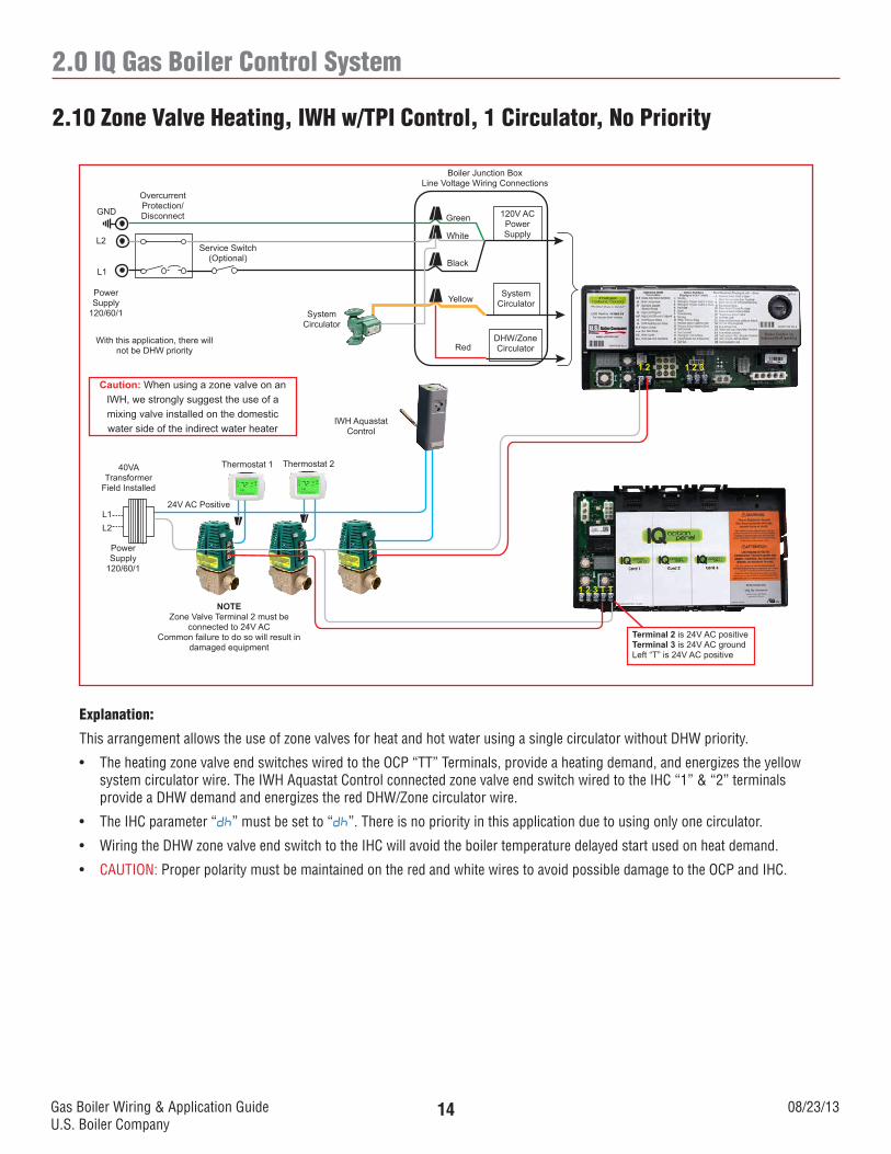
Explanation:
This arrangement allows the use of zone valves for heat and hot water using a single circulator without DHW priority.
• TheheatingzonevalveendswitcheswiredtotheOCP“TT”Terminals,provideaheatingdemand,andenergizetheyellowsystem circulator wire. The TPI Control connected zone valve end switch wired to the IHC “1” & “2” terminals provide a DHW demand and energizes the red DHW/Zone circulator wire.
• TheIHCparameter“dh” must be set to “dh”. There is no priority in this application due to using only one circulator
• WiringtheDHWzonevalveendswitchtotheIHCwillavoidtheboilertemperaturedelayedstartusedonheatdemand
• CAUTION: Proper polarity must be maintained on the red and white wires to avoid possible damage to the OCP and TPI control.
2.9 Zone Valve Heating, IWH w/TPI Control, 1 Circulator, No Priority
120V ACPowerSupply
SystemCirculator
DHW/ZoneCirculator
Boiler Junction BoxLine Voltage Wiring Connections
Green
White
Black
Yellow
SystemCirculator
Service Switch(Optional)
OvercurrentProtection/DisconnectGND
L2
L1
PowerSupply
120/60/1
1 2 3 T T
1 2 1 2 3
Red
Thermostat 2Thermostat 1
24V AC Positive
40VA Transformer
Field Installed
Power Supply
120/60/1
L1L2
NOTEZone Valve Terminal 2 must be
connected to 24V ACCommon failure to do so will result in
damaged equipment
Alliance SLIndirect
Water HeaterTPI Control
Caution: When using a zone valve on an IWH, we strongly suggest the use of a mixing valve installed on the domestic water side of the indirect water heater
SystemCirculator
With this application, there will not be DHW priority
Terminal 2 is 24V AC positiveTerminal 3 is 24V AC groundLeft “T” is 24V AC positive
Terminal 2 is 24V AC positiveTerminal 3 is 24V AC ground
24Vpump/TT
Gas Boiler Wiring & Application GuideU.S. Boiler Company
08/23/1314
2.0 IQ Gas Boiler Control System
Explanation:
This arrangement allows the use of zone valves for heat and hot water using a single circulator without DHW priority.
• TheheatingzonevalveendswitcheswiredtotheOCP“TT”Terminals,provideaheatingdemand,andenergizestheyellowsystem circulator wire. The IWH Aquastat Control connected zone valve end switch wired to the IHC “1” & “2” terminals provide a DHW demand and energizes the red DHW/Zone circulator wire.
• TheIHCparameter“dh” must be set to “dh”. There is no priority in this application due to using only one circulator.
• WiringtheDHWzonevalveendswitchtotheIHCwillavoidtheboilertemperaturedelayedstartusedonheatdemand.
• CAUTION: Proper polarity must be maintained on the red and white wires to avoid possible damage to the OCP and IHC.
2.10 Zone Valve Heating, IWH w/TPI Control, 1 Circulator, No Priority
120V ACPowerSupply
SystemCirculator
DHW/ZoneCirculator
Boiler Junction BoxLine Voltage Wiring Connections
Green
White
Black
Yellow
SystemCirculator
Service Switch(Optional)
OvercurrentProtection/DisconnectGND
L2
L1
PowerSupply
120/60/1
1 2 3 T T
1 2 1 2 3
Red
Terminal 2 is 24V AC positiveTerminal 3 is 24V AC groundLeft “T” is 24V AC positive
Thermostat 2Thermostat 1
24V AC Positive
40VA Transformer
Field Installed
Power Supply
120/60/1
L1L2
NOTEZone Valve Terminal 2 must be
connected to 24V ACCommon failure to do so will result in
damaged equipment
IWH Aquastat Control
Caution: When using a zone valve on an IWH, we strongly suggest the use of a mixing valve installed on the domestic water side of the indirect water heater
With this application, there will not be DHW priority
Gas Boiler Wiring & Application GuideU.S. Boiler Company
08/23/1315
2.0 IQ Gas Boiler Control System
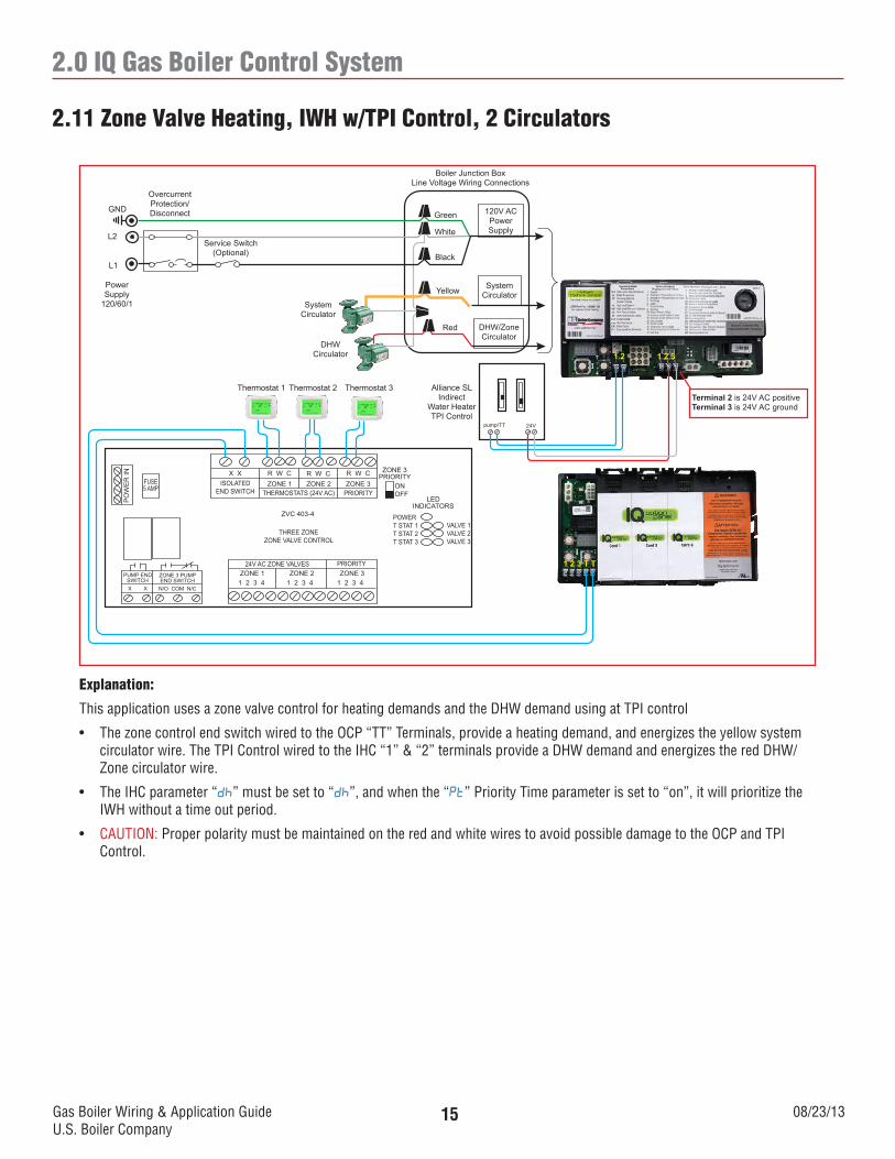
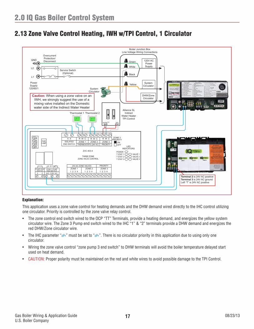
Explanation:
This application uses a zone valve control for heating demands and the DHW demand using at TPI control
• ThezonecontrolendswitchwiredtotheOCP“TT”Terminals,provideaheatingdemand,andenergizestheyellowsystemcirculator wire. The TPI Control wired to the IHC “1” & “2” terminals provide a DHW demand and energizes the red DHW/Zone circulator wire.
• TheIHCparameter“dh” must be set to “dh”, and when the “Pt” Priority Time parameter is set to “on”, it will prioritize the IWH without a time out period.
• CAUTION: Proper polarity must be maintained on the red and white wires to avoid possible damage to the OCP and TPI Control.
2.11 Zone Valve Heating, IWH w/TPI Control, 2 Circulators
Thermostat 1 Thermostat 2
X X R W C R W C R W CZONE 1 ZONE 2 ZONE 3
THERMOSTATS (24V AC) PRIORITYISOLATED
END SWITCH
ZVC 403-4
THREE ZONEZONE VALVE CONTROL
ZONE 1 ZONE 2 ZONE 3PRIORITY24V AC ZONE VALVES
1 2 3 4 1 2 3 41 2 3 4
ZONE 3PRIORITY
ONOFF
LEDINDICATORS
POWERT STAT 1T STAT 2T STAT 3
VALVE 1VALVE 2VALVE 3
FUSE5 AMP
PO
WE
R IN
ZONE 3 PUMPEND SWITCH
PUMP END SWITCH
N/O COM N/CX X
1 2 3 T T
1 2 1 2 3
120V ACPowerSupply
SystemCirculator
DHW/ZoneCirculator
Boiler Junction BoxLine Voltage Wiring Connections
Green
White
Black
Yellow
SystemCirculator
Service Switch(Optional)
OvercurrentProtection/DisconnectGND
L2
L1
PowerSupply
120/60/1
Red
DHWCirculator
Alliance SLIndirect
Water HeaterTPI Control
Thermostat 3Terminal 2 is 24V AC positiveTerminal 3 is 24V AC ground
24Vpump/TT
Gas Boiler Wiring & Application GuideU.S. Boiler Company
08/23/1316
2.0 IQ Gas Boiler Control System
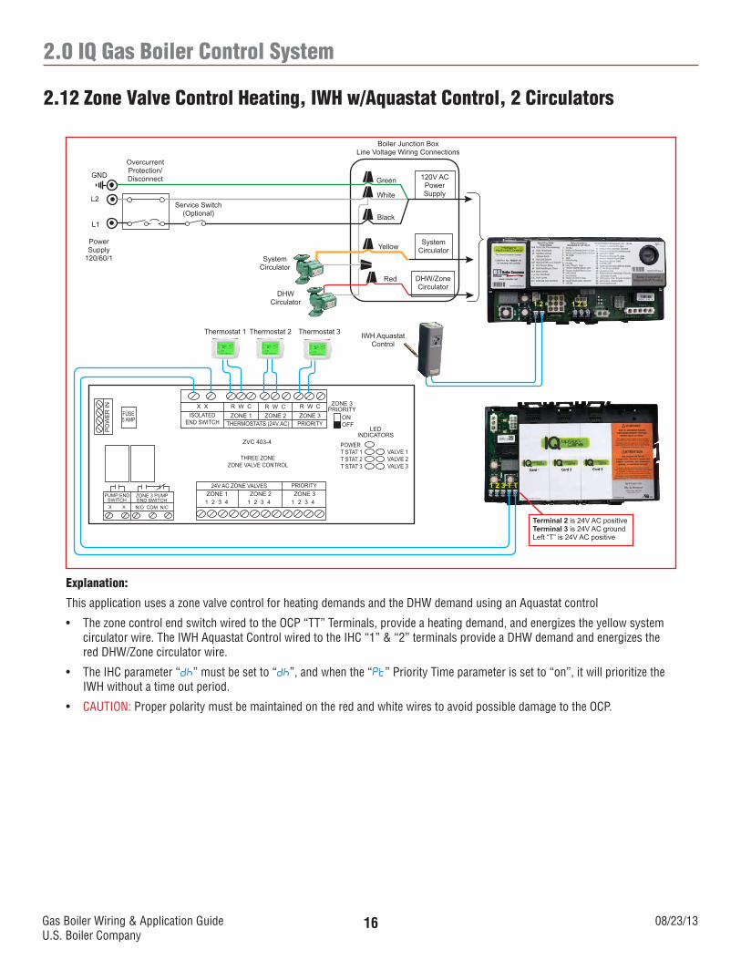
Explanation:
This application uses a zone valve control for heating demands and the DHW demand using an Aquastat control
• ThezonecontrolendswitchwiredtotheOCP“TT”Terminals,provideaheatingdemand,andenergizestheyellowsystemcirculator wire. The IWH Aquastat Control wired to the IHC “1” & “2” terminals provide a DHW demand and energizes the red DHW/Zone circulator wire.
• TheIHCparameter“dh” must be set to “dh”, and when the “Pt” Priority Time parameter is set to “on”, it will prioritize the IWH without a time out period.
• CAUTION: Proper polarity must be maintained on the red and white wires to avoid possible damage to the OCP.
2.12 Zone Valve Control Heating, IWH w/Aquastat Control, 2 Circulators
Thermostat 1 Thermostat 2
X X R W C R W C R W CZONE 1 ZONE 2 ZONE 3
THERMOSTATS (24V AC) PRIORITYISOLATED
END SWITCH
ZVC 403-4
THREE ZONEZONE VALVE CONTROL
ZONE 1 ZONE 2 ZONE 3PRIORITY24V AC ZONE VALVES
1 2 3 4 1 2 3 41 2 3 4
ZONE 3PRIORITY
ONOFF
LEDINDICATORS
POWERT STAT 1T STAT 2T STAT 3
VALVE 1VALVE 2VALVE 3
FUSE5 AMP
PO
WE
R IN
ZONE 3 PUMPEND SWITCH
PUMP END SWITCH
N/O COM N/CX X
1 2 3 T T
1 2 1 2 3
120V ACPowerSupply
SystemCirculator
DHW/ZoneCirculator
Boiler Junction BoxLine Voltage Wiring Connections
Green
White
Black
Yellow
SystemCirculator
Service Switch(Optional)
OvercurrentProtection/DisconnectGND
L2
L1
PowerSupply
120/60/1
Red
DHWCirculator
Thermostat 3 IWH Aquastat Control
Terminal 2 is 24V AC positiveTerminal 3 is 24V AC groundLeft “T” is 24V AC positive
Gas Boiler Wiring & Application GuideU.S. Boiler Company
08/23/1317
2.0 IQ Gas Boiler Control System
Explanation:
This application uses a zone valve control for heating demands and the DHW demand wired directly to the IHC control utilizing one circulator. Priority is controlled by the zone valve relay control.
• ThezonecontrolendswitchwiredtotheOCP“TT”Terminals,provideaheatingdemand,andenergizestheyellowsystemcirculator wire. The Zone 3 Pump end switch wired to the IHC “1” & “2” terminals provide a DHW demand and energizes the red DHW/Zone circulator wire.
• TheIHCparameter“dh” must be set to “dh”. There is no circulator priority in this application due to using only one circulator.
• Wiringthezonevalvecontrol“zonepump3endswitch”toDHWterminalswillavoidtheboilertemperaturedelayedstartused on heat demand.
• CAUTION: Proper polarity must be maintained on the red and white wires to avoid possible damage to the TPI Control.
2.13 Zone Valve Control Heating, IWH w/TPI Control, 1 Circulator
120V ACPowerSupply
SystemCirculator
DHW/ZoneCirculator
Boiler Junction BoxLine Voltage Wiring Connections
Green
White
Black
Yellow
SystemCirculator
Service Switch(Optional)
OvercurrentProtection/DisconnectGND
L2
L1
PowerSupply
120/60/1
Caution: When using a zone valve on an IWH, we strongly suggest the use of a mixing valve installed on the Domestic water side of the Indirect Water Heater
Thermostat 1 Thermostat 2
X X R W C R W C R W CZONE 1 ZONE 2 ZONE 3
THERMOSTATS (24V AC) PRIORITYISOLATED
END SWITCH
ZVC 403-4
THREE ZONEZONE VALVE CONTROL
ZONE 1 ZONE 2 ZONE 3PRIORITY24V AC ZONE VALVES
1 2 3 4 1 2 3 41 2 3 4
ZONE 3PRIORITY
ONOFF
LEDINDICATORS
POWERT STAT 1T STAT 2T STAT 3
VALVE 1VALVE 2VALVE 3
FUSE5 AMP
PO
WE
R IN
ZONE 3 PUMPEND SWITCH
PUMP END SWITCH
N/O COM N/CX X
1 2 3 T T
1 2 1 2 3
Alliance SLIndirect
Water HeaterTPI Control
Terminal 2 is 24V AC positiveTerminal 3 is 24V AC groundLeft “T” is 24V AC positive
24Vpump/TT
Gas Boiler Wiring & Application GuideU.S. Boiler Company
08/23/1318
2.0 IQ Gas Boiler Control System
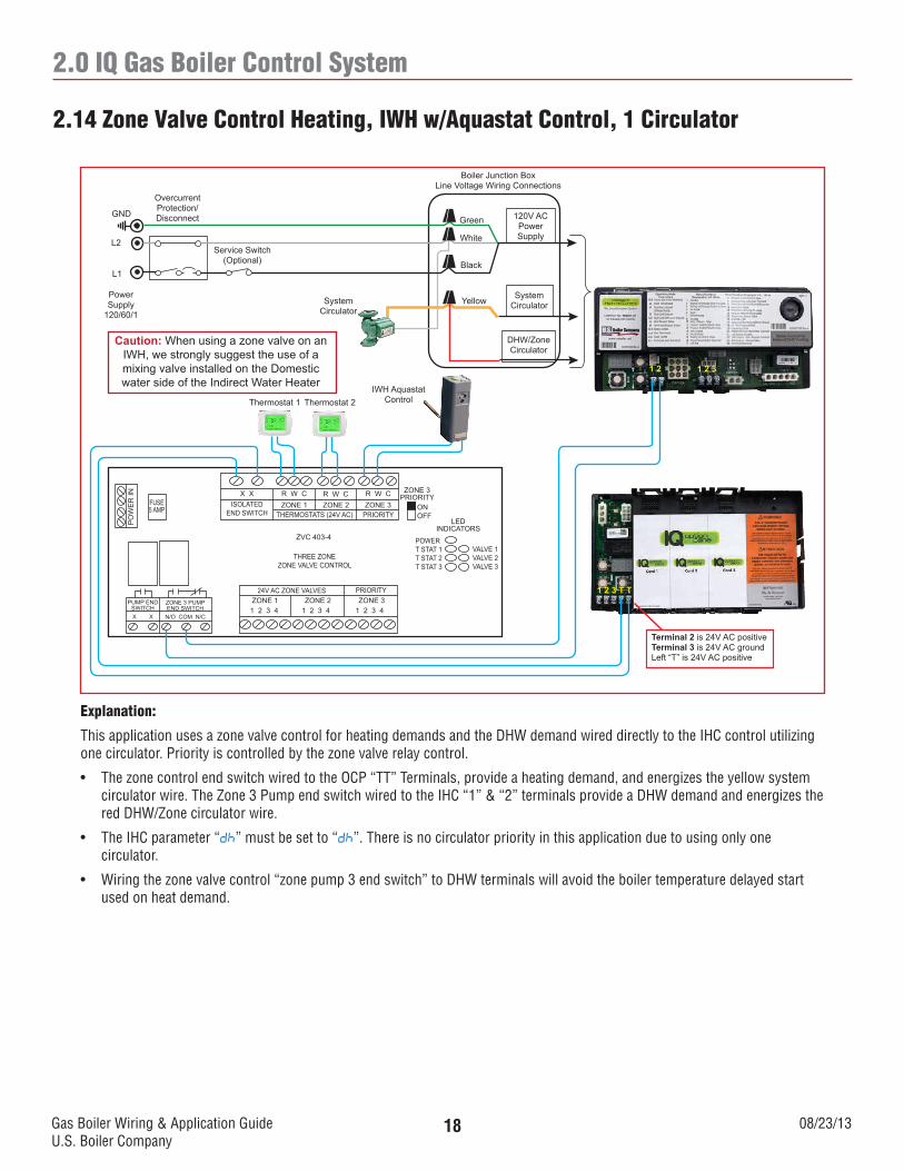
Explanation:
This application uses a zone valve control for heating demands and the DHW demand wired directly to the IHC control utilizing one circulator. Priority is controlled by the zone valve relay control.
• ThezonecontrolendswitchwiredtotheOCP“TT”Terminals,provideaheatingdemand,andenergizestheyellowsystemcirculator wire. The Zone 3 Pump end switch wired to the IHC “1” & “2” terminals provide a DHW demand and energizes the red DHW/Zone circulator wire.
• TheIHCparameter“dh” must be set to “dh”. There is no circulator priority in this application due to using only one circulator.
• Wiringthezonevalvecontrol“zonepump3endswitch”toDHWterminalswillavoidtheboilertemperaturedelayedstartused on heat demand.
2.14 Zone Valve Control Heating, IWH w/Aquastat Control, 1 Circulator
120V ACPowerSupply
SystemCirculator
DHW/ZoneCirculator
Boiler Junction BoxLine Voltage Wiring Connections
Green
White
Black
YellowSystemCirculator
Service Switch(Optional)
OvercurrentProtection/DisconnectGND
L2
L1
PowerSupply
120/60/1
Caution: When using a zone valve on an IWH, we strongly suggest the use of a mixing valve installed on the Domestic water side of the Indirect Water Heater
Thermostat 1 Thermostat 2IWH Aquastat
Control
X X R W C R W C R W CZONE 1 ZONE 2 ZONE 3
THERMOSTATS (24V AC) PRIORITYISOLATED
END SWITCH
ZVC 403-4
THREE ZONEZONE VALVE CONTROL
ZONE 1 ZONE 2 ZONE 3PRIORITY24V AC ZONE VALVES
1 2 3 4 1 2 3 41 2 3 4
ZONE 3PRIORITY
ONOFF
LEDINDICATORS
POWERT STAT 1T STAT 2T STAT 3
VALVE 1VALVE 2VALVE 3
FUSE5 AMP
PO
WE
R IN
ZONE 3 PUMPEND SWITCH
PUMP END SWITCH
N/O COM N/CX X
1 2 3 T T
1 2 1 2 3
Terminal 2 is 24V AC positiveTerminal 3 is 24V AC groundLeft “T” is 24V AC positive
Gas Boiler Wiring & Application GuideU.S. Boiler Company
08/23/1319
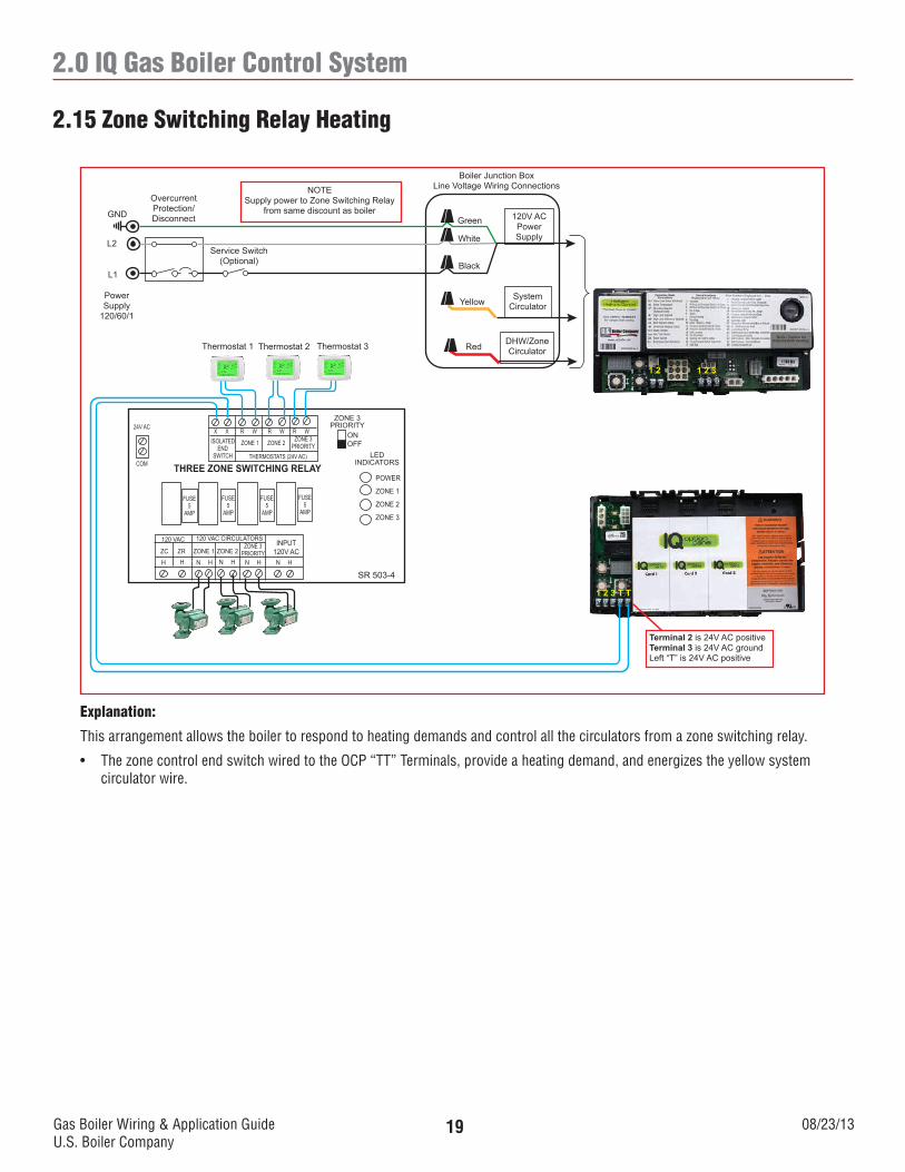
2.0 IQ Gas Boiler Control System
Explanation:
This arrangement allows the boiler to respond to heating demands and control all the circulators from a zone switching relay.
• ThezonecontrolendswitchwiredtotheOCP“TT”Terminals,provideaheatingdemand,andenergizestheyellowsystemcirculator wire.
2.15 Zone Switching Relay Heating
120V ACPowerSupply
SystemCirculator
DHW/ZoneCirculator
Boiler Junction BoxLine Voltage Wiring Connections
Green
White
Black
Yellow
Service Switch(Optional)
OvercurrentProtection/DisconnectGND
L2
L1
PowerSupply
120/60/1
Thermostat 1 Thermostat 2
ISOLATEDEND
SWITCH
SR 503-4
THREE ZONE SWITCHING RELAYLED
INDICATORS
POWER
ZONE 1
ZONE 2
ZONE 3
FUSE5
AMP
1 2 3 T T
1 2 1 2 3
Thermostat 3
X X R W R W R W
ZONE 1 ZONE 2 ZONE 3PRIORITY
THERMOSTATS (24V AC)
FUSE5
AMP
FUSE5
AMP
FUSE5
AMP
ZONE 3PRIORITY
ONOFF
24V AC
COM
INPUT120V AC
120 VAC CIRCULATORS120 VAC
ZC ZR ZONE 1 ZONE 2ZONE 3
PRIORITYH H N H N H N H N H
Red
NOTESupply power to Zone Switching Relay
from same discount as boiler
Terminal 2 is 24V AC positiveTerminal 3 is 24V AC groundLeft “T” is 24V AC positive
Gas Boiler Wiring & Application GuideU.S. Boiler Company
08/23/1320
2.0 IQ Gas Boiler Control System
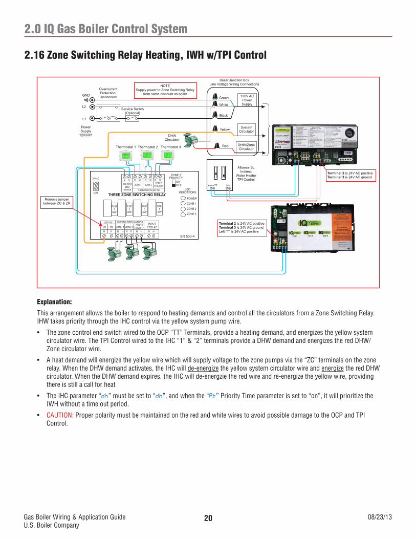
Explanation:
This arrangement allows the boiler to respond to heating demands and control all the circulators from a Zone Switching Relay. IHW takes priority through the IHC control via the yellow system pump wire.
• ThezonecontrolendswitchwiredtotheOCP“TT”Terminals,provideaheatingdemand,andenergizestheyellowsystemcirculator wire. The TPI Control wired to the IHC “1” & “2” terminals provide a DHW demand and energizes the red DHW/Zone circulator wire.
• Aheatdemandwillenergizetheyellowwirewhichwillsupplyvoltagetothezonepumpsviathe“ZC”terminalsonthezonerelay. When the DHW demand activates, the IHC will de-energize the yellow system circulator wire and energize the red DHW circulator. When the DHW demand expires, the IHC will de-energzie the red wire and re-energize the yellow wire, providing there is still a call for heat
• TheIHCparameter“dh” must be set to “dh”, and when the “Pt” Priority Time parameter is set to “on”, it will prioritize the IWH without a time out period.
• CAUTION: Proper polarity must be maintained on the red and white wires to avoid possible damage to the OCP and TPI Control.
2.16 Zone Switching Relay Heating, IWH w/TPI Control
120V ACPowerSupply
SystemCirculator
DHW/ZoneCirculator
Boiler Junction BoxLine Voltage Wiring Connections
Green
White
Black
Yellow
Service Switch(Optional)
OvercurrentProtection/DisconnectGND
L2
L1
PowerSupply
120/60/1
Thermostat 1 Thermostat 2
ISOLATEDEND
SWITCH
SR 503-4
THREE ZONE SWITCHING RELAYLED
INDICATORS
POWER
ZONE 1
ZONE 2
ZONE 3
FUSE5
AMP
1 2 3 T T
1 2 1 2 3
Thermostat 3
X X R W R W R W
ZONE 1 ZONE 2 ZONE 3PRIORITY
THERMOSTATS (24V AC)
FUSE5
AMP
FUSE5
AMP
FUSE5
AMP
ZONE 3PRIORITY
ONOFF
24V AC
COM
INPUT120V AC
120 VAC CIRCULATORS120V AC
ZC ZR ZONE 1 ZONE 2ZONE 3
PRIORITYH H N H N H N H N H
Red
NOTESupply power to Zone Switching Relay
from same discount as boiler
Alliance SLIndirect
Water HeaterTPI Control
Terminal 2 is 24V AC positiveTerminal 3 is 24V AC ground
DHWCirculator
Remove jumper between ZC & ZR
Terminal 2 is 24V AC positiveTerminal 3 is 24V AC groundLeft “T” is 24V AC positive
24Vpump/TT
Gas Boiler Wiring & Application GuideU.S. Boiler Company
08/23/1321
2.0 IQ Gas Boiler Control System
Explanation:
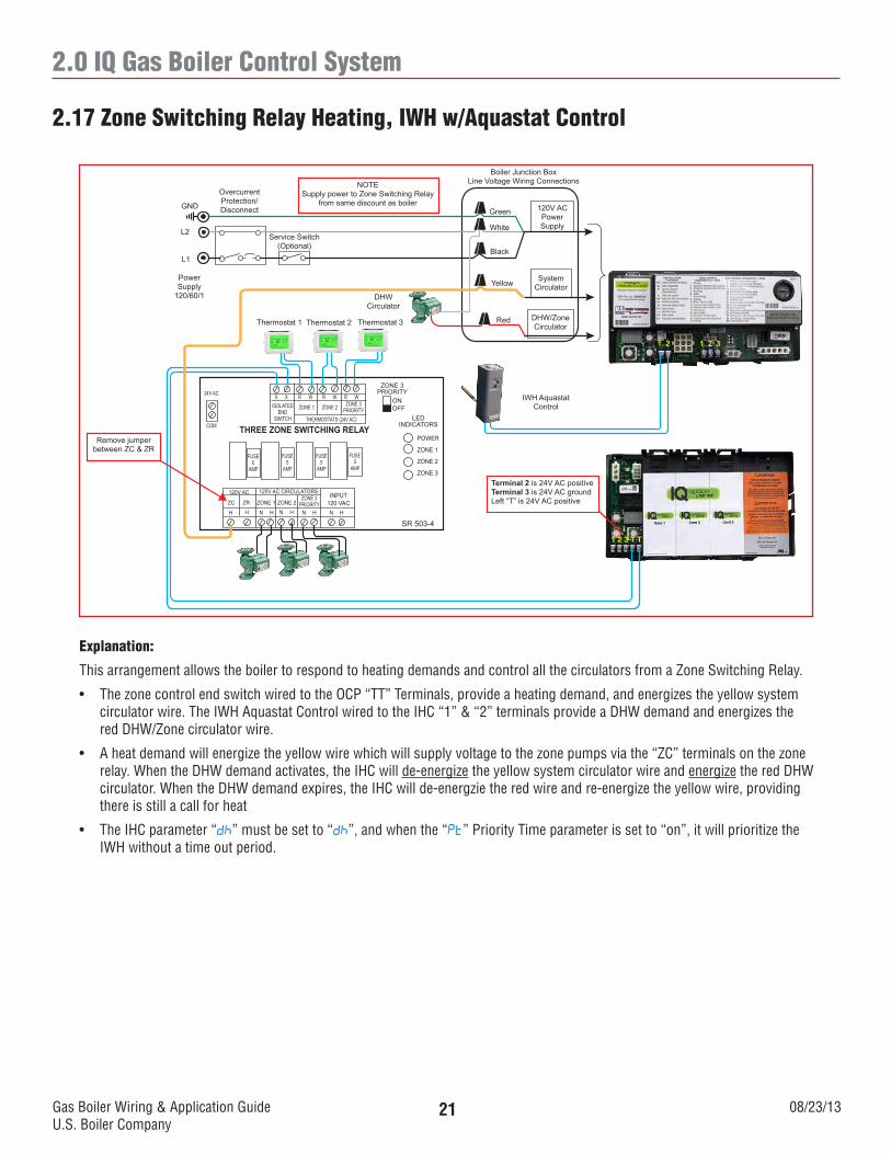
This arrangement allows the boiler to respond to heating demands and control all the circulators from a Zone Switching Relay.
• ThezonecontrolendswitchwiredtotheOCP“TT”Terminals,provideaheatingdemand,andenergizestheyellowsystemcirculator wire. The IWH Aquastat Control wired to the IHC “1” & “2” terminals provide a DHW demand and energizes the red DHW/Zone circulator wire.
• Aheatdemandwillenergizetheyellowwirewhichwillsupplyvoltagetothezonepumpsviathe“ZC”terminalsonthezonerelay. When the DHW demand activates, the IHC will de-energize the yellow system circulator wire and energize the red DHW circulator. When the DHW demand expires, the IHC will de-energzie the red wire and re-energize the yellow wire, providing there is still a call for heat
• TheIHCparameter“dh” must be set to “dh”, and when the “Pt” Priority Time parameter is set to “on”, it will prioritize the IWH without a time out period.
2.17 Zone Switching Relay Heating, IWH w/Aquastat Control
120V ACPowerSupply
SystemCirculator
DHW/ZoneCirculator
Boiler Junction BoxLine Voltage Wiring Connections
Green
White
Black
Yellow
Service Switch(Optional)
OvercurrentProtection/DisconnectGND
L2
L1
PowerSupply
120/60/1
Thermostat 1 Thermostat 2
ISOLATEDEND
SWITCH
SR 503-4
THREE ZONE SWITCHING RELAYLED
INDICATORS
POWER
ZONE 1
ZONE 2
ZONE 3
FUSE5
AMP
1 2 3 T T
1 2 1 2 3
Thermostat 3
X X R W R W R W
ZONE 1 ZONE 2 ZONE 3PRIORITY
THERMOSTATS (24V AC)
FUSE5
AMP
FUSE5
AMP
FUSE5
AMP
ZONE 3PRIORITY
ONOFF
24V AC
COM
INPUT120 VAC
120V AC CIRCULATORS120V AC
ZC ZR ZONE 1 ZONE 2ZONE 3
PRIORITYH H N H N H N H N H
Red
NOTESupply power to Zone Switching Relay
from same discount as boiler
IWH Aquastat Control
DHWCirculator
Remove jumper between ZC & ZR
Terminal 2 is 24V AC positiveTerminal 3 is 24V AC groundLeft “T” is 24V AC positive
Gas Boiler Wiring & Application GuideU.S. Boiler Company
08/23/1322
3.0 IQ Gas Boiler Control System, IQ Reset Option Card
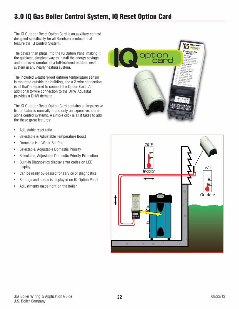
The IQ Outdoor Reset Option Card is an auxiliary control designed specifically for all Burnham products that feature the IQ Control System.
The device than plugs into the IQ Option Panel making it the quickest, simplest way to install the energy savings and improved comfort of a full-featured outdoor reset system in any nearly heating system.
The included weatherproof outdoor temperature sensor is mounted outside the building, and a 2-wire connection is all that’s required to connect the Option Card. An additional 2-wire connection to the DHW Aquastat provides a DHW demand.
The IQ Outdoor Reset Option Card contains an impressive list of features normally found only on expensive, stand-alone control systems. A simple click is all it takes to add the these great features:
• Adjustableresetratio
• Selectable&AdjustableTemperatureBoost
• DomesticHotWaterSetPoint
• Selectable,AdjustableDomesticPriority
• Selectable,AdjustableDomesticPriorityProtection
• Built-InDiagnosticsdisplayerrorcodesonLEDdisplay
• Canbeeasilyby-passedforserviceordiagnostics
• SettingsandstatusisdisplayedonIQOptionPanel
• Adjustmentsmaderightontheboiler
IQoptioncard
Gas Boiler Wiring & Application GuideU.S. Boiler Company
08/23/1323
3.0 IQ Gas Boiler Control System, IQ Reset Option Card
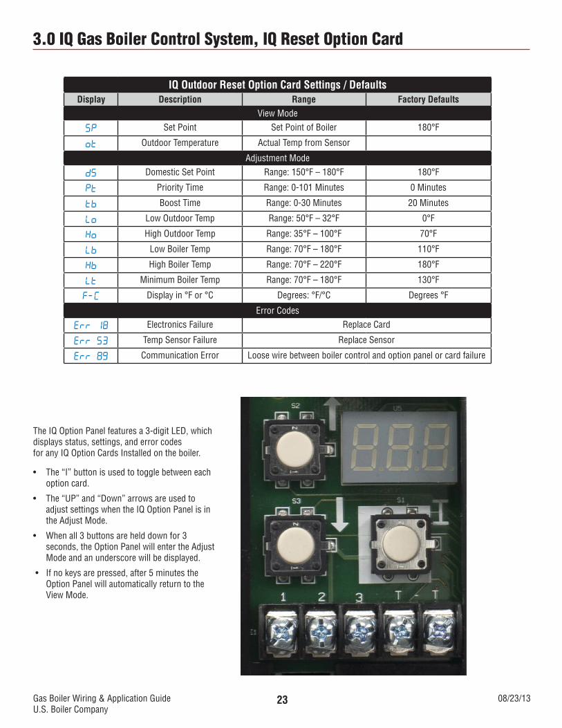
IQ Outdoor Reset Option Card Settings / DefaultsDisplay Description Range Factory Defaults
View Mode
SP Set Point Set Point of Boiler 180°F
ot Outdoor Temperature Actual Temp from Sensor
Adjustment Mode
dS Domestic Set Point Range: 150°F – 180°F 180°F
Pt Priority Time Range: 0-101 Minutes 0 Minutes
tb Boost Time Range: 0-30 Minutes 20 Minutes
Lo Low Outdoor Temp Range: 50°F – 32°F 0°F
Ho High Outdoor Temp Range: 35°F – 100°F 70°F
Lb Low Boiler Temp Range: 70°F – 180°F 110°F
Hb High Boiler Temp Range: 70°F – 220°F 180°F
Lt Minimum Boiler Temp Range: 70°F – 180°F 130°F
F-C Display in °F or °C Degrees: °F/°C Degrees °F
Error Codes
Err 18 Electronics Failure Replace Card
Err 53 Temp Sensor Failure Replace Sensor
Err 89 Communication Error Loose wire between boiler control and option panel or card failure
The IQ Option Panel features a 3-digit LED, which displays status, settings, and error codesfor any IQ Option Cards Installed on the boiler.
• The“I”buttonisusedtotogglebetweeneachoption card.
• The“UP”and“Down”arrowsareusedtoadjust settings when the IQ Option Panel is in the Adjust Mode.
• Whenall3buttonsarehelddownfor3seconds, the Option Panel will enter the Adjust Mode and an underscore will be displayed.
• Ifnokeysarepressed,after5minutestheOption Panel will automatically return to the View Mode.

Gas Boiler Wiring & Application GuideU.S. Boiler Company
08/23/1324
3.0 IQ Gas Boiler Control System, IQ Reset Option Card
Optional Control Panel – ODR Card Adjustable Mode
The optional Control Panel (OCP) has three usable slots for plug in cards. Cards can be plugged in in any order. If less than three cards are used they can be in any slot, they do not have to be in any specific order. Once the card is placed in a slot it cannot be moved to another slot without using the “Lrn” function on the OCP. If the card is moved you will receive an error code but no damage will occur to the card.
The control has three buttons used to view error codes and access the cards to view or change the parameters. If using the Outdoor Reset (ODR) card you may want to change some of the outdoor reset parameters for a more efficient operation.
If there is an IWH on the jobsite it will need to be wired to the ODR card to override the ODR feature on a call for DHW. The card will prioritize the DHW demand and you may be required or choose to change the Priority Time (Pt) the IWH will run before the heating circulators will be re-energized. A required priority time change would be if you have two circulators, one for heating and the other for DHW. The “Pt” factory default is “0” minutes, left at “0” will start both pumps wired to the boiler on a DHW demand. Starting just the DHW circulator on a DHW demand you would change the “Pt” setting from “0” to any value more than “0”. A normal range would be 20 minutes or more depending on tank size and demand.
The ODR card is located in the #2 slot on the OCP pictured above. To access the card follow the directions below;
1. Press and release the “I” button until “C2” appears on the display.
2. Press one of the Arrow buttons
3. Press and hold all three buttons at the same time until an underscore appears on the display where the bottom of the third digit would appear.
4. Press the “I” button until you see the Priority Time (Pt) parameter.
5. Press the “up arrow” button to set to desired number of minutes.
6. Press the “I” button to advance to the next parameter, this also saves the setting
7. Continue to press the “I” button until “bAc” is displayed
8. Press an arrow key to leave the parameter adjust mode.
You can stop at any parameter and make changes if needed.
Gas Boiler Wiring & Application GuideU.S. Boiler Company
08/23/1325
3.0 IQ Gas Boiler Control System, IQ Reset Option Card
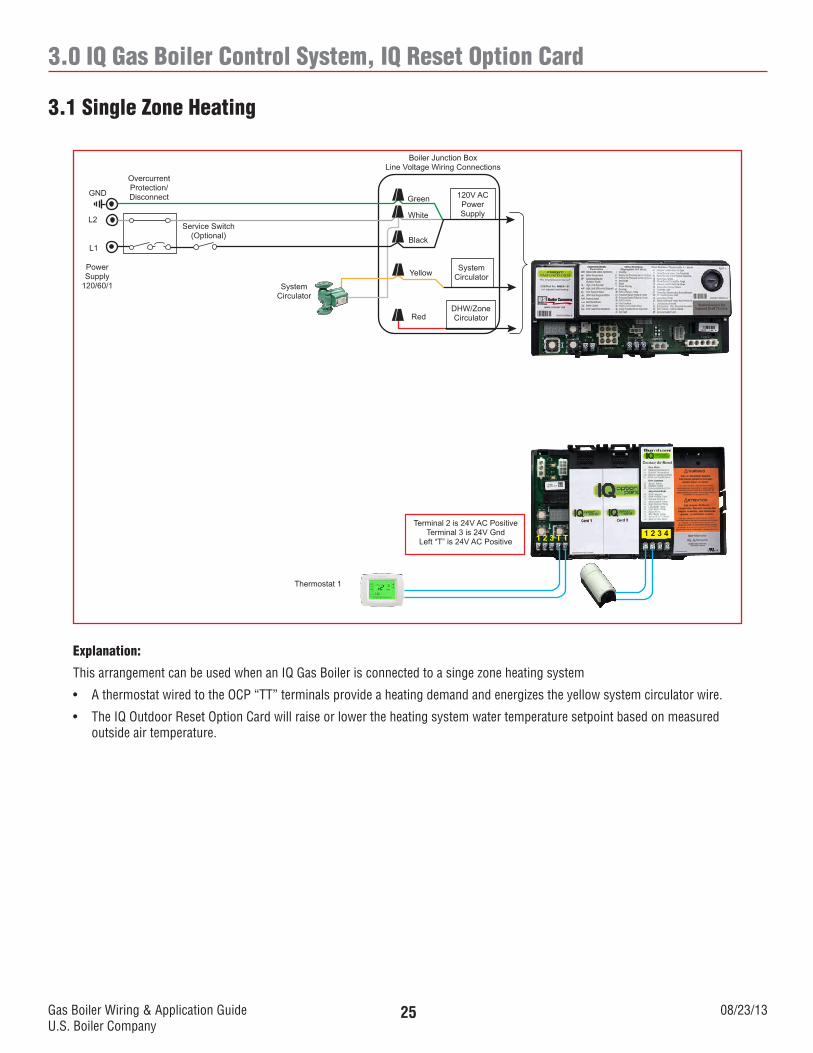
Explanation:
This arrangement can be used when an IQ Gas Boiler is connected to a singe zone heating system
• AthermostatwiredtotheOCP“TT”terminalsprovideaheatingdemandandenergizestheyellowsystemcirculatorwire.
• TheIQOutdoorResetOptionCardwillraiseorlowertheheatingsystemwatertemperaturesetpointbasedonmeasuredoutside air temperature.
3.1 Single Zone Heating
120V ACPowerSupply
SystemCirculator
DHW/ZoneCirculator
Boiler Junction BoxLine Voltage Wiring Connections
Green
White
Black
Yellow
SystemCirculator
Service Switch(Optional)
OvercurrentProtection/DisconnectGND
L2
L1
PowerSupply
120/60/1
Thermostat 1
1 2 3 T T
Red
1 2 3 4Terminal 2 is 24V AC Positive
Terminal 3 is 24V GndLeft “T” is 24V AC Positive
Gas Boiler Wiring & Application GuideU.S. Boiler Company
08/23/1326
3.0 IQ Gas Boiler Control System, IQ Reset Option Card
Explanation:
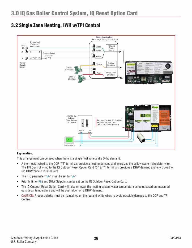
This arrangement can be used when there is a single heat zone and a DHW demand.
• AthermostatwiredtotheOCP“TT”terminalsprovideaheatingdemandandenergizestheyellowsystemcirculatorwire.The TPI Control wired to the IQ Outdoor Reset Option Card “3” & “4” terminals provides a DHW demand and energizes the red DHW/Zone circulator wire.
• TheIHCparameter“dh” must be set to “dh”
• Prioritytime(Pt) and DHW Setpoint can be set on the IQ Outdoor Reset Option Card.
• TheIQOutdoorResetOptionCardwillraiseorlowertheheatingsystemwatertemperaturesetpointbasedonmeasuredoutside air temperature and will be overridden on a DHW demand.
• CAUTION: Proper polarity must be maintained on the red and white wires to avoid possible damage to the OCP and TPI Control.
3.2 Single Zone Heating, IWH w/TPI Control
120V ACPowerSupply
SystemCirculator
DHW/ZoneCirculator
Boiler Junction BoxLine Voltage Wiring Connections
Green
White
Black
Yellow
Zone 1Circulator
Service Switch(Optional)
OvercurrentProtection/DisconnectGND
L2
L1
PowerSupply
120/60/1
Thermostat 1
1 2 3 T T
Red
1 2 3 4
Terminal 2 is 24V AC PositiveTerminal 3 is 24V GndLeft “T” is 24V AC Positive
Alliance SLIndirect
Water HeaterTPI Control
Zone 2Circulator
24Vpump/TT
Gas Boiler Wiring & Application GuideU.S. Boiler Company
08/23/1327
3.0 IQ Gas Boiler Control System, IQ Reset Option Card
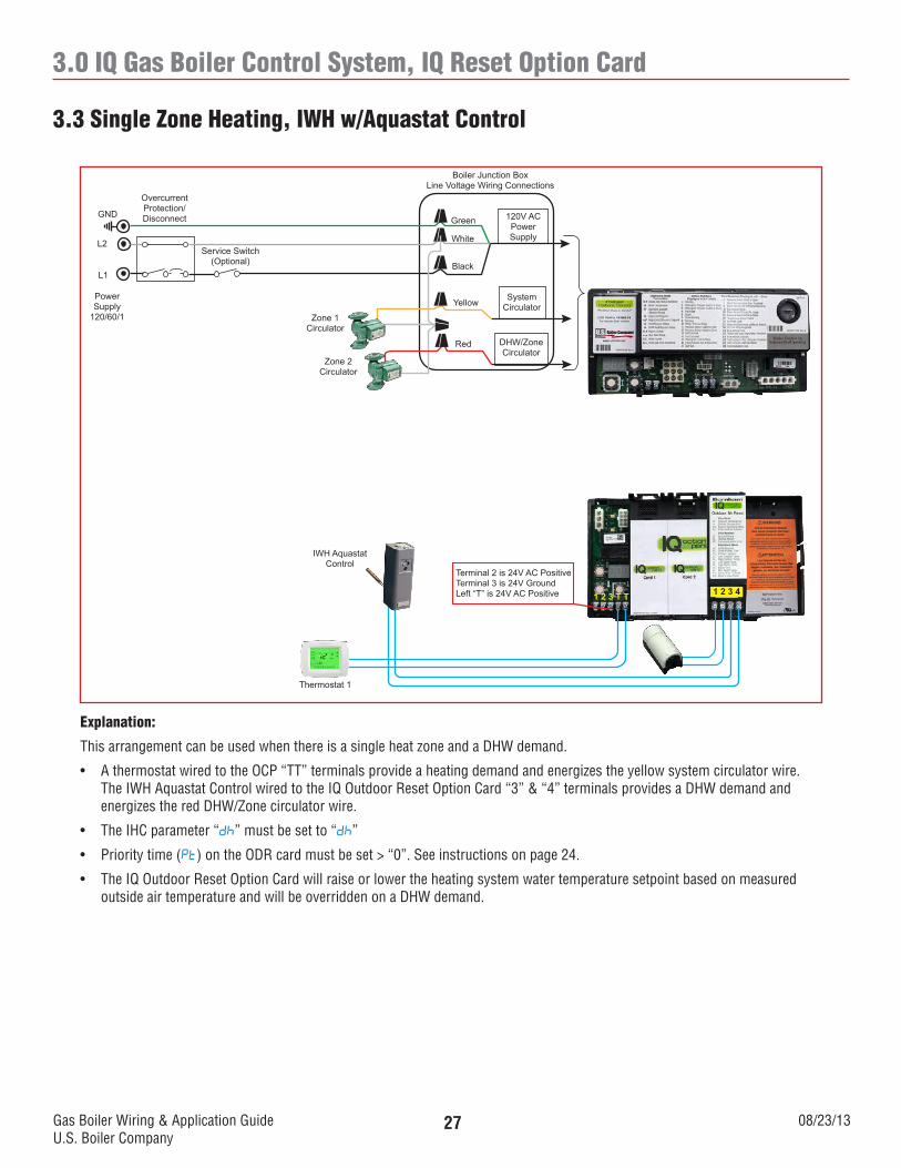
Explanation:
This arrangement can be used when there is a single heat zone and a DHW demand.
• AthermostatwiredtotheOCP“TT”terminalsprovideaheatingdemandandenergizestheyellowsystemcirculatorwire.The IWH Aquastat Control wired to the IQ Outdoor Reset Option Card “3” & “4” terminals provides a DHW demand and energizes the red DHW/Zone circulator wire.
• TheIHCparameter“dh” must be set to “dh”
• Prioritytime(Pt) on the ODR card must be set > “0”. See instructions on page 24.
• TheIQOutdoorResetOptionCardwillraiseorlowertheheatingsystemwatertemperaturesetpointbasedonmeasuredoutside air temperature and will be overridden on a DHW demand.
3.3 Single Zone Heating, IWH w/Aquastat Control
120V ACPowerSupply
SystemCirculator
DHW/ZoneCirculator
Boiler Junction BoxLine Voltage Wiring Connections
Green
White
Black
Yellow
Zone 1Circulator
Service Switch(Optional)
OvercurrentProtection/DisconnectGND
L2
L1
PowerSupply
120/60/1
Thermostat 1
1 2 3 T T
Red
1 2 3 4
Terminal 2 is 24V AC PositiveTerminal 3 is 24V GroundLeft “T” is 24V AC Positive
Zone 2Circulator
IWH Aquastat Control
Gas Boiler Wiring & Application GuideU.S. Boiler Company
08/23/1328
3.0 IQ Gas Boiler Control System, IQ Reset Option Card
Explanation:
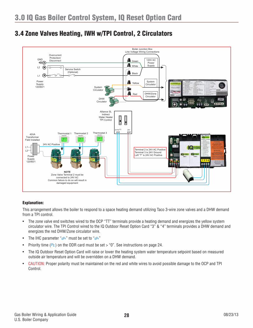
This arrangement allows the boiler to respond to a space heating demand utilizing Taco 3-wire zone valves and a DHW demand from a TPI control.
• ThezonevalveendswitcheswiredtotheOCP“TT”terminalsprovideaheatingdemandandenergizestheyellowsystemcirculator wire. The TPI Control wired to the IQ Outdoor Reset Option Card “3” & “4” terminals provides a DHW demand and energizes the red DHW/Zone circulator wire.
• TheIHCparameter“dh” must be set to “dh”
• Prioritytime(Pt) on the ODR card must be set > “0”. See instructions on page 24.
• TheIQOutdoorResetOptionCardwillraiseorlowertheheatingsystemwatertemperaturesetpointbasedonmeasuredoutside air temperature and will be overridden on a DHW demand.
• CAUTION: Proper polarity must be maintained on the red and white wires to avoid possible damage to the OCP and TPI Control.
3.4 Zone Valves Heating, IWH w/TPI Control, 2 Circulators
120V ACPowerSupply
SystemCirculator
DHW/ZoneCirculator
Boiler Junction BoxLine Voltage Wiring Connections
Green
White
Black
Yellow
SystemCirculator
Service Switch(Optional)
OvercurrentProtection/DisconnectGND
L2
L1
PowerSupply
120/60/1
1 2 3 T T
Red
1 2 3 4
Terminal 2 is 24V AC PositiveTerminal 3 is 24V GroundLeft “T” is 24V AC Positive
DHWCirculator
Alliance SLIndirect
Water HeaterTPI Control
Thermostat 3Thermostat 2Thermostat 1
24V AC Positive
40VA Transformer
Field Installed
Power Supply
120/60/1
L1L2
NOTEZone Valve Terminal 2 must be
connected to 24V ACCommon failure to do so will result in
damaged equipment
24Vpump/TT
Gas Boiler Wiring & Application GuideU.S. Boiler Company
08/23/1329
3.0 IQ Gas Boiler Control System, IQ Reset Option Card
Explanation:
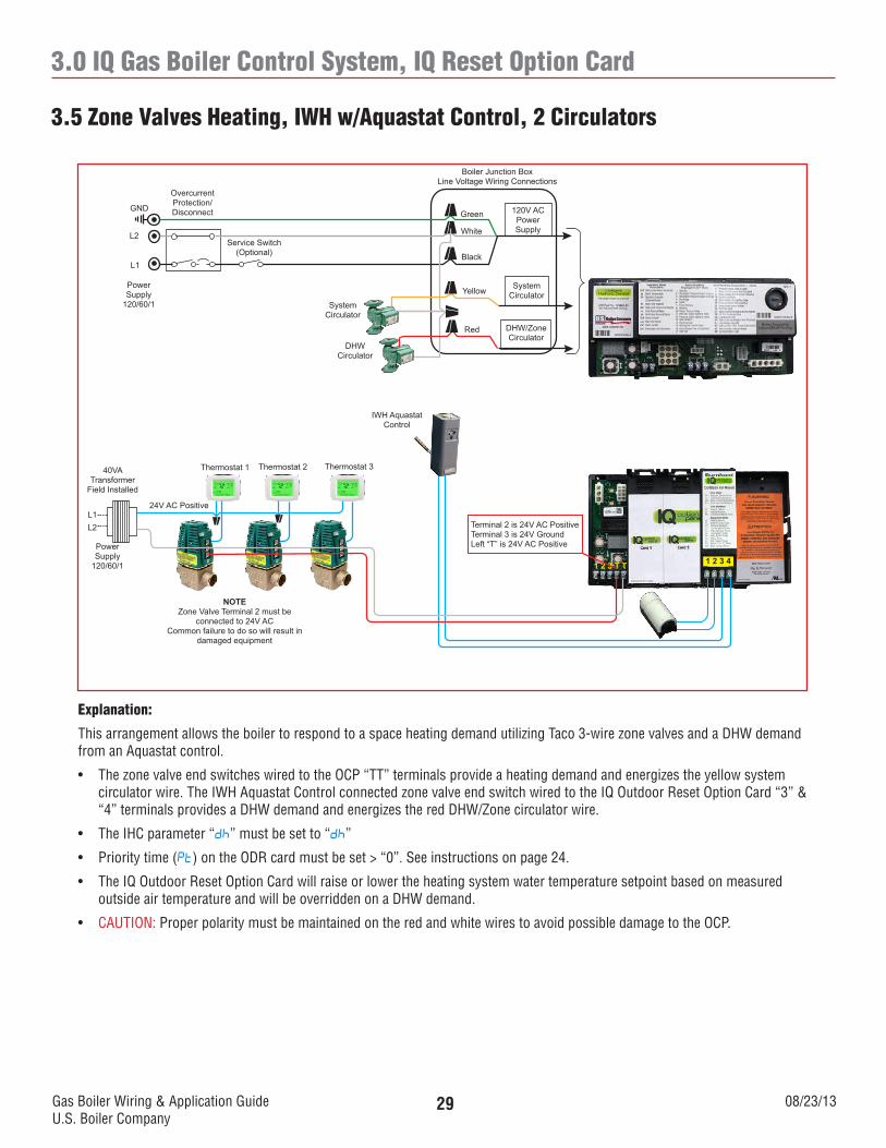
This arrangement allows the boiler to respond to a space heating demand utilizing Taco 3-wire zone valves and a DHW demand from an Aquastat control.
• ThezonevalveendswitcheswiredtotheOCP“TT”terminalsprovideaheatingdemandandenergizestheyellowsystemcirculator wire. The IWH Aquastat Control connected zone valve end switch wired to the IQ Outdoor Reset Option Card “3” & “4” terminals provides a DHW demand and energizes the red DHW/Zone circulator wire.
• TheIHCparameter“dh” must be set to “dh”
• Prioritytime(Pt) on the ODR card must be set > “0”. See instructions on page 24.
• TheIQOutdoorResetOptionCardwillraiseorlowertheheatingsystemwatertemperaturesetpointbasedonmeasuredoutside air temperature and will be overridden on a DHW demand.
• CAUTION: Proper polarity must be maintained on the red and white wires to avoid possible damage to the OCP.
3.5 Zone Valves Heating, IWH w/Aquastat Control, 2 Circulators
120V ACPowerSupply
SystemCirculator
DHW/ZoneCirculator
Boiler Junction BoxLine Voltage Wiring Connections
Green
White
Black
Yellow
SystemCirculator
Service Switch(Optional)
OvercurrentProtection/DisconnectGND
L2
L1
PowerSupply
120/60/1
1 2 3 T T
Red
1 2 3 4
Terminal 2 is 24V AC PositiveTerminal 3 is 24V GroundLeft “T” is 24V AC Positive
DHWCirculator
Thermostat 3Thermostat 2Thermostat 1
24V AC Positive
40VA Transformer
Field Installed
Power Supply
120/60/1
L1L2
NOTEZone Valve Terminal 2 must be
connected to 24V ACCommon failure to do so will result in
damaged equipment
IWH Aquastat Control
Gas Boiler Wiring & Application GuideU.S. Boiler Company
08/23/1330
3.0 IQ Gas Boiler Control System, IQ Reset Option Card
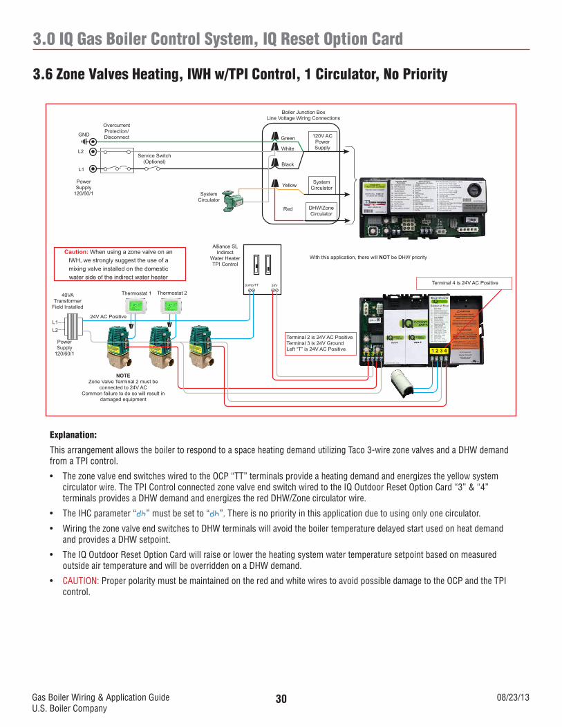
3.6 Zone Valves Heating, IWH w/TPI Control, 1 Circulator, No Priority
120V ACPowerSupply
SystemCirculator
DHW/ZoneCirculator
Boiler Junction BoxLine Voltage Wiring Connections
Green
White
Black
Yellow
SystemCirculator
Service Switch(Optional)
OvercurrentProtection/DisconnectGND
L2
L1
PowerSupply
120/60/1
1 2 3 T T
Red
1 2 3 4
Terminal 2 is 24V AC PositiveTerminal 3 is 24V GroundLeft “T” is 24V AC Positive
Alliance SLIndirect
Water HeaterTPI Control
Thermostat 2Thermostat 1
24V AC Positive
40VA Transformer
Field Installed
Power Supply
120/60/1
L1L2
NOTEZone Valve Terminal 2 must be
connected to 24V ACCommon failure to do so will result in
damaged equipment
With this application, there will NOT be DHW priorityCaution: When using a zone valve on an
IWH, we strongly suggest the use of a mixing valve installed on the domestic water side of the indirect water heater
Terminal 4 is 24V AC Positive24Vpump/TT
Explanation:
This arrangement allows the boiler to respond to a space heating demand utilizing Taco 3-wire zone valves and a DHW demand from a TPI control.
• ThezonevalveendswitcheswiredtotheOCP“TT”terminalsprovideaheatingdemandandenergizestheyellowsystemcirculator wire. The TPI Control connected zone valve end switch wired to the IQ Outdoor Reset Option Card “3” & “4” terminals provides a DHW demand and energizes the red DHW/Zone circulator wire.
• TheIHCparameter“dh” must be set to “dh”. There is no priority in this application due to using only one circulator.
• WiringthezonevalveendswitchestoDHWterminalswillavoidtheboilertemperaturedelayedstartusedonheatdemandand provides a DHW setpoint.
• TheIQOutdoorResetOptionCardwillraiseorlowertheheatingsystemwatertemperaturesetpointbasedonmeasuredoutside air temperature and will be overridden on a DHW demand.
• CAUTION: Proper polarity must be maintained on the red and white wires to avoid possible damage to the OCP and the TPI control.
Gas Boiler Wiring & Application GuideU.S. Boiler Company
08/23/1331
3.0 IQ Gas Boiler Control System, IQ Reset Option Card
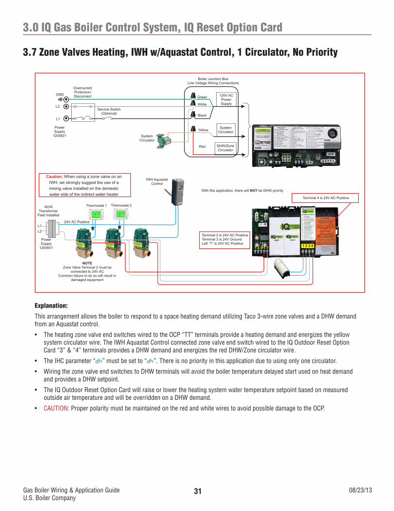
3.7 Zone Valves Heating, IWH w/Aquastat Control, 1 Circulator, No Priority
120V ACPowerSupply
SystemCirculator
DHW/ZoneCirculator
Boiler Junction BoxLine Voltage Wiring Connections
Green
White
Black
Yellow
SystemCirculator
Service Switch(Optional)
OvercurrentProtection/DisconnectGND
L2
L1
PowerSupply
120/60/1
1 2 3 T T
Red
1 2 3 4
Terminal 2 is 24V AC PositiveTerminal 3 is 24V GroundLeft “T” is 24V AC Positive
Thermostat 2Thermostat 1
24V AC Positive
40VA Transformer
Field Installed
Power Supply
120/60/1
L1L2
NOTEZone Valve Terminal 2 must be
connected to 24V ACCommon failure to do so will result in
damaged equipment
With this application, there will NOT be DHW priority
Caution: When using a zone valve on an IWH, we strongly suggest the use of a mixing valve installed on the domestic water side of the indirect water heater
Terminal 4 is 24V AC Positive
IWH Aquastat Control
Explanation:
This arrangement allows the boiler to respond to a space heating demand utilizing Taco 3-wire zone valves and a DHW demand from an Aquastat control.
• TheheatingzonevalveendswitcheswiredtotheOCP“TT”terminalsprovideaheatingdemandandenergizestheyellowsystem circulator wire. The IWH Aquastat Control connected zone valve end switch wired to the IQ Outdoor Reset Option Card “3” & “4” terminals provides a DHW demand and energizes the red DHW/Zone circulator wire.
• TheIHCparameter“dh” must be set to “dh”. There is no priority in this application due to using only one circulator.
• WiringthezonevalveendswitchestoDHWterminalswillavoidtheboilertemperaturedelayedstartusedonheatdemandand provides a DHW setpoint.
• TheIQOutdoorResetOptionCardwillraiseorlowertheheatingsystemwatertemperaturesetpointbasedonmeasuredoutside air temperature and will be overridden on a DHW demand.
• CAUTION: Proper polarity must be maintained on the red and white wires to avoid possible damage to the OCP.
Gas Boiler Wiring & Application GuideU.S. Boiler Company
08/23/1332
3.0 IQ Gas Boiler Control System, IQ Reset Option Card
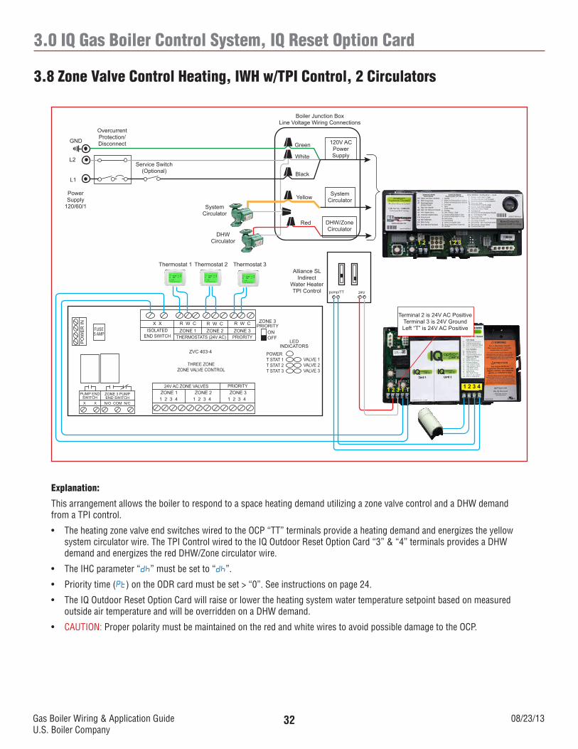
3.8 Zone Valve Control Heating, IWH w/TPI Control, 2 Circulators
1 2 3 T T 1 2 3 4
Thermostat 1 Thermostat 2
X X R W C R W C R W CZONE 1 ZONE 2 ZONE 3
THERMOSTATS (24V AC) PRIORITYISOLATED
END SWITCH
ZVC 403-4
THREE ZONEZONE VALVE CONTROL
ZONE 1 ZONE 2 ZONE 3PRIORITY24V AC ZONE VALVES
1 2 3 4 1 2 3 41 2 3 4
ZONE 3PRIORITY
ONOFF
LEDINDICATORS
POWERT STAT 1T STAT 2T STAT 3
VALVE 1VALVE 2VALVE 3
FUSE5 AMP
PO
WE
R IN
ZONE 3 PUMPEND SWITCH
PUMP END SWITCH
N/O COM N/CX X
1 2 1 2 3
120V ACPowerSupply
SystemCirculator
DHW/ZoneCirculator
Boiler Junction BoxLine Voltage Wiring Connections
Green
White
Black
Yellow
SystemCirculator
Service Switch(Optional)
OvercurrentProtection/DisconnectGND
L2
L1
PowerSupply
120/60/1
Red
DHWCirculator
Alliance SLIndirect
Water HeaterTPI Control
Thermostat 3
Terminal 2 is 24V AC PositiveTerminal 3 is 24V GroundLeft “T” is 24V AC Positive
24Vpump/TT
Explanation:
This arrangement allows the boiler to respond to a space heating demand utilizing a zone valve control and a DHW demand from a TPI control.
• TheheatingzonevalveendswitcheswiredtotheOCP“TT”terminalsprovideaheatingdemandandenergizestheyellowsystem circulator wire. The TPI Control wired to the IQ Outdoor Reset Option Card “3” & “4” terminals provides a DHW demand and energizes the red DHW/Zone circulator wire.
• TheIHCparameter“dh” must be set to “dh”.
• Prioritytime(Pt) on the ODR card must be set > “0”. See instructions on page 24.
• TheIQOutdoorResetOptionCardwillraiseorlowertheheatingsystemwatertemperaturesetpointbasedonmeasuredoutside air temperature and will be overridden on a DHW demand.
• CAUTION: Proper polarity must be maintained on the red and white wires to avoid possible damage to the OCP.
Gas Boiler Wiring & Application GuideU.S. Boiler Company
08/23/1333
3.0 IQ Gas Boiler Control System, IQ Reset Option Card
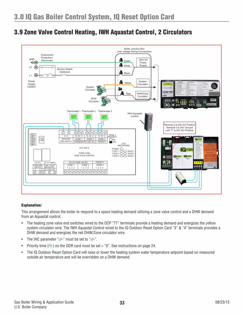
3.9 Zone Valve Control Heating, IWH Aquastat Control, 2 Circulators
1 2 3 T T 1 2 3 4
Thermostat 1 Thermostat 2
X X R W C R W C R W CZONE 1 ZONE 2 ZONE 3
THERMOSTATS (24V AC) PRIORITYISOLATED
END SWITCH
ZVC 403-4
THREE ZONEZONE VALVE CONTROL
ZONE 1 ZONE 2 ZONE 3PRIORITY24V AC ZONE VALVES
1 2 3 4 1 2 3 41 2 3 4
ZONE 3PRIORITY
ONOFF
LEDINDICATORS
POWERT STAT 1T STAT 2T STAT 3
VALVE 1VALVE 2VALVE 3
FUSE5 AMP
PO
WE
R IN
ZONE 3 PUMPEND SWITCH
PUMP END SWITCH
N/O COM N/CX X
1 2 1 2 3
120V ACPowerSupply
SystemCirculator
DHW/ZoneCirculator
Boiler Junction BoxLine Voltage Wiring Connections
Green
White
Black
Yellow
SystemCirculator
Service Switch(Optional)
OvercurrentProtection/DisconnectGND
L2
L1
PowerSupply
120/60/1
Red
DHWCirculator
Thermostat 3
Terminal 2 is 24V AC PositiveTerminal 3 is 24V GroundLeft “T” is 24V AC Positive
IWH Aquastat Control
Explanation:
This arrangement allows the boiler to respond to a space heating demand utilizing a zone valve control and a DHW demand from an Aquastat control.
• TheheatingzonevalveendswitcheswiredtotheOCP“TT”terminalsprovideaheatingdemandandenergizestheyellowsystem circulator wire. The IWH Aquastat Control wired to the IQ Outdoor Reset Option Card “3” & “4” terminals provides a DHW demand and energizes the red DHW/Zone circulator wire.
• TheIHCparameter“dh” must be set to “dh”.
• Prioritytime(Pt) on the ODR card must be set > “0”. See instructions on page 24.
• TheIQOutdoorResetOptionCardwillraiseorlowertheheatingsystemwatertemperaturesetpointbasedonmeasuredoutside air temperature and will be overridden on a DHW demand.
Gas Boiler Wiring & Application GuideU.S. Boiler Company
08/23/1334
3.0 IQ Gas Boiler Control System, IQ Reset Option Card
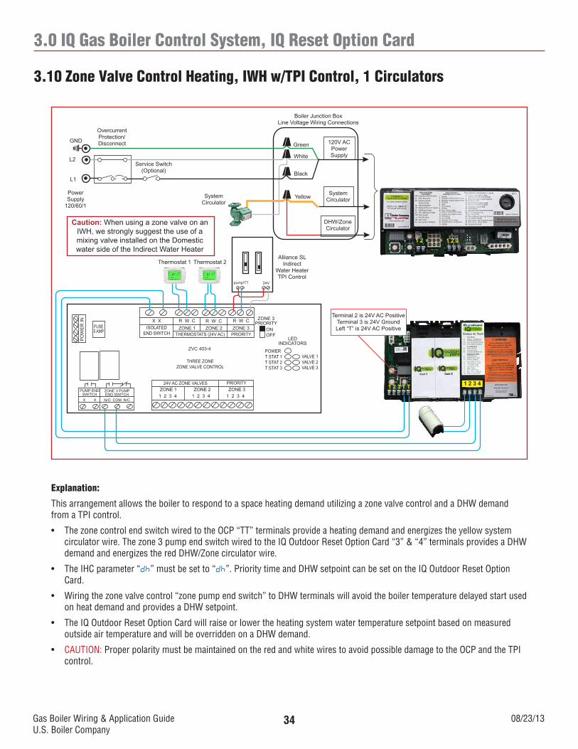
3.10 Zone Valve Control Heating, IWH w/TPI Control, 1 Circulators
120V ACPowerSupply
SystemCirculator
DHW/ZoneCirculator
Boiler Junction BoxLine Voltage Wiring Connections
Green
White
Black
YellowSystemCirculator
Service Switch(Optional)
OvercurrentProtection/DisconnectGND
L2
L1
PowerSupply
120/60/1
Caution: When using a zone valve on an IWH, we strongly suggest the use of a mixing valve installed on the Domestic water side of the Indirect Water Heater
Thermostat 1 Thermostat 2
X X R W C R W C R W CZONE 1 ZONE 2 ZONE 3
THERMOSTATS (24V AC) PRIORITYISOLATED
END SWITCH
ZVC 403-4
THREE ZONEZONE VALVE CONTROL
ZONE 1 ZONE 2 ZONE 3PRIORITY24V AC ZONE VALVES
1 2 3 4 1 2 3 41 2 3 4
ZONE 3PRIORITY
ONOFF
LEDINDICATORS
POWERT STAT 1T STAT 2T STAT 3
VALVE 1VALVE 2VALVE 3
FUSE5 AMP
PO
WE
R IN
ZONE 3 PUMPEND SWITCH
PUMP END SWITCH
N/O COM N/CX X
1 2 1 2 3
Alliance SLIndirect
Water HeaterTPI Control
1 2 3 T T 1 2 3 4
Terminal 2 is 24V AC PositiveTerminal 3 is 24V GroundLeft “T” is 24V AC Positive
24Vpump/TT
Explanation:
This arrangement allows the boiler to respond to a space heating demand utilizing a zone valve control and a DHW demand from a TPI control.
• ThezonecontrolendswitchwiredtotheOCP“TT”terminalsprovideaheatingdemandandenergizestheyellowsystemcirculator wire. The zone 3 pump end switch wired to the IQ Outdoor Reset Option Card “3” & “4” terminals provides a DHW demand and energizes the red DHW/Zone circulator wire.
• TheIHCparameter“dh” must be set to “dh”. Priority time and DHW setpoint can be set on the IQ Outdoor Reset Option Card.
• Wiringthezonevalvecontrol“zonepumpendswitch”toDHWterminalswillavoidtheboilertemperaturedelayedstartusedon heat demand and provides a DHW setpoint.
• TheIQOutdoorResetOptionCardwillraiseorlowertheheatingsystemwatertemperaturesetpointbasedonmeasuredoutside air temperature and will be overridden on a DHW demand.
• CAUTION: Proper polarity must be maintained on the red and white wires to avoid possible damage to the OCP and the TPI control.
Gas Boiler Wiring & Application GuideU.S. Boiler Company
08/23/1335
3.0 IQ Gas Boiler Control System, IQ Reset Option Card
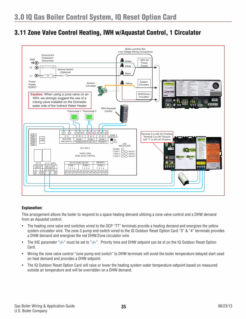
3.11 Zone Valve Control Heating, IWH w/Aquastat Control, 1 Circulator
120V ACPowerSupply
SystemCirculator
DHW/ZoneCirculator
Boiler Junction BoxLine Voltage Wiring Connections
Green
White
Black
YellowSystemCirculator
Service Switch(Optional)
OvercurrentProtection/DisconnectGND
L2
L1
PowerSupply
120/60/1
Caution: When using a zone valve on an IWH, we strongly suggest the use of a mixing valve installed on the Domestic water side of the Indirect Water Heater
Thermostat 1 Thermostat 2
X X R W C R W C R W CZONE 1 ZONE 2 ZONE 3
THERMOSTATS (24V AC) PRIORITYISOLATED
END SWITCH
ZVC 403-4
THREE ZONEZONE VALVE CONTROL
ZONE 1 ZONE 2 ZONE 3PRIORITY24V AC ZONE VALVES
1 2 3 4 1 2 3 41 2 3 4
ZONE 3PRIORITY
ONOFF
LEDINDICATORS
POWERT STAT 1T STAT 2T STAT 3
VALVE 1VALVE 2VALVE 3
FUSE5 AMP
PO
WE
R IN
ZONE 3 PUMPEND SWITCH
PUMP END SWITCH
N/O COM N/CX X
1 2 1 2 3
1 2 3 T T 1 2 3 4
Terminal 2 is 24V AC PositiveTerminal 3 is 24V GroundLeft “T” is 24V AC Positive
IWH AquastatControl
Explanation:
This arrangement allows the boiler to respond to a space heating demand utilizing a zone valve control and a DHW demand from an Aquastat control.
• TheheatingzonevalveendswitcheswiredtotheOCP“TT”terminalsprovideaheatingdemandandenergizestheyellowsystem circulator wire. The zone 3 pump end switch wired to the IQ Outdoor Reset Option Card “3” & “4” terminals provides a DHW demand and energizes the red DHW/Zone circulator wire.
• TheIHCparameter“dh” must be set to “dh”. Priority time and DHW setpoint can be st on the IQ Outdoor Reset Option Card.
• Wiringthezonevalvecontrol“zonepumpendswitch”toDHWterminalswillavoidtheboilertemperaturedelayedstartusedon heat demand and provides a DHW setpoint.
• TheIQOutdoorResetOptionCardwillraiseorlowertheheatingsystemwatertemperaturesetpointbasedonmeasuredoutside air temperature and will be overridden on a DHW demand.
Gas Boiler Wiring & Application GuideU.S. Boiler Company
08/23/1336
3.0 IQ Gas Boiler Control System, IQ Reset Option Card
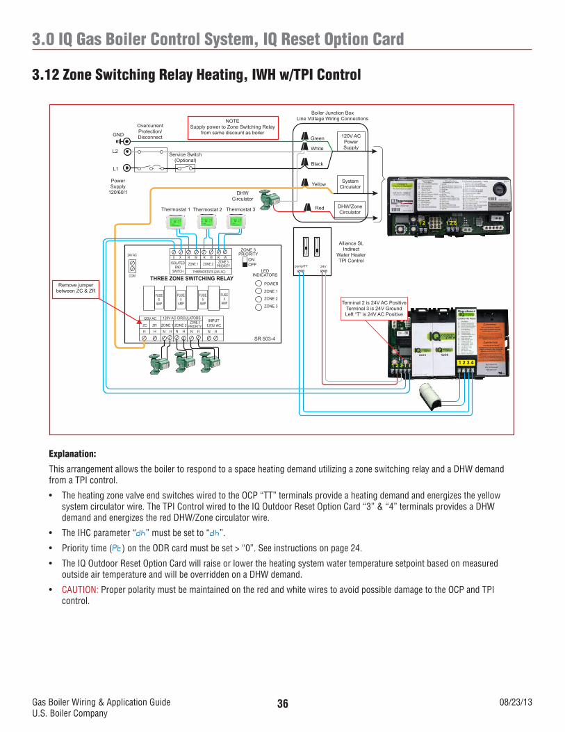
3.12 Zone Switching Relay Heating, IWH w/TPI Control
120V ACPowerSupply
SystemCirculator
DHW/ZoneCirculator
Boiler Junction BoxLine Voltage Wiring Connections
Green
White
Black
Yellow
Service Switch(Optional)
OvercurrentProtection/DisconnectGND
L2
L1
PowerSupply
120/60/1
Thermostat 1 Thermostat 2
ISOLATEDEND
SWITCH
SR 503-4
THREE ZONE SWITCHING RELAYLED
INDICATORS
POWER
ZONE 1
ZONE 2
ZONE 3
FUSE5
AMP
1 2 1 2 3
Thermostat 3
X X R W R W R W
ZONE 1 ZONE 2 ZONE 3PRIORITY
THERMOSTATS (24V AC)
FUSE5
AMP
FUSE5
AMP
FUSE5
AMP
ZONE 3PRIORITY
ONOFF
24V AC
COM
INPUT120V AC
120V AC CIRCULATORS120V AC
ZC ZR ZONE 1 ZONE 2ZONE 3
PRIORITYH H N H N H N H N H
Red
NOTESupply power to Zone Switching Relay
from same discount as boiler
Alliance SLIndirect
Water HeaterTPI Control
DHWCirculator
Remove jumper between ZC & ZR
1 2 3 T T 1 2 3 4
Terminal 2 is 24V AC PositiveTerminal 3 is 24V GroundLeft “T” is 24V AC Positive
24Vpump/TT
Explanation:
This arrangement allows the boiler to respond to a space heating demand utilizing a zone switching relay and a DHW demand from a TPI control.
• TheheatingzonevalveendswitcheswiredtotheOCP“TT”terminalsprovideaheatingdemandandenergizestheyellowsystem circulator wire. The TPI Control wired to the IQ Outdoor Reset Option Card “3” & “4” terminals provides a DHW demand and energizes the red DHW/Zone circulator wire.
• TheIHCparameter“dh” must be set to “dh”.
• Prioritytime(Pt) on the ODR card must be set > “0”. See instructions on page 24.
• TheIQOutdoorResetOptionCardwillraiseorlowertheheatingsystemwatertemperaturesetpointbasedonmeasuredoutside air temperature and will be overridden on a DHW demand.
• CAUTION: Proper polarity must be maintained on the red and white wires to avoid possible damage to the OCP and TPI control.
Gas Boiler Wiring & Application GuideU.S. Boiler Company
08/23/1337
3.0 IQ Gas Boiler Control System, IQ Reset Option Card
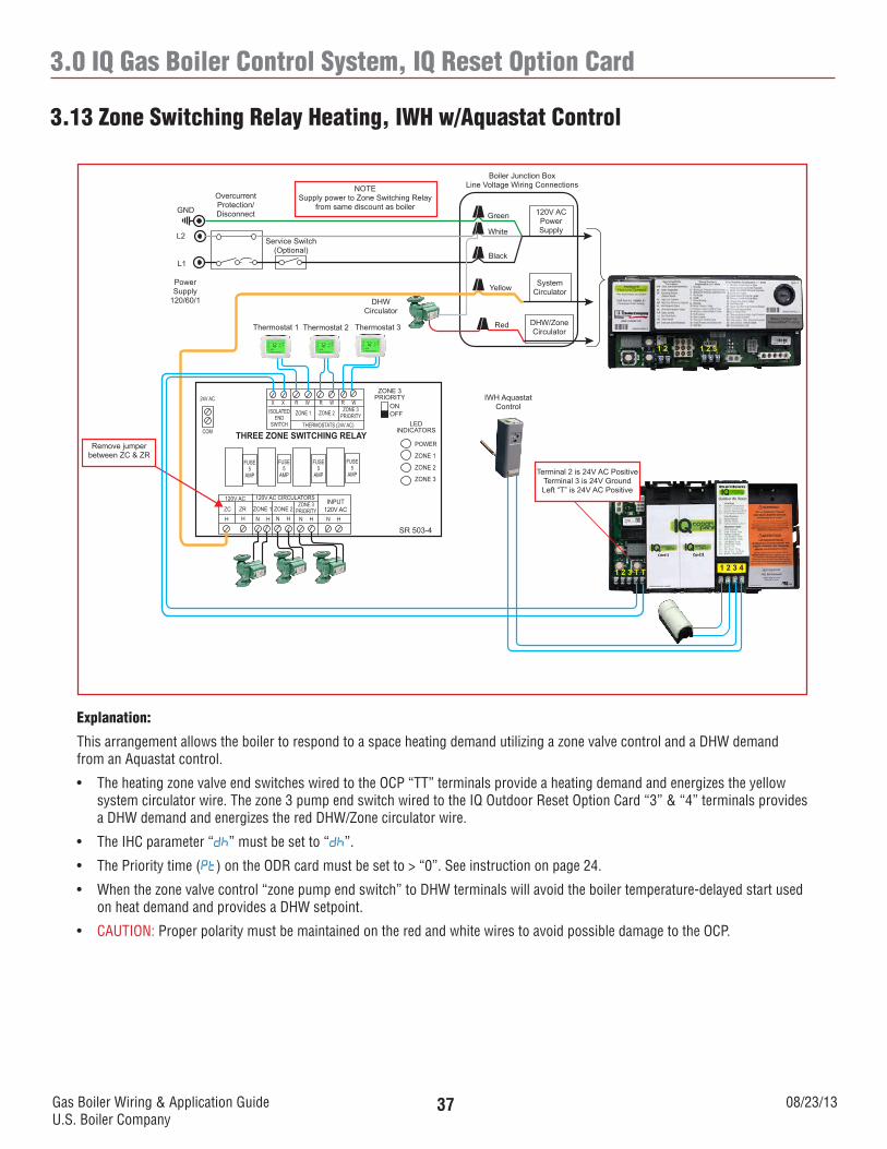
3.13 Zone Switching Relay Heating, IWH w/Aquastat Control
120V ACPowerSupply
SystemCirculator
DHW/ZoneCirculator
Boiler Junction BoxLine Voltage Wiring Connections
Green
White
Black
Yellow
Service Switch(Optional)
OvercurrentProtection/DisconnectGND
L2
L1
PowerSupply
120/60/1
Thermostat 1 Thermostat 2
ISOLATEDEND
SWITCH
SR 503-4
THREE ZONE SWITCHING RELAYLED
INDICATORS
POWER
ZONE 1
ZONE 2
ZONE 3
FUSE5
AMP
1 2 1 2 3
Thermostat 3
X X R W R W R W
ZONE 1 ZONE 2 ZONE 3PRIORITY
THERMOSTATS (24V AC)
FUSE5
AMP
FUSE5
AMP
FUSE5
AMP
ZONE 3PRIORITY
ONOFF
24V AC
COM
INPUT120V AC
120V AC CIRCULATORS120V AC
ZC ZR ZONE 1 ZONE 2ZONE 3
PRIORITYH H N H N H N H N H
Red
NOTESupply power to Zone Switching Relay
from same discount as boiler
DHWCirculator
Remove jumper between ZC & ZR
1 2 3 T T 1 2 3 4
Terminal 2 is 24V AC PositiveTerminal 3 is 24V GroundLeft “T” is 24V AC Positive
IWH AquastatControl
Explanation:
This arrangement allows the boiler to respond to a space heating demand utilizing a zone valve control and a DHW demand from an Aquastat control.
• TheheatingzonevalveendswitcheswiredtotheOCP“TT”terminalsprovideaheatingdemandandenergizestheyellowsystem circulator wire. The zone 3 pump end switch wired to the IQ Outdoor Reset Option Card “3” & “4” terminals provides a DHW demand and energizes the red DHW/Zone circulator wire.
• TheIHCparameter“dh” must be set to “dh”.
• ThePrioritytime(Pt) on the ODR card must be set to > “0”. See instruction on page 24.
• Whenthezonevalvecontrol“zonepumpendswitch”toDHWterminalswillavoidtheboilertemperature-delayedstartusedon heat demand and provides a DHW setpoint.
• CAUTION: Proper polarity must be maintained on the red and white wires to avoid possible damage to the OCP.
Gas Boiler Wiring & Application GuideU.S. Boiler Company
08/23/1338
4.0 Intelligent Hydronic Control (IHC)
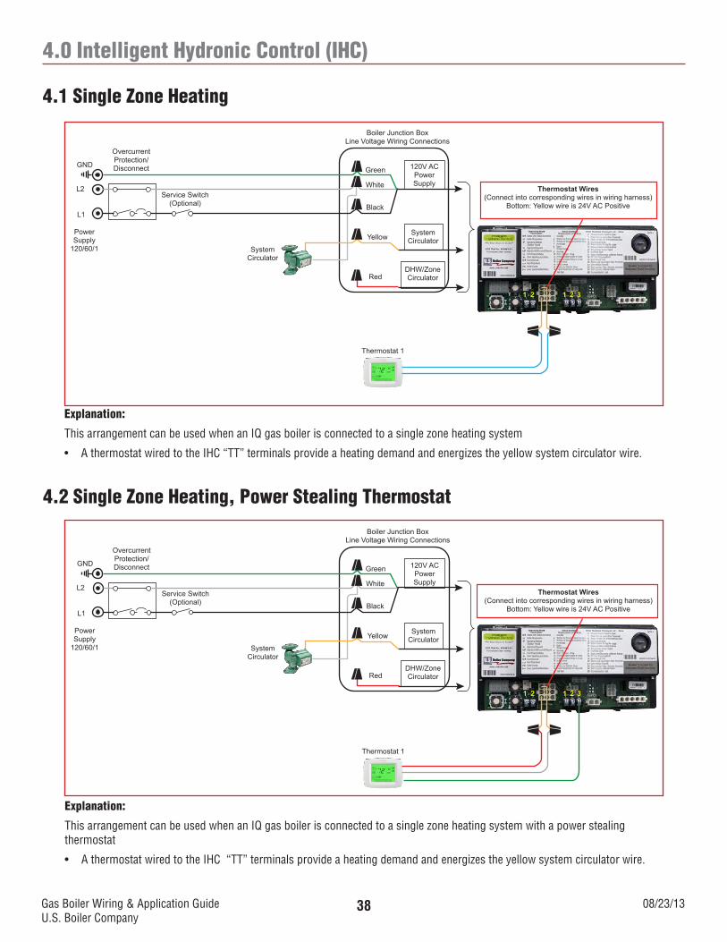
4.1 Single Zone Heating
120V ACPowerSupply
SystemCirculator
DHW/ZoneCirculator
Boiler Junction BoxLine Voltage Wiring Connections
Green
White
Black
Yellow
SystemCirculator
Service Switch(Optional)
OvercurrentProtection/DisconnectGND
L2
L1
PowerSupply
120/60/1
Thermostat 1
1 2 1 2 3
Red
Thermostat Wires(Connect into corresponding wires in wiring harness)
Bottom: Yellow wire is 24V AC Positive
Explanation:
This arrangement can be used when an IQ gas boiler is connected to a single zone heating system
• AthermostatwiredtotheIHC“TT”terminalsprovideaheatingdemandandenergizestheyellowsystemcirculatorwire.
4.2 Single Zone Heating, Power Stealing Thermostat
120V ACPowerSupply
SystemCirculator
DHW/ZoneCirculator
Boiler Junction BoxLine Voltage Wiring Connections
Green
White
Black
Yellow
SystemCirculator
Service Switch(Optional)
OvercurrentProtection/DisconnectGND
L2
L1
PowerSupply
120/60/1
Thermostat 1
1 2 1 2 3
Red
Thermostat Wires(Connect into corresponding wires in wiring harness)
Bottom: Yellow wire is 24V AC Positive
Explanation:
This arrangement can be used when an IQ gas boiler is connected to a single zone heating system with a power stealing thermostat
• AthermostatwiredtotheIHC“TT”terminalsprovideaheatingdemandandenergizestheyellowsystemcirculatorwire.
Gas Boiler Wiring & Application GuideU.S. Boiler Company
08/23/1339
4.0 Intelligent Hydronic Control (IHC)
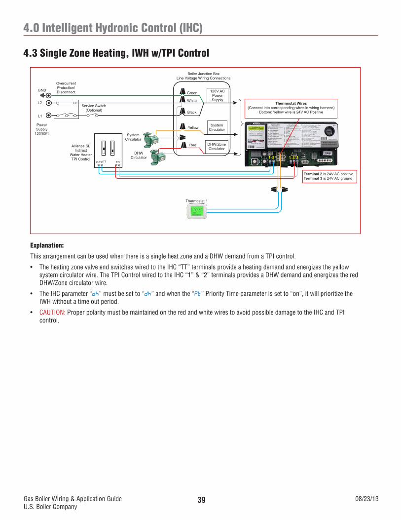
4.3 Single Zone Heating, IWH w/TPI Control
120V ACPowerSupply
SystemCirculator
DHW/ZoneCirculator
Boiler Junction BoxLine Voltage Wiring Connections
Green
White
Black
Yellow
Service Switch(Optional)
OvercurrentProtection/DisconnectGND
L2
L1
PowerSupply
120/60/1
Thermostat 1
1 2 1 2 3
Red
Thermostat Wires(Connect into corresponding wires in wiring harness)
Bottom: Yellow wire is 24V AC Positive
Alliance SLIndirect
Water HeaterTPI Control
Terminal 2 is 24V AC positiveTerminal 3 is 24V AC ground
SystemCirculator
DHWCirculator
24Vpump/TT
Explanation:
This arrangement can be used when there is a single heat zone and a DHW demand from a TPI control.
• TheheatingzonevalveendswitcheswiredtotheIHC“TT”terminalsprovideaheatingdemandandenergizestheyellowsystem circulator wire. The TPI Control wired to the IHC “1” & “2” terminals provides a DHW demand and energizes the red DHW/Zone circulator wire.
• TheIHCparameter“dh” must be set to “dh” and when the “Pt” Priority Time parameter is set to “on”, it will prioritize the IWH without a time out period.
• CAUTION: Proper polarity must be maintained on the red and white wires to avoid possible damage to the IHC and TPI control.
Gas Boiler Wiring & Application GuideU.S. Boiler Company
08/23/1340
4.0 Intelligent Hydronic Control (IHC)
4.4 Single Zone Heating, IWH w/TPI Control
120V ACPowerSupply
SystemCirculator
DHW/ZoneCirculator
Boiler Junction BoxLine Voltage Wiring Connections
Green
White
Black
Yellow
Service Switch(Optional)
OvercurrentProtection/DisconnectGND
L2
L1
PowerSupply
120/60/1
Thermostat 1
1 2 1 2 3
Red
Thermostat Wires(Connect into corresponding wires in wiring harness)
Bottom: Yellow wire is 24V AC Positive
IWH Aquastat Controls
SystemCirculator
DHWCirculator
Explanation:
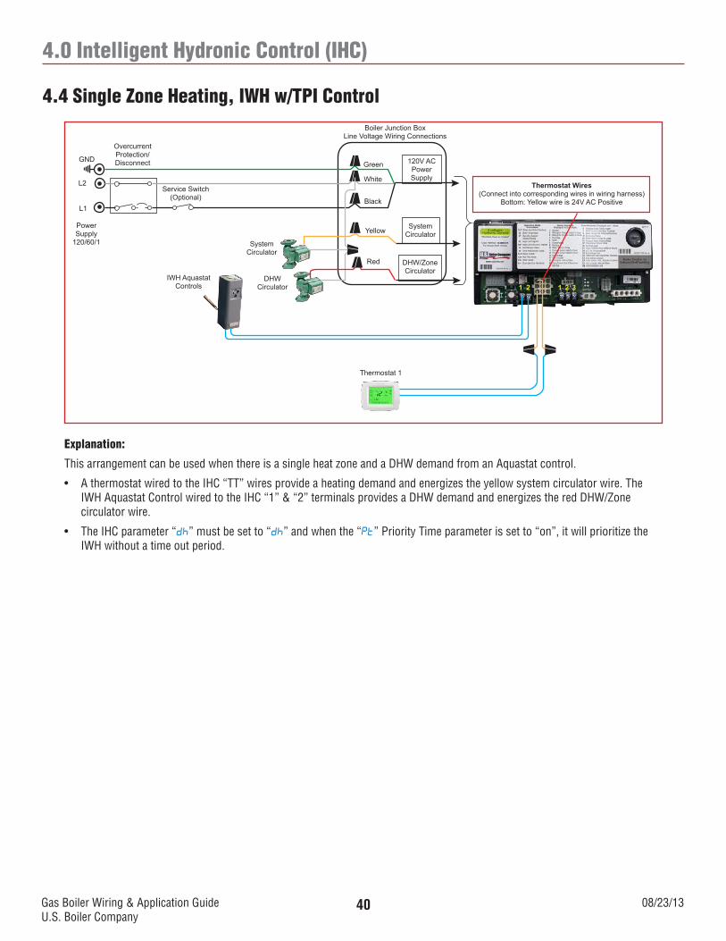
This arrangement can be used when there is a single heat zone and a DHW demand from an Aquastat control.
• AthermostatwiredtotheIHC“TT”wiresprovideaheatingdemandandenergizestheyellowsystemcirculatorwire.TheIWH Aquastat Control wired to the IHC “1” & “2” terminals provides a DHW demand and energizes the red DHW/Zone circulator wire.
• TheIHCparameter“dh” must be set to “dh” and when the “Pt” Priority Time parameter is set to “on”, it will prioritize the IWH without a time out period.
Gas Boiler Wiring & Application GuideU.S. Boiler Company
08/23/1341
4.0 Intelligent Hydronic Control (IHC)
4.5 Two Zone Heating
120V ACPowerSupply
SystemCirculator
DHW/ZoneCirculator
Boiler Junction BoxLine Voltage Wiring Connections
Green
White
Black
Yellow
Service Switch(Optional)
OvercurrentProtection/DisconnectGND
L2
L1
PowerSupply
120/60/1
Thermostat 1
1 2 1 2 3
Red
Thermostat Wires(Connect into corresponding wires in wiring harness)
Bottom: Yellow wire is 24V AC Positive
Zone 1Circulator
Zone 2Circulator
Thermostat 2
Explanation:
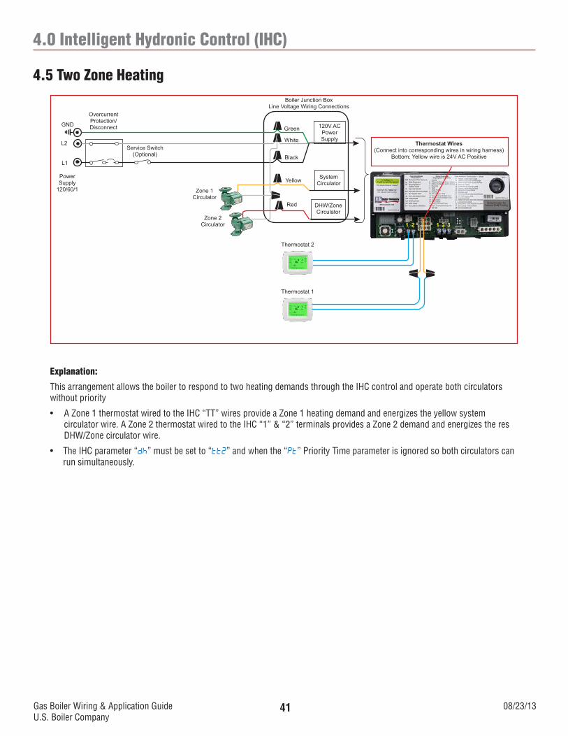
This arrangement allows the boiler to respond to two heating demands through the IHC control and operate both circulators without priority
• AZone1thermostatwiredtotheIHC“TT”wiresprovideaZone1heatingdemandandenergizestheyellowsystem circulator wire. A Zone 2 thermostat wired to the IHC “1” & “2” terminals provides a Zone 2 demand and energizes the res DHW/Zone circulator wire.
• TheIHCparameter“dh” must be set to “tt2” and when the “Pt” Priority Time parameter is ignored so both circulators can run simultaneously.
Gas Boiler Wiring & Application GuideU.S. Boiler Company
08/23/1342
4.0 Intelligent Hydronic Control (IHC)
4.6 Zone Valve Heating
120V ACPowerSupply
SystemCirculator
DHW/ZoneCirculator
Boiler Junction BoxLine Voltage Wiring Connections
Green
White
Black
Yellow
Service Switch(Optional)
OvercurrentProtection/DisconnectGND
L2
L1
PowerSupply
120/60/1
1 2 1 2 3
Red
Thermostat Wires(Connect into corresponding wires in wiring harness)
Bottom: Yellow wire is 24V AC Positive
SystemCirculator
Thermostat 3Thermostat 2Thermostat 1
24V AC Positive
40VA Transformer
Field Installed
Power Supply
120/60/1
L1L2
NOTEZone Valve Terminal 2 must be
connected to 24V ACCommon failure to do so will result in
damaged equipment
Explanation:
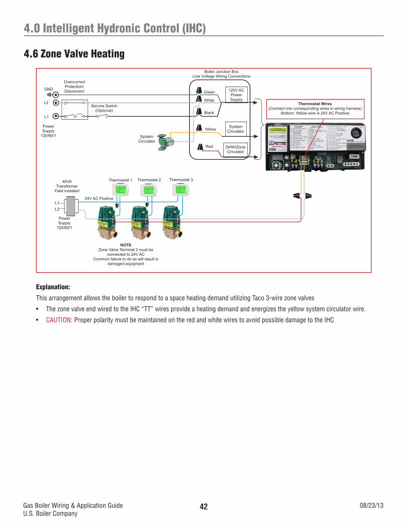
This arrangement allows the boiler to respond to a space heating demand utilizing Taco 3-wire zone valves
• ThezonevalveendwiredtotheIHC“TT”wiresprovideaheatingdemandandenergizestheyellowsystemcirculatorwire.
• CAUTION: Proper polarity must be maintained on the red and white wires to avoid possible damage to the IHC
Gas Boiler Wiring & Application GuideU.S. Boiler Company
08/23/1343
4.0 Intelligent Hydronic Control (IHC)
4.7 Zone Valve Heating, IWH w/TPI Control, 2 Circulators
120V ACPowerSupply
SystemCirculator
DHW/ZoneCirculator
Boiler Junction BoxLine Voltage Wiring Connections
Green
White
Black
Yellow
Service Switch(Optional)
OvercurrentProtection/DisconnectGND
L2
L1
PowerSupply
120/60/1
1 2 1 2 3
Red
Thermostat Wires(Connect into corresponding wires in wiring harness)
Bottom: Yellow wire is 24V AC Positive
Thermostat 3Thermostat 2Thermostat 1
24V AC Positive
40VA Transformer
Field Installed
Power Supply
120/60/1
L1L2
NOTEZone Valve Terminal 2 must be
connected to 24V ACCommon failure to do so will result in
damaged equipment
DHWCirculator
Alliance SLIndirect
Water HeaterTPI Control
SystemCirculator
24Vpump/TT
Explanation:
This arrangement allows the boiler to respond to a space heating demand utilizing Taco 3-wire zone valves and a DHW demand from a TPI control.
• ThezonevalveendwiredtotheIHC“TT”wiresprovideaheatingdemandandenergizestheyellowsystemcirculatorwire. The TPI Control wired to the IHC “1” & “2” terminals provides a Zone 2 demand and energizes the red DHW/Zone circulator wire.
• TheIHCparameter“dh” must be set to “dh” and when the “Pt” Priority Time parameter is set to “on”, it will prioritize the IWH without a time out period
• CAUTION: Proper polarity must be maintained on the red and white wires to avoid possible damage to the IHC and TPI control.
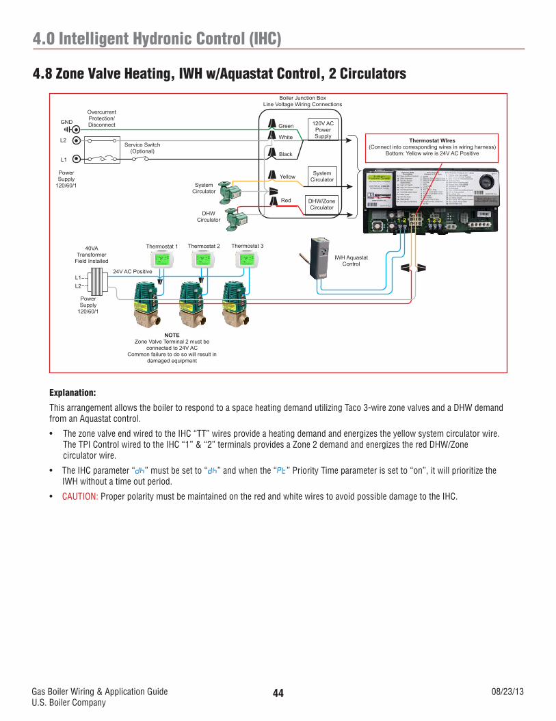
Gas Boiler Wiring & Application GuideU.S. Boiler Company
08/23/1344
4.0 Intelligent Hydronic Control (IHC)
4.8 Zone Valve Heating, IWH w/Aquastat Control, 2 Circulators
120V ACPowerSupply
SystemCirculator
DHW/ZoneCirculator
Boiler Junction BoxLine Voltage Wiring Connections
Green
White
Black
Yellow
Service Switch(Optional)
OvercurrentProtection/DisconnectGND
L2
L1
PowerSupply
120/60/1
1 2 1 2 3
Red
Thermostat WIres(Connect into corresponding wires in wiring harness)
Bottom: Yellow wire is 24V AC Positive
Thermostat 3Thermostat 2Thermostat 1
24V AC Positive
40VA Transformer
Field Installed
Power Supply
120/60/1
L1L2
NOTEZone Valve Terminal 2 must be
connected to 24V ACCommon failure to do so will result in
damaged equipment
DHWCirculator
SystemCirculator
IWH Aquastat Control
Explanation:
This arrangement allows the boiler to respond to a space heating demand utilizing Taco 3-wire zone valves and a DHW demand from an Aquastat control.
• ThezonevalveendwiredtotheIHC“TT”wiresprovideaheatingdemandandenergizestheyellowsystemcirculatorwire. The TPI Control wired to the IHC “1” & “2” terminals provides a Zone 2 demand and energizes the red DHW/Zone circulator wire.
• TheIHCparameter“dh” must be set to “dh” and when the “Pt” Priority Time parameter is set to “on”, it will prioritize the IWH without a time out period.
• CAUTION: Proper polarity must be maintained on the red and white wires to avoid possible damage to the IHC.
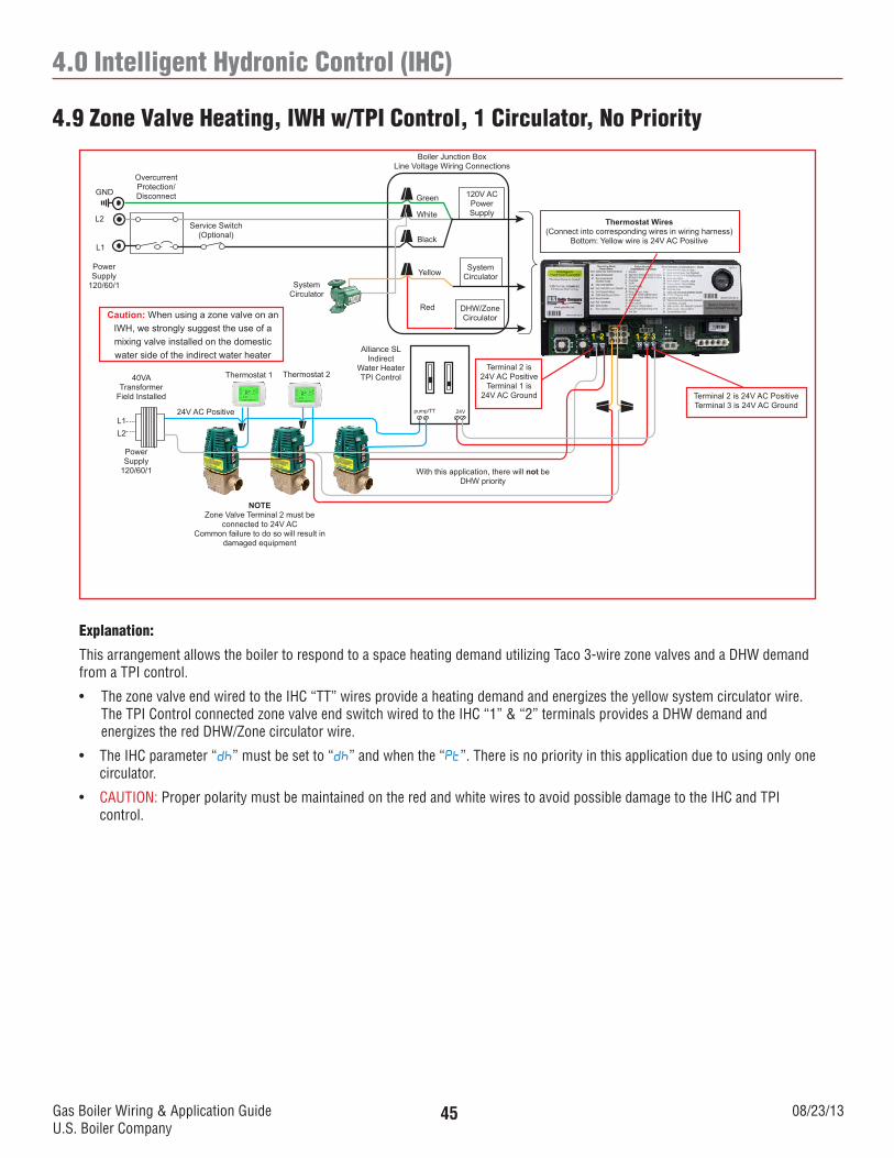
Gas Boiler Wiring & Application GuideU.S. Boiler Company
08/23/1345
4.0 Intelligent Hydronic Control (IHC)
4.9 Zone Valve Heating, IWH w/TPI Control, 1 Circulator, No Priority
120V ACPowerSupply
SystemCirculator
DHW/ZoneCirculator
Boiler Junction BoxLine Voltage Wiring Connections
Green
White
Black
Yellow
Service Switch(Optional)
OvercurrentProtection/DisconnectGND
L2
L1
PowerSupply
120/60/1
1 2 1 2 3
Red
Thermostat Wires(Connect into corresponding wires in wiring harness)
Bottom: Yellow wire is 24V AC Positive
Thermostat 2Thermostat 1
24V AC Positive
40VA Transformer
Field Installed
Power Supply
120/60/1
L1L2
NOTEZone Valve Terminal 2 must be
connected to 24V ACCommon failure to do so will result in
damaged equipment
SystemCirculator
Alliance SLIndirect
Water HeaterTPI Control
With this application, there will not be DHW priority
Caution: When using a zone valve on an IWH, we strongly suggest the use of a mixing valve installed on the domestic water side of the indirect water heater
Terminal 2 is 24V AC PositiveTerminal 3 is 24V AC Ground
Terminal 2 is 24V AC Positive
Terminal 1 is 24V AC Ground
24Vpump/TT
Explanation:
This arrangement allows the boiler to respond to a space heating demand utilizing Taco 3-wire zone valves and a DHW demand from a TPI control.
• ThezonevalveendwiredtotheIHC“TT”wiresprovideaheatingdemandandenergizestheyellowsystemcirculatorwire. The TPI Control connected zone valve end switch wired to the IHC “1” & “2” terminals provides a DHW demand and energizes the red DHW/Zone circulator wire.
• TheIHCparameter“dh” must be set to “dh” and when the “Pt”. There is no priority in this application due to using only one circulator.
• CAUTION: Proper polarity must be maintained on the red and white wires to avoid possible damage to the IHC and TPI control.
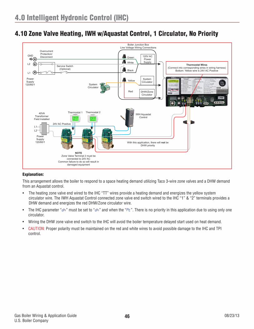
Gas Boiler Wiring & Application GuideU.S. Boiler Company
08/23/1346
4.0 Intelligent Hydronic Control (IHC)
4.10 Zone Valve Heating, IWH w/Aquastat Control, 1 Circulator, No Priority
120V ACPowerSupply
SystemCirculator
DHW/ZoneCirculator
Boiler Junction BoxLine Voltage Wiring Connections
Green
White
Black
Yellow
Service Switch(Optional)
OvercurrentProtection/DisconnectGND
L2
L1
PowerSupply
120/60/1
1 2 1 2 3
Red
Thermostat 2Thermostat 1
24V AC Positive
40VA Transformer
Field Installed
Power Supply
120/60/1
L1L2
NOTEZone Valve Terminal 2 must be
connected to 24V ACCommon failure to do so will result in
damaged equipment
SystemCirculator
With this application, there will not be DHW priority
IWH Aquastat Control
Thermostat Wires(Connect into corresponding wires in wiring harness)
Bottom: Yellow wire is 24V AC Positive
Explanation:
This arrangement allows the boiler to respond to a space heating demand utilizing Taco 3-wire zone valves and a DHW demand from an Aquastat control.
• TheheatingzonevalveendwiredtotheIHC“TT”wiresprovideaheatingdemandandenergizestheyellowsystem circulator wire. The IWH Aquastat Control connected zone valve end switch wired to the IHC “1” & “2” terminals provides a DHW demand and energizes the red DHW/Zone circulator wire.
• TheIHCparameter“dh” must be set to “dh” and when the “Pt”. There is no priority in this application due to using only one circulator.
• WiringtheDHWzonevalveendswitchtotheIHCwillavoidtheboilertemperaturedelayedstartusedonheatdemand.
• CAUTION: Proper polarity must be maintained on the red and white wires to avoid possible damage to the IHC and TPI control.
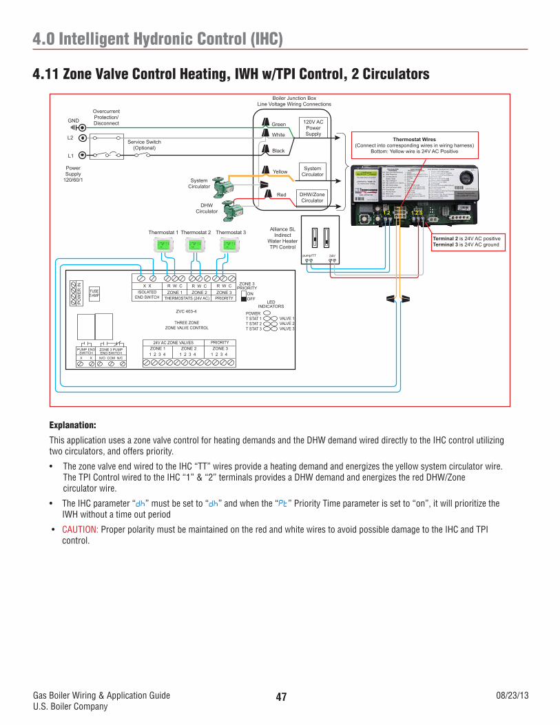
Gas Boiler Wiring & Application GuideU.S. Boiler Company
08/23/1347
4.0 Intelligent Hydronic Control (IHC)
4.11 Zone Valve Control Heating, IWH w/TPI Control, 2 Circulators
Thermostat 1 Thermostat 2
X X R W C R W C R W CZONE 1 ZONE 2 ZONE 3
THERMOSTATS (24V AC) PRIORITYISOLATED
END SWITCH
ZVC 403-4
THREE ZONEZONE VALVE CONTROL
ZONE 1 ZONE 2 ZONE 3PRIORITY24V AC ZONE VALVES
1 2 3 4 1 2 3 41 2 3 4
ZONE 3PRIORITY
ONOFF
LEDINDICATORS
POWERT STAT 1T STAT 2T STAT 3
VALVE 1VALVE 2VALVE 3
FUSE5 AMP
PO
WE
R IN
ZONE 3 PUMPEND SWITCH
PUMP END SWITCH
N/O COM N/CX X
1 2 1 2 3
120V ACPowerSupply
SystemCirculator
DHW/ZoneCirculator
Boiler Junction BoxLine Voltage Wiring Connections
Green
White
Black
Yellow
SystemCirculator
Service Switch(Optional)
OvercurrentProtection/DisconnectGND
L2
L1
PowerSupply
120/60/1
Red
DHWCirculator
Alliance SLIndirect
Water HeaterTPI Control
Thermostat 3Terminal 2 is 24V AC positiveTerminal 3 is 24V AC ground
24Vpump/TT
Thermostat Wires(Connect into corresponding wires in wiring harness)
Bottom: Yellow wire is 24V AC Positive
Explanation:
This application uses a zone valve control for heating demands and the DHW demand wired directly to the IHC control utilizing two circulators, and offers priority.
• ThezonevalveendwiredtotheIHC“TT”wiresprovideaheatingdemandandenergizestheyellowsystemcirculatorwire. The TPI Control wired to the IHC “1” & “2” terminals provides a DHW demand and energizes the red DHW/Zone circulator wire.
• TheIHCparameter“dh” must be set to “dh” and when the “Pt” Priority Time parameter is set to “on”, it will prioritize the IWH without a time out period
• CAUTION: Proper polarity must be maintained on the red and white wires to avoid possible damage to the IHC and TPI control.
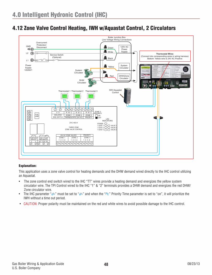
Gas Boiler Wiring & Application GuideU.S. Boiler Company
08/23/1348
4.0 Intelligent Hydronic Control (IHC)
4.12 Zone Valve Control Heating, IWH w/Aquastat Control, 2 Circulators
Thermostat 1 Thermostat 2
X X R W C R W C R W CZONE 1 ZONE 2 ZONE 3
THERMOSTATS (24V AC) PRIORITYISOLATED
END SWITCH
ZVC 403-4
THREE ZONEZONE VALVE CONTROL
ZONE 1 ZONE 2 ZONE 3PRIORITY24V AC ZONE VALVES
1 2 3 4 1 2 3 41 2 3 4
ZONE 3PRIORITY
ONOFF
LEDINDICATORS
POWERT STAT 1T STAT 2T STAT 3
VALVE 1VALVE 2VALVE 3
FUSE5 AMP
PO
WE
R IN
ZONE 3 PUMPEND SWITCH
PUMP END SWITCH
N/O COM N/CX X
1 2 1 2 3
120V ACPowerSupply
SystemCirculator
DHW/ZoneCirculator
Boiler Junction BoxLine Voltage Wiring Connections
Green
White
Black
Yellow
SystemCirculator
Service Switch(Optional)
OvercurrentProtection/DisconnectGND
L2
L1
PowerSupply
120/60/1
Red
DHWCirculator
Thermostat 3 IWH Aquastat Control
Thermostat Wires(Connect into corresponding wires in wiring harness)
Bottom: Yellow wire is 24V AC Positive
Explanation:
This application uses a zone valve control for heating demands and the DHW demand wired directly to the IHC control utilizing an Aquastat.
• ThezonecontrolendswitchwiredtotheIHC“TT”wiresprovideaheatingdemandandenergizestheyellowsystem circulator wire. The TPI Control wired to the IHC “1” & “2” terminals provides a DHW demand and energizes the red DHW/ Zone circulator wire.• TheIHCparameter“dh” must be set to “dh” and when the “Pt” Priority Time parameter is set to “on”, it will prioritize the
IWH without a time out period.
• CAUTION: Proper polarity must be maintained on the red and white wires to avoid possible damage to the IHC control.
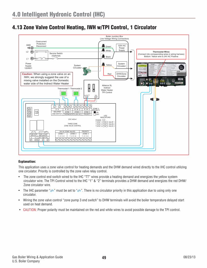
Gas Boiler Wiring & Application GuideU.S. Boiler Company
08/23/1349
4.0 Intelligent Hydronic Control (IHC)
4.13 Zone Valve Control Heating, IWH w/TPI Control, 1 Circulator
Thermostat 1 Thermostat 2
X X R W C R W C R W CZONE 1 ZONE 2 ZONE 3
THERMOSTATS (24V AC) PRIORITYISOLATED
END SWITCH
ZVC 403-4
THREE ZONEZONE VALVE CONTROL
ZONE 1 ZONE 2 ZONE 3PRIORITY24V AC ZONE VALVES
1 2 3 4 1 2 3 41 2 3 4
ZONE 3PRIORITY
ONOFF
LEDINDICATORS
POWERT STAT 1T STAT 2T STAT 3
VALVE 1VALVE 2VALVE 3
FUSE5 AMP
PO
WE
R IN
ZONE 3 PUMPEND SWITCH
PUMP END SWITCH
N/O COM N/CX X
1 2 1 2 3
120V ACPowerSupply
SystemCirculator
DHW/ZoneCirculator
Boiler Junction BoxLine Voltage Wiring Connections
Green
White
Black
YellowSystemCirculator
Service Switch(Optional)
OvercurrentProtection/DisconnectGND
L2
L1
PowerSupply
120/60/1
RedCaution: When using a zone valve on an IWH, we strongly suggest the use of a mixing valve installed on the Domestic water side of the Indirect Water Heater
Alliance SLIndirect
Water HeaterTPI Control
Thermostat Wires(Connect into corresponding wires in wiring harness)
Bottom: Yellow wire is 24V AC Positive
24Vpump/TT
Explanation:
This application uses a zone valve control for heating demands and the DHW demand wired directly to the IHC control utilizing one circulator. Priority is controlled by the zone valve relay control.
• ThezonecontrolendswitchwiredtotheIHC“TT”wiresprovideaheatingdemandandenergizestheyellowsystem circulator wire. The TPI Control wired to the IHC “1” & “2” terminals provides a DHW demand and energizes the red DHW/ Zone circulator wire.
• TheIHCparameter“dh” must be set to “dh”. There is no circulator priority in this application due to using only one circulator.
• Wiringthezonevalvecontrol“zonepump3endswitch”toDHWterminalswillavoidtheboilertemperaturedelayedstartused on heat demand.
• CAUTION: Proper polarity must be maintained on the red and white wires to avoid possible damage to the TPI control.
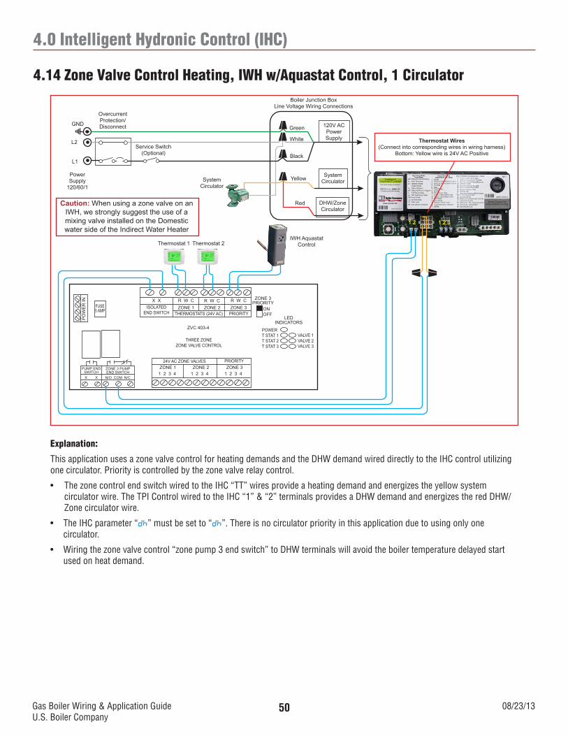
Gas Boiler Wiring & Application GuideU.S. Boiler Company
08/23/1350
4.0 Intelligent Hydronic Control (IHC)
4.14 Zone Valve Control Heating, IWH w/Aquastat Control, 1 Circulator
Thermostat 1 Thermostat 2
X X R W C R W C R W CZONE 1 ZONE 2 ZONE 3
THERMOSTATS (24V AC) PRIORITYISOLATED
END SWITCH
ZVC 403-4
THREE ZONEZONE VALVE CONTROL
ZONE 1 ZONE 2 ZONE 3PRIORITY24V AC ZONE VALVES
1 2 3 4 1 2 3 41 2 3 4
ZONE 3PRIORITY
ONOFF
LEDINDICATORS
POWERT STAT 1T STAT 2T STAT 3
VALVE 1VALVE 2VALVE 3
FUSE5 AMP
PO
WE
R IN
ZONE 3 PUMPEND SWITCH
PUMP END SWITCH
N/O COM N/CX X
1 2 1 2 3
120V ACPowerSupply
SystemCirculator
DHW/ZoneCirculator
Boiler Junction BoxLine Voltage Wiring Connections
Green
White
Black
YellowSystemCirculator
Service Switch(Optional)
OvercurrentProtection/DisconnectGND
L2
L1
PowerSupply
120/60/1
RedCaution: When using a zone valve on an IWH, we strongly suggest the use of a mixing valve installed on the Domestic water side of the Indirect Water Heater
IWH Aquastat Control
Thermostat Wires(Connect into corresponding wires in wiring harness)
Bottom: Yellow wire is 24V AC Positive
Explanation:
This application uses a zone valve control for heating demands and the DHW demand wired directly to the IHC control utilizing one circulator. Priority is controlled by the zone valve relay control.
• ThezonecontrolendswitchwiredtotheIHC“TT”wiresprovideaheatingdemandandenergizestheyellowsystem circulator wire. The TPI Control wired to the IHC “1” & “2” terminals provides a DHW demand and energizes the red DHW/ Zone circulator wire.
• TheIHCparameter“dh” must be set to “dh”. There is no circulator priority in this application due to using only one circulator.
• Wiringthezonevalvecontrol“zonepump3endswitch”toDHWterminalswillavoidtheboilertemperaturedelayedstartused on heat demand.
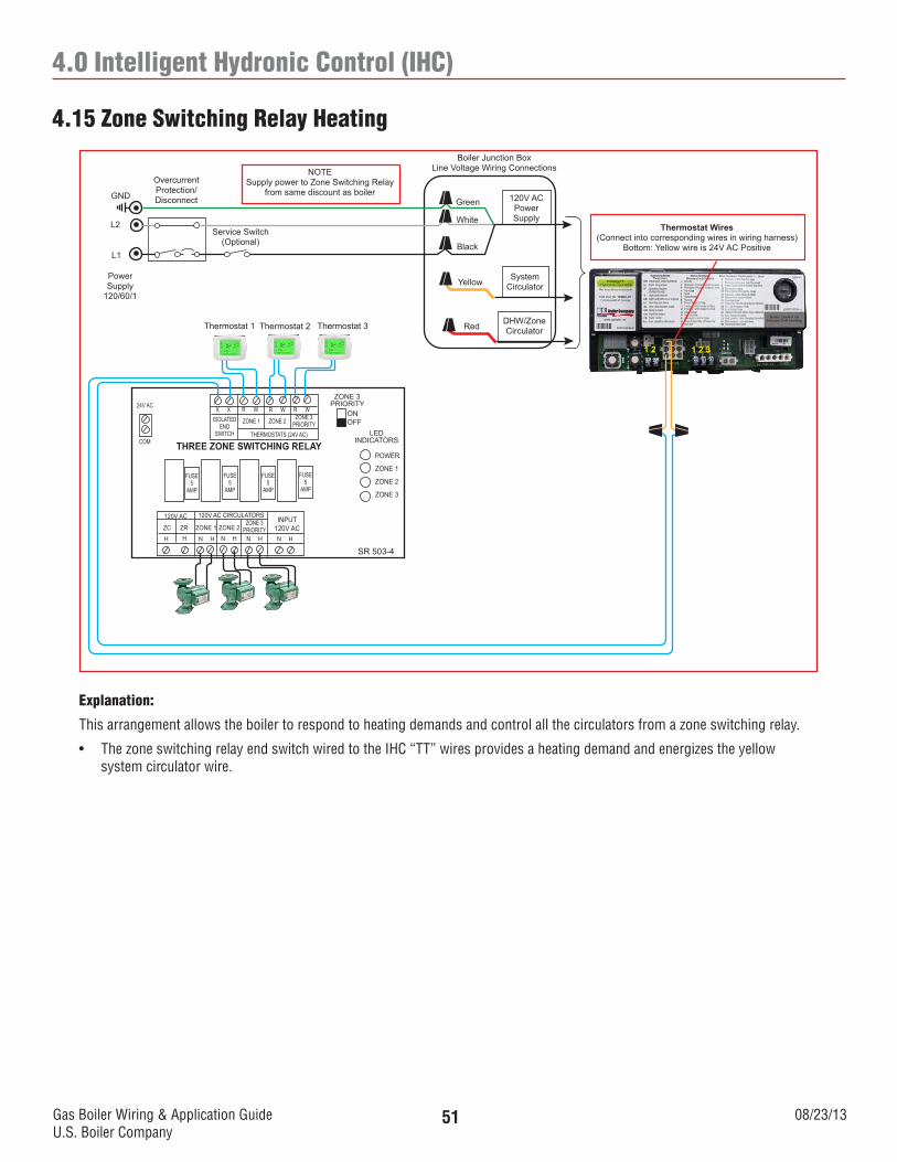
Gas Boiler Wiring & Application GuideU.S. Boiler Company
08/23/1351
4.0 Intelligent Hydronic Control (IHC)
4.15 Zone Switching Relay Heating
120V ACPowerSupply
SystemCirculator
DHW/ZoneCirculator
Boiler Junction BoxLine Voltage Wiring Connections
Green
White
Black
Yellow
Service Switch(Optional)
OvercurrentProtection/DisconnectGND
L2
L1
PowerSupply
120/60/1
Thermostat 1 Thermostat 2
ISOLATEDEND
SWITCH
SR 503-4
THREE ZONE SWITCHING RELAYLED
INDICATORS
POWER
ZONE 1
ZONE 2
ZONE 3
FUSE5
AMP
1 2 1 2 3
Thermostat 3
X X R W R W R W
ZONE 1 ZONE 2 ZONE 3PRIORITY
THERMOSTATS (24V AC)
FUSE5
AMP
FUSE5
AMP
FUSE5
AMP
ZONE 3PRIORITY
ONOFF
24V AC
COM
INPUT120V AC
120V AC CIRCULATORS120V AC
ZC ZR ZONE 1 ZONE 2ZONE 3
PRIORITYH H N H N H N H N H
Red
NOTESupply power to Zone Switching Relay
from same discount as boiler
Thermostat Wires(Connect into corresponding wires in wiring harness)
Bottom: Yellow wire is 24V AC Positive
Explanation:
This arrangement allows the boiler to respond to heating demands and control all the circulators from a zone switching relay.
• ThezoneswitchingrelayendswitchwiredtotheIHC“TT”wiresprovidesaheatingdemandandenergizestheyellow system circulator wire.
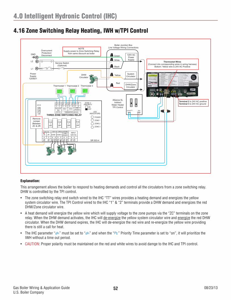
Gas Boiler Wiring & Application GuideU.S. Boiler Company
08/23/1352
4.0 Intelligent Hydronic Control (IHC)
4.16 Zone Switching Relay Heating, IWH w/TPI Control
120V ACPowerSupply
SystemCirculator
DHW/ZoneCirculator
Boiler Junction BoxLine Voltage Wiring Connections
Green
White
Black
Yellow
Service Switch(Optional)
OvercurrentProtection/DisconnectGND
L2
L1
PowerSupply
120/60/1
Thermostat 1 Thermostat 2
ISOLATEDEND
SWITCH
SR 503-4
THREE ZONE SWITCHING RELAYLED
INDICATORS
POWER
ZONE 1
ZONE 2
ZONE 3
FUSE5
AMP
1 2 1 2 3
Thermostat 3
X X R W R W R W
ZONE 1 ZONE 2 ZONE 3PRIORITY
THERMOSTATS (24V AC)
FUSE5
AMP
FUSE5
AMP
FUSE5
AMP
ZONE 3PRIORITY
ONOFF
24V AC
COM
INPUT120V AC
120V AC CIRCULATORS120V AC
ZC ZR ZONE 1 ZONE 2ZONE 3
PRIORITYH H N H N H N H N H
Red
NOTESupply power to Zone Switching Relay
from same discount as boiler
Alliance SLIndirect
Water HeaterTPI Control
DHWCirculator
Remove Jumper
Between ZC & 2R
Terminal 2 is 24V AC positiveTerminal 3 is 24V AC ground
Thermostat Wires(Connect into corresponding wires in wiring harness)
Bottom: Yellow wire is 24V AC Positive
24Vpump/TT
Explanation:
This arrangement allows the boiler to respond to heating demands and control all the circulators from a zone switching relay. DHW is controllled by the TPI control.
• ThezoneswitchingrelayendswitchwiredtotheIHC“TT”wiresprovidesaheatingdemandandenergizestheyellowsystem circulator wire. The TPI Control wired to the IHC “1” & “2” terminals provide a DHW demand and energizes the red DHW/Zone circulator wire.
• Aheatdemandwillenergizetheyellowwirewhichwillsupplyvoltagetothezonepumpsviathe“ZC”terminalsonthezonerelay. When the DHW demand activates, the IHC will de-energize the yellow system circulator wire and energize the red DHW circulator. When the DHW demand expires, the IHC will de-energize the red wire and re-energize the yellow wire providing there is still a call for heat.
• TheIHCparameter“dh” must be set to “dh” and when the “Pt” Priority Time parameter is set to “on”, it will prioritize the IWH without a time out period.
• CAUTION: Proper polarity must be maintained on the red and white wires to avoid damge to the IHC and TPI control.
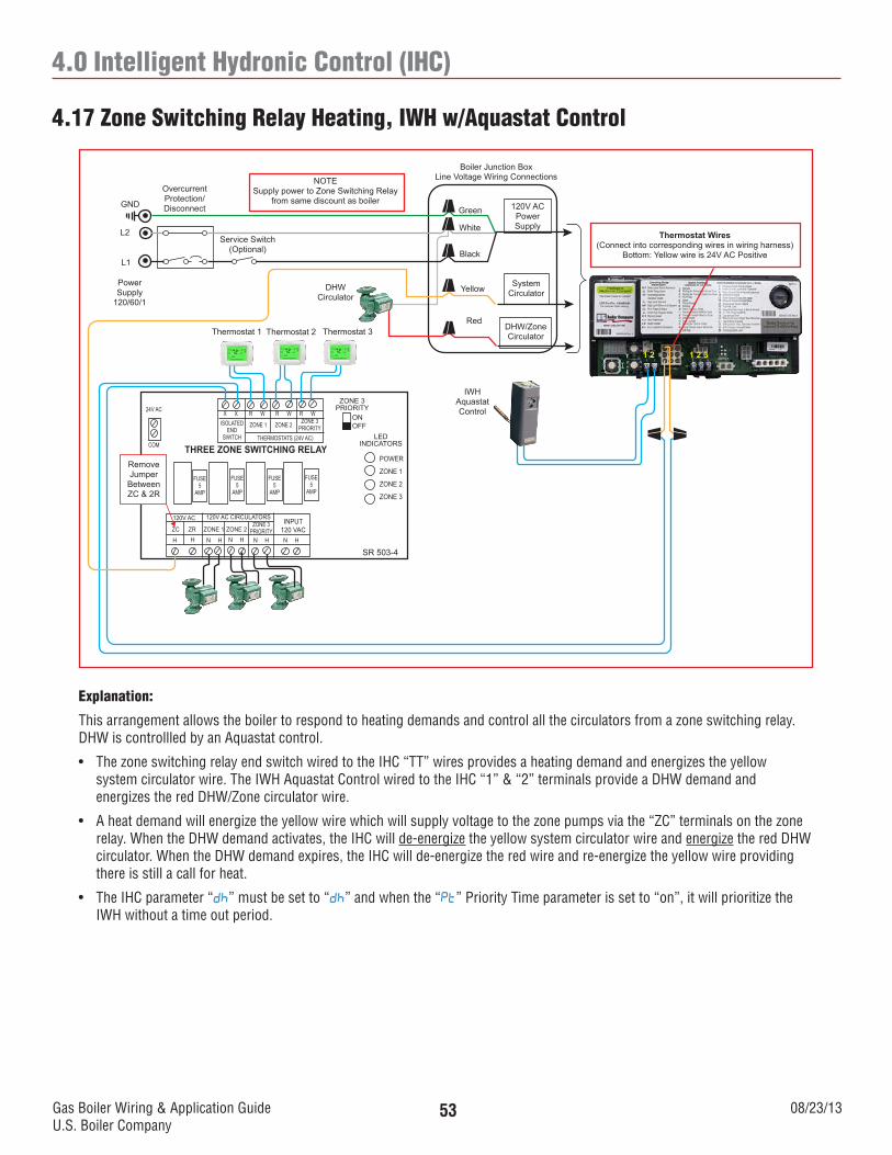
Gas Boiler Wiring & Application GuideU.S. Boiler Company
08/23/1353
4.0 Intelligent Hydronic Control (IHC)
4.17 Zone Switching Relay Heating, IWH w/Aquastat Control
120V ACPowerSupply
SystemCirculator
DHW/ZoneCirculator
Boiler Junction BoxLine Voltage Wiring Connections
Green
White
Black
Yellow
Service Switch(Optional)
OvercurrentProtection/DisconnectGND
L2
L1
PowerSupply
120/60/1
Thermostat 1 Thermostat 2
ISOLATEDEND
SWITCH
SR 503-4
THREE ZONE SWITCHING RELAYLED
INDICATORS
POWER
ZONE 1
ZONE 2
ZONE 3
FUSE5
AMP
1 2 1 2 3
Thermostat 3
X X R W R W R W
ZONE 1 ZONE 2 ZONE 3PRIORITY
THERMOSTATS (24V AC)
FUSE5
AMP
FUSE5
AMP
FUSE5
AMP
ZONE 3PRIORITY
ONOFF
24V AC
COM
INPUT120 VAC
120V AC CIRCULATORS120V AC
ZC ZR ZONE 1 ZONE 2ZONE 3
PRIORITYH H N H N H N H N H
Red
NOTESupply power to Zone Switching Relay
from same discount as boiler
DHWCirculator
Remove Jumper
Between ZC & 2R
IWH Aquastat Control
Thermostat Wires(Connect into corresponding wires in wiring harness)
Bottom: Yellow wire is 24V AC Positive
Explanation:
This arrangement allows the boiler to respond to heating demands and control all the circulators from a zone switching relay. DHW is controllled by an Aquastat control.
• ThezoneswitchingrelayendswitchwiredtotheIHC“TT”wiresprovidesaheatingdemandandenergizestheyellowsystem circulator wire. The IWH Aquastat Control wired to the IHC “1” & “2” terminals provide a DHW demand and energizes the red DHW/Zone circulator wire.
• Aheatdemandwillenergizetheyellowwirewhichwillsupplyvoltagetothezonepumpsviathe“ZC”terminalsonthezonerelay. When the DHW demand activates, the IHC will de-energize the yellow system circulator wire and energize the red DHW circulator. When the DHW demand expires, the IHC will de-energize the red wire and re-energize the yellow wire providing there is still a call for heat.
• TheIHCparameter“dh” must be set to “dh” and when the “Pt” Priority Time parameter is set to “on”, it will prioritize the IWH without a time out period.

Gas Boiler Wiring & Application GuideU.S. Boiler Company
08/23/1354
NOTES

Gas Boiler Wiring & Application GuideU.S. Boiler Company
08/23/1355
NOTES

Gas Boiler Wiring & Application GuideU.S. Boiler Company
08/23/1356
www.usboiler.net
ANYWHEREUNMATCHED