fuzzy controllers
TRANSCRIPT

Fuzzy Controllers
PRELIMS.PM5 6/13/97, 10:19 AM1

Tomy son Dmitry
and other students
PRELIMS.PM5 6/13/97, 10:19 AM2

Fuzzy Controllers
LEONID REZNIK
Victoria University of Technology,Melbourne, Australia
PRELIMS.PM5 6/13/97, 10:19 AM3

NewnesAn imprint of Butterworth-Heinemann
Linacre House, Jordan Hill, Oxford OX2 8DPA division of Reed Educational and Professional Publishing Ltd
A member of the Reed Elsevier plc group
OXFORD BOSTON JOHANNESBURGMELBOURNE NEW DELHI SINGAPORE
First published 1997
© Leonid Reznik 1997
All rights reserved. No part of this publication may bereproduced in any material form (including photocopying
or storing in any medium by electronic means and whetheror not transiently or incidentally to some other use ofthis publication) without the written permission of the
copyright holder except in accordance with the provisionsof the Copyright, Designs and Patents Act 1988 or underthe terms of a licence issued by the Copyright Licensing
Agency Ltd, 90 Tottenham Court Rd, London, England W1P 9HE.Applications for the copyright holder’s written permission
to reproduce any part of this publication should beaddressed to the publishers.
British Library Cataloguing in Publication DataA catalogue record for this book is available from the British Library
ISBN 0 7506 3429 4
Library of Congress Cataloguing in Publication DataA catalogue record for this book is available from the Library of Congress
Typeset by The Midlands Book Typesetting Company, Loughborough,Leicestershire, England
Printed in Great Britain by Biddles Ltd, Guildford and King’s Lynn
PRELIMS.PM5 6/13/97, 10:19 AM4

Contents
Foreword ixPreface xiAcknowledgements xiiiIntroduction xv
Part I How Does it Work? or The Theory ofFuzzy Control 1
1 Fuzzy sets, logic and control 31.1 Why do we need this new theory, what
are the advantages of fuzzy control? 31.2 Where does fuzzy logic come from? 51.3 What are the main areas of fuzzy
logic applications? 9
2 Basic mathematical concepts of fuzzy sets 192.1 Fuzzy sets versus crisp sets 192.2 Operations on fuzzy sets 302.3 Extension principle and fuzzy algebra 34
2.3.1 Extension principle 342.3.2 Fuzzy numbers 372.3.3 Arithmetic operations with
intervals of confidence 382.3.4 Arithmetic operations with
fuzzy numbers 412.4 Linguistic variables and hedges 442.5 Fuzzy relations 51
3 The structure and operation of a fuzzy controller 593.1 The reasons to apply fuzzy controllers 593.2 Fuzzy rules processing 61
3.2.1 Mamdani-type fuzzy processing 613.2.2 Linguistic variables 633.2.3 Fuzzy rules firing 653.2.4 Calculating the applicability degree 673.2.5 Clipping and scaling a fuzzy output 68
PRELIMS.PM5 6/13/97, 10:19 AM5
vi CONTENTS
3.2.6 Sugeno-type fuzzy processing 703.3 Fuzzy controllers operation 733.4 Structure of a simple open-loop fuzzy controller 743.5 Structure of a feedback PID-like fuzzy controller 78
3.5.1 Fuzzy controllers as a part of a feedbacksystem 78
3.5.2 PD-like fuzzy controller 793.5.3 Rules table notation 813.5.4 PI-like fuzzy controller 833.5.5 PID-like fuzzy controller 863.5.6 Combination of fuzzy and conventional
PID controllers 903.6 Stability and performance problems for a fuzzy
control system 933.6.1 Stability and performance evaluation
by observing the response 933.6.2 Stability and performance indicators 963.6.3 Stability evaluation by observing the
trajectory 983.6.4 Hierarchical fuzzy controllers 99
Part II How to Make it Work or The Designand Implementation of Fuzzy Controllers 105
4 Fuzzy controller parameter choice 1074.1 Practical examples 107
4.1.1 Fuzzy autopilot for a small marine vessel 1074.1.2 Smart heater control 1124.1.3 Active noise control 117
4.2 Iterative nature of a fuzzy controller design process 1214.3 Scaling factor choice 124
4.3.1 What is a scaling factor? 1244.3.2 Where should the tuning start? 1264.3.3 Application example 129
4.4 Membership function choice 1314.4.1 Distributing membership functions
on the universe of discourse? 1314.4.2 An evaluation of the membership
function width 1324.4.3 Application example 135
4.5 Fuzzy rule formulation 1364.5.1 Where do rules come from? 1364.5.2 How do we get rules? 1384.5.3 How do we check if the rules are OK? 139
PRELIMS.PM5 6/13/97, 10:19 AM6

CONTENTS vii
4.5.4 Application examples 1414.6. Choice of the defuzzification procedure 147
4.6.1 Centre-of area/gravity 1474.6.2 Centre-of-largest-area 1484.6.3 First-of-maxima/last-of-maxima 1494.6.4 Middle-of-maxima 1504.6.5 Mean-of-maxima 1504.6.6 Height 1514.6.7 Compare different defuzzification
procedures 151
5 Fuzzy controller parameter adjustment 1535.1 Self-organising, adaptive, and learning fuzzy
controllers: main principles and methods 1535.1.1 What do we need adjustments for? 1535.1.2 Self-organising fuzzy controllers 1545.1.3 Performance/robustness problem
and solutions 1545.1.4 Adaptive fuzzy controllers 1565.1.5 Features of different controller types 1585.1.6 Learning fuzzy controllers 159
5.2 Tuning of the fuzzy controller scaling factors 1605.2.1 On-line and off-line tuning 1605.2.2 Off-line tuning of the output
scaling factors 1605.2.3 On-line tuning of the input and output
scaling factors 1615.2.4 Application example 163
5.3 Artificial neural networks andneuro-fuzzy controllers 166
5.3.1 What is a neural network? 1665.3.2 ANN structure 1675.3.3 ANN types 1715.3.4 ANN application in fuzzy controller design 1745.3.5 ANFIS architecture 1755.3.6 Adaptive neuro-fuzzy controller 1765.3.7 Application examples 177
5.4 Adjustment procedures with genetic/evolutionaryalgorithms 180
5.4.1 How does it work? 1805.4.2 GA and EA application in fuzzy
controller design 1825.4.3 Application example 184
PRELIMS.PM5 6/13/97, 10:19 AM7

viii CONTENTS
6 Fuzzy system design software tools 1876.1 Fuzzy technology products classification 1876.2 Main features of the fuzzy software tools 1906.3 Realisation examples 191
7 Fuzzy controller implementation 2017.1 How do we implement a fuzzy controller? 2017.2 Implementation of a digital general purpose
processor 2027.3 Implementation of a digital specialised
processor 2057.4 Specialised processor development system 2097.5 Implementation on analog devices 2117.6 Integration of fuzzy and conventional
control hardware 214
Part III What Else Can I Use? or SupplementaryInformation 219
8 A brief manual to fuzzy controller design 2198.1 When to apply fuzzy controllers 2198.2. When not to apply fuzzy controllers 2198.3 Fuzzy controller operation 2208.4 Which fuzzy controller type to choose? 2238.5 Fuzzy controller structure and
parameter choice 2238.6 How to find membership functions 2258.7 How to find rules? 2268.8 How to implement a fuzzy controller 2268.9 How to test a fuzzy controller 2278.10 How to fix a fuzzy controller 2288.11 How to choose a design package 229
9 Problems and assignment topics 239
10 Design projects 253
11 Glossary 267
12 Bibliography 273
List of examples 283
Index 285
PRELIMS.PM5 6/13/97, 10:19 AM8

Foreword
Leonid Reznik’s Fuzzy Controllers is unlike any other book onfuzzy control. In its own highly informal, idiosyncractic and yetvery effective way, it succeeds in providing the reader with awealth of information about fuzzy controllers. It does so with aminimum of mathematics and a surfeit of examples, illustrationsand insightful descriptions of practical applications.
To view Fuzzy Controllers in a proper perspective a bit ofhistory is in order. When I wrote my paper on fuzzy sets in 1965,my expectation was that the theory of fuzzy sets would find itsmain applications in fields such as economics, biology, medicine,psychology and linguistics – fields in which the conventional,differential-equation-based approaches to systems analysis arelacking in effectiveness. The reason for ineffectiveness, as I sawit, is that in such fields the standard assumption that classes havesharply defined boundaries is not a good fit to reality. In thiscontext, it is natural to generalise the concept of a set byintroducing the concept of grade of membership or, equivalently,allowing the characteristic function of a set to take valuesintermediate between 0 and 1.
Since my background was in systems analysis, it did not takeme long to realise that the theory of fuzzy sets is of substantialrelevance to systems analysis and, especially, to control. Thisperception was articulated in my 1971 paper ‘Toward a theory offuzzy systems’, and 1972 paper, ‘A rationale for fuzzy control’.
The pivotal paper was my 1973 paper, ‘Outline of a newapproach to the analysis of complex systems and decisionprocesses’, in which the basic concepts and techniques thatunderlie most of the practical applications of fuzzy set theory (orfuzzy logic, as we call it today), were introduced. The conceptsin question are those of linguistic variable, fuzzy if-then rule andfuzzy rule sets. These concepts serve as the point of departure forwhat I call the theory of fuzzy information granulation. Thistheory postulates that in the context of fuzzy logic there are threebasic modes of generalisation of a theory, method or approach:(a) fuzzification, in which one or more crisp sets are replaced by
PRELIMS.PM5 6/13/97, 10:19 AM9

fuzzy sets; (b) granulation, in which an object is partitioned intoa collection of granules, with a granule being a clump of points(objects) drawn together by indistinguishability, similarity orfunctionality; and (c) fuzzy granulation, in which a crisp or fuzzyobject is partioned into fuzzy granules. In effect, fuzzyinformation granulation (f-granulation) is a combination offuzzification and granulation.
What has not been recognised to the extent that it should is thatthe successes of fuzzy logic involve not just fuzzification but,more importantly, fuzzy granulation. Furthermore, fuzzy logic isthe only methodology which provides a machinery for fuzzyinformation granulation. As we alluded to already, the keyconcepts underlying this machinery are those of linguisticvariable, fuzzy if-then rule and fuzzy rule sets. Basically, fuzzyrule sets or, equivalently, fuzzy graphs, serve to provide a way ofapproximating to a function or a relation by a disjunction ofCartesian products of values of linguistic variables.
Viewed against this backdrop, it is – in effect, though not byname – the machinery of fuzzy information granulation that isemployed in fuzzy controllers to explain – with high expositoryskills – what fuzzy controllers are, how they are designed, andhow they are used in real-world applications. One cannot but begreatly impressed by the profusion of examples, the up-to-datedness of information, lucidity of style and reader-friendlinessof Leonid Reznik’s exposition. His work should have strongappeal to anyone who is looking for a very informative and easyto understand introduction to fuzzy controllers and their role inthe conception, design and deployment of intelligent systems.
An issue of key importance in the design of fuzzy controllersis that of induction of rules from input-output data and tuning oftheir parameters. In the past, this was done by trial and error. Morerecently, techniques drawn from neurocomputing and geneticcomputing have been employed for this purpose. In FuzzyControllers, these techniques are discussed briefly but with insightin the last chapters. In these chapters, the reader will also find avery useful discussion of fuzzy system design software tools, theircapabilities and their applications.
In sum, this book is an unconventional and yet very informative,self-contained and reader-friendly introduction to the basics offuzzy logic and its application to the design of fuzzy controllers.Leonid Reznik deserves high marks for his achievement.
Lotfi A. ZadehBerkeley, CA
x FOREWORD
PRELIMS.PM5 6/13/97, 10:19 AM10

PREFACE
Since fuzzy logic was introduced by Lotfi Zadeh in 1965, ithas had many successful applications mostly in control. This‘fuzzy’ boom has generated strong interest in this area togetherwith a boom in studying and teaching of fuzzy theory andtechnology. Although a few books which can be used forteaching and learning are available on the market, what is stillmissed is an introductory textbook suitable for both under- andpostgraduate students, as well as for a beginner.
The aim of the book is to teach a reader how to design a fuzzycontroller and to share some experience in design andapplications. It can be used as a textbook by both teachers andstudents. Being an introduction this book tends to explain thingsstarting from basics roots and does not require any preliminaryknowledge in fuzzy theory and technology. I wanted to make thisbook different from other books available on the market. My goalswere:
to write a textbook that is intelligible even to a non-specialist;
to pay attention, first of all, to practical aspects of fuzzycontroller design;
to facilitate the learning and teaching process for both astudent and a teacher.
The structure of the book includes a description of the theoreticalfundamentals of fuzzy logic as well as study of practical aspectsof fuzzy technology. Consideration of all topics is practicallyoriented. This means that all the chapters work on achieving thefinal goal: to give a reader the knowledge necessary to design afuzzy control system. To become a real textbook which can beused for self-assessment and teaching, this book contains the listof problems, assignment topics and design projects.
The style of the book changes from a textbook at the beginning(when it discusses theoretical aspects of fuzzy control) to a
PRELIMS.PM5 6/13/97, 10:19 AM11

handbook (when it describes software and hardware tools whichcan be used in a fuzzy controller design). The book is written(especially at the beginning) as a discussion between a teacher andstudents who come from various educational and practicalbackgrounds and are supposed to be interested in different aspectsof fuzzy control theory and technology.
I wanted to avoid making this book dull and boring, so I havetried to apply ordinary (not scientific) language without losing acorrectness of mathematical determinations. It was very hardsometimes. That’s why a few chapters (especially Chapter 2)contain a number of mathematical definitions and otherconstructions. However, I tried to provide the reader with someexplanation about what all this mathematical stuff meant.
xii PREFACE
PRELIMS.PM5 6/13/97, 10:19 AM12

Acknowledgements
Many people from different countries and continents havecontributed generously to the creation of this book. Unfortunately,I am not able to name everybody who has made this undertakinghappen. It does not mean I do not remember all of you. Yourvaluable advice, encouragement and support is very muchappreciated. Let me use this small space to give those nameswhich I cannot miss.
A number of individuals, organisations and commercialcompanies have granted permission to reprint or adapt somematerial. I gratefully acknowledge the permission given by theInstitute of Electrical and Electronics Engineering, Inc.; AdaptiveLogic Inc.; David K. Kahaner, Director of Asian TechnologyInformation Program, Tokyo, Japan; INFORM GmbH, Aachen,Germany; Inform Software Corporation, Chicago, USA andConstantin von Altrock; CICS Automation, Newcastle, Australia andSam Crisafulli.
I wish to thank Professor Lotfi Zadeh for the invention of fuzzylogic and inspiration of this work as well as for finding time toread the manuscript and write this great foreword.
I would like to express my gratitude to my family, my parentsCarl and Ninel, my wife Olga and son Dmitry for their patience.
Finally I want to acknowledge great work of the editors andpublishers in shaping the manuscript and its preparation to thepublication.
FeedbackI shall appreciate receiving any comments regarding this book,especially from teachers and students. Please do not hesitate tocontact me directly or through the publishers.
Leonid ReznikVictoria University of TechnologyP.O. Box 14428 MCMC Melbourne 8001 Australia
Email: Leon [email protected]
PRELIMS.PM5 6/13/97, 10:19 AM13

PRELIMS.PM5 6/13/97, 10:19 AM14

INTRODUCTION
Could you teach us very quickly how to design a fuzzycontroller?
Well, it is not that easy…
Just explain a general method of design, optimisation, andimplementation.
I do not think there is a general method of designing andfinding optimal parameters for a fuzzy controller, because anysuch values always depend on the specific process or objectunder control and the control objectives. This is particularly thecase for a fuzzy controller where the design process is verysubjective.
However, I understand you want to start a designimmediately. As you know nothing about fuzzy control andfuzzy controllers, we will base our design just on our humanexperience. Let us consider a classical control problem. Wecontrol the boat movement which we should drive along thestraight line from point A to point B. How will you design acontroller to do it?
Well, firstly I must derive a mathematical model of the plant andthen develop a mathematical model of a controller.
And how will you develop this model?
I will apply one of the design methods, e.g., pole placementdesign, and obtain a transfer function for the controller.
OK. Now suppose we do not know exactly the mathematicalmodel of our plant. Moreover, we do not know any classicaldesign method. What can we do then?
Nothing. You have to know some theory. Otherwise you cannot doanything.
Try to use your own experience. How did you drive a boatin your childhood?
INTRO.PM5 6/12/97, 1:19 PM15

I turned the rudder left or right depending on the position of a boat.Great! So we can say that if the boat is situated exactly on the
line we should not do anything, if the boat is situated to the leftof the line we should turn the rudder to the right (let us call thisdirection positive), and if the boat is positioned to the right of theline we should turn the rudder to the left.
Now let us try to formulate this control law as a set of rules.
If deviation is zero then turn is zero.If deviation is positive then turn is negative.If deviation is negative then turn is positive.
We have formulated the set of the control rules which can bewritten as a table, which is a mathematical model of our controller.
No! A mathematical model is either an equation or amathematical function, or something like that.
Not necessarily. The mathematical model of a controllershould describe mapping of an input, in our case it is thedifference between the boat’s current position and the desiredone, to an output – control signal, in our case – the rudder angle.By using this table we can find the output corresponding to eachvalue of the input.
Are you sure this table can control the boat movement?Of course, very roughly. To improve the control quality and
make our controller more reactive, we need to increase thenumber of values describing each variable. Until now we havenot distinguished the values of the deviation and turn, but justconsidered their signs. Now let us use small, medium and bigvalues for both the deviation and the turn. Then we obtain therules table:
Deviation NB NM NS Z PS PM PB
Turn PB PM PS Z NS NM NB
How can we use this table? It just contains some abbreviationswhich I do not understand.
Actually these abbreviations represent the labels of fuzzyvalues. These labels give the ‘fuzzy’ value of the distance: big(PB and NB), medium (PM and NM), small (PS and NS), and
xvi INTRODUCTION
INTRO.PM5 6/12/97, 1:19 PM16

very small (Z). The prefixes P and N represent the side of the line,that our boat deviates to, right or left, positive or negative.
So we describe our controller with the help of the rules table.This is just a rules base controller. Where is the fuzzy logichidden?
In the processing of these rules. The problem of controllerdesign includes not just the compilation of the rules table, butalso the use of the table to calculate a control output. So weshould also say how to process these rules in order to get theoutput result, and this processing is based on the fuzzy theorymethods examined in Section 3.2. This describes the process ofproducing a fuzzy output from fuzzy inputs, which in the fuzzyset theory is called an inference engine.
Fuzzy inputs and outputs? Usually a controller uses measurementresults, doesn’t it? Are they fuzzy?
Not exactly. In fuzzy control, the measurement results orprocess outputs are generally assumed to be crisp, and areproduced by technical devices (sensors). On the other hand,controller outputs should also be crisp to control differenttechnical devices (actuators). It means that a fuzzy controllerneeds an interface at both input and output sides.
Have you started considering a structure of a fuzzy controller.Yes. The process of fuzzy reasoning or processing the fuzzy
rules is described in Section 3.2. Section 3.3 describes how atypical fuzzy controller operates. The structure of a simple fuzzycontroller is described in Section 3.4.
What is a typical fuzzy controller?It is not easy to define. We look at a PID-like fuzzy controller
structure (Section 3.5) which has proved to be very popular withdifferent designers in many applications. However, we proposea very brief consideration of more complicated structures andproblems in Sections 3.5 and 6. Section 3.6 explains how toimprove stability and performance of a fuzzy controller.
Both stability and performance?You are actually asking how to evaluate the quality of a fuzzy
controller design. In this book we are applying the criteriatraditionally used in control engineering, especially in practical
INTRODUCTION xvii
INTRO.PM5 6/12/97, 1:19 PM17

engineering, where one evaluates the controller performance basedon the system response obtained.
I see this book operates with some terms from control engineeringlike a PID-controller, for example.
Yes. Basically there are two approaches to a fuzzy controllerdesign: an expert approach and a control engineering approach. Inthe first (historically it was proposed earlier), the fuzzy controllerstructure and parameters choice are assumed to be the responsibilityof the experts. Consequently, design and performance of a fuzzycontroller depend mainly on the knowledge and experience of theexperts, or intuition and professional feeling of a designer. Thisdependence, which is considered far from systematic and reliable,is the flaw of this approach. Chapter 3 helps to construct a fuzzycontroller based on this experience. However, this approach couldassist in constructing a fuzzy model or an initial version of a fuzzycontroller.
The second approach supposes an application of theknowledge of control engineering and a design of a fuzzycontroller in some aspects similar to the conventional design withthe parameter’s choice, depending on the information of theirinfluence on the controller performance. This approach isconducted mainly in Chapter 4. This chapter opens Part II ofthe book, which is devoted to the problems of a fuzzy controllerdesign.
So how do you describe a design practice?A fuzzy controller design, as any other design process, consists
of the following main steps: an initial choice of the controllerstructure and parameters (synthesis of the controller), together witha controller examination (testing) and an evaluation of theparameters’ influence on the controller performance (analysis of thecontroller); an adjustment or change of the parameters and thestructure based on the analysis results. The first step is consideredin Chapter 4, and the last one in Chapter 5.
I still do not understand how you present practical designaspects.
Chapter 4 starts with the description of the practical designproblems (Section 4.1) and proposed solutions. One of theproblems considered here will be referred to at different stagesof the design process. The chapter includes a brief description ofa fuzzy controller design procedure (Section 4.2) and discussesin greater detail a choice of main parameters: scaling factors
xviii INTRODUCTION
INTRO.PM5 6/12/97, 1:19 PM18

(Section 4.3), membership functions (Section 4.4), fuzzy rules(Section 4.5), and defuzzification methods (Section 4.6).
In the second design approach, and to a lesser degree in thefirst approach, the initial parameter choice may be followed bythe parameter tuning (a self-organising fuzzy controller) and theplant model formulation or modification (an adaptive fuzzycontroller) – see Section 5.1. The methods of adjusting the fuzzycontroller parameters are considered in Chapter 5. Classicaltuning of fuzzy controller scaling factors is considered in Section5.2 while an application of artificial neural networks and genetic/evolutionary algorithms are looked at in Sections 5.3 and 5.4.A brief description of the neuro-fuzzy controller designmethodology is given in Section 5.3. Note that this chaptercontains a considerable number of practical design examples.
Does one really need to design a fuzzy controller ‘by hand’? Imean these days the design process is computerised and adesigner applies different design packages. What is the situationwith fuzzy controller design?
Basically the same as in other areas. A very fast-growinginformation technology industry has already developed andreleased a few good design packages which can be successfullyapplied in different applications for a fuzzy controller design.Among them are: RT/Fuzzy Toolbox for MATRIXxTM byIntegrated Systems Inc., Fuzzy Logic Toolbox for MATLABTM
by The MathWorks Inc., FIDETM by Aptronix, fuzzyTECHTM byInform, a number of products by Togai InfraLogic Inc., FuzzySystems Engineering Inc., HyperLogic, etc. Some of them arespecific for a fuzzy technology, others are universal and includea special fuzzy design toolbox.
The availability of these products on the market as well astheir price means we do not include any software tools for fuzzycontroller design in the text. Certainly our main advice is to useone of these packages (see Chapter 6). We will consider thefeatures of the packages and give some examples of theirapplications.
Chapter 7 describes a realisation and a hardwareimplementation of fuzzy controllers. It gives advice on how toconstruct real fuzzy controllers. This is the most important partof the area of fuzzy controller design and implementation. Newchips and devices are now being developed and manufactured inlarge quantities and any particular device will become obsoletebefore this book is read. So this chapter is short with only generaldescriptions and recommendations. However, it does include a
INTRODUCTION xix
INTRO.PM5 6/12/97, 1:19 PM19

very brief description of some of the latest hardware designachievements and products available on the market.
A considerable number of examples of practical fuzzy controlsystem design are incorporated in the text. The goal of theseexamples is not just to illustrate theoretical assertions but toplunge the reader into the design environment.
Why have you started with Chapter 3?This is because I have a problem with Chapter 2. While I didpromise to avoid mathematical definitions and constructions, inorder to have a more or less comprehensive understanding offuzzy control the reader needs to grasp some basic mathematicalconcepts. As a matter of compromise, Chapter 2 explains what afuzzy set is and what the difference between a fuzzy set and acrisp set is (Section 2.1), and what operations can be performedon fuzzy sets (Section 2.2).
Other parts of Chapter 2 are very important for understandinghow a fuzzy controller works. Section 2.3 describes linguisticvariables and hedges like Very Large, More or Less, Small, etc.,which are applied in a fuzzy rules formulation. Section 2.4describes how a conventional part of a control system processesfuzzy variables (fuzzy algebra). Section 2.5 gives a briefmathematical description of fuzzy processing (fuzzy relations).
If you like you can omit Chapter 2. Actually you can jumparound this book, omitting any part of it. Part I considerstheoretical fundamentals of a fuzzy controller operation, Part IIlooks at practical problems of fuzzy controller design, and PartIII can be used as a manual in fuzzy controller design learningand teaching.
Part III starts with a brief manual on fuzzy controller designwhich summarises a design process and gives the reader conciseadvice on different aspects of a fuzzy controller operation,design, implementation and debugging. This part also includesa number of problems which can be used in teaching and forself-assessment. It proposes some possible topics for studentassignments and projects. The first assignment is an essaycomparing fuzzy control and technology with conventionalmethods. This approach establishes a general understanding ofthe place of fuzzy technology in modern science and industry.The combination of problem solving, essay writing and projectdesign allows a teacher not just to cover mathematicalfundamentals of fuzzy set theory, but to improve the theoreticaland practical skills of students. The set of problems and designprojects covers the fundamentals of fuzzy set theory as well as
xx INTRODUCTION
INTRO.PM5 6/12/97, 1:19 PM20

applications of fuzzy technology in different areas. So they couldbe useful for students and specialists in various disciplines:engineering (electrical, computer, mechanical, aerospace),information technology, computer and mathematical sciences.Problems are devoted mainly to particular aspects of fuzzy theoryand technology, while projects cover a wider area and usuallyrequire a complex solution.
INTRODUCTION xxi
INTRO.PM5 6/12/97, 1:19 PM21

FUZZY SETS, LOGIC AND CONTROL 1
HOW DOES IT WORK?OR
THE THEORY OF FUZZYCONTROL
CHP1.PM5 6/12/97, 1:29 PM1

2 FUZZY SETS, LOGIC AND CONTROL
CHP1.PM5 6/12/97, 1:29 PM2

FUZZY SETS, LOGIC AND CONTROL 3
1 FUZZY SETS, LOGICAND CONTROL
1.1 Why do we need this new theory, what are theadvantages of fuzzy control?I have heard different terms: fuzzy set theory, fuzzy logic theory,fuzzy sets and logic. What is the difference? Do they denotedifferent studies?
Usually people mean just one theory which they refer to undervarious names. This theory is rather young, which is whydifferent people use different names even in English. In otherlanguages, variations are much higher because of translations.However, you should carefully consider any particular case. Lastyear, some similar but different theories appeared, e.g. the theoryof rough sets. The authors of these theories used some differentaxioms.
Different theories seem to appear. Why should we spend our timelearning about this one? Is it worth studying?
Toshiro Terano pointed out that three conditions were necessaryfor a new theory [Ter94]:
a societal need; a new methodology (both ideas and techniques); an attractiveness to researchers.
Let us consider these conditions. The aim of science and technologyis to make our life easier. I understand that this is a controversialquestion, but do you agree that our life has become happier andsimpler? Different people will give different answers. However, it isobvious that modern life includes large and complex organisations andsophisticated technical devices that need to be controlled. This requiresthe construction of mathematical models. Because these models arerather complicated and include some vagueness, it is hard to useclassical mathematics to process these models. On the other hand, ourbrains possesses some special characteristics that enable it to learn andreason in a vague and uncertain environment. What to do?
CHP1.PM5 6/12/97, 1:29 PM3

4 FUZZY SETS, LOGIC AND CONTROL
Table 1.1 Limitations of conventional controllers
Plant nonlinearity. The efficient linear models of theprocess or the object under control are too restrictive.Nonlinear models are computationally intensive and havecomplex stability problems.
Plant uncertainty. A plant does not have accurate modelsdue to uncertainty and lack of perfect knowledge.
Multivariables, multiloops and environment constraints.Multivariate and multiloop systems have complexconstraints and dependencies.
Uncertainty in measurements. Uncertain measurementsdo not necessarily have stochastic noise models.
Temporal behaviour. Plants, controllers, environmentsand their constraints vary with time. Moreover, timedelays are difficult to model.
Maybe the answer is to try to model a human brain mathemati-cally?
Right! A theory of creating and processing models, similar tothose used by a human brain, was sought – Lotfi Zadeh proposedsuch a theory in 1965. The development of technology hascomputerised our life and strengthened the problem of man–machine interaction. Here I mean the man–machine interaction ina wide sense, not just as an interface but as a problem of
CHP1.PM5 6/12/97, 1:29 PM4

FUZZY SETS, LOGIC AND CONTROL 5
establishing a harmony in communication between a computerand a human being on the levels of cooperative thinking, logic,language. We have a computer, operating according to Booleanlogic with numerical mathematical models constructed byapplication researchers, and users who operate with another sortof logic and language including a high degree of ambiguity orfuzziness. Fuzzy sets theory aims to bridge this gap. It can beextremely useful not just in engineering and technologicalsciences but in social sciences, eliminating the difference in theapproaches between natural and social sciences.
Table 1.2 Benefits of fuzzy controllers
Fuzzy controllers are more robust than PID controllersbecause they can cover a much wider range of operatingconditions than PID can, and can operate with noise anddisturbances of different natures.
Developing a fuzzy controller is cheaper than developinga model-based or other controller to do the same thing.
Fuzzy controllers are customisable, since it is easier tounderstand and modify their rules, which not only use ahuman operator’s strategy but also are expressed in naturallinguistic terms.
It is easy to learn how fuzzy controllers operate and howto design and apply them to a concrete application.
In the last two decades, the fuzzy sets theory has established itselfas a new methodology for dealing with any sort of ambiguity anduncertainty. An underlying philosophy of the theory is a mathematicalframework where imprecise conceptual phenomena in modelling anddecision making may be precisely and rigorously studied. It letsmathematical models describe rather ‘unmodelled’ situations and findssolutions of ‘unsolvable’ problems. The theory includes a newmathematical apparatus and computer-realisable models.
The current number of researchers in this field and researchsocieties mushrooming around the world show the attractivenessof this theory for both theoretical and practical researchers.
1.2 Where does fuzzy logic come from?Fuzzy logic was introduced by Professor Lotfi Zadeh in 1965.Not in the least degree trying to undermine his achievements, this
CHP1.PM5 6/12/97, 1:29 PM5

6 FUZZY SETS, LOGIC AND CONTROL
theory has its roots in the previous history of science, particularlyin logic science. Although logic as a branch of Western sciencehad been developing as binary logic, there were some famousparadoxes that could not be solved by binary logic. Theseparadoxes are as follows:
Falakros. Pluck a hair from a man’s head and he does notsuddenly become bald. Pull out another, and a third, and a fourth,and he still is not bald. Keep plucking and eventually the wincingman will have no hair at all on his head, yet he is not bald.
The Paradox of the Millet Seeds. Drop a millet seed on the groundand it makes no sound. But why is that dropping a bushel of milletseeds make a sound, since it contains only millet seeds? (AfterZeno the Eleatic.)
Theseus’ Ship. When Theseus returned from slaying the Minotaur,says Plutarch, the Athenians preserved his ship, and as planksrotted, they replaced them with new ones. When the first plankwas replaced, everyone agreed it was still the same ship. Addinga second plank made no difference either. At some point theAthenians may have replaced every plank in the ship. Was it adifferent ship? At what point did it become one?
Wang’s Paradox. If a number x is small, then x +1 is also small.If x + 1 is small, then x + 1 + 1 is also small. Therefore fivetrillion is a small number and so is infinity. (After mathematicianHao Wang.)
Woodger’s Paradox. An animal can belong to only one taxonomicfamily. Therefore, at many points in evolution a child must havebelonged to a completely different family from its parents. Butgenetically, this feat is basically impossible. (After biologist JohnWoodger.)
Scientists tried to solve these obvious contradictions. Below[McNeil94] is a summary and some remarks on the problem ofmultivalued logic.
Plato (427–347? BC) saw degrees of truth everywhere and recoiledfrom them. ‘No chair is perfect, it is only a chair to a certaindegree.’
CHP1.PM5 6/12/97, 1:29 PM6

FUZZY SETS, LOGIC AND CONTROL 7
Charles Sanders Peirce (1839–1914) laughed at the ‘sheep andgoat separators’ who split the world into true and false. ‘All thatexists is continuous and such continuums govern knowledge.’
Bertrand Russell (1872–1970) ‘Both vagueness and precision arefeatures of language, not reality. Vagueness clearly is a matter ofdegree.’
Jan Lukasiewicz (1878–1956) proposed a formal model ofvagueness, a logic ‘based on more values than TRUE or FALSE’.1 stands for TRUE, 0 stands for FALSE, 1/2 stands for possible.Actually the three-valued logic by Lukasiewicz stayed just onestep away from the multivalued fuzzy logic by Zadeh and can beconsidered as its closest relative.Max Black (1909–89) proposed a degree as a measure ofvagueness.
Albert Einstein (1879–1955): ‘So far as the laws of mathematicsrefer to reality, they are not certain. And so far as they are certain,they do not refer to reality.’
Lotfi Zadeh (1923– ) introduced fuzzy sets and logic theory. ‘Asthe complexity of a system increases, our ability to make preciseand significant statements about its behaviour diminishes until athreshold is reached beyond which precision and significance (orrelevance) become almost mutually exclusive characteristics... Acorollary principle may be stated succinctly as, ‘The closer onelooks at a real-world problem, the fuzzier becomes its solution.’
CHP1.PM5 6/12/97, 1:29 PM7

8 FUZZY SETS, LOGIC AND CONTROL
Table 1.3 describes the modern history of fuzzy logic after itsinvention by Zadeh in 1965. It is uncomprehensive and includesjust some events but hopefully can be used for illustration of thefuzzy logic development.
Table 1.3 BRIEF HISTORY OF FUZZY TECHNOLOGY
1965 Concept of fuzzy sets theory by Lotfi Zadeh (USA)1972 First working group on fuzzy systems in Japan by
Toshiro Terano1973 Paper about fuzzy algorithms by Zadeh (USA)1974 Steam engine control by Ebrahim Mamdani (UK)1977 First fuzzy expert system for loan applicant evaluation
by Hans Zimmermann (Germany)1980 Cement kiln control by F. – L. Smidth & Co. – Lauritz
P. Holmblad (Denmark) – the first permanent industrialapplicationFuzzy logic chess and backgammon program – HansBerliner (USA)
1984 Water treatment (chemical injection) control (Japan)Subway Sendai Transportation system control (Japan)
1985 First fuzzy chip developed by Masaki Togai andHiroyuke Watanabe in Bell Labs (USA)
1986 Fuzzy expert system for diagnosing illnesses in Omron(Japan)
1987 Container crank controlTunnel excavationSoldering robotAutomated aircraft vehicle landingSecond IFSA Conference in TokyoTogai InfraLogic Inc. – first fuzzy company in Irvine (USA)
1988 Kiln control by YokogawaFirst dedicated fuzzy controller sold – Omron (Japan)
1989 Creation of Laboratory for International FuzzyEngineering Research (LIFE) in Japan
1990 Fuzzy TV set by Sony (Japan)Fuzzy electronic eye by Fujitsu (Japan)Fuzzy Logic Systems Institute (FLSI) by TakeshiYamakawa (Japan)Intelligent Systems Control Laboratory in Siemens (Germany)
1991 Fuzzy AI Promotion Centre (Japan)Educational kit by Motorola (USA)
After Too many events, inventions and projects to mention1992
CHP1.PM5 6/12/97, 1:29 PM8

FUZZY SETS, LOGIC AND CONTROL 9
1.3 What are the main areas of fuzzy logicapplications?
Why did you stop in 1991? What are modern projects andinventions?After 1991 fuzzy technology came out of scientific laboratoriesand became an industrial tool. Table 1.4 includes just a smallnumber of successful projects and is intended to demonstrate ahuge diversity of possible applications. On the other hand, Table1.6 [Ter94] presents the current and future research topics beingconsidered by Japanese researchers and engineers. One can seethis table represents a good combination of various technical andsocial systems. It promises an interesting and fruitful future.
Table 1.4
Automatic control of dam gates for hydroelectric powerplants (Tokyo Electric Power.)
Simplified control of robots (Hirota, Fuji Electric,Toshiba, Omron)
Camera-aiming for the telecast of sporting events(Omron)
Efficient and stable control of car engines (Nissan) Cruise-control for automobiles (Nissan, Subaru) Substitution of an expert for the assessment of stock
exchange activities (Yamaichi, Hitachi) Optimised planning of bus timetables (Toshiba, Nippon-
System, Keihan-Express) Archiving system for documents (Mitsubishi Elec.) Prediction system for early recognition of earthquakes
(Seismology Bureau of Metrology, Japan) Medicine technology: cancer diagnosis (Kawasaki
Medical School) Recognition of motives in pictures with video cameras
(Canon, Minolta) Automatic motor-control for vacuum cleaners with a
recognition of a surface condition and a degree of soiling(Matsushita)
Back-light control for camcorders (Sanyo)
CHP1.PM5 6/12/97, 1:29 PM9

10 FUZZY SETS, LOGIC AND CONTROL
Tables 1.3 and 1.4 contain many very complex applications. Is itvery difficult to understand how fuzzy logic works and how it isapplied in these projects?
Not really. Firstly, fuzzy logic and fuzzy control feature arelative simplification of a control methodology description. Thisallows the application of a natural ‘human’ language to describethe problems and their fuzzy solutions. It fills a gap betweenmodern scientific and technological devices and a simple ‘man ona street’. Secondly, during the ‘fuzzy’ revolution, the fuzzytechnology was introduced not only to a world of complexindustrial projects, but to simple everyday home appliances (seeFig. 1.1).
Panasonic®/National® Fuzzy Logic
National® Deluxe Electric Fuzzy Logic
I see the largest number of applications, included in the tables,are control applications. And most of the inventions are fromJapan.
Rice cookerFuzzy logic controls the cookingprocess, self adjusting for rice andwater conditions
Thermo potThis unit represents the besttechnology available in producingclean boiled water on demand formaking tea. It is fuzzy logiccomputer controlled
Fig. 1.1 Two of thenumerous fuzzy controlhome appliances
CHP1.PM5 6/12/97, 1:29 PM10

FUZZY SETS, LOGIC AND CONTROL 11
Table 1.5 Fuzzy controllers applications
Consumer products: washing machines microwave ovens rice cookers vacuum cleaners camcoders TVs and VCRs thermal rugs word translators
Systems: elevators train cranes automotive (engines, transmissions, brakes) traffic control
Software: medical diagnosis securities data compression
Absolutely right! These are two main paradoxes in the history offuzzy logic. Although the fathers of fuzzy logic initially expectedits main applications in large organisational system design andsocial sciences, most of real applications have been developed inengineering system control. And though the theory of fuzzy logicwas born in the USA, the most rapid development in technologyand applications has been in Japan. For example, one of theindustrial pioneers in this area, OMRON, began to study fuzzytheory and technology seriously in 1984. Since then it hasdeveloped many kinds of fuzzy control-based products and hasbeen granted many patents (more than 1000 in Japan and over 40in the USA).
Fuzzy logic techniques have been adopted much moregradually in the USA and Europe. But the success of the Japanesedevelopers is making companies like General Electric, GeneralMotors, Hewlett-Packard, Rockwell and others take note. Startingin the 1990s, they have begun to apply it in their internal systemdevelopment. For example, in the early 1990s, US companiesstarted using fuzzy logic in the aerospace industry for applicationssuch as rotor transmission, servo control, missile warning,
CHP1.PM5 6/12/97, 1:29 PM11
12 FUZZY SETS, LOGIC AND CONTROL
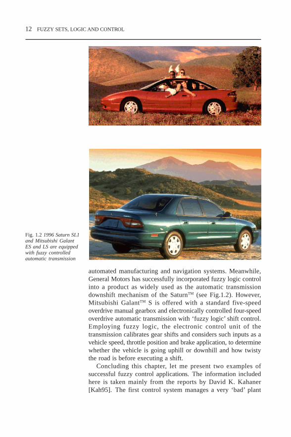
Fig. 1.2 1996 Saturn SL1and Mitsubishi GalantES and LS are equippedwith fuzzy controlledautomatic transmission
automated manufacturing and navigation systems. Meanwhile,General Motors has successfully incorporated fuzzy logic controlinto a product as widely used as the automatic transmissiondownshift mechanism of the SaturnTM (see Fig.1.2). However,Mitsubishi GalantTM S is offered with a standard five-speedoverdrive manual gearbox and electronically controlled four-speedoverdrive automatic transmission with ‘fuzzy logic’ shift control.Employing fuzzy logic, the electronic control unit of thetransmission calibrates gear shifts and considers such inputs as avehicle speed, throttle position and brake application, to determinewhether the vehicle is going uphill or downhill and how twistythe road is before executing a shift.
Concluding this chapter, let me present two examples ofsuccessful fuzzy control applications. The information includedhere is taken mainly from the reports by David K. Kahaner[Kah95]. The first control system manages a very ‘bad’ plant
CHP1.PM5 6/12/97, 1:29 PM12

FUZZY SETS, LOGIC AND CONTROL 13
which is unstable, nonlinear and subject to large disturbances,while the second one is developed to control the object with‘good’ model behaviour.
Table 1.6
Machine systems Human-based Human machinesystems systems
Picture/voice recognition Human reliability model Medical diagnosis
Chinese character Cognitive psychology Inspection datarecognition processing
Thinking/behaviourNatural language models Transfusionunderstanding consultation
Sensory investigationsIntelligent robots Expert systems
Public awareness analysisCrop recognition CAI
Risk managementProcess control CAD
Environmental assessmentProduction management Optimisation planning
Human relations structuresCar/train operation Personnel management
Demand trend modelsSafety/maintenance Development planningsystems Energy analysis
Equipment diagnosticsBreakdown diagnosis Market selection models
Quality evaluationElectrical power Category analysissystem operation Insurance system
Social psychologyFuzzy controller Human interface
Home electrical Management decision-making
appliance controlMultipurpose decision-
Automatic operation making
Knowledge bases
Databases
Example 1.1 Fuzzy controller in an intelligentunmanned helicopterOne of the newest and most challenging technological applicationsis of the fuzzy logic in the control system of a helicopter, whichis fundamentally unstable and with highly nonlinear dynamics.The helicopter Yamaha R-50 is a scaled down (3.6 metres head
CHP1.PM5 6/12/97, 1:29 PM13

14 FUZZY SETS, LOGIC AND CONTROL
to tail) real helicopter with all the machinery for flying, plus allthe control gears but minus the human accommodation. Theengine, with the exhaust pipe, looks like one used in a Yamahamotorcycle. The development of R-50 was completed in 1987.The production number has increased each year from 70 (1990),to 100 (1991), 150 (1992), 200 (1993), and 250 in 1994. Itsapplication is spreading to aerial photography, geographic,geological, oceanographic and coastal surveys, emergency rescueand fire control missions.
Flight demonstration
The demonstration site is about the size of a baseball field. Thehelicopter must fly at a height of about 10 metres. The programconsisted of four parts:
A. Command-based flight: a square path. The vehicle was to‘take off’, do ‘forward flight’, ‘90 degrees righthand turn’, ‘forwardflight’ again, ‘hover and turn left 90 degrees’, ‘fly backwards’,‘hovering’, ‘fly sideways to the left’, ‘hover and then land’.
B. Command-based flight: zigzag. The vehicle was to ‘flyforward’, then ‘fly to the right’, ‘fly to the left’, then again ‘flyto the right’, ‘fly to the left’, and then ‘hover’.
C. GPS (Global Position System) guided flight: from point Ato point B while going through other two points, point #1 andpoint #2. It starts from point A, ‘fly 20 metres forward to point#1’, ‘hover and turn right 90 degrees’, ‘fly 30 metres forward topoint #2’, ‘hover and turn left 90 degrees’ then ‘fly 20 metresforward to point B’.
D. Image-guided flight: auto-landing. The vehicle was to ‘takeoff’, ‘fly forward and search for the landing spot’, ‘tilt down the
Fig. 1.3. An unmannedvoice-controlledhelicopter [Schw92](© IEEE 1992)
CHP1.PM5 6/12/97, 1:29 PM14

FUZZY SETS, LOGIC AND CONTROL 15
camera’, ‘hover and adjust position’, ‘adjust position as thevehicle lowers itself’ and then ‘land on the target spot’.
The flight programs proceeded smoothly without a hitch. Thesignificance of this demonstration, however, is not what it lookslike, but what goes into the control systems and what is involvedin the new technology.
The reasons for applying fuzzy control. It has been over 50years since the helicopter and conventional control technique weredeveloped. The automatic control for the helicopter, however, hasbeen limited to
hovering control; maintaining the height after reaching a stable flight; change of route at intervals in accordance with the determined
route.
Only partial automation has been accomplished. Most of thecontrol has been manually operated.
Although unmanned helicopters, especially for military use,have been developed in every large country of the world, theircontrol techniques have been confined to the remote controlsystem using manual operation; there have been no papers writtenon the semi-remote control system (by language instructionemployed) in this project because the conventional control hasdifficulty in achieving automatic operations.
Fuzzy control in view of the helicopter characteristics
A. Nonlinear behaviour: a helicopter has nonlinear characteristics.Conventional control methods use a linear theory only suitable forlinear systems. In conventional control, the model is designed bya linear approximation around the equilibrium point of thehelicopter, resulting in operational difficulties in states that deviatefar from the equilibrium, and there is no guarantee for theperformance. Fuzzy control is nonlinear and is thus suitable forthe nonlinear system control.
B. Unstable system: the helicopter is intrinsically unstable, andthere is a time delay between the input and output operations. Itis thus difficult to achieve stability by the conventional feedbackcontrol which operates with further time lag.
C. Effect of the environment: a helicopter is very sensitiveto the wind, for example. Exposure to a side wind leads to
CHP1.PM5 6/12/97, 1:29 PM15

16 FUZZY SETS, LOGIC AND CONTROL
instability during hovering. As a pilot redirects the nose of thehelicopter towards the wind, he attains stable hovering. Nowthere are no techniques associated with the conventional controlmethod to deal with the change of the environment. However,fuzzy logic control can realise the pilot’s stabilisation methodby only adding the ‘if–then’ rules to accommodate with theenvironmental changes.
Example 1.2 Fuzzy subway control system(Sendai, Japan) [Yas85]Another example of a major project is automatic train operation,which was installed in the Sendai Subway system, and has beenin operation for approximately ten years. So this is a completeengineering system, not a prototype or experimental system.
A conventional train controller is based on proportional integralderivative (PID) control. The PID controller takes the errorbetween the target speed and the actual train speed to control thetrain’s motor and brake. A conventional control system requiresa linearised system model, a desired state, and an error criterion,which is usually some function of the differences between desiredand actual state. Given these, a PID control system can easily beimplemented. This depends heavily upon analytic representationsof the system and an error function as well as an assumption thatthe linearised model description does not deviate much from thereal state. This method does not provide adequate control forsystems with time-varying parameters or highly nonlinear systems,although often they can be tuned by incorporating detailed designinformation.
Humans can do still better because they can (on the basis ofexperience) evaluate the system objectives. Fuzzy predictivecontrol is closer to a human operation. It attempts to evaluate notonly the current system state, but also assesses the effect of acontrol command on the resulting state. As the performanceindices are taken in human terms, good, very good, etc., this leadsto the need to define the meaning of various linguisticperformance indices.
The fuzzy predictive train controller applies a system modelof the motor and brake to predict the next state of the speed,stopping point and running time (three-state vector) as inputs toa fuzzy controller. The fuzzy controller then selects the mostlikely control command based on the predicted state vector.
In many fuzzy control applications the model of the system
CHP1.PM5 6/12/97, 1:29 PM16

FUZZY SETS, LOGIC AND CONTROL 17
is unknown – it is for this reason that fuzzy control methods areusually chosen. But in this case the model is known precisely andis relatively simple because of the nature of the problem. In thiscase, fuzzy control is more concerned with the subjectivemeasures for riding comfort, running time, and how close the traincomes to a predesignated stopping point. Hence a distinctionmust be made between fuzzy control for unknown systems ornonlinear systems compared with fuzzy control with linguisticmeasures of the main objective.
The train operation is broadly classified into two controlmodes: (1) train speed regulation control, and (2) train stoppingcontrol. In the context of the train operation system, there werethree key purposes:
acceleration to a target speed; deciding and maintaining target speed; stopping accurately at a target position.
Also there are six performance indices:
safety; accurate stopping; running time; energy consumption; comfort; traceability (maintaining target speed).
For the Sendai system, conventional PID automatic train operationcontrol hardware was already being installed. Thus, incorporatingpredictive fuzzy control required only software changes to theonboard minicomputer. The system actually began commercialoperation in 1987, and now operates through 17 stations overabout 15 km. It is highly computerised, including:
train tracking; route control; schedule management and adjustments; public address system (train approach, etc.); data transmission to/from train (trip pattern, etc.); depot in/out control; closed circuit TV in control centre when trains enter station; system monitoring; logging; system supervision (power, disaster prevention, etc.); business management (ticket sales, usage, etc.).
CHP1.PM5 6/12/97, 1:29 PM17

18 FUZZY SETS, LOGIC AND CONTROL
The use of fuzzy technology in automatic control of the SendaiSubway system exhibits several interesting facets:
Fuzzy control is an efficient alternative to conventionalcontrol. Indeed, although automating train-driving operationscan be viewed as simple, and conventional control can alsobe used, it does demonstrate that fuzzy control can do as gooda job as conventional control.
The Sendai Subway fuzzy control seems to have some advan-tages over a conventional control, such as riding comfort forpassengers, savings in labour force and energy consumption,etc.
From a technical viewpoint, it demonstrates that it is possibleto use expert knowledge to design control laws and fuzzytheory as a means to translate natural language information intocontrol strategies.
All your examples were from the engineering field. I am currentlytrying to persuade our business colleagues to utilise fuzzy controlin an internal decision engine application and for fuzzy clustering.Could you provide us with an example of a financial applicationof fuzzy control?
Example 1.3 Financial evaluation and control
One of the most important applications of fuzzy logic wasYamaichi Fuzzy Fund. This is the premier financialapplication for trading systems. It handles 65 industries anda majority of the stocks listed on Nikkei Dow and consistsof approximately 800 fuzzy rules. Rules are determinedmonthly by a group of experts and modified by seniorbusiness analysts as necessary. The system was tested for twoyears, and its performance in terms of the return and growthexceeds the Nikkei Average by over 20 per cent. While intesting, the system recommended ‘sell’ 18 days before BlackMonday in 1987. The system went into commercialoperations in 1988. All financial analysts including Westernanalysts will agree that the rules for trading are all ‘fuzzy’.
Another example, which could be provided, is IBM which inJanuary 1994 announced the first commercial fuzzy informationsystems application: a medical insurance fraud detection system.It demonstrates a high potential of fuzzy logic and controlapplications in ‘non-traditional’ areas.
CHP1.PM5 6/12/97, 1:29 PM18

BASIC MATHEMATICAL CONCEPTS OF FUZZY SETS 19
2 BASIC MATHEMATICALCONCEPTS OF FUZZYSETS
2.1 Fuzzy sets versus crisp sets
You said that fuzzy sets theory had many applications. Why do wecall it fuzzy sets theory?
The theory of sets and the concept of a set itself constitute afoundation of modern mathematics. As far as one considersmathematical and simulation models of application problems, onedeals with mathematics and the set theory at the base ofmathematics. So if one changes this concept the whole buildingof modern science should be altered.
What is ‘fuzzy’ in a fuzzy set? How do you obtain a fuzzy set froma crisp one?
Let us remember how we determine a crisp set: It is a collectionof objects of any kind, numbers, geometric points, chairs, pencils,etc. Usually the set is determined by naming all its members (thelist method) or by specifying some well-defined properties satisfiedby its members (the rule method). In the second method, a ruleallows us to determine whether any particular element of theuniversal set belongs to the set under determination, or it does not.Similarly, one can name the elements of the universal set which donot belong to our set. Then all the other elements of the universalset compose the determined set. To indicate that an individual objectx is a member of a set A, we write x ∈ A. Whenever x is not anelement of a set A, we write x ∉ A.
I understand that we can compose the set from some numbers, e.g.A= 3,4,5,6 by naming them. But how can we name, say, allpositive numbers?
The list method can be used for finite sets only. When youdetermined your set, you actually used the rule method (rule: all
CHP2.PM5 6/13/97, 8:41 AM19

20 BASIC MATHEMATICAL CONCEPTS OF FUZZY SETS
members are positive numbers). And by this rule you define whichelements of the universal set belong to your set.
Fine. I intuitively understand what the set is. But could you givea more mathematical definition, please?
I am sorry, I can’t. As I have already said, the concept of theuniversal set is a basic concept which is difficult to determine. Wecan make analogy with the universe. The universe is everythingaround us. The universal set (sometimes called the universe)contains all possible elements having nature or property underconsideration. If we determine the set of the numbers larger than3, the universe will contain all numbers. If we determine the setof the whole numbers larger than 3, the universe will contain allwhole numbers. If we consider the set of long pencils, the universewill contain the set of all pencils. The number of elements of theuniversal set is always larger than or equal to the number ofelements of the set considered.
Then any set is a subset of the universal set, isn’t it?That’s right! Any set A can be considered as a subset of the
universe U and we can write A ⊂ U. There is another importantset, the empty set ∅. While the universe contains everything, thisset contains nothing, no elements.
You mentioned the set of long pencils. Can a set include not justnumbers?
Yes, it can. The elements of the set can have any nature: wecan have a set of points, a set of houses, a set of students, etc.You need to remember just that the nature of the elements of anyparticular set should coincide with the nature of the universe onwhich it is determined.
If we take the universal set as a base, then we can easilydetermine any particular set (or strictly speaking a subset of theuniversal set) by saying if any element of the universal set doesor does not belong to this set. This process, by which individualsfrom the universal set X are determined to be either members ornon-members of a set, is mapping the universal set into thedetermined set, and as mapping it can be defined by a functionwhich is usually called a characteristic function. For a given setA this function assigns the value µ
A(x) to every x ∈ X. Guess how
many values may this function have?This function determines if the element of the universal set does
or does not belong to this set A. Hence the function may have twovalues: TRUE or FALSE.
CHP2.PM5 6/13/97, 8:41 AM20

BASIC MATHEMATICAL CONCEPTS OF FUZZY SETS 21
Fig. 2.1 Definition of a set
That’s right. If we use Boolean function, we will have TRUE or FALSE, or in numbers,1 or 0.
1 if and only if x ∈ Aµ
A(x) =
0 if and only if x ∉ A
Sometimes this function is called a discrimination function, because it discriminatesthe elements of the universal set which belong to the set from those which do not.Determining the discrimination function, we divide the universal set into two parts. Sowe have the certain discrimination and the certain border between these two parts.
CHP2.PM5 6/13/97, 8:41 AM21

22 BASIC MATHEMATICAL CONCEPTS OF FUZZY SETS
BA
The universe
A B
A A
The universe
A
The universe
A BB
Fig. 2.2 Operations oncrisp sets
This figure illustrates the operations of complement, intersectionand union.
–
––
–
––
–––
Mathematically speaking, the discrimination function is mappingof the area on which it is determined to the two-elements set:
µA : X → 0,1 (2.1)
Table 2.1 Properties of crisp set operations
Involution (A)’ = A
Commutativity A ∪ B = B ∪ AA ∩ B = B ∩ A
Associativity (A ∩ B) ∩ C = A ∩ ( B ∩ C)(A ∪ B) ∪ C = A ∪ ( B ∪ C)
Distributivity A ∪ (B ∩ C) = ( A ∪ B) ∩ ( A ∪ C)A ∩ (B ∪ C) = ( A ∩ B) ∪ ( A ∩ C)
Idempotence A ∪ A = AA ∩ A = A
Absorption A ∩ ( A ∪ B) = AA ∪ ( A ∩ B) = A
Absorption of complement A ∪ ( A ∩ B) = A ∪ BA ∩ ( A ∪ B) = A ∩ B
Absorption by U and ∅ A ∪ U = UA ∩ ∅ = ∅
Identity A ∪ ∅ = AA ∩ U = A
Law of contradiction A ∩ A = ∅Law of excluded middle A ∪ A = UDe Morgan’s laws A ∩ B = A ∪ B
A ∪ B = A ∩ B
You may do some operations with crisp sets. The main operationsare complement A (or A’), union A ∪ B, and intersection A ∩B. Laws for these operations are shown in Table 2.1.
I do not understand how to implement these operations.Let us circle the universal set consisting of all points inside
the bold line in Fig. 2.2.
–
CHP2.PM5 6/13/97, 8:41 AM22

BASIC MATHEMATICAL CONCEPTS OF FUZZY SETS 23
Another example: consider all the students in a class as the universalset. All students younger than 20 are as set A and all male studentsare set B. Then the complement of A or A contains all students olderthan 20 years, and complement B or B contains all female students.
The intersection of A and B includes all male students that areyounger than 20. What about the union?
The union should include all male students and all female studentsyounger than 20. It gives us all students except females older than20. This statement can be obtained from De Morgan’s law.
Is there a more mathematical definition of operations?Let us use the characteristic function. Then the complement of
A or A is determined by the characteristic function µA(u) = 1 –
µA (u). The intersection A ∩ B can be determined with the
characteristic function, for example
µA
∩ B (u) = min (µ
A (u), µ
B(u)).
What do you mean saying ‘for example’, ‘can be determined’?How can it be determined otherwise?
The choice of these operations is arbitrary. The only propertythe intersection operation has to satisfy is to return 1 if botharguments are 1, and to return 0 otherwise. Propose anotherformula to calculate the intersection characteristic function.
I think we can use µA^B
(u) = µA
(u) × µB (u).
Beautiful! Now what property should the union characteristicfunction satisfy?
It has to return 1 if one of the arguments is 1, and 0 otherwise.Well done! The following formulae realises it.
µA∪
B (u) = max (µ
A (u), µ
B (u))
Now let us expand a set of possible values of the characteristicfunction from the two-element set to the continuum set (the setof all real numbers between 0 and 1). Let us suppose that thecharacteristic function may have any value between 0 and 1, notjust 0 and 1. Then we can replace (2.1) with
µA: X → [ 0,1 ]
Mathematically it is very easy. But what does it mean in the real world?It means that now we do not determine exactly whether any
particular element of the universal set belongs or does not belongto the set A. We are saying that an element belongs to the set A
–
––
CHP2.PM5 6/13/97, 8:41 AM23

24 BASIC MATHEMATICAL CONCEPTS OF FUZZY SETS
with the determined membership degree. This degree is assessedby a number between 0 and 1.
I understand, that if for the element x its membership degree is 0it does not belong to the set A, and if it is 1 it does. What willhappen if it is 0.5?
It means we do not know whether this element of the universalset does or does not belong to this set A.
And if it is 0.8?We still do not know exactly, but we think the possibility of
belonging is higher.Actually we fuzzify the border between two parts of the
universal set. We expand the set of possible characteristic functionvalues and get the fuzzy set. In fuzzy set theory the characteristicfunction is usually called the membership function.
But it means that the element can be simultaneously in both parts.How can it come?
If we consider Boolean logic where any variable can have justtwo values: TRUE or FALSE, it is impossible. A classic computerworks according to the rules of this logic. However, any real lifesituation is much richer than this black and white model. A realobject usually contains a lot of grades of a grey colour betweenblack and white. So a real object can be more or less black, white,short, long, young, old, etc.
This approach makes the theory more complicated. Two possiblevalues are replaced with a continuum set of values. Thediscrimination function is replaced with the membership function.Other properties of the sets should be changed as well.
From the computer point of view (if such a point exists) you areright. However, a human intellect has had experience of processingthis information for ages. I would say that this model was moregeneral than the previous one. It is obviously closer to the models,that a human being creates in his/her mind. This approach tends todecrease the gap between natural intellect models produced byhuman experts and artificial intelligence models used by computers.
OK. However, don’t these models have to be followed by morecomplicated algorithms and procedures in solving applicationproblems?
Not always. As we will see later, the trend to use ‘accurate’models for describing real objects and processes often leads to the
CHP2.PM5 6/13/97, 8:41 AM24

BASIC MATHEMATICAL CONCEPTS OF FUZZY SETS 25
sophisticated method application. Using fuzzy models, one cansignificantly simplify models and corresponding procedures. Letus leave it for a while and come back and define the basic termsof fuzzy sets.
Definition 2.1 Fuzzy set
A fuzzy set A in the universal set U is a set of ordered pairsof a generic element u and its membership degree µ
A(u) as
A = (u, µA(u))/ u ∈ U
I see the fuzzy set definition is similar to the crisp set one. Todetermine a crisp set we name all the elements of the universewhich belong to the set A. In a fuzzy set we name all the elementsof the universe and supplement to them a number between 0 and1. This number demonstrates to what degree this generic elementbelongs to the defined fuzzy set. Actually, according to thisdefinition we just add to every element a number, which constitutesthe membership degree of this element.
Actually, a fuzzy set is given by its membership function. Thevalue of this function determines if the element belongs to thefuzzy set and in what degree.
Fig. 2.3 Definition of thefuzzy set
CHP2.PM5 6/13/97, 8:41 AM25

26 BASIC MATHEMATICAL CONCEPTS OF FUZZY SETS
Definition 2.2 Support
The support S(A) of a fuzzy set A is the crisp set of all theelements of the universal set for which membership functionhas non-zero value
S (A) = u ∈ U/ µA( u ) > 0
I see. Only those elements should be considered that have anychance of becoming members of the fuzzy set.
Yes. Depending on the universal set, a fuzzy set can have afinite or an infinite number of elements. The support can be afinite set. It means that just a finite number of elements of theuniversal set have a non-zero membership degree.
Definition 2.3 Crossover point
The element of the universal set, for which the membershipfunction has the value of 0.5, is called a crossover point.
The crossover element marks the point where the possibility ofbelonging becomes lower than the possibility of not belonging.Although an exact position of a crossover point is usually not veryimportant, it characterises a shape of the membership function.
Example 2.1 Consider a set of five pencils located in the box.Determine a fuzzy set of ‘short pencils’ A asA= pencil1/0.2, pencil2/0.5, pencil3/1.0, pencil4/1.0, pencil5/0.9
In this example pencil3 and pencil4 are exactly short, pencil5 isalmost short, pencil2 is more or less short and pencil1 is almostexactly not short.
Example 2.2 If the support is infinite we can consider membershipfunctions in Fig. 2.4.
Fig. 2.4 Membershipfunctions examples
1 2 3 4 5 6 70
0.1
0.2
0.3
0.4
0.5
0.6
0.7
0.8
0.9
1
‘About 3’
a) Membership function ‘about 3’ b) Membership functions for‘short’ and ‘long’ pencils
CHP2.PM5 6/13/97, 8:41 AM26

BASIC MATHEMATICAL CONCEPTS OF FUZZY SETS 27
In this figure we have different shapes of membership functions.You are right. The most often used functions are:
piecewise linear (triangular and trapezoidal); quadratic; gaussian according to the formula µ(x) = exp (– (x – µ)/σ)2); some special functions.
Which one is better to use?Triangular or trapezoidal (piecewise linear) functions have
proved to be more popular with fuzzy logic theoretics andpractitioners rather than higher order based functions such asquadratic, cubic, etc. A possible reason for this is a simplicity ofthis function often allowing for the prediction and calculation ofan output of the fuzzy system. Another reason is that the extrasmoothness introduced by higher order fuzzy sets and demandinghigher computational consumption is not strongly reflected in theoutput quality of a fuzzy model. However, the problem of themembership function choice has not yet been solved theoretically.Different researchers choose numerous shapes in variousapplication problems.
a) quadratic c) Gaussian
b) triangular and trapezoidal d) special function
Fig. 2.5 The most widelyused membershipfunction shapes
CHP2.PM5 6/13/97, 8:41 AM27

28 BASIC MATHEMATICAL CONCEPTS OF FUZZY SETS
A shape determines how many elements of the universal set havethe membership degree larger than a given value between 0 and 1.
Definition 2.4 Level set
The set of elements that belong to the fuzzy set A at least tothe degree α is called the α-level-set or α-cut-set
A α= u ∈ U / µA( u ) > α
This definition gives us another way to determine a fuzzy set.As any membership function has all its values between 0 and 1,we can construct a membership function on the base of the levelsets. And because a membership function determines a fuzzy setcompletely, any fuzzy set A can be considered as the union of allits level sets: A = ∪α Aα, α ∈ [0,1].By the way, what do you think, either an α-level-set is crisp orfuzzy?
As a subset of a fuzzy set, it is fuzzy.I do not agree that it is a subset of a fuzzy set. This is another
set, it contains the elements of the universe, so it is a subset ofthe universe. As it includes just elements without theirmembership degrees, it is crisp.
Example 2.3 The 0.5-level-set in Example 2.1 contains pencil2,pencil3, pencil4, pencil5, the 0.8-level-set contains pencil3,pencil4, pencil5.
Example 2.4 Consider the fuzzy set ‘about 3’ of Example 2.2. The0.15- and 0.45-level-sets are marked on Fig. 2.7.
Fig. 2.6. A fuzzy set as acollection of α-level sets
α
u
µA( u )
CHP2.PM5 6/13/97, 8:41 AM28

BASIC MATHEMATICAL CONCEPTS OF FUZZY SETS 29
Fig. 2.7 α-level-sets
Fig. 2.8 Main terms ofmembership functions
Membership
0 5 10 15 20 250
0.1
0.2
0.3
0.4
0.5
0.6
0.7
0.8
0.9
1 Low
High
Membership degree
Labels
Membership function
Support
Universe of discourse
Height
Definition 2.5 Height of a fuzzy set
The height of a fuzzy set A, hgt(A) is given by a supremum ofthe membership function over all u∈U hgt(A) = sup
U µ
A( u )
(Supremum in this definition means the highest possible (oralmost possible) degree.)
CHP2.PM5 6/13/97, 8:41 AM29

30 BASIC MATHEMATICAL CONCEPTS OF FUZZY SETS
2.2 Operations on fuzzy setsNow let us try to determine operations with fuzzy sets. How dowe do it? Any idea?
Because the fuzzy set is a generalisation of a crisp set, we cangeneralise operations with crisp sets.
How to generalise operations? What do you mean?
I do not know. The word ‘generalisation’ sounds nice andsignificant.I guess that the same operations, that have been determined oncrisp sets, can be determined on fuzzy sets. And because a fuzzyset is determined by its membership function, the operationsactually should operate with membership functions.
Exactly! And main operations are complement, intersection (orconjunction) and union (or disjunction).
Definition 2.6 The complement of a fuzzy set A has amembership function which is pointwise defined for allu ∈ U by µ
A( u ) = 1 – µ
A( u ).
This corresponds to the logical NOT operation. It is quitesimple.
Definition 2.7 The intersection of two fuzzy sets C = A ∩ Bhas the membership functionµ
A
∩
B (u ) = µ
A(u) t µ
B(u) ≤ Min (µ
A(u), µ
B(u) )
where t is a triangular norm (or measure) defined by the nextdefinition.
0 5 10 15 20 25 300
0.1
0.2
0.3
0.4
0.5
0.6
0.7
0.8
0.9
1
length, cm
Short =A
Long = NOT A
Fig. 2.9 Complementoperation on fuzzy sets
CHP2.PM5 6/13/97, 8:41 AM30

BASIC MATHEMATICAL CONCEPTS OF FUZZY SETS 31
Definition 2.8 The t normThe triangular norm is a two-place function from [0,1] * [0,1]to [0,1], i.e. t : [0,1] * [0,1] → [0,1] which is non-decreasingin each element x t w ≤ y t z if x ≤ y, w ≤ z commutative,associative and satisfies boundary conditions x t 0 = 0, and xt 1 = x; for any x,y,z,w ∈ [0,1].
I do not understand this definition. How can we use it? How canwe calculate the membership function of the intersection? Itcannot be applied as an operation definition.
Why not?
A definition should explain how to make an operation. From thisdefinition we do not know what to do with membership functionsin order to obtain a result. Should we add them, multiply or makelogical operations?
One can use different ways and various formulas to calculatethe triangular norm. Some of them are given in Table 2.2.
Table 2.2 Some classes of fuzzy set unions and intersections
Reference Fuzzy unions Fuzzy Intersections Range ofparameter
max (a,b) min (a,b)
a + b – ab ab
Schweizer & 1 – max[0, (1 – a) –p max(0,a–p + b–p –1)–1/p p ∈ (– ∞,∞)Sklar [1961] + (1 + b) –p –1)] 1/p
Hamacher (a + b – (2 – g) ab)/ ab/(g + (1–g)(a + b – ab)) g ∈ (0, ∞ )[1978] (1 – (1 – g)ab)
Frank [1979] 1 – logs [1 + (s1–a – 1) log
s [1 + (sa – 1)(sb – 1)/s – 1] s ∈ (0,∞ )
(s1–b – 1)/s –1]
Yager [1980] min[ 1, (aw + bw)1/w] 1 – min[1,(1 – a)w + w ∈ (0, ∞ )(1 – b)w)1/w]
Dubois & a + b – ab – min(a,b,1 – α)Prade [1980] ab/max(a,b,α) α ∈ (0,1)
max(1 – a,1 – b,α)
Dombi [1982]1 1
λ ∈ (0,∞)1 + [(1/a – 1)–λ + (1/b – 1) –λ]–1/λ 1 + [(1/a – l)λ + (1/b – 1)λ]1/λ
CHP2.PM5 6/13/97, 8:41 AM31

32 BASIC MATHEMATICAL CONCEPTS OF FUZZY SETS
Anyone can propose his or her own definition!?You’re right! It is a good exercise to introduce a new way to
calculate the triangular norm. Try to write down a few.
Can we compare results of these definitions? Maybe different waysof calculation produce different results.
They definitely do (see Fig. 2.10). On this figure, twooperations, min and product, were applied. And you see they haveproduced different results. For example, for the element u = 5, ifwe calculate the t norm operation as a product, the membershipdegree will be 0.15. However, if one calculates it as a minimumthe degree will be 0.35. So, the difference is quite significant.
You see yourself your definition is wrong because it can berealised by different ways which give different results.
Nothing is wrong here. You can use any definition if itsatisfies the conditions of Definition 2.8. We can compare thesedifferent results, e.g. the usual tnorms are intersection andalgebraic product with x ∩ y ≥ x × y. Calculate the other resultsand compare them.
Definition 2.9 The union (or disjunction) of two fuzzy setsC = A ∪ B has the membership functionµ
A ∪
B (u) = µ
A(u) s µ
B(u) ≥ max ( µ
A(u), µ
B(u) )
where s is a triangular co–norm (measure or s norm) definedbelow.
0 5 10 15 20 25 30 35 40 450
0.1
0.2
0.3
0.4
0.5
0.6
0.7
0.8
0.9
1 A B
min (A,B)
A*B
Fig. 2.10. Two differentways for calculating t1–
norm operations
CHP2.PM5 6/13/97, 8:41 AM32

BASIC MATHEMATICAL CONCEPTS OF FUZZY SETS 33
Definition 2.10. The s normThe triangular co-norm is a two-place function from [0,1] *[0,1] into [0,1], i.e. s: [0,1] * [0,1] → [0,1] which is non-decreasing in each element, commutative, associative andsatisfies boundary conditions x s 0 = x, and x s 1 = 1; for x∈ [0,1].
As far as I see, the triangular norm and the co-norm are rathersimilar.
The definitions are similar and they have a determinedrelationship with each other. This relationship is given by theequivalent of De Morgan’s law in set theory:
x s y = 1 – (1 – x) t (1 – y), for x,y ∈ [0,1] (2.2)
Now, by how many ways can the triangular co-norm be calculated?
I would not be surprised if it had plenty of ways.That’s right! Some of them are given in Table 2.2.
Which way is the best to use?I do not know the answer. Different researchers propose and
apply different ways. Even computer packages include differentopportunities, which can be chosen by a user. The most commonlyused are intersection and algebraic product. Few experiments havebeen carried out as to the optimal triangular norm selection. Themin (max) operators, for example, indicate no set interaction,since when one membership function is smaller (larger) withrespect to the other, it has no influence on the resultantmembership function.
Is it good or bad?This robustness is an advantage if the accurate values of
membership functions are not required. However, it makes theresult less sensitive to changes in one of the arguments.
To illustrate the idea of different calculations [Drian93] usesthe example by Van Nauta Lemke. First consider Fig. 2.11,representing a prison cell with two windows. Suppose we havetwo different problems to be solved:
1. How easy is it for a prisoner to escape from his prison cell?2. How easy is it for sunlight to come into a prison cell?
Suppose window 1 is very difficult to escape from (the ‘simplicity’is 0.1) and window 2 is easier (the simplicity is 0.3). Suppose also
CHP2.PM5 6/13/97, 8:41 AM33
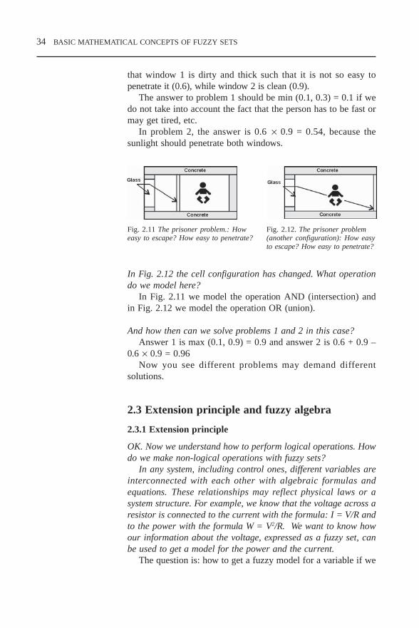
34 BASIC MATHEMATICAL CONCEPTS OF FUZZY SETS
that window 1 is dirty and thick such that it is not so easy topenetrate it (0.6), while window 2 is clean (0.9).
The answer to problem 1 should be min (0.1, 0.3) = 0.1 if wedo not take into account the fact that the person has to be fast ormay get tired, etc.
In problem 2, the answer is 0.6 × 0.9 = 0.54, because thesunlight should penetrate both windows.
In Fig. 2.12 the cell configuration has changed. What operationdo we model here?
In Fig. 2.11 we model the operation AND (intersection) andin Fig. 2.12 we model the operation OR (union).
And how then can we solve problems 1 and 2 in this case?Answer 1 is max (0.1, 0.9) = 0.9 and answer 2 is 0.6 + 0.9 –
0.6 × 0.9 = 0.96Now you see different problems may demand different
solutions.
2.3 Extension principle and fuzzy algebra
2.3.1 Extension principle
OK. Now we understand how to perform logical operations. Howdo we make non-logical operations with fuzzy sets?
In any system, including control ones, different variables areinterconnected with each other with algebraic formulas andequations. These relationships may reflect physical laws or asystem structure. For example, we know that the voltage across aresistor is connected to the current with the formula: I = V/R andto the power with the formula W = V2/R. We want to know howour information about the voltage, expressed as a fuzzy set, canbe used to get a model for the power and the current.
The question is: how to get a fuzzy model for a variable if we
Fig. 2.12. The prisoner problem(another configuration): How easyto escape? How easy to penetrate?
Fig. 2.11 The prisoner problem.: Howeasy to escape? How easy to penetrate?
CHP2.PM5 6/13/97, 8:41 AM34

BASIC MATHEMATICAL CONCEPTS OF FUZZY SETS 35
know the fuzzy model for another variable and the functionalrelationship between them. The answer is the extension principle,one of the fundamentals of fuzzy sets theory.
What do we need this extension principle for?It gives us the rule of how to calculate an output of a fuzzy
system. If we know the structure of the system, containing algebraicand logical blocks, and the system inputs are fuzzy, on the basisof this principle we can determine the outputs of the system.
Definition 2.11 Extension principle 1.
If A is a fuzzy set in the universe U and f is a mapping fromU to the universe Y, y = f(u) then the extension principle allowsus to define a fuzzy set B in Y as
B = f(A) = (y, µB(y))|
y = f(u), u ∈ U
where sup µA(u) if f –1(y) ≠ 0,
µB(y) = u∈f–1(y)
0 if f –1(y) = 0
The reason for such a definition is quite obvious. We shouldexpect the same fuzziness incorporated in the second universe asthere was in the first universe.
I understand that. But why do we apply the supremum operation?Because the function f may map different elements of the
universe U into one element of the universe Y. As a result thiselement may inherit a few membership degrees, hence, we needto determine one and we choose the highest one.
Example 2.5 Let A = –2/0.3, –1/0.4, 0/0.8, 1/1, 2/0.7 and y =f (u) = u2.Then B = 4/0.3, 1/0.4, 0/0.8, 1/1, 4/0.7 = 0/0.8, 1/1, 4/0.7.
It is rather simple when we deal with a single-input-single-output(SISO) system. What will happen if we take a system with a fewinputs, for example, a structure as Fig. 2.13?
Fig. 2.13 Two-input-one-output system structure
input 1
input 2
output 1
CHP2.PM5 6/13/97, 8:42 AM35

36 BASIC MATHEMATICAL CONCEPTS OF FUZZY SETS
In this case we need a more general form of the extensionprinciple.
Definition 2.12 Extension principle 2.
Let X be a Cartesian product of the universes X = U1* U
2 *…
*Ur, and A
1, A
2, … , A
r are fuzzy sets in these universes. f is a
mapping from X to the universe Y where y = f(u1, u
2,… , u
r).
Then the extension principle allows us to define the fuzzy setB in Y as
B = (y, µB(y))|
y = f(u1, u2,. . . , ur), ( u1, u2,. . . , ur) ∈ X
where sup min µA1
(u1) , … , µ
Ar(u
r) if f –1(y) ≠ 0,
µB(y) = ( u
1, u
2,… , u
r) ∈ f –1(y)
0 if f –1(y) = 0
Could you explain in greater detail, how this principle works,please?
Let us first consider just a case of two variables: the sum y =u
1 + u
2. Then we have
µB(y) = sup min µ
A1(u
1), µ
A2(u
2)
y = u1+ u
2
One can avoid considering an inverse operation. It means that forany element y of the universe Y we can take any couple of theelements u
1 of U
1 and u
2 of U
2, the sum of which equals to y and
determine the membership degree as the minimum of thecorresponding degrees. You see that one may have a huge or eveninfinite number of combinations of two numbers with the samesum and one needs to choose the supremum of all minimums.
It is rather difficult to apply. Can we use something simpler?In a case of algebraic operations and some classes of fuzzy
sets, we can apply fuzzy algebra and fuzzy numbers. Fuzzyalgebra is not difficult to learn because:
rules are rather natural and reasonable, fuzzy algebra is a generalisation and an extension of an
ordinary algebra.
Fuzzy arithemetic deals with fuzzy numbers.
CHP2.PM5 6/13/97, 8:42 AM36

BASIC MATHEMATICAL CONCEPTS OF FUZZY SETS 37
2.3.2 Fuzzy numbers
Definition 2.13 Fuzzy number.
If the support of the membership function is a part of the realaxis, the fuzzy set represents a fuzzy number if themembership function is normal and convex.
In control and other physical systems we deal with measured(compared against the measurement scale) inputs and outputs. Onecan use fuzzy numbers to model real system variables. Classicalarithmetic and algebra deal with crisp (ordinary) numbers.
Can you write the membership function for the crisp number,please?Yes. For the number A it will be
1, x = Aµ (x) =
0, x ≠ A
Graphically this membership function can be presented as in Fig. 2.14.
And what about the interval? I mean when we know exactly thatthe value cannot be smaller than A
1 and greater than A
3.
If we have an interval, the membership function can be written as
0, x < A1
µ(x) = 1, A1 ≤ x ≤ A
3
0, x > A3
or graphically as in Fig. 2.15
Now let us consider a general fuzzy number (Fig. 2.16)
Before we start I want to ask about normal and convex fuzzy sets.We applied these words in the definition of a fuzzy number. Whatdo they mean?
1
0 A3
( x )
A1 x
µ1
0 A2
Fig. 2.14. Membership function for acrisp number
Fig. 2.15. Membership function for aninterval
CHP2.PM5 6/13/97, 8:42 AM37

38 BASIC MATHEMATICAL CONCEPTS OF FUZZY SETS
Definition 2.14 Normal fuzzy set.The fuzzy set is normal if max µ(x) = 1.
Definition 2.15 Convex fuzzy setConvex means that any α–cut which is parallel to thehorizontal axis A
α = [a
1 (α), a
3 (α)]
yields the property of nesting, that is if
α’ < α = > a1 (α’) ≤ a
1(α) and a
3 (α’) ≥ a
3 (µα).
Alternatively (see Fig. 2.16), if we represent the α-cut by theinterval Aα asAα = [a1(α), a3(α)] and Aα’ = [a1(α’), a3(α’)]then the condition of convexity implies that if α’ < α = >Aα ⊂ Aα’.
You see that the fuzzy set can be considered as a series of α-cut-sets which are represented by the intervals determined on thereal axis. For the convex normal fuzzy sets these intervals arenested.
And what use is this?It means that we can derive operations on fuzzy numbers based
on operations with intervals. These intervals are called theintervals of confidence.
2.3.3 Arithmetic operations with intervals of confidence
Let me propose a problem: how would you find the resultinginterval for some arithmetic operations with the intervals? Anyidea?
1
0
( x )
x
1
2
a1
a1
a1
a2
a3
a32( )
2( )
1( ) a
3 1( )
µ
α
α
α α α αFig. 2.16 Membershipfunction for a fuzzynumber
CHP2.PM5 6/13/97, 8:42 AM38

BASIC MATHEMATICAL CONCEPTS OF FUZZY SETS 39
Based on the extension principle we should find the interval whichcovers all possible results for all possible combinations of theoperands.
That’s right! Look at the following:
Addition: [a1, a
3] + [b
1, b
3] = [a
1 + b
1, a
3 + b
3]
Subtraction: [a1, a
3] – [b
1, b
3] = [a
1 – b
3, a
3 – b
1]
What is [ – 2,4] + [3,5]?The left boundary will be the sum of the left boundaries of theoperands and the right boundary will equal to the sum of the rightboundaries. So [ – 2,4] + [ 3,5] = [1,9]
Good! And in the case of subtraction?
The left boundary of the result will be a difference between theleft boundary of the first operand and the right boundary of thesecond one and the right boundary will equal the differencebetween the right boundary of the first operand and the leftboundary of the second one.
Very good! Now we are ready to consider multiplication.
Multiplication: [a1, a
3] × [b
1, b
3] = [a
1 × b
1, a
3 × b
3] ? (2.3)
For example [3,5] × [4,6] = [12,30].However, if you consider [3,5] × [– 6, – 4] = [– 18, – 20] you
are not able to say that equation (2.3) is valid. A left boundarycannot be larger than a right one.
In this case, the result will be [– 20, – 18], we need just to swapthe boundaries.
Your resulting interval is very narrow, much narrower than inthe case of all positive operands. It is confusing, isn’t it?Yes, it is.
1
( x )µ
0 x1a b1 b33a 1a b1
+3
a +b3
A BA+B
Fig. 2.17 Addition ofintervals
CHP2.PM5 6/13/97, 8:42 AM39

40 BASIC MATHEMATICAL CONCEPTS OF FUZZY SETS
The equation (2.3) is valid only if a1, b
1 ≥ 0, i.e. both operands
are non-negative.Generally, we should apply the formula
[a1, a
3] × [b
1, b
3] = [min(a
1 × b
1,a
1 × b
3,a
3 × b
1,a
3 × b
3), max
(a1 × b
1,a
1 × b
3,a
3 × b
1,a
3 × b
3)]
which is always right.
Now we can easily determine other operations with the intervals.
Inverse: [a1,a
3]–1 = [min(1/a
1,1/a
3),max(1/a
1,1/a
3)].
Division:[a
1,a
3]/[b
1,b
3] = [min(a
1/b
1,a
1/b
3,a
3/b
1,a
3/b
3), max(a
1/b
1,a
1/b
3,a
3/b
1,a
3/b
3)].
If a fuzzy set is defined over the set of positive real numbersonly (that is we consider just positive operands), the last formulascan be simplified:
[a1,a
3]–1 = [1/a
3,1/a
1]
[a1,a
3]/[b
1,b
3] = [a
1/b
3,a
3/b
1]
If we denote the max operation as ∪ and a min operation as ∩,we can rewrite the formulas given above as
[a1,a
3] × [b
1,b
3] = [a
1× b
1 ∩ a
1 × b
3 ∩ a
3 × b
1 ∩ a
3 × b
3, a
1× b
1
∪ a1 × b
1 ∪ a
1 × b
3 ∪ a
3 × b
1 ∪ a
3 × b
3]
[a1,a
3]–1 = [1/a
1 ∩ 1/a
3, 1/a
1 ∪ 1/a
3]
[a1,a
3] / [b
1,b
3] = [a
1/b
1 ∩ a
1/b
3 ∩ a
3/b
1 ∩ a
3/b
3, a
1/b
1 ∪ a
1/b
3 ∪
a3/b
1 ∪ a
3/b
3]
Why have we replaced one notation with another one?We are trying to prepare for an introduction of operations with
fuzzy numbers.
Fig. 2.18 Multiplicationof intervals
CHP2.PM5 6/13/97, 8:42 AM40

BASIC MATHEMATICAL CONCEPTS OF FUZZY SETS 41
2.3.4 Arithmetic operations with fuzzy numbers
You remember that a fuzzy set A can be considered as a unionof α-cut-sets:
A = ∪ Aα α ∈ [0,1]
The results obtained above for the intervals can be expanded tofuzzy numbers A and B by expressing the fuzzy numbers at eachlevel of α as an interval of confidence.
The following formulas can be derived:
Addition: µ A + B
(z) = ∪ (µA(x) ∩ µ
B(y))
z = x + y
Subtraction: µ A – B
(z) = ∪ (µA(x) ∩ µ
B(y))
z = x – y
Multiplication: µ A × B
(z) = ∪ (µA(x) ∩ µ
B(y))
z = x × y
Division: µ A / B
(z) = ∪ (µA(x) ∩ µ
B(y))
z = x/y
Are these formulas valid for any fuzzy numbers?Yes, they are, including a special case of fuzzy numbers – crisp
or ordinary numbers. One can replace any fuzzy number with anordinary one, giving ordinary arithmetic.
Actually calculation of these formulas requires a lot of work. Howcan I decrease the time necessary for computation?
We can consider some special cases of fuzzy numbers whichare the most commonly used in applications. In these cases, thesituation can be significantly simplified.
1
0
( x )
x1a3
ab1b31a b1
+3
a +b3
A B A + B
µ
Fig. 2.19 Addition offuzzy numbers
CHP2.PM5 6/13/97, 8:42 AM41

42 BASIC MATHEMATICAL CONCEPTS OF FUZZY SETS
Triangular fuzzy numbers
This class of fuzzy numbers has been used extensively in differentapplications, first of all because of its simplicity. The membershipfunction is
0, x < a1
(x – a1) / (a
2 – a
1), a
1 ≤ x ≤ a
2
µ (x) =(a
3 – x) / (a
3 – a
2), a
2 ≤ x ≤ a
3
0, x > a3
If an α–cut is applied to define a fuzzy number then the fuzzynumber can be determined as
∀ α ∈ [0,1]: Aα = [ a1α,a
3α ] = [(a2 – a
1) × α + a
1, –(a
3 – a
2) ×
α + a3]
So a triangular fuzzy number (TFN) can be given by threeordinary numbers (a
1, a
2, a
3).
Arithmetic operations on TFN have the following properties:
Addition or subtraction operations on two TFN result inanother TFN;
Multiplication, inversion and division operations on TFN donot necessarily give a TFN as a result.
Addition: A + B = (a1,a
2,a
3) + (b
1,b
2,b
3) = (a
1+b
1,a
2+b
2,a
3+b
3)
Subtraction: A – B = (a1,a
2,a
3) – (b
1,b
2,b
3) = (a
1–b
3,a
2–b
2,a
3–b
1)
Trapezoidal fuzzy numbers (TrFN)
The membership function is:
0, x < a1
(x – a1) / (a
2 – a
1), a
1 ≤ x ≤ a
2
µ (x) = 1, a2 ≤ x ≤ a
3
(a3 – x) / (a
3 – a
2), a
3 ≤ x ≤ a
4
0, x > a4
1
0 a 3
( x )
a 1 xaa2 4
µ1
0 a 3
( x )
a 1 xa2
µ
Fig. 2.20 Triangular fuzzy number Fig. 2.21 Trapezoidal fuzzy number
CHP2.PM5 6/13/97, 8:42 AM42

BASIC MATHEMATICAL CONCEPTS OF FUZZY SETS 43
A TrFN can be described completely by a quadruplet A =(a
1,a
2,a
3,a
4). It can also be characterised by the interval of
confidence at level α. Thus,
∀ α ∈ [0,1]: Aα = [ a1α ,a
4α ] = [(a2–a
1) × α + a
1, – (a
4–a
3)
× α + a4]
As one can see, a TFN is a particular case of a TrFN with a2 = a
3.
Properties:
addition or subtraction operations on two TrFN give anotherTrFN;
multiplication, inversion and division operations on TrFN donot necessarily give a TrFN.
Addition: A + B = (a1,a
2,a
3,a
4) + (b
1,b
2,b
3,b
4) = (a
1+b
1, a
2+b
2,
a3+b
3, a
4+b
4)
Subtraction: A – B = (a1,a
2,a
3,a
4) – (b
1,b
2,b
3,b
4) = (a
1–b
4, a
2–b
3,
a3–b
2, a
4–b
1)
Gaussian Fuzzy Numbers (GFN)
exp ( – ((x – m)/σ1)2), x ≤ m
µ(x) =exp ( – ((x – m)/σ
2)2), x > m
GFN can be described by a triplet (m, σ1, σ
2 ) where m is the crisp
magnitude of the GFN and σ1
,σ2 are fuzziness parameters (a
membership function is given in Fig. 2.5c).
Arithmetic operations on GFN have the following properties:
Addition or subtraction operations on two GFN give a GFN. Addition: A + B = (m
a, σ
1a, σ
2a) + (m
b, σ
1b, σ
2b) = (m
a+m
b,
σ1a
+σ1b
, σ2a
+σ2b
) Subtraction: A – B = (m
a, σ
1a, σ
2a) – (m
b, σ
1b, σ
2b) = (m
a –
mb, σ
1a+σ
1b, σ
2a+σ
2b)
Multiplication, inversion and division operations do notgenerally produce a GFN.
However, if the fuzziness parameters σ1 and σ
2 are much less than
the magnitudes of the operands, the result can be described as aGFN. In this case one can consider σ
1 = σ
2 and will have for the
multiplication:
A × B = (ma, σ
1a, σ
2a) × (m
b, σ
1b, σ
2b) ≈ ( m
a × m
b, σ
a × abs(m
a)
+ σb × abs(m
b), σ
a × abs(m
a) + σ
b × abs(m
b))
CHP2.PM5 6/13/97, 8:42 AM43

44 BASIC MATHEMATICAL CONCEPTS OF FUZZY SETS
2.4 Linguistic variables and hedgesI have heard that fuzzy logic operates with words and terms ofnatural language and you have been presenting justmathematical formulas.
Fuzzy sets theory operates just with mathematical models asany other mathematical theory does. It replaces one sort ofmathematical model with another one. However, you are right,fuzzy sets theory allows us to model terms of natural languagewith the help of linguistics variables. It has opened a wide areaof use of this theory in control and other applications.
How does it work?A linguistic variable is one with a value that is a natural
language expression referring to some quantity of interest. Thesenatural language expressions are then in turn names for fuzzy setscomposed of the possible numerical values that the quantity ofinterest can assume.
So is the value of the linguistic variable a word?Yes, a word or a word sentence. This is the main difference
between a linguistic variable and a numerical one.
Generally, a linguistic variable is a composite term u = u1, u
2, ....,
un which is a concatenation of atomic terms u
1, u
2, ...,u
n, and
according to [Cox94] these atomic terms can be divided into fourcategories:
primary terms, which are the labels of specified fuzzy subsetsof the universe of discourse (e.g. small and big);
the connectives AND, OR and the negation NOT; hedges such as VERY, MOST, RATHER, SLIGHTLY, MORE
OR LESS, etc.; markers such as parenthesis.
VARIABLE
Linguistic Numerical
words orsentences of a
natural language
numbersValues
CHP2.PM5 6/13/97, 8:42 AM44

BASIC MATHEMATICAL CONCEPTS OF FUZZY SETS 45
A primary term is actually just a name or a label of a fuzzy set.It usually describes the word which is used by experts to expresstheir opinion about the value of one of the object characteristics,e.g old, large, fast, etc.
The connectives realise the operations of intersections, union,complement considered earlier.
Example 2.6 How can we express slow or medium, slow and notfast?
Fig. 2.22 Membershipfunctions for linguisticvalues
0 5 10 15 20 25 300
0.1
0.2
0.3
0.4
0.5
0.6
0.7
0.8
0.9
1 slow fastNOT fast medium
slow OR medium
NOTfast AND medium
Fig. 2.23 Obtainingmembership functions forcomposite terms from themembership functions forprimary terms
CHP2.PM5 6/13/97, 8:42 AM45

46 BASIC MATHEMATICAL CONCEPTS OF FUZZY SETS
Hedges are used to produce a larger set of values for a linguisticvariable from a small collection of primary terms through theprocesses of intensification or concentration, dilation andfuzzification. For example, the operator ‘very’ is usually definedas a concentration operator as very u = u2
This operator can also be composed with itself, thusvery (very u) = (very u) 2 = u 4
Example 2.7 The composite term ‘very old’ can be obtained fromthe term old asvery old = old2 (see Fig. 2.24)
Example 2.8 Consider a fuzzy set of ‘short pencils’ A (Example2.1) asA = pencil1/0.2, pencil2/0.5, pencil3/1.0, pencil4/1.0, pencil5/0.9.Then a fuzzy set of ‘very short pencils’ can be determined asB = pencil1/0.04, pencil2/0.25, pencil3/1.0, pencil4/1.0, pencil5/0.81.
We can see that this operator enhances an action of the term. Itsignificantly changes the membership function shape. Try to findthe inverse hedge, which ‘fuzzifies’ the term and expands thewidth of the corresponding membership function.
Obviously this hedge (let us denote it now as hedg1) can bewritten as hedg1 u = u 1/2
Why do you think so?
Because then we have hedg1 (very u) = hedg1 (u2) = (u2) 1/2 = uproducing the inverse action.
Very good! What we need to do in order to form a linguistichedge is just to find a proper label. What would you like tochoose?
Let us name it ‘more or less’. Then we have more or less (veryu) = u. However, I do not understand why more or less meansexactly u 1/2. Can it be, for example, u 0.4?
Of course it can. You are able to determine the mathematicalmodel for more or less as you wish.
Why do we choose this model?Some psychological experiments have been conducted to
determine the parameters of mathematical models expressinglinguistic hedges. Proposed parameters express an average opinionof an average human expert. It can be varied, of course, within
CHP2.PM5 6/13/97, 8:42 AM46

BASIC MATHEMATICAL CONCEPTS OF FUZZY SETS 47
the borders limited by just a common sense. You need toremember just that a hedge changes a membership degree for anypart in the domain or we can say in the scientific language that ittransforms a fuzzy surface.
A scientific approach features not just a specific language but alsoan attempt to classify objects. Can we classify all possible hedges?
I do not think we can. As hedges could be constructed fromwords and expressions of the natural language and a vocabularyof the natural language is immense we are able to describe a verylimited subset of all possible hedges. And as we discussed earlierevery user could construct the mathematical description for anyhedge which is applied in any model. [Cox94] classified somewidely used hedges (see Table 2.3).
Table 2.3 Some widely used hedges
HEDGE MEANING
about, around, near, roughly approximate a scalarabove, more than restrict a fuzzy regionalmost, definitely, positively contrast intensificationbelow, less than restrict a fuzzy regionvicinity of approximate broadlygenerally, usually contrast diffusionneighbouring, close to approximate narrowlynot negation or complementquite, rather, somewhat dilute a fuzzy regionvery, extremely intensify a fuzzy region
There are different types of hedges in that table. Which one is themost important?
It is not easy to answer that question. Hedges represent thewords of natural language. Which words are more important thanothers? Moreover, this table does not cover all hedges and allwords. We have included just a small subset of hedges and words,maybe the most widely used. For example, approximation hedgesplay an important role because they fuzzify a scalar.
What do you mean? How can we fuzzify a scalar number?I mean that we can obtain the fuzzy domain for the variable.
For example ‘height is about 3 m’ will produce the followingfuzzy set (Fig. 2.25). The role of the approximation hedges is toconvert scalar values into fuzzy values and their place is at thebeginning of the fuzzification process.
CHP2.PM5 6/13/97, 8:42 AM47

48 BASIC MATHEMATICAL CONCEPTS OF FUZZY SETS
Why did you choose this membership function? And generally howdoes an approximation hedge know how wide to make the supportof the fuzzy set?
An important question, especially because the approximationhedges usually begin the process and determine the consequentresults. To choose the width we should consider these results: howdoes the domain of the generated fuzzy region match the domainof the consequent fuzzy space. We have to try to determine thisdomain from our knowledge of the problem or the problemcontext. We should consider not just immediate results but alsoconsequent fuzzy sets which are determined on the base of theinitial ones.
Why do you constantly repeat the phrase ‘consequent results’?Let me explain. If we want to determine the domain for the
fuzzy variable ‘about 5’ and we know that it will be used todetermine the pressure at the testing point 1 and we know the rulethat ‘if the pressure at the testing point 1 is about 5 then thetemperature at the testing point 23 is high’ and we know thedomain for this temperature, then we can consider how differentdomains for the pressure match this known domain for thetemperature.
So we should try the membership function, consider the resultsand try again?
Yes, this is a usual design process, consisting of tries anderrors.
If we already have the fuzzy set, for example ‘the speed shouldbe around average’ (Fig. 2.26) can we apply the approximationhedges here?
Sure we can. We shall fuzzify the previous domain a little bit.
1 2 3 4 5 6 70
‘About 3m’
m
1
0.9
0.8
0.7
0.6
0.5
0.4
0.3
0.2
0.1
0 10 20 30 40 50 60 70 80 900
0.1
0.2
0.3
0.4
0.5
0.6
0.7
0.8
0.9
1
old
very old
Age (years)
Fig. 2.24 Obtaining the membershipfunction for the term ‘very old’ from themembership function for the term ‘old’
Fig. 2.25 Membership function‘about 3 m’
CHP2.PM5 6/13/97, 8:42 AM48

BASIC MATHEMATICAL CONCEPTS OF FUZZY SETS 49
0 5 10 15 20 25 300
0.1
0.2
0.3
0.4
0.5
0.6
0.7
0.8
0.9
1 average
very average
close to, neighbouring average
about, around, near,roughly average
in the vicinity of average
speedFig. 2.26 Applyingdifferent hedges
What do other hedges do?The hedges ‘about’, ‘around’, ‘near’, ‘roughly’ perform the
‘average’ fuzzification of the domain. The hedges like ‘close to’,‘neighbouring’ perform a narrow approximation or fuzzification.However, the hedge ‘in the vicinity of’ expands the initial domainsignificantly (Fig. 2.26). Be careful with this hedge! Its applicationcould result in a fuzzy set with the domain exceeding the generaldomain of the working fuzzy set and could lead to an unforeseendegree of ambiguity.
What else can the hedge perform except fuzzifying the domain ofthe fuzzy set?
A lot of different things. Restrict a fuzzy domain, for example,like hedges ‘above’, ‘more than’, ‘below’, ‘less than’ .
Can we apply these hedges to a scalar? How do we construct amembership function ‘above 5’?
[Cox94] proposes a crisp set where we have the step functionwith the border exactly at the level of 5 . However, if we initiallyapply the approximation hedge and the restriction hedge ‘abovearound 5’, we have the usual membership function. An importantclass of the hedges are those which intensify a fuzzy region(‘very’, ‘extremely’) or dilute it (‘quite’, ‘rather’, ‘somewhat’).The intensification hedges reduce a membership degree for eachvalue of the domain, while the dilution hedges increase it (Fig.2.27).
CHP2.PM5 6/13/97, 8:42 AM49
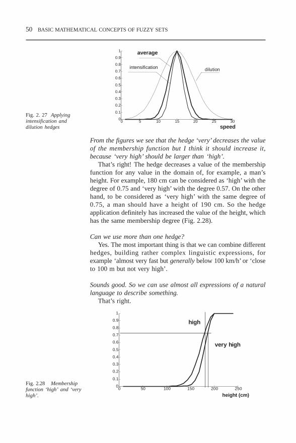
50 BASIC MATHEMATICAL CONCEPTS OF FUZZY SETS
Fig. 2.28 Membershipfunction ‘high’ and ‘veryhigh’.
0 50 100 150 200 2500
0.1
0.2
0.3
0.4
0.5
0.6
0.7
0.8
0.9
1
height (cm)
high
very high
0 5 10 15 20 25 300
0.1
0.2
0.3
0.4
0.5
0.6
0.7
0.8
0.9
1 average
intensification dilution
speed
Fig. 2. 27 Applyingintensification anddilution hedges
From the figures we see that the hedge ‘very’ decreases the valueof the membership function but I think it should increase it,because ‘very high’ should be larger than ‘high’.
That’s right! The hedge decreases a value of the membershipfunction for any value in the domain of, for example, a man’sheight. For example, 180 cm can be considered as ‘high’ with thedegree of 0.75 and ‘very high’ with the degree 0.57. On the otherhand, to be considered as ‘very high’ with the same degree of0.75, a man should have a height of 190 cm. So the hedgeapplication definitely has increased the value of the height, whichhas the same membership degree (Fig. 2.28).
Can we use more than one hedge?Yes. The most important thing is that we can combine different
hedges, building rather complex linguistic expressions, forexample ‘almost very fast but generally below 100 km/h’ or ‘closeto 100 m but not very high’.
Sounds good. So we can use almost all expressions of a naturallanguage to describe something.
That’s right.
CHP2.PM5 6/13/97, 8:42 AM50

BASIC MATHEMATICAL CONCEPTS OF FUZZY SETS 51
But how can a computer understand and process theseexpressions?
Hedges in complex expressions are processed in a manneranalogous to English adjectives. Thus the expression ‘not morethan above zero’ is interpreted as not (more than (about(zero))).Firstly, a fuzzy region ‘about zero’ is created. Note, that it isconstructed by applying the hedge ‘about’ to the crisp number ofzero. The main thing you should remember is that the linguisticvariables and hedges allow us to construct mathematical modelsfor expressions of natural language. These models can be used towrite and process rules and other objects.
2.5 Fuzzy relationsNow, when we know how to determine a fuzzy set and what it is,we are able to consider a relationship between fuzzy sets or thefuzzy relations. The fuzzy relation regards at least two fuzzy sets.
What do we need this fuzzy relation for?We need it to understand and formalise application problems.
Many application problem descriptions include fuzzy relations. Forexample, to describe a plant or a control system one determines,how an output(s) depends on inputs, or the relationship betweenoutputs and inputs. If one constructs a database and an informationsystem, one determines the relations between different attributes.To model a fuzzy system one uses rules like
if speed is slow then pressure should be high
If the speed is denoted as variable A and pressure as variable Bthen one will have in a general case the rule: if A then B
This rule gives the dependence of output B on input A. How dowe determine the output if we know the input?
We must know the relation between these two variables.
Definition 2.16 A fuzzy relation of the form A ⇒ B, R, can bedefined as a relation of two fuzzy sets A ∈ U and B ∈ V asa fuzzy subset on the Cartesian product U *V. R is characterisedby the bivariate membership function µ
R (u, v) as
R = A * B = ∫ U*V
µ R
(u, v) / (u,v)
or for finite sets:
R = A * B = Σ u,v
µ R
(u, v) / (u,v) (2.4)
CHP2.PM5 6/13/97, 8:42 AM51

52 BASIC MATHEMATICAL CONCEPTS OF FUZZY SETS
This is very difficult for non-mathematical people to understand.What should we integrate?
Actually we do not integrate anything in a sense of amathematical operation.
What does the ∫ sign mean then?It shows that all possible combinations of all the elements of
both universes of discourse should be considered. It is easier toexplain when both universes are finite sets. Suppose we have twofinite fuzzy sets: A which is given by its membership function µ
A
= (1/1, 0.8/2, 0.6/3, 0.5/4, 0.4/5, 0.2/6), and B with themembership function µ
B = (0.5/5, 1/6, 0.3/7). Now we should
consider all the combinations of the elements of the universeswhere the membership function has non-zero values. How manycombinations do we have here?
The first fuzzy set has 6 non-zero elements and the second one has3. Then the fuzzy relation has 6 × 3 = 18 elements. Here are thesecombinations: (1,5), (1,6), (1,7), (2,5), (2,6), (2,7), (3,5), (3,6),(3,7), (4,5), (4,6), (4,7), (5,5), (5,6), (5,7), (6,5), (6,6), (6,7).
That’s right! And now we need to determine a membershipdegree for every pair.
How?Just use the definition! You can use either the minimum or
product. If we use the minimum we have
µR (u,v) = 0.5/ (1,5), 1/(1,6), 0.3/(1,7), 0.5/(2,5), 0.8/(2,6), 0.3/
(2,7), 0.5/(3,5), 0.6/(3,6), 0.3/(3,7), 0.5/(4,5), 0.5/(4,6), 0.3/(4,7),0.4/(5,5), 0.4/(5,6), 0.3/(5,7), 0.2/(6,5), 0.2/(6,6), 0.2/(6,7).
And what will happen if we use the product?µ
R (u,v) = 0.5/(1,5), 1/(1,6), 0.3/(1,7), 0.4/(2,5), 0.8/(2,6), 0.24/
(2,7), 0.3/(3,5), 0.6/(3,6), 0.18/(3,7), 0.25/(4,5), 0.5/(4,6), 0.15/(4,7), 0.2/(5,5), 0.4/(5,6), 0.12/(5,7), 0.1/(6,5), 0.2/(6,6), 0.06/(6,7)
We have different answers!Again different problems can demand different solutions! And
in the case of continuous membership functions, we use the sign∫ to show ‘integration’ of all possible combinations.
Hang on! The fuzzy relation is the same fuzzy set but determinedon the universe which is a combination of two other universes.
Absolutely! To denote this new universe we use the words‘Cartesian product’ to demonstrate that we formed a new support set.
CHP2.PM5 6/13/97, 8:42 AM52

BASIC MATHEMATICAL CONCEPTS OF FUZZY SETS 53
Why did we use just the minimum and product operations? Canwe use other operations from Table 2.2?
Sure we can! More accurately we should have determined theequation (2.4) as a t norm operation.
µR (u,v) = ∫
u,v µ
A (u) t µ
B ( v) / (u,v)
or µ
R (u,v) = Σ
u,v µ
A (u) t µ
B ( v) / (u,v).
To choose which one to use, let us compare their actions. You canconsider different applications described in the literature (see, forexample, [Har93]). Even for simple illustrative examples, it canbe observed that an algebraic product operator leads to a smootherfuzzy relation surface.
Now let us try to make some calculations of fuzzy relations.
Definition 2.17 N-ary fuzzy relationSimilarly to (2.4), we can determine the n-ary relation betweenn fuzzy sets.
R U
1 * U
2 *... * U
n = ∫
U1 * ...*U
n µ
R (u
1, … , u
n ) / (u
1, … , u
n ) ∈
U1 * … * U
n
or in the case of discrete sets
R U
1 * U
2 *... * U
n = Σ
U1
* ...*Un µ
R (u
1, … , u
n ) / (u
1, … , u
n ) ∈
U1 * … * U
n
where u1 ∈ U
1, u
2 ∈ U
2, … , u
n ∈ U
n.
You see that this relation is determined on the n-dimensional spaceU
1 * … * U
n.
This is very difficult to understand! What does n-ary fuzzyrelationship mean? How can I imagine it?
To imagine it you should have a multidimensional space vision.
How do you calculate its result?Actually you need to calculate the membership function of
this relation as a Cartesian product. To do it you may use any tnorm. Let us determine the Cartesian product of the fuzzy sets.
CHP2.PM5 6/13/97, 8:42 AM53

54 BASIC MATHEMATICAL CONCEPTS OF FUZZY SETS
Definition 2.18 Cartesian productIf A
1, … , A
n are fuzzy sets in the universes of discourse U
1,
… , Un then the Cartesian product of A
1, … , A
n is a fuzzy
set in the product space U1 * … * U
n with the membership
function
µ A
1* . . . *A
n ( u
1, … , u
n ) = µ
A1 (u
1) t µ
A2 (u
2) t … t µ
An (u
n)
What do we need it for? I guess a simple two–dimensional fuzzyrelation is more than enough.
With a two-dimensional relation you can derive the output ofone simple rule: if A then B, e.g., if speed is slow then temperatureis low. However, a fuzzy rule can consist of fuzzy sets from morethan two disparate universes of discourse: if A then B then C, e.g.,if speed is slow then temperature is low then pressure is high. Inthis case we should apply a n-ary relation. You have to rememberthat all the fuzzy sets here vary in nature and are determined inthe different universal sets.
What will happen if we have a few rules? for example, iftemperature is low then pressure is high, or, if temperature ismedium then pressure is medium, or, if temperature is high thenpressure is low.
A good question! Of course, in practical problems we usuallyhave a few rules. To calculate the result we should combine allthe rules. Mathematically every rule is described by a relation.All the rules will be described by the composition of theserelations.
Definition 2.19 Multirelational compositionIf R and S are fuzzy relations in the Cartesian spaces U * Vand V * W respectively, the composition of R and S is a fuzzyrelation given by the sup – t composition
µR ° S
= [ sup V ( µ
R (u,v) t µ
S (v, w)), u ∈ U, v ∈ V, w ∈ W
or by the inf-s composition
µR ° S
= [ inf V ( µ
R (u,v) s µ
S (v, w)), u ∈ U, v ∈ V, w ∈ W.
I do not understand which formula to apply. We have got two ofthem.
If you look carefully you will see that we have more than twobecause s and t operations can be determined by different ways.
CHP2.PM5 6/13/97, 8:42 AM54

BASIC MATHEMATICAL CONCEPTS OF FUZZY SETS 55
Your explanation has not made the situation easier. All the possiblecombinations are not used in practical applications, are they?
In practice the sup-min, sup-algebraic and if-max compositionoperators are utilised. And to make the situation easier you canshow yourself, that sup-min and if-max operations produce thesame result.
We can provide some properties of the sup-min composition:
(R ∪ T) ° S = R ° S ∪ T ° Sif R
1 ∈ R
2 then R
1 ° S ∈ R
2 ° S
(R ∩ T) ° S ∈ (R ° S) ∩ (T ° S)for R
1, R
2, R, T ∈ U * V, and S ∈ V * W
In practice, the most important case of compositional inferenceis when we know the fuzzy input and the fuzzy relation betweenthe input and the output and we need to obtain the output.
Definition 2.20 Compositional rule of inferenceIf R is a fuzzy relation in U * V and ΑΑΑΑΑ is a fuzzy set in Uthen the fuzzy set B in V induced by ΑΑΑΑΑ is given by
ΑΑΑΑΑ ° R for sup–t compositionB =
ΑΑΑΑΑ ° R for inf–s composition
You see that because the fuzzy relation is actually the fuzzy set,we can determine the operations with fuzzy relations similarly aswith fuzzy sets.
Definition 2.21 If R and S are fuzzy relations in U * V the intersection of Rand S is
µR∩S
(u,v) = µR(u,v) t µ
S(u,v)
where t-norm can be calculated as a minimum operator, forexample
µR∩S
(u,v) = min ( µR(u,v), µ
S(u,v))
or a product µR∩S
(u,v) = µR(u,v) × µ
S(u,v)
–
––
–
–
CHP2.PM5 6/13/97, 8:42 AM55

56 BASIC MATHEMATICAL CONCEPTS OF FUZZY SETS
Definition 2.22If R and S are fuzzy relations in U * V the union of R and S is
µR ∪ S
(u,v) = µR
(u,v) s µS (u,v)
where we can calculate s norm as a maximum operator, forexample,
µR ∪ S
(u,v) = max ( µR(u,v), µ
S(u,v)).
And what do we need these definitions for?A fuzzy relation describes interactions between fuzzy variables.
For example, if we have the statement ‘Temperature 1 is aboutTemperature 2’,we actually have two fuzzy variables: Temperature1 and Temperature 2. By this statement we wish to describe therelation between them. Suppose Temperature 1 can have fivevalues, 11, 12,13, 14, 15, and Temperature 2 can have threevalues, 10, 12, 14. Then the fuzzy relation can have themembership function:
µ R*S
(u,v) = (0.9/(10,11), 0.7/(10,12), 0.5/(10,13), 0.3/(10,14),0.1/(10,15), 0.9/(12,11), 1/(12,12), 0.9/(12,13), 0.7/(12,14), 0.4/(12,15), 0.5/(14,11), 0.7/(14,12), 0.9/(14,13), 1/(14,14), 0.9/(14,15))
or if we rewrite it in a more convenient table (matrix) form:
Temperature 1
11 12 13 14 15
Temperature 10 1.0 0.7 0.5 0.3 0.1
2 12 1.0 1.0 1.0 0.7 0.4
14 0.5 0.7 1.0 1.0 1.0
Consider now another statement: ‘Temperature 1 seems to belarger than Temperature 2’. This fuzzy relation will have themembership function:
Temperature 1
11 12 13 14 15
Temperature 10 0.9 1.0 1.0 1.0 1.0
2 12 0.1 0.5 0.9 1.0 1.0
14 0 0 0.1 0.5 0.9
Now we want to determine the membership function for thestatement ‘Temperature 1 is about Temperature 2 and Temperature
CHP2.PM5 6/13/97, 8:42 AM56

BASIC MATHEMATICAL CONCEPTS OF FUZZY SETS 57
1 seems to be larger than Temperature 2.’ This relation can bedetermined as an intersection of two relations and will have themembership function:
Temperature 1
11 12 13 14 15
Temperature 10 1.0 0.7 0.5 0.3 0.1
2 12 0.1 0.5 0.9 0.7 0.4
14 0 0 0.1 0.5 0.9
Try to determine the membership function for the statement‘Temperature 1 is about Temperature 2 or Temperature 1 seemsto be larger than Temperature 2.’
I understand this relation to be determined as a union of both andwill have the membership function:
Temperature 1
11 12 13 14 15
Temperature 10 0.9 1.0 1.0 1.0 1.0
2 12 1.0 1.0 1.0 1.0 1.0
14 0.5 0.7 1.0 1.0 1.0
The definitions and examples considered above allow us to obtainthe fuzzy output of the fuzzy system block and to understand thebasics of fuzzy reasoning methods.
CHP2.PM5 6/13/97, 8:42 AM57

58 BASIC MATHEMATICAL CONCEPTS OF FUZZY SETS
CHP2.PM5 6/13/97, 8:42 AM58

THE STRUCTURE AND OPERATION OF A FUZZY CONTROLLER 59
3 THE STRUCTURE ANDOPERATION OF AFUZZY CONTROLLER
3.1 The reasons to apply fuzzy controllersDuring our study we have learned many techniques for thesynthesis of automatic controllers. Why do we need to learn onemore?
The proposed method differs significantly from conventionalones. Usually a control strategy and a controller itself issynthesised on the base of mathematical models of the object orprocess under control. The models of an object under controlinvolve quantitative, numeric calculations and commonly areconstructed in advance, before realisation.
What about adaptive or self-organising controllers?In these controllers, the exact control strategy is not calculated
in advance but is generated by optimisation algorithms based onthe controller ‘experience’. However, this approach also supposesthe construction of ‘numeric’ mathematical models.
Isn’t there another approach?Yes, there is. A different method is to comprehend instructions
and to generate strategies based on a priori verbal communication.Most control engineers would accept intuitively that mathematicalmodelling, which they perform in translating their concept of acontrol strategy into an automatic controller, is completelydifferent from their own approach to a manual performance of thesame task. On the other hand, linguistic description of controlseems to be similar to its manual implementation.
I do not understand the reason for this. I guess if we apply a rightmethod it should produce the best results (in some sense). I thinkpeople just apply the wrong numeric models.
I agree with you just partly. The problem is that often it is verydifficult to derive the ‘right’ model. Many real objects and real
CHP3.PM5 6/13/97, 10:21 AM59

60 THE STRUCTURE AND OPERATION OF A FUZZY CONTROLLER
life processes are too complicated to model mathematically.Instead, if we try to construct a good model, it may be toocomplex for a successful application of a control theory. In Fig.3.1 you may see that there is a long way to go to solve a controlproblem. Unfortunately, one meets a lot of disturbances on theway. Usually even the best model is not complicated enough fora comprehensive description of a real process. On the other hand,it may be too complex to apply.
Why fuzzy control?
Ability to translate imprecise/vague knowledge of human experts Simple, easy to implement technology Software design and hardware implementation support Results are easy to transfer from product to product Smooth controller behaviour Robust controller behaviour Ability to control unstable systems
Maybe you are right. However, to investigate the problem, weconstructed a mathematical model. How can we control the objectotherwise?
It was Mamdani who demonstrated the way [Proc79] byconstructing the first fuzzy controller. The controller was designedfor a plant which comprised a steam engine and boilercombination. The model of the plant had two inputs: the heat inputto the boiler and the throttle opening at the input of the enginecylinder, and two outputs: the steam pressure in the boiler and thespeed of the engine. The problem in classical control was that theplant model was highly nonlinear with both magnitude andpolarity of the input variables.
Fig. 3.1 Control problem-solving process structure
CHP3.PM5 6/13/97, 10:21 AM60

THE STRUCTURE AND OPERATION OF A FUZZY CONTROLLER 61
FUZZY LOGIC EXPLOITS THE TOLERANCE FOR IMPRECISION
High precision entails high cost ⇒ to minimise cost, minimiseprecision
High precision entails low solvability ⇒ to make a problem treatable,lower precision
I know it is not easy to control such a plant.Yes, this plant possesses different characteristics at different
operating points, so that the direct digital controller implementedfor comparison purposes had to be tuned (by a trial and errorprocess) to reach the best performance each time the operatingpoint was altered.
3.2 Fuzzy rules processing
3.2.1 Mamdani-type fuzzy processing
Mamdani proposed to control the plant by realising some fuzzyrules or fuzzy conditional statements, for example:
if pressure error (PE) is Negative Big (NB)then heat change (HC) is Positive Big (PB)
So we can measure outputs of a plant and calculate a controlaction according to this rules table.
What is the pressure error?It is the difference between the current value of the pressure
and the set point. And the speed error (SE) is again the differencebetween the current speed and the set point.
I am not a control engineer, could you explain what the set pointis?
A set point is usually a desired value for the plant output: thevalues which some measured parameters of the process or theobject should have at a particular time.
It is similar to our boat control, isn’t it?Exactly! But Mamdani proposed a modification. In order to
improve the control quality, he increased the number of controlinputs and used the change in pressure error (CPE), defined as thedifference between the present PE and the last one (correspondingto a last sampling instant), and the change in speed error (CSE)as well.
CHP3.PM5 6/13/97, 10:21 AM61

62 THE STRUCTURE AND OPERATION OF A FUZZY CONTROLLER
Why does that improve the control quality?Because it provides a controller with some degree of
prediction. For example, if PE is Negative Big and CPE is alsoNegative Big, it means that at the next moment PE will becomeeven more Negative Big and HC should obviously be Positive Big.But if PE is Negative Big and CPE is Positive Big, it means thatat the next moment PE will become Negative Smaller and weshould think about how to choose PE. This addition increases thesensitivity of the controller.
Mamdani realised his controller on the PDP-8 computer. Itcontained 24 rules. A fixed digital controller was alsoimplemented on the computer and applied to the same plant fora comparison. For the fixed controller, many runs were requiredto tune the controller for the best performance. This tuning wasdone by a trial-and-error process. The quality of the fuzzycontroller was found to be better than the best result of the fixedcontroller each time, so opening a new era in a controller design.
I do not understand why it was so important. I have heard therule-based control was used before Mamdani.
True. But the main problem is how to process these rules.Mamdani used fuzzy theory to calculate the output according tothe rules set and gained a solid theoretical base. It means that wecan use this result to construct other fuzzy controllers. Some ofthese controllers, illustrating different possible applications, aregiven in Table 3.1.
Table 3.1 Fuzzy logic controllers (sample)
Date Application Designers1975 Laboratory steam engine Mamdani and Assilian1976 Warm water plant Kickert and Van Nauta Lemke1977 Ship course control Van Amerongen1978 Rolling steel mill Tong1979 Iron ore sinter plant Rutherford1980 Cement kiln control Umbers and King1985 Aircraft landing control Larkin1989 Autonomous guided vehicle Harris et al.1991 Ship yaw control Sutton and Jess
How are these rules processed?In the literature, the process is called the inference mechanism
or the inference engine. Let us write Mamdani rules in a generalcase. Mathematically a rule will look like
Ri: IF Ai1 (x
1), A
i2 (x
2), ..., A
im (x
m) THEN Y is B
i.
CHP3.PM5 6/13/97, 10:21 AM62
THE STRUCTURE AND OPERATION OF A FUZZY CONTROLLER 63
What does it mean?Here x
1, x
2, ... x
m stand for input variables, for example,
pressure, temperature, error, etc., Aij (xj) (j = 1,2,...m) is a fuzzy
set on Xj, Y is an output variable, B
i is a fuzzy set on Y.
so, in the rule:
if pressure error (PE) is Negative Big (NB) then heat change(HC) is Positive Big (PB)
pressure error is X1,
heat change is Y, Ai1 (x
1) is Negative Big, and
Bi is Positive Big.Right! The method is clear and easy to understand.
I understand it, but what about a computer? It is a computer thatshould calculate the result of this rule.
The result is fuzzy, a fuzzy set. The inputs of the inferenceengine are fuzzy sets and the output is also a fuzzy set. To clarifyhow a computer works in greater detail, let me provide you witha more formalised explanation. We will reintroduce some of thebasic notions dealing with linguistic variables and properties offuzzy sets.
3.2.2 Linguistic variables
A linguistic variable is defined by < Xi, LXi, Xi, A(Xi) >. HereXi is the symbolic name of a linguistic variable (for example,pressure or temperature), LXi stands for the set of linguisticvalues that Xi can take on (Negative Big, Positive Big andZero). The set of all possible values is LX. We denote anarbitrary element of LX by LXi. Xi is the actual physical domainover which the meaning of the linguistic value (temperaturebetween –50 and +100°C) is determined, X can be discrete orcontinuous. A(Xi) is a semantic function which gives a‘meaning’ (interpretation) of a linguistic value in terms of thequantitative elements of X, i.e.,
A(X): LXi → µ LX
(x),
where A(X) is a denotation for a fuzzy set or a membershipfunction defined over X, i.e.,
A(X)= Σ µLX
(x) / x in a case of discrete X,A(X) = ∫ µ
LX (x) / x in a case of continuous X.
CHP3.PM5 6/13/97, 10:21 AM63

64 THE STRUCTURE AND OPERATION OF A FUZZY CONTROLLER
Fuzzy rules
Most of the fuzzy logic applications involve constructionand processing of fuzzy rules
Fuzzy rules serve to describe, in linguistic terms, aqualitative relationship between two or more variables
Processing of fuzzy rules or fuzzy reasoning provides amechanism for using fuzzy rules to compute the response toa given fuzzy controller input
In other words, A(X) is a function which takes a symbol as itsargument and returns the ‘meaning’ of this symbol in terms of thefuzzy set or the membership function of the fuzzy set.
You have not started your explanation, but I’m already lost. Whatis A(X)?
A(X) is a procedure which communicates the membershipfunction for the linguistic value, for example, Negative Big forpressure (Fig. 3.2).
We can now define a set of m rules as
if X1 is LX
1(k) and ... and X
n is LX
n(k) then u is LU(k), k = 1, ..., m,
for example.
if pressure is high and temperature is low then time is short or
Fig. 3.2 A membershipfunction
CHP3.PM5 6/13/97, 10:21 AM64
THE STRUCTURE AND OPERATION OF A FUZZY CONTROLLER 65
if interest rate is low and price is low invest a large amount ofmoney.
In a real engineering fuzzy system usually crisp inputs are used.
3.2.3 Fuzzy rules firing
What do you mean by crisp inputs?I mean that we usually know the value of the inputs:
temperature is 25°C , pressure is 2.5kPa, interest rate is 9.9%. Onecan apply these inputs to the fuzzy system (controller). Thisprocess of applying the inputs to the rules is called firing the rules.Actually, firing consists of computing the degree of matchbetween the crisp input and the fuzzy sets, describing the meaningof the antecedent part of the rules, and then ‘clipping’ the fuzzyset describing the meaning of the consequent part of the rule, tothe degree to which the antecedent part has been matched by thecrisp input.
Could you explain it in greater detail, please? First of all, whatare the antecedent and consequent parts?
The antecedent part is the condition part, the first part of therule. The consequent part is the result part, the second part of therule. For example, in the rule:
if interest rate is low < antecedent part >and share price is low
then invest a large < consequent part >amount of money
When we apply the crisp input to the rule we compare theinput value with the membership functions describing differentlinguistic variables (Fig. 3.3). The result of this comparison willbe a set of pairs (LX, µ
LX (x) ), e.g., if one applies the membership
functions in Fig. 3.3 and the crisp value for the pressure error is–22kPa, then it will be transformed into the fuzzy input (NegativeBig, 0.75) and (Negative Small, 0.05).
I understand that the fuzzy input is the result of comparing thecrisp input and the membership functions assigned to describe thisinput. Where do these membership functions come from?
We will discuss that later in section 4.4. Moving on, the fuzzyinput obtained is applied to the rules.
CHP3.PM5 6/13/97, 10:21 AM65

66 THE STRUCTURE AND OPERATION OF A FUZZY CONTROLLER
Which rules? All of them or just one?One tries to apply or fire all the rules. However, just those rules
where the antecedent parts contain the corresponding input, willbe fired.
Example 3.1 In the following rules table
if pressure is Neg Big then time is short ♣ – firedif pressure is Neg Small then time is short ♣ – firedif pressure is Zero then time is averageif pressure is Pos Small then time is longif pressure is Pos Big then time is long
just first two will be fired in the situation of Fig. 3.3.
Why just these two?Because to fire the rule, one compares the fuzzy input with the
rule antecedent part. If the antecedent part contains this input, therule is fired. Our input is Neg Small and Neg Big, so just the firsttwo rules are fired.
What does one fire the rules for?As a result of firing, the fuzzy input is mapped into the fuzzy
output. To execute this mapping, one needs to transform themembership degree from the rule antecedent part to the ruleconsequent part. In our example, the output will be (short, 0.75),(short, 0.05).
Why two short?Because that is the consequent part of two fired rules.
Fig. 3.3 Fuzzificationof the crisp input –pressure
CHP3.PM5 6/13/97, 10:21 AM66

THE STRUCTURE AND OPERATION OF A FUZZY CONTROLLER 67
Fig. 3.4 Fuzzy processing with the rules table
I think we should choose one result or calculate it.Right! As a result an s -norm is usually calculated and a maximum
operation is taken. So the fuzzy output will be (short, 0.75).
Yes, I realise what happens if we have just one condition in theantecedent part. How do we fuzzify inputs if we have two or more?
Let us again consider the rule
if pressure is Neg Big and temperature is high then time is short
and the corresponding membership functions for pressure (Fig.3.3) and temperature (Fig. 3.5). In the case when crisp inputs arepressure = –22kPa and temperature = 22°C try to fuzzify inputs.
3.2.4 Calculating the applicability degree
At this stage the degree to which the whole condition part (all theinputs) satisfies the rule is calculated. This degree is called the degreeof applicability of the condition part. It is denoted here as β.
β = A1 (x
1) t A
2 (x
2) t ... t A
n (x
n) (3.1)
Fig. 3.5 Fuzzificationof the crisp input –temperature
CHP3.PM5 6/13/97, 10:21 AM67

68 THE STRUCTURE AND OPERATION OF A FUZZY CONTROLLER
where xi is the value for the ith crisp input, Ai (x
i) is the
membership function for the corresponding linguistic value for thecorresponding input, t denotes a t norm operation.
I hope you remember that t norm can be calculated by differentways. So the Equation (3.1) can be rewritten as a product β = A
1
(x1) * A
2 (x
2) * ... * A
n (x
n) or minimum operation
β = min ( A1 (x
1) , A
2 (x
2) , . . . , A
n (x
n))
Hang on! I understand how the t norm can be calculated but Ido not understand what corresponds to what in your explanation.
In our example we have two conditions in the antecedent partand two inputs: pressure and temperature. The membershipfunctions for the linguistic variable pressure are given in Fig. 3.3and the membership functions for the linguistic variabletemperature are given in Fig. 3.5. Now we need to determine thedegree to which the value of –22kPa for pressure matches themembership function for the linguistic value NegBig (it will be0.75) and determine the degree to which the value of 22°C fortemperature matches the membership function for the linguisticvalue high (it will be 0.6). Is it clear?
Yes.Then the degree of applicability can be calculated as
β = 0.6 * 0.8 = 0.48 orβ = min (0.6, 0.8) = 0.6
And now this degree can be applied to the output of the rule.Right! The membership function of the linguistic value for the
consequent part is clipped or scaled to the level of the degree ofapplicability.
3.2.5 Clipping and scaling a fuzzy output
How can the fuzzy set be ‘clipped’?
0 5 10 15 20 250
0.1
0.2
0.3
0.4
0.5
0.6
0.7
0.8
0.9
1 Short Medium
time
Fig. 3.6 Membership function forthe rule consequent part
Fig. 3.7 Scaled and clippedmembership function
CHP3.PM5 6/13/97, 10:22 AM68

THE STRUCTURE AND OPERATION OF A FUZZY CONTROLLER 69
This process is illustrated in Fig. 3.7. Let us denote the ‘clipped’fuzzy set as CLU. The height of CLU(k) is equal to the degreeof match of the kth rule antecedent degree of applicability, andis denoted by βk. The peak value of CLU(k) is equal βk. Actuallyhere we cut the membership function of the unclipped versionLU(k) on the level βk. In our example we need to clip themembership function of the linguistic value short for the outputtime on the level of 0.48 or 0.6 .
How do you scale the fuzzy set?You need to remember that even when we discuss clipping and
scaling fuzzy sets, we actually talk about their membershipfunctions. So I reformulate your question as: how do you scalethe membership function? This method can be applied if you thinkclipping is not fair enough.
Not fair enough?Yes. In the case of clipping, one assigns the same degree to
a range of the input values regardless of the membershipdegrees of the unclipped membership functions. In the case ofscaling, you change the membership degrees for all theelements of the universe. A scale rate depends on anapplicability degree. A scaled membership function shouldhave the peak value equal to the applicability degree. It meansthat in order to produce the scaled membership function, weneed to multiply all the membership degrees by the value ofβ. It is only valid in a case when a peak value of the unclippedfuzzy set was 1. If it was α, then the multiplication factorshould be β/a.
What will one have as a result of a rule application?Each rule produces the clipped or scaled fuzzy set, or more
exactly, the clipped or scaled membership function.
This is not a result of fuzzy processing, is it?What do you think?
I guess it cannot be the result, because until now we havediscussed just processing one rule and usually we have at leasta few.
Right! A fuzzy system includes some rules. Each rule producesthe fuzzy set. To obtain the result of the whole set of rulesprocessing or the fuzzy output of the system, one needs tocombine the resulting fuzzy sets from all the rules.
CHP3.PM5 6/13/97, 10:22 AM69
70 THE STRUCTURE AND OPERATION OF A FUZZY CONTROLLER
I know we may determine the final result as the union of all therules results
U = U1 ∪ U
2 ∪ . . . ∪ U
m
where Ui is the result of applying the ith rule and m is a number
of rules applied.That’s it! Finally, the overall control output U is obtained as
the union of the clipped or scaled control outputs. U may be aconvex fuzzy set or may be a non-convex fuzzy set which consistsof a number of convex fuzzy subsets. You should remember thatU
i is a clipped fuzzy set CLU
i or a scaled fuzzy set SLU
i. Do you
remember how to calculate the union?
There are different ways. For example the maximum operation canbe used
µU = max (µ
U1, µ
U2, … µ
Um)
or one can apply any other s-norm operation.
3.2.6 Sugeno-type fuzzy processing
We have considered how fuzzy processing was realised byMamdani, and the method is called after him. Another methodwas proposed by Sugeno, who changed a part of the rules. In hismethod, the consequent part is just a mathematical function of theinput variables. The format of the rule is:
if A1(x
1), A
2(x
2), . . . , A
n (x
n) then Y = f (x
1, x
2, . . . , x
n).
You see that an antecedent part is similar to the Mamdani method.The function f in a consequent is usually a simple mathematicalfunction, linear or quadratic:
f = a0 + a
1 × x
1 + a
2 × x
2 + . . . + a
n × x
n
The antecedent part in this case is processed in exactly the sameway as the Mamdani method, and then an obtained degree ofapplicability is assigned to the value of Y calculated as thefunction of real inputs.
Can you give an example.Let us again consider the rule:
if pressure is NegBig and temperature is high then time is shortbut now replace it with:
CHP3.PM5 6/13/97, 10:22 AM70

THE STRUCTURE AND OPERATION OF A FUZZY CONTROLLER 71
Fig. 3.8 Fuzzy inferencestructure
CHP3.PM5 6/13/97, 10:22 AM71

72 THE STRUCTURE AND OPERATION OF A FUZZY CONTROLLER
if pressure is NegBig and temperature is high then time is 0.3 ×pressure + 0.5 × temperature.
What do the values of 0.3 and 0.5 mean?Suppose they are factors expressing how the necessary time
depends on pressure and temperature. Then again for crisp inputsof –22kPa for a pressure error and 22°C for temperature wecalculate the applicability degree of this rule, which is 0.6. Nowwe calculate the value for Y as a real function of crisp inputs. Theresult is 0.3 × (–22) + 0.5 × 22 = 4.4. And the membership degreeobtained earlier is assigned to this result. So the output of theinference process will be (4.4, 0.6) where 4.4 is a real result and0.6 is its membership degree.
Is it the final result?No, it is not. It is the result of the application of one rule. The
final result will be obtained after applying all the rules. Then onewill have a fuzzy set as a result. Once again if any element of theuniverse has two or more different membership degrees as a resultof different rules processing, one can choose the maximum valueor apply another s norm calculation method.
Table 3.3 Mamdani verses Sugeno
Similarity:The antecedent parts of the rules are the same.
Difference:The consequent parts are fuzzy sets. The consequent parts are
singletons (single spikes)or mathematical functions ofthem.
Advantages:Easily understandable by a human More effectiveexpert. computationally.Simpler to formulate rules. More convenient in
mathematical analysis and insystem analysis.
Proposed earlier and commonly used. Guarantees continuity ofthe output surface.
Every time we meet different methods for almost any operation. Iunderstand the advantage of making my own choice, but how canI choose the best one? And how should I decide whether to applya Mamdani or Sugeno controller?
I think that the Mamdani fuzzy controller (each rule output isdescribed by a membership function) is good for capturing the
CHP3.PM5 6/13/97, 10:22 AM72

THE STRUCTURE AND OPERATION OF A FUZZY CONTROLLER 73
expertise of a human operator. But it is awkward to design if youhave the plant model but don’t have a working controller (forinstance, a human operator). Sugeno fuzzy controller (each rule’soutput is a linear equation) is good for embedding linear controllerand continuous switching between these output equations. (In fact,gain scheduling!). This becomes very effective when the plantmodel is known. Also an adaptive capability and mathematicaltractability make this type of fuzzy controller a primary choicefor nonlinear and/or adaptive control design that is subject torigorous analysis.
To summarise our discussion about fuzzy inference, we shouldsay that this procedure can be roughly divided into three steps:
Calculation of the degree of applicability of the antecedent(condition) part of each control rule.
Calculation of the inference result (solution fuzzy set) for eachcontrol rule.
Synthesis of the solution set for each control rule into the fuzzyoutput set.
This process is illustrated on Fig. 3.8.
I think fuzzy inference is very complicated. It contains too manyoperations and not one of them is easy to understand. Most ofthese operations are nonlinear mappings.
Maybe you are right. However, this complication allows us tocreate complicated input/output characteristics with a very smallnumber of control rules. The designer should formulate a smallnumber of simple rules, the computer should perform rathercomplicated calculations. Isn’t that fair enough?
3.3 Fuzzy controller operationThe inference engine is the heart of a fuzzy controller (and anyfuzzy rules system) operation. Its actual operation can be dividedinto three steps (Fig. 3.9):
Fuzzification – actual inputs are fuzzified and fuzzy inputs areobtained.
Fuzzy processing – processing fuzzy inputs according to therules set and producing fuzzy outputs.
Defuzzification – producing a crisp real value for a fuzzyoutput.
CHP3.PM5 6/13/97, 10:22 AM73

74 THE STRUCTURE AND OPERATION OF A FUZZY CONTROLLER
FUZZIFICATION
actualinputs
fuzzyinputs
FUZZY PROCESSING
fuzzyoutput
DEFUZZIFICATIONcontroloutput
Inputsmembership
functions
Outputsmembership
functions
Fuzzyrules
if pressure is Neg Big then time is shortif pressure is Neg Small then time is shortif pressure is Zero then time is averageif pressure is Pos Small then time is longif pressure is Pos Big then time is long
Fig. 3.9 Operation of afuzzy controller
We have considered the first two stages. What do we need the thirdone for?
In a real control system, the controller output should be usedto control a real object or process. So we need to know a crispvalue for every output signal. Defuzzification produces this valueon the basis of output membership functions.
Oh! We have spent a lot of time studying this fuzzy inference inorder to come back to the crisp output. What did we need thisfuzzy stuff for?
The main reason is that fuzzy control gives us a rather simpleto use method for producing high quality controllers withcomplicated input/output characteristics.
Can you describe this defuzzification process.Yes, it is not very difficult. But once again a few methods have
been developed and to help you to solve the choice problem, weconsider this process later in Section 4.6 in greater detail.
3.4 Structure of a simple open-loop fuzzy controllerAfter you have considered how a fuzzy controller operates, wecan discuss how to design simple fuzzy controllers.
I understand that in order to construct a fuzzy controller, oneneeds just to write some rules.
It’s not so simple! The classical design scheme contains thefollowing steps:
1. Define the input and control variables – determine whichstates of the process shall be observed and which controlactions are to be considered.
2. Define the condition interface – fix the way in whichobservations of the process are expressed as fuzzy sets.
CHP3.PM5 6/13/97, 10:22 AM74
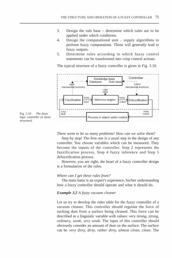
THE STRUCTURE AND OPERATION OF A FUZZY CONTROLLER 75
3. Design the rule base – determine which rules are to beapplied under which conditions.
4. Design the computational unit – supply algorithms toperform fuzzy computations. Those will generally lead tofuzzy outputs.
5. Determine rules according to which fuzzy controlstatements can be transformed into crisp control actions.
The typical structure of a fuzzy controller is given in Fig. 3.10.
There seem to be so many problems! How can we solve them?Step by step! The first one is a usual step in the design of any
controller. You choose variables which can be measured. Theybecome the inputs of the controller. Step 2 represents thefuzzification process, Step 4 fuzzy inference and Step 5defuzzification process.
However, you are right, the heart of a fuzzy controller designis a formulation of the rules.
Where can I get these rules from?The main basis is an expert’s experience, his/her understanding
how a fuzzy controller should operate and what it should do.
Example 3.2 A fuzzy vacuum cleaner
Let us try to develop the rules table for the fuzzy controller of avacuum cleaner. This controller should regulate the force ofsucking dust from a surface being cleaned. This force can bedescribed as a linguistic variable with values: very strong, strong,ordinary, weak, very weak. The input of this controller shouldobviously consider an amount of dust on the surface. The surfacecan be very dirty, dirty, rather dirty, almost clean, clean. The
Fig. 3.10 The fuzzylogic controller (a basicstructure)
CHP3.PM5 6/13/97, 10:22 AM75

76 THE STRUCTURE AND OPERATION OF A FUZZY CONTROLLER
controller can change the force depending on how dirty thesurface is. One can propose the following set of rules to describethe controller operation:
if surface is very dirty then force is very strong,if surface is dirty then force is strong,if surface is rather dirty then force is ordinary,if surface is almost clean then force is weak,if surface is clean then force is very weak.
It is more convenient to write this rules set in a table form.
Table 3.3 Rules table for a fuzzy vacuum cleaner
Surface Forcevery dirty very strong
dirty strongrather dirty ordinary
almost clean weakclean very weak
Will this controller work?It will, however, maybe not very well. To improve the
performance, one should apply some extra expert’s knowledge. Soperhaps a driving force should depend not only on an amount ofdust, but on the surface texture and fabric also. There is somedifference in cleaning wood and wool, for example. So let usintroduce another input: surface type with linguistic values ofwood, tatami, carpet. Then we can implement the following rulestable.
Table 3.4 Rules table for surface type and dust amount
clean almost rather dirty veryclean dirty dirty
wood very weak very weak weak ordinary strong
tatami very weak weak ordinary strong very strong
carpet weak ordinary ordinary strong very strong
Could this controller now be used?Actually a controller like this has been applied in a Japanese
manufactured vacuum cleaner [Hir93]. A block diagram of thecontroller is given in Fig. 3.11. You see that the fuzzy controllerhas two inputs and one output.
CHP3.PM5 6/13/97, 10:22 AM76

THE STRUCTURE AND OPERATION OF A FUZZY CONTROLLER 77
I do not understand how this controller can work in a case of,say, a linen fabric surface. Can it be applied for cleaning wood,tatami and carpets only?
These names, or linguistic labels, have a symbolic sense only.They just mark different membership functions which shoulddescribe how easy it is to clean a particular surface, i.e. to marka different degree of ‘easyness’. And remember these degrees arefuzzy, in that a fabric can be considered as ‘a little tatami andmainly wood’.
And what about linen?This could be placed between tatami and carpet and considered
as a little of this and a little of that.
How is this vacuum cleaner implemented practically?The dust sensor includes a photo transistor which is mounted
opposite an infrared light-emitting diode. Infrared rays are emittedin a beam. When they pass through the dust, some rays are lost,causing the amount which reaches the photo transistor to decrease.The varying component is amplified and used to evaluate theamount of dust on the surface being cleaned.
What about the second input? How is the surface type evaluated?As cleaning proceeds, the amount of dust decreases, but the
speed of decreasing depends on the surface type. If the surfaceis smooth like wood, it is cleaned very fast because it is easy topick up dust from such a surface. On the other hand, it is hard toclean wool carpet surfaces. Thus, by evaluation of the change ofthe dust amount collected during a time unit, we can judge the
Dust sensor
Time counter
Surface typeindicator
Amplifier
Fuzzycontroller
Fan motor
Drive circuit
Fig. 3.11 The structureof the vacuum cleanerfuzzy controller
CHP3.PM5 6/13/97, 10:22 AM77

78 THE STRUCTURE AND OPERATION OF A FUZZY CONTROLLER
type of the surface being cleaned. This controller works wellunder different conditions.
So in this controller, the first input is the amount of dust collectedduring a time unit. And the second input is the change in thisamount. Is that right?
Yes, it is.
Then the second input can be considered as a derivative of thefirst one. Is that right?
Yes, it is.
So our fuzzy controller is an analogy to a classical PD-controller,isn’t it?
Yes, you are right.
3.5 Structure of a feedback PID-like fuzzy controller
3.5.1 Fuzzy controllers as a part of a feedback system
We were taught how to design conventional PID controllers. Howcan I design a fuzzy PID controller?
It is not easy to design an exact PID controller and I think itis not necessary, but one can construct a PID-like fuzzy controller.To do it we need to choose the input and output variables and therules of the controller properly.
If one has made a choice of designing a P-, PD-, PI- or PID-like fuzzy controller, this already implies the choice of processstate and control output variables, as well as the content of therule-antecedent and the rule-consequent parts for each rule.
The process state variables representing the contents of therule-antecedent (if-part of a rule) are selected among:
error signal, denoted by e; change-of-error, denoted by ∆e; sum-of-errors or an integral error, denoted by Σe.
The control output (process input) variables representing thecontents of the rule-consequent (then-part of the rule) are selectedamong:
change-of-control output, denoted by ∆u; control output, denoted by u.
Hang on! What is this error?The error is the difference between the desired output of the objector process under control or the set-point and the actual output.
CHP3.PM5 6/13/97, 10:22 AM78

THE STRUCTURE AND OPERATION OF A FUZZY CONTROLLER 79
This is one of the basic milestones in conventional feedbackcontrol. Furthermore, by analogy with a conventional controller,we have:
e(t) = ysp
– y(t); ∆e (t) = e(t) – e(t – 1); ∆u (t) = u(t) – u(t – 1).
In the above expressions, ysp
stands for the desired processoutput or the set-point, y is the process output variable (controlvariable); k determines the current time.
By the way, considering the classes of a PID-controller, whattype of a controller can be represented by the boat controllerdesigned in the introduction?
I think the deviation can be considered as an error and the turnas a control output. Then this table represents a choice of thecontrol output roughly proportional to the error. It means that wehave designed a P-like controller.
That’s right! Now let us try to design the PD-like controller.
3.5.2 PD-like fuzzy controller
The equation giving a conventional PD-controller is
u(k) = KP
× e(t) + KD × ∆e(t),
where KP and K
D are the proportional and the differential gain
factors.
If I try to describe this equation with the help of rules, whatinputs and outputs should I use for the rules table?I do not know.
Let us consider this equation. The PD controller for any pairof the values of error (e) and change-of-error (∆e) calculates thecontrol signal (u). The fuzzy controller should do the same thing.For any pair of error and change-of-error, it should work out the
Fig. 3.12 A block-diagram of a PD-likefuzzy control system
CHP3.PM5 6/13/97, 10:22 AM79

80 THE STRUCTURE AND OPERATION OF A FUZZY CONTROLLER
control signal. Then a PD-like fuzzy controller consists of rules,and a symbolic description of each rule is given as
if e(t) is <property symbol> and ∆e(t) is <property symbol>then u(t) is <property symbol>, where <property symbol> is thesymbolic name of a linguistic value.
The natural language equivalent of the above symbolic descriptionreads as follows. For each sampling time. t:
if the value of error is <linguistic value> and the value of change-of-error is <linguistic value> then the value of control output is<linguistic value>.
We will omit the explicit reference to sampling time t, since sucha rule expresses a casual relationship between the process state andcontrol output variables, which holds for any sampling time t.
What does the symbolic name of a linguistic value mean?This is one of the linguistic qualifiers, determined for the
proper variable: error, change-of-error or control signal, forexample: high, low, medium, etc.
So I have to have membership functions, describing all thesequalifiers for all my variables: error, change-of-error or control.
Definitely. And you should remember that these variables maybe measured in different units. So the rules of the PD controllercan be like:
if error is Positive Big and change-of-error is Negative Big thencontrol is Negative Small
Why do you use positive and negative values?We need to describe an error signal. Because the actual process
output y can be higher than the desired one as well as lower, theerror can be negative as well as positive. Values of error (e) witha negative sign mean that the current process output y(t) has avalue below the set-point y
sp since e(t) = y
sp – y(t) < 0. A negative
value describes the magnitude of the difference ysp
– y. On theother hand, linguistic values of e with a positive sign mean thatthe current value of y is above the set-point. The magnitude ofsuch a positive value is the magnitude of the difference y
sp – y.
The change-of-error (∆e) with a negative sign means that thecurrent process output y(t) has increased when compared with itsprevious value y(t–1), since ∆e(t) = e(t) – e(t – 1) = –y(t) + y(t –1) < 0. The magnitude of this negative value is given by the
CHP3.PM5 6/13/97, 10:22 AM80

THE STRUCTURE AND OPERATION OF A FUZZY CONTROLLER 81
magnitude of this increase. Linguistic values of ∆e(t) with apositive sign mean that y(t) has decreased its value whencompared to y(t – 1). The magnitude of this value is the magnitudeof the decrease.
Linguistic values of e with a negative sign mean that thecurrent process output y has a value below the set-point y
sp since
e(t) = ysp
– y(t) < 0. The magnitude of a negative value describesthe magnitude of the difference y
sp – y. On the other hand,
linguistic values of e with a positive sign mean that the currentvalue of y is above the set-point. The magnitude of such a positivevalue is the magnitude of the difference y
sp – y.
Linguistic values of ∆e with a negative sign mean that thecurrent process output y(t) has increased when compared with itsprevious value y(t – 1) since ∆e(t) = – (y(t) – y(t – 1)) < 0. Themagnitude of such a negative value is given by the magnitude ofthis increase. Linguistic values of ∆e(t) with a positive sign meanthat y(t) has decreased its value when compared to y(t – 1). Themagnitude of such a value is the magnitude of the decrease.
A linguistic value of ‘zero’ for e means that the current processoutput is about the set-point. A ‘zero’ for ∆e means that thecurrent process output has not changed significantly from itsprevious value, i.e. – (y(t) – y(t – 1)) = 0. The sign and themagnitude for u constitutes the value of the control signal.
3.5.3 Rules table notation
I want to propose to you a convenient form to write down rules. Thistable form is suitable when we have two inputs and one output. Onthe top side of the table we should write the possible linguistic valuesfor the change-of-error (∆e) and on the left side, the error (e). Thecell of the table at the intersection of the row and the column willcontain the linguistic value for the output corresponding to the valueof the first input written at the beginning of the row and to the valueof the second input written on the top of the column.
Let us consider the example [Drian93] where both inputs andan output have a set of possible linguistic values NB, NM, NS,Z, PS, PM, PB where NB stands for Negative Big, NM standsfor Negative Medium, NS stands for Negative Small, Z standsfor Zero, PS stands for Positive Small, PM stands for PositiveMedium and PB stands for Positive Big (Table 3.7).
The cell defined by the intersection of the first row and the firstcolumn represents a rule such as:
if e(t) is NB and ∆e(t) is NB then u(t) is NB
CHP3.PM5 6/13/97, 10:22 AM81

82 THE STRUCTURE AND OPERATION OF A FUZZY CONTROLLER
Table 3.5
PB PM PS Z NS NM NB
PB NB NB NB NB NM NS ZPM NB NB NB NM NS Z PSPS NB NB NM NS Z PS PMZ NB NM NS Z PS PM PBNS NM NS Z PS PM PB PBNM NS Z PS PM PB PB PBNB Z PS PM PB PB PB PB
How do we fill in this table?This table includes 49 rules. We are taking into account now
not just the error but the change-of-error as well. It allows todescribe the dynamics of the controller. To explain how this rulesset works and how to choose the rules, let us divide the set of allrules into the following five groups:
Group 0: In this group of rules both e and ∆e are (positive ornegative) small or zero. This means that the current value of theprocess output variable y has deviated from the desired level (theset-point) but is still close to it. Because of this closeness the controlsignal should be zero or small in magnitude and is intended tocorrect small deviations from the set-point. Therefore, the rules inthis group are related to the steady-state behaviour of the process.The change-of-error, when it is Negative Small or Positive Small,shifts the output to negative or positive region, because in this case,for example, when e(t) and ∆e(t) are both Negative Small the erroris already negative and, due to the negative change-of-error, tendsto become more negative. To prevent this trend, one needs toincrease the magnitude of the control output.
Group 1: For this group of rules e(t) is Positive Big orMedium which implies that y(t) is significantly above the set-point. At the same time since ∆e(t) is negative, this means that yis moving towards the set-point. The control signal is intended toeither speed up or slow down the approach to the set-point. Forexample, if y(t) is much below the set-point (e(t) is Positive Big)and it is moving towards the set-point with a small step (∆e(t) isNegative Small) then the magnitude of this step has to besignificantly increased (u(t) is Negative Medium). However, wheny(t) is still much below the set-point (e(t) is Positive Big) but itis moving towards the set-point very fast (∆e(t) is Negative Big)no control action can be recommended because the error will becompensated due to the current trend.
Group 2: For this group of rules y(t) is either close to the set-
Gr. 0Gr. 1Gr. 2Gr. 3Gr. 4
∆∆∆∆∆ee
CHP3.PM5 6/13/97, 10:23 AM82

THE STRUCTURE AND OPERATION OF A FUZZY CONTROLLER 83
point (e(t) is Positive Small, Zero, Negative Small) orsignificantly above it (Negative Medium, Negative Big). At thesame time, since ∆e(t) is negative, y(t) is moving away from theset-point. The control here is intended to reverse this trend andmake y(t), instead of moving away from the set-point, startmoving towards it. So here the main reason for the control actionchoice is not just the current error but the trend in its change.
Group 3: For this group of rules e(t) is Negative Medium orBig, which means that y(t) is significantly below the set-point. Atthe same time, since ∆e(t) is positive, y(t) is moving towards theset-point. The control is intended to either speed up or slow downthe approach to the set-point. For example, if y(t) is much abovethe set-point (e(t) is Negative Big) and it is moving towards theset-point with a somewhat large step (∆e(t) is Positive Medium),then the magnitude of this step has to be only slightly enlarged(u(t) is Negative Small)
Group 4: The situation here is similar to the Group 2 in somesense. For this group of rules e(t) is either close to the set-point(Positive Small, Zero, Negative Small) or significantly above it(Positive Medium, Positive Big). At the same time since ∆e(t) ispositive y(t) is moving away from the set-point. This control signalis intended to reverse this trend and make y(t) instead of movingaway from the set-point start moving towards it.
So to design a PD-like controller we need just to create a rulestable like Table 3.5.
Not always. The contents of the table can be different. Forexample, you may replace the rule:
if e is PS and ∆e is PM then u is NB
with the rule:
if e is PS and ∆e is PM then u is NM.
We will discuss the concrete choice of the rules in greater detailin Section 4.5.
3.5.4 PI-like fuzzy controller
The equation giving a conventional PI-controller is
u(t) = KP
× e(t) + KI × ∫ e(t) dt, (3.2)
where KP and K
I are the proportional and the integral gain
coefficients. A block diagram for a fuzzy control system looks likeFig. 3.13.
CHP3.PM5 6/13/97, 10:23 AM83

84 THE STRUCTURE AND OPERATION OF A FUZZY CONTROLLER
Fuzzycontroller
PlantOutputControl
Error
Integralof error
Set-pointK
K
+
∫
(Ref.input)
_
i
p
Fig. 3.13 A block-diagram of a PI fuzzycontrol system (version 1)
I see this diagram has a different form from the previous one. Wehave replaced differentiation with integration and a change-of-error with an integral error. How do we formulate the rules table?
Now the fuzzy controller and the rules table have other inputs.It means that the rules themselves should be reformulated.Sometimes it is difficult to formulate rules depending on anintegral error, because it may have the very wide universe ofdiscourse.
What can we do in this case?We can move the integration from the part preceding to a fuzzy
controller to the part following it. We can integrate the output ofa controller, not the input. Then we may have the error and thechange of error inputs and still realise the PI-control.
How does it work?When the derivative, with respect to time, of the Equation (3.2)
is taken, it is transformed into an equivalent expression
du(t) / dt = KP × de(t)/dt + K
I × e(t)
or in the discrete form
∆u(t) = KP
× ∆e(t) + KI × e(t)
One can see here that one has the error and the change-of-errorinputs and one needs just to integrate the output of a controller. Onemay consider the controller output not as a control signal, but as achange in the control signal. The block diagram for this system isgiven in Fig. 3.14. You should remember, that the gain factor Ki isused with the error input and Kp with the change-of-error.
Can you propose the rule format for this controller?We can write the rule as:
if e is <property symbol> and ∆e is <property symbol>then ∆u is <property symbol>.
In this case, to obtain the value of the control output variable u(t),
CHP3.PM5 6/13/97, 10:23 AM84

THE STRUCTURE AND OPERATION OF A FUZZY CONTROLLER 85
the change-of-control output ∆u(t) is added to u(t – 1). It isnecessary to stress here that this takes place outside the PI-likefuzzy controller, and is not reflected in the rules themselves.
Now try to compile the rules table for this type of a controller.
Can we use the table similar to the previous one?Yes, you can. But you should remember that now the output
is not a control signal but the change-of-control.I’m not going to use the same table, let me change something.
Table 3.5
PB PM PS Z NS NM NBPB NB NB NB NB NM NS ZPM NB NB NB NM NS Z PSPS NB NB NM NS Z PS PMZ NB NM NM Z PM PM PBNS NM NS Z PS PM PB PBNM NS Z PS PM PB PB PBNB Z PS PM PB PB PB PB
We have changed two rules:
if e is Z and ∆e is NS then ∆u is PMand if e is Z and ∆e is PS then ∆u is NM.
Will our controller become better?Your correction will lead to the change of the control surface.
Your controller will become more reactive in the neighbourhoodof the set-point. It means that even small deviation errors will befollowed by larger control signals. It is difficult to say if it willbecome better in a general case. However, usually a designer triesto make the control surface smoother in the vicinity of a set-point.So I do not think your modifications have been very successful.
OK. If we want to make our controller less reactive to the largeerrors, what should we do?
Positive large or negative large?
Fuzzy
controller PlantOutputControl
Error
Changeof error
Set-point
Delay ∆t
K
K
-+
+ ∫
Changeof control
p
i
-
Fig. 3.14 A block-diagram of a PI fuzzycontrol system (version 2)
e∆∆∆∆∆e
CHP3.PM5 6/13/97, 10:23 AM85

86 THE STRUCTURE AND OPERATION OF A FUZZY CONTROLLER
Both.In this case you need to modify the top and the bottom rows,
maybe like this:
Table 3.6
PB PM PS Z NS NM NBPB NB NB NB NM NS Z ZPM NB NB NB NM NS Z PSPS NB NB NM NS Z PS PMZ NB NM NS Z PS PM PBNS NM NS Z PS PM PB PBNM NS Z PS PM PB PB PBNB Z Z PS PM PB PB PB
If it is not enough, can we change these rows more significantly?You can do whatever you want. However, if I change the left
bottom corner to PS, for example, there will be a gap between twoadjacent cells. So when e is changed a little bit from PM to PB,the output will jump from NS to PS. Generally speaking youshould avoid these gaps and try to perform a smoothtransformation between adjacent cells (see Section 4.5 for details).
It means that if we want to make significant modifications, it isbest to make changes to the regions than to changes in individualcells.
You are absolutely right!
3.5.5 PID-like fuzzy controller
The equation for a PID-controller is as follows:
u = Kp × e + K
d × e + K
i × ∫ edt.
Thus, in the discrete case of a PID-like fuzzy controller one hasan additional process state variable, namely sum-of-errors, denotedσe and computed as:
σe(t) = .
Have a look at the rules for PD- and PI-like fuzzy controllers andtry to write down the rules format for a PID-like controller.
The symbolic expression for a rule of a PID-like fuzzycontroller is:
if e is < property symbol > and ∆e is < property symbol > and
e∆∆∆∆∆e
CHP3.PM5 6/13/97, 10:23 AM86

THE STRUCTURE AND OPERATION OF A FUZZY CONTROLLER 87
σe is < property symbol> then u is < property symbol >
Good! What is the main difference between the rules for thesecontrollers?
The last one has three conditions in the antecedent part butthe previous ones had just two. So we will need to formulate manymore rules to describe the PID-controller.
Why?
If any input is described with seven linguistic values, as it wasbefore, then because the PID-controller has three inputs and anyrule has three conditions we will need 7 × 7 × 7 = 343 rules.Previously we had just 7 × 7 = 49 rules.
It is too much work to write 343 rules. The PID-like fuzzycontroller can be constructed as a parallel structure of a PD-likefuzzy controller and a PI-like fuzzy controller (Fig. 3.15) with theoutput approximated as:
u = (Kp/2 × e + Kd × de/dt) + (Kp/2 × e + Ki × ∫ edt).
Should we always use these inputs? An error and a change oferror?
Of course not. When information about the object or processunder control and its structure is available, one may not want tobe confined to using error, change of error, and sum of errors asprocess state variables, but rather use the actual process statevariables. The symbolic expression for a rule in the case ofmultiple inputs and a single output (MISO) system is as follows:
if x1 is <property symbol> and ... and x
n is <property symbol>
then u is <property symbol>
Rules of this if – then type are usually derived from a fuzzyprocess model.
Fig. 3.15 The structurefor a PID-like fuzzycontroller
CHP3.PM5 6/13/97, 10:23 AM87

88 THE STRUCTURE AND OPERATION OF A FUZZY CONTROLLER
Example 3.3 The fuzzy controller for steam turbines [Kiup94]
The fuzzy controller has been designed to control the turbinespeed and pressure. The block diagram of a fuzzy control systemfor a turbine speed control is given in Fig 3.16.
All blocks on this figure demonstrate a nonlinear behaviour,which is the main reason for a fuzzy control application. Thefuzzy controller has been designed as a PID-like fuzzy controller.It has three inputs: the error (the difference between a set-pointand an actual output), the change of error, and the integral-error,and one output. To fuzzify the inputs, three classes are applied foreach input with the membership functions given in Fig. 3.17a.
In order to defuzzify the output, seven classes are applied withthe membership functions presented in Fig. 3.17b. Because thefuzzy controller has three inputs, its rules table has a three-dimensional image given in Fig. 3.18.
Fig. 3.16 The blockdiagram of a fuzzycontrol system for aturbine speed control[Kiup94]
N Z P
0L
a) InputPg
0L
b) Output
L
Ng Nm Z PmPkNk
L__
Fig. 3.17 Membershipfunctions for the inputsand outputs
CHP3.PM5 6/13/97, 10:23 AM88
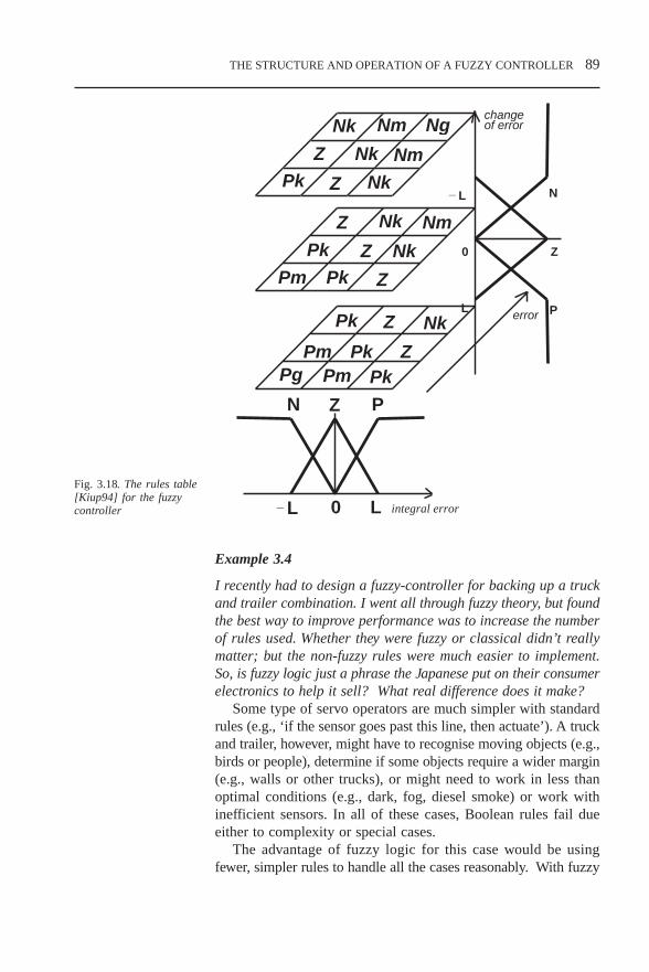
THE STRUCTURE AND OPERATION OF A FUZZY CONTROLLER 89
Nk Nm Ng
Z Nk
Nk
N P
0L L
N
Z
P
0
L
L
Nm
NmNk
Nk
Nk
Z
Z
Z
Z
Z
Z
Pk
Pk
Pk
Pk
Pk
Pk
Pm
PmPmPg
changeof error
integral error
error
_
Z
_
Fig. 3.18. The rules table[Kiup94] for the fuzzycontroller
Example 3.4
I recently had to design a fuzzy-controller for backing up a truckand trailer combination. I went all through fuzzy theory, but foundthe best way to improve performance was to increase the numberof rules used. Whether they were fuzzy or classical didn’t reallymatter; but the non-fuzzy rules were much easier to implement.So, is fuzzy logic just a phrase the Japanese put on their consumerelectronics to help it sell? What real difference does it make?
Some type of servo operators are much simpler with standardrules (e.g., ‘if the sensor goes past this line, then actuate’). A truckand trailer, however, might have to recognise moving objects (e.g.,birds or people), determine if some objects require a wider margin(e.g., walls or other trucks), or might need to work in less thanoptimal conditions (e.g., dark, fog, diesel smoke) or work withinefficient sensors. In all of these cases, Boolean rules fail dueeither to complexity or special cases.
The advantage of fuzzy logic for this case would be usingfewer, simpler rules to handle all the cases reasonably. With fuzzy
CHP3.PM5 6/13/97, 10:23 AM89

90 THE STRUCTURE AND OPERATION OF A FUZZY CONTROLLER
logic you could write three to six rules for size, motion, etc., andsum them. The rules follow more closely what a truck driverstanding behind a truck does: instead of examining every item andplugging in every rule he or she knows about objects and decidesthat something is either ‘a problem’ or ‘can be ignored’ or ‘keepan eye on it’ as the driver is guided backwards. This allows themto ignore cats, birds, open lunch boxes, paper bags, ignorepedestrians who obviously see the truck and are moving at a safedistance from it without having to make a special rule for eachof them. Things like drunks stumbling under the wheels, brokenglass, other trucks or unaware pedestrians receive more attentionbecause they fit into the class of ‘problem items’.
In one sense all measured inputs have some fuzziness even inclassical control. The mechanisms we have available for sensing,feedback and control all have limits to precision. As a result norules will be ‘absolutely accurate’, since the error terms, physicallimitations (e.g., phase-shift and attenuation) and input noise willnormally be a noticeable part of the input. Also filtering inevitablyreduces the legitimate input, attenuating the original signal. Atthat point, fuzzy logic simply recognises what we have been doingall along and ‘hard’ rules are ignored: mapping approximationsonto the response which makes the useful outcome more likely.
3.5.6 Combination of fuzzy and conventional PID controllers
I understand that a fuzzy controller can be particularly good asan operator replacement. In this case can the rules be formulatedby observing an operator’s action?
Yes. We will consider a rules formulation problem in Section4.5 in greater detail.
However, an operator in process control systems usually controlsdifferent technical devices including PID-controllers. Can a fuzzycontroller manage this role?
Sure it can. In this case a fuzzy controller is placed on a higher,more intelligent level. It produces command signals forconventional controllers. Another possible task for a fuzzycontroller in this structure is a future prediction. The famousJapanese subway and helicopter control systems are based onthese principles.
Example 3.5 Hybrid guidance control for a self-piloted aircraft[Bour96]
CHP3.PM5 6/13/97, 10:23 AM90

THE STRUCTURE AND OPERATION OF A FUZZY CONTROLLER 91
A modern aircraft is well equipped with conventional controltechniques and, in particular, various PID controllers whichdemonstrate a good performance and successfully solve differentguidance problems. Guidance control in a modern aircraft isperformed by the PID controllers producing the control signalswhich are applied to ailerons and elevators. The necessaryreference inputs for a PID controller are usually supplied by theaircraft crew based on different data, first of all the currentposition provided through the global positioning system (GPS).
Some piloted aircraft classes are to be replaced withautonomous vehicles which are cheaper in operation and havesome other advantages. The hybrid guidance control system,incorporating conventional PID controllers and a fuzzy controller,is proposed for this aircraft. A fuzzy controller takes the place ofa pilot (an operator) in developing reference signals for a PIDcontroller.
The navigation of the self-piloted vehicle is organised by theonboard GPS receiver tied to a PC-based flight director. Flight-planning software generates a list of consecutive points necessaryto track the mission-determined flight path. Onboard autopilotskeep the aircraft stable, while the flight director (guidance system)interprets the point positions to determine the course, speed, climbrate and turns of the aircraft. The objective of the guidance systemis to bring the aircraft to the next operational point at a specifiedaltitude and to stabilise the vehicle to allow for the operation ofthe onboard photographic and/or measurement equipment. Theaircraft is assumed to be guided to an initial position during thetake-off stage before the guidance system takes over a control.
The designed control structure is shown schematically in Fig.3.19. The altitude of the aircraft is controlled by a low-levelconventional PID feedback controller through aerodynamicailerons and an elevator with mechanical limits of their deflectionangles. A speed of the aircraft is controlled by the throttle setting.The guidance fuzzy controller has to provide reference signals forthe PID controller, which are required roll and pitch angles (φ
ref
and θref
respectively) for a levelled flight, and also to produce thethrottle setting command T
th if a change of altitude is required.
Fig.3.19 Structure of thecombined control system
CHP3.PM5 6/13/97, 10:23 AM91

92 THE STRUCTURE AND OPERATION OF A FUZZY CONTROLLER
An operation of the fuzzy controller developed is illustrated in Fig.3.20. Coordinates of the aircraft current position and of the nextoperational point are used to estimate an offset angle, δ, betweenthe direction to the operational point and the current velocityvector, v, and the rate of change of the offset angle, δ, as well asan altitude difference between the current position of the aircraftand the operational altitude, h, and the rate of change of thealtitude difference h, These estimates become the input signals forthe fuzzy controller and are subject to fuzzification.
The whole control structure consists of three fuzzy controllersoperating independently with each of them having two input andone output signals. This input–output mapping provides a simpletwo-dimensional structure of the linguistic rules sets.
The fuzzy controller output mainly depends on a definitionof the membership functions and the rules. The control variablesδ, δ and h domains are divided into seven linguistic values withthe relative memberships, and the control variable h into five,respectively. The rule definition is subjective and based on theexpert’s knowledge and experience. For a system with twocontrol variables and seven membership functions in each rangeit may lead to a 7 × 7 decision table. The total of three rulessets is used in this fuzzy controller design: for the roll anglecontrol, the pitch angle control and the throttle position control.These rules sets can be viewed as 7 × 7, 7 × 5 and 7 × 5 decisiontables, respectively. As an illustration, the rules set for roll anglecontrol is given in Table 3.7, where equally shaded cells producethe same fuzzy output.
Memberships forinput parameters
Memberships foroutput parameters
δ
δ.
h
h.
Inputparameters
Rule sets
ϕ
θ
Tth
Outputparameters
Set of rulesfor
roll angle
Set of rulesfor
pitch angle
Set of rulesfor
throttle position
Fuzzification Rule evaluation Defuzzification
Fig. 3.20 Operationalblock diagram of thefuzzy control system
·
·
··
·
CHP3.PM5 6/13/97, 10:23 AM92

THE STRUCTURE AND OPERATION OF A FUZZY CONTROLLER 93
Table 3.7
NB NM NS SM PS PM PB
NB LB LB LB LB LB LB LLNM LB LL LL LL LL LL LMNS LL LM LM LM LM LM LLITSM LM LLIT LLIT LLIT LLIT LLIT LMNPS LLIT LMN LMN LMN LMN LMN LLNPM LMN LLN LLN LLN LLN LLN LBNPB LLN LBN LBN LBN LBN LBN LBN
In this table linguistic labels for roll angle are denoted: LB, big;LL, large, LM medium; LLIT, little; the character N denotesnegative.
Simplicity and low hardware implementation cost determine achoice of the membership functions of a singleton type for theoutput parameters (roll angle, pitch angle and throttle position).The linguistic variables of the fuzzy outputs that are evaluated bycycling through the rule sets are projected onto output sets of thememberships.
The defuzzification process takes place after the generation ofthe fuzzy control signals is completed using the inferencemechanism. As more than one fuzzy output variable can beassigned a non zero degree, the contribution of each variable intothe physical output should be taken into account. Thedefuzzification method was based on calculating the centre ofgravity of all fuzzy outputs for each system physical output.
3.6 Stability and performance problems for afuzzy control system
3.6.1 Stability and performance evaluation by observing theresponse
We understand now how a fuzzy controller operates. The nextproblem is how to decide if it functions well?
A control engineer often judges the quality of a control systemby studying the response curve of the system. The curve revealsthe dynamics of the system, responding to changes in its inputs.
So to make a decision, do we need to consider all possible inputs?Of course not. Usually a small set of standard signals are
studied (Fig. 3.21). A unit step input imitating a change of a set-point (Fig. 3.21a), a unit ramp input (Fig. 3.21b) simulatingsmooth change of the operating conditions, and rather seldom, a
δδ·
CHP3.PM5 6/13/97, 10:23 AM93

94 THE STRUCTURE AND OPERATION OF A FUZZY CONTROLLER
parabolic signal (Fig. 3.21c) when one needs to simulate avariable speed of changing.
If a system responds well to these signals, a control practitionerusually judges it as a good system.
What does ‘responds well’ mean?First of all, the system should prove to be stable. Stability is
usually the most important issue to examine in determining thequality of the response (curve) of a system. It is concerned withthe good behaviour of an output of the control system in responseto either external inputs or internal excitations. Stability is a verycomplex theoretical problem, indeed, so complex that there areeven different definitions of stability. Let us take the simplest one.The system is stable if its response for every bounded input isbounded. Practically, it means that for any finite change in itsinput, the system does not produce infinite output change. Orconsidering a unit step input the system response should belimited in magnitude. Figure 3.22a demonstrates some examplesof a unit step response for a stable system, and Fig. 3.22b showsan unstable system.
Fig. 3.21a A unit step input Fig. 3.21b A unit ramp input
0 20 40 60 80 1000
1000
2000
3000
4000
5000
6000
7000
8000
9000
10000
time
0 20 40 60 80 1000
0.2
0.4
0.6
0.8
1
1.2
1.4
1.6
1.8
2
time0 20 40 60 80 100
0
10
20
30
40
50
60
70
80
90
100
time
Fig. 3.21c A parabolic input
CHP3.PM5 6/13/97, 10:23 AM94

THE STRUCTURE AND OPERATION OF A FUZZY CONTROLLER 95
I think it could be unreliable to analyse the system stability justby observing the response curve. Are there some other methods?
Yes, there are. In control theory there are some methods, amongthem:
Nyquist’s stability criteria; Routh’s stability criteria; describing-function approach; phase-plane method.
Unfortunately all of these approaches cannot be used for stabilityanalysis of fuzzy control systems.
Why not?All of them require a special mathematical model of a control
system prior to stability analysis. Nyquist and Routh–Hurwitz’scriteria require a Laplace transform or z transform of amathematical control model. The model is usually required to belinear due to the characteristics of the Laplace transform and ztransform. Furthermore, these two criteria often fail if the controlsystem is time-variant. The describing-function approach fordetermining stability is only approximate. The phase-planemethod usually applies only to first- and second-order systems.
0 20 40 60 80 1001.4
1.6
1.8
2
2.2
2.4
2.6
2.8
3
0 20 40 60 80 1000.2
0.4
0.6
0.8
1
1.2
1.4
1.6
1.8
2
0 20 40 60 80 100-30
-20
-10
0
10
20
30
0 20 40 60 80 1000
5
10
15
20
25
30
35
Fig. 3.22a Examples ofa unit step response for astable system
Fig. 3.22b. Examples ofa unit step response foran unstable system
CHP3.PM5 6/13/97, 10:23 AM95

96 THE STRUCTURE AND OPERATION OF A FUZZY CONTROLLER
Are there any criteria to determine the stability of a fuzzy controlsystem?
Some methods have been proposed based on the Liapunovsecond method. The second method of Liapunov (also referred toas the direct method) is the most general for determining thestability of a nonlinear and/or time-variant system of any order.It is a hot research topic now. But a universal reliable method hasnot yet been put forward. So I would recommend evaluation thestability by observing the system response and its parameters.
3.6.2 Stability and performance indicators
What parameters do you mean?These parameters are marked in Fig. 3.23. Their definitions can
be found in any control textbook. They are overshoot, rise time,settle time. This set of parameters is used to evaluate not just thestability, but the performance of a system as well, and often isgiven in specifications.
So to evaluate the performance, one has to determine the valueof the indicators mentioned above.
Not always. One may apply other indicators. For example,steady state error. Or integral criteria.
Fig. 3.23 Systemperformance parameters
CHP3.PM5 6/13/97, 10:23 AM96

THE STRUCTURE AND OPERATION OF A FUZZY CONTROLLER 97
How should I choose the indicator?Generally speaking, the indicator choice depends on the
problem domain.
Example 3.6 A performance indicator for navigation control.
In Example 3.5, the task was to direct an aircraft to the destinationpoint. The final errors in positioning of the aircraft with respectto the target point and the attitude errors were taken as measuresof performance. The orientation error was defined as the offsetangle between the direction to the arrival point and the directionof the current velocity vector. Figure 3.24 gives an example of thefuzzy control results. In the plot of positioning errors, thedistribution is elliptically spread, indicating a normal distributionof the coordinate errors.
And what about the stability? When is the stability not good?Control systems have a high potential to be unstable if the
following are observed in the response curve of the system:
very fast rise time; high overshoot ratio; very long settle time.
To improve the system stability, one needs to decrease theovershoot ratio and the settle time.
How can I do that?You can adjust either the rules, or the input and output scaling
factors, or some other parameters of a fuzzy controller (SeeChapter 5).
1050
1100
1150
1200
1250
1300
700 800 900 1000 1100 1200 1300 1400
2σ ProbabilityContour
3σ ProbabilityContour Mean=(1081.2,1182.8)
Way point=
, m
, m (1100, 1200)
X
Y
Fig. 3.24 Arrival pointsdistribution for fuzzycontrol
CHP3.PM5 6/13/97, 10:23 AM97

98 THE STRUCTURE AND OPERATION OF A FUZZY CONTROLLER
3.6.3 Stability evaluation by observing the trajectory
There is another method of predicting the stability of the system– observing the order in which the rules are fired. If we drawthis order as a trajectory on the rules table for a good stablesystem, the error and change of error should be graduallydecreased during the rules firing process. It means that we haveto move along this trajectory from the edges of the table to itscentre (Fig. 3.25) decreasing the group number from Group 4towards Group 0.
For an unstable system there is an inverse tendency or at leastthis tendency is not present (Fig. 3.26). Be careful with thesefigures. They must be considered as just examples. And of course,they demonstrate a tendency, not an exact order to follow.
So to make the system stable we need just to provide thecorresponding values for the parameters mentioned above. Howcan I do that?
There can be different ways. The first and most obvious oneis to try to avoid making mistakes in fuzzy controller design. Thewrong choice of the rules and/or membership functions (to a lesserdegree) may make the system unstable. The first thing whichshould be done is check the rules table. The widespread error forthe beginner is the wrong sign for the table output or one of theinputs. It is easy to correct such a mistake. One needs just toreplace NegBig with PosBig, NegSmall with PosSmall, PosBigwith NegBig and so on. Another mistake is the wrong choice ofthe range for possible input or output values.
If one makes no design mistakes, will the system be stable?It is not so simple. Even if one makes no wrong decisions in
the simple structure controller design, the system may still beunstable.
Fig. 3.25 A typicaltrajectory of rules firingfor a stable system
Gr. 0Gr. 1Gr. 2Gr. 3Gr. 4
CHP3.PM5 6/13/97, 10:23 AM98

THE STRUCTURE AND OPERATION OF A FUZZY CONTROLLER 99
3.6.4 Hierarchical fuzzy controllers
What can be done in this case?You may try another structure: try to apply a hierarchical
(multilevel) fuzzy controller or a fuzzy controller with meta rules.In [Wang94] this approach is called a supervisory control. Theidea is pretty simple. The fuzzy controller is designed to satisfythe performance specifications without a serious consideration ofstability problems. As the trade-off between performance andstability is the most common problem in any controller design,this way one is able to simplify the controller design significantlyas well as improve performance.
Hang on! Do we need a good performance when the system isor can become unstable?
No, we do not. This controller has to work and cope withordinary situations. When the situation tends to become dangerousfrom the stability viewpoint another controller has to take control.This second controller is called a supervisory controller.
As the current theoretical methods of proving fuzzy controlsystem stability are limited in their applications, the stable-in-theory top level controller is highly desirable. This demands thecontroller to be constructed as a simple unit with a small numberof inputs and rules. The deviation error can possibly be the singleinput for this controller and it can be implemented with five to
Gr. 0Gr. 1Gr. 2Gr. 3Gr. 4
Fig. 3. 26 A typicaltrajectory of rules firingfor a unstable system
PlantOutputControl
Error
Changeof error
Set-point
Delay ∆t
K
K
++
(Ref.input)
Fuzzycontroller(low level)
Fuzzycontroller(top level)Fuzzy
controller( switch)d
p
_
_
Fig. 3.27 Multilevelstructure of a fuzzycontrol system
CHP3.PM5 6/13/97, 10:23 AM99

100 THE STRUCTURE AND OPERATION OF A FUZZY CONTROLLER
nine rules. This controller should be switched on when thedeviation error is large, and off when it is small. We use roughterms to determine the switching rules as the switcher itself maybe implemented as a fuzzy controller. Undoubtfully this controllershould provide fast convergence of the output(s) to the desiredvalues. The steady-state characteristics of this controller are not veryimportant, because within a short time it will be switched off.
The low level controller(s) can have a complicated structureand achieves the desired steady-state and time responsecharacteristics. In constructing these controllers, all the methodsdeveloped until now can be implemented. The intermediate levelcontroller(s) should provide smooth handing over the controlbetween the levels and eliminate the possibility of oscillationbetween them. The deviation error can be considered as thecontrol input of the switch controller.
Example 3.7 Fuzzy control system for power system stabilisation
One of the main power system stability problems is the low-frequency oscillations of the interconnected electric powersystems. These oscillations may be sustained for minutes andgrow to cause a system separation, if no adequate damping isavailable. The model of one machine infinite-bus power system[Ishig92] is given in Fig. 3.28. Unsurprisingly, the design of astate-of-the-art power system stabiliser (PSS) for improvingstability has received much attention. This stabiliser shoulddemonstrate good performance under small as well as highdisturbances under various operating conditions of the powersystem. The system is equipped with a fast-acting exciter (AVR)and a speed governor (GOV) as controllers. The supplementarystabilising signals U
a and U
g are added to each controller, and
these signals are produced by the fuzzy controller.
Fig. 3.28 The model of apower system stabilisedby a fuzzy controller[Ishig92]
CHP3.PM5 6/13/97, 10:23 AM100

THE STRUCTURE AND OPERATION OF A FUZZY CONTROLLER 101
To solve this problem the structure of the fuzzy control systemwas proposed and tested [Shi95]. The hierarchical fuzzy controlsystem includes a multilayer controller which incorporates twofuzzy controllers on a low level and one on the upper level. Higherlevel supervisory control is used for supervising an operation ofthe direct controllers. Typical tasks of the supervisory controllerare monitoring the power system to determine the operatingmodes, assignment of a direct controller and an adaptationscheme. There are two fuzzy controllers at the lower level: oneis responsible for operation under large perturbation, the otherunder small perturbation.
The supervisory controller monitors a value of the frequencyspeed deviation. When the power system is subject to the largeperturbation, the speed deviation is high and vice versa. The lowerlevel fuzzy controller for the large perturbation has 49 rules tocover the whole operating range, the lower level controller has just24 rules. The dynamic responses of all fuzzy controllers are givenin Fig. 3.29. Comparison analysis has proved that the hierarchicalfuzzy controller provides the same performance as the 24-rulefuzzy controller under the small disturbance condition, however,it provides much better response than the 24-rule controller underthe large disturbance condition.
Will this control system guarantee the stability for any system?That is a good question. It is hard to answer in respect to any
system. [Wang 94] has proved the stability of the hierarchicalsystem satisfying some conditions. Other research has also provedthe stability of a single fuzzy controller under some conditions.
Fig. 3.29 Speeddeviation correspondingto a large disturbance ofa three phase to groundfault
CHP3.PM5 6/13/97, 10:23 AM101

102 THE STRUCTURE AND OPERATION OF A FUZZY CONTROLLER
Fine control
CoarseActuator
Fineactuator
Coarse
control
Exact
position
position
ApproximateFuzzy
controller(top level)
Fuzzycontroller(low level)
Fuzzycontroller( switch)Fig. 3.30 The model of a
compound actuator withthe coarse actuator andthe fine actuatorcontrolled by a fuzzycontroller [Yen92].
∆e
What is the difference? What do we need this multilevel structurefor?
Theoretically these conditions are different. Practically themain advantage is the design simplicity. It is very convenient todesign a fuzzy controller based on just one criterion: eitherstability or performance, not both.
Example 3.8 Servo controller for an optical disk drive [Yen92]
To control a disk drive, the compound actuator is widely used.Data in an optical disk drive is recorded on the disk surface assmall areas of different reflectivity along concentric or spiraltracks. The data tracks are 2 mm apart. With a 5¼-inch disk, theactuator has to move the head across a 5cm stroke and positionit with a 0.1µm error. The compound actuator consists of a fineactuator mounted on the back of a coarse actuator (see Fig. 3.30).The fine actuator has a fast response and a high resolution, whilethe coarse actuator can easily move over large distances.
The fuzzy control system includes two fuzzy controllers. Bothare rather identical in respect to the inputs, output and the rulestable. They use two inputs: the error and the change-of-error. Bothinputs have five classes and the output (control signal) has nineclasses. The following rules table is applied.
Table 3.8
e NB NS Z PS PBNB Z PS PM PL PGNS NS Z PS PM PLZ NM NS Z PS PMPS NL NM NS Z PSPB NG NL NM NS Z
CHP3.PM5 6/13/97, 10:23 AM102

THE STRUCTURE AND OPERATION OF A FUZZY CONTROLLER 103
The difference between fuzzy controllers is in the choice of theinput and output scaling factors. The hierarchical structure is alsoapplied here. To control the compound actuator the following rulesare applied:
if the fine actuator is capable of handling the head movement,it is applied,
if the distance exceeds the fine actuator stroke, then the fineactuator is maintained at the stretched position and the coarseactuator is applied.
The two rules regulate the handover process between the twocontrollers.
CHP3.PM5 6/13/97, 10:23 AM103

104 THE STRUCTURE AND OPERATION OF A FUZZY CONTROLLER
CHP3.PM5 6/13/97, 10:23 AM104

FUZZY CONTROLLER PARAMETER CHOICE 105
HOW TO MAKE IT WORKOR
DESIGN ANDIMPLEMENTATION
OF FUZZY CONTROLLERS
CH4.PM5 6/13/97, 10:26 AM105

106 FUZZY CONTROLLER PARAMETER CHOICE
CH4.PM5 6/13/97, 10:26 AM106

FUZZY CONTROLLER PARAMETER CHOICE 107
4 FUZZY CONTROLLERPARAMETER CHOICE
4.1 Practical examples
4.1.1 Fuzzy autopilot for a small marine vessel
Let us now reconsider our initial design attempt in a moreformalised way. We want to design an autopilot fuzzy controllerto control a movement of a small marine vessel.
Automation of a ship-steering process was initiated during the1920s. Most modern autopilots are based on the PID controllerand have fixed parameters that meet specified conditions[Polk93]. The aim is to keep a vessel moving along thepredetermined trackline with as small a deviation as possible. APID controller works well with a linear plant. In practice,maritime vessels are nonlinear systems. Any changes in thespeed, water depth or mass may cause a change in their dynamiccharacteristics. In addition, the weather conditions will alter theeffects of disturbances caused by winds, waves and currents.
Typical PID autopilots have settings to adjust course andrudder deadbands to compensate for vessel or environmentalchanges. Despite this possibility, the resulting performance isoften far from optimal, causing excessive fuel consumption andrudder wear. These effects are particularly obvious in smallvessels, where the sensitivity to disturbances and controllersettings is far greater than with large ships. Fuzzy controllers arethought to be robust, enabling them to cope with nonlinearchanges arising in ship dynamics and sea conditions.
We will design a fuzzy autopilot for a vessel which proceedsat a forward speed randomly distributed around 3.5 m/s and isto follow straight line tracks with as small a deviation aspossible. A trackline may be up to 10 km in length. Any numberof tracklines may be defined, and they may be parallel ordirected at some arbitrary angle to the previous trackline. Paralleltracklines must be separated by at least 15 m.
The vessel is equipped with a position fixing system which willestablish its position in x and y coordinates with normally
CH4.PM5 6/13/97, 10:26 AM107

108 FUZZY CONTROLLER PARAMETER CHOICE
distributed random errors (standard deviation of 1 m). The headingof the boat is measured with a normally distributed random error(standard deviation of 1 degree).
Table 4.1
Sea state Disturbance
Boat heading Position 3 dB bandwidthw.r.t. current w.r.t. current of disturbance
heading position (Hz)(degrees) (m)
Dead calm 0 0 0.000Slight 5 2 0.200Moderate 10 5 0.125High 20 10 0.100
The guidance requirements are to be accomplished in the presenceof environmental disturbances of wind, waves and varying oceancurrents. For the purpose of this problem, the influence of wind andwaves may be treated as bandlimited random noise affecting thevessel heading and position. Disturbances as high as 10 m and 20degrees may be assumed. The controller should be exercised overa range of environmental disturbances as defined in Table 4.1.
Ocean currents are constant within a given trackline and maybe up to 1.5 m/s and may approach the vessel from any randomlychosen direction.
To give you more information the simulation model of the vesselmovement process in MATRIXx is provided (Fig. 4.1). Because
Fig. 4.1 TheMATRIXxTM simulationmodel for the vesselmovement
CH4.PM5 6/13/97, 10:26 AM108

FUZZY CONTROLLER PARAMETER CHOICE 109
the heading angle and both coordinates can be measured, thismodel has three outputs: the angle (Output 1), and the vesselposition coordinates, x (Output 2) and y (Output 3). This blockhas just one input: the control input, the rudder angle. In thismodel, blocks 4, 6, 16 perform the transformation of the rudderangle into the heading angle. Actually they simulate a ‘pure’(without any disturbance and errors) reaction of the vessel headingon the control signal.
A few blocks simulate disturbance which acts on the heading(block 5) and position (blocks 98, 80, 81, 82). The Disturbance_for_position signal is produced by the block DIST_POS and ispresented by the filtered random signal, the characteristics ofwhich are chosen to satisfy the specifications (see Table 4.1). Thisblock has three outputs to simulate slight, moderate and highdisturbance. To imagine the influence of this disturbance you mayhave a look at Fig. 4.2 which represents one coordinate positiondisturbance only. The structure of the Disturbance_for_headingblock is similar (block DIST_HEAD). This disturbance affectsthe heading angle of the vessel. The current is modelled as havinga constant value, but the angle between the trackline and the oceancurrent direction can be changed. All measured values includemeasurement errors. These errors are modelled as normallydistributed random values and are added to the unmeasured valuesto get real results.
Fig. 4.2 The simulationresult for theDisturbance_for_position
slight disturbance
high disturbance
CH4.PM5 6/13/97, 10:26 AM109
110 FUZZY CONTROLLER PARAMETER CHOICE
All these disturbances are used to simulate a real-life movement.The output of the vessel model (the heading angle) is affected bythe Disturbance_for_heading (block 5) and the measurement error(block 25) to obtain the Heading_angle as the Output_1 for theblock. Also this angle is used to get the movement projections onx and y axes after integration (blocks 87, 7). To simulate themovement, the random signal (normal distribution with the average3.5 m/s and various standard deviations) that is modelling the actualspeed of the boat is used (block 27). To simulate the real lifemovement, the signals modelling the Disturbance_for_position(blocks 98, 80, 81, 82), Ocean_current (blocks 2, 17, 84, 86) andmeasurement errors (blocks 14, 26) are added to get x (Output_2)and y (Output_3) coordinates of the current vessel position.
The values of the Ocean_current magnitude and angle and theDisturbance_for_position angle can be changed while modellingto allow for various cases. The initial conditions in the integratorsmay be changed to model different positions of the object beforethe movement starts. The initial condition in the transfer functionblock allows the model different initial positions of the headingin respect to the trackline direction before the movement starts.This model will be used as a plant model to design a fuzzycontroller.
Do we need a controller? All the disturbances look prettysymmetrical. Will not the influence of any disturbance now becompensated for later on?
Suppose our vessel starts moving along the straight line. In thiscase, we do not need to turn it to keep the trackline. Suppose thatinitially it is directed along the trackline as well. In this case, weare putting our vessel under very favourable conditions. Let ushave a look at Fig. 4.3, which represents the vessel trajectorywithout any controller.
The trajectory is shifted because of the ocean current effect. Weneed just to compensate for this influence.
No. In this figure the movement was simulated in the absenceof any ocean current. If we add the ocean current of 1 m/s, we willhave the trajectory on Fig. 4.4. In this case you see that our vesseldeviates further and further away from the required trajectory. Thesystem is definitely unstable and needs to be controlled.
But without an ocean current, the trajectory is not that bad, is it?No, it is not. Anyway let us see how far we can improve it with
a fuzzy controller, which we are going to design in the nextsections.
CH4.PM5 6/13/97, 10:26 AM110

FUZZY CONTROLLER PARAMETER CHOICE 111
Fig. 4.4 The vesseltrajectory without anycontrol (with the oceancurrent of 1m/s)
Fig. 4.3 The vesseltrajectory without anycontrol (no oceancurrent)
Why are we considering just a simulation? Real life examples aremore interesting.
OK. Before we start improving let me present two realprojects which have been developed and actually implementedby Adaptive Logic, Inc.
CH4.PM5 6/13/97, 10:26 AM111

112 FUZZY CONTROLLER PARAMETER CHOICE
4.1.2 Smart heater control
Example 4.1
The description of this project is given in [Adap96]. Householdappliances that use heaters, such as ovens, rice cookers, andtoasters, should come quickly to the desired temperature andmaintain it regardless of changes in conditions such as load or airflow. Heating elements, because of thermal inertia, require acertain amount of time to change temperature. This latencybetween control and response causes the heater to overshoot andoscillate about the desired temperature. Once the selectedtemperature is achieved, varying environmental conditions oftenthrow the heater back into oscillation. In addition, most heatershave poor temperature control due to the use of crude, on–offswitches. The result is an inefficient and inconsistent operation.
To overcome this drawback, many industrial and consumerproducts as diverse as industrial chambers, ovens, rice cookers,toasters and irons use heating elements that could benefit from theadvantages and feature enhancements of fuzzy logic control. Aheater control has been designed that uses a fuzzy controller tosense the temperature, compare it to the user-selected temperatureand control heater current. The inexpensive, dedicated fuzzy logicdevice is an adaptive controller that prevents thermal instability,providing consistent performance under all conditions.
We will describe both the fuzzy logic rules and design for theheater control. Most appliance heaters are controlled by bimetallicstrips or capillary tubes that expand with heat and switch theheater on or off. These crude mechanical controllers merely reactto temperature fluctuations and cannot anticipate when the heateris approaching the selected temperature. When the element passesthrough the operating point, the switch opens, cutting power tothe heater. But by this time, the heater has enough energy to carrythe system temperature far above the selected range and it takesa while for it to return.
The switch stays open until the heater cools to the correcttemperature. At that point the switch closes, but some time isrequired before the heater can again provide sufficient heat andthe system cools well below the correct temperature. Theovershoot and undershoot process can continue for minutes orhours. A change in the selected temperature or in theenvironment (such as changing air conditions in a heating systemor opening an oven door) may cause the heater to go intooscillation again.
CH4.PM5 6/13/97, 10:26 AM112

FUZZY CONTROLLER PARAMETER CHOICE 113
Heaters have widely varying characteristics. They are specifiedin terms of their form including length, shape, thickness andmaterial composition. Heating elements may add instability to asystem because of their slow response time and thermal inertia.The heater specifications are based on the requirements of the endproduct. The end product also has a range of thermalcharacteristics that influence the behaviour of the heater. Manyvariables of heating systems make the design of a controller fordifferent systems a difficult task. A control system using a fuzzycontroller brings the temperature of the heater to the selectedtemperature quickly and keeps it there regardless of any changesin the load or environment. This results in a more stable andreliable operating temperature.
There are three external inputs monitored by the controller.The first comes from a thermistor to monitor the temperature.The second is the user-selected, desired temperature setting.Input three is, again, the measured thermistor value signal onlydelayed by a small amount of time. This last input enables thecontroller to know the direction and magnitude of thetemperature change in addition to the absolute temperature. Thecontroller samples the input data, processes it and outputs a pulsewidth modulated (PWM) output signal that switches a triaccontrolling the current through the heater.
The fuzzy controller design parameters (inputs, outputs, fuzzyvariables and rules) are given in Fig. 4.5, followed by a briefdescription of the fuzzy controller operation. The main part of anyfuzzy controller is implemented as a set of rules. It performs thecontrol algorithm. By studying the rules, one can see the criteriafor taking actions such as switching the heater on or off. Theserules make decisions based on adjustable membership functiondefinitions. The rules are easily modified to respond to differentcriteria. The following describes the rules’ purposes in relationto the inputs, their associated fuzzy variables, and the action takenwhen a rule is fired.
Timer rules (Rules 1 and 2) are used to generate the timer forpulse switching the triac and to adjust the data processing rate.Rule one increments the ramp output if it is in the countmembership function. When the ramp reaches the reset function,then the reset rule will be fired and return the ramp to zero to beginto increment through the count again. The rate of an increment isset to 12, but could be any non-zero value according to therequirements of the application. The increment and reset actionsimplement a timer that causes the ramp to sweep across an axis.
CH4.PM5 6/13/97, 10:26 AM113

114 FUZZY CONTROLLER PARAMETER CHOICE
The heater output is used to define the centre value ofmembership functions On and Off. On and Off are, in turn, usedby later rules to switch the triac on and off. Rules 3–19 considerboth the current temperature and the previous value of temperaturewhenever the time has reached reset. The winning rule in this groupwill add to or subtract from the value of the heater.
The fuzzy variables classify the temperature as matching theselected value, or being too hot or cold. The membershipfunctions used the user selected temperature (TSET) as a floatingcentre value to compare the selected temperature with the actualtemperature. As the user varies the desired temperature value, themembership function centres move left or right. Other fuzzyvariables use the current temperature value to define their centres.As the temperature varies, the functions shift right or left. Thefuzzy variables compare the current temperature with its time-delayed value. The comparison is a calculation of the derivativevalue and sign of the temperature. By comparing both the currentvalue and derivative of temperature with the desired temperature,one can calculate a temperature correction value based on boththe absolute difference and the rate of change of temperature. Thecalculation allows for precise control and minimises the overshoot.
Rules 3–19 use one fuzzy variable from each set to adjust thevalue of the heater. The actions of the rules are designed to movethe heater towards the desired temperature without causing it toovershoot. Table 4.2 summarises the various conditions andactions of the heater control rules. Note, if all of these rules arenot fired (i.e., the blank boxes scenarios in Table 4.2) then thevalue of the heater is not changed. Some of the rules are describedbelow. Values indicated are added from the heater based upon thewinning condition of TEMP and DELAY. No action is takenwhere there are blanks.
Table 4.2
TEMP TVLOW TMLOW TSLOW TON TSHIGHT MHIGH TVHIGH
DELAY
DLPOS –15
DSPOS –8 –6 –1 –2
DON 25 5 1 0 –1 –5 –25
DSNEG 2 1 6 8
DLNEG 15
CH4.PM5 6/13/97, 10:26 AM114

FUZZY CONTROLLER PARAMETER CHOICE 115
InputsTEMP Measured temperatureTSet Desired temperature settingDelay Delayed measured temperature
OutputsRamp Pulse width rampHeater PWM adjust valueTriac PWM output to triac
Fuzzy variablesHeater Triac ControlRamp is CountRamp is Reset
Timing controlRamp is OnRamp is Off
RulesTiming Ramp Generation1. If Ramp is Count then Ramp + 122. If Ramp is Reset then Ramp = 0
Heater temperature control 3. If TEMP is TON and Delay is DOn and Ramp is Reset then Heater + 0. 4. If TEMP is TVLow and Delay is DOn and Ramp is Reset then Heater + 25. 5. If TEMP is TVHigh and Delay is DOn and Ramp is Reset then Heater –25. 6. If TEMP is TMLow and Delay is DLPos and Ramp is Reset then Heater –15. 7. If TEMP is TMLow and Delay is DSPos and Ramp is Reset then Heater –8. 8. If TEMP is TMHigh and delay is DLNeg and Ramp is Reset then Heater + 15. 9. If TEMP is TMHigh and delay is DSNeg and Ramp is Reset then Heater + 8.10. If TEMP is TMLow and Delay is DOn and Ramp is Reset then Heater + 5.11. If TEMP is TMHigh and Delay is DOn and Ramp is Reset then Heater –5.12. If TEMP is TSLow and Delay is DSNeg and Ramp is Reset then Heater + 2.13. If TEMP is TSLow and Delay is DSPos and Ramp is Reset then Heater –6.14. If TEMP is TSLow and Delay is DOn and Ramp is Reset then Heater + 1.15. If TEMP is TSHigh and delay is DOn and Ramp is Reset then Heater –1.16. If TEMP is TSHigh and Delay is DSNeg and Ramp is Reset then Heater + 6.17. If TEMP is TSHigh and Delay is DSPos and Ramp is Reset then Heater –2.18. If TEMP is TON and Delay is DSNeg and Ramp is Reset then Heater + 1.19. If TEMP is TON and Delay is DSPos and Ramp is Reset then Heater –1.
Over-temperature turn-off20. If TEMP is OverT then Heater –1.
Heater triac control21. If Ramp is Off then Triac = 0.22. If TEMP is OverT then Triac = 0.23. If Ramp is On then Triac = 255.
Fig. 4.5 Fuzzycontroller for a smartheater
Temperature detectionTEMP is TONTEMP is TSHighTEMP is TMHighTEMP is TVHighTEMP is TVLowTEMP is TMLowTEMP is TSLow
Over-temperature detectionTEMP is OverT
Delayed temperature detectionDelay is DLNegDelay is DLPosDelay is DSNegDelay is DSPosDelay is DOn
CH4.PM5 6/13/97, 10:26 AM115

116 FUZZY CONTROLLER PARAMETER CHOICE
Rule 3, for example, is true if the temperature and its previousvalue are in the selected range, and leaves the heater unchanged.Rules 4 and 5 detect the temperature to be far from the selectedvalue and not changing. These rules make large increases ordecreases of the heat. Rules 6 and 7 both consider a medium-lowvalue for the temperature (TMLOW), but they consider differentderivatives and have different action values. Rule 6 considers alarge positive delayed value (DLPOS) while Rule 7 considers asmall one (DSPOS). At first glance, the correction actions for therules may seem to be counterintuitive. In each rule the temperatureis too low, yet the action is to reduce the value of the heater whichdecreases temperature when the heat is stable. The key is that ineach rule the derivative is positive indicating that the temperatureof the heater is increasing. The reduction in the value of heatprevents overshoot while still allowing the temperature to reachthe set point.
The corrective action from Rule 6 is larger than that for Rule7 because in the former rule the derivative value of the airtemperature was larger indicating a faster increase in temperature.The larger previous value subtracts more from the heater (–15)than does the smaller (–8). The same reasoning holds in theremaining rules in the set. As the heater moves closer to thedesired point, other rules will act to gradually hold it there.
Rules 20 and 22 guard against the heating unit from gettingtoo hot. Rule 20 decreases the heater value in small incrementswhen the temperature has gone above the safety level. During thisprocess, at the same time, Rule 22 prevents the PWM control ofthe triac and keeps it off until the temperature decreases to belowthe safety value. Note that Rule 23 (which turns on the pulse) willnever be enacted while the temperature is greater than the safetyvalue. Even if the fuzzy variables Ramp is ON and TEMP isOverT should evaluate to the same value, the precedence goes tothe first rule (Rule 22) for determining the action. If thetemperature is above the safety value, TEMP is OverT willalways be evaluated as a maximum value.
Rules 21–23 control the PWM output, triac, turning it on andoff. The decision is based upon the comparison of the rampfeedback value to the heater value. The heater value serves as acentre for membership functions ON and OFF. As the ramp movesacross count and back to zero, it also moves between the functionsON and OFF. Depending on the value of the heater, the positionof the centre value for the two functions will move to the left orright. That will vary the amount of time during a given sweep that
CH4.PM5 6/13/97, 10:26 AM116

FUZZY CONTROLLER PARAMETER CHOICE 117
the heater is on or off. By moving the heater, one changes the widthof the pulse controlling the triac and the heater temperature.
4.1.3 Active noise control
Another example is provided with the real application results.
Example 4.2Perhaps, there is no more popular problem in telecommunicationengineering than one of noise cancellation. One of the methodsexplored which is called an active noise control (ANC) isproducing an anti-noise signal. Adaptive Logic, Inc. hasdeveloped a solution [Adap96] based on fuzzy controller designand realisation. The solution achieves audio noise reduction ofover –20 dB. By adjusting phase and gain values from themeasured noise level, the controller reduces significantly the
dynamic error measured at the cancellation point. The idea of anANC is to produce an anti-noise signal coinciding with the noisein phase and magnitude to cancel it out. Figure 4.6 shows atypical ANC system that contains a noise source, noise sensor,error sensor and the control or anti-noise source. The system canbe modelled as a closed loop system, where the error is
Fig. 4.6 A typical ANCsystem
Fig. 4.7 Waveformsynthesis for an ANC
CH4.PM5 6/13/97, 10:26 AM117

118 FUZZY CONTROLLER PARAMETER CHOICE
continuously being minimised. Though there are various methodsfor producing the anti-noise, they all rely on the principle that asignal, when added to the inverse of itself, will produce a null.The problem is that in a time variable world, producing the exactinverse signal can be very difficult. Additionally, acousticreflections can add to the original signal producing even morecomplexity in the system. The exact specifications for the anti-noise signal might be known for some very periodic systems. Inthese cases, only the phase and amplitude need to be adjusted. Anexample of such a system might be a large transformer or motor,which being driven at 60 Hz, produces 60 Hz noise andharmonics. For this system, the exact frequency is known so it canbe regenerated, phase shifted and amplitude adjusted to make theanti-noise. Figure 4.7 shows a waveform synthesis system.
For simplicity in this example, the error signal is the RMSvalue of the noise sensor signal. Response time is critical, becauseif set too slow, transients will not be seen, and if too fast, a nullmay never be reached. The controller monitors the error signal,and generates a derivative, so that the direction of the error canbe measured. The derivative is simply produced by copying theerror signal to an output and then on the following cyclecomparing the old stored value at the output (internally fed back)with the new error signal.
By monitoring the error and delayed error, the controller candetermine if the overall error is improving or getting worse.Since this is all the controller knows, it must try parameterchanges to see how they affect the error. In other words, thecontroller does not know if the phase should be increased ordecreased. It only knows that since an error exists, an adjustmentmust be made. If after making an adjustment to the phase oramplitude, the error has improved, then the controller makes thesame adjustment again. When an increase in the error signal ismeasured, the controller ‘takes back’ the last change made,which caused the error to increase. It then begins to adjust theother parameter in the same way before again returning toreadjust the first parameter. It will continually switch back-and-forth between parameter adjustments tuning them for optimalnoise cancellation. By making the adjustment larger when theerror is large, and smaller when the error is small the timeneeded to reach a null can be shortened. Because the dynamicsof this system are slow, audio frequencies, we must be sure thatafter making a change, we wait for the system to respond beforethe change to error is read.
CH4.PM5 6/13/97, 10:26 AM118

FUZZY CONTROLLER PARAMETER CHOICE 119
If the remaining harmonics are high enough to cause concern,they too might need to be cancelled in a similar manner, but witha separate phase and amplitude circuit. For most systems of thistype, only the primary frequency and first harmonic need to becancelled.
The phase accuracy of the anti-noise causes the most changeand therefore error in this type of system. Figure 4.8 illustrates asingle wave being cancelled by its inverse, but with 5 degrees oferror. It can be seen that with only this small degree of error, asignificant signal still remains. This problem is only worsenedwith more complex signals, therefore care must be taken in thephase shifter design. Note that delay in a given system remainsfairly constant over time. This means that the phase shifting circuitneed not vary more than the delay would change over a long term,typically less than 45 degrees. So the resolution of the controllercan be effectively increased by concentrating it to the narrowerregion.
The rule set for this example developed by Adaptive Logic, Inc.is listed in Fig. 4.9. This example uses one analog input, Error,and two analog outputs, Phase and Gain. Two other outputs, Stateand ErrorDly are used for internal variable storage. The Statevariable forms a state machine that controls the flow of thesystem. As discussed earlier, ErrorDly, is used to determine thedirection of Error. In other words it tells the controller if Error isgetting better or worse.
The rules are divided into four sections – one section for eachof the two outputs and two variable registers. For each sampleonly one rule in each section can win. That rule then adjusts theoutput. If no rules are fired, the output does not change.
Fig. 4.8 Error caused bya small phase shift
CH4.PM5 6/13/97, 10:26 AM119

120 FUZZY CONTROLLER PARAMETER CHOICE
The delayed error, ErrorDly, is simply the Error delayed by onesample time. To solve the terms Error is Worse and Error isBetterSame, Error is compared with ErrorDly. If Error is greaterthan ErrorDly, then Error is Worse. Otherwise, it is Better or theSame. There are four Phase and four Gain states. In either case,State 2 increases the parameter, and State 3 decreases it. States 1and 4 are used to provide time for the parameter change to settlebefore checking the response of Error.
To illustrate the efficiency of the fuzzy control methodology,Fig. 4.10 shows the frequency spectrum of a noise source withmany spurious frequencies.
Phase control rules section0. If State is Zero then Phase = 127.1. If State is PHASESTATE2 and Error is High then Phase + 5.2. If State is PHASESTATE3 and Error is High then Phase – 5.3. If State is PHASESTATE2 then Phase + 1.4. If State is PHASESTATE3 then Phase – 1.5. If State is PHASESTATE1 and Error is Worse then Phase – 1.6. If State is PHASESTATE4 and Error is Worse then Phase + 1.
Gain control rules section7. If State is Zero then Gain = 127.8. If State is GainState2 and Error is High then Gain + 5.9. If State is GainState3 and Error is High then Gain – 5.10. If State is GainState2 then Gain + 1.11. If State is GainState3 then Gain – 1.12. If State is GainState1 and Error is Worse then Gain – 1.13. If State is GainState4 and Error is Worse then Gain + 1.
State control rules section14. If State is Zero then State = PHASESTATE1.15. If Error is Zero and State is NotZero then State = PHASESTATE1.16. If State is PHASESTATE1 and Error is BetterSame then State =
PHASESTATE2.17. If State is PHASESTATE2 then State = PHASESTATE1.18. If State is PHASESTATE1 and Error is Worse then State = PHASESTATE3.19. If State is PHASESTATE3 then State = PHASESTATE4.20. If State is PHASESTATE4 and Error is BetterSame then State = PHASESTATE3.21. If State is PHASESTATE4 and Error is Worse then State = GainState1.22. If State is GainState1 and Error is BetterSame then State = GainState2.23. If State is GainState2 then State = GainState1.24. If State is GainState1 and Error is Worse then State = GainState3.25. If State is GainState3 then State = GainState4.26. If State is GainState4 and Error is BetterSame then State = GainState3.27. If State is GainState4 and Error is Worse then State = PHASESTATE1.
Error delayed rules section28. If Anything then ErrorDly = Error.
The frequencies, though centred around 500 Hz, extend down to0 Hz and up to over 6 KHz. The noise level at the peak is about–2 dB. Figure 4.11 shows the cancelled spectrum for this noise
Fig. 4.9 Rule Set
CH4.PM5 6/13/97, 10:27 AM120

FUZZY CONTROLLER PARAMETER CHOICE 121
source. With the active cancellation, the peak noise level is nowat –25 dB and the energy contained in the other frequencies isdramatically reduced. With multinode cancellation otherfrequencies could be further reduced as well.
4.2 Iterative nature of a fuzzy controller designprocessA fuzzy controller design process contains the same steps as anyother design process. One needs initially to choose the structureand parameters of a fuzzy controller, test a model or thecontroller itself and change the structure and/or parameters basedon the test results. You may see that the actual design process
Fig. 4.10 Complex noisesource frequencyspectrum
Fig. 4.11 Cancelledcomplex noise frequencyspectrum
CH4.PM5 6/13/97, 10:27 AM121

122 FUZZY CONTROLLER PARAMETER CHOICE
consists of choosing the controller structure and some parameters(synthesis of the controller) and evaluation of their influence onthe controller stability and performance (analysis of thecontroller). The processes of the analysis and synthesis areinterrelated and interdependable on each other. The process canbe divided roughly into two steps: an initial choice of the structureand parameters, and the subsequent adjustment based on theanalysis. The first step in fuzzy controller design is characterisedby a high degree of subjectivity, and as a result, the second stepmay require a high effort in order to be implemented. This simplealgorithm is presented on Fig. 4.12.
The first step of fuzzy controller design is considered in this chapter,the second step will be presented in Chapter 5. Obviously, the betterthe initial choice, the simpler the second step. One can hope to correctall mistakes later, though, a good start cannot be overrated.
This figure is really pretty simple. However, I have a lot ofquestions. For example, how do I choose parameters? Whichparameters?
Let us consider these problems in greater detail. The classicalfuzzy controller design scheme contains the following steps:
A selection of the input and control variables – a definition ofwhich states of the process shall be observed and which controlactions are to be considered.
A definition of the condition interface – fixing up the way inwhich observations of the process are expressed as fuzzy sets.
A design of the rule base – a determination of which rules areto be applied under which conditions.
A design of the computational unit – supplying algorithms toperform fuzzy computations. Those will generally lead to fuzzyoutputs.
A definition of the rules according to which fuzzy controlstatements can be transformed into crisp control actions.
Structure and parameters initial choice
Testing
No
END
The results are satisfactoryYes
1st step(subjectivity)
Change (tune) parameters2nd step
(high effort)Fig. 4.12 A fuzzycontroller design process
CH4.PM5 6/13/97, 10:27 AM122
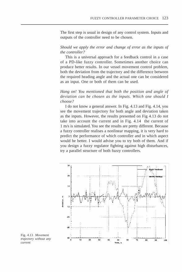
FUZZY CONTROLLER PARAMETER CHOICE 123
The first step is usual in design of any control system. Inputs andoutputs of the controller need to be chosen.
Should we apply the error and change of error as the inputs ofthe controller?
This is a universal approach for a feedback control in a caseof a PD-like fuzzy controller. Sometimes another choice canproduce better results. In our vessel movement control problem,both the deviation from the trajectory and the difference betweenthe required heading angle and the actual one can be consideredas an input. One or both of them can be used.
Hang on! You mentioned that both the position and angle ofdeviation can be chosen as the inputs. Which one should Ichoose?
I do not know a general answer. In Fig. 4.13 and Fig. 4.14, yousee the movement trajectory for both angle and deviation takenas the inputs. However, the results presented on Fig 4.13 do nottake into account the current and in Fig. 4.14 the current of1 m/s is simulated. You see the results are pretty different. Becausea fuzzy controller realises a nonlinear mapping, it is very hard topredict the performance of which controller and in which aspectwould be better. I would advise you to try both of them. And ifyou design a fuzzy regulator fighting against high disturbances,try a parallel structure of both fuzzy controllers.
Fig. 4.13 Movementtrajectory without anycurrent
CH4.PM5 6/13/97, 10:27 AM123

124 FUZZY CONTROLLER PARAMETER CHOICE
4.3 Scaling factor choice
4.3.1 What is a scaling factor?
The first stage of the fuzzy controller operation is fuzzificationand the last one is defuzzification. On both stages, themembership functions which describe different values of thelinguistic variables (or labels) are applied.
What is a scaling factor?To choose membership functions, first of all one needs to
consider the universe of discourse for all the linguistic variables,applied to the rules formulation. To specify the universe ofdiscourse, one must firstly determine the applicable range for acharacteristic variable in the context of the system designed. Therange you select should be carefully considered. For example, ifyou specify a range which is too small, regularly occurring datawill be off the scale (Fig. 4.15b), that may impact on an overallsystem performance. Conversely, if the universe for the input istoo large (Fig. 4.15a), a temptation will often be to have widemembership functions on the right or left to capture the extremeinput values.
For our vessel control system, for the deviation input theuniverse of discourse can be considered as a possible reasonablerange of deviation, for example ± 50 m. If the actual roomtemperature is applied as the input for a control system, then thereasonable range will be between 10°C and 40°C. One needs to
Fig. 4.14 Movementtrajectory with thecurrent of 1 m/s
CH4.PM5 6/13/97, 10:27 AM124

FUZZY CONTROLLER PARAMETER CHOICE 125
-30 -20 -10 0 10 20 300
0.1
0.2
0.3
0.4
0.5
0.6
0.7
0.8
0.9
1NBig NSmall Zero PSmall PBig
Inputs
Wrong choice
Fig. 4.15 Choice of thescaling factors
remember that a reasonable choice in one case can become badin another. It is very hard to give general recommendations.
What can we do in this case?Because of this situation it is usually desirable and often
necessary to scale, or normalise, the universe of discourse of aninput/output variable. Normalisation means applying the standardrange of [–1,+1] for the universe of discourse both for the inputsand the outputs.
Doesn’t it mean that our actual values will be too large or small?It does if we do not modify the structure of the fuzzy
controller. The structure of Fig. 3.10 should be replaced with onegiven in Fig. 4.16.
In the case of the normalised universe, an appropriate choiceof specific operating areas requires scaling factors. An inputscaling factor transforms a crisp input into a normalised input inorder to keep its value within the universe. An output scalingfactor provides a transformation of the defuzzified crisp outputfrom the normalised universe of the controller output into anactual physical output.
What do these scaling factors affect?The role of a right choice of input scaling factors is evidently
shown by the fact that if your choice is bad, the actual operatingarea of the inputs will be transformed into a very narrow subsetof the normalised universe or some values of the inputs will besaturated.
-30 -20 -10 0 10 20 300
0.1
0.2
0.3
0.4
0.5
0.6
0.7
0.8
0.9
1NBig NSmall Zero PSmall PBig
Inputs
Wrong choice
ba
-30 -20 -10 0 10 20 300
0.1
0.2
0.3
0.4
0.5
0.6
0.7
0.8
0.9
1NBig NSmall Zero PSmall PBig
Inputs
Right choice
c
CH4.PM5 6/13/97, 10:27 AM125

126 FUZZY CONTROLLER PARAMETER CHOICE
So the right choice of the input scaling factors is the mostimportant thing.
Wait a minute. Let us consider the role of the output scalingfactor. One can see when the output is scaled, the gain factor ofthe controller is scaled. The choice of the output scaling factoraffects the closed loop gain, which as any control engineer knows,influences the system stability. The behaviour of the systemcontrolled depends on the choice of the normalised transfercharacteristics (control surface) of the controller. In the case of apredefined rules table, the control surface is determined by theshape and location of the input and output membership functions.
4.3.2 Where should the tuning start?
[Palm95] recommends the following priority list:
The output denormalisation factor has the most influence onstability and oscillation tendency. Because of its strong impacton stability, this factor is assigned to the first priority in thedesign process.
Input scaling factors have the most influence on basicsensitivity of the controller with respect to the optimal choiceof the operating areas of the input signals. Therefore, inputscaling factors are assigned the second priority.
The shape and location of input and output membershipfunctions may influence positively or negatively the behaviourof the controlled system in different areas of the state spaceprovided that the operating areas of the signals are optimallychosen. Therefore, this aspect is the third priority.
According to these recommendations, I understand that we haveto choose the output scaling factors and then the input scalingfactors.
It is better to try to make both choices simultaneously. Actuallyall scaling factors influence the performance indicators.
Normalisation
Ref.input
Defuzzification
Process or object under control
fuzzy
output
Controller
membership functionsoutput
Database Rule BaseKnowledge Base
inputcrisp crisp
output
Inference EngineFuzzificationfuzzy
input
inputmembership functions
Rulestable
Denormalization
Fig. 4.16 The structureof a fuzzy controller withthe normalisation anddenormalization blocks
CH4.PM5 6/13/97, 10:27 AM126
FUZZY CONTROLLER PARAMETER CHOICE 127
Yes, like coefficients in PID controllers. Maybe our previousexperience with them can help.
Absolutely! The obvious way is to apply the existingknowledge of classical PID design to a fuzzy controller design.This idea was proposed a rather long time ago [Tang87].
To do it we need to understand the similarity between a fuzzycontroller and a PID controller. We have to analyse therelationship between the scaling factors of a fuzzy controller andthe coefficients of a PID controller.
Exactly! Some research has been conducted in this area. Themost clear recommendations are presented in [Yag94], whichanalysed a fuzzy PI-like controller (Fig. 3.14) in comparison witha classical PI controller. The analysis established the similaritybetween coefficients K
I and K
P of the PI controller and scaling
factors and, proves that a fuzzy controller can be approximatedby a virtual PI controller:
∆u(t) = KI e(t) + K
P ∆e(t)
with parameters:
KI = K
I (K
du K
e) and K
P = K
P (K
du K
d).
From here one can conclude that:
increasing/decreasing the output scaling factor Kdu
causesincreasing/decreasing both coefficients of the corresponding PIcontroller, and therefore, it determines the gain factor of thefuzzy controller;
increasing/decreasing the input scaling factor Ke results in
increasing/decreasing of the parameter KI;
increasing/decreasing the input scaling factor Kde
causesincreasing/decreasing of the parameter K
P.
How can it help in the fuzzy controller parameter choice?If you do not have any experience in a classical PID
controller design, it is no help. However, if one applies theknowledge of PID coefficients’ influence on a controllerperformance, one will be able to use similar rules for tuningscaling factors of a fuzzy controller in the manner identical toa PI controller. The rules derived for tuning a PI-like fuzzycontroller scaling factors are given in Table 4.3. A similarrelationship can be derived for a PD-like and a PID-like fuzzycontroller (see Fig. 4.17).
CH4.PM5 6/13/97, 10:27 AM127

128 FUZZY CONTROLLER PARAMETER CHOICE
Table 4.3 Rules for tuning parameters of a PI-like fuzzy controller [Rez95-2]
Tuning action for
Error attribute Kde Kdu Ke
Steady divergence Decrease Decrease DecreaseOvershoot / oscillation Decrease Decrease DecreaseSpeed of response Increase Increase DecreaseSteady state error Decrease Decr/Inc Increase
As far as I understand these recommendations, they give someadvice of how to tune scaling factors or at least in what directionthey should be shifted. However, they do not explain how tochoose these parameters initially.
I do not agree. The relationship between a fuzzy controllerand a PID controller given in [Yag94] has a global nature. Onecan use them as a basis for other recommendations. For example,one can see that the gain factor of a fuzzy controller could beevaluated approximately as a product of an output and a first inputscaling factor. So initially one can choose the output scaling factorto provide the gain required by the controller specifications. Ofcourse, design is a trial-and-error process. Because oneunderstands how a change of the scaling factors influences theperformance characteristics, one can try different scaling factors,changing their values in a corresponding direction, until thecontroller demonstrates the performance required by thespecifications.
We discussed before that an output scaling factor is determinedby the universe of discourse for the output, similarly for an input.Now you are talking about other reasons.
Sure, if you have a possible output range limited byspecifications, physically or by any other way, you should notcross this boundary. One needs to remember that any controller,including a fuzzy one, produces an output signal, which is appliedto the object under control. This object can impose somelimitations upon the signal. In this case, the output scaling factor
ControlFuzzy
controller
ControlError
Changeof error
Delay
K
K
+
-
∫
K KError
Changeof error
Delay
K
K
+
-
∫
KPID
controllere
d
s
u
e d
p
i
Fig. 4.17 Similaritybetween scaling factorsof a fuzzy controller andcoefficients of a PIDcontroller
CH4.PM5 6/13/97, 10:27 AM128

FUZZY CONTROLLER PARAMETER CHOICE 129
is fixed. Then the input scaling factor should be determined toprovide the required gain for the controller.
Aren’t the same limitations valid for the input?If we use a feedback structure and apply an error signal as one
of the controller inputs, the answer is generally no, becauseusually it is hard to draw up obvious limitations for the errorsignal. However, if we use another specified input, the limitationscan be derived from the controller future behaviour consideration,and these limitations have to be applied to determine the scalingfactors.
Sometimes the right choice of the scaling factor becomes themain problem of a design project. In this case, special attentionis paid to the problem. The scaling factor can be determined, forexample, at early stages of the fuzzy controller design and usedlater.
4.3.3 Application exampleExample 4.3 A camera-tracking fuzzy controller [Lea92]
A control system for managing the traffic around a space stationis under development at the Johnson Space Centre. The firstphase of this development is a camera-tracking system that shouldcontrol the camera gamble drive to keep any object in the fieldof view (FOV) of the camera.
The camera generates measurement results in terms of pixelswhere the field of view is represented with a 512 × 512 pixel map.
A fuzzy controller controls pan and tilt rates based on pixelobject position.
512 pixels
512 pixels
0
Fig. 4.18 Tracking anobject with a camera
CH4.PM5 6/13/97, 10:27 AM129

130 FUZZY CONTROLLER PARAMETER CHOICE
The object tracking means aligning the pointing axis of acamera along the object line of sight (LOS) vector. Themonitoring camera is typically mounted on the pan and tiltgamble drives, which are capable of rotating the pointing axiswithin a certain range. The object LOS vector is estimated fromthe position measurements in terms of pixel (as shown in Fig.4.18) and is an input for a fuzzy controller. The controller outputsthe rotation rate required to align the pointing vector along theLOS vector.
The main problem in the design of this fuzzy controller wasa scaling factor choice. This was because the universe of discourseof the output strongly depended on the position of the object andits velocity in respect to the camera. If the object is very far awayand has a typical approach velocity, its LOS vector is going torotate slowly. If the object is close enough, its approach velocitymay rotate the LOS vector with a high rate. In that case the objectmay go out of the FOV quickly.
To solve this problem, the decision was taken to evaluate thescaling factor depending on the distance. This problem was solvedby the first part of the controller (Fig. 4.19) which outputs a fuzzyestimation of the scaling factor. This estimation is applied to themain part of the fuzzy controller.
One needs to remember that while changing the scaling factors,one actually modifies a linguistic sense of the inputs and outputsof the fuzzy controller. If the only purpose of this change is toimprove a system performance without intending to maintain alinguistic essence of a fuzzy controller, then one may change thescaling factors. However, if the rules base has been formulatedby the expert such an approach cannot be appropriate. Changingthe scaling factors may result in losing the original linguistic senseof a rules base. The experts may not recognise their rules aftertuning the scaling factors and will not be able to formulate newrules.
Fuzzy controller
for gimble ratesTilt rate
Pan ratePixel X position
Pixel Y position
Rules tablefor scaling factor
Distance
Fig. 4.19 The structureof a fuzzy control systemfor a camera tracking
CH4.PM5 6/13/97, 10:27 AM130

FUZZY CONTROLLER PARAMETER CHOICE 131
4.4 Membership function choice
4.4.1 Distributing membership functions on the universe ofdiscourse
We concluded in the previous section that a fuzzy controller wassimilar to a linear PID controller. Is it right?
Yes it is. A fuzzy controller can be approximated as a PID-like controller very roughly. This approximation can be appliedwhen one considers the problem of an initial scaling factorschoice. In a case of a PID controller, a design problem includesa proper choice of the PID-controller coefficients. In a fuzzycontroller design, one needs to choose many more parameters:membership functions, fuzzification and defuzzificationprocedures, etc. These extra parameters make a fuzzy controllermore robust and much more difficult for analysis as well.
In the membership function choice, one has to solve a fewproblems: how to choose general parameters, such as the numberof classes (membership functions) to describe all the values of thelinguistic variable on the universe, the position of differentmembership functions on the universe of discourse, the width ofthe membership functions, and concrete parameters, such as theshape of a particular membership function.
We will try to provide general recommendations first of all.Let us start with the position of the classes on the universe.Suppose we have three classes: high, medium and low with themembership functions given in Fig. 4.20. What do you suggesthere?
0 5 10 15 20 25 300
0.1
0.2
0.3
0.4
0.5
0.6
0.7
0.8
0.9
1Low Medium High
Fig. 4.20 Membershipfunctions (classes)distribution
CH4.PM5 6/13/97, 10:27 AM131

132 FUZZY CONTROLLER PARAMETER CHOICE
I guess it is not very good. If we take, for example, a real inputsignal of 16, it does not correspond to any class (the degree ofmatching any class is 0). It means that this real input does notfire any rule so the controller does not react on this input. If themembership functions distribution is supposed to describe outputclasses in some defuzzification methods, the area on whichintegration is performed will be discontinued.
I agree that the membership functions describing differentclasses should overlap. But how much? Which overlap is better,Fig. 4.21a or b? The choice of membership functions remains asthe most undeveloped problem in fuzzy controller design.
Software design packages propose different ways to definemembership functions but give no, or in the best case verygeneral, recommendations on how to select the membershipfunction shape and width. Although some theoretical [Kre92] andpractical [Fuz92] suggestions have been already made, this choiceis based mainly on professional experience and common sense.
4.4.2 An evaluation of the membership function width
The first step in a width selection should be the choice of aparameter to evaluate it. The absolute value of the width is notappropriate as it does not compare the width of the separatemembership function with the number of classes and the universeof discourse. [Mar92] has proposed two indices which meet thisdemand: the overlap ratio and the overlap robustness. Theseindices evaluate a width of membership functions through theoverlap of two adjacent functions. The idea is very fruitful,because it allows us to compare the scope of the separatemembership function with the universe and the number of classes.
[Mar92] considered just linear membership functions, and these
0 5 10 15 200
0.1
0.2
0.3
0.4
0.5
0.6
0.7
0.8
0.9
1
0 5 10 15 200
0.1
0.2
0.3
0.4
0.5
0.6
0.7
0.8
0.9
1
Fig. 4.21 Membershipfunctions distributionwith different overlaps
a) b)
CH4.PM5 6/13/97, 10:27 AM132

FUZZY CONTROLLER PARAMETER CHOICE 133
indices worked very well. They can easily be calculated for allmembership functions with a limited discourse area, however, thisis not the case for functions with an infinite discourse area, forexample, an exponential (Gaussian) membership function.Moreover, the first index does not depend on the membershipfunction shape at all and the second one depends on the shapewithin the overlap area only.
For these reasons we would like to propose the index of thewhole overlap:
∫ x min (µ
1 (x), µ
2 (x))
WO =∫
x max (µ
1 (x), µ
2 (x))
where µA(x) and µ
B(x) are two adjacent membership functions.
The evaluation formulas for this index and some usualmembership functions are given in Table 4.4.
Fine. But what do we need this parameter for?We can see that the index of the whole overlap (WO) can easily
be calculated in the cases of membership functions with theunlimited discourse area as well as in the cases of simple functionswith a limited area. Also it gives us complete information aboutthe width of a membership function, comparing it with a numberof classes and an area of discourse. Judging all of these reasons,we can choose this parameter as a base to evaluate its influenceand the influence of the membership functions position on thedifferent performance indicators of a fuzzy controller.
Fig. 4.22 A wholeoverlap parameterevaluation
CH4.PM5 6/13/97, 10:27 AM133

134 FUZZY CONTROLLER PARAMETER CHOICE
Table 4.4 Whole overlap parameter for some membership functions
Membership function Formula WO ratio
Linear µ(x) = 1 – abs((x – m)/σ)(triangular)
Exponential (Gaussian) µ(x) = exp[–((x – m)/σ)2]
Quadratic µ(x) = max (0, 1 – ((x –m)/σ)2)
The research results [Rez93] let us make the following assertions:
The parameter of the whole overlap is appropriate for anevaluation of a membership function width as it compares thewidth of a separate membership function with the area ofdiscourse and the number of classes.
Use of narrower membership functions results in a fasterresponse (smaller response time).
Larger oscillation, overshoot and settling time appear whennarrower membership functions are used.
Use of narrower membership functions produces the systemwith lower steady-state error. But with a very narrow function,the steady state may possibly not be reached at all.
The choice of the defuzzification method does not significantlyinfluence the system performance characteristics.
The presence of small noise and disturbances generally keepsthe statements made above valid.
If we compare an action of a fuzzy controller with the action ofa conventional PID controller, we can state that when we decreasea membership function width (decrease the WO ratio), we increasethe differential part, and in the opposite case we emphasise anintegration performance of the controller. So we can see someanalogy between a membership functions choice and a PIDcontroller coefficients choice similar to that we established for ascaling factor choice.
Has large noise presence been considered in this research?Yes, it has. Generally speaking in the presence of large
2
3 2
1
3 22
3 2
1
3 2
2 1 2 1 3
2 1 2 1 3
−−
+−
+−
−−
m m m m
m m m mσ σ
σ σ
( )
( )
1
22
12 1F
m m( )
− −
σ
12
12
12 1 2( )−
− −m m
σ
CH4.PM5 6/13/97, 10:27 AM134

FUZZY CONTROLLER PARAMETER CHOICE 135
disturbances it would be better to apply a fuzzy controller with ahigher overlap.
4.4.3 Application exampleExample 4.4 A temperature control servo system
A control servo system keeps a constant temperature for aconventional water heater tank. The water heater basically hasfive outputs: the temperature error (the difference between thedesired temperature and the real one) and four other states relatedto the water level of the tank itself. Initially only the temperaturewas examined. If the temperature is too high, then the amount ofnecessary heat is less than the current amount. If it is too low, thenmore heat is necessary. The fuzzy controller with differentmembership functions has been used to control this plant. In Fig.4.23 step responses of this control system with different overlapsare given. The Gaussian membership functions and means ofmaximum defuzzification methods were applied.
This was a simple example and even here one can see that suchresponse parameters as the steady-state error, overshoot, settlingtime do depend on the overlap and consequently on themembership function choice. A more complicated one is ourvessel control.
Example 4.5 A vessel movement control system
Figure 4.24 presents two different trajectories realised by similarfuzzy controllers. The only difference was in the overlap of thecontroller input and output membership functions. You see that theresults obtained are quite different.
Fig. 4.23 The stepresponse for the tanktemperature controlsystem with variousoverlaps
CH4.PM5 6/13/97, 10:27 AM135
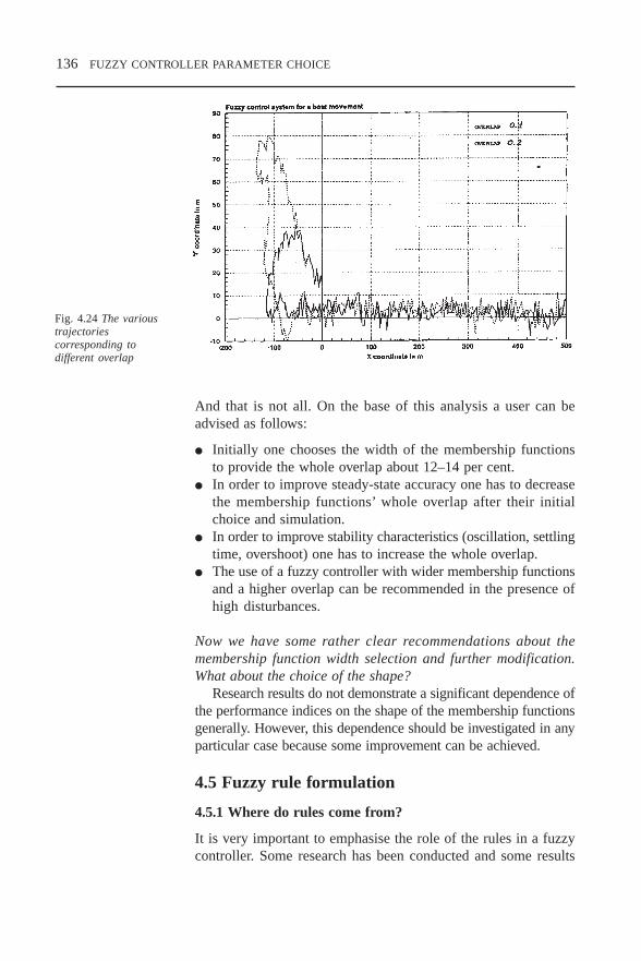
136 FUZZY CONTROLLER PARAMETER CHOICE
And that is not all. On the base of this analysis a user can beadvised as follows:
Initially one chooses the width of the membership functionsto provide the whole overlap about 12–14 per cent.
In order to improve steady-state accuracy one has to decreasethe membership functions’ whole overlap after their initialchoice and simulation.
In order to improve stability characteristics (oscillation, settlingtime, overshoot) one has to increase the whole overlap.
The use of a fuzzy controller with wider membership functionsand a higher overlap can be recommended in the presence ofhigh disturbances.
Now we have some rather clear recommendations about themembership function width selection and further modification.What about the choice of the shape?
Research results do not demonstrate a significant dependence ofthe performance indices on the shape of the membership functionsgenerally. However, this dependence should be investigated in anyparticular case because some improvement can be achieved.
4.5 Fuzzy rule formulation
4.5.1 Where do rules come from?
It is very important to emphasise the role of the rules in a fuzzycontroller. Some research has been conducted and some results
Fig. 4.24 The varioustrajectoriescorresponding todifferent overlap
CH4.PM5 6/13/97, 10:27 AM136

FUZZY CONTROLLER PARAMETER CHOICE 137
have been achieved. If one tries to classify the approaches appliedto the rules derivation [Lee90], the results are as Table 4.5 andSection 8.7.
Table 4.5 Main approaches and sources of fuzzy controller rules
Expert experience and knowledge.Operator’s control actions learning.Fuzzy model of the process or object under control usage.Learning technique application.
The first approach comes from an expert systems domain. Thereason for that is pretty obvious: any fuzzy controller is actuallyan expert system applied to control problems. All theoretical andpractical methods of knowledge acquisition developed in artificialintelligence and other sciences are to be applied here. It should benoted that by using linguistic variables, fuzzy rules provide a naturalframework for human thinking and knowledge formulation. Manyexperts find that fuzzy control rules provide a convenient way toexpress their domain knowledge. So cooperation with the expertswill be easier for a knowledge engineer.
How do we find the rules practically? I mean how should thisprocess be organised?
Two methods can be proposed based on work with thedocumentation or the experts themselves. The first one is based onredeveloping manuals, operation instructions and any otherdocuments available into the set of the rules. Another way includesan interrogation of experienced experts or operators using a carefullyorganised questionnaire. Of course, a good knowledge engineeralways tries to apply the combination of these two approaches.
Another method is pretty similar to the first one. Here the rulesare formulated by observing how a skilled operator controls theobject or the process. In this case the operator should be an expert.As was pointed by Sugeno, in order to automate a control process,one can express the operator’s control rules as fuzzy if–then rulesemploying linguistic variables. In practice, such rules can bededuced from observation of the human controller’s actions.
Both of the approaches proposed seem rather subjective,depending on an expert opinion. Is there another method basedon for example, some measured data?
Yes, there are two other methods. The first one is thegeneration of a set of fuzzy control rules based on the fuzzy model
CH4.PM5 6/13/97, 10:27 AM137

138 FUZZY CONTROLLER PARAMETER CHOICE
of the process or object under control. This approach isideologically similar to a classical controller design technique inwhich we derive a mathematical model of the controller from themathematical model of the plant. Here the mathematical plantmodel is fuzzy.
Another method is based on learning and experience gained.This method supposes employing adaptive and/or self-organisingfuzzy controllers and is to be considered in Section 5 in greaterdetail.
All of these methods suppose a heuristic (at least initially)derivation of the fuzzy control rules. Obviously, there is a needin the following analysis and justification of the rules.
I understand that the rules are formulated on the base of someknowledge about the process, object or some data available. Whatcan we do if almost nothing is available?
Although any special knowledge is very valuable in rulesformulation, do not underestimate the ‘classical’ examples of thePID-like fuzzy controllers’ rules. This can be a good starting pointfor many cases, especially with the analysis and adjustment tofollow.
4.5.2 How do we get rules?Example 4.6 Fuzzy controller for automated delivery of musclerelaxants [Mas94]
Anaesthetists are familiar with administering bolus injections ofnondepolarising muscle relaxants at more or less regular intervalswith minimal feedback as to the level of muscle relaxation.Computer controllers are needed nowadays to regulate thecontinuous infusion of muscle relaxant to match each individualpatient’s needs, avoiding overdose and maintaining stablerelaxation. A fuzzy self-organising controller was proposed in[Mas94] for this problem. As there was no expertise availableto build the rule base, because anaesthetists are not generallyaccustomed to controlling muscle relaxation by a continuousinfusion, a general technique was applied. A PD-like fuzzycontroller with two inputs was proposed: inputs were error andchange of error, with the error being the deviation from the desiredlevel of muscle relaxation. The output of the controller was theinfusion rate. This controller has the following rule base (Table4.6). One can see that a standard PD-like fuzzy controller wasapplied here because of the absence of special knowledge.
CH4.PM5 6/13/97, 10:27 AM138

FUZZY CONTROLLER PARAMETER CHOICE 139
Table 4.6 Rule base for a fuzzy controller for automated delivery ofmuscle relaxants
NB NM NS Z PS PM PB
NB NB NB NB NM NM NS Z
NM NB NB NM NM NS Z PS
NS NB NB NS NS Z PS PM
NO NB NM NS Z Z PM PB
PO NB NM Z Z PS PM PB
PS NM NS Z PS PS PB PB
PM NS Z PS PM PM PB PB
PB Z PS PM PM PB PB PB
4.5.3 How do we check if the rules are OK?
Usually the rules are formulated one by one. After this, one hasto analyse the whole set of the rules. In this analysis, one needsto determine if the set of the rules is:
complete; consistent; continuous.
How do we do that?Let me start with the definitions. The rules set is complete if
any combination of input values results in an appropriate outputvalue. Any combination of inputs should fire at least one rule.
Example 4.7 The fuzzy controller has the following rules set(Table 4.7).
Table 4.7
NB NS Z PS PB
NB 11 12 PB13 PS14 Z15
NS 21 PB22 PS23 PS24 Z25
Z PS31 PS32 Z33 Z34 NS35
PS Z41 Z42 NS43 NS44 NB45
PB NS51 NS52 NB53 NB54 NB55
Is this rules set complete?
I do not think it is, as there are some empty cells in the table. Itmeans that some combinations of the inputs: (NB,NB), (NS,NB)
e∆∆∆∆∆e
e∆∆∆∆∆e
CH4.PM5 6/13/97, 10:27 AM139
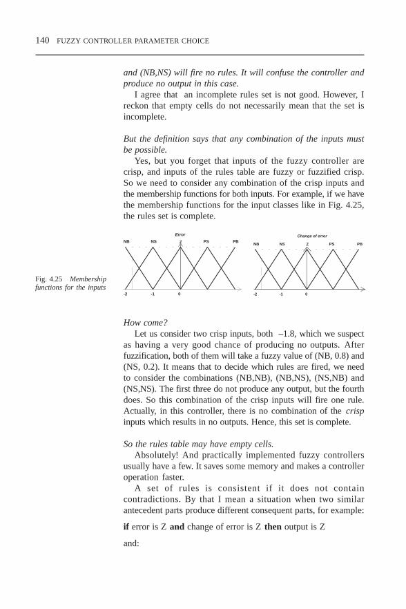
140 FUZZY CONTROLLER PARAMETER CHOICE
and (NB,NS) will fire no rules. It will confuse the controller andproduce no output in this case.
I agree that an incomplete rules set is not good. However, Ireckon that empty cells do not necessarily mean that the set isincomplete.
But the definition says that any combination of the inputs mustbe possible.
Yes, but you forget that inputs of the fuzzy controller arecrisp, and inputs of the rules table are fuzzy or fuzzified crisp.So we need to consider any combination of the crisp inputs andthe membership functions for both inputs. For example, if we havethe membership functions for the input classes like in Fig. 4.25,the rules set is complete.
How come?Let us consider two crisp inputs, both –1.8, which we suspect
as having a very good chance of producing no outputs. Afterfuzzification, both of them will take a fuzzy value of (NB, 0.8) and(NS, 0.2). It means that to decide which rules are fired, we needto consider the combinations (NB,NB), (NB,NS), (NS,NB) and(NS,NS). The first three do not produce any output, but the fourthdoes. So this combination of the crisp inputs will fire one rule.Actually, in this controller, there is no combination of the crispinputs which results in no outputs. Hence, this set is complete.
So the rules table may have empty cells.Absolutely! And practically implemented fuzzy controllers
usually have a few. It saves some memory and makes a controlleroperation faster.
A set of rules is consistent if it does not containcontradictions. By that I mean a situation when two similarantecedent parts produce different consequent parts, for example:
if error is Z and change of error is Z then output is Z
and:
0-1-2
NB NS Z PS PB
Change of errorNB NS Z PS PB
0-1-2
Error
Fig. 4.25 Membershipfunctions for the inputs
CH4.PM5 6/13/97, 10:27 AM140

FUZZY CONTROLLER PARAMETER CHOICE 141
if error is Z and change of error is Z then output is NB.
This is an obvious mistake and one of the rules must be excluded.A set of rules is continuous if it does not have neighbouring
rules with output fuzzy sets that have an empty intersection.
Hang on. Which rules are neighbouring? And what is thisintersection?
We can define ‘neighbouring rules’ as follows: two rules areneighbours if their cells are neighbours. In the previous rules table,Rule 33 has neighbouring Rules 23, 32, 34, and 43. An intersectionmeans that the rules do not allow a jump in output value for a smallchange in an input value. We have decided that a crossing pointbetween two adjacent membership functions should not be zero. Itmeans that this property requires a change to the adjacent class inany input to result in a change to an adjacent class in the output.If this small change in an input results in jump over a neighbouringclass, the rules set is discontinuous.
What is wrong with this set?In some situations, it could not provide smooth control.
Sometimes it may significantly decrease the controller performance.Rules can be formulated on a base of not just professional
experience but a common knowledge and even common sense.An antecedent part of any rule may contain non-measured inputswhich can be determined as fuzzy inputs initially, although thisis not widespread in control applications. For example, in theproblem of colouring a map [Ter94] the following rules are given:
if season is spring then colour is rather light greenif season is winter then colour is slightly grey brown.
4.5.4 Application examplesExample 4.8Let us come back to our vessel control again and consider therules sets in Tables 4.8 and 4.9.
Table 4.8
NB NS Z PS PBNB PB PB PB PS ZNS PB PB PS Z NSZ PB PS Z NS NBPS PS Z NS NB NBPB Z NS NB NB NB
∆∆∆∆∆ee
CH4.PM5 6/13/97, 10:27 AM141

142 FUZZY CONTROLLER PARAMETER CHOICE
Table 4.9
NB NS Z PS PBNB PB PB PB PB ZNS PB PB Z Z NBZ PB PB Z Z NBPS PB Z NB NB NBPB Z NB NB NB NB
Now try to compare these tables.
I see that the second table represents the discontinuous set of therules.
And a result of this you may see in Fig. 4.26. The trajectoryis quiet different from the previous one.
Example 4.9 AC induction motor fuzzy controller [Clel92]
The most important challenge to reducing motor powerconsumption is to vary properly the shaft speed of motors whichare designed as constant-speed machines. Electric motors useover 60 per cent of the electrical power generated in the UnitedStates[Bald87]. The efficiency of a constant-speed induction motorcan drop drastically under reduced loads. To minimise powerlosses, it is necessary to control a motor speed and thereby adjustthe motor speed to the load requirements. The most recent andsuccessful approach is an adjustable speed drive (ASD). Anembedded fuzzy controller can be added to conventional ASDs.
Fig. 4.26 Continuous anddiscontinuous rules setapplications
∆∆∆∆∆ee
continuous control
discontinuouscontrol
CH4.PM5 6/13/97, 10:27 AM142
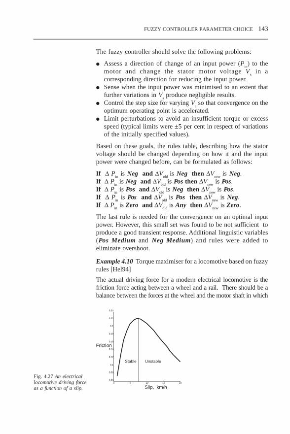
FUZZY CONTROLLER PARAMETER CHOICE 143
The fuzzy controller should solve the following problems:
Assess a direction of change of an input power (Pin) to the
motor and change the stator motor voltage Vs in a
corresponding direction for reducing the input power. Sense when the input power was minimised to an extent that
further variations in Vs produce negligible results.
Control the step size for varying Vs so that convergence on the
optimum operating point is accelerated. Limit perturbations to avoid an insufficient torque or excess
speed (typical limits were ±5 per cent in respect of variationsof the initially specified values).
Based on these goals, the rules table, describing how the statorvoltage should be changed depending on how it and the inputpower were changed before, can be formulated as follows:
If ∆ Pin
is Neg and ∆Vold
is Neg then ∆Vnew
is Neg.If ∆ P
in is Neg and ∆V
old is Pos then ∆V
new is Pos.
If ∆ Pin
is Pos and ∆Vold
is Neg then ∆Vnew
is Pos.If ∆ P
in is Pos and ∆V
old is Pos then ∆V
new is Neg.
If ∆ Pin
is Zero and ∆Vold
is Any then ∆Vnew
is Zero.
The last rule is needed for the convergence on an optimal inputpower. However, this small set was found to be not sufficient toproduce a good transient response. Additional linguistic variables(Pos Medium and Neg Medium) and rules were added toeliminate overshoot.
Example 4.10 Torque maximiser for a locomotive based on fuzzyrules [Hel94]
The actual driving force for a modern electrical locomotive is thefriction force acting between a wheel and a rail. There should be abalance between the forces at the wheel and the motor shaft in which
Fig. 4.27 An electricallocomotive driving forceas a function of a slip.
0 5 10 15 200.06
0.08
0.1
0.12
0.14
0.16
0.18
0.2
0.22
0.24
Slip, km/h
Friction
Stable Unstable
CH4.PM5 6/13/97, 10:27 AM143

144 FUZZY CONTROLLER PARAMETER CHOICE
a drive introduces a motor torque. The friction force depends on theslip and generally is a nonlinear function with parameters determinedby the velocity of the locomotive and the quality of the wheel-railconditions. Ideally the slip-friction curve should have a maximum ora plateau and can be divided into two regions: stable and unstable.
For the stable region (the rising branch of the curve) a non-controlled dynamic system vehicle-rail is always stable if therequired motor torque in addition to the forces of inertia, dampingforces and spring forces does not exceed the maximum of thefriction force. However, if an increase of the motor torque disturbsthe force balance, the system can be stabilised again. The aim ofthe torque maximiser is to keep the system characteristics closeto the optimum point where the friction reaches the maximum.It is done by calculating the value of the slip correction (corr),which depends on the part of the curve the system is working atthe moment. If the system reacts with a positive (or negative)change of the friction force Df, when a positive (or negative) slipcorrection is introduced, it means that the system is working onthe stable branch of the curve. Otherwise, the system is in theunstable region. Because the closer the system is to the optimalpoint, the smoother the curve, a rough value for the correction canbe determined on the base of the absolute values of the previousslip correction and force reaction. This description allows toformulate 25 rules in the table.
Table 4.10
NB NS Z PS PB
NB PB PS Z NS NB
NS PS PS Z NS NS
Z Z Z Z Z Z
PS NS NS Z PS PS
PB NB NS Z PS PB
To examine this controller, several tests have been performed[Hel94] simulating different operating conditions. Theperformance of the fuzzy controller has been evaluated againstdifferent criteria. This controller has demonstrated betterperformance than the conventional PI controller.
In the rules design, sometimes it is useful to subdivide a wholefuzzy controller into two parts. The second part can be consideredas a main controller, while the first one is a preparation part. Thegoal of the first part is to produce fuzzy signals which are used
∆s∆f
CH4.PM5 6/13/97, 10:27 AM144

FUZZY CONTROLLER PARAMETER CHOICE 145
in the rules table of the second part. In this way, the preparationpart can be applied to solve classification problems.
Example 4.11 Automotive automatic transmission fuzzy control-ler [Hir93]
This fuzzy controller is used for a shift scheduling of automatictransmission vehicles. Usually the vehicle velocity and the throttleangle are the only two factors that are applied for determinationof the shift scheduling in an automatic transmission. The influenceof these factors can be expressed with the following rules:
If speed is low and throttle is low then shift +1.If speed is low and throttle is high then shift –3.If speed is high and throttle is low then shift +3.If speed is high and throttle is high then shift –1.
By contrast, a driver using a manual transmission makes the gearshift decision based on a consideration of some extra factors, suchas the road resistance, the current shift, the brake time, the vehicleacceleration. To improve a shift scheduling, one can introducesome extra rules describing the influence of these extra factors:
If resistance is NegBig and throttle is Close and shift isNotLow then shift –2.If speed is Low and shift is High then shift is –3.If brake time is Long and shift is NotLow then shift is –2.
An introduction of the extra rules makes the controller operationsimilar to a human driver. Considering these rules in combinationwith the previous set, one can significantly improve a performanceof the controller, especially in uphill driving.
Example 4.12 Siemens automatic transmission control [Hel94]
Let us consider how this rules table can be generated in greaterdetail. Taking into account inputs from the accelerator and brakepedals, gearbox and other areas, and processing them with thehelp of two dozen rules, a fuzzy controller can deduce whethera vehicle is climbing or descending, and thus optimise vitalmotor functions to meet not only the driver’s habits and style, butto enhance safety and reduce fuel consumption. The fuzzy controlsystem can consist of two parts: the preparation part and thecontrol. The first part receives seven input signals (e.g. throttleopening, dki, change in dki, etc.) and produces three output signals(Fig. 4.28): one is used for the load detection, one for the driver
CH4.PM5 6/13/97, 10:27 AM145

146 FUZZY CONTROLLER PARAMETER CHOICE
classification and one is a shift signal indicating whether this shiftis allowed or not. Both the load and driver signals are used tochoose a shift pattern.
The importance of a shift pattern adaptation to the driver and loadcould be illustrated with the following example. In the case of anincreasing load or a sporty driver, shift patterns with flat curvecharacteristics are selected. This leads to a delay in shifting upor even to shifting down. Therefore, the engine will run at a higherspeed. The third signal (indicating which shift is allowed) limitspossibilities, depending on the engine construction. For example,if there are four gear positions available, it is not possible to shiftup when driving in the fourth gear. Shifting down must beforbidden when driving too fast for a lower gear position.
This part allows us to prepare conditions for a proper gearchoice. The system includes some rules describing the behaviourof a normal driver, for example:
If dki is Very Big and nab
is Not Very Big and Dnab
is Not Positivethen load is Mountain.
Another set of rules allows us to take into account the typicalbehaviour of a driver. The driver classification depends on thechange of throttle opening and the changes of it, for example:
If ∆dki is High and ∆nab
is High then the driver is sporty.
The shift signal has four discrete states: Shift Forbidden, ShiftAllowed, Shift Down Forbidden, Shift Up Forbidden. The rulesincluding this input in their antecedent parts provide a proper tech-nological system behaviour and a system security.
Fig. 4.28 Thepreparation part of thefuzzy controller
CH4.PM5 6/13/97, 10:28 AM146

FUZZY CONTROLLER PARAMETER CHOICE 147
4.6 Choice of the defuzzification procedureHere we give a very brief description of the most widely useddefuzzification procedures and compare them. Let me remind youthat the defuzzification goal in Mamdani-type fuzzy controllersis to produce a crisp output taking the fuzzy output obtained afterrules processing, clipping or scaling (see Fig. 3.7). Nodefuzzification is necessary in a Sugeno-type fuzzy controller.Because the input for the defuzzification procedure is the clipped(or scaled) membership function, most of the methods propose theprocedure of calculating the integrated evaluation of this input.
We will consider the following methods:
Centre-of-area/gravity defuzzification. Centre-of-largest-area defuzzification. Mean of maxima. First-of-maxima defuzzification. Middle-of-maxima defuzzification. Height defuzzification.
Why are there so many methods?I suppose the main reason is that none of them has proved
its advantage over others. Nowadays the choice of thedefuzzification procedure is based mainly on personal preference.It is even hard to introduce these methods, as different authorssometimes name the same procedure differently.
The first two methods tend to produce an integral outputconsidering all the elements of the resulting fuzzy set with thecorresponding weights. Other methods take into account just theelements corresponding to the maximum points of the resultingmembership functions.
4.6.1 Centre-of-area/gravity
The centre-of-area method (in the literature also referred to as thecentre-of-gravity method) is the most well-known defuzzificationmethod. In the discrete case (when we have some values of theoutput signal with the corresponding membership degrees u
1/µ
(u1), ..., u
k/µ (u
k) ) this results in
kΣ u
i * µ(u
i)
i = 1u* =
kΣ µ(u
i)
i = 1
CH4.PM5 6/13/97, 10:28 AM147

148 FUZZY CONTROLLER PARAMETER CHOICE
In the continuous case we obtain
∫ U
u * µ(u) du u* =
∫ U
µ(u) du
where ∫ is the classical integral and µ (u) is a combined member-ship function.
This method determines the centre of the area below the combinedmembership function (Fig. 4.29).
This method sometimes includes a threshold or an indexelement T. Its application eliminates in the evaluation of u* thoseelements u
i where the membership degree is less than T. This
threshold is selected at a value that reflects disturbances in bothinput data and properties of the object under control. In this case,the result is the centre of the area between the threshold and thecombined membership function.
It can be seen that this defuzzification method takes into accountthe area of U as a whole. Thus, if the areas of two clipped fuzzysets are overlapped, then the overlapping area is not paid anyparticular attention. Because of integration, this operation iscomputationally rather complex and therefore results in quite slowinference cycles.
4.6.2 Centre-of-largest-area
The centre-of-largest-area is used in the case when U is non-convex, i.e. it consists of at least two convex fuzzy subsets whichare not overlapped. Then the method determines the convex fuzzysubset with the largest area and defines the crisp output value u*to be the centre-of-area of this particular fuzzy subset (Fig. 4.30).It is difficult to represent this defuzzification method formally,because it involves first finding the convex fuzzy subsets, then
Fig. 4.29 Centre-of-areadefuzzification method
CH4.PM5 6/13/97, 10:28 AM148

FUZZY CONTROLLER PARAMETER CHOICE 149
1
0u
U
computing their areas, etc.In this method the defuzzification result is biased towards a sideof one membership function. It does not take into account otherparts of the clipped (scaled) membership function. Why not takean integral characteristic as produced by the centre-of-areamethod?
You are right, one can consider the centre-of-area estimation.However, in that case the defuzzification result (the crisp output)may be equal to the element with a very small or even zerodegree. That estimation is not plausible as we will discuss a littlebit later. To satisfy the criterion of plausibility, this method hasbeen proposed.
4.6.3 First-of-maxima/last-of-maxima
First-of-maxima uses U and takes the smallest value of the domainU with the maximal membership degree in U. This is realisedformally in three steps:
Let hgt(U) = sup µU (u) be the highest membership
u ∈ U degree of U, and let
u ∈ U | µU (u) = hgt(U) be the set of domain elements with
degree of membership equal to hgt(U).
Then u* is given by u* = inf u ∈ U|µU(u) = hgt(u)
u∈U
The alternative version of this method is called last-of-maxima andis given as
u* = sup u ∈ U|µU(u) = hgt(u)
u∈U
First-of-maxima Last-of-maxima
1
0u
Fig. 4.31 First-of-maxima/last-of-maximadefuzzification procedure
Fig. 4.30 Centre-of-largest areadefuzzification procedure
CH4.PM5 6/13/97, 10:28 AM149

150 FUZZY CONTROLLER PARAMETER CHOICE
4.6.4 Middle-of-maxima
Middle-of-maxima is very similar to first-of-maxima or last-of-maxima. Instead of determining u* to be the first or last from allvalues where U has the maximal membership degree, this methodtakes the average of these two values (see Fig. 4.32). Formally itcan be written as
inf u ∈ U|µU(u) = hgt(u) + sup u ∈ U|µ
U(u) = hgt(u)
u∈U u∈Uu* =
2
4.6.5 Mean-of-maxima
This method does not differentiate between the elements of thecombined membership function, instead it considers all of themand takes the average. If the membership function has n maximalpoints then the output will be:
nΣ u ∈ U|µ
U(u) = hgt(u)
i = 1 u* =
n
1
0u
Middle-of-Maxima
Fig. 4.32 Middle-of-maxima defuzzificationprocedure
1
0u
Fig. 4.33 Mean-of-maxima defuzzificationprocedure
CH4.PM5 6/13/97, 10:28 AM150

FUZZY CONTROLLER PARAMETER CHOICE 151
4.6.6 Height
Height defuzzification is a method which, instead of using U,applies the individual clipped or scaled control outputs. Thismethod is very similar to the previous one. It takes the peak valueof each clipped membership function CLU and builds theweighted (with respect to the height fk of CLU) sum of thesepeak values. Thus, neither the support or shape of CLU play a rolein the computation of u*.
4.6.7 Compare different defuzzification procedures
I understand there are a lot of different procedures. Could yourecommend any criteria for choosing a particular one?
I cannot recommend one criteria, but you may apply a few.Some criteria for a defuzzification method choice could be:
continuity; disambiguity; plausibility; computational complexity.
Continuity again?That’s right. Now it is in respect to a defuzzification procedure.
It means that a small change in an input of a fuzzy controllershould not result in a large change in the output
Disambiguity means that a defuzzification method shouldwork in any situation. This is not always the case. For example,the centre-of-largest-area method cannot make a choice when wehave two equal areas.
Plausibility means that a procedure produces a defuzzifiedoutput that lies approximately in the middle of the support ofthe resulting membership function and has a high degree ofmembership. The centre-of-area method, for example, does notsatisfy these properties: although the centre-of-area output lies inthe middle of the support set, its membership degree may be oneof the lowest possible.
The computational complexity criterion is particularlyimportant in practical applications of fuzzy controllers. Themethods dealing with the maximal points are fast methods,whereas the centre-of-area method is slower. The computationalcomplexity sometimes depends on the shape of the outputmembership functions and whether max–min composition-basedinference or scaled inference is chosen. The middle-of-maxima
CH4.PM5 6/13/97, 10:28 AM151

152 FUZZY CONTROLLER PARAMETER CHOICE
method, for example, is faster with a scaled inference. There isalso an issue of representation of the fuzzy sets. In the case ofthe centre-of-area defuzzification, a tabular representation of thefuzzy sets in combination with clipped fuzzy sets (max–mincomposition) makes the defuzzification procedure very slow.
Let us summarise the features of all the methods in Table 4.11[Drian93] where:
CoA is centre-of-area; MoM is middle-of-maxima; FoM is first-of-maxima; HM is height and mean-of-maxima method; CLA is centre-of-largest-area, No* is only in the case of scaled inference.
Table 4.11
CoA MoM FoM HM CLA
Continuity Yes No No Yes No
Disambiguity Yes Yes Yes Yes No
Plausibility Yes No* No Yes Yes
Computational Bad Good Good Good Badcomplexity
You can use this table to make your choice depending on yourpreference.
CH4.PM5 6/13/97, 10:28 AM152

FUZZY CONTROLLER PARAMETER ADJUSTMENT 153
5 FUZZY CONTROLLERPARAMETER ADJUSTMENT
5.1 Self-organising, adaptive and learning fuzzycontrollers: the main principles and methods
5.1.1 What do we need adjustments for?
What do we need this second stage for? When we design aconventional controller, we do not adjust it. We just derive amathematical model of the controller and then implement it.
Yes, you are right. In many conventional cases, we do not tunethe parameters of a conventional controller. In those cases we knowthe exact model of the plant or object under control and, based onit, we are able to develop a mathematical model for the controller.The necessity for applying further tuning arises in situations wherea controller must operate under conditions of uncertainty, and whenthe available a priori information is so limited that it is impossibleor impractical to design in advance a controller that has fixedproperties and also performs sufficiently well [Tsyp73]. You knowthat operational uncertainty is quite typical in a fuzzy controller. Onthe other hand, if conventional design methods suppose using aplant model, known a priori (before the design starts), in fuzzycontrol one usually has very limited, if any, knowledge about theplant. Even if the mathematical model is available, it usuallyincludes some elements (nonlinearity, uncertainty) which makeapplication of classical methods impossible. Moreover, a fuzzyapproach assumes a design carried out under conditions ofuncertainty. In this context, tuning can be viewed as a means forsolving those problems that lack sufficient a priori information toallow a complete and fixed control system design to be achievedin advance.
But can we design a good fuzzy controller at the first stage?Of course you can. In some cases (usually with simple
problems), the controller’s design solves the problems,demonstrates a satisfactory performance, and does not need any
CH5.PM5 6/12/97, 1:44 PM153

154 FUZZY CONTROLLER PARAMETER ADJUSTMENT
further reconsideration. The goal of the second stage is to enablea wider class of problems to be solved by reducing the prioruncertainty to the point where satisfactory solutions can beobtained on-line.
A priori design information available
GOOD Fixed control design(1st stage only)
POOR Adjustment andtuning necessary(1st and 2nd stages)
I guess another good reason for tuning is changes in the plantand the environment in time. When the operational conditionsare modified, a designer has to adjust the controller.
Right.
5.1.2 Self-organising fuzzy controllers
How do I tune the parameters of a fuzzy controller? I mean, howdo I decide which parameters to change and by how much?
These criteria should be based on some evaluation of whatis good and what is bad. Usually one or a few of the parameterscharacterising the controller performance are applied as acriterion. If the performance indicator is improved as a result oftuning, this adjustment should be accepted.
So the controller must not control but evaluate itself, right?Not exactly. The controller has to control and evaluate the
control performance.
But the controller structure does not suppose such evaluation,does it?
It means that the controller structure of Fig. 3.10 must bereplaced with another one, see Fig. 5.2. We have added themetalevel of the controller which evaluates a performance andchanges parameters. This structure represents a so-called self-organising fuzzy controller. The first controller of this type wasproposed by Mamdani [Mam79].
5.1.3 Performance/robustness problem and solutions
The main goal of this self-organisation feature is to make thecontroller robust as much as possible to any changes. A trade-off
Fig. 5.1 Is the secondstage necessary?
CH5.PM5 6/12/97, 1:44 PM154

FUZZY CONTROLLER PARAMETER ADJUSTMENT 155
exists between performance and robustness, since robust controldesigns are usually achieved at the expense of the resulting closed-loop system performance (relative to a control design based on aperfect model). Advanced robust control system design methodshave been developed to minimise this inherent performance/robustness trade-off.
Although robust design methods are currently limited to linearproblems, nonlinear problems with model uncertainty cansometimes be approached by gain scheduling, a representativeset of robust point designs over the full operating envelope ofthe plant, thus decreasing the amount of model uncertainty thateach linear point design must accommodate. Nevertheless, theperformance resulting from any fixed control design is alwayslimited by the availability and accuracy of a priori designinformation.
If there is sufficient complexity or uncertainty so that a fixedcontrol design will not suffice, then a satisfactory closed-loopsystem performance can only be obtained in one of three ways[Far92]:
improved modelling to reduce the uncertainty; via an automatic on-line adjustment technique; manual tuning of the nominal control law design.
Fig. 5.2 The self-organising fuzzy logiccontroller
Performanceunder specified
operationalconditions Robustness to changes
in operational conditionsFig. 5.3 The trade-offbetween performanceand robustness is atypical design problem
CH5.PM5 6/12/97, 1:44 PM155

156 FUZZY CONTROLLER PARAMETER ADJUSTMENT
I understand there are some other ways for tuning a fuzzycontroller.
Yes, there are. As a result of this tuning process, a new fuzzycontroller appears, which can be classified as:
Self-organising controller – a selfish creation noticing nothingoutside itself and always observing itself only and nothing else.
Adaptive controller – a system that is just a current situationwith neither memory nor recollections about the past andreflections about the future.
Learning controller – an industrious student constantlydeveloping and expanding his or her knowledge andexperience.
Although this classification is not contentious, the definitions arenot easy to formulate. There are some different opinions becauseof changing understanding; however, here we try to present themost common point of view.
5.1.4 Adaptive fuzzy controllers
What is the difference between a self-organising and an adaptivecontroller?
A self-organising controller can be determined as a controller,the parameters of which are changed without any other changesin the plant model and other models used. An adaptive controlusually supposes modifications of the plant model, and a learningcontrol assumes the modification of the control strategy basedon past experience. One should note that these definitions aregeneral and not specific to a fuzzy controller.
You mean that conventional controllers can be adaptive or self-organising?
Yes, they can. Any adaptive control system can adjust itselfto accommodate new situations, such as changes in the observeddynamic behaviour of a plant. In essence, adaptive techniquesmonitor the input–output behaviour of the plant to identify, eitherexplicitly or implicitly, the parameters of an assumed dynamicmodel. The control system parameters are then adjusted to achievesome desired performance objectives. Thus, adaptive techniquesseek to achieve an increased performance by updating or refiningsome representation, which is determined (in whole or in part) bya model of the plant structure, based on an on-line measurementinformation. An adaptive control system will attempt to adapt, if
CH5.PM5 6/12/97, 1:44 PM156

FUZZY CONTROLLER PARAMETER ADJUSTMENT 157
the behaviour of the plant changes by a significant degree. Thestructure for an adaptive fuzzy controller is given in Fig. 5.4.
What do we need any other type of tuning for?The problem is time for adaptation. If the dynamic
characteristics of the plant vary considerably over its operation(e.g., due to nonlinear dynamics), then the control system maybe required to adapt continually. During these adaptation periods,a high closed-loop performance cannot be guaranteed. Note thatthis adaptation can occur even in the absence of time-varyingdynamics and disturbances, since the control system must readaptevery time a different dynamic regime is encountered (i.e., onefor which the current control law is inadequate), even if it isreturning to an operating condition it has encountered andsuccessfully adapted to before. So the adaptation must take placein every case of changing. This inefficiency results in degradedperformance, since the transient behaviour due to the parameteradjustment will occur every time the recently observed dynamicbehaviour of the plant changes by a sufficient degree.
In general, adaptive controllers operate by optimising a smallset of adjustable parameters to account for a plant behaviour thatis local in both state-space and time. To be effective, adaptivecontrollers must have relatively fast dynamics so that they canreact quickly to any change of the plant behaviour. In someinstances, the plant parameters may vary so fast (perhaps due tononlinearity), that the adaptive system cannot maintain desiredperformance through an adaptive action alone. As argued by[Fu64], it is in this type of situation where a learning system ispreferable. Because the learning system retains someinformation, or we may say, some knowledge, it can in principlereact more rapidly to spatial variations once it has learned.
Fig. 5.4 Adaptive fuzzylogic controller
CH5.PM5 6/12/97, 1:45 PM157

158 FUZZY CONTROLLER PARAMETER ADJUSTMENT
5.1.5 Features of different controller types
How can the reaction time be shortened?The controller can employ a mechanism of learning which
associates a control signal with the operating conditions. So if theoperating conditions coincide with the ones experiencedpreviously, the learning controller does not calculate the controlsignal but just restores it.
Table 5.1 Features of different controller types
Self-organising Adaptive Learning
Modification of the controller Yes Yes Yesparameters
Controller redesign No Yes Maybe
Limitations in redesign and Very strong Strong Noupdating
Identification and modification No Yes Maybeof the plant model
Ability to accommodate novel Poor Good Pooroperating environment
Time for adaptation Medium Long Short
Ability to control slowly changing Poor Good Poorwith time processes
Ability to control the processes Very good Poor Goodand objects with unknownmodels
Memory requirement for No No Largeimplementation
Accuracy of the control law derived Poor Good Poor
Ability to preserve high Poor Medium Goodperformance during functioning
This controller will need some memory to store these conditions–control associations. So do you pay for speed with memory?
Yes, you are absolutely right. This is another example of theusual speed–memory trade-off. However, due to this, thedesigner can find the best possible way to solve any particularproblem. The processes of adaptation and learning arecomplementary: each has unique desirable characteristics. For
CH5.PM5 6/12/97, 1:45 PM158

FUZZY CONTROLLER PARAMETER ADJUSTMENT 159
example, adaptive capabilities can accommodate dynamics thatvary slowly with time and novel situations (e.g., those which havenever been experienced before), but are often inefficient forproblems involving significant nonlinear dynamics. Learningapproaches, in contrast, have the opposite characteristics: they arewell equipped to accommodate poorly modelled nonlineardynamic behaviour, but are not well suited to applicationsinvolving time varying dynamics.
5.1.6 Learning fuzzy controllers
You have not provided the structure of a learning fuzzy controller.No, I have not. It is not easy to draw the structure of a
learning fuzzy controller, but it can be classified into three groups[Lin95]:
supervised learning; reinforcement learning; unsupervised learning.
In the first two regimes, the learning process is based on thefeedback signal, indicating the performance of the whole systemunder current conditions. In supervised learning the desiredobjective is provided at each time step. The performance indicatorcan be and is applied for an evaluation of the degree in whichthe current set of parameters satisfies the formulated objective.This learning regime can be considered as similar to a self-organising controller. In reinforcement learning, the teacher’sresponse is not immediate and direct and serves more to evaluatea state of the system. In this aspect this regime looks like anadaptive controller. In early learning control systems, the outputof the objective function was mapped to a binary reinforcementsignal. In such situations the reinforcement signals could bethought of as being ‘positive’ or ‘negative’. Positive reinforcementwas designed to encourage the same behaviour in future, whenthe same control situation appears, while negative reinforcementwas designed to discourage that behaviour. Unsupervised learningdoes not require any feedback, because this can be inefficient incontrol applications, and is not applied often. There are differentways of how the tuning process of the fuzzy controllers can berealised. Conventional methods, e.g., gradient analysis can beapplied for these purposes. In this way the performance criteriaare analysed as functions of the parameters to be adjusted. Thedirections of change are determined on the base of this analysis.
CH5.PM5 6/12/97, 1:45 PM159

160 FUZZY CONTROLLER PARAMETER ADJUSTMENT
We will consider three methods originating from intelligenttechnologies:
tuning of the fuzzy controller parameters with a fuzzy decision-maker (controller);
neural network tuning; genetic/evolutionary algorithms tuning
5.2 Tuning of the fuzzy controller scaling factors
5.2.1 On-line and off-line tuning
Scaling factors are very important parameters of a fuzzycontroller. Their role and some general recommendations abouttheir choice were considered in Section 4.3. Here we will try togive more detail and consider practical examples. Generallyspeaking when we change values of scaling factors between theruns (when the controller does not work or is not tested), thatis called off-line tuning, and during the run, that is called on-linetuning. We will consider both cases. Both input and outputscaling factors can be tuned. In the first example, just the outputscaling factors are adjusted. In the second one, the input andoutput scaling factors are both adjusted.
5.2.2 Off-line tuning of the output scaling factorsExample 5.1 Self-organising fuzzy controller for an electric motor.
Let us consider the electric motor given by its transfer function
G(s) = 8
1 16( )( . )s s+ +
Fig. 5.5 The MATRIXxTM
model of the controlsystem with a PID-likefuzzy compensator
CH5.PM5 6/12/97, 1:45 PM160

FUZZY CONTROLLER PARAMETER ADJUSTMENT 161
This plant was chosen as an object to control. The uncompensatedclosed loop system has characteristics as following:
maximum overshoot is 22.08 per cent; ±5% settling time is 2.3077 s; unit step steady-state error is 0.888.
Obviously it badly needs a compensator. The fuzzy PID controllerincorporating two parallel fuzzy controllers with the structure as inFig. 3.15 is applied. The structure of the control system includingthe fuzzy PID (MATRIXxTM model) is given in Fig. 5.5. The outputscaling factors of both fuzzy controllers should be adjusted.
Fine. How do we adjust these factors?Some advice was given in section 4.3. We can try to formulate
some rules like:
If settling time is large and overshoot is negative then increaseK
p and K
I coefficients.
If settling time is large and overshoot is positive then decreaseK
p and K
I coefficients.
If settling time is medium then increase Kp and K
II coefficients.
If overshoot is large then decrease Kp and K
I coefficients.
Implementing even such a simple set can improve your responsesignificantly. Figure 5.6 demonstrates how the parameters of theresponse are changed when the output scaling factors are tuned.
How long does it last? I mean how many times should one runor simulate the controller to get an acceptable response and thecorresponding values of the parameters?
The answer depends on the initial choice but not significantly.Figures 5.6–5.8 demonstrate how the response is changed whenan initial PI gain is too small (Fig. 5.6) or large (Fig. 5.7) as wellas when the initial choice is not bad (Fig. 5.8).
The rules given above do not refer to the integral error.That is because such rules are not so easy to formulate. The
more complicated structure is necessary in this case.
5.2.3 On-line tuning of the input and output scaling factors
On-line tuning assumes constant changing of the scaling factors.In many cases, it allows good results to be achieved much faster.The following example describes a system of simultaneous on-line tuning of both input and output scaling factors. It may looka bit complicated, but then the problem is not that simple.
CH5.PM5 6/12/97, 1:45 PM161

162 FUZZY CONTROLLER PARAMETER ADJUSTMENT
Fig. 5.6 Adjustment ofthe output gain factorwhen an initial value istoo small
Fig. 5.8 Adjustment ofthe output gain factorwhen an initial value isnot bad
Fig. 5.7 Adjustment ofthe output gain factorwhen an initial value istoo large
Self-Organisation of System
CH5.PM5 6/12/97, 1:45 PM162

FUZZY CONTROLLER PARAMETER ADJUSTMENT 163
5.2.4 Application example
Example 5.2 Self-organising fuzzy controller for a power systemstabiliser (PSS)
The wide area of fuzzy controller applications in power systemgeneration control involves an excitation system and a PSS design,and many successful applications have been reported [Hsu93]. Abrief description of the problem and the simplest fuzzy controllerapplied was presented in Example 3.5. The most popular fuzzycontroller structure and algorithm used in PSS design is oneproposed by [Hiy89]. Here this method is advanced to achieve amultisectoral plane.
Let us try to find a solution as universal as possible. We wantto design a universal tuner that can be used to adjust the set ofthe input and output scaling factors. This proposed calculator willoperate together with a main fuzzy controller, i.e., the controllerapplied to manage the plant and designed in Section 3.6 and willchange the scaling factors of the fuzzy controller. Anymodification will be performed on-line. The purpose of the tuneris an on-line change of the fuzzy controller scaling factors in orderto provide an acceptable system response. A general layout of theproposed system is shown in Figure 5.9. The proposed schemerequires some performance monitors calculated on the base of thecurrent values of the main fuzzy controller signals. The errorsignal can be employed as such a monitor.
e(k)
Reference
Input tuningsignal
InputMain FLC
Finalstage(4)
Dec_Inc(3)
Operational status(1)
Operational sectors(2)
Output tuningsignal
Fig. 5.9 The tunerstructure
CH5.PM5 6/12/97, 1:45 PM163

164 FUZZY CONTROLLER PARAMETER ADJUSTMENT
The four blocks labelled 1–4 in Fig. 5.9 are the main parts of thetuner. Blocks 2 and 3 employ the same principles as used in theShay structure described in [Ghan95-2].
How does it work?Block 1 considers the current state of the main fuzzy controller
operational status. The upper and lower limits of the maincontroller response are of great importance in the operation ofthis block. This block applies fuzzy values of the output of themain fuzzy controller at two successive samples as two inputs(fz(t) and fz(t – 1)) and produces a fuzzy value representing theoperational status. This fuzzy output may have three values:
R1 – under operation, the response currently is changing too
slowly; R
2 – normal operation, the speed of change is acceptable;
R3 – over operation, the response is changing too fast.
Input classes of this block are shown in Fig. 5.10a, where classesR
11 and R
21 (R
1 of Input 1 and R
1 of Input 2) are limited by the
lower class in the main fuzzy controller (magnitude). Classes R13
and R23
are limited by the upper limits of the main fuzzycontroller. The output classes are shown in Fig. 5.10b and thefuzzy value of the operational status is calculated by the rule basein Table 5.2. Determining an operational status gives a sufficientindication of required tuning for either the input or the outputranges, or both.
a Input
R13
R23
R11
R21
0 x110
1
x2
R12
R22
R3R1
0 0.5 10
1
R2
b Output
fz(k) fz(k – 1)
R1 R2 R3
R1 R1 R2 R2R2 R2 R2 R2R3 R2 R2 R3
Table 5.2 Operational statusrule base
angleθ=90oθ=0 θsw
0
1
P N
e(k – 1)
e(k)sector 1
sector 2sector 3
sector 4
sector 5
sector 6
θ = 45θ =45
Fig. 5.10 Operational status classes
Fig. 5.11 Operational sectors Fig. 5.12 P-N classes
CH5.PM5 6/12/97, 1:45 PM164

FUZZY CONTROLLER PARAMETER ADJUSTMENT 165
Block 2 in Fig. 5.9 analyses the current sector of the fuzzycontroller operation [Ghan95-2]. A definition of the sector isperformed by considering two successive samples of theperformance monitor (e(t) and e(t – 1)) and the acceleration (∆e)of this monitor (∆e(t) = e(t) – e(t – 1)). The division of the errorsignal plane into sectors is presented in Fig. 5.11.
Block 3 in Fig. 5.9 is a decrement/increment block. Theobjective of this block is to produce a signal that will increase ordecrease the input and/or output ranges. The tuning signal valuegenerated by this block depends on how much a system errorsignal is changed during the current sampling period. The valueof change is characterised by two parameters:
θ(k), the angle between the two consequent positions of theerror signal on the operational plane (Fig. 5.11);
|e(k)|, the absolute value of the error signal.
Table 5.3 Rule base for deriving θθθθθsw
Decrement Increment
e1
e2
e3
e4
e5
e1
e2
e3
e4
e5
θ1 θsw1
θsw2
θsw2
θsw3
θsw3
θ1 θsw1
θsw2
θsw2
θsw3
θsw3
θ2 θsw2
θsw3
θsw3
θsw4
θsw4
θ2 θsw2
θsw3
θsw3
θsw4
θsw4
θ3 θsw3
θsw4
θsw4
θsw4
θsw4
θ3 θsw3
θsw4
θsw4
θsw5
θsw5
θ4 θsw4
θsw5
θsw5
θsw5
θsw5
θ4 θsw4
θsw5
θsw5
θsw5
θsw5
θ5 θsw5
θsw5
θsw5
θsw5
θsw5
θ5 θsw5
θsw5
θsw5
θsw5
θsw5
θ6 θsw6
θsw5
θsw5
θsw5
θsw5
θ6 θsw6
θsw6
θsw5
θsw5
θsw4
θ7 θsw7
θsw6
θsw6
θsw6
θsw6
θ7 θsw7
θsw6
θsw6
θsw6
θsw6
θ8 θsw8
θsw7
θsw7
θsw6
θsw6
θ8 θsw8
θsw7
θsw7
θsw6
θsw6
θ9 θsw9
θsw8
θsw8
θsw7
θsw7
θ9 θsw9
θsw9
θsw9
θsw9
θsw9
Two nonlinear classes (P-N) (Fig. 5.12) are used to derive thedecrement/increment values [Ghan95-2] and θ(k) is scaled
(a) Input 1: θ(k) classes
0
1
0 10 20 30 40 50 60 70 80 90
θ1 θ9θ4 θ5 θ6 θ7 θ8θ2 θ3
0 0.2 0.4 0.6 0.8 10
0.2
0.4
0.6
0.8
1
e1 e2 e3 e4 e5
0
1
0 10 20 30 40 50 60 70 80 90
θsw1 θsw9θsw4 θsw5 θsw6 θsw7 θsw8θsw2 θsw3
(b) Input 2: |e(k)| classes (c) Output: θsw(k) classes
Fig. 5.13 Increment–decrement classes
|e(t)| |e(t)|
θ(t)θ(t)
CH5.PM5 6/12/97, 1:45 PM165

166 FUZZY CONTROLLER PARAMETER ADJUSTMENT
between 0–90o in all sectors. The derivation of the tuning signalis performed through fuzzy processing, using the input and outputclasses shown in Fig. 5.14. The rule base of Table 5.3 is used todetermine the switching angle θ
sw(k). Different arrangements of
P-N functions are shown in Fig. 5.15 for different θsw
.The information derived and collected from previous stages is
integrated at this stage in order to produce the final tuning signalfor both the input and output ranges. Processing the fullinformation is summarised in the logic flow diagram of Fig. 5.15.The processing at this stage relies on two main factors, thereference signal and the performance monitors. The logic flowdiagram in Fig. 5.15 demonstrates the final stage processing, usedin the testing examples, where a reference signal of positive andnegative values is applied and the performance monitor is the errorsignal (e), where e is a difference between the reference and themain controller output signals.
5.3 Artificial neural networks and neuro-fuzzycontrollers
5.3.1 What is a neural network?
There are many answers to this question. Many definitions ofneural networks assume that you already know the basics of suchnetworks, or that you are at least mathematically literate and
0 10 20 30 40 50 60 70 80 900
0.2
0.4
0.6
0.8
1
θsw= 0.0 θsw = 11.25 θsw =22.5 θsw = 33.8 θsw = 45.0 θsw = 56.3 θsw = 67.5 θsw = 78.8 θsw = 90.0
P N
Fig. 5.14 Differentarrangements of P-N withdifferent choice of θ
sw
Fig. 5.15 Logic diagramfor the final stage oftuning
4 & 5 4 & 54 & 51 & 2 1 & 2 1 & 2
Reference signal
Operational status
• Increase inputrange
• Fixed outputrange
• Fixed inputrange
• Decreaseoutput range
• Fixed inputrange
• Increaseoutput range
• Decreaseinput range
• Fixed outputrange
• Fixed inputrange
• Decreaseoutput range
• Increase inputrange
• Fixed outputrange
• Decreaseinput range
• Fixed outputrange
• Fixed inputrange
• Increaseoutput range
+ ve - ve
R3R1R3
Operational sector Operational sectorOperational sector
Operational status
R1
Operational sector
1 & 2 4 & 5
Note: R2 Fixed input and output ranges
CH5.PM5 6/12/97, 1:45 PM166

FUZZY CONTROLLER PARAMETER ADJUSTMENT 167
comfortable with calculus and differential equations. Althoughmathematical models of computation are valuable, it is easy forpeople who are not specialists to be intimidated by them. Otherdefinitions tend to be jargon, and still others end up being esotericor vague. Often they talk about a new computing architectureinspired by biological models. So following [Nel91] let me giveyou a few definitions, describing different aspects of the nets.
The artificial neural network (ANN) is:
A new form of computing, inspired by biological models. A mathematical model, composed of a large number of
processing elements organised into layers. A computing system, made up of a number of simple, highly
interconnected processing elements, which processesinformation by its dynamic state response to external inputs.
The first definition tends to consider the origin of the ANN. Thesecond one considers ANN as a mathematical model of the object.The third one refers to a structure and a technologicalimplementation.
I guess the name was inherited from its biological prototype.Correct. Most of the textbooks on this subject include a
description of a biological neuron and consider a human brain asa network of such neurones. The authors assume that a biologicalneuron is so simple and well known to a reader, that it helps toexplain such a complicated technological phenomenon as a ANN.To differentiate the technology from nature, the correspondingcomputing system is called an artificial neural network. The ANNis supposed to consist of artificial neurones or processing elements(PE). These artificial neurones bear only a modest resemblanceto the real things. Processing elements model approximately threeof the processes, out of the 150 we know, that neurones performin the human brain.
5.3.2 ANN structure
The PE handles several basic functions:
It evaluates the input signals, determining the strength of eachone.
It calculates a total for the combined input signals andcompares that total against some threshold level.
Depending on the result, it determines what the output shouldbe.
CH5.PM5 6/12/97, 1:45 PM167
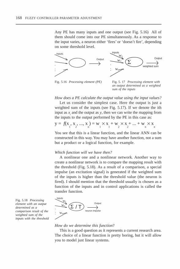
168 FUZZY CONTROLLER PARAMETER ADJUSTMENT
Any PE has many inputs and one output (see Fig. 5.16) All ofthem should come into our PE simultaneously. As a response tothe input varies, a neuron either ‘fires’ or ‘doesn’t fire’, dependingon some threshold level.
How does a PE calculate the output value using the input values?Let us consider the simplest case. Here the output is just a
weighted sum of the inputs (see Fig. 5.17). If we denote the ithinput as x
i and the output as y, then we can write the mapping from
the inputs to the output performed by the PE in this case as:
y = f(x1, x
2, ..., x
n) = w
1 × x
1 + w
2 × x
2+ ... + w
n × x
n
You see that this is a linear function, and the linear ANN can beconstructed in this way. You may have another function, not a sumbut a product or a logical function, for example.
Which function will we have then?A nonlinear one and a nonlinear network. Another way to
create a nonlinear network is to compare the mapping result withthe threshold (Fig. 5.18). As a result of a comparison, a specialimpulse (an excitation signal) is generated if the weighted sumof the inputs is higher than the threshold value (the neuron isfired). I should mention that the threshold usually is chosen as afunction of the inputs and in control applications is called thetransfer function.
How do we determine this function?This is a good question as it represents a current research area.
The choice of a linear function is pretty boring, but it will allowyou to model just linear systems.
.
..
Inputs
Output
.
..
Inputs
Output
Σw1
w2
wn
weighted sum
Fig. 5.16 Processing element (PE) Fig. 5. 17 Processing element withan output determined as a weightedsum of the inputs
.
..
Inputs
Output
Σw1
w2
wn
/ Tneuron impulse
Fig. 5.18 Processingelement with an outputdetermined as acomparison result of theweighted sum of theinputs with the threshold
CH5.PM5 6/12/97, 1:45 PM168

FUZZY CONTROLLER PARAMETER ADJUSTMENT 169
Why not choose just the threshold function as in Fig. 5.19a?We may have a lot of problems with this function because we
are not able to take the derivative from it near the transformationpoint. Learning methods based on a gradient descent includedifferentiating. That’s why some more complicated functionsgiven on Figs 5.20c and d are applied in modern ANNs.
The transfer function could be something as simple as 0. Theoutput then depends upon whether the result of the summation ispositive or negative. The network could output 1 and –1, or 1 and0, etc., and the transfer function would then be a ‘hard limiter’or ‘step’ function (Fig. 5.19a). It has only a binary output. Anothertype of transfer function is the threshold or ramping function (Fig.5.19b), which could mirror the input within a given range, sayfrom zero to one, but could operate as a hard limiter outside thatrange. It is a linear function that has been clipped to the minimumand maximum values, which then makes it nonlinear. Yet anotheroption would be a sigmoid or S-shaped curve (such as shown inFigs 5.19c and d). The curve approaches minimum and maximumvalues at the asymptotes.
That sounds pretty interesting but does not explain how an ANNcan be used for our purposes.
New effects appear when you connect PEs into a network andif we attach some local memory to our PE, we can store resultsof previous computations and modify the weights used as we goalong. This ability to change the weights allows a PE to modifyits behaviour in response to its inputs, or to ‘learn’. For example,suppose a network identifies a dog as ‘a cat’. On successiveiterations, connection weights that respond correctly to dogimages are strengthened, those that respond to other images, such
Fig. 5.19 Different waysto determine thethreshold (transfer)function
CH5.PM5 6/12/97, 1:45 PM169

170 FUZZY CONTROLLER PARAMETER ADJUSTMENT
as cat images, are weakened until they fall below the thresholdlevel. It is more complicated than just changing the weights fora dog recognition; the weights have to be adjusted so that allimages are correctly identified.
How can we connect PEs into a network?Any way. PEs are supposed to compose a layer, and layers are
connected together composing an ANN. Suppose we take oneprocessing element and combine it with other PEs to make a layerof these nodes. Inputs could be connected to many nodes withvarious weights, resulting in a series of outputs, one per node.
Since each PE is a non-linear block, such an arrangement of PEsresults in a highly non-linear network.
Carrying the design yet another step, we can interconnectseveral layers. The layer that receives the inputs is called the inputlayer. It typically performs no function other than buffering of theinput signal. The network outputs are generated from the outputlayer. Any other layers are called hidden layers because they areinternal to the network and have no direct contact with theexternal environment. Sometimes they are likened to a ‘black box’within a network system. But just because they are notimmediately visible doesn’t mean you cannot examine what goeson in those layers. There may be several hidden layers.
The connections are multiplied by the weights associated withthat particular node with which they interconnect. They conveyanalog values. Note that there are many more connections thannodes. The network is said to be fully connected if every outputfrom one layer is passed along to every node in the next layer.
Inputs OutputsInput layer Output layerHidden layer
Fig. 5.20 ANN structure
CH5.PM5 6/12/97, 1:45 PM170

FUZZY CONTROLLER PARAMETER ADJUSTMENT 171
.
..
Inputs OutputsInput layer Output layerHidden layer
5.3.3 ANN types
Can the nodes be connected in any way? Is any order necessary?It depends on the type of the particular network. Actually a lot
of different ANN have been proposed. Some of them are givenin Table 5.4. Sometimes it is very hard to answer even a simplequestion. Anyway we will try to give just a very generalclassification. On the basis of the connection types ANN can bedivided into feedforward and recurrent. If the output of each nodepropagates from the input side (left) to the output side (right)unanimously then the ANN is called feedforward (Fig. 5.21). Ifthere is any link between nodes directed from the right to the left,this ANN has a recurrent type (Fig. 5.22).
The life of any ANN includes two phases: learning andapplication. Before one starts applying an ANN, it should betrained. The training procedures are determined by a learningregime and can be quite different from each other.
Generally, the goal of a neural network is to modify theweights to minimise the response error. Nudge the weights in thedirection that will minimise the difference between the measuredand desired outputs. The technique for modifying weights in theappropriate direction and magnitude (called a credit assignmentproblem) eluded researchers for years. However, the recentdevelopment of the back propagation learning scheme has solvedthis problem. Since the advent of ‘back-prop’, neural networkshave enjoyed renewed emphasis and application.
Fig. 5.21 Afeedforward network
CH5.PM5 6/12/97, 1:45 PM171

172 FUZZY CONTROLLER PARAMETER ADJUSTMENT
Table 5.4
UNSUPERVISED LEARNING (i.e., without a ‘teacher’)
Feedback nets Additive Grossberg (AG) Shunting Grossberg (SG) Binary Adaptive Resonance Theory (ART1) Analog Adaptive Resonance Theory (ART2, ART2a) Discrete Hopfield (DH)
UNSUPERVISED LEARNING (i.e., without a ‘teacher’)
Feedback nets Continuous Hopfield (CH) Discrete Bidirectional Associative Memory (BAM) Temporal Associative Memory (TAM) Adaptive Bidirectional Associative Memory (ABAM) Kohonen Self-organising Map (SOM) Kohonen Topology-preserving Map (TPM)
Feedforward-only nets Learning Matrix (LM) Driver-reinforcement Learning (DR) Linear Associative Memory (LAM) Optimal Linear Associative Memory (OLAM) Sparse Distributed Associative Memory (SDM) Fuzzy Associative Memory (FAM) Counterpropagation (CPN)
SUPERVISED LEARNING (i.e., with a ‘teacher’)
Feedback nets Brain-State-in-a-Box (BSB) Fuzzy Cognitive Map (FCM) Boltzmann Machine (BM) Mean Field Annealing (MFT) Recurrent Cascade Correlation (RCC) Learning Vector Quantisation (LVQ)
Feedforward-only nets Perceptron Adaline, Madaline Backpropagation (BP) Cauchy Machine (CM) Adaptive Heuristic Critic (AHC) Time Delay Neural Network (TDNN) Associative Reward Penalty (ARP) Avalanche Matched Filter (AMF) Backpercolation (Perc) Artmap Adaptive Logic Network (ALN) Cascade Correlation (CasCor)
CH5.PM5 6/12/97, 1:45 PM172

FUZZY CONTROLLER PARAMETER ADJUSTMENT 173
How does this back propagation work?The method is based on an analysis of how a change in any
particular weight influences the output of the network. After suchanalysis is done, the designer understands how to change theweights to achieve the specified values for the outputs.
What does such analysis include?First of all, one must construct a chain similar to Fig. 5.23. This
chain examines the influence of any weight factor on the outputvalue and, hence, on the error value. We consider as an error thedifference between the actual output and the desired one.
Is this just the way for forward propagation?Yes it is. The way backward will include a definition of how
any particular weight factor should be changed to minimise theerror. Here one must go through these chains in a reverse order.The so-called ordered derivatives originating from ordinary partialderivatives, form a base of the process.
This process is a learning process, of which there are two types:supervised and unsupervised. In a supervised mode, the actual out-put of the ANN is compared with the desired output. The ANNmust be trained before it starts being used. In an unsupervisedmode, there are no external factors influencing weight adjustment.
I still do not completely understand.Neither do I. At present, this learning mode is not well
understood and is still a research subject. Generally, neuralnetworks can be considered as trainable dynamic systems where
.
..
Inputs OutputsInput layer Output layerHidden layer
Fig. 5.22 A recurrentnetwork
Change in the ⇒
weight factor⇒
Change in the
weight factornode with this
Change in the
output value ⇒Change in the
output errorFig. 5.23 ANN analysisalgorithm
CH5.PM5 6/12/97, 1:45 PM173

174 FUZZY CONTROLLER PARAMETER ADJUSTMENT
the learning, noise tolerance and generalisation abilities grow outof their network structures, their dynamics and their distributeddata representation.
5.3.4 ANN application in fuzzy controller design
We must come back to ANN application in fuzzy controllerdesign.
How are ANNs applied in fuzzy controller design?Once again by different ways. According to [Tak95] there are
three main approaches:
fuzzy systems where ANN learn the shape of the surface ofmembership functions, the rules and output membershipvalues;
fuzzy systems that are expressed in the form of ANN and aredesigned using a learning capability of the ANN;
fuzzy systems with ANN which are used to tune theparameters of the fuzzy controller as a design tool but not asa component of the final fuzzy system.
In the first two approaches, ANNs become a component of thewhole neuro-fuzzy system. In the first approach, an ANN isapplied directly to design nonlinear multidimensionalmembership functions, which partition an input space. In thisway, an ANN is utilised to conduct fuzzy reasoning [Tak91]. Therather famous ANFIS systems [Jang95] are an example of thesecond approach.
x x1 2
y r
wj
xhj
wi j
...
r
r
r
0
Fig. 5.24 A neuro-fuzzy controller Fig. 5.25 ANN for onerule implementing
CH5.PM5 6/12/97, 1:45 PM174

FUZZY CONTROLLER PARAMETER ADJUSTMENT 175
5.3.5 ANFIS architecture
Let us consider the example of a Sugeno fuzzy model given in[Jang95]. Here the ANN is used to realise fuzzy processing oftypical fuzzy rules like
If x1 is A
1 and x
2 is A
2 then y
1= w
1 × x
1 + w
2 × x
2 +
r
1
If x1 is B
1 and x
2 is B
2 then y
2 = v
1 × x
1 + v
2 × x
2 +
r
2.
To realise this processing, the ANN similar to Fig. 5.26 has beendeveloped.
The first layer is the membership layer. An output of any nodein this layer gives the membership degree of an input. The secondlayer is the multiplication layer. Every node here multiplies theinputs or membership degrees and produces the firing strength ofthe rule or the degree in which the corresponding rule is fired.
Why is multiplication applied? I understand that any t normoperation can be used.
You are absolutely right. Multiplication has been chosen in thisapplication to represent the t norm operation. The third layer is anormalising layer. It calculates a ratio of the particular rule-firingdegree to the sum of all rule degrees. The fourth layer is the outputcalculating one. Any node here is an adaptive node with the outputcalculated according to the formula:
f = V (w1 × x
1 + w
2 × x
2 +
r
1)
where V is the output of the third layer node and x1 and x
2 are the
inputs of the network.
Fig. 5.26 ANFISarchitecture
CH5.PM5 6/12/97, 1:45 PM175
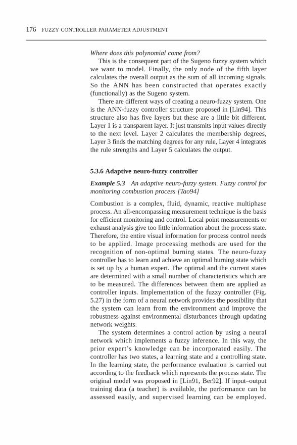
176 FUZZY CONTROLLER PARAMETER ADJUSTMENT
Where does this polynomial come from?This is the consequent part of the Sugeno fuzzy system which
we want to model. Finally, the only node of the fifth layercalculates the overall output as the sum of all incoming signals.So the ANN has been constructed that operates exactly(functionally) as the Sugeno system.
There are different ways of creating a neuro-fuzzy system. Oneis the ANN-fuzzy controller structure proposed in [Lin94]. Thisstructure also has five layers but these are a little bit different.Layer 1 is a transparent layer. It just transmits input values directlyto the next level. Layer 2 calculates the membership degrees,Layer 3 finds the matching degrees for any rule, Layer 4 integratesthe rule strengths and Layer 5 calculates the output.
5.3.6 Adaptive neuro-fuzzy controller
Example 5.3 An adaptive neuro-fuzzy system. Fuzzy control formonitoring combustion process [Tao94]
Combustion is a complex, fluid, dynamic, reactive multiphaseprocess. An all-encompassing measurement technique is the basisfor efficient monitoring and control. Local point measurements orexhaust analysis give too little information about the process state.Therefore, the entire visual information for process control needsto be applied. Image processing methods are used for therecognition of non-optimal burning states. The neuro-fuzzycontroller has to learn and achieve an optimal burning state whichis set up by a human expert. The optimal and the current statesare determined with a small number of characteristics which areto be measured. The differences between them are applied ascontroller inputs. Implementation of the fuzzy controller (Fig.5.27) in the form of a neural network provides the possibility thatthe system can learn from the environment and improve therobustness against environmental disturbances through updatingnetwork weights.
The system determines a control action by using a neuralnetwork which implements a fuzzy inference. In this way, theprior expert’s knowledge can be incorporated easily. Thecontroller has two states, a learning state and a controlling state.In the learning state, the performance evaluation is carried outaccording to the feedback which represents the process state. Theoriginal model was proposed in [Lin91, Ber92]. If input–outputtraining data (a teacher) is available, the performance can beassessed easily, and supervised learning can be employed.
CH5.PM5 6/12/97, 1:45 PM176

FUZZY CONTROLLER PARAMETER ADJUSTMENT 177
Otherwise, the performance evaluation only gives a reinforcementsignal where reinforcement learning can be applied. In thecontrolling state, the controller simply does fuzzy inferencewithout adjusting its parameters. The neural network consists ofa few layers. Nodes in Layer 1 are input nodes, representing inputlinguistic variables. They transmit sensor readings to the next layerwhich performs fuzzification. Nodes in Layer 3 are rule nodes andones in Layer 4 perform defuzzification.
5.3.7 Application examplesExample 5.4 Neuro-fuzzy controller for a washing machine[Tak95-2] (Matsushita Electric Group)
This model needs less water,energy and detergents, yet getsthe wash spotlessly clean.
Its features:
New ‘stains program’ foreffective, specific stainremoval.
Consumption: 50 litres ofwater and 1.7 kWh.
Sensor-controlled automaticdosing by fuzzy logic.
Fig. 5.27 Neuro-fuzzycontroller for combustionmonitoring
Fig. 5.28 ÖKOLAVAMAT 6955 sensorlogic washing machinefor stains
CH5.PM5 6/12/97, 1:45 PM177
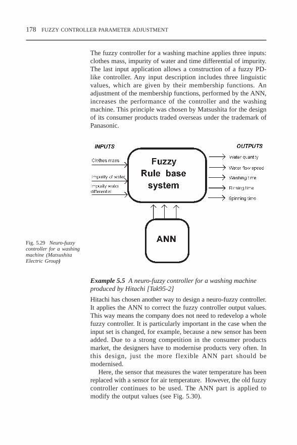
178 FUZZY CONTROLLER PARAMETER ADJUSTMENT
The fuzzy controller for a washing machine applies three inputs:clothes mass, impurity of water and time differential of impurity.The last input application allows a construction of a fuzzy PD-like controller. Any input description includes three linguisticvalues, which are given by their membership functions. Anadjustment of the membership functions, performed by the ANN,increases the performance of the controller and the washingmachine. This principle was chosen by Matsushita for the designof its consumer products traded overseas under the trademark ofPanasonic.
Example 5.5 A neuro-fuzzy controller for a washing machineproduced by Hitachi [Tak95-2]
Hitachi has chosen another way to design a neuro-fuzzy controller.It applies the ANN to correct the fuzzy controller output values.This way means the company does not need to redevelop a wholefuzzy controller. It is particularly important in the case when theinput set is changed, for example, because a new sensor has beenadded. Due to a strong competition in the consumer productsmarket, the designers have to modernise products very often. Inthis design, just the more flexible ANN part should bemodernised.
Here, the sensor that measures the water temperature has beenreplaced with a sensor for air temperature. However, the old fuzzycontroller continues to be used. The ANN part is applied tomodify the output values (see Fig. 5.30).
Fig. 5.29 Neuro-fuzzycontroller for a washingmachine (MatsushitaElectric Group)
CH5.PM5 6/12/97, 1:45 PM178

FUZZY CONTROLLER PARAMETER ADJUSTMENT 179
INPUTS
Clothes mass
Clothes quality
Water temperature
OUTPUTS
Water quantity
Water flow speed
Washing time
Rinsing time
Spinning time
Clothes mass
Clothes quality
Air temperature
Correctingvalues
FuzzyRule base
system
ANNFig. 5.30 Neuro-fuzzycontroller for a washingmachine (Hitachi)
I understand that fuzzy logic and ANN work simultaneously orin parallel. It saves a lot of time.
Right. It did in these examples but generally it doesn’t have to.
Example 5.6 Sanyo rotating electric fan.
This fan should rotate itself towards the user. The user’s positionis identified by a remote control signal origin. The fan has threeinfrared sensors where the signals are used to calculate a distanceto the user using a fuzzy system. Then this distance and the ratiosof sensor outputs are used by an ANN to compute the fandirection (Fig. 5.31). This combination has allowed significantimprovement in the quality of a distance calculation.
INPUTS
mid(L,R,C)
max(L,R,C)
Angle estimate
min( C/C+L, C/C+R)
ANN
FuzzyRule base
system
Fig. 5.31 A neuro-fuzzycontroller for a rotatingfan
CH5.PM5 6/12/97, 1:46 PM179

180 FUZZY CONTROLLER PARAMETER ADJUSTMENT
5.4 Adjustment procedures with genetic/evolutionaryalgorithms
5.4.1 How does it work?
Another technique which is used in fuzzy controller design andwhich was inspired by biology is genetic algorithms.
We have just finished with artificial neurones. What do we needthese genetic algorithms for? Isn’t ANN enough?
ANN represent a great method but it has its limitations, ofcourse. Before applying, any ANN should be trained. Training isperformed with a presentation of the sampling data. In some cases,several thousands data examples may be required to be presentedin a randomised order, and the learning techniques often demandhuman supervision to guarantee convergence [Link95]. So theapplication of ANN may require a high computational power anda long period for training, which are not available in some controlapplications. There is a need to optimise the training process, andgenetic algorithms (GA) application is one of these ways.
Explain about genetic algorithms.The GA method imitates natural evolution processes, and hence
includes operations such as reproduction, crossover and mutation.A conventional GA has four main features: population size,reproduction, crossover and mutation. Reproduction is a processin which a new generation of population is formed by thestochastic selection of individuals from an existing population,based on their fitness.
This process results in individuals with higher fitness valuesbeing more prevalent in the next generation, while low fitnessindividuals are less so; for this reason it is sometimes referred toas a ‘survival of the fittest’ test. Crossover is perhaps the mostdominant operator in most GAs, and is responsible for producingnew trial solutions on-line. Under this operation, two individualsare selected to produce new offspring by exchanging portions oftheir structures. These offspring may then replace the existingtrials. Mutation is a localised, bitwise operator, which is appliedwith a very low probability, typically 0.001 per bit or less. Its roleis to alter the value of a random position in a gene-string. Whenused in this way, together with the other operators, reproductionand crossover, mutation acts as an insurance against total loss ofany genes in the population, by its ability to introduce a gene
CH5.PM5 6/12/97, 1:46 PM180

FUZZY CONTROLLER PARAMETER ADJUSTMENT 181
which may not, initially, have existed or was lost in the courseof application of other operators.
For a given population of trials and set of operators, together withthe evaluation function, a typical GA proceeds as follows:
an initial random population of trials, Π(0) = An(0), n = 1,...,N,
where N is the population size, is generated; for successive sample instances t, the performance of each trial,
µ (An(t)),t = 0,1,2,..., is evaluated and stored;
one or more trials are selected to produce offspring by takinga sample of Π(t) using the probability distribution:ρ (A
n(t)) = µ (A
n(t))/Σ µ (A
i(t))
one or more of the genetic operators are applied to the selectedtrials in order to produce new offspring, A°
m (T), m = 1,..., M,
where M is the number of offspring, which is usually equal tothe number of selected parent trials;
the next generation of population, Π(t + 1) is formed byselecting A
i(t) ∈ Π(t), i = 1, ..., M to be replaced by the
offspring, Aj(t), j = 1 – M. The criterion for selecting which
trials should be replaced may be random, on the basis of theleast fit or some other fitness basis;
the GA process is terminated after a pre-specified number ofgenerations or on the basis of a criterion which determinesconvergence of the population.
Fig. 5.32 Geneticalgorithm procedure
CH5.PM5 6/12/97, 1:46 PM181
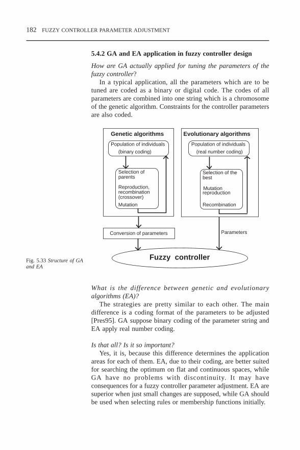
182 FUZZY CONTROLLER PARAMETER ADJUSTMENT
5.4.2 GA and EA application in fuzzy controller design
How are GA actually applied for tuning the parameters of thefuzzy controller?
In a typical application, all the parameters which are to betuned are coded as a binary or digital code. The codes of allparameters are combined into one string which is a chromosomeof the genetic algorithm. Constraints for the controller parametersare also coded.
What is the difference between genetic and evolutionaryalgorithms (EA)?
The strategies are pretty similar to each other. The maindifference is a coding format of the parameters to be adjusted[Pres95]. GA suppose binary coding of the parameter string andEA apply real number coding.
Is that all? Is it so important?Yes, it is, because this difference determines the application
areas for each of them. EA, due to their coding, are better suitedfor searching the optimum on flat and continuous spaces, whileGA have no problems with discontinuity. It may haveconsequences for a fuzzy controller parameter adjustment. EA aresuperior when just small changes are supposed, while GA shouldbe used when selecting rules or membership functions initially.
Genetic algorithms Evolutionary algorithms
Population of individuals
(binary coding)
Population of individuals
(real number coding)
Selection ofparents
Reproduction,recombination(crossover)
Mutation
Selection of thebest
reproductionMutation
Recombination
Conversion of parameters
Fuzzy controller
Parameters
Fig. 5.33 Structure of GAand EA
CH5.PM5 6/12/97, 1:46 PM182

FUZZY CONTROLLER PARAMETER ADJUSTMENT 183
How do these algorithms work in fuzzy controller design?Let us consider the process in greater detail following
[Huang95]. GA have been widely applied for the membershipfunction adjustment. One can adjust the shape of membershipfunctions or parameters of the shape selected. For example, if thetriangular function has been chosen, the set of three parametershas to be evaluated. As the parameters of not one but a fewmembership functions are to be determined, all of them areconcatenated as a string. This string is then encoded. The numberof bits (or digits) in a code string determines the length of achromosome – the parameter of GA.
Let us consider the operation with GA in greater detail, stepby step (see Fig. 5.32). On the first step, a random numbergenerator is applied to generate individuals – chromosomes. Onthe second step, the fitness of each chromosome is evaluated. Thepredetermined fitness function is used here to calculate how goodthe chromosome is. Criteria traditionally applied in controlengineering can be utilised here as a fitness function, for example,the error signal. One has to remember, however, that the highervalue of the fitness function should correspond to the betterchromosome. So the error signal can be applied directly as afitness function but should be converted. In the case of the errorthe fitness function could be chosen as e ke− where k is a positivenumber and e is the error value.
At the next step the process of a parent selection is conducted.This process is similar to a spin of a roulette wheel. The selectionalgorithm is implemented based on the computed fitness ofindividuals. A new population pool is formed by several spins ofa roulette wheel. Since the slot size is made to be proportional tothe individual’s fitness, most of the selected parents come to thenew population pool with a higher fitness. Although the averagefitness in the new pool is higher than in the original pool, someindividuals may have the lower fitness. A pair of parents are thenselected from this new pool for a further genetic operation.
The next step is the stage for a crossover and mutation process.A crossover point along the chromosome is randomly selected.A part of the genes on one side of this point is given to the child.The rest of the child’s genes come from the same side of the otherparent. Mutation plays a vital role in genetic optimisation as itintroduces new genetic material that was lost by chance throughpoor selection of mates. However, one must be careful, as theoveruse of mutation may distract a good chromosome in the nextgeneration. The probability of mutation must be small enough to
CH5.PM5 6/12/97, 1:46 PM183

184 FUZZY CONTROLLER PARAMETER ADJUSTMENT
avoid degenerating the performance [Krist92]. So the mutationrate is usually selected to be about 0.0001–0.01. The number ofindividuals in each generation (the population size) is chosen onthe base of the experiments. All the individuals in each generationhave to be evaluated. One should understand that a large size maycause a long operation time. So usually the operation size ischosen between 50 and 500.
5.4.3 Application example
Example 5.7 Membership functions adjustment in aircraft flightcontrol [Bour 96]
Let us consider an adjustment of the membership functions forthe fuzzy controller given in Example 3.5. The triangularmembership functions are applied to describe input and outputvariables. There are two ways to achieve optimal membershipfunctions: choose the entire membership functions as variables to be
optimised; only choose the overlaps between membership functions as
variables to be optimised.
We use the first method for the optimisation procedure. In thiscase, the triangle membership functions can have a variable widthand be shifted along the x axis. This is the method of choosingall the points of the triangle shapes of the membership functionsand moving these points along the x axis (as long as they do notexceed the upper and lower limits of the universe of discourse)until efficient membership functions are found. The triangles canchange their variable base. Therefore, each triangle requires thedefinition of only one point to fix it. The entire set of fuzzymembership functions for a fuzzy controller must be representedas a binary string (of 0 and 1). To do this, the best choice is touse binary coding.
To apply GA, one needs initially to perform the followingprocedures
Parameter coding: translate the fuzzy membership functionsinto strings.
Initial generation: generate an initial population of 50 stringsby using random numbers.
Fitness function: decode each string into a set of actualparameters as membership functions and calculate the fitnessvalue of each set by simulation.
CH5.PM5 6/12/97, 1:46 PM184

FUZZY CONTROLLER PARAMETER ADJUSTMENT 185
The bit strings, representing the overlapping parameters, must thenbe judged and assigned a fitness value, which is a scorerepresenting a degree to which they accomplished the goal ofdefining high performance. However, the definition of the fitnessfunction, that enables the GA to locate high performance andefficient membership functions, is application dependent. Theperformance index of the ith string (or the ith membershipfunction) is defined as a trajectory length which is required toreach the goal point.
Selection: copy strings into the mating pool according to theirfitness value.
Reproduction: copy strings with better fitness values into anew generation. We assume that the best 10 per cent of thegeneration of the size of 50 can be copied into the newgeneration.
Generation of new strings: generate 90 per cent of 50 stringsinto a new generation.
Crossover: select pairs of strings from the mating pool andexchange their corresponding portions of a string at a randomlyselected position. The crossover probability of 0.8 is taken forsimulations.
Mutation: alternate the value of the randomly selected integerbyte, this value may be changed into any number. The mutationprobability of 0.1 is supposed.
Iteration: repeat the process from the fitness functioncalculation to mutation until it reaches the predeterminedending condition.
CH5.PM5 6/12/97, 1:46 PM185

186 FUZZY CONTROLLER PARAMETER ADJUSTMENT
CH5.PM5 6/12/97, 1:46 PM186

FUZZY SYSTEM DESIGN SOFTWARE TOOLS 187
6 FUZZY SYSTEM DESIGNSOFTWARE TOOLS
6.1 Fuzzy technology products classificationA fast-growing information technology industry has alreadydeveloped and released about a dozen good design packageswhich are successfully used in different applications for fuzzycontroller design. Among them are: RT/FuzzyTM Toolbox forMATRIXxTM by Integrated Systems Inc., Fuzzy Logic Toolboxfor MATLABTM by The MathWorks Inc., FIDETM by Aptronix,fuzzyTECHTM by Inform, a number of products by TogaiInfraLogic Inc., Fuzzy Systems Engineering Inc., HyperLogic,etc. Some of them are specific for a fuzzy technology, others areuniversal and include a special fuzzy design toolbox. Theseproducts started appearing on the market in the late 1980s andearly 1990s.
Table 6.1
Company Products
Aptronix (USA) FIDEBell Helicopter Textron (USA) FULDEKByte Craft (Canada) Fuzz-CCICS Automation (Australia) Fuzzy Control Toolbox for UNACFuzzy Systems Engineering (USA) Fuzzy Knowledge Builder, Fuzzy
Decision Maker, and FuzzyThought Amplifier
FUZZYSOFT AG and GTS FS-FUZZYSOFTTrautzel GmbH (Germany)
FuzyWare (USA) FuziCalcHIWARE (Switzerland) HI-FLAGHyperLogic (USA) CubiCalc, CubiCalc RTC, CubiCalc
RuleMaker, CubiCard, andCubiQuick
Inform (Germany) fuzzyTECHIntegrated Systems (USA) RT/Fuzzy in MATRIXxIntelligent Machines (USA) O INCAKentRidge Instruments (Singapore) FlexControlManagement Intelligenter DataEngine
Technologien (MIT)GmbH (Germany)
The MathWorks (USA) Fuzzy Logic Tool Box for MatLab
CH6.PM5 6/12/97, 1:59 PM187

188 FUZZY SYSTEM DESIGN SOFTWARE TOOLS
Table 6.1 (continued)
Company Products
MentaLogic Systems (Canada) Quick-Fuzz, Auto-Fuzz, Multi-Fuzz,Flex-Fuzz, Process-Fuzz, AutoSim-Fuzz, Fuzz-Drive, F-MTOS,CT-FLC
Metus Systems (USA) FuzzySPMODICO (USA) FUZZLENational Semiconductor (USA) NeuFuzNicesoft (USA) Decision PlusTexas A&M University (USA) FL ControlTogai InfraLogic (USA) TILShell+ and other productsUniversity of New Mexico (USA) Fuzzy logic Code Generator (FLCG)
The availability of the products on the market as well as their pricemeans that we will not include in this text any homemade softwaretools for fuzzy controller design. Certainly, the main advice is touse one of these packages. The purpose of this chapter is to
Fig. 6.1 Classification offuzzy system design tools
CH6.PM5 6/12/97, 1:59 PM188

FUZZY SYSTEM DESIGN SOFTWARE TOOLS 189
illustrate how. We will consider the features of the packages andgive some examples of their applications. The main differencefrom other references available at the moment is that we try notto describe different packages but to point out some their commonand specific features. This is the only way to preserve the valueof this text for some time, at least. For more detail see theinformation booklets issued by companies, as well as an excellentsurvey in [Chiu95].
Table 6.1 contains the names of the some companies thatproduce fuzzy products. Please note that not all of these productsand even companies are currently on the market. This table wascompiled from different sources including [Chiu95, Jam94]. Thetrademarks given in the right-hand column of Table 6.1 areregistered with the corresponding companies in the left-handcolumn. A little more detailed information about the companiesincluding their addresses and some characteristics of their productsis provided in Table 8.6.
Let us look at the different types of fuzzy products availablenowadays (Fig. 6.1). Software tools for fuzzy system analysis(FuzzyCalcTM, CubiCalcTM, etc.) were historically the firstgeneration of the products on the market. They were produced bysmall innovative companies. After that, companies producinggeneral-purpose simulation and design tools (MATRIXxTM, etc.)introduced fuzzy parts into their packages. One should note thatdespite the availability of universal fuzzy design software, manycompanies have chosen to invest money and time in thedevelopment of specialised, in-house fuzzy logic design tools.Companies such as Motorola, Intel, Siemens, SGS-Thomson,Texas Instruments and Hitachi have demanded customisationfrom the providers of commercial fuzzy tools because the off-the-shelf products were inadequate for their requirements.Similarly, National Semiconductor built its own in-house fuzzysoftware product to aid in the design and implementation of theirsemiconductor chips. This generation of commercial fuzzy logicdesign products had a limited aim: the design of simple controlsystems for specialised embedded microprocessors.
The list of the products and the review following in thischapter refer mainly to the universal design packages, that is,software tools which can be applied for different designs andwhich are not oriented towards use on a particular hardwareplatform. The most common features of the packages availableare considered and illustrated with some examples in thefollowing sections.
CH6.PM5 6/12/97, 1:59 PM189

190 FUZZY SYSTEM DESIGN SOFTWARE TOOLS
6.2 Main features of the fuzzy software toolsThe goals of the design package are usually:
speeding up a design process; making the design simple, user friendly and attainable; providing the possibility to apply fuzzy logic and control
methods without a deep understanding of how they work.
Applications are often universal and can be applied in expertsystems as well as control system design; only a few target controlapplications and control system design.
It is important to provide good service, pre- and after-salecustomer support, and continuous improvement and developmentof the products.
The basic description and programming language is an object-oriented high level language that provides connections and linksto other design tools, programming and simulation environment(e.g. FTLTM by Inform Software).
In order to achieve multisystem realisation, different versionsare usually available for MS-WindowsTM, UNIXTM , and VMETM
operating system environments.A design package often includes other intelligent technology
tools, first of all neural networks, and the option to integratethem with fuzzy design tools in order to improve and evenoptimise a design (e.g. Neural Networks toolbox in MatlabTM,NeuroFuzzyTM module in fuzzyTECHTM).
The package includes automation tools for all life phases ofthe product development, from design to implementation throughsimulation, debugging, optimisation for a target platform andverification. It supports a design environment where a designerdoes not have to write a single line of programming code.
The design package is almost always accompanied by theeducational tools provided by the manufacturer. These tools canbe used for learning the fundamentals of fuzzy logic and control,as well as for acquiring basic knowledge about using andapplying this particular package. The tools can be provided asa written tutorial (Togai InfraLogic) or even as a computereducational kit (Fuzzy Logic Educational program byfuzzyTECHTM Explorer).
It supports an advanced man–machine graphical interfaceincluding all-graphical editors for different elements of fuzzysystems and other systems in all design phases. Also, it usuallyprovides a user-friendly interface for any level user, sometimes
CH6.PM5 6/12/97, 1:59 PM190

FUZZY SYSTEM DESIGN SOFTWARE TOOLS 191
with the possibility of producing an executable program codewithout any programming.
Different methods of fuzzy processing are supported, shapesof membership functions, fuzzification and defuzzificationmethods, etc., providing a user with many choices
The package is able to generate a portable C-code (almost allpackages) and/or source codes oriented to different types ofmicroprocessors, programmable controllers, etc. The type of codegenerated can be a main factor in choosing between the systems.They can interface with a large number of other general designtools such as MATLABTM, MS-ExcelTM, etc. Systems are oftensupplied in a package with the hardware products (differentproducts have this option in various degrees from a board to aspecial control unit).
Many of the companies producing fuzzy design tools originatefrom university research and were founded by distinguishedfuzzy logic and control academics and scholars (Zimmermann,Jamshidi, Goodwin, Welstead).
6.3 Realisation examplesThe examples following illustrate different features of the designpackages and give some more information about them.
Example 6.1 Support of the entire development process includingsystem analysis of the problem – FS-FUZZYSOFT designenvironment (Fig. 6.2)
The first step in the design of a fuzzy-based system is an analysisof the problem. This results in a basic system outline structure,and includes its inputs and outputs. The specific knowledge of thesystem has to be described by means of linguistic variables andfuzzy rules. During an implementation of the project, severaloperators and parameters have to be defined, such as a fuzzy-specific inference method, or an internal resolution (to investigatesystem behaviour when implemented as a microcontroller withlimited data resolution, e.g., only 8-bit data, no floating pointhardware).
For the system test, simulation can be done by applying varioussignals, either in a closed loop, together with a model, or finally,on-line at the real process. An optimisation is done interactively,by use of the various sophisticated debugging tools. As the finalstep in the design of a fuzzy system, the system is implemented,either by generating the C-code or the code for a specificmicrocontroller.
CH6.PM5 6/12/97, 1:59 PM191

192 FUZZY SYSTEM DESIGN SOFTWARE TOOLS
Example 6.2 Incorporation of the fuzzy system block intomodelling and simulation environment – RT/FuzzyTM block inMATRIXxTM
The RT/Fuzzy block has been developed mainly for controlapplications. It is constructed as just one of the blocks amongothers to model and simulate a control system in the specialenvironment called SystemBuildTM. RT/Fuzzy has become anelement of the library which includes linear dynamic systems,nonlinear elements, signal generators, mathematical functionsand signal junctions. This is particularly convenient for rapidprototyping. The modularity principle is applied to theconstruction of the block itself as well. Any particular block canbe accessed by clicking a corresponding icon. The rapidprototyping is highly recommended by the software authors asthe method for applying fuzzy logic to describe parts of thewhole system that are not yet fully understood. So it allows anapproximation of the system behaviour with a fuzzy logicmodel.
The fuzzy block itself contains the rules and the data about theinputs and outputs. A user has an opportunity to enter differentrules and data, change and edit them. User-definable functionality
Fig. 6.2 The structure ofthe FS-FUZZYSOFT toolsfor design support
CH6.PM5 6/12/97, 1:59 PM192

FUZZY SYSTEM DESIGN SOFTWARE TOOLS 193
generally is one of the construction principles of these packages.To define the fuzzy system, a user has to fill in a set of specialforms interconnected to each other.
After the design is completed, the fuzzy controller becomesjust one of the blocks in the entire model. Examples of suchmodels are seen in Figs. 4.1 and 5.6.
Example 6.3 User education with specially provided teachingtools – Fuzzy Logic Computer educational kit by Aptronix.
This kit accompanies the FIDETM design package but is availableseparately. It presents, in an interactive mode, basic knowledge infuzzy theory, fuzzy system analysis and design. It includes somecomputer-based tutorials covering fuzzy logic theoreticalfundamentals and fuzzy technology. The kit contains informationabout main applications and requires the user to design simplesystems. It also includes a number of self-assessment questionsto test understanding.
The first part of the kit presents the mathematical fundamentalsof the fuzzy logic and fuzzy sets theory. The presentation is builtas a comparison between crisp (classical) sets and fuzzy sets,classical logic operations and fuzzy logic operations. Thisconstruction allows the user both to use his or her knowledge ofclassical mathematics in learning new theory and to refamiliarisethe user with classical set and logic theory. Then come thechapters specifically for fuzzy logic. The first part serves as thetheoretical introduction for solving application problems,particularly problems of fuzzy control.
The main part of the kit is occupied by fuzzy control problems.Because of the practical orientation, the main domain in this partis devoted to the design of fuzzy logic controllers. It incorporatesthe manuals on FIDE fuzzy products and their application in fuzzycontroller design.
The kit runs under MS-Windows. The computer realisationprovides:
an interaction between the user and a computer; a graphical presentation of educational materials; a simple menu-driven control of the computer session, with an
adaptation to the user’s level.
Example 6.4 High-level object oriented programming languagefor design and development, – the TIL Fuzzy ProgrammingLanguageTM (FPL) by Togai InfraLogic
CH6.PM5 6/12/97, 1:59 PM193

194 FUZZY SYSTEM DESIGN SOFTWARE TOOLS
The TIL FPL is specifically designed for the implementation offuzzy knowledge bases. Programming consists of combiningspecial language objects. There are nine special objects: project,package, source, fuzzy, var, connect, rule, fragment and member.As there are special hierarchical relationships between differentobjects (see Fig. 6.3), specific rules are applied, where an objectcan be defined.
The project object is the top level object. There should be onlyone project in the file, which contains information necessary todefine a fuzzy system. The package object can be applied todivide a fuzzy system into subsystems and to create a hierarchicalstructure. This object is used to describe a part. Fuzzy objectsdefine fuzzy rule bases and rules objects define rules. To embedsource codes into rules bases, fragment objects are applied. Varobjects correspond to the variables in conventional programminglanguages. Member objects are used to define membershipfunctions.
Example 6.5 Inclusion of software tools for all life stages of thedesign: from the project description to implementation – FIDETM
by Aptronix
FIDE (Fuzzy Inference Development Environment) integratessystem design, tuning and simulation of a fuzzy system tools.FIDE tools work on two levels: FIDE inference unit (FIU) designand an overall system design.
To develop a FIU one has to: create and edit a FIU; debug, tune and simulate; generate a real-time code (for single FIU applications).
Fig. 6.3 FPL objectstructure
Project
Package
Source Fuzzy Var Connect
Fragment Rule Member
CH6.PM5 6/12/97, 1:59 PM194

FUZZY SYSTEM DESIGN SOFTWARE TOOLS 195
To design the whole system one may:
graphically link FIUs and conventional execution units; debug and tune an overall system; make an overall system host executable code; run the overall system simulation while tuning FIUs; generate a real-time code for each FIU.
At the unit level, a single FIU is developed by specifying themembership functions and writing the rules. Optionally, one candevelop a system for an application. The system level mayconsist of multiple inference units and conventional executionunits. FIDE links previously compiled and tested FIUs and non-fuzzy units into a coherent whole design.
Example 6.6 User-friendly design and advanced graphicalinterface – CubiCalcTM
CubiCalc provides a text editor for entering the rules as if–thenstatements and a graphic point-and-click editor for definingmembership functions as connected line segments. Rule weightsand linguistic hedges are supported. Rule weights can be enteredby a user interactively or from other modules. While defining amembership function, the editor first presents a simple shapeformed by a few connected vertices. A user can reshape themembership function by moving the vertices with the mouse oradd new vertices to create a more complex shape.
Any variable available to CubiCalc can be plotted on a two-dimensional scrolling strip chart, a scatter chart or a polar plot.The output membership functions can also be displayed. A three-dimensional plot of the decision surface can also be presentedto a viewer. CubiCalc can be used to view a surface plot withany variable as a function of two others.
Example 6.7 New ‘clicking mouse’ technology of programmingand software design with an ability of producing an executablesoftware without knowing any programming language orcompiling any program segments – FUZZLETM
FUZZLE software is fully supported with graphics displays andmouse functions. One of the outputs is a source code in C orFORTRAN language that can be converted into an executablecode and attached to an application environment. In addition,FUZZLE has its own execution module with graphics supportwhich does not require any programming, compilation or linking.
CH6.PM5 6/12/97, 1:59 PM195

196 FUZZY SYSTEM DESIGN SOFTWARE TOOLS
Fig. 6.4 FUZZLEoperational environment
Using this option, the user can obtain inference results directlyfrom the FUZZLE shell by entering data via keyboard or externaldata files. Once the inference engine is validated, the executableportion of the software can be extracted by a click of a button,and it can be customised for special purpose applications. Thefinal product, which is stripped from FUZZLE related functionsand screen images, is ready for distribution and it is royalty-free.
Example 6.8 Producing an output code oriented on differenthardware implementation – fuzzyTECHTM
To satisfy any user, different fuzzyTECH versions may includetranslators which produce an output file in C, an assembly codefor INFORM’s FUZZY-166 fuzzy processor, an assembly code forvarious Intel, SGS-Thomson, and Siemens microcontrollers, or acode for programmable logic controllers (PLC) produced byAllen-Bradley, Siemens and Klockner-Moeller. Users aresupposed to purchase the different versions of fuzzyTECHdepending on the type of the code they wish to generate.
Example 6.9 Advanced simulation and debugging support –FIDETM
FIDE provides tools for simulation and debugging separate FIUsas well as an entire system. One can debug a FIU using MF-Edit,Analyser, Tracer and Simulator.
CH6.PM5 6/12/97, 1:59 PM196

FUZZY SYSTEM DESIGN SOFTWARE TOOLS 197
MF-Edit – graphically modifies membership functions. Onemay edit membership functions by modifying the FIL sourcecode. However, it may be more convenient to tunemembership functions graphically. The Membership FunctionEditor (MF-Edit) graphically defines new shapes formembership functions and saves the results in files (if possibleto edit).
Analyser – provides a three-dimensional view of the responsefunction, it can also trace back to the source code for anyanomaly point.
Tracer – provides the user with an ability for given inputvalues to inspect the output, inference process step by step,and trace back to the source code. Tracer is used to trackspecific FIU behaviour to the actual rules. Tracer alsoprovides a detailed look at every step of the inference process.One can follow an execution from the output directly backto the rule base in the source code. The anomalies areapparent which should be addressed in the debuggingprocess.
Simulator – allows a user to view input and output valuesgraphically as a function of time (steps). The simulation isdriven by a set of input values which are specified by the userin a separate file. If the resulting response functions exhibitundesirable behaviour (such as the overshoot, for example), therules and membership functions that cause this behaviour canbe directly determined with Tracer, and then the FIL sourcecode is recompiled.
These tools are used to identify and correct errors in source codes.Also, one can fine-tune one’s application with other debuggingtools. The Composer is a text and graphic editor used to linkFEUs, FIUs and FOUs and then interconnect them. It can alsobe used to illustrate data flow graphically through the overallsystem and locate errors which may not be apparent until theentire system is analysed.
All debug utilities are able easily to identify rules andmembership functions that require modification. Rule modi-fication is accomplished using FIL editor. Membership func-tion modification can use FIL editor or the graphical MF-Editfeature. Once changes are made, the FIU can be recompiledand the debug process can start again. The real-time code(RTC) option on the FIDE menu allows one to generate as-sembly code versions of one’s FIU for various Motorolamicroprocessors.
CH6.PM5 6/12/97, 1:59 PM197

198 FUZZY SYSTEM DESIGN SOFTWARE TOOLS
Example 6.10 Combining abilities with other intelligent tools –NeuroFuzzyTM Module in fuzzyTECHTM
In many applications, the desired system behaviour is representedby data sets. In control systems, these data sets may representoperational states. The NeuroFuzzy Module allows us to use thesedata sets for an automated fuzzy controller adjustment with anyfuzzyTECH edition. An adjustment of both membership functionsand fuzzy rules is supported as well as an automatic optimisationtowards the data sets. The NeuroFuzzy Module (Fig. 6.5)integrates neural network technologies to train fuzzy logicsystems. In contrast to conventional neural network solutions, theentire training process and the resulting fuzzy logic systemremain completely self-explanatory.
The training technology used is based on a fuzzy logicinference extension that is implemented in most fuzzyTECHTM
editions: the use of Fuzzy Associative Maps (FAM). Such FAMrules can be considered generalised neurones and by using theNeuroFuzzy Module technologies, neural net training methodsare applicable. A fuzzy logic system generator optionally sets upappropriate membership functions and rule blocks prior to theactual training phase based on the data sets.
The NeuroFuzzy Module can also be used to optimise existingfuzzy logic systems. Starting with an existing system, theNeuroFuzzy Module interactively tunes rule weights andmembership function definitions, so that the system converges tothe behaviour represented by the data sets. Any fuzzy logic systemgenerated by the NeuroFuzzy Module can be optimised manuallyand verified.
Fig. 6.5 Neuro-FuzzyModule structure
CH6.PM5 6/12/97, 1:59 PM198

FUZZY SYSTEM DESIGN SOFTWARE TOOLS 199
Example 6.11 Including hardware blocks together with thesoftware tools to generate, model and simulate fuzzy controllerwith the embedded code – Fuzzy Microcontroller DevelopmentSystem by MentaLogic Systems Inc.
The automated fuzzy controller design station (see Fig. 6.6)includes the fuzzy expert system, AutoFuzz, for generation andoptimisation of automatic fuzzy rules and membership functions.It includes the FlexFuzzTM HPC1600 block for control modellingand a special evaluation board for chip development.
Example 6.12 Integration of software and hardware tools into aunited complex for design, simulation and real-time control –UNACTM
UNAC comprises two main components, GIACTM and SAACTM.GIAC (Graphical Interface for Advanced Control) is a softwarepackage running on a host computer, usually a workstation or PC.It provides a graphical user interface for operating UNAC. SAAC(Stand-Alone Advanced controller) is a hardware unit whichcommunicates with the host computer via both serial or Ethernetlinks. SAAC also communicates with the sensors and actuators ofthe process being controlled, via industry-standard links.
So UNAC is an integrated complex (see Fig. 6.7), combiningsoftware and hardware components, with a fuzzy control toolboxbeing just a part of its software half. The hardware part (SAAC)
Fig. 6.6 The structure forthe design anddevelopment system
CH6.PM5 6/12/97, 1:59 PM199

200 FUZZY SYSTEM DESIGN SOFTWARE TOOLS
Fig. 6.7 The integrationcomplex structure
Data Acquisition Data Preprocessing
Data Presentation
DataEngine VI
LabVIEW
is applied to acquire information from a plant. This data is usedto develop a dynamic model of the process, from which the block-diagram schematic is derived. Using the dynamic model, adesigner synthesises a control strategy for the process control, andtests it by simulation. After the model and control are verified, thecontrol program is downloaded into the hardware and applied foractual control.
Example 6.13 Integration and close interaction with otherdevelopment tools and environments – DataEngineTM
DataEngine has been developed as the product which containsdifferent tools for solving complex data analysis problems[Ang95]. The main members of this family are:
DataEngine – development tools for data analysis; DataEngine ADL – C++ library for the integration of data
analysis solutions in an existing software environment; DataEngine VI – virtual instruments for LabVIEW.
DataEngine VI incorporates the so-called Virtual Instruments totrain and run neuro-fuzzy systems under the environment ofLabVIEW®. So this product plays the role of an extra add-onlibrary for LabVIEW® which enables an automation ofclassification and pattern recognition problems. The relationshipbetween DataEngine VI and LabVIEW® is illustrated in Fig. 6.8[Ang95].
Fig. 6.8 Integration ofDataEngine VI with theLabVIEW products
CH6.PM5 6/12/97, 1:59 PM200

FUZZY CONTROLLER IMPLEMENTATION 201
7 FUZZY CONTROLLERIMPLEMENTATION
7.1 How do we implement a fuzzy controller?This chapter describes the hardware implementation of fuzzycontrollers. It gives some advice on how to construct real fuzzycontrollers. This is the most exciting part of such a developingarea as a fuzzy controller design and implementation. New chipsand devices are being developed and manufactured now in largequantities and any particular device will become obsolete beforethis book is read. So this chapter is short and filled with onlygeneral descriptions and recommendations.
The simplest and the most usual way to implement a fuzzycontroller is to realise it as a computer program on a generalpurpose processor. However, a large number of fuzzy controlapplications require a real-time operation to interface high-speedexternal devices. For example, automobile speed control, electricmotor control robot control are characterised by severe speedconstraints. Software implementation of fuzzy logic on generalpurpose processors cannot be considered as a suitable designsolution for this type of application. In such cases, designspecifications can be matched by specialised fuzzy processors.
The requirements to the hardware implementation are:
high-speed performance; low complexity; high flexibility.
These conditions contradict each other. So it is not easy to choose theright way, especially if one takes into account some other factors, suchas manufacturing cost (very important for consumer product fuzzycontrollers) or design cost (important in research and development).
I understand what one needs high performance for. What does lowcomplexity mean with regard to the hardware implementation?And high flexibility?
Low complexity means that algorithms for fuzzy processing,fuzzification and defuzzification have to be very simple and
CH7.PM5 6/18/97, 8:19 AM201

202 FUZZY CONTROLLER IMPLEMENTATION
demand as small an amount of memory as possible for theirrealisation. Flexibility means the ability of the hardware to be usedsuccessfully in different applications and configurations.
Considering these requirements, have any devices beendeveloped yet?
During recent years, there has been an increasing interest inthe development of an efficient fuzzy controller hardwarecapable of coping with the requirements of real-time applications.Togai and Watanabe [Tog86] developed the first fuzzy logic chipin 1985. Later Yamakawa developed a fuzzy logic hardware usinganalog techniques. Since then, several chips have been proposedutilising both analog and digital techniques. Generally speaking,three different ways of implementating fuzzy controller hardwarecan be proposed. They are summarised, together with theiradvantages and disadvantages, in Table 7.1.
Table 7.1
Class of hardware Advantages Disadvantagesimplementation
Digital general purpose Flexibility in choice Low performanceprocessor of hardware and unless a very powerful
software tools one is used
Digital specialised Increasing Incrementing complexityprocessor performance and cost, as it must be
coupled with a standardhost processor
Lack of flexibility, as itmay be applied to alimited class ofproblemsHigher cost
Analog processor High performance Mainly the research topicLow cost Low accuracyLow power Lack of flexibility
consumption
One can see that any hardware type has its positive and negativesides for fuzzy controller application. That’s why we will brieflydiscuss all of them.
7.2 Implementation on a digital general purposeprocessorNowadays, most fuzzy controllers are implemented as softwareprograms on general purpose processors and microprocessors. If
CH7.PM5 6/18/97, 8:19 AM202

FUZZY CONTROLLER IMPLEMENTATION 203
there is a need for higher operation speed, a specialised fuzzyprocessor can be added. An example of such a processor is theFC110 from Togai.
So, if one needs a real-time operation, the specialised fuzzyprocessor should be applied?
Not always. The advantage of this processor is the powerfularithmetic logical unit. However, for defuzzificationimplementation, a fast multiplication and division are needed.If an 8- or 16-bit microprocessor is applied for a fuzzy controllerrealisation, the FC110 speeds up the operation significantly. Ifa 32- or 64-bit processor is used, the advantage of the FC110processor is only the fast minimum and maximum operations.At the same time, other operations can be performed faster ona general purpose processor.
I understand that to speed up a fuzzy controller operation, amore powerful processor must be used.
Yes, while this is an obvious answer, it is not the only one.Other ways suppose the optimisation of the algorithm of a fuzzycontroller operation.
You mean the optimisation on the target platform as proposedin [Fuz92]?
Not exactly. Some advice can be provided on how to speedup a controller operation on a general processor. In this case, theoptimisation is based not on the features of a particular platform,but on the specific features of the fuzzy controller operation.
What are they?Research has demonstrated that only two stages of a fuzzy
controller operation take most of the processing time, about 83per cent for rules processing and 16 per cent for defuzzification[Ung94]. This is why the main efforts should be and areconcentrated on the inference engine implementation. On the otherhand, the important features of modern general microprocessors[Sur94] should be considered as well. These features include thefollowing:
Addition, multiplication and division operations are about 10to 100 times faster with integer numbers than with floatingpoint numbers. Floating point operations are not available onmicrocontrollers.
Usually minimum and maximum operations are not available.
CH7.PM5 6/18/97, 8:19 AM203

204 FUZZY CONTROLLER IMPLEMENTATION
Jumps for short distances are fast. Data that is often used is held in the processor cache or register
memory.
Based on this, the following recommendations can be provided:
All calculation operations must be done with integer numbers.It can be easily realised as the input signal for the fuzzycontroller comes from the AD converter which outputs aninteger code.
The membership functions for the inputs are to be stored inlook-up tables. In this case the antecedent parts of the rulescan be calculated very fast.
Data dependencies, especially the property of the minimumoperation, that min (X,0) = 0, can reduce the number ofoperations drastically. It can cause a significant reduction inthe rules calculation time. If an antecedent part is zero andthe t norm operation is interpreted as the min operation, thenthis rule is not activated. There is no need to calculate theconsequent part. Moreover, other antecedent conditions neednot be checked. All other rules with the same antecedent partdo not need to be calculated either. Generally, if similarantecedent parts are used in different rules (that is quitecommon in fuzzy controllers), there is no need to recalculatethem, and the result of the first calculation can be reused inthe actual rule.
How far can the processing time be reduced with thisoptimisation?
Quite significantly. Let us consider a typical PD-like controllerwith a rules table given in Section 3.5.3. It has 49 rules with twoconditions each and without any reduction 49 × 2 = 98antecedent parts should be calculated. By reusing the resultsavailable, the number of antecedents to be calculated can bedecreased down to 14. The number of minimum operations canbe reduced as well.
Can you give us any real results?You can find them in the literature. For example, in [Sur94]
the comparison between PC80486, 33 MHz, the FC110 fromTogai InfraLogic and the MC8052, 12 MHz is given. In thebenchmark (see Fig. 7.1) the FC110 is nearly 20 times faster thanMC8052 and needs less program memory.
In general, microcontrollers like the MC8052, which is an 8-
CH7.PM5 6/18/97, 8:19 AM204

FUZZY CONTROLLER IMPLEMENTATION 205
bit type, are suitable as a cheap realisation of fuzzy controllerswith a medium complexity and a low or medium execution time.These and similar microcontrollers are well tested and often used.However, the PC80486 with an optimised C-code implementationis faster than the FC110 because of the improved algorithm. Bythe generation and optimisation of the assembler code, theexecution time for it can be reduced even further. So, for fasterprocessing, the extension and optimisation of some basic fuzzyoperations are the most important.
7.3 Implementation on a digital specialised processorResearch into the balance between performance and cost hasrecently led to the development of architecture solutions with aspecific support, and several accelerator coprocessors dedicatedto fuzzy logic and control have been proposed. Dedicatedhardware may be considered as the best way in terms ofperformance, but it can only cover a limited range ofapplications. In spite of the lack of flexibility, the choice of theentire specialised hardware solutions may represent an effectiveway, in particular for the applications which require a largenumber of rules. Specific fuzzy hardware allows us in many casesto reach a better cost–performance ratio because of theexploitation of parallelism in fuzzy processing and theintroduction of special purpose units.
To introduce this type of implementation, let me consider twospecialised processors. The first one is FC110 from TogaiInfraLogic. It is rather old already (a few years). The second oneis AL220 from Adaptive LogicTM, which is very new.
The FC110 digital fuzzy processor from Togai InfraLogic wasdeveloped as a specialised fuzzy coprocessor. It is a single chipsmall enough for sensitive embedded applications. Its architecture
Fig. 7.1 Comparisonresults for a standardmicrocontroller MC8052,a specialised digitalprocessor FC110, and ageneral digital processorPC80486: performancebenchmark in iterationsper second [Sur94]
CH7.PM5 6/18/97, 8:19 AM205

206 FUZZY CONTROLLER IMPLEMENTATION
supposes high communication possibilities for working togetherwith a host processor. It is not oriented to any particular host typeand is flexible in possible applications. Variable data are storedin a 256 byte on-chip RAM. At least the low 64 bytes are sharedbetween the host and the device with arbitration provided by theFC110. Special communication capabilities are assigned to twoof these addresses. Off-chip data interfacing is also possible.
Due to this architecture, the microprocessor allows the programand all the constant data to reside in an off-chip ROM and thevariable data to be placed in an on-chip RAM that both the hostand the device can access. The shared RAM is used for temporarystorage and to transfer observations, commands, conclusions.Additional RAM is provided in a 192-byte segment adjacent tothe shared RAM.
The AL220 is an inexpensive, high performance, stand-alonemicrocontroller utilising fuzzy control. The device contains four8-bit resolution analog inputs and four 8-bit analog outputs, andan internal clock generator. Inputs can be directly connected tosensors or switches. Outputs can be connected to analog devicesor used to control a mechanism. The AL220 consumes very littlepower during normal operation and has a power-down mode. TheAL220 diagram is given on Fig. 7.2
The main elements are a fuzzifier, a defuzzifier and a controller,performing fuzzy processing. The knowledge base containingrules and membership functions is realised as an EEPROM/ROMwith the capacity of 256 × 8 bits. It is available in either an 18-pin DIP or 20-pin SOIC versions. One can see that this device
Fig. 7.2 Detailed AL220block diagram
CH7.PM5 6/18/97, 8:19 AM206

FUZZY CONTROLLER IMPLEMENTATION 207
includes on-chip A/D and D/A converters that eliminates a needin external devices and gives a designer a one-chip solution.Can you provide more information on how it works please?
The microcontroller [Inn95] reads voltage levels from its fouranalog inputs using an 8-bit A/D converter, processes the channeldata according to fuzzy rules contained on the chip, andgenerates four analog inputs via its 8-bit D/A converters and foursample-and-hold output drivers. Fuzzy processing is performed ata decision rate of 500,000 rules per second that allows one tocarry out first-, second- and third-order derivatives calculation andcontrol, automatic calibration and rule-based timing at 10,000samples per second for each of the four analog channels.
Let us have a look at some fuzzy processor chips currentlybeing developed. In order not to be accused of any biasedapproach, two fuzzy chips are presented, one of a Japanese designand another one of an European design (see Table 7.2). Data givenis from the manufacturers. Omron is famous for the world’s firsthigh-speed fuzzy controller, FZ-1000. FP-3000 is a newgeneration fuzzy processor which is applied in different Omronproducts. WARP (Weight Associative Rule Processor) by SGS-Thomson (see Fig. 7.3) is claimed to be the technological state-of-the-art processor. Table 7.2 is not comparing these two chips,but presenting some real-life data and demonstrating how fast thisarea is being developed.
Fig. 7.3 WARP fuzzyprocessor
CH7.PM5 6/18/97, 8:19 AM207

208 FUZZY CONTROLLER IMPLEMENTATION
Table 7.2
Key features FP-3000, WARP, SGS-Omron Thompson
No. of rules processing inputs 8 16No. of rules processing outputs 4 16No. of possible membership 7 16
functions for each inputNo. of possible membership 7 128
functions for each outputNo. of types of membership 4 shapes (L,P,S,Z) All
functions supportedNo. of rules Single mode: 29 Up to 256
Expanded mode:128 per group with3 groups
Operation time 20 rules with 5 32 rules with 5inputs and inputs and2 outputs and 1 output aredefuzzification evaluated inby centre-of-gravity 1.85 µsmethod in 650 µs (1.5 MFLIPS)
Data resolution Unsigned 12 bit 8 bit
You mentioned that a specialised fuzzy processor is usuallyapplied as a coprocessor. How is this cooperation organised?
A fuzzy coprocessor by Togai InfraLogic, [Tog95], theVY86C570, is a high-performance fuzzy coprocessor with a 12-bit FCA (Fuzzy Computational Acceleration) core, 4 K × 12OCTD (Observation, Conclusion and Temporary Data), RB (RuleBase), SMI (Shared Memory Interface), and host interface logiccombined in a single chip. The VY86C570 is capable of executingsimple to very complex fuzzy computations at high speeds,making it suitable for a wide range of fuzzy logic applications.Simple-to-medium complexity fuzzy logic rule bases can bedirectly downloaded by a host processor to 4 K words(approximately 200 rules) of on-chip rule base memory. Thisallows designers to create fuzzy coprocessing systems without theneed for an expensive on-board memory. For larger fuzzyapplication requirements, the VY86C570 includes an external rulebase interface that allows up to 64 K words (over 1,000 rules) ofrule base memory.
In a typical fuzzy application (see Fig. 7.5) a fuzzy rule baseis downloaded by the host into RB memory prior to the start ofany fuzzy computation. At the beginning of a fuzzy computation,‘crisp’ input values, or observations, are downloaded by the hostinto OCTD SMI. The fuzzy core uses the rule base informationstored in the RB memory to perform calculations and produce a
CH7.PM5 6/18/97, 8:19 AM208

FUZZY CONTROLLER IMPLEMENTATION 209
Fig. 7.4 Specialisedfuzzy coprocessor chipproduced by TogaiInfraLogic
Fig. 7.5 Typicalapplication when acustom ASIC chip is usedas a fuzzy coprocessor
set of ‘crisp’ output values or conclusions. These values are storedby the fuzzy core in the OCTD SMI and are read by the hostthrough the host interface. Control status registers are used tocontrol the modes of the chip and to provide status read-back.
7.4 Specialised processor development systemI understand that this controller should have some rules andmembership functions to fulfil all its functions. How do we fillin its electronic knowledge base?
A special design environment is supplied, to put all these dataonto the microcontroller chip called a development system. FC110has a development system, while AL220 has one called INSIGHTIIeTM. This includes some software and a special hardware unit.
CH7.PM5 6/18/97, 8:19 AM209

210 FUZZY CONTROLLER IMPLEMENTATION
All together this system provides an interface and tools for designdevelopment, simulation, real-time emulation and debugging. Thedevelopment process is conducted on the personal computer in anMS-Windows environment and is pretty easy to perform.
The block diagram for the FC110 development system ispresented in Fig. 7.6, which explains the contents and operationof this system. In the Togai InfraLogic design package, the fuzzycontroller rule base is written in FPL high level language (seeExample 6.4 of Section 6.3). The development system shouldtranslate this FPL description into an executable code that can bedownloaded into the FC110 processor. The system includes aspecial Compiler, Assembler and Linker. The Compiler translatesthe FPL code into the machine code optimised for the FC110digital processor. The Assembler converts additional files writtenin assembler language into relocatable files. These files maycontain information other than a knowledge base. The Linkercombines all the parts of the code together. It utilises specificinformation describing the board configuration. The Linkerproduces the code which will be downloaded into the target board,if the knowledge base memory is implemented as RAM, burnedin, if the memory is a PROM or permanently programmed into aROM. It also outputs the C-code file which is used for theinterface with the application software programs.
Fig. 7.6 The FC110development systemblock diagram.
CH7.PM5 6/18/97, 8:19 AM210

FUZZY CONTROLLER IMPLEMENTATION 211
7.5 Implementation on analog devicesDuring the last few years, analog circuits attracted close attentionas a good candidate for a fuzzy controller implementation. Thisimplementation is characterised with a higher operation speed anda lower power consumption. The functional efficiency is alsomuch larger than for the digital realisation because of thepossibility of the versatile exploitation of small analog devices fora wide variety of low level linear and nonlinear processingrequired for fuzzy inference realisation.
But isn’t it true that analog circuits are generally not able toprovide good accuracy?
Generally, that is right. But the fuzzy controller applicationis a lucky exemption which does not require high accuracy.Accuracy of 6–9 bits is enough and is quite affordable even forthe cheapest analog implementations. This makes analog circuitsnatural candidates for designing fuzzy controller chips withoptimum speed-to-power ratio figures for low and mediumprecision applications, up to about 1 per cent. That’s why somecircuits and chips have been developed and implemented already.
Could you describe these chips in greater detail?Let me give just a brief introduction [Jar94] into Yamakawa’s
design which is pretty representative for the hardware developed.The whole fuzzy system is divided into two parts according to theirfunctions, that is, the rule chip for fuzzy inference (FP9000) andthe defuzzifier chip for defuzzification (FP9001). This functionaldivision facilitates flexible system configuration. The distinctivefeatures of these chips are: high-speed fuzzy logic operation inparallel mode, compact fuzzy systems (chip saving) suitable forbuilt-in application and adaptability of the fuzzy system based ona rule set during execution of fuzzy inference. These design featureshave allowed an inference speed of more than 1 mega fuzzy logicalinferences per second, excluding defuzzification [Mik95].
The fuzzy engine is implemented in a parallel architecturewhere the consequents of all rules in response to the determinedantecedents are defined and programmed internally, aggregatedby an analog ‘or’ construction and combined to produce adefuzzified output value. The internal processing in both FP9000and FP9001 is performed in an analog mode as opposed to otherimplementations, although a digital interface has been includedin the latest version in order to define, modify (write) and readthe parameters of each fuzzy rule quickly.
CH7.PM5 6/18/97, 8:19 AM211

212 FUZZY CONTROLLER IMPLEMENTATION
The rule chip consists of an antecedent block, a consequentblock and a rule memory to store fuzzy rule sets. Up to four fuzzyrules can be stored and processed simultaneously, each with threeantecedent variables and one consequent variable. The t normoperation applied to the antecedent parts is performed by a mincircuit. To describe input fuzzy variables, only S or Z functionsare allowed as membership functions. Each membership functioncircuit can produce up to six different alternate function types,with a total of 31 different centre positions within the universeof discourse.
The consequent block has four demultiplexer circuits (one foreach rule in memory) to decode the single consequent labeldefined for each fuzzy rule. A three bit opcode provides sevenpossible combinations (code 000 is not assigned) labelled NL,NM, NS, Z, PS, PM, PL for the definition of the consequentcentre values within the universe of discourse. The consequentblock performs a max operation (t conorm). The rule memorysupports a digital interface for fuzzy rules definition andapplication. It is a two-stage memory consisting of 24 8-bitregisters (three duplicated antecedents and four inference engines)and four 3-bit registers for the consequent parts of each engine.
The defuzzifier chip accepts a set of singletons, one from eachrule consequent, which are considered as the centres of the fuzzyoutputs. Singletons are applied to increase the computation speedand decrease the complexity. They calculate a crisp output by thecentre of gravity method, using the assigned weights for eachsingleton.
What are these S- and Z-type membership functions?These are terms to describe the classes of membership given
in Fig. 7.7, which are standard for hardware implementation.
How can one manage to avoid using any other types except Z-type and S-type?
One can apply a combination of these two types. For example,both P- and L-types are the minimum combination of Z- and S-type functions.
Z-type P-type S-type L-type
Fig. 7.7 Standardmembership functiontypes
CH7.PM5 6/18/97, 8:19 AM212

FUZZY CONTROLLER IMPLEMENTATION 213
It is not necessary to apply chips to develop a fuzzy controller.One may construct the whole circuit from simple elements.
How can I do that?Layer by layer. Because a fuzzy controller operation includes
some stages like fuzzification, fuzzy rules processing,defuzzification, a circuit using it contains parts or layerscorresponding to these operations. Each layer realises one of theoperations. For example, let us construct the simple circuit basedon the operational amplifier which realises the S-type ofmembership functions. This circuit is applied in fuzzification.
Note, that the Z-type membership function has twoparameters: a and b. Then it can be defined as:
Z(a,b,x) = min (1, max (0, Z0 (a,b,x))),
where Z0(a,b,x) = ½ – (x–a) × b.
To realise this membership function the circuit given in Fig. 7.8with the symmetric power supply V
cc can be proposed [Sanz94].
In this case:
a = R2/R
1
Vcc
( a + 1) (R4/R
3 –1)
b = a(R
4/R
3 + 1)
Is it so simple to design an analog fuzzy controller?It is not that difficult if one has only to consider basic design
principles. The example of an analog reconfigurable fuzzycontroller recently developed is given in [Guo94, Guo95]. Thiscontroller has a modular architecture and reconfigurable inferenceengine. It is a two-input and one-output fuzzy controller whichimplements Mamdani’s min–max inference engine and centre-of-
R R
R
+ Vcc
Vcc
V0_
3
R4
+
1 2
_
Fig. 7.8 Circuit for theimplementation of the Z-type membershipfunctions
CH7.PM5 6/18/97, 8:19 AM213

214 FUZZY CONTROLLER IMPLEMENTATION
area defuzzification method. Each input and output includes fivemembership functions. The controller implements 13 rules. It wasdesigned with analog circuits working in a voltage mode. Thedesign was implemented in 2.4 micron CMOS technology.
7.6 Integration of fuzzy and conventional controlhardwareAs fuzzy control has become popular and a number of successfulreal life applications has been developed, hardware developershave started proposing complex solutions, integrating fuzzysoftware and hardware with conventional PLC (programmablelogic controller) and DCS (distributed control systems) hardware.The aim is to provide an opportunity to complete a design andimplement a controller for any particular application without anyneed for any extra software and hardware. Merging of design(development and simulation) and implementation wasconsidered in Chapter 6 (see Example 6.12). Here, attention ispaid to the hardware integration. Two ways of transforming fuzzycontroller design methodology into real industrial applications aregiven below.
The first one is called UNACTM [CICS96, Adams95] whichwas developed by CICS Automation. It proposes the combinationof fuzzy and conventional technology on a ‘macro’ level. UNACconsists of a design package, including fuzzy controlmethodology, and a hardware part (SAACTM – see Fig. 7.10)which is downloaded with a controller code developed by thesoftware. The SAAC 1000 uses a DEC Alpha AXPVMETM
processor board utilising a VxWorksTM real-time operating system.It incorporates a VME backplane and supports an extensive rangeof VMETM cards. Communication with the workstation running asoftware package is via 10 Mbit/s Ethernet using TCP/IP. High-
Fig. 7.9 A reconfigurablefuzzy controller (amicrophotograph)
CH7.PM5 6/18/97, 8:19 AM214

FUZZY CONTROLLER IMPLEMENTATION 215
speed sampling is provided via VME based I/O cards, and othersystems can be accessed using RS-232, RS-422, RS-485 andGPIB. SAAC 1000 may be integrated into DCS or PLC systemsvia communication protocols such as Modbus. This providesSAAC 1000 with access to the DCS/PLC operator interface andplant I/O. And in its turn, it provides the DCS/PLC system witha user-friendly advanced process control facility.
The second methodology is the ‘micro’ level solution,developed by Inform Software and Klockner-Moeller, and consistsof two chips, field bus connections and interfaces [Geb96]. Ananalog ASIC handles the analog/digital interfaces at industrystandard 12-bit resolution. Snap-on modules can extend theperiphery for large applications of up to about 100 signals. Anintegrated field bus connection, based on RS485, provides furtherextension by networking. The conventional and the fuzzy logiccomputation is handled by a 16–32 bit RISC microcontroller. Theoperating system and communication routines, developed byKlockner-Moeller, are based on a commercial real-timemultitasking kernel. The internal RAM of 256 kB can be extendedby memory cards using flash technology. Thus, the fuzzyPLCTM
(Fig. 7.11) is capable of solving real complex problems ofindustrial automation.
The fuzzyPLC is programmed by an enhanced version of thestandard fuzzy logic system development software fuzzyTECHTM
of Inform Software. Unlike all other control design packages,fuzzyTECH has been enhanced with editors and functions to
Fig. 7.10 SAAC 1000TM
portable controller
CH7.PM5 6/18/97, 8:19 AM215

216 FUZZY CONTROLLER IMPLEMENTATION
support the conventional programming of the PLC. Thus, a useronly needs one tool to program both conventional and fuzzylogic parts of the solution. The software runs on a PC and islinked to the fuzzyPLC by a standard serial cable (RS232) or thefield bus (RS485). Through this link, the developer downloads thedesigned system to the fuzzyPLC. Because fuzzy logic systemsoften require optimisation ‘on-the-fly’, fuzzyTECH and thefuzzyPLC feature ‘online debugging’, where the system runningon the fuzzyPLC is completely visualised by the graphical editorsand analysers of fuzzyTECH. Plus, in online-debugging modes,any modification of the fuzzy logic system is instantly translatedto the fuzzyPLC without halting operation.
Fig. 7.11 fuzzyPLCTM, anintegration of fuzzy andautomation hardware
CH7.PM5 6/18/97, 8:19 AM216

A BRIEF MANUAL TO FUZZY CONTROLLER DESIGN 217
WHAT ELSE CAN I USE?OR
SUPPLEMENTARYINFORMATION FOR
TEACHING ANDLEARNING
CH8.PM5 6/12/97, 2:00 PM217

218 A BRIEF MANUAL TO FUZZY CONTROLLER DESIGN
CH8.PM5 6/12/97, 2:00 PM218

A BRIEF MANUAL TO FUZZY CONTROLLER DESIGN 219
8 A BRIEF MANUAL TOFUZZY CONTROLLERDESIGN
8.1 When to apply fuzzy controllersA plant can be considered as a black box with outputs availablefor measurement and a possibility of changing inputs. The plantis supposed to be observable and controllable. Some informationabout the plant operation or plant control is available, which canor cannot be of a quantitative nature, but it can be formulated asa set of rules (maybe after some processing).
An acceptable fuzzy control solution is possible, which shouldsatisfy design specifications. It must not be optimal in regard tosome criteria as it is hard to prove that a fuzzy control system isoptimal and even stable. However, a fuzzy controller is able toprovide a stable and ‘good’ solution.
8.2 When not to apply fuzzy controllersFuzzy controllers should not be used when:
conventional control theory yields a satisfying result; an easily solvable and adequate mathematical model already
exists; the control problem is not solvable;
CH8.PM5 6/12/97, 2:00 PM219

220 A BRIEF MANUAL TO FUZZY CONTROLLER DESIGN
8.3 Fuzzy controller operation
FUZZIFICATION
scaledinputs
fuzzyinputs
FUZZY PROCESSING
fuzzyoutput
DEFUZZIFICATION
controloutput
Inputsmembership
functions
Outputsmembership
functions
Fuzzyrules
SCALING INPUTSInputs
scalingfactors
SCALING OUTPUTSOutputsscalingfactorsreal
output
PLANT
MEASURING INPUTS
measuredinputs
CHOOSING INPUTS
Fuzzycontroller
-30 -20 -10 0 10 20 300
0.10.20.30.40.50.60.70.80.9
1
pressure
NBigNSmall Zero PSmall PBig
input crisp
Input crisp= -22
Inputfuzzy =(NBig,0.8)
(NSm,0.05)
00.10.20.30.40.50.60.70.80.9
1
0 5 10 15 20 25 30 temperature
low medium high
crisp input
crisp input = 22
Fuzzy input =(High, 0.6),(Med., 0.1)
Crisp inputsP = -22 t = 22
Fuzzy inputs
Stage 1: Fuzzification
CH8.PM5 6/12/97, 2:00 PM220

A BRIEF MANUAL TO FUZZY CONTROLLER DESIGN 221
Stage 2: Fuzzy Processing
CH8.PM5 6/12/97, 2:00 PM221

222 A BRIEF MANUAL TO FUZZY CONTROLLER DESIGN
Stage 3: Defuzzification methods
CH8.PM5 6/12/97, 2:01 PM222

A BRIEF MANUAL TO FUZZY CONTROLLER DESIGN 223
Table 8.1 Features of different fuzzy controller types
Simple fuzzy Complex and/or Adaptive and/orcontrollers multilevel fuzzy self-organising fuzzy
controllers controllers
One-level controller Multilevel controller Usually: one-levelstructure, no structure with a few controller structure,
hierarchical rules controllers at a level, no hierarchicalstructure hierarchical rules rules structure
structure Possibly: multilevelcontroller structure
with a few controllers ata level, hierarchical
rules structure
Fixed operational procedures including the methods of approximatereasoning, fuzzification and defuzzification
Fixed input and output scaling factors Input and outputscaling factors can be
modified (tuned) betweenruns or changed during
the run
Fixed inputs and outputs Practically: fixed inputsand outputs
Theoretically: inputs oroutputs can be changed
All rules have the same degree of Rules may have differentconfidence, equal to unity degrees which can be tuned
A number of rules strongly depends on a Dependence is notnumber of inputs usually so dramatic
Fixed number of classes (membership Number of classes canfunctions) for any input and output be changed (tuned)
Fixed membership functions for each class Parameters, shapes andposition of membership
functions can bechanged (tuned)
8.5 Fuzzy controller structure and parameter choice
Table 8.2
Choice of Apply the hierarchical structure whenever there isthe structure any doubt in the stability of a fuzzy control system
or in applications requiring high reliability
Choice of the inputs The same as for a conventional control systemThe error and change of error (derivative) signalsare often applied as the inputs for a fuzzy controllerAdditional: it is easy to choose the inputsdepending on some control rules, expressing thedependence of the output on these inputs
8.4 Which fuzzy controller type to choose
CH8.PM5 6/12/97, 2:01 PM223

224 A BRIEF MANUAL TO FUZZY CONTROLLER DESIGN
Table 8.2 Continued
Choice of the scaling Initially choose the scaling factors to satisfy thefactors operational ranges (the universe of discourse) for
the inputs and outputs, if they are knownChange the scaling factors to satisfy the perform-ance parameters given in the specifications on thebase of recommendations formulated in Section 4.3
Choice of the number There are several issues to consider whenof the classes determining the number of membership functions(membership functions) and their overlap characteristics
The number of membership functions is quite oftenodd, generally anywhere from 3 to 9As a rule of thumb, the greater control required(i.e., the more sensitive the output should be to theinput changes), the greater the membershipfunction density in that input region
Choice of the The expert’s approach – choose the membershipmembership functions functions determined by the expert(s)
The control engineering approach:
• initially choose the width of the membershipfunctions to provide the whole overlap (seeSection 4.4), about 12–14%;
• in order to improve the steady-state error and theresponse time, decrease the membershipfunction’s whole overlap;
• in order to improve transient characteristics(oscillation, settling time, overshoot), increase thewhole overlap;
• the use of a fuzzy controller with widermembership functions and a large overlap can berecommended in the presence of largedisturbances.
Choice of the rules Main methods:
• expert’s experience and knowledge;• operator’s control actions learning;• fuzzy model of the process or object under
control usage;• learning technique application.
The whole rules set should be:
• complete;• consistent;• continuous.
Choice of the Choose the method according to the criteria (seedefuzzification Table 4.11)method The most widely used are: the Centre of Area and
Middle of Maxima
Choice of the fuzzy Choose Mamdani method if the rules are expectedreasoning method to be formulated by a human expert
Choose Sugeno method if computational efficiencyand convenience in analysis are important
CH8.PM5 6/12/97, 2:01 PM224

A BRIEF MANUAL TO FUZZY CONTROLLER DESIGN 225
Table 8.2 Continued
Choice of the t norm See Section 2.2and s norm calculation The most widely used are:method
• for t norm min or product operators;• for s norm max or algebraic sum.
8.6 How to find membership functions
Table 8.3
Method Source of information Brief procedureapplied description
Expert’s professional Based on an expert’s An expert assigns theknowledge and ability to generate membership degree to anyintuition information through element of the universe or
his/her knowledge and proposes the wholeunderstanding of the function for the fuzzy setproblem and/or problem definition. A fuzzy setarea can be described with the
linguistic term
Opinion poll results The same as previous As previous but theprocessing but applied to a set of degrees assigned by
experts and followed by individual experts areprocessing to get the processed altogether toresults get total characteristics
Ranking Based on expert(s) Expert(s) assess preferability to compare and ences, often by pairwiserank different objects comparisons, determining
the membership degreesby this way
Logic inference Based on deductions Membership degrees arefrom available deduced from someknowledge (nature laws, information available andexpert knowledge, etc.) related to the object
considered
Inductive reasoning Based on deriving Membership degrees aremembership degrees derived by generalisingfrom particular facts some available data(data sets)
Fuzzy statistics Based on statistical Membership degrees areprocessing of the data derived by the methods ofavailable mathematical statistics
Control engineering Based on assignment of Membership functions aremembership functions assigned according tofrom recommendations some rules derived fromof control theory control theory methods
Subjectiveapproach
Objectiveapproach
CH8.PM5 6/12/97, 2:01 PM225

226 A BRIEF MANUAL TO FUZZY CONTROLLER DESIGN
Table 8.3 Continued
Method Source of information Brief procedureapplied description
Neural networks Based on modelling Neural networks becomemembership functions a part of a neuro-fuzzyor their parameters with system modelling, forneural networks example, membership
functions
Genetic algorithms Based on choosing Parameters of theparameters of the membership functionsmembership functions initially chosen arewith genetic/evolu- changed by applying ationary algorithms special optimisation
technique
8.7 How to find rules
8.8 How to implement a fuzzy controller
Table 8.4 Fuzzy controller implementation
Conditions Recommendedimplementation
Simple fuzzy controller with a rather small Analog circuitnumber of rules for applications with a high processorproduction rate (e.g. consumer products)
Complex fuzzy controller with a large number Digital specialisedof rules for real-time industrial applications processor(e.g. robot control, motor control)
Fuzzy controller for research applications, Digital generaltest development, and other applications purpose processorwithout special requirements
Fuzzy Rules
Fuzzydata analysis
Experimental results,measurements,
quantitative observations
Interviews, humanopinions,
qualitative observations
Natural languageprotocols andexpressions
Fig. 8.1 Main sourcesand ways of rulesformulation
ObjectiveApproach
CH8.PM5 6/12/97, 2:01 PM226

A BRIEF MANUAL TO FUZZY CONTROLLER DESIGN 227
8.9 How to test a fuzzy controllerBecause the theory of fuzzy controller analysis has just started tobe developed, the most widely used method of testing is bysimulation. The first and most important criterion which the fuzzycontroller must satisfy is common sense and one’s professionalknowledge and the knowledge of an expert in the applicationdomain.
Some advice is as follows:
It is better to test a fuzzy controller jointly with the plant, ifthe plant or its model is available.
Use one of the design packages available to simulate the fuzzycontroller and the plant.
During simulation, try different combinations of the inputs andobserve the corresponding outputs.
Try values for the inputs which you suspect may ‘break’ thefuzzy controller, such as:
– input values at the extreme ends of the universe ofdiscourse;
– input values at the extreme ends of the individualmembership function domains;
– input values corresponding to membership functionoverlap.
Many design packages allow for a control surface creation.Analyse the control surface obtained. You must verify that thecontrol surface conforms to your expectations. A lack ofconformity is usually due to one of three problems in this order:
1. Incorrectly specified rules.2. Incorrectly defined membership functions.3. Inappropriate fuzzy operators.
Make sure that the strong changes of the surface (maximum rateof change of input vs output) are not concentrated on the bordersfor all surface views. If they are, you may want to:
re-examine and possibly modify the scaling factors; Make the membership function density higher in the area of
maximum surface changes – this will tend to make the slopemore graceful.
Check to see if the surface has unexpected anomalies. A commonreason for this is that rules refer to the wrong labels.
CH8.PM5 6/12/97, 2:01 PM227

228 A BRIEF MANUAL TO FUZZY CONTROLLER DESIGN
8.10 How to fix a fuzzy controller
Table 8.5 Fuzzy controller design troubleshooting
What’s wrong What to do
Fuzzy controller does 1. Change the structure of the control system.not provide stability Apply the supervisory fuzzy controller.to the system However, you need to remember that this
approach usually decreases the controllerperformance to some degree.
2. Check the rules table: sometimes one needs tochange an incorrect sign in the rules output.
3. Decrease the output scaling factor of the fuzzycontroller.
Overshoot (output 1. Decrease the output scaling factor of the fuzzyoscillation magnitude) controller.is too high 2. In a PID-like fuzzy controller, decrease the
output scaling factor of the PD-part.
Speed of response is 1. In a PID-like fuzzy controller increase thetoo low (rise time output scaling factor of the PD-part.is too long) 2. Increase the scaling factor for a differential
input compared to other inputs.
Poor steady-state 1. In a PID-like fuzzy controller, decrease theaccuracy output scaling factor of the PD-part.
2. Increase the scaling factor for an integral inputcompared to other inputs.
3. Apply the centre of gravity defuzzificationmethod.
4. Reduce the width of the membership functionfor the zero class of the error signal.
5. Redistribute the membership functions,increasing their concentration around the zeropoint.
Insufficient sensitivity Increase the scaling factor for this input.to the input signal
Anomalies in the 1. Check the rules table: it may contain somecontrol surface incorrect rules.
2. Check the rules table against required properties.3. Check the membership functions distribution:
they must have the right overlap.
Insufficient speed 1. Try another defuzzification and fuzzy inference(performance) method.
2. Consider another implementation (a specialiseddigital or analog processor).
CH8.PM5 6/12/97, 2:01 PM228
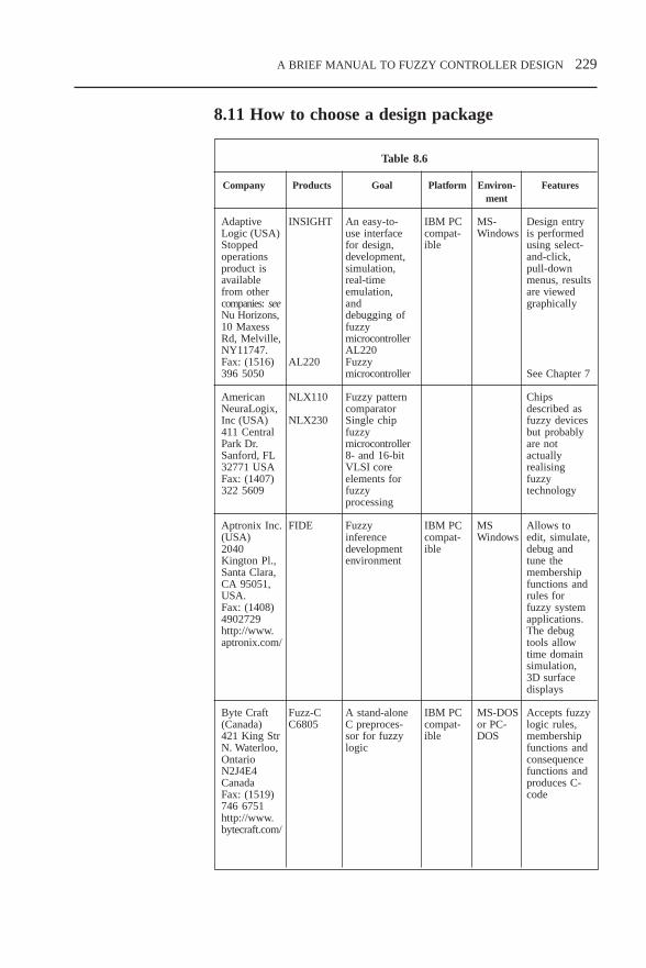
A BRIEF MANUAL TO FUZZY CONTROLLER DESIGN 229
8.11 How to choose a design package
Table 8.6
Company Products Goal Platform Environ- Featuresment
AdaptiveLogic (USA)Stoppedoperationsproduct isavailablefrom othercompanies: seeNu Horizons,10 MaxessRd, Melville,NY11747.Fax: (1516)396 5050
AmericanNeuraLogix,Inc (USA)411 CentralPark Dr.Sanford, FL32771 USAFax: (1407)322 5609
Aptronix Inc.(USA)2040Kington Pl.,Santa Clara,CA 95051,USA.Fax: (1408)4902729http://www.aptronix.com/
Byte Craft(Canada)421 King StrN. Waterloo,OntarioN2J4E4CanadaFax: (1519)746 6751http://www.bytecraft.com/
INSIGHT
AL220
NLX110
NLX230
FIDE
Fuzz-CC6805
An easy-to-use interfacefor design,development,simulation,real-timeemulation,anddebugging offuzzymicrocontrollerAL220Fuzzymicrocontroller
Fuzzy patterncomparatorSingle chipfuzzymicrocontroller8- and 16-bitVLSI coreelements forfuzzyprocessing
Fuzzyinferencedevelopmentenvironment
A stand-aloneC preproces-sor for fuzzylogic
IBM PCcompat-ible
IBM PCcompat-ible
IBM PCcompat-ible
MS-Windows
MSWindows
MS-DOSor PC-DOS
Design entryis performedusing select-and-click,pull-downmenus, resultsare viewedgraphically
See Chapter 7
Chipsdescribed asfuzzy devicesbut probablyare notactuallyrealisingfuzzytechnology
Allows toedit, simulate,debug andtune themembershipfunctions andrules forfuzzy systemapplications.The debugtools allowtime domainsimulation,3D surfacedisplays
Accepts fuzzylogic rules,membershipfunctions andconsequencefunctions andproduces C-code
CH8.PM5 6/12/97, 2:01 PM229

230 A BRIEF MANUAL TO FUZZY CONTROLLER DESIGN
Table 8.6 continued
Company Products Goal Platform Environ- Featuresment
BellHelicopterTextron (USA)TSIE, Inc.P.O. Box14155AlbuquerqueNM 87191USAhttp://www.bellhelicopter.textron.com/home.html
CICSAutomation(Australia)P.O. Box 570Wallsend,NSW 2287,AustraliaFax: (612)7965 6705http://www.cicsanto.com.au
FlexibleIntelligenceGroup, LLC(USA)P.O. Box1477TuscaloosaAL 35486USAhttp://www.flextool.com/ftfs.html
FRILSystems Ltd(UK)BristolBusinessCentre,MaggsHouse, 78Queens Rd.Bristol BS81QX UK
FULDEK
UNAC
FlexToolA modularsoftwaretool whichprovides anenviron-ment forapplyingfuzzysystems todiversedomains.
FRIL
Fuzzy logicdevelopmentkit – a CADpackagewritten invisual BASIC
Prototypingand imple-mentingadvancedprocess controlalgorithms,diagnosticstudies andsignal analysis
A VersionM2.2 is aMATLABversion whichprovides anenvironmentfor design inMATLAB
Logic-programminglanguage forsolvinguncertaintyproblems
IBM PCcompat-ible
Includesasoftwarepackageand ahardwarecontrol-ler
Various
Various
MS-DOSor PC-DOS
MATLABenviron-ment
Allows theuser to executethe resultingfuzzyinferences.Many options ofdefuzzificationand encodingare providedso that theuser can findthe best fit foran application
Fuzzy controltoolbox providesa graphic userinterface,simulation andtesting of thefuzzy controlsystems. Whencompleted, thedesign isimplementeddirectly on theprocess
Combines theuncertaintyhandlingcapabilities,qualitativereasoningcapabilities offuzzy systemswith theevolutionarylearningcapabilities ofgeneticalgorithms
Includes anopportunity tomanipulatefuzzy andprobabilisticuncertainties,enablingdifferent formsof uncertaintyto be integratedwithin a singleframework
CH8.PM5 6/12/97, 2:01 PM230

A BRIEF MANUAL TO FUZZY CONTROLLER DESIGN 231
Table 8.6 continued
Company Products Goal Platform Environ- Featuresment
FuzzySystemsEngineering(USA)12223Wilsey Way,Poway CA92064 USAFax: (1619)748 7384
FUZZYSOFTAG andGTSTrautzelGmbH(Germany)Gottlieb-Daimler-Str.9 D-24568Kaltenkirchen,GermanyFax: (49)4191 88665
FuzzyWare(USA)P.O. Box11287KnoxvilleTn 37939USAFax: (1-615)588 9487
HIWARE(Switzer-land)Tel: (41-61)331 7151
HyperLogicCorp. (USA)P.O. Box300010Escondido,CA 92030USAFax:(1619)746 4089
FuzzyKnowl-edgeBuilder,FuzzyDecisionMaker, andFuzzyThoughtAmplifier
FS-FUZZY-SOFT
FuziCalc
HI-FLAG
CubiCalc,CubiCalcRTC,CubiCalcRuleMaker,CubiCard,andCubiQuick
Support andassistance indesign fuzzysystems,modelling realsystems,generating andtuning fuzzyrules
A completefuzzy logicbasedoperatingsystem whichassists indevelopingcomplexsoftware
A spreadsheetwhich dealswith fuzzyuncertainnumbers whileretaining aconventionalspreadsheetuse
Fuzzydevelopmentenvironment
Generating,writing, andverifying fuzzyrules
IBM PCcompat-ible
IBM PCcompat-ible
IBM PCcompat-ible
IBM PCcompat-ible
IBM PCcompat-ible
MS-Windows
MS-Windowsand MSC/C++orBorlandC/C++
MS-Windows
MS-Windows
MS-Windows
Helps inmaking thedecisions,provides aninterface forcapturingexpert’sjudgements
Includes:graphicsimulationwithout theneed forcompilation,systemintegration,structural andmodularediting,efficient C-codegeneration
Allows to putin any cell aprecisenumber, afuzzy number,or a range ofvalues.Includesfinancial andmathematicalfunctions
Supports mostof theMOTOROLA’smicrocontrollers
Provides cost-effectiveprogrammingsupport forpopular C andC++ compilers
CH8.PM5 6/12/97, 2:01 PM231

232 A BRIEF MANUAL TO FUZZY CONTROLLER DESIGN
Table 8.6 continued
Company Products Goal Platform Environ- Featuresment
GrymerWormTongue Inc.(UK)199 AskewRd. LondonUKhttp://www.compu-link.co.uk/~the-zone/assist.html
ICCTTechnologies(Canada)Suite205,500Alden Rd.Markham,Ontario L3R5H5 CanadaFax: (905)475 5350http://www.stria.ca/icct
IndigoSoftware(UK)25 ClarenceSq.ChelthenhamGloucester-shire GL5O4JP UKFax: (44-01242)243225http://www.indigo.co.uk
Inform(Germany)Pascalstrasse23 D-5100AachenGermanyFax:(492408) 6090http://www.fuzzytech.com
AssistVisualDesigner
FuzzyC++
FuzzyShell
FuzzyExpert–a C++sourcecodelibrary forembeddedfuzzyapplica-tions
fuzzyTECH
Fuzzyknowledgebased systemgenerator
A softwarepackageincluding afuzzylanguage,compilerA softwaredesign anddevelopmentpakage
Includes allcode one needsto delay fuzzyreasoning inone’sapplication
Developmentand designtools for fuzzysystem design
IBM PCcompat-ible
IBM PCcompat-ible
Variousplat-forms
Various
MS-Win-dows
MS-Win-dows
C++
GUI design,codegeneration forC/C++ andHex,self-organisation offuzzy rulesand sets,adaptive fuzzycomputationalalgorithms,support forfuzzy FPGA/ASIC chips
Features thelibrary of C++codes to createapplicationswith fuzzylogic. Includesultra-fast fuzzyexpert system
Provides alltools for fuzzysystem design:onlinetechnology formodificationsof the runningsystem,all-graphicaland othereditors,multiplegraphicalanalyser and
CH8.PM5 6/12/97, 2:01 PM232

A BRIEF MANUAL TO FUZZY CONTROLLER DESIGN 233
tracers,NeuroFuzzyandDataAnalysermodules, etc.
Easy-to-develop onlineapplications,possibility ofproducingembeddedapplicationswith the C-codegeneration,rapidprototyping ofthe controlsystems
Threepowerfulgraphicaltools: fuzzyrule editor,fuzzymembershipprocessor andfuzzygraphicalanalyser;fuzzy rulesand member-ship functionscan bemodifiedinteractively inreal-timeimplementa-tion to tune asystemresponse
Table 8.6 continued
Company Products Goal Platform Environ- Featuresment
IntegratedSystems(USA)3260 Jay Str.Santa Clara,CA 95054http://www.isi.com
KentRidgeInstruments(Singapore)Blk 51 AyerRajah IndEstAyer RajahCres.Singapore0513Fax:(65)7744695
RT/FuzzyinMATRIXx
FlexControl
Practical toolfor fuzzysystemsmodelling andsimulation inan integratedenvironment
Rapidprototypingsoftware forfuzzy controlsystems
MS-Win-dows
UNIXwork-stations
IBM PCcompat-ible
CH8.PM5 6/12/97, 2:01 PM233

234 A BRIEF MANUAL TO FUZZY CONTROLLER DESIGN
Table 8.6 continued
Company Products Goal Platform Environ- Featuresment
LogicProgram-mingAssociatesLtd. (UK)St.4, RVPB,Trinity Rd,LondonSW18 3SX,UKFax: (44181) 8740449http://www.lpa.co.uk
ManagementIntelligenterTechnologien(MIT)GmbH(Germany)Promenade 952076AachenGermanyFax: (492408) 94582
The MathWorks(USA)24 PrimePark WayNatick, MA01760 USAFax: (1508)653-6284http://www.mathworks.com/iee
FLINT
DataEngine
PENSUM
FuzzyLogic ToolBox forMatLab
Fuzzy logicinferencingsystem thatmakes fuzzytechnology(fuzzyvariables,modifiers,rules,defuzzification)within asophisticatedprogrammingenvironment(PROLOG)
Fuzzy andneuro dataanalysis andprocess controlModellingcomplexcontrolsystems usingfuzzy Petrinets
A powerfultool for fuzzysystem design,analysis, andsimulation inan integratedenvironment
IBMcompat-ible PCorUNIXstations
IBMcompat-ible PCorSUN-SparcstationsUNIX-station
Various
Applied toprogram fuzzyexpert systemsAllows theinclusion offuzzy rules,modifiers,variables anddefuzzifiersinto an expertsystem
Familyincludes:• DataEngine
– develop-ment tool fordata analysis
• DataEngineADL –library for theintegrationof dataanalysissolutionsinto existingsoftware
• DataEngineV.i. – virtualinstrumentforLabVIEW,has theadvantage ofmorehuman-likecontrol
Allowscreation andediting offuzzy inferencesystems eitherby hand, withinteractivegraphical toolsor command-line functions,or bygeneratingautomaticallywith clusteringor adaptiveneuro-fuzzytechniques
MS-Win-dows,Mac orDOS +PROLOG
MS-Windows
Various
CH8.PM5 6/12/97, 2:01 PM234

A BRIEF MANUAL TO FUZZY CONTROLLER DESIGN 235
Table 8.6 continued
Company Products Goal Platform Environ- Featuresment
MentaLogicSystems(Canada)145 RenfrewDr.Markham,Ontario L3R9R6 CanadaFax: (1-905)940 0321
MetusSystemsGroup(USA)1 GriggsLaneChappaquaNY 10512USA
MODiCO,Inc. (USA)P.O. Box8485KnoxvilleTN 37996-0002 USAFax;(1-423)584 4934http://www.modico.com
Quick-Fuzz,Auto-Fuzz,Multi-Fuzz,Flex-Fuzz,Process-Fuzz, AutoSim-Fuzz,Fuzz-Drive, F-MTOS,CT-FLC
Metuslibrary
FUZZLE –fuzzysystemsdevelop-ment shellwhichgeneratesprogramsin differentlanguagesand has itsownexecutionmodule
A largenumber ofdifferentproductsaiming at:fuzzycontrollerdesign,applicationsdevelopment,fuzzyknowledgegenerating,simulating, andimplementing
A library offuzzyprocessingmodules for C/C++
Softwareallowing theprogrammingof an inferenceengine,execution,output in C orFORTRANcode, editingand analysis.Able to createrules from data
IBM PCcompat-ible
MS- orNT-Win-dows
Variouslan-guages
Specialises inthe develop-ment ofadvancedfuzzy logictechnologies
Module thatexecutesinferenceengines in agraphicalenvironmentwithoutcompiling orlinking sourcecodeMixed inputprocessingcapability thatallowsnumericalinput dataentry as wellas linguisticAnalyseperformance ofthe rules
CH8.PM5 6/12/97, 2:01 PM235

236 A BRIEF MANUAL TO FUZZY CONTROLLER DESIGN
Table 8.6 continued
Company Products Goal Platform Environ- Featuresment
MotorolaInc.Apply to thenearestdealer
NationalSemicon-ductor(USA)2900 Semi-conductor Dr.PO Box58090 SantaClara, CA95052 USAhttp://www.nsc.com
OmronCorp.(Japan)4-7-35Kitashinagawa,Shinagawa-ku, Tokyo140 JapanFax: 03-5488-3273http://202.32.89.iy
ParallelPerformanceGroup(USA)Fax: (1-520)774-0896http:/www.ppgsoft.com/ppgsoft/oifin.html
FuzzyLogiceduca-tional kit
NeuFuz4
FuzzyInferenceSoftwareFS-30AT,FP-1000,FP-3000,FP-5000,E5AF
O’INKA
IBM PCcompat-ible
IBM PCcompat-ible, FP-3000,FB-30AT
Variousplat-forms
MS-Win-dows
MS-DOS
A new versionincludesFUDGE whichgeneratesassembler orANSI C codefor Motorola’smicrocontrollers
Includeslearning kitsand develop-ment systemsand softwarepackages fordesign anddevelopingneuro-fuzzysystems, fuzzyrules andmembershipfunctions
Definable rulesand member-ship functions,simulations,trainingexercisesFuzzymicrocontrollersand chips,temperatureprocesscontroller
Allows forintegration offuzzy logic,neuralnetworks anduser-definedmodules in asingleframework.Combinesgraphic userinterface,designvalidation,simulation anddebugging, C-codegeneration anddesigndocumentation
The computer-based tutorialset includes:fuzzy logic andcontrolfundamentals,fuzzy systemdesign andimplementation
Neural-fuzzytechnology forcontrolapplicationswhich usesbackpropagationto select fuzzyrules andmemberships
Comprehensivefuzzy inferencetools
Designframework forbuildingintelligentsystems
CH8.PM5 6/12/97, 2:01 PM236

A BRIEF MANUAL TO FUZZY CONTROLLER DESIGN 237
Table 8.6 continued
Company Products Goal Platform Environ- Featuresment
SGS-ThomsonMicroelec-tronicshttp://www.st.comcontact adealer
Siemens AG(Germany)Attn: W.KeimSiemens AGANL 441-VEG.ScharowskyStr. 2 91052ErlangenGermanyFax: (499131)732127E-mail:[email protected]
Syndesis Ltd(Greece)Iofondos 7Athens GR-116 34,GreeceFax: (30-1)7257829E-mail:[email protected]
WARPprocessorandsoftwaredevelop-ment tools
SieFuzzy
FLDE – anapplicationgeneratorwhichallows adesigner todevelopand testembeddedfuzzyapplica-tions
Developmentsoftware toolsfor WARPfuzzyprocessor
Softwaredevelopmenttool fordesigning,simulation,testing fuzzysystems,compiling anyresulting C-code
Fuzzy logicdesign toolproducing anANSI C-codefor embeddedapplications
IBM PCcompat-ible
Variousplat-forms
IBM PCcompat-ible
Includeseditor,compiler,debugger,simulator andexporter fordesigningfuzzycontroller,generatingcode andtestingapplications
Interfacingwith standardsoftwarepackages(Matlab andMathematica),automaticoptimisationof fuzzysystems,user exten-sions (forversion 2.0)
Ability for auser to achievean optimalcodegeneration interms ofmemory andprecision bychoosing froma wide rangeof C datatypes. The C-code generatedis self-contained
MS-Win-dows
MS-Win-dows
CH8.PM5 6/12/97, 2:01 PM237

238 A BRIEF MANUAL TO FUZZY CONTROLLER DESIGN
Table 8.6 continued
Company Products Goal Platform Environ- Featuresment
TecQuipmentLtd (UK)Bonsall Str.Long Eaton,NottinghamNG10 2ANEnglandFax: 44(0)1159731520E-mail:[email protected]
TogaiInfraLogic(USA)18TechnologyDr. Suite146 IrvineCA 92718USAFax: (1714)588 3808
WolframResearchInc. (USA)100 TradeCenter Dr.ChampaignIL 61820-723 USATel: 1-217-398-0700Fax: 1-217-398-0747
CE124FuzzyLogicSystem – acombinedhardwareandsoftwaretool forlearningabout andimple-mentingfuzzysystems
TILShell+and otherproducts
FuzzyLogic Pack
Self-containedteaching aidfor students toexplain fuzzylogic usinganalogue fuzzysystemelementscomplementedby fuzzysoftware
Softwaredevelopmenttool whichprovides a wayto describefuzzy systems,test themthroughsimulation andcompile animplementationcode
Creating,modifying, andvisualisingfuzzy sets andsystems
IBM PCcompat-ible
Various
Availablefor allplat-formsthat runMathe-matica2.2
Various
Mathe-matica2.2 orlater
Includessoftwarepackageenabling fuzzycontrol to beimplementedon an IBMcompatible PC.The opendesign allows awide range offuzzy logic andcontrolexperiments tobe developedand extended tosuit the user’sneeds
Includes fuzzyprogramminglanguage,object editorsand compilers
CH8.PM5 6/12/97, 2:01 PM238

PROBLEMS AND ASSIGNMENT TOPICS 239
9 PROBLEMS ANDASSIGNMENT TOPICS
Chapter 1Choose any one of the following topics and write a short (10–15pages) essay.
1. What I like in fuzzy logic is ...2. What I do not like in fuzzy logic is ...3. Fuzzy sets theory was introduced by Lotfi Zadeh in 1965.
Why not earlier or later?4. Probability vs fuzziness: Which is the winner?5. In 1975, William Kahan pointed out some contentions to
fuzzy logic:
I cannot think of any problem that could not be solvedbetter by ordinary logic.
What Zadeh (and fuzzy logic) is saying is the same sortof thing as: ‘Technology got us into this mess and nowit cannot get us out.’
What we need is more logical thinking not less. Thedanger of fuzzy theory is that it will encourage the sortof imprecise thinking that has brought us so much trouble.
Choose any of these statements and try to prove or refute it.
6. What is wrong in fuzzy sets theory?7. Present your understanding of the concepts of complexity,
uncertainty, ambiguity, imprecision, vagueness. Where is theplace for fuzziness among these concepts?
8. Fuzzy theory is often determined as an instrument to modeluncertainties. Do you agree with this statement? Why?
9. Historically, a long time before fuzzy theory was putforward by L. Zadeh, a probability theory had beenconsidered as a primary tool for representing uncertainties,which is why some researchers look at fuzzy theory as arival to probability. What is your position in this argument?
10. Propose a new device or a method where fuzzy technologycould be implemented.
CH9.PM5 6/12/97, 3:06 PM239

240 PROBLEMS AND ASSIGNMENT TOPICS
11. Propose a plan and ideas for a fuzzy systems laboratory.12. A fuzzy logic educational kit: ideas, proposals, realisation.13. Fuzzy control and classical control: what is the advantage
of fuzzy control?14. What I do not understand in fuzzy logic is ...15. What do you consider as the most important part of fuzzy
theory and technology?16. Describe a possible application of fuzzy technology in car
design.17. Propose some ideas for an automatic car driver
implementation based on fuzzy technology.18. Propose a brief plan of an intelligent superhighway imple-
mentation based on fuzzy technology.
Chapter 21. Give some examples of crisp sets.2. In the examples given in problem 1, is it easy to determine
for any element of the universal set whether it belongs toa particular set or not?
3. For the sets A and B, pictured in Fig. 2.3, determine
A B A B A B, , ,∩ ∪4. Determine the complement:
to the set of all odd numbers; to the set of all numbers which are multipliers by 5.
5. Determine the intersections of:
the multipliers by 4 and the multipliers by 3; the multipliers by 5 and the multipliers by 6; the multipliers by 2 and the multipliers by 8; the multipliers by 4 and the multipliers by 6.
6. Right or wrong?
the set of horses which won the races is a subset of allracing horses;
the set of white cats is a subset of all cats older than twoyears;
the set of all values for room temperature is a subset ofall possible values for room temperature.
7. What is the universal set for the subset of pens?8. What is more general, a crisp set or a fuzzy set? Can you
consider a crisp set as a special case of a fuzzy set or, vice
CH9.PM5 6/12/97, 3:06 PM240

PROBLEMS AND ASSIGNMENT TOPICS 241
versa, a fuzzy set as a special case of a crisp one?9. Right or wrong?
if the universal set has a finite number of elements, itscrisp subset has a finite number of the elements;
if the universal set has a finite number of elements, itsfuzzy subset has a finite number of the elements.
10. Right or wrong?
every fuzzy set can be considered as a subset of theuniversal set;
the universal set is another fuzzy set; a fuzzy set is completely determined by its membership
function; a fuzzy set is the union of all its level sets; a membership function is the union of all its membership
degrees; a fuzzy set is a crisp set of pairs (u, µ(u)), where u ∈ U
is an element of the universe and µ(u) is its membershipdegree.
11. Determine the intersection and the union of the sets of:
all men taller than1.8 m and all men shorter than 1.9 m; all women older than 25 and all men younger than 18; of red pencils and blue pencils; of green pencils and all pencils longer than10 cm.
12. Draw the membership functions for the fuzzy sets of:
high indoors temperatures; good indoors temperatures.
13. Based on the results of Problem 12, construct themembership functions for:
not high indoors temperatures; good or high indoors temperatures; 0.5-level set of the fuzzy set of high indoors
temperatures.
14. Right or wrong?
the height of a fuzzy set is determined by the elementon its crossover level;
0.2-level set has more elements than 0.5-level set.
15. Draw the membership functions for the fuzzy sets of:
CH9.PM5 6/12/97, 3:06 PM241

242 PROBLEMS AND ASSIGNMENT TOPICS
low atmospheric pressure; high blood pressure.
16. Based on the results of Problem 15, construct themembership functions for:
not high blood pressure, low atmospheric pressure and high blood pressure.
17. Propose membership functions to determine fuzzy sets ofultrasonic sounds and infrasonic sounds. What universe canbe used to determine these fuzzy sets?
18. Depending on age, a person can be called a baby, a child,a teenager, an adult. Determine membership functions todescribe these fuzzy sets.
19. After a traffic accident, the witnesses have described thespeed of one vehicle involved as ‘very high’ and of anotherone as ‘rather high’. Propose the membership functions todetermine these fuzzy sets.
20. In the graphic presentation of the membership functionsdescribing fuzzy sets of ‘well educated people’ and ‘pooreducated people’, which unit would you propose to scalethe universe?
21. α-cut can be considered as an example of a way to converta fuzzy set into a crisp one. What is this conversionnecessary for?
22. Right or wrong?
operations on fuzzy sets can be determined in any wayone wants;
operations on fuzzy sets have one strict definition; both the union and the intersection operations can be
determined through the triangular norm; the triangular norm is a two-place function.
23. Based on Definition 2.8, propose a new function to realiset norm.
24. Propose another problem similar to the one considered inSection 2.2 (see Fig. 2.11) to illustrate a possibility of usingdifferent ways to calculate the t norm.
25. Consider two fuzzy sets:
long pencils = pencil1/0.1, pencil2/0.2, pencil3/0.4,pencil4/0.6, pencil5/0.8, pencil6/1,
medium pencils = pencil1/1, pencil2/0.6, pencil3/0.4,pencil4/0.3, pencil5/0.1.
CH9.PM5 6/12/97, 3:06 PM242

PROBLEMS AND ASSIGNMENT TOPICS 243
Use two methods to calculate t norms. Determine the resultsof the union and the intersection of these fuzzy sets.Compare these results.
26. Apply two fuzzy sets with the membership functions givenin Fig. 2.4b. Use two methods to calculate t norms.Determine the results of the union and the intersection ofthese fuzzy sets. Compare these results. What can you sayabout the dependence of the result membership functionshapes on the t norm calculation method used?
27. Which ones of the following functions could berecommended as the membership functions for the fuzzysets ‘about 5’, ‘much higher than 10’, ‘low’:
28 Let the fuzzy sets A, B and C be the subsets of the universe1,2,3, . . . , 199, 200.
Let A = 1/0.1,2/0.3,3/0.3,4/0.4,5/0.5,6/0.7,7/0.8,8/0.9,9/1,10/1 andB = 1/0.1,2/0.3,3/0.5,4/0.7,5/0.9,6/1,7/0.8,8/0.5,9/0.2,10/0. Find out the fuzzy sets
C = A + B;C = A * B;C = (A + B)*A;C = A*(A + B).
29. Under the conditions of problem 28, find the fuzzy sets
C = A2;C = 1/B.
30. Calculate the results of the following operations with theintervals:
[1,2] + [2,4] [–3,4] – [5,6] [–3,4] × [–2,3] [7,8] / [2,4] [7,8] / [–4,–2]
31. Which of the functions below could be consideredreasonable to serve as a membership function for the fuzzyset ‘medium’ in control applications?
CH9.PM5 6/12/97, 3:06 PM243

244 PROBLEMS AND ASSIGNMENT TOPICS
32. Actual resistance values of any real resistors are known tobe different from nominal ones. Can this actual value beconsidered as a fuzzy set?
33. Propose membership functions to describe ‘a fuzzy resistor’with a nominal value of 1 MΩ and another one of 5.6 kΩ.
34. Determine a fuzzy equivalent resistance for the circuit givenbelow where R1 and R2 are fuzzy resistors described inProblem 33.
Chapter 31. What is the difference between Mamdani-type fuzzy
controller and Sugeno-type fuzzy controller?2. Which method of reasoning is the most appropriate model
of human thinking?
Boolean logic; fuzzy logic; semantic networks.
3. Right or wrong?
fuzzy controller operation is based on rules processing; fuzzy rules processing results in a crisp output, which is
applied to an object or process under control; a rules table uses measured physical variables as its
inputs; fuzzy processing consists of choosing one of the rules
and calculating the output corresponding to this rule.
4. Describe fuzzy processing and calculate its output forExample 3.1 considered in Section 3.2.3 with the pressureerror of –7 kPa and temperature 12°.
5. Suppose the fuzzy rule has two conditions in its antecedent part.Two real inputs match the membership functions correspondingto these conditions with the degrees of 0.3 and 0.7. Calculatethe applicability degree of these inputs to this rule.
6. Let the fuzzy controller have three rules. Each rule has twoconditions in the antecedent parts and two inputs. Two realinputs match the membership functions corresponding to theconditions of the first rule with the degrees of 0.3 and 0.7,of the second one, 0 and 0.9, and of the third one, 0.4 and0.5. The antecedent parts of the rules are:
R1
R2
CH9.PM5 6/12/97, 3:06 PM244

PROBLEMS AND ASSIGNMENT TOPICS 245
y = 0.4x1 + 0.8 x
2;
y = 0.1x1 + 0.9 x
2;
y = 0.2x1 + 0.5 x
2;
where y is the controller output. Calculate the controller outputcorresponding to these inputs.7. What stages can fuzzy controller operation be divided into?8. What does a knowledge base of a fuzzy controller contain?9. What scales can be proposed for vacuum cleaner fuzzy
controller inputs? What scale can be used to describe asurface type? What scale can be used for the output if apossible sucking force range is up to 100 N?
10. What are the typical inputs and outputs:
for a PD-like fuzzy controller? for a PI-like fuzzy controller? for a PID-like fuzzy controller?
11. Table 9.1 contains rules for a PD-like fuzzy controller. Fillin empty places.
Table 9.1
NB NM NS Z PS PM PB
NB NB NS Z
NM NM
NS NS Z
Z Z
PS Z PS
PM Z PM
PB Z PS PB
12. Suppose Table 9.2 contains rules for a PI-like fuzzycontroller. Fill in empty places.
Table 9.2
NB NM NS Z PS PM PB
NB PB PB PS Z
NM PM
NS PS Z NS
Z Z
PS Z
PM NM
PB Z NS NB
∆∆∆∆∆ee
∆∆∆∆∆ee
CH9.PM5 6/12/97, 3:06 PM245

246 PROBLEMS AND ASSIGNMENT TOPICS
13. Right or wrong?The structural difference between PD-like fuzzy controllersand PI-like fuzzy controllers is concentrated mainly in:
choice of inputs; choice of outputs; choice of rules.
14. If all the rules are to be formulated by experts, what typeof fuzzy processing can be recommended?
15. What functions are usually applied in the consequent partof the rules in Sugeno fuzzy processing?
16. What type of fuzzy processing should be chosen for thefuzzy controller designed for a robot mobile application?
17. Which defuzzification method can be recommended for theSugeno-type fuzzy controller with two inputs and 25 rulesdesigned for a process control system?
18. Give the definition of controller stability. How does a stablecontroller differ from an unstable one?
19. What is the advantage of a hierarchical fuzzy controller overa simple one?
20. Determine which ones of the rules given below represent afuzzy rules base.
If temperature is below 15o then switch on a heater for5 minutes.
If temperature is low then switch on a heater for 5minutes.
If temperature is below 15o then switch on a heater fora few minutes
If temperature is low then switch on a heater for a fewminutes
where Low means below 16° and a few means between 3 and5.
21. In a multilevel hierarchical structure, which level worksunder more uncertain conditions, high or low?
22. Do you agree with the statement that a fuzzy controller isan applied fuzzy expert system?
23. Formulate some rules for the fuzzy controller controlling themovement of a car approaching a stop sign. What inputsshould this controller have?
24. What type does the controller designed in Problem 23 have?
CH9.PM5 6/12/97, 3:06 PM246

PROBLEMS AND ASSIGNMENT TOPICS 247
Chapter 4Fuzzy control has the potential to change the way people andgoods are moved around a factory, a neighbourhood, city, country.Steering a moving vehicle, controlling the speed at which avehicle travels, avoiding obstacles and target tracking are keyaspects where fuzzy logic could be implemented to reduce thework on humans. By removing the need for humans to worryabout breaking the speed limit, they can concentrate more onwhere they are going and what is in their way, and hopefully thatwill reduce the number of deaths and accidents on the roads eachyear. This set of problems tends to help in developing fuzzycontrollers for an intelligent super highway.
1. We know that when a set of traffic lights is green, the car cantravel through the intersection, if the light is yellow, then thedriver must either stop or hurry through the intersection.Write down the corresponding rules set for a fuzzy controller.
2. Take into account the time, how long the current light hasbeen fired. How should the previous set be modified?
3. Now try to design a fuzzy controller for traffic lights. Whichinputs should be used for this controller?
4. Now design a fuzzy controller to stop a car at the trafficlights. Which inputs should you use? How should youformulate the rules?
5. Parking is some drivers’ worst nightmare. Write down therules for a fuzzy controller performing reverse parking.
6. On the future intelligent superhighway, all cars will beseparated into different palettes, which are groups of carstravelling with the same speed. The distance betweenpalettes as well as the distance between cars within a paletteshould be kept constant during travelling. Determine themain difference between two fuzzy controllers: the first onecontrolling the distance between the palettes and the secondone controlling the distance between cars within a palette.
7. What sensors will be required to realise the fuzzy controllersmentioned above?
8. Propose a rules table for a PI-like fuzzy controller for aroom temperature control.
9. Take a manual for any control device. Design a rules tablebased on this manual.
10. The fuzzy control system developed for an automatic flightcontrol of the X-29 aircraft consists of three PID-like fuzzycontrollers: for pitch, roll and yaw control [Luo95]. Whatis the main difference between these controllers?
CH9.PM5 6/12/97, 3:06 PM247

248 PROBLEMS AND ASSIGNMENT TOPICS
11. In each fuzzy controller described in Problem 10, the rulesset consists of coarse and fine rules. The coarse rules aredesigned to supply fast response with a large control input,while the fine rules are designed to make a fine adjustmentto improve a dynamic stability. Is it a hierarchical structure?If so, what is a lower level?
12. Table 9.3 contains the protocol results for some computercommunication sessions. The fuzzy system to be designedhas to evaluate the communication quality. It may consistof rules like:
If errors are seldom and repeats are seldom then quality ishigh.
Which inputs and outputs would you like to apply to thisfuzzy system?
Table 9.3
Session A B C D E F
Packets sent 551 52 37 187 50 1185
Packets 1861 1234 97 34 129 4717received
CRC errors 0 0 2 1 0 1
Retransmits 153 48 232 194 232 141
Timeouts 50 98 68 435 68 42
Failed sanity 1 0 0 0 0 0checks
Incomplete 1 1 1 2 1 1packets
Bytes 608 305 894 567 640 195 427 456 648 979 1584 727received
Bytes 0 0 0 0 0 0discarded
13. Can a number of retransmits in Problem 12 be applied asan input?
14. Add some other rules to the fuzzy system of Problem 12.15. A control engineer often evaluates a controller quality by
analysing its response. What inputs for this fuzzy evaluationsystem could you propose?
CH9.PM5 6/12/97, 3:07 PM248

PROBLEMS AND ASSIGNMENT TOPICS 249
16. Develop some rules for the fuzzy evaluation system ofProblem 15.
17. Which membership functions, Fig. 9.1a, b, c or d would youprefer to apply to model a fuzzy controller error input andwhy?
18. The fuzzy controller has two inputs: error (e) and changeof error (∆e), and its membership functions are presentedin Fig. 4.25. This controller is given by the rules set of Table9.4. Is this rules set complete? Why?
Table 9.4
NB NS Z PS PB
NB PB PB Z
NS PB PB Z
Z Z NB
PS PS NS NB
PB Z NS NB
Chapter 51. What are conventional and non-conventional methods for
fuzzy controller parameter adjustment?2. What is the main reason for an ANN application in a fuzzy
controller design?
NB NS Z PS PB
0-1-2
ErrorNB NS Z PS PB
0-1-2
Error
NB NS Z PS PB
0-1-2
Error
NB NS Z PS PB
0-1-2
Error
b)a)
c) d)Fig. 9.1. Membershipfunctions
∆ee
CH9.PM5 6/12/97, 3:07 PM249

250 PROBLEMS AND ASSIGNMENT TOPICS
3. What are the similarities and differences between neuralnetwork and genetic algorithms techniques?
4. What is the difference between genetic algorithms andevolutionary algorithms?
5. Which one of the methods, genetic or evolutionaryalgorithms, could be recommended for the following:
an initial formulation of the rules; an adjustment of the membership function widths; tuning of the fuzzy controller output scaling factors.
6. ANN operation depends on nonlinear activation functions.
Show that a step function is a special case of a sigmoidfunction.
Is a ramp function a special case of the sigmoidfunction?
How do you approximate a Gaussian function? Can it beconsidered as a combination of two sigmoid functions?If so, in which case?
7. According to [Kung93] the most popular neural model is atwo-layer back propagation network. Give two reasons why.
8. The response of a system controlled by a fuzzy controllerdemonstrates a large overshoot. Which of the fuzzycontroller scaling factors should be adjusted and how?
9. If the steady state error value is unacceptable, how wouldyou adjust the parameters of the fuzzy controller?
10. Will the adjustment recommended in Problem 9 changeother fuzzy controller characteristics?
11. In the process of choosing the scaling factors for the X29aircraft flight fuzzy controller [Luo95], the scaling factorsare first estimated by evaluating the largest possible valueof each variable and are then adjusted to give a betterperformance in terms of quick response and small trackingerrors. What do you think of this procedure? What does thestage of an initial choice include?
12. In an ANFIS system [Jang95], which part of the fuzzycontroller is realised by the ANN?
13. [Wu96] starts with the statement that ‘fuzzy control is adirect method for controlling a system without the need ofa mathematical model, in contrast to the classical controlwhich is an indirect method with a mathematical model.’ Doyou agree with this definition?
CH9.PM5 6/12/97, 3:07 PM250

PROBLEMS AND ASSIGNMENT TOPICS 251
Chapter 61. How would you propose to improve a fuzzy controller
design package which you applied?2. How many ‘bugs’ have you discovered working with the
design package?3. What are the main features of the fuzzy controller design
package?4. What was the main reason for including the neuro-fuzzy
module into a fuzzy design package?5. Why did large companies wish to produce their own fuzzy
design packages? What did these packages include?6. How is a typical fuzzy design package organised?7. What level of a human–machine interface is usually
achieved in a fuzzy design package? How can you proveyour conclusion?
8. What type of programming is required from a user of adesign package?
Chapter 71. In a hardware implementation,
when are analog circuits preferred over digital circuits? when are digital circuits preferred over analog circuits? when are hybrid circuits preferred over either analog or
digital circuits?
2. Can you propose a way to improve the performance of afuzzy processor?
3. Which stages of a fuzzy controller operation must beoptimised first of all? Why?
4. Can a fuzzy controller work in a real-time regime? Whatdoes it depend on?
5. What is a fuzzy coprocessor applied for?6. How is the joint operation of a general purpose digital
processor and a fuzzy coprocessor organised? Whichoperations should be performed by each processor?
7. Briefly describe the design of any fuzzy coprocessor chipavailable on the market. What are the performancecharacteristics of this chip?
8. What is a fuzzy processor development system for? How isit applied?
9. Which types of membership functions are usually appliedin fuzzy system hardware implementation? How do youexplain this choice?
CH9.PM5 6/12/97, 3:07 PM251

252 PROBLEMS AND ASSIGNMENT TOPICS
10. In Fig. 7.8, an electrical circuit diagram for Z-typemembership function realisation is given. What can bemodified in this circuit to make it realise the S-type?
11. Propose an electrical circuit to realise a P-type membershipfunction.
12. What precision can be achieved in an analogimplementation of fuzzy controllers?
CH9.PM5 6/12/97, 3:07 PM252

DESIGN PROJECTS 253
10 DESIGN PROJECTS
This chapter discusses some possible topics for student projects.Consider the following topics as examples only. The topicspresented here could be useful for specialists and students withvarious backgrounds: engineering (electrical, computer,mechanical, aerospace), information technology, computer andmathematical sciences.
Projects 1 and 2The problem description is given in Section 4.1. The plantsimulation model is given on Fig. 4.1. Change initial conditionsin blocks 7, 16 to zero. At the starting point, these initialconditions set the vessel heading directed straight to thedestination point.
1. Design a fuzzy controller to move the vessel along the straightline with as small a deviation as possible. Simulate its operationand the vessel movement with a design package. Observing avessel trajectory, evaluate the controller quality.Try two versions of the controller:
using a deviation from the straight line as an input; using the deviation angle from the target direction as the input.
Try two inputs PI-like and PD-like fuzzy controllers. Compare thetrajectories with the previously observed ones.
Suggest a possible further improvement of the controllerquality.
2. Design a fuzzy controller to make a vessel perform a U-turnand then move along a straight line. The required time forcompleting a turn should be as small as possible. To simulate thisvessel movement, change the initial condition in block 16 of theplant model (See Fig. 4.1) to 180.
CH10.PM5 6/18/97, 8:16 AM253

254 DESIGN PROJECTS
Project 3. Temperature-compensated VCOIn Section 3.6.4 (Example 3.7) a fuzzy controller design forpower system synchronisation and stabilisation was considered.A similar problem is typical for signal generators of all types,which must compensate for the frequency drifts caused bytemperature changes. Usually discrete solutions combined withvoltage controlled oscillators (VCOs) are used. VCOs providevariable frequency control by varying the excitation voltagelevel. However, a discrete circuitry with a temperature sensorinput is required to provide a DC voltage offset to compensatefor frequency drift. This circuitry, composed of a variety ofpotentiometers and variable capacitors, requires calibration, aprocess in which just one system can often take hours tocalibrate.
The AL220 PAICTM (Programmable Analog IC, manufacturedby Adaptive Logic) can replace discrete compensation circuitryused with VCOs. The circuit diagram designed is given in Fig.10.1. In the temperature compensation application, the AL220operates as a look-up table. Voltage regions are defined for thetemperature sensor input and are used to control the voltageoffset level output. The voltage regions are variable and canchange in size from region to region and from system to system.Each voltage region maps to a specific voltage offset value foreach output through the rule set. The offset values are based onthe temperature characteristics of the circuitry beingcompensated.
The example algorithm developed by Adaptive Logic is in Fig. 10.2.
Fig. 10.1 Temperature-compensated VCO.Example circuitschematic developed byAdaptive Logic, Inc.
CH10.PM5 6/18/97, 8:16 AM254

DESIGN PROJECTS 255
The controller has just one input and one output.
Inputs: TEMPOutputs: VCO
Inputs regions:TEMP is –30...–25TEMP is –25...–20TEMP is –20...–15TEMP is –15...5TEMP is 5...20TEMP is 20...30TEMP is 30...35TEMP is 35...45TEMP is 45...60TEMP is 60...70TEMP is < 62TEMP is < 63.5TEMP is 64...66TEMP is > 66.5
The following rules have been proposed.Rules:
If TEMP is –30...–25 then VCO = 137.If TEMP is –25...–20 then VCO = 133.If TEMP is –20...–15 then VCO = 130.If TEMP is –15...5 then VCO = 128.If TEMP is 5...20 then VCO = 127.If TEMP is 20...30 then VCO = 129.If TEMP is 30...35 then VCO = 132.If TEMP is 35...45 then VCO = 130.If TEMP is 45...60 then VCO = 136.If TEMP is 60...70 and TEMP is < 62 then VCO = 141.If TEMP is 60...70 and TEMP is < 63.5 then VCO = 147.If TEMP is 60...70 and TEMP is > 68.5 then VCO = 174.If TEMP is 60...70 and TEMP is > 66.5 then VCO = 161.If TEMP is 60...70 and TEMP is 64...66 then VCO = 153.
The proposed temperature compensation algorithm is an openloop control. It operates as a look-up table. One rule adjusts theoutput voltage for each voltage region defined from thetemperature sensor input. Voltage region selection is based onthe temperature characteristics of the VCO and the frequencydeviation limits.
Fig. 10.2 An algorithmfor temperature driftcompensation
CH10.PM5 6/18/97, 8:16 AM255

256 DESIGN PROJECTS
Determine if the proposed controller is a fuzzy controller?What should one do to redesign it as a fuzzy controller? Makenecessary changes to get a fuzzy controller. Could the same circuitbe used to realise this controller?
Project 4. Sewer level controlIn 1992, a sewer in the main street of the Melbourne suburb ofKensington (Australia) collapsed leaving a large hole in themiddle of the road. For a few weeks, untreated sewage went intothe bay causing much public concern. The old sewer was madeof bricks. Over time, as the sewer level went up and down, themortar between bricks was loosened, which caused the collapse.To prevent further damage to the sewer, it was important to keepthe level in the sewer constant.
Four 45 kW pumps and piping were installed to bypass thecollapsed part of the sewer. Two of the pumps were driven by avariable speed drive (VSD) while the other two were fixed speed.Initially operators adjusted the frequency of the VSD to try to keepthe sewer level constant. However, due to the fluctuating flow ofsewage into the sewer, this was unsatisfactory. The humanoperators did not have a quick enough response.
The Hartmann & Braun PID controller was applied then. A4–20 mA level signal was looped into the controller. A level set-point was entered into the controller by an operator. The controlleracted to increase the frequency of the VSD if the level went abovethe set-point and to decrease the frequency of the VSD if the levelfell below it. During commissioning, the self-tuning function wastried, but it did not work properly. At first just proportional controlwas applied. The proportional gain was adjusted until the responsewas more or less satisfactory. Integral control was then added todecrease the steady-state error. Derivative control was tried but thismade the response worse.
Design a fuzzy controller to control the VSD. Determine thestructure of the controller, its inputs and the rules table. Whattype of a fuzzy controller should be chosen?
Project 5. A pumping station controlFresh water must be pumped from a reservoir to an elevated tankseveral kilometres away. Three pumps are to be installed andcontrolled by a fuzzy controller. The control strategy includesthe rule that if the water level in the elevated tank drops below7.9 m, a pump would start. If the level drops below 7.5 m, asecond pump would start and if the level dropped below 7.0 m,
CH10.PM5 6/18/97, 8:16 AM256

DESIGN PROJECTS 257
a third pump would start. Once the level reaches 8.7 m, a pumpwould stop. At 9.0 m, a second pump would stop, and at 9.2 m,all pumps would stop.
As the water pressure varies over a large range, it is necessaryfor each pump to have a variable speed drive to achieve thedesired flow rate. The water pressure varies due to changes in:
reservoir water level; elevated tank water level; consumer demand for water in the region.
The last influence can be modelled as a random variabledepending on time of the day and season.
Design a fuzzy controller and simulate its work. How manyfuzzy controllers should be applied in this system? Can a fuzzycontroller be applied for solving this control problem despite crisplimits for the levels?
Project 6. A tank level controlA controller has to keep a constant level in the second tank (seeFig. 10.3). The system is nonlinear with a dead time, so it is noteasy to design a conventional controller. Let us denote the levelsin the tank 1 and tank 2 as h
1 and h
2, respectively, the cross-
sectional areas as D1 and D
2 and the cross-sectional areas of each
pipe as A1 and A
2. L corresponds to the dead time. Then the plant
model can be described with the following equations:
( )( ) ( )
,
( ) ( ) ,
( )( ) ( )
,
( ) ( )
h tq t L q t
D
q t A gh t
h tq t q t
D
q t A gh t
11 2
1
2 1 1
22 3
2
3 2 2
2
2
=− −
=
=−
=
Fig. 10.3 The two-leveltank plant model
CH10.PM5 6/18/97, 8:16 AM257

258 DESIGN PROJECTS
The controller goal is to keep the level h2 at a constant value
of the setpoint. In [Tan95] a fuzzy phase-lead compensator isproposed to control this plant.
Design a fuzzy PI-like controller. Choose some parametersinitially and then adjust them with some adjustment technique.Try a fuzzy PD-like controller. Compare the results.
Project 7. Control of gas and air supply to atemperature control system The problem of keeping a constant temperature in a single room(thermostatic chamber) has been investigated for a very longtime. The standard solution includes an application of a heaterwith a regulated gas burner (Fig. 10.4) for a water boiler. Theamount of heat is controlled by a regulation of gas and air supply.The thermostatic chamber is equipped with a temperature sensor.The control goal is not only to keep the given temperature but alsoto provide a highly efficient operation of the heater. That meansthe control strategy has to aim at energy saving and environmentprotection by reducing the amount of gas and air supplied to theminimum quantities required for a perfect combustion in theburner. So the problem is the multicriterial control problem.
The proposed solution was developed by Omron Corp. Theburner is equipped with the oxygen sensor which measures therate of the oxygen produced in the exhaust gas. Based on expertknowledge, this rate can be calculated for any given situation. Inthe project version A, this ideal percentage is supposed to be givenby the expert. In the project version B, the fuzzy rules (fuzzyinference system) must be designed to derive it. Both gas and airvalve drives are to be controlled with separate fuzzy controllerswhich are proposed to be designed as PD-like fuzzy controllers(Fig. 10.5).
Fig. 10.4 Fuzzy controlfor a heater burner
CH10.PM5 6/18/97, 8:16 AM258

DESIGN PROJECTS 259
Design two PD-like fuzzy controllers controlling valve drives. Theinputs for the controllers should be the differences between thedesired and actual temperature in the chamber and the ideal andactual percentage of oxygen in the exhaust gas.
Project 8. Camcorder with image stabiliserproblem description In a video camcorder (see Fig. 10.6) one of the main controlproblem is an image stabilisation against trembling. Here theproblem of separating large changes in the image obtained (whichcould be classified as intended deviations) from small changes(which could be classified as unintended vibration) is veryimportant. That is why a fuzzy classifier can be used as a part ofa control system. To solve this problem, the following procedurehas been developed (see Fig. 10.7).
Design a fuzzy controller for an image stabilisation. To comparethe new shot with the previous one, any picture is divided intofour parts with 30 points each and the signals received at these
Fig. 10.6 JVCMatsushita camcorderemploying fuzzy controlfor image stabilisation
Fig. 10.5 Proposedstructure for a burnercontrol system
CH10.PM5 6/18/97, 8:17 AM259

260 DESIGN PROJECTS
points are saved. Develop the rules set. Include in the set ruleslike:
If there are small, equally oriented deviations (= vibrations)then transmit the saved shot.If there are big (= intended) or unequally oriented deviations (=movements) then transmit and save the new shot.
Determine the type of a fuzzy controller to be developed, its inputsand output.
Project 9. Crane operational controlIn an unmanned crane operational control system, the mainproblem is to transport the container to the target location withoutsway. To solve the problem several approaches have beeninvestigated such as control methods with nonlinear feedback andthe numerical methods for constrained nonlinear optimisation.However, all of them result in some performance decrease becauseof the sway rejection. Fuzzy control is supposed to be robustenough and can be applied here.
The mechanical model for no-sway crane operation is shownin Fig. 10.8.
Fig. 10.8 Schematiccrane model [Baek95]
Fig. 10.7 Procedure forimage stabilisationcontrol in a camcorder
CH10.PM5 6/18/97, 8:17 AM260

DESIGN PROJECTS 261
The Euler–Lagrange motion equations can be described as:
where:
where J1 and J
2 are the momentum inertia for trolley and hoist
motor, M and m are the masses of the load including the spreaderand the trolley including the operation room. T
1 and T
2 are the
torques, b1 and b
2 are the drum radiuses, θ
1 and θ
2 are the rotation
angles for the trolley and the hoist, ψ is the sway angle and g isthe gravity acceleration constant.
Design a fuzzy controller to keep the sway angle as small aspossible. The sway angle is supposed to be measured.
Project 10. Control of jacks for buildingconstruction In building and constructing, the problem of level lifting is quitetypical, e.g. while restumping. In lifting, a few jacks distributedunder the bottom of a construction are applied. The level of thesurface should be left flat while moving the construction up ordown to prevent damage. It requires the adjustment of the jackoperational speeds, which is not simple especially when theconstruction weight is distributed unevenly around the area andseveral people are looking after them while they are beingoperated manually.
The control system (Fig. 10.9) is offered to operate the servomotors controlling the ascent and descent speeds of jacks. Theconstruction bottom surface is equipped with level sensors S
1 and
S2. The control decision can be based on the following:
CH10.PM5 6/18/97, 8:17 AM261
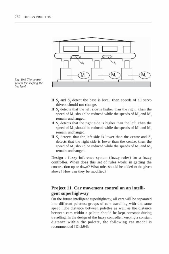
262 DESIGN PROJECTS
If S1 and S
2 detect the base is level, then speeds of all servo
drivers should not change.If S
1 detects that the left side is higher than the right, then the
speed of M1 should be reduced while the speeds of M
2 and M
3
remain unchanged.If S
2 detects that the right side is higher than the left, then the
speed of M3 should be reduced while the speeds of M
1 and M
2
remain unchanged.If S
1 detects that the left side is lower than the centre and S
2
detects that the right side is lower than the centre, then thespeed of M
2 should be reduced while the speeds of M
1 and M
3
remain unchanged.
Design a fuzzy inference system (fuzzy rules) for a fuzzycontroller. When does this set of rules work: in getting theconstruction up or down? What rules should be added to the givenabove? How can they be modified?
Project 11. Car movement control on an intelli-gent superhighwayOn the future intelligent superhighway, all cars will be separatedinto different palettes: groups of cars travelling with the samespeed. The distance between palettes as well as the distancebetween cars within a palette should be kept constant duringtravelling. In the design of the fuzzy controller, keeping a constantdistance within the palette, the following car model isrecommended [Dick94]:
Fig. 10.9 The controlsystem for keeping theflat level
CH10.PM5 6/18/97, 8:17 AM262
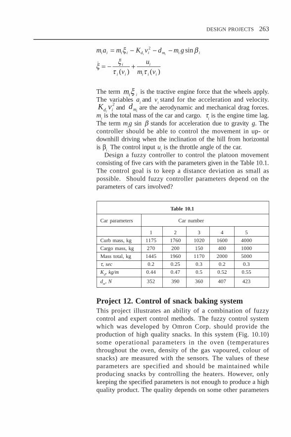
DESIGN PROJECTS 263
m a m K v d m g
v
u
m v
i i i i d i m i i
i
i i
i
i i i
i i= − − −
= − +
ξ β
ξ ξτ τ
2 sin
( ) ( )
The term miξ i is the tractive engine force that the wheels apply.
The variables ai and v
i stand for the acceleration and velocity.
K vd ii
2and dmi
are the aerodynamic and mechanical drag forces.m
i is the total mass of the car and cargo. τ
i is the engine time lag.
The term mig sin β stands for acceleration due to gravity g. The
controller should be able to control the movement in up- ordownhill driving when the inclination of the hill from horizontalis β
i . The control input u
i is the throttle angle of the car.
Design a fuzzy controller to control the platoon movementconsisting of five cars with the parameters given in the Table 10.1.The control goal is to keep a distance deviation as small aspossible. Should fuzzy controller parameters depend on theparameters of cars involved?
Table 10.1
Car parameters Car number
1 2 3 4 5
Curb mass, kg 1175 1760 1020 1600 4000
Cargo mass, kg 270 200 150 400 1000
Mass total, kg 1445 1960 1170 2000 5000
τ, sec 0.2 0.25 0.3 0.2 0.3
Kd, kg/m 0.44 0.47 0.5 0.52 0.55
dm, N 352 390 360 407 423
Project 12. Control of snack baking systemThis project illustrates an ability of a combination of fuzzycontrol and expert control methods. The fuzzy control systemwhich was developed by Omron Corp. should provide theproduction of high quality snacks. In this system (Fig. 10.10)some operational parameters in the oven (temperaturesthroughout the oven, density of the gas vapoured, colour ofsnacks) are measured with the sensors. The values of theseparameters are specified and should be maintained whileproducing snacks by controlling the heaters. However, onlykeeping the specified parameters is not enough to produce a highquality product. The quality depends on some other parameters
CH10.PM5 6/18/97, 8:17 AM263

264 DESIGN PROJECTS
which cannot be measured but may be evaluated by a humanexpert (operator). These data includes information aboutcracking, tough and thickness of products. The necessity forthese estimates, followed by their application in control process,requires the presence of highly qualified and experiencedoperators. The operators change the operational mode (heatercontrol) of baking depending on their evaluations of the product.
The rules applied by operators in control can be formulated andadded to other ‘conventional’ rules if a control system is designedwith fuzzy methods. E.g., if thickness is too small then increasethe power for heater No. 3 a little bit. The source for these rulescan be the technological process knowledge.
Design a fuzzy controller providing the specified values for theproduct parameters measured and include some rules formulatedon the base of the supposed technological process knowledge.
Project 13. Fuzzy GA controller for a refrigeratorA refrigerator with a structure that includes a fuzzy controller wasdeveloped at Samsung Electronics in 1991. This controllerestimates the food temperature with the help of some fuzzy rulesbased on measurement results of the inside temperature, theoutside temperature and the door opening/closing time. The goalof the fuzzy controller is to adjust the fan and the compressor toextend the percentage of time when the refrigerator works withoutconsuming electricity, providing the required temperature mode.The food temperature mode is specified with fuzzy terms.
Design a fuzzy controller to solve this problem. Apply geneticalgorithms (GA) to learn the fuzzy inference rules for temperaturederivation based on the data supplied.
Fig. 10.10 Fuzzy-expertcontrol of the bakingprocess
CH10.PM5 6/18/97, 8:17 AM264

DESIGN PROJECTS 265
Project 14. Fuzzy GA controller for invertedpendulum controlThis problem is so famous that it does not need any description.It has become a test design for fuzzy control. A fuzzy PD-likefuzzy controller is supposed to be designed with the angle errorand the changing rate of it as the controller inputs. The rule tableis similar to the one given in Section 3.5.3. GA are to be appliedfor the adjustment of the membership functions. The triangularmembership functions are proposed, with any one determined bythe set of three parameters (P,Q,R), see Fig. 10.12.
This set determines the shape of the membership function foreach linguistic variable. They have to be adjusted with GA toimprove the overall system response. Based on the experience in[Huang95] the parameters of GA could be advised as following:
Population size: 100Number of generations: 5Crossover rate: 0.8Mutation rate: 0.001
Fig. 10.11 Fuzzycontrolled fridge
Fig. 10.12. Three-parameter membershipfunction
CH10.PM5 6/18/97, 8:18 AM265

266 DESIGN PROJECTS
Project 15. Flip-flop electronic circuit for fuzzyoperation realisationFuzzy logic can be characterised as an extension of two-valuedBoolean logic, where NOT, AND and OR operators are extendedto fuzzy negation, t norm and s norm, respectively. In this case,the fundamental fuzzy logical circuits can be considered as oneof the fuzzy extensions of a combinatorial circuit in two-valuedBoolean logic. In such a situation, the concept of a fuzzyextension of a sequential circuit, which is the complex of acombinatorial circuit and memory modules in two-valued Booleanlogic should be discussed. So the concept of fuzzy flip-flopappears. It is a fuzzy extension of two-valued J–K flip-flop.
Design a fuzzy logic circuit for implementing fuzzy operationslike negation, t norm, and s norm based on a conventional flip-flop circuit.
CH10.PM5 6/18/97, 8:18 AM266

GLOSSARY 267
GLOSSARY
Adaptive Controller changing the control signal andcontroller the parameters of itself depending on the
changeable plant and environment model
Antecedent An initial part of a rule which determinespart of a rule the conditions under which the rule is fired
Applicability A degree in which all antecedent parts of adegree rule correspond to it
Backpropagation A method of recalculating the weight factorsmethod in ANN, based on propagation of the error
value from the output level back to the inputlevels and analysis of any weight influenceon the error value
Boolean logic A binary-type logic where any variable mayhave two values only: true or false
Characteristic The function which determines a set havingfunction the value of unity for all elements of the set
and zero for all others
Consequent part A final part of the rule which determinesof a rule what will happen if the rule is fired
Control surface A plot (usually three-dimensional) whichvirtually presents how the controller outputdepends on the inputs. Frequently used toestimate the controller quality
Clipping a fuzzy Cutting the degree of all the elements on theset specified level
GLOSS.PM5 6/12/97, 1:20 PM267

268 GLOSSARY
Crisp A collection of objects of any kind. In fuzzy(conventional) set set theory, it can be considered a specific
type of the fuzzy set with a membershipfunction having the value of unity for theelements of the crip set and zero for others
Defuzzification A process of producing a crisp output on thebase of a fuzzy input. Different defuzzificationmethods have been developed and applied
Extension principle The rule defining the fuzzy set on theuniverse which has functional relationshipwith the initial universes. Serves as a base forthe determination of the algebraic operationswith fuzzy sets (see Definitions 2.11 and 2.12)
Feedback structure The structure which assumes the applicationof the output signal at the structure inputtogether with the input signals. The mostfrequently applied in control systems, allowsa comparison of the real value of the outputwith the specified one
Fuzzification A process of producing a fuzzy input on thebase of a crisp one.
Fuzzy (logic) A control sys tem which impl ies thecontroller methodology of fuzzy logic. This type of
controller includes a knowledge-basedsystem consisting of fuzzy rules and aspecial mechanism of their processing (seeInference engine) as its main parts
Fuzzy logic There is a narrow and a broad sense of thisterm. In its narrow sense, fuzzy logic is asystem of logical operators defined by acalculus of interaction, that attempts toconstruct a model for the various modes ofhuman reasoning, which are approximaterather than exact. In its broad sense, fuzzylogic refers to a general class of fuzzy settheories, describing a family of classes withunsharp fuzzy boundaries
GLOSS.PM5 6/12/97, 1:20 PM268

GLOSSARY 269
Fuzzy number A fuzzified real number. See Definition 2.13
Fuzzy relation A relation of two (or in a general case n)fuzzy sets (see Definition 2.16). Applied inrules processing
Fuzzy rule A rule of the If ... then structure with vaguepredicates
Fuzzy set A set of ordered pairs, consisting of anelement of the universe of discourse and themembership degree. Any element of theuniverse belongs to a fuzzy set with somedegree only
Inference engine The specified process transforming fuzzy(mechanism) inputs into a fuzzy output by dealing with
fuzzy rules, as a result of which the responsecorresponding to the inputs is produced.Different types of inference processing havebeen developed and applied
Level set (α-cut-set) The set containing all the elementsbelonging to the fuzzy set with some degreenot lower than α (see Definition 2.4)
Linguistic hedge A modifier (e.g., very, rather) which isapplied to change the membership functionof the primary term
Linguistic label The name of the specified fuzzy set on theuniverse of discourse (e.g., short, long,medium)
Linguistic variable A variable, with a (linguistic) value that is aword or a word sentence (see Section 2.4)
Mamdani-type A type of fuzzy inference in which theinference consequent of each rule is a linguistic
statement assigning a linguistic value to thevariable. Supposes a defuzzification of theoutput produced
GLOSS.PM5 6/12/97, 1:20 PM269

270 GLOSSARY
Membership A number between 0 and 1, characterisingdegree the degree to which the element of the
universe belongs to the fuzzy set
Membership A function which corresponds a real numberfunction between 0 and 1 (which is called the
membership degree) to any generic elementof the universe of discourse. Themembership function determines a fuzzy set(see Definition 2.1)
Overshoot One of the performance indicatorstraditionally used in control engineering,especially while observing the controller unitstep response. Calculated as the increase ofthe response during the transient period overits final value
PID-controller The controller with an output that consists ofthree parts, with the first one proportional tothe input, the second one to the integral ofthe input, and the third one to the inputderivative. This controller type is the mostwidely applied in industry. It can be realisedas a PI-controller (when the derivative partis zero) or a PD-controller (when the integralpart is zero)
Range of values Several fuzzy sets would be defined withinassociated with a universe of discourse, each with its owna fuzzy variable domain which overlaps with the domains of
its neighbouring fuzzy sets
s norm See t conorm
Scaling a fuzzy set Scaling a membership degree of all theelements of the fuzzy set by multiplying itby a factor less than a unity
Scaling factors Coefficients by which the fuzzy controllerinputs and outputs are multiplied in order touse the normalised universe of discourse forinputs and outputs, that is the universe whichcoincides with the closed interval [–1,1]
GLOSS.PM5 6/12/97, 1:20 PM270
GLOSSARY 271
Self-organising Controller of which parameters are changedcontroller (tuned) without any changes in the plant model
Settling (settle) One of the performance indicators traditionallytime used in control engineering especially while
observing the controller unit step response.Calculated as the time period necessary forthe transient response to settle within thespecified strip around its final value
Singleton function A function which is unity at one particularpoint and zero everywhere else
Steady-state error One of the performance indicators traditionallyused in control engineering, especially whileobserving the controller unit step response.Calculated as the difference between thedesired final value of the response after thetransient period and the actual one
Sugeno-type A type of fuzzy inference, in which theinference consequent part of each rule is a linear
combination of the inputs. Does not involvea defuzzification process with the outputbeing calculated as a linear combination ofthe consequents. Sometimes is referred to asthe Takagi–Sugeno–Kang (TSK) method
Support The crisp subset of the universe, containing allthe elements belonging to the fuzzy set withsome non-zero degree (see Definition 2.2)
t conorm (also A two-input function with special featuresknown as s norm) (see Definition 2.10). Applied to determine
the union of two fuzzy sets
t norm (triangular A two-input function with special featuresnorm) (see Definition 2.8). Applied to determine
the intersection of two fuzzy sets
Transfer function A mathematical model which completelydescribes any element of the control system.Widely applied in controller analysis andsynthesis
GLOSS.PM5 6/12/97, 1:20 PM271

272 GLOSSARY
Truth value of a On a single-rule level, rule strength isrule usually determined by the truth of
antecedents of the rule. On a multiple-rulelevel, the rule strength of all rules bearing theconsequent is determined by the ruleevaluation process.
Tuning Changing some parameters and/or structurein order to improve some performanceindicators
Universe of The set which contains all the elementsdiscourse considered in the problem
TrademarksSome products that are referred to in the text and theircorresponding companies are given below:
AL220, INSIGHT IIe Adaptive LogicCubiCalc DataEngine HyperLogic
Management IntelligenterTechnologien (MIT) GmbH
FIDE AptronixfuzzyTECH, NeuroFuzzy, fuzzy PLC Inform GmbHFuzzyCalc FuzzyWareFlexFuzz MentaLogic SystemsFP-3000 OmronGIAC,SAAC,UNAC CICS AutomationMATLAB The MathWorksMATRIXx, SystemBuild, RT/Fuzzy Integrated SystemsMS-Windows, MS-Excel Microsoft Corp.TIL FPL, TILShell, FC110 Togai InfraLogicWARP SGS-Thomson
GLOSS.PM5 6/12/97, 1:20 PM272

BIBLIOGRAPHY 273
Bibliography
[Adams95] Adams G.J. and Goodwin G.C. ‘A MultivariableControl Design Toolbox.’ In: Proceedings of theInternational Conference ‘Control-95’,Melbourne, 20–24 October 1995, Institution ofEngineers, Australia, 1995, 1, pp. 193–197.
[Adap96] Advertising and explanation notes, World WideWeb home pages, Adaptive Logic, 1996.
[Ang95] Angstenberger J. ‘DataEngine – A SoftwareProduct Family for Intelligent Data Analysis.’In: Proceedings of the Third European Congresson Intelligent Techniques and Soft Computing(EUFIT’95), 29 August–1 September 1995,Aachen, Germany, 3, pp. 1892–6.
[Baek95] Baek W.-B., et al. ‘No-sway Crane OperatingControl System Development for UnmannedContainer Transporting.’ In: Fuzzy Logic for theApplications to Complex Systems Proceedings ofthe International Joint Conference of CFSA/IFIS/SOFT’95, 7–9 December 1995, Taipei, Taiwan,World Scientific Publishing, 1995, pp. 489–94
[Bald87] Baldwin S.F. ‘Energy Efficient Electric Motor-drive Systems.’ In: Electricity, ed. T.B. Johanssonet al., Lund University Press 1987.
[Ber92] Berenji H.R. and Khedkar P. ‘Learning andTuning Fuzzy Logic Controllers ThroughReinforcements.’ IEEE Transactions on NeuralNetworks, 3 (5), pp. 724–40, 1992.
BIBLIO.PM5 6/12/97, 1:21 PM273

274 BIBLIOGRAPHY
[Bour96] Bourmistrov A. and Reznik L. ‘Hybrid GuidanceControl for a Self-piloted Aircraft.’ In:Proceedings of the Conference: ‘Fuzzy Logic andManagement of Complexity (FLAMOC’96),’Sydney, Australia, 15–18 January 1996, 2, pp.155–9.
[Chiu95] Chiu S. ‘Software Tools for Fuzzy Control.’In: Industrial Applications of Fuzzy Logic andIntelligent Systems ed. J. Yen, R. Langari andL.A. Zadeh, IEEE Press, 1995, pp. 313–40.
[CICS96] Product Brochure, CICS Automation, Australia,1996.
[Clel92] Cleland J. ‘Fuzzy Logic Control of ACInduction Motors.’ In: Proceedings of IEEEInternational Conference on Fuzzy Systems, SanDiego, USA, March 1992, IEEE, 1992, pp.843–50.
[Cox94] Cox E. The Fuzzy Systems Handbook. APractitioner’s Guide to Building, Using, andMaintaining Fuzzy Systems. AP Professional,Cambridge, 1994.
[Dick94] Dickerson J.A. and Kosko B. ‘EllipsoidalLearning and Fuzzy Throttle Control for Platoonsof Smart Cars.’ In: Fuzzy Sets, Neural Networks,and Soft Computing, ed. R. Yager and L.A.Zadeh Van Nostrand Reinhold, New York, 1994,pp. 63–84.
[Drian93] Driankov D., Hellendoorn H. and Reinfrank M.An Introduction to Fuzzy Control, Springer-Verlag Berlin, Heidelberg, 1993.
[Far92] Farrell J. and Baker W. ‘Learning ControlSystems.’ In: An Introduction to Intelligent andAutonomous Control, ed. P.J. Antsaklis andK.M. Passino, Kluwer Academic, 1992, pp.237–62.
BIBLIO.PM5 6/12/97, 1:21 PM274

BIBLIOGRAPHY 275
[Fu64] Fu K. ‘Learning Control Systems.’ In: Computerand Information Sciences, ed. J. Tou and R.Wilcox, Spartan, 1964.
[Fuz92] Fuzzy Logic Educational Program, Center forEmerging Computer Technologies, MotorolaInc., 1992.
[Geb96] Gebhardt J. and von Altrock C. ‘Recent Success-ful Fuzzy Logic Applications in Industrial Auto-mation.’ In: Proceedings of the Fifth IEEEConference on Fuzzy Systems, September, NewOrleans, USA, IEEE Press, 1996.
[Ghan95-1] Ghanayem O. and Reznik L. ‘A New ReasoningApproach and its Application in Power SystemStability.’ In: Proceedings of the Third EuropeanCongress on Intelligent Techniques and SoftComputing (EUFIT’95), 29 August–1 September,1995, Aachen, Germany, 3, pp. 1527–32.
[Ghan95-2] Ghanayem O. and Reznik L. ‘A Hybrid AVR-PSS Controller Based on Fuzzy LogicTechnique.’ In: Proceedings of the InternationalConference ‘Control-95’, Melbourne, 20–24October 1995, Institution of Engineers,Australia, 1995, 2, pp. 347–51.
[Guo94] Guo S. and Peters L. ‘A Reconfigurable AnalogFuzzy Logic Controller.’ In: Proceedings of theThird IEEE Conference on Fuzzy Systems, 26–29 June, Orlando, USA, IEEE Press, 1994, 1,pp. 124–8.
[Guo95] Guo S. and Peters L. ‘A High-speed Recon-figurable Fuzzy Logic Controller.’ IEEE Micro,15 (6), 1995, p. 65.
[Har93] Harris C.J., Moore C.G. and Brown M.Intelligent Control: Aspects of Fuzzy Logic andNeural Nets, World Scientific., Singapore, 1993.
BIBLIO.PM5 6/12/97, 1:21 PM275

276 BIBLIOGRAPHY
[Hel94] Hellendooorn H. and Palm R. Fuzzy SystemTechnologies at Siemens R&D Fuzzy Sets andSystems, 63 (3), 1994, pp. 245–69.
[Hir93] Hirota K. (ed.), Industrial Applications of FuzzyTechnology, Springer-Verlag Tokyo, 1993.
[Hiy89] Hiyama, T. ‘Application of Rule BasedStabilising Controller to Electrical PowerSystem.’ IEE Proceedings-C, 136 (3), May1989, pp. 175–81.
[Hsu93] Hsu, Y. and Cheng, C. ‘A Fuzzy Controller forGenerator Excitation Control.’ IEEE Tran-sactions on Systems, Man and Cybernetics, 23(2), March/April 1993, pp. 532–9.
[Huang95] Huang S.-J. and Hung C.-C. ‘Genetic-evolvedFuzzy Systems for Inverted PendulumControls.’ In: Fuzzy Logic for the Applicationsto Complex Systems Proceedings of theInternational Joint Conference of CFSA/IFIS/SOFT’95, 7–9 December 1995, Taipei, Taiwan,World Scientific, 1995, pp. 35–40.
[Inn95] Innovation of the Year, EDN, 13 April 1995,p. 19.
[Ishig92] Ishigame A., Ueda T., et al. ‘Design of ElectricPower System Stabilizer Based on FuzzyControl Theory.’ IEEE Conference on FuzzySystems, 8–12 March, 1992, IEEE, 1992, pp.973–80.
[Jam94] Jamshidi M. ‘On Software and HardwareApplications of Fuzzy Logic.’ In: Fuzzy Sets,Neural Networks, and Soft Computing ed. RYager and L. A. Zadeh, Van Nostrand Reinhold,New York, 1994, pp. 396–430.
[Jang95] Jang J.-S.R. and Sun C.-T. ‘Neuro-fuzzyModelling and Control.’ Proceedings of theIEEE, 83 (3), March 1995, pp. 378–404.
BIBLIO.PM5 6/12/97, 1:21 PM276

BIBLIOGRAPHY 277
[Jar94] Jaramillo-Botero A. and Miyake Y. ‘A HighSpeed Parallel Architecture for Fuzzy Inferenceand Fuzzy Control of Multiple Processes.’ In:Proceedings of the Third IEEE Conference onFuzzy Systems, 26–29 June, Orlando, USA,IEEE Press, 1994, 3, pp. 1765–70.
[Kah95] Kahaner D.K. Fuzzy Control Applications inJapan, Asian Technology Information Program,Harks Roppongi Building, 1F, 6–15–21Rappongi, Tokyo, Japan.
[Kim95] Kim J., et al. ‘Industrial Applications ofIntelligent Control at Samsung Electronics Co.– In the Home Appliances Division.’ In: FuzzyLogic for the Applications to Complex SystemsProceedings of the International JointConference of CFSA/IFIS/SOFT’95, 7–9December 1995, Taipei, Taiwan, WorldScientific, 1995, pp. 478–82.
[Kre92] Kreinovich V., et al. ‘What Non-linearity toChoose? Mathematical Foundations of FuzzyControl.’ In: Proceedings of the 1992International Fuzzy Systems and IntelligentControl Conference, Louisville, KY, USA,1992, pp. 349–412.
[Krist92] Kristinsson K. and Dumont G.A. ‘SystemIdentification and Control Using GeneticAlgorithms.’ IEEE Transactions on Systems, Manand Cybernetics, 22 (5), 1992, pp. 1033–46.
[Kung93] Kung S.Y. Digital Neural Networks, PrenticeHall, Englewood Cliffs, 1993.
[Lea92] Lea R.N. and Chowdhury I. ‘Design andPerformance of the Fuzzy Tracking Controllerin Software Simulation.’ IEEE Conference onFuzzy Systems, 8–12 March 1992, IEEE, 1992,pp. 1123–30.
BIBLIO.PM5 6/12/97, 1:21 PM277

278 BIBLIOGRAPHY
[Lee90] Lee C.C. ‘Fuzzy Logic in Control Systems:Fuzzy Logic Controller.’ IEEE Transactions onSystems, Man and Cybernetics, 20 (2), 1990,pp. 404–35.
[Lin91] Lin C.-T. and Lee C.S.G. ‘Neural NetworkBased Fuzzy Logic Control and DecisionSystem.’ IEEE Transactions on Computers, 40(12), 1991, pp. 1320–36.
[Lin95] Lin C.-T. and Lu Ya-C. ‘A Neural Fuzzy Systemwith Linguistic Teaching Signals.’ IEEETransactions on Fuzzy Systems, 3 (2), 1995, pp.169–89.
[Link95] Linkens D.A. and Nyongesa H.O. ‘EvolutionaryLearning in Fuzzy Neural Control SystemsMethods for Autodesign of Systems based onSoft Computing Techniques and HumanPreference.’ In: Proceedings of the ThirdEuropean Congress on Intelligent Techniquesand Soft Computing, Aachen, Germany, 1995,1, pp. 990–5.
[Luo95] Luo J. and Lan E. ‘Fuzzy Logic Controllers forAircraft Flight Control.’ In: Fuzzy Logic andIntelligent Systems ed. H. Li and M. Gupta,Kluwer Academic, 1995, pp. 85–124.
[Mas94] Mason D.G., Linkens D.A., et al. ‘AutomatedDelivery of Muscle Relaxants using FuzzyLogic Control.’ IEEE Engineering in Medicineand Biology, 13 (5), 1994, pp. 678–86.
[McNeil 94] McNeil F.M. and Thro. F. Fuzzy Logic: APractical Approach, Boston. AP Professional,1994.
[Mik95] Miki T. and Yamakawa T. ‘Fuzzy Inference onan Analog Fuzzy Chip.’ IEEE Micro, 15 (5),October 1995.
[Nel91] Nelson M.M. and Illingworth W.T. A PracticalGuide to Neural Nets, Addison-Wesley, 1991.
BIBLIO.PM5 6/12/97, 1:21 PM278

BIBLIOGRAPHY 279
[Palm95] Palm R. ‘Scaling of Fuzzy Controllers Using theCross-correlation.’ IEEE Transactions on FuzzySystems, 3 (1), 1995, pp. 116–23.
[Pav92] Pavel L. and Chelaru M. ‘Neural Fuzzy Architec-ture for Adaptive Control.’ In: Proceedings ofIEEE International Conference on Fuzzy Systems,San Diego, USA, March 1992, IEEE, 1992, pp.1115–22.
[Polk93] Polkinghorne M.N., Roberts G.N. and BurnsR.S. ‘Small Marine Vessel Application of aFuzzy PID Autopilot.’ In: IFAC CongressProceedings, Sydney, 1993, 5, pp. 409–12.
[Pres95] Presberger T. and Koch M. ‘Comparison ofEvolutionary Strategies and Genetic Algorithmsfor Optimisation of a Fuzzy Controller.’Proceedings of the Third European Congress onIntelligent Techniques and Soft Computing,Aachen, Germany, 1995, 3, pp. 1850–6.
[Proc79] Procyk T.J. and Mamdani E.H. ‘A LinguisticSelf-organising Process Controller.’ Automatica,15 (1), 1979, pp. 15–30.
[Rez93] Reznik L. and Stoica A. ‘Some Tricks in FuzzyController Design.’ In: Proceedings of Australiaand New Zealand Conference on IntelligentInformation Systems, ANZIIS–93. IEEE, Perth,Western Australia, 1993, pp. 60–4
[Rez95-1] Reznik L. and Shi J. ‘Fuzzy Controller DesignFrom a Practitioner’s Point of View –Membership Function Choice.’ AustralianJournal of Intelligent Information ProcessingSystems, 2 (2), 1995, pp. 38–46.
[Rez95-2] Reznik L. and Little A. ‘Fuzzy ControllerDesign From a Practitioner’s Point of View –The Review of Methodologies.’ AustralianJournal of Intelligent Information ProcessingSystems, 2 (4), 1995, pp. 1–9
BIBLIO.PM5 6/12/97, 1:21 PM279

280 BIBLIOGRAPHY
[Sanz94] Sanz A. ‘Analog Implementation of FuzzyController.’ In: Proceedings of the Third IEEEConference on Fuzzy Systems, 26–29 June,Orlando, USA, IEEE Press, 1994, 1, pp. 279–83.
[Schw92] Schwartz D.G. and Klir G.J. ‘Fuzzy LogicFlowers in Japan.’ IEEE Spectrum, July 1992,pp. 32–5.
[Shi95] Shi J. ‘Development of a Fuzzy Logic Controlleras a Power System Stabiliser Using HierarchicalStructure.’ In: Industrial and EngineeringApplications of Artificial Intelligence and ExpertSystems. Proceedings of the Eighth InternationalConference, Melbourne, Australia, 6–8 June1995, pp. 401–9.
[Sil90] De Silva C.W. ‘Fuzzy Adaptation and Control ofa Class of Dynamic Systems.’ Proceedings of theFifth IEEE International Symposium on IntelligentControl, Philadelphia, 1990, pp. 304–9.
[Sur94] Surmann H., et al. ‘What Kind of Hardware isNecessary for a Fuzzy Rule Based System?’In: Proceedings of the Third IEEE Conferenceon Fuzzy Systems, 26–29 June, Orlando, USA,IEEE Press, 1994, 1, pp. 274–8.
[Tak91] Takagi H. and Hayashi I. ‘NN-driven FuzzyReasoning.’ International Journal of ApproximateReasoning, 5 (3), 1991, pp. 191–212.
[Tak95-1] Takagi H. ‘Methods for Autodesign of SystemsBased on Soft Computing Techniques andHuman Preference.’ In: Proceedings of theThird European Congress on IntelligentTechniques and Soft Computing, Aachen,Germany, 1995, 1, pp. 646–50.
[Tak95-2] Takagi H. ‘Applications of Neural Networks andFuzzy Logic to Consumer Products.’ In:Industrial Applications of Fuzzy Logic andIntelligent Systems, ed. J. Yen, R. Langari, L.Zadeh, IEEE Press, New York, 1995, pp. 93–105.
BIBLIO.PM5 6/12/97, 1:21 PM280

BIBLIOGRAPHY 281
[Tan95] Tanaka K. ‘Design of Fuzzy Controllers Based onFrequency and Transient Characteristics.’ In: FuzzyLogic and Intelligent Systems, ed. H. Li and M.Gupta, Kluwer Academic, 1995, pp. 187–212.
[Tang87] Tang K.L. and Mulholland R.J. ‘ComparingFuzzy Logic with Classical Controller Designs.’IEEE Transactions on Systems, Man andCybernetics, 1987, SMC-17 (6), pp. 1085–7.
[Tao94] Tao W. and Burkhardt H. ‘Application of FuzzyLogic and Neural Network to the Control of aFlame Process.’ In: Proceedings of the SecondIEE Conference on Intelligent SystemsEngineering, Hamburg, September 1994, IEE,London, 1994, pp. 235–40.
[Ter94] Terano T., et al. (ed.) Applied Fuzzy Systems.Academic Press, 1994.
[Tog86] Togai M. and Watanabe H. ‘Expert System ona Chip: an Engine for Real-time ApproximateReasoning.’ IEEE Expert Systems Magazine, 1,1986, pp. 55–62.
[Tsyp73] Tsypkin Y. Foundations of Learning Systems,Academic Press, 1973.
[Ung94] Ungering A.P. and Goser K. ‘Architecture of a64-bit Fuzzy Inference Processor.’ In:Proceedings of the Third IEEE Conference onFuzzy Systems, 26–29 June, Orlando, USA,IEEE Press, 1994, 3, pp. 1776–80.
[Wang94-1] Wang Li-Xin ‘A Supervisory Controller forFuzzy Control Systems that GuaranteesStability.’ IEEE Transactions on AutomaticControl, 39 (9), 1994, pp. 1845–7.
[Wang94-2] Wang Li-Xin. Adaptive Fuzzy Systems andControl: Design and Stability Analysis, PrenticeHall, Englewood Cliffs, 1994.
BIBLIO.PM5 6/12/97, 1:21 PM281

282 BIBLIOGRAPHY
[Wu96] Wu J.C. and Liu T.S. ‘A Sliding-mode Approachto Fuzzy Control Design.’ IEEE Transactions onControl System Technology, 4 (2), 1996, pp.141–51.
[Yag94] Yager R.R. and Filev D.P. Essentials of FuzzyModeling and Control, John Wiley, 1994.
[Yam86] Yamakawa T. and Miki T. ‘The Current ModeFuzzy Logic Integrated Circuits Fabricated bythe Standard CMOS Process.’ IEEETransactions on Computers, C-35 (2), 1986,pp. 161–7.
[Yas85] Yasunobu, S. et al. ‘Automatic Train OperationSystem by Predictive Fuzzy Control.’ In:Industrial Applications of Fuzzy Control ed. M.Sugeno, Elsevier (N. Holland), 1985, pp. 1–18.
[Yen92] Yen J-Y., Lin C.-S., et al. ‘Servo ControllerDesign for an Optical Disk Drive using FuzzyControl Algorithm.’ IEEE Conference on FuzzySystems, 8–12 March, 1992, IEEE, pp. 989–97.
BIBLIO.PM5 6/12/97, 1:21 PM282

INDEX 285
Index
Terms marked with an asterisk are included in the Glossary (see Chapter 11)
Adaptive control*, 73, 156–158, 176Adjustment, see TuningANN, see Neural networkAntecedent, 65–67, 78, 146, 212Applicability degree*, 67–69, 72–73Arithmetic fuzzy, 41–43, 203–204
Boolean*, 5, 21, 24
Characteristic function*, 20, 23Clipping*, 65, 68, 69, 147Closed loop, see FeedbackCode, program, 191, 196, 197, 200Complement, 22–24, 29, 45Consequent*, 65–67, 78, 212Control conventional, limitations, 4, 15, 16, 59Crisp set*, 19, 37, 193
definition, 21Crossover point, 26, 180, 182Cut set, see Level set
Defuzzification*, 74, 147–152, 211Discrimination, 21–22Disturbance (noise), 108–111, 134
Educational tools, 190, 193Evolutionary algorithms, 182–183Extension principle*, 34–36, 39
Feedback*, 79, 117, 123, 129, 159, 176Fuzzification*, 67Fuzzy associative memory, 198Fuzzy control application, 64
airspace engineering, 11, 13–15, 91–93,129–130, 184–185
automotive engineering, 9, 11, 12, 145bioengineering, 137–139consumer products, 9, 11, 75–77, 177–179
engine and boiler, 60–62environment engineering, 176financial, 18heater, 112–116induction motor, 142–143, 160–162power engineering, 100–101, 163–166servo drive, 102steam turbine, 88telecommunication engineering, 117–121temperature control, 135transport engineering, 11, 16–18, 107–111,
135, 141–144Fuzzy control benefits, 5, 15, 60, 89Fuzzy controller,
combined fuzzy – PID, 91–93design, 74, 115, 121–123, 127
CAD packages, 132, 187–200features, 190–200
hierarchical, 99–100operation, 15, 73–74, 92, 113–116, 163–165implementation, 15, 201–216learning, 157–160neuro-fuzzy, 174–179performance, 94–97, 101, 141, 144,
154–155, 159robustness, 154–155self-organising, 138, 154, 156–158,
160–166stability, 94–95, 98, 101, 126structure, 75–77, 79, 84, 85, 88, 100, 126,
155, 157supervisory, 99–101
Fuzzy coprocessor, 208Fuzzy inference, see Fuzzy processingFuzzy logic*, 3, 5, 10, 11Fuzzy number*, 37–43Fuzzy processing*,
Mamdani type, 61–73, 213
INDEX.PM5 6/12/97, 1:22 PM285

286 INDEX
Fuzzy processing*(continued)Sugeno type, 70–73, 147
Fuzzy processor, 196, 202–214analog, 202, 211–214digital general purpose, 202–204
increasing performance, 203–204specialised, 202, 205–209
AL220 by Adaptive logic, 206–207FC110 by Togai InfraLogic, 203–205,
210WARP by SGS-Thomson, 207–208development system, 209–210
Fuzzy relation*, see Relation, fuzzyFuzzy rule*, see Rule, fuzzyFuzzy set*, 3, 25, 40, 63
convex, 38definition, 25normal, 38
General Motors, 11, 12Genetic algorithms, 180–185
Hardware tools, 199–216Hedge,
approximation, 46–50concentration, 46–50linguistic*, 46–50dilution, 46–50
Height, fuzzy set, 29, 151
Inference engine*, see Fuzzy processingIntersection, 22–24, 29, 31–34, 45, 55, 141Interval, 37–40
Kahaner, David, 12
Language, natural, 5, 10, 44–51Level set*, 28, 38Liapunov, 96Linguistic label*, 29–30, 77Linguistic value, 44, 63, 68, 75, 79, 80Linguistic variable*, 63, 68, 75, 137, 143List method of set definition, 29
Mamdani, Ebrahim, 8, 60–62MATRIXx*, 108–111, 135–136, 160, 187,
189, 192Matsushita, 9, 10, 177–178Membership degree*, 25, 35, 72Membership function*, 25, 37, 48, 56, 63–65,
88, 140, 197, 212–213choice, 131–135, 182
gaussian, 27, 43, 133, 135quadratic, 27shape, 26–28, 46, 126, 183trapezoidal, 27, 42–43triangular, 27, 42, 134
Mitsubishi, 9, 12Modelling, 4, 16, 51, 60, 108–111, 135, 136,
142, 160, 176, 187, 191, 196, 197, 199Motorola, 8, 187, 189Multirelational composition, 54
Neural network, 167–180back propagation*, 172–173layer, 170, 175, 177processing element, 168–170threshold, 168–169
Neuro-fuzzy, 174–179, 198ANFIS, 175–176
Nonlinearity, 4, 15, 60, 61, 88, 155, 170
Omron, 8, 11, 207–208Operations on fuzzy sets, 22, 29, 41, 52Overshoot*, 96, 134, 161
Panasonic, see MatsushitaPerformance indicator, 96–97, 164, 165PID control*, 5, 16, 78, 90–91, 107, 127,
131PD-like fuzzy controller, 79–83, 123,
138–139PI-like fuzzy controller, 84–86, 127–128PID-like fuzzy controller, 86, 87, 88, 160PLC, fuzzy, 196, 214–216Predictive fuzzy control, 16–19, 90
Relation, fuzzy, 51–57Rule, fuzzy, 51, 54, 61, 64–66, 69, 87, 92,
113–115, 139, 143formulation, 136–139, 182
Rules table, 61, 76, 81–83, 85, 86, 89, 93, 102,114, 120, 139, 144, 165
Scaling factors*, 103, 124–130, 160–166Scaling fuzzy set*, 69, 147Set point, 61, 79–83Settling time*, 96, 134, 161Siemens, 8, 145, 189S-norm, 33–34, 67Software tools, 187–200Steady-state error, 134, 161Sugeno processing*, see Fuzzy processing
Sugeno-type support*, 26
INDEX.PM5 6/12/97, 1:22 PM286

INDEX 287
Terano, Toshiro, 3, 7Togai, Masaki, 8, 193, 203–205, 209Transfer function*, 168–169T-norm, 30–34, 53, 68, 175Triangular norm, see T-normTriangular conorm, see S-normTuning*, 97, 126, 153, 159–185
Uncertainty, 4, 155Union, 22–24, 31–34, 45, 56, 70
Universal set, see Universe of discourseUniverse of discourse*, 19–21, 52, 124–126, 131
Watanabe, Hiroyuke, 8Whole overlap, index of, 133–136
Yamakawa, Takeshi, 8, 211
Zadeh, Lotfi, 4–8Zimmermann, Hans, 8, 191
INDEX.PM5 6/12/97, 1:22 PM287

288 INDEX
INDEX.PM5 6/12/97, 1:22 PM288