fusion manual - isco industries
TRANSCRIPT
Table of Contents
This manual contains accurate and reliable information tothe best of our knowledge as of the publication date. Theresults of using our suggestions and recommendations can-not be guaranteed because the conditions of use arebeyond our control. Failure to follow these procedures inthis manual may result in damage to or destruction ofproperty and/or serious injury to or death of a person. Theuser of such information assumes all risk connected withthe use thereof. ISCO Industries, LLC assumes no respon-sibility for the use of information presented herein andhereby disclaims all liability in regard to such use.
ISCO Fusion Manual
3
Fusion Equipment Safety Information . . . . . . . . Page 4
Tips For Success . . . . . . . . . . . . . . . . . . . . . . . . . . . . . Page 15
Manual Butt Fusion Machine Procedure . . . . . . . Page 18
Hydraulic Butt Fusion Machine Procedure . . . . . Page 31
Saddle Fusion Machine Procedure . . . . . . . . . . . Page 48
Socket Tooling and Fusion Procedure . . . . . . . . . Page 60
Reference Information: McElroy’s DataLogger™, Pendant/Coach™
Equipment & Fusion Pressure Charts . . . . . . . . . . Page 69
© Copyright 2007 ISCO Industries, LLC All rights reserved.

4© Copyright 2007 ISCO Industries, LLC All rights reserved.
Fusion EquipmentSafety Information
Please read theSafety Section
first.How was I suppose to
know?

Safety Alerts
This hazard alert sign appears in this manual.When you see this sign, carefully read what it says.YOUR SAFETY IS AT STAKE.
You will see the hazard alert sign with these words:DANGER, WARNING, and CAUTION.
In this manual you should look for two other words:NOTICE and IMPORTANT.
NNOOTTIICCEE:: Can keep you from doing something that mightdamage the machine or someone’s property. It may also be used to alert against unsafe practices.
IIMMPPOORRTTAANNTT:: Can help you do a better job or make your job easier in some way.
!
ISCO Fusion Manual
5© Copyright 2007 ISCO Industries, LLC All rights reserved.
!! DANGER
! WARNING
! CAUTION
! DANGER
WARNING!
CAUTION! Indicates a hazardous situation which,if not avoided, may result in minor ormoderate injury.
Indicates a potentially hazardoussituation which, if not avoided, couldresult in death or serious injury.
Indicates an imminently hazardoussituation which, if not avoided, willresult in death or serious injury.
Read And Understand
Do not operate fusion equipment until youhave carefully read, and understand the“Safety” and “Operation” sections of thismanual, and all other equipment manualsthat will be used with it.
Your safety and the safety of others dependsupon care and judgement in the operationof this equipment.
Follow all applicable federal, state, local,and industry specific regulations.
Fusion Equipment Safety Information

ISCO Fusion Manual
6© Copyright 2007 ISCO Industries, LLC All rights reserved.
ISCO Industries, LLC cannot anticipate every possible circumstance that may involve a potential hazard. The warnings in this manualand on the machine are therefore not all inclusive. You must satisfy yourself that a procedure, tool,work method, or operating technique is safe foryou and others. You should also ensure that the machine will not be damaged or made unsafe by the method of operation or maintenance you choose.
General SafetySafety is important. Report anything unusual that you notice during set up or operation.
LLiisstteenn for thumps, bumps, rattles, squeals, airleaks, or unusual sounds.
SSmmeellll odors like burning insulation, hot metal,burning rubber, hot oil, or natural gas.
SSeennssee any changes in the way the equipment operates.
SSeeee problems with wiring and cables, hydraulicconnections, or other equipment.
Report anything you see, feel, smell, or hear that is different from what youexpect, or that you think may be unsafe.
Wear Safety EquipmentWear a hard hat, safety shoes, safety glasses,and other applicable personal protectionequipment.
Remove jewelry and rings, and do not wearloose-fitting clothing or long hair that couldcatch on controls or moving machinery.
Fusion Equipment Safety Information
ISCO Fusion Manual
7© Copyright 2007 ISCO Industries, LLC All rights reserved.
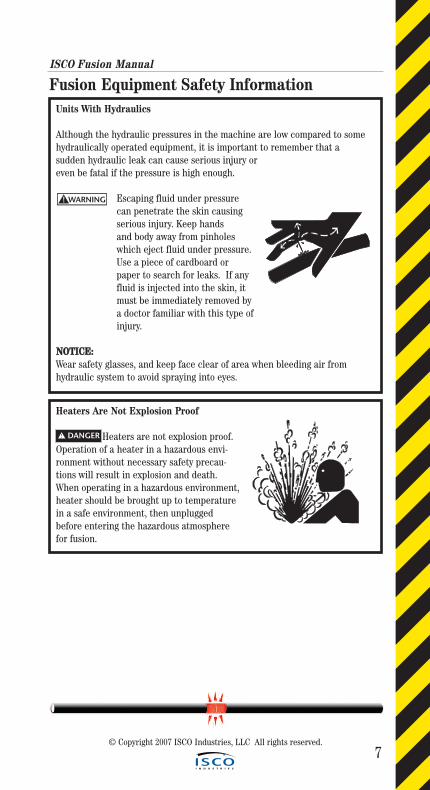
Fusion Equipment Safety InformationUnits With Hydraulics
Although the hydraulic pressures in the machine are low compared to somehydraulically operated equipment, it is important to remember that a sudden hydraulic leak can cause serious injury or even be fatal if the pressure is high enough.
Escaping fluid under pressurecan penetrate the skin causing serious injury. Keep handsand body away from pinholes which eject fluid under pressure. Use a piece of cardboard or paper to search for leaks. If any fluid is injected into the skin, it must be immediately removed by a doctor familiar with this type of injury.
NNOOTTIICCEE:: Wear safety glasses, and keep face clear of area when bleeding air fromhydraulic system to avoid spraying into eyes.
WARNING!
Heaters Are Not Explosion Proof
Heaters are not explosion proof.Operation of a heater in a hazardous envi-ronment without necessary safety precau-tions will result in explosion and death.When operating in a hazardous environment,heater should be brought up to temperaturein a safe environment, then unpluggedbefore entering the hazardous atmospherefor fusion.
! DANGER

ISCO Fusion Manual
8© Copyright 2007 ISCO Industries, LLC All rights reserved.
Fusion Equipment Safety InformationElectric Motors Are Not Explosion Proof
Electric Motors are not explo-sion proof. Operation of these componentsin a hazardous environment without neces-sary safety precautions will result in explo-sion or death. When operating in a haz-ardous environment, keep pump motorand chassis in a safe area by usinghydraulic extension hoses.
Electrical Safety
Always ensure power cords are properly grounded. It is important to remember that whenyou are working in a wet environment withelectrical devices, proper ground connectionshelp to minimize the chances of an electric shock.
Frequently inspect electrical cords and unit for damage. Damaged components need to replacedand service performed by a qualified electrician.Do not carry electrical devices by the cord.
NNOOTTIICCEE:: Always connect units to the proper power sourceas listed on the unit, or in the owner’s manual. Onunits with two power cords, plug each cord intoseparate power circuits. Do not plug into both out-lets of one duplex receptacle.
NNOOTTIICCEE:: Disconnect the machine from the power sourcebefore attempting any maintenance or adjustment.
! DANGER
WARNING!
ISCO Fusion Manual
9© Copyright 2007 ISCO Industries, LLC All rights reserved.
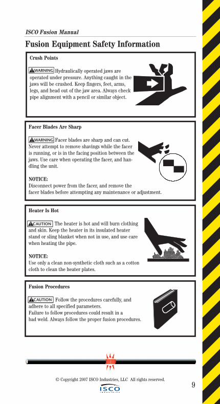
Fusion Equipment Safety InformationCrush Points
Hydraulically operated jaws areoperated under pressure. Anything caught in thejaws will be crushed. Keep fingers, feet, arms,legs, and head out of the jaw area. Always checkpipe alignment with a pencil or similar object.
Facer Blades Are Sharp
Facer blades are sharp and can cut.Never attempt to remove shavings while the faceris running, or is in the facing position between thejaws. Use care when operating the facer, and han-dling the unit.
NOTICE: Disconnect power from the facer, and remove thefacer blades before attempting any maintenance or adjustment.
Heater Is Hot
The heater is hot and will burn clothingand skin. Keep the heater in its insulated heaterstand or sling blanket when not in use, and use carewhen heating the pipe.
NOTICE:Use only a clean non-synthetic cloth such as a cottoncloth to clean the heater plates.
Fusion Procedures
Follow the procedures carefully, andadhere to all specified parameters.Failure to follow procedures could result in a bad weld. Always follow the proper fusion procedures.
WARNING!
WARNING!
CAUTION!
CAUTION!
ISCO Fusion Manual
10© Copyright 2007 ISCO Industries, LLC All rights reserved.
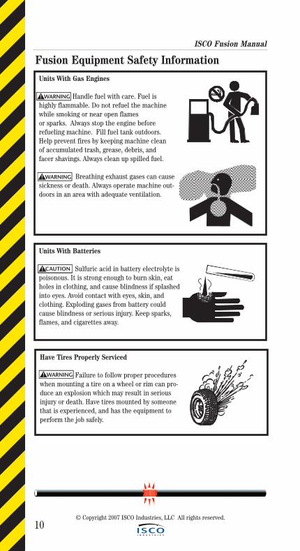
Fusion Equipment Safety InformationUnits With Gas Engines
Handle fuel with care. Fuel ishighly flammable. Do not refuel the machinewhile smoking or near open flames or sparks. Always stop the engine before refueling machine. Fill fuel tank outdoors.Help prevent fires by keeping machine cleanof accumulated trash, grease, debris, and facer shavings. Always clean up spilled fuel.
Breathing exhaust gases can causesickness or death. Always operate machine out-doors in an area with adequate ventilation.
Units With Batteries
Sulfuric acid in battery electrolyte ispoisonous. It is strong enough to burn skin, eatholes in clothing, and cause blindness if splashedinto eyes. Avoid contact with eyes, skin, andclothing. Exploding gases from battery couldcause blindness or serious injury. Keep sparks,flames, and cigarettes away.
Have Tires Properly Serviced
Failure to follow proper procedureswhen mounting a tire on a wheel or rim can pro-duce an explosion which may result in seriousinjury or death. Have tires mounted by someonethat is experienced, and has the equipment toperform the job safely.
WARNING!
CAUTION!
WARNING!
WARNING!
ISCO Fusion Manual
11© Copyright 2007 ISCO Industries, LLC All rights reserved.
Fusion Equipment Safety Information
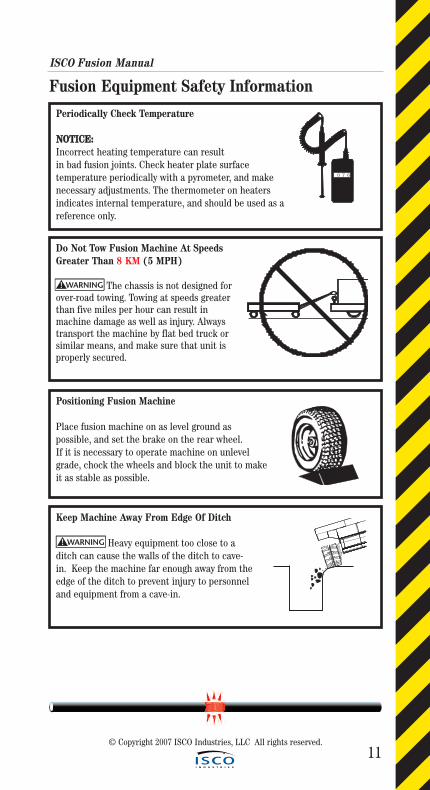
Periodically Check Temperature
NNOOTTIICCEE::Incorrect heating temperature can resultin bad fusion joints. Check heater plate surface temperature periodically with a pyrometer, and makenecessary adjustments. The thermometer on heatersindicates internal temperature, and should be used as areference only.
0 7 6
Do Not Tow Fusion Machine At SpeedsGreater Than 8 KM (5 MPH)
The chassis is not designed forover-road towing. Towing at speeds greaterthan five miles per hour can result inmachine damage as well as injury. Alwaystransport the machine by flat bed truck orsimilar means, and make sure that unit isproperly secured.
Positioning Fusion Machine
Place fusion machine on as level ground as possible, and set the brake on the rear wheel.If it is necessary to operate machine on unlevelgrade, chock the wheels and block the unit to makeit as stable as possible.
Keep Machine Away From Edge Of Ditch
Heavy equipment too close to a ditch can cause the walls of the ditch to cave-in. Keep the machine far enough away from the edge of the ditch to prevent injury to personneland equipment from a cave-in.
WARNING!
WARNING!
ISCO Fusion Manual
12
Fusion Equipment Safety Information
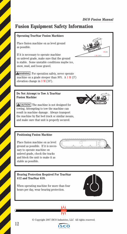
Do Not Attempt to Tow A TracStar Fusion Machine
The machine is not designed fortowing. Attempting to tow the machine canresult in machine damage. Always transport the machine by flat bed truck or similar means,and make sure that unit is properly secured.
Operating TracStar Fusion Machines
Place fusion machine on as level groundas possible.
If it is necessary to operate machine on unlevel grade, make sure that the ground is stable. Some unstable conditions maybe ice,snow, mud, and loose gravel.
For operation safety, never operatemachine on a grade steeper than 30%. A 1 M (3’) elevation change in 3 M (10’).
Positioning Fusion Machine
Place fusion machine on as levelground as possible. If it is neces-sary to operate machine on unlevel grade, chock the tracksand block the unit to make it asstable as possible.
WARNING!
CAUTION!
Hearing Protection Required For TracStar412 and TracStar 618.
When operating machine for more than four hours per day, wear hearing protection.
0100
200
300
400500 600
700
800
900
1000
DIRECTIONALCONTROLVALVE
FACING
PRESSURE
HEATING
PRESSURE
FUSING
PRESSURE
SELECTOR
VALVE
3 M (10’)
1M (3’)
0
1 0 0
2 0 0
3 0 0
4 0 0 5 0 0 6 0 0
7 0 0
8 0 0
9 0 0
1 0 0 0
D IR E C T IO N A LC O N T R O L
V A L V E
F A C I N G
P R E S S U R E
H E A T I N G
P R E S S U R E
F U S I N G
P R E S S U R E
S E L E C T O R
V A L V E
© Copyright 2007 ISCO Industries, LLC All rights reserved.
ISCO Fusion Manual
13
Fusion Equipment Safety Information
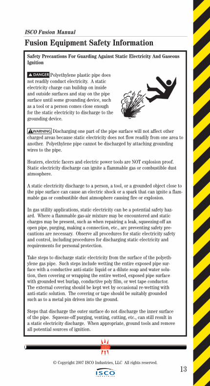
Safety Precautions For Guarding Against Static Electricity And GaseousIgnition
Polyethylene plastic pipe doesnot readily conduct electricity. A staticelectricity charge can buildup on insideand outside surfaces and stay on the pipesurface until some grounding device, suchas a tool or a person comes close enoughfor the static electricity to discharge to thegrounding device.
Discharging one part of the pipe surface will not affect othercharged areas because static electricity does not flow readily from one area toanother. Polyethylene pipe cannot be discharged by attaching groundingwires to the pipe.
Heaters, electric facers and electric power tools are NOT explosion proof.Static electricity discharge can ignite a flammable gas or combustible dustatmosphere.
A static electricity discharge to a person, a tool, or a grounded object close tothe pipe surface can cause an electric shock or a spark that can ignite a flam-mable gas or combustible dust atmosphere causing fire or explosion.
In gas utility applications, static electricity can be a potential safety haz-ard. Where a flammable gas-air mixture may be encountered and static charges may be present, such as when repairing a leak, squeezing-off an open pipe, purging, making a connection, etc., arc preventing safety pre-cautions are necessary. Observe all procedures for static electricity safety and control, including procedures for discharging static electricity and requirements for personal protection.
Take steps to discharge static electricity from the surface of the polyeth-ylene gas pipe. Such steps include wetting the entire exposed pipe sur-face with a conductive anti-static liquid or a dilute soap and water solu-tion, then covering or wrapping the entire wetted, exposed pipe surface with grounded wet burlap, conductive poly film, or wet tape conductor. The external covering should be kept wet by occasional re-wetting with anti-static solution. The covering or tape should be suitably grounded such as to a metal pin driven into the ground.
Steps that discharge the outer surface do not discharge the inner surface of the pipe. Squeeze-off purging, venting, cutting, etc., can still result in a static electricity discharge. When appropriate, ground tools and remove all potential sources of ignition.
WARNING!
! DANGER
© Copyright 2007 ISCO Industries, LLC All rights reserved.

ISCO Fusion Manual
14
Fusion Equipment Safety InformationSafety Precautions For Guarding Against Static Electricity And GaseousIgnition (Continued)
Key items:
Do not put a butt fusion machine chassis in a hazardous environment. Set the chassis up out of harms way and use extension hoses to operate upper works in hazardous area.
Do not use a butt fusion machine with an electric facer in a gaseous environment. Use a machine equipped with a hydraulic facer or convert the electric facer to a manual by removing the brushes and turning facer manually.
When making butt fusions, saddle fusions and socket fusions in a haz-ardous environment, set the generator up out of harms way and have the heater plugged into it there. Set the heater temperature at the maximumallowed for the application. Use 232° C (450° F) for butt fusion and 266°C (510° F) for saddle fusion and socket fusion. These are surface temperatures. The high side temperatures are used to compensate for the drop in temperature experienced when heater is unplugged from the power source to make fusion in hazardous area. Unplug heater prior to using in a hazardous environment.
Do not drill hole first prior to making a saddle fusion.
When prepping the main pipe for a saddle fusion, do not use an electric grinding tool. Prepare main pipe manually by use of 50-60 grit utility cloth.
Do not use an electric drill for punching hole through after saddle fusion has been made.
Use your senses and good judgment: Listen, Smell, Feel, See and Report any unsafe situations you see or see coming to your onsite contact, if corrective action is not taken in your opinion, Do not enter into the situation.
© Copyright 2007 ISCO Industries, LLC All rights reserved.

15© Copyright 2007 ISCO Industries, LLC All rights reserved.
Tips For Success
What can I learn from others before getting
started?
Tip
s fo
r Su
cces
s
16
Tips fo
r Success
ISCO Fusion Manual
Use Personal Safety Equipment. Always wear a hard hat and protective boots. Gloves protect hands from heater burns and sharp blades on the facer. Protective Eye Glasses are also a good idea.
Make sure all equipment is in good working order and power cords are free of cuts with grounding blade on receptacle in tack.
Position fusion equipment on level ground whenever possible.
If the fusion equipment has wheels, set the wheel lock or block them.
Position pipe support stands on either side of the fusion equipment approximately 6 M (20') from ends of the fusion equipment. Adjust stands so that pipes are level to reduce drag.
When working with McElroy Self-Contained fusion units excluding the T-500 and T-900, make sure to open the facer valve prior to starting theunit and keep it open until started. Close valve once unit is running.This will save the battery and keep you from burning up the starter.
Plug heater in on self-contained fusion units only after unit has been started and warmed up. Unplug heater before turning fusion unit off. This will keep you from having heater element and circuitry problems with your heater.
Load loose pipe joints into movable side of the fusion equipment and pull joints already fused through non-movable side.
Check your pipe before you fuse it. Look for deep scratches, cuts and gouges. Use the 10 percent rule: Any imperfection affecting more than 10 percent of the pipe wall being worked with should not be used.
When rough cutting pipe, use a pipe wrap to mark the pipe with a refer-ence line, this will aid you in making a square and even cut. In general, tooling that works with wood works well with HDPE pipe. For cutting pipe, skill saws and chain saws work well. When using chain saws, the cut ends MUST be cleaned with isopropyl alcohol to remove BAR Oil Splash or any other contaminants. For cutting holes in pipe, drills with hole saws and reciprocating saws work well.
When making fusions that involve pipe to fittings, special care should be taken. The necking down or toe in at the pipe ends, which is nor-mal, needs to be completely removed in the facing process. This is seen primarily in working with the larger pipe diameters.
Do not abuse the facer when facing pipes by using too much pressure.
When pulling pipe through the fusion equipment, elevate pipe in the machine using the pipe lifts so the fusion bead clears all obstructions asit is pulled through.
© Copyright 2007 ISCO Industries, LLC All rights reserved.
Tips for Success
© Copyright 2007 ISCO Industries, LLC All rights reserved.
Tip
s fo
r Su
cces
s
ISCO Fusion Manual
17
Tips for Success (Continued)If a fusion weld does not come out exactly as you like or you question the quality of the fusion weld, then cut it out and re-fuse. Always remember – IF IN DOUBT, CUT IT OUT and redo.
Fusion beads can be removed by means of external and internal bead removers without effecting the integrity of the fusion joint.
In inclement weather and especially in windy conditions, the fusion operation should be shielded to avoid precipitation or blowing snow andexcessive heat loss from wind chill. Capping ends of pipe that are being fused aides heater from being chilled as fusion joint is being made.
The joint area and its parts that are being fused must be completely dry.No liquid of any kind running through the pipe or fittings is permissible.
When fusion is done in cold weather, DO NOT INCREASE HEATING TOOL SURFACE TEMPERATURE.
Do not try to shorten cooling times of fusions by applying wet cloths, water or the like.
When removing pipe from the fusing unit and pulling into place, use proper lifting slings and pulling heads in good condition. Chains and rope can slip and cause injury/damage to personnel and pipe.
When working with coiled pipe 63 mm-160 mm (2" - 6"), a McElroy LineTamer™ should be used to straighten and reround coiled pipe to meet or exceed ASTM D-2513 Quality Requirements.
Squeeze tools can be used on HDPE Pipe to stop flow in a pipeline while a tie in or repair is made. Follow manufacturer’s squeeze-off tool instructions.
A common obstacle when working with HDPE pipe in the field is under-standing the thermal expansion and contraction. Rule of thumb - 2 cm/10 M/10°C (1.4"/ 100'/ 10ºF.)
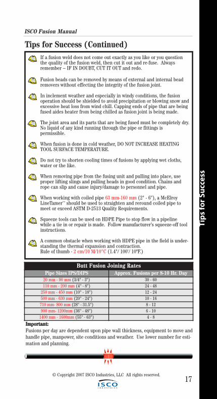
Butt Fusion Joining RatesPipe Sizes IPS/DIPS Approx. Fusions per 8-10 Hr. Day
20 mm - 90 mm (3/4" - 3") 30 - 60110 mm - 200 mm (4" - 8") 24 - 48
250 mm - 450 mm (10" - 18") 12 - 24500 mm - 630 mm (20" - 24") 10 - 16710 mm- 800 mm (28" - 31.5") 8 - 12900 mm- 1200mm (36" - 48") 6 - 10
1400 mm - 1600mm (55" - 63") 4 - 8
IImmppoorrttaanntt:: Fusions per day are dependent upon pipe wall thickness, equipment to move andhandle pipe, manpower, site conditions and weather. Use lower number for esti-mation and planning.
18
Manual Butt Fusion Machine Procedure
Man
ual B
utt Fu
sion
Mach
ine P
roced
ure
© Copyright 2007 ISCO Industries, LLC All rights reserved.
19
Man
ual
Bu
tt F
usi
on
Mac
hin
e P
roce
du
re
Manual Butt Fusion Machine ProcedureThe principle of heat fusion is to heat two surfaces to a designated temperature,and then fuse them together by application of force. This pressure causes flow ofthe melted materials, which causes mixing and thus fusion. When the polyethyl-ene material is heated, the molecular structure is transformed from a crystallinestate into an amorphous condition. When fusion pressure is applied, the mole-cules from each polyethylene part mix. As the joint cools, the molecules returnto their crystalline form, the original interfaces are gone, and the two pipesbecome one homogeneous unit.
The principle operations include:
Cleaning The pipe ends must be clean and free of any dirt, debris or other contaminants
Clamping The pipe pieces held axially to allow all subsequent operations to take place.
Facing The pipe ends must be faced to establish clean, parallel mating surfaces perpendicularto the centerline of the pipes.
Alignment The pipe ends must be aligned with each other to minimize mismatch or high-low of the pipe wall.
Heating A melt pattern that penetrates into the pipe must be formed around both pipe ends.
Joining The melt patterns must be joined with a specified force. The force must be constant around the interface area.
Holding The molten joint must be held immobile with a specified force until adequately cooled.
ISCO Fusion Manual
© Copyright 2007 ISCO Industries, LLC All rights reserved.
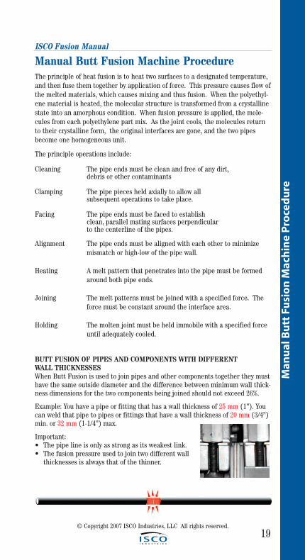
BUTT FUSION OF PIPES AND COMPONENTS WITH DIFFERENT WALL THICKNESSESWhen Butt Fusion is used to join pipes and other components together they musthave the same outside diameter and the difference between minimum wall thick-ness dimensions for the two components being joined should not exceed 26%.
Example: You have a pipe or fitting that has a wall thickness of 25 mm (1”). Youcan weld that pipe to pipes or fittings that have a wall thickness of 20 mm (3/4”)min. or 32 mm (1-1/4”) max.
Important:• The pipe line is only as strong as its weakest link.• The fusion pressure used to join two different wall
thicknesses is always that of the thinner.
ISCO Fusion Manual
20
Man
ual B
utt Fu
sion
Mach
ine P
roced
ure
© Copyright 2007 ISCO Industries, LLC All rights reserved.
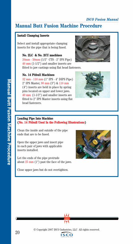
IInnssttaallll CCllaammppiinngg IInnsseerrttss
Select and install appropriate clampinginserts for the pipe that is being fused.
NNoo.. 22LLCC && NNoo.. 22CCUU mmaacchhiinneess20mm - 50mm (1/2" CTS - 2" IPS Pipe)40 mm (1-1/2") and smaller inserts are fitted to jaw castings using flat head fasteners.
NNoo.. 1144 PPiittbbuullll MMaacchhiinneess32 mm - 110 mm (1" IPS - 4" DIPS Pipe)2" IPS Master, 90 mm (3") & 110 mm(4") inserts are held in place by spring pins located on upper and lower jaws. 40 mm (1-1/2") and smaller inserts are fitted to 2" IPS Master inserts using flat head fasteners.
Manual Butt Fusion Machine Procedure
LLooaaddiinngg PPiippee IInnttoo MMaacchhiinnee ((NNoo.. 1144 PPiittbbuullll UUsseedd IInn tthhee FFoolllloowwiinngg IIlllluussttrraattiioonnss))
Clean the inside and outside of the pipeends that are to be fused.
Open the upper jaws and insert pipe in each pair of jaws with applicable inserts installed.
Let the ends of the pipe protrude about 25 mm (1") past the face of the jaws.
Close upper jaws but do not overtighten.
ISCO Fusion Manual
21
Man
ual
Bu
tt F
usi
on
Mac
hin
e P
roce
du
re
© Copyright 2007 ISCO Industries, LLC All rights reserved.
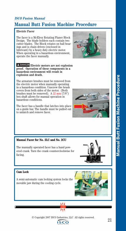
Electric Facer
The facer is a McElroy Rotating Planer BlockDesign. The blade holders each contain twocutter blades. The Block rotates on ball bear-ings and is chain driven (enclosed in lubricant) by a heavy duty electric motor.When operating in a hazardous environment,operate the facer manually.
Electric motors are not explosionproof. Operation of these components in a hazardous environment will result in explosion and death.
The armature brushes must be removed from the electric motor when manually operating in a hazardous condition. Unscrew the brush covers from both sides of the motor. (Bothbrushes must be removed). A 22 mm (7/8")hex shaft allows for manual operation in hazardous conditions.
The facer has a handle that latches into placeon a guide bar. The handle must be pulled outto unlatch and remove facer.
Manual Butt Fusion Machine Procedure
! DANGER
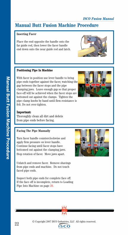
MMaannuuaall FFaacceerr ffoorr NNoo.. 22LLCC aanndd NNoo.. 22CCUU
The manually operated facer has a hand pow-ered crank. Turn the crank counterclockwise forfacing.
CCaamm LLoocckk
A semi-automatic cam locking system locks themovable jaw during the cooling cycle.
ISCO Fusion Manual
22© Copyright 2007 ISCO Industries, LLC All rights reserved.
Man
ual B
utt Fu
sion
Mach
ine P
roced
ure
Inserting Facer
Place the end opposite the handle onto the far guide rod, then lower the facer handle end down onto the near guide rod and latch.
PPoossiittiioonniinngg PPiippee IInn MMaacchhiinnee
With facer in position use lever handle to bringpipe ends together against the facer, watching the gap between the facer stops and the pipe clamping jaws. Leave enough gap so that properface-off will be achieved when the facer stops arebottomed out against the clamps. Tighten the pipe clamp knobs by hand until firm resistance is felt. Do not over-tighten.
IImmppoorrttaanntt::Thoroughly clean all dirt and debris from pipe ends before facing.
Manual Butt Fusion Machine Procedure
Facing The Pipe Manually
Turn facer handle counterclockwise and apply firm pressure on lever handle. Continue facing until facer stops havebottomed out against the clamping jaws. Stop rotation of facer. Move jaws apart.
Unlatch and remove facer. Remove shavings from pipe ends and machine. Do not touch faced pipe ends.
Inspect both pipe ends for complete face off. If the face off is incomplete, return to Loading Pipe Into Machine on page 20.

ISCO Fusion Manual
23
Man
ual
Bu
tt F
usi
on
Mac
hin
e P
roce
du
re
© Copyright 2007 ISCO Industries, LLC All rights reserved.
EElleeccttrriicc FFaacceerr
The electric facer should be startedbefore the pipe is pushed into contact with the blades.
Continue facing until the facer stops areagainst the jaws.
Turn off the facer while continuing to hold pressure closed on the lever until the facer stops completely.
Reverse force to the lever handle to move the pipe ends away from the facer.
Unlatch and remove the facer taking care not to touch the pipe ends.
Remove shavings from pipe ends and machine.
Do not touch faced pipe ends as this may contaminate them.
If faced pipe ends are touched, use a clean non-synthetic cloth to clean affected area before proceeding.
If after facing, any imperfections are visible, return to Loading Pipe Into Machine on page 20.
Any time clamp knobs are tightened, pipe ends should be refaced.
Manual Butt Fusion Machine Procedure
ISCO Fusion Manual
24© Copyright 2007 ISCO Industries, LLC All rights reserved.
Man
ual B
utt Fu
sion
Mach
ine P
roced
ure
Check Alignment Of Pipe
Bring the pipe ends together under suffi-cient force to overcome any pipe drag or fric-tion in the system.
Check for alignment and proper face off. Ifhigh/low (misalignment) exists, adjust bytightening the clamp on the high side andreface the pipes. Their should be no morethan 10% of the wall thickness in misalign-ment to maintain full joint strength.
Notice: When clamping, do not over-tighten the clamp knobs because machine damagecan result. Check to see if there is space between the upper and lower jaws. If the two jaws are touching, do not continue to tighten. Bring the pipe ends together under fusion pressure to check for slippage. If slippage occurs, return to Loading Pipe Into Machine section on page 20.
Manual Butt Fusion Machine Procedure
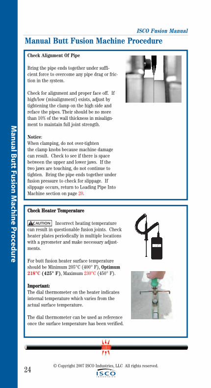
CChheecckk HHeeaatteerr TTeemmppeerraattuurree
Incorrect heating temperaturecan result in questionable fusion joints. Checkheater plates periodically in multiple locationswith a pyrometer and make necessary adjust-ments.
For butt fusion heater surface temperatureshould be Minimum 205°C (400° F), Optimum 218°C (425° F), Maximum 230°C (450° F).
IImmppoorrttaanntt::The dial thermometer on the heater indicatesinternal temperature which varies from theactual surface temperature.
The dial thermometer can be used as referenceonce the surface temperature has been verified.
CAUTION!
ISCO Fusion Manual
25
Man
ual
Bu
tt F
usi
on
Mac
hin
e P
roce
du
re
© Copyright 2007 ISCO Industries, LLC All rights reserved.
Inserting Heater
Heater Is Not Explosion Proof.Operation of heater in a hazardous environ-ment without necessary safety precautionswill result in explosion and death.
If operating in a hazardous environment, heatershould be brought up to temperature in a safeenvironment, then unplugged before entering the hazardous atmosphere for fusion.
Use a clean non-synthetic cloth to clean butt fusionheater adapter surfaces.
Check heater adapters for coating damage, plastic buildup rings and surfaceimperfections. These conditions could cause a poor fusion. Replace them ifconditions exist.
Verify heater temperature by referencing the reading on the dial thermometer.
Insert heater between the pipe ends. The stripper bar downward legs shouldbe outside of the jaws. (not on top)
Manual Butt Fusion Machine Procedure
! DANGER
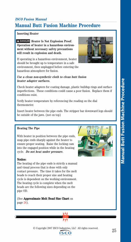
Heating The Pipe
With heater in position between the pipe ends,snap pipe ends sharply against the heater toensure proper seating. Raise the locking caminto the engaged position while in the heatingcycle. Do not heat under pressure.
NNoottiiccee:: The heating of the pipe ends is strictly a manualand visual process that is done with onlycontact pressure. The time it takes for the meltbeads to reach their proper size and heatingcycle is dependent on the working environment.The heating cycle is complete when the meltbeads are the following sizes depending on thepipe OD.
(See AApppprrooxxiimmaattee MMeelltt BBeeaadd SSiizzee CChhaarrtt onpage 26).
ISCO Fusion Manual
26© Copyright 2007 ISCO Industries, LLC All rights reserved.
Man
ual B
utt Fu
sion
Mach
ine P
roced
ure
Approximate Melt Bead Size (Pipe Ends):
Pipe Size Approximate Melt Bead
40 mm (1-1/4") and smaller 1mm - 2 mm (1/32" – 1/16")
50 mm (1-1/2") through 90 mm (3") 2 mm - 3 mm (1/16" – 1/8")
110 mm (4") 3 mm - 5 mm (1/8" – 3/16")
Manual Butt Fusion Machine Procedure
Fusing the Pipe
Once melt beads are of proper size, remove the heater, QUICKLY inspect the melted ends, which should be flat, smooth, and completely melted. If the melted surfaces are acceptable, immediately and in a continuous motion, bring the ends together and apply enough joining force for the beads to touch, flare up and roll back till they come in FULL contact with the pipe surfaces being fused. Do not slam.
A concave melt surface is unacceptable; it indicates pressure during heat-ing. Do not continue. Allow the melted ends to cool and start over.
The locking cams will assist by holding force during the cooling cycle.
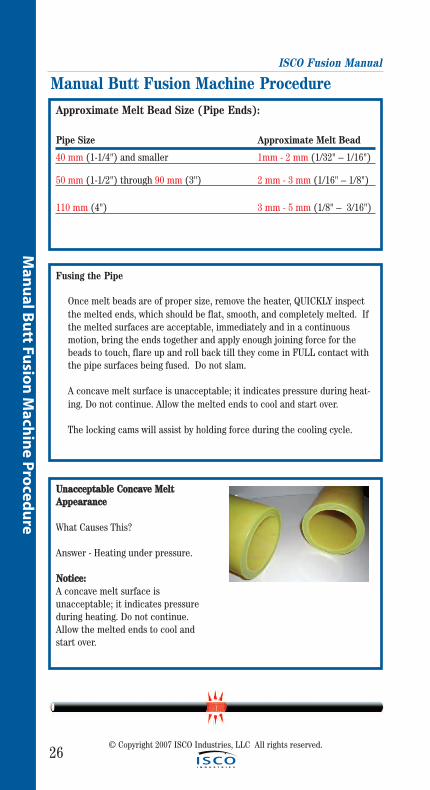
UUnnaacccceeppttaabbllee CCoonnccaavvee MMeellttAAppppeeaarraannccee
What Causes This?
Answer - Heating under pressure.
NNoottiiccee::A concave melt surface is unacceptable; it indicates pressure during heating. Do not continue. Allow the melted ends to cool andstart over.
ISCO Fusion Manual
27
Man
ual
Bu
tt F
usi
on
Mac
hin
e P
roce
du
re
© Copyright 2007 ISCO Industries, LLC All rights reserved.
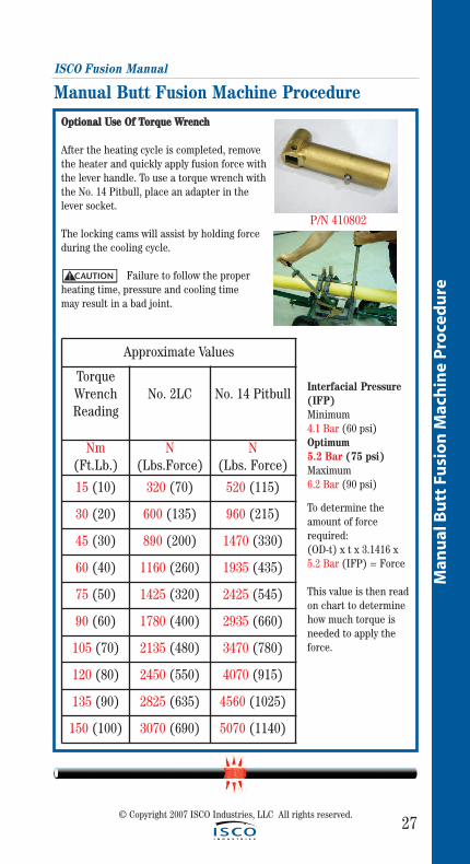
Manual Butt Fusion Machine ProcedureOOppttiioonnaall UUssee OOff TToorrqquuee WWrreenncchh
After the heating cycle is completed, removethe heater and quickly apply fusion force withthe lever handle. To use a torque wrench withthe No. 14 Pitbull, place an adapter in the lever socket.
The locking cams will assist by holding forceduring the cooling cycle.
Failure to follow the proper heating time, pressure and cooling time may result in a bad joint.
Approximate Values
TorqueWrenchReading
No. 2LC No. 14 Pitbull
Nm(Ft.Lb.)
N(Lbs.Force)
N(Lbs. Force)
15 (10) 320 (70) 520 (115)
30 (20) 600 (135) 960 (215)
45 (30) 890 (200) 1470 (330)
60 (40) 1160 (260) 1935 (435)
75 (50) 1425 (320) 2425 (545)
90 (60) 1780 (400) 2935 (660)
105 (70) 2135 (480) 3470 (780)
120 (80) 2450 (550) 4070 (915)
135 (90) 2825 (635) 4560 (1025)
150 (100) 3070 (690) 5070 (1140)
CAUTION!
Interfacial Pressure(IFP)Minimum 4.1 Bar (60 psi)Optimum 5.2 Bar (75 psi) Maximum 6.2 Bar (90 psi)
To determine the amount of forcerequired: (OD-t) x t x 3.1416 x5.2 Bar (IFP) = Force
This value is then readon chart to determinehow much torque isneeded to apply theforce.
P/N 410802
ISCO Fusion Manual
28
Man
ual B
utt Fu
sion
Mach
ine P
roced
ure
© Copyright 2007 ISCO Industries, LLC All rights reserved.
Cooling Of The Fusion Joint
The fusion joint must be keptunder pressure until the joint iscool. This time will vary with pipesize, wall thickness, heater tem-perature setting and environmen-tal conditions.
There are three acceptable meth-ods that can be used individuallyor combined.
1) Cool to the touch.
2) Timing "Guidelines Only" Chart.
3) Use pyrometer to measure temperature of the weld bead and compare it to the temperature of the pipe and or fittings being fused. If the tem-peratures are the same, the cooling requirement has been met.
NNoottiiccee:: Heavier wall thickness pipes require longer cooling times.
Allow the joint to cool an additional thirty (30) minutes minimum outside of the fusion machine before subjecting the fusion joint to any rough han-dling or severe bending.
Manual Butt Fusion Machine Procedure
Wall Thickness ofPipe being Fused
Cooling Time 23°C
(74 º F)
Up to 5 mm (0.2") 5 min.
5 mm (0.2") to 10 mm (0.4")
5 to 10 min.
10 mm (0.4") to15 mm (0.6")
10 to 15 min.
15mm (0.6") to 20 mm (0.8")
15 to 20 min.
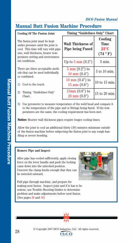
Remove Pipe and Inspect
After pipe has cooled sufficiently, apply closingforce on the lever handle and push the lockingcams down into the unlocked position. Unscrew the clamp knobs enough that they can be swiveled outward.
Pull pipe through machine, and prepare formaking next fusion. Inspect joint and if it has to be redone, use Trouble Shooting Guides to determine problem and make adjustments before next fusion.(See pages 29 and 30)
Timing “Guidelines Only” Chart
29
Man
ual
Bu
tt F
usi
on
Mac
hin
e P
roce
du
re
ISCO Fusion Manual
Manual Butt Fusion Machine Procedure
© Copyright 2007 ISCO Industries, LLC All rights reserved.
The Inspection Of The Fusion Joint
Golden Rule: If in doubt, cut it out and redo.
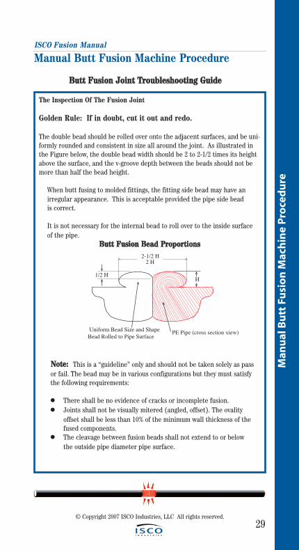
The double bead should be rolled over onto the adjacent surfaces, and be uni-formly rounded and consistent in size all around the joint. As illustrated inthe Figure below, the double bead width should be 2 to 2-1/2 times its heightabove the surface, and the v-groove depth between the beads should not bemore than half the bead height.
When butt fusing to molded fittings, the fitting side bead may have an irregular appearance. This is acceptable provided the pipe side bead is correct.
It is not necessary for the internal bead to roll over to the inside surface of the pipe.
BBuutttt FFuussiioonn BBeeaadd PPrrooppoorrttiioonnss
NNoottee:: This is a “guideline” only and should not be taken solely as passor fail. The bead may be in various configurations but they must satisfythe following requirements:
● There shall be no evidence of cracks or incomplete fusion.● Joints shall not be visually mitered (angled, offset). The ovality
offset shall be less than 10% of the minimum wall thickness of the fused components.
● The cleavage between fusion beads shall not extend to or below the outside pipe diameter pipe surface.
H
2-1/2 H2 H
1/2 H
Uniform Bead Size and ShapeBead Rolled to Pipe Surface PE Pipe (cross section view).
BBuutttt FFuussiioonn JJooiinntt TTrroouubblleesshhoooottiinngg GGuuiiddee
ISCO Fusion Manual
30
Man
ual B
utt Fu
sion
Mach
ine P
roced
ure
© Copyright 2007 ISCO Industries, LLC All rights reserved.
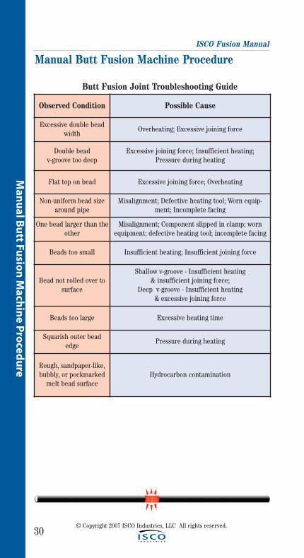
Manual Butt Fusion Machine Procedure
Observed Condition Possible Cause
Excessive double beadwidth
Overheating; Excessive joining force
Double bead v-groove too deep
Excessive joining force; Insufficient heating; Pressure during heating
Flat top on bead Excessive joining force; Overheating
Non-uniform bead sizearound pipe
Misalignment; Defective heating tool; Worn equip-ment; Incomplete facing
One bead larger than theother
Misalignment; Component slipped in clamp; wornequipment; defective heating tool; incomplete facing
Beads too small Insufficient heating; Insufficient joining force
Bead not rolled over tosurface
Shallow v-groove - Insufficient heating & insufficient joining force;
Deep v-groove - Insufficient heating & excessive joining force
Beads too large Excessive heating time
Squarish outer beadedge
Pressure during heating
Rough, sandpaper-like,bubbly, or pockmarked
melt bead surfaceHydrocarbon contamination
Butt Fusion Joint Troubleshooting Guide
31
Hyd
rau
lic B
utt
Fu
sio
n M
ach
ine
Pro
ced
ure
© Copyright 2007 ISCO Industries, LLC All rights reserved.
Hydraulic Butt Fusion Machine Procedure
ISCO Fusion Manual
32
Hyd
raulic B
utt Fu
sion
Mach
ine P
roced
ure
© Copyright 2007 ISCO Industries, LLC All rights reserved.
Hydraulic Butt Fusion Machine ProcedureThe principle of heat fusion is to heat two surfaces to a designated temperature,and then fuse them together by application of force. This pressure causes flow ofthe melted materials, which causes mixing and thus fusion. When the polyethyl-ene material is heated, the molecular structure is transformed from a crystallinestate into an amorphous condition. When fusion pressure is applied, the mole-cules from each polyethylene part mix. As the joint cools, the molecules returnto their crystalline form, the original interfaces are gone, and the two pipes havebecome one homogeneous unit.
The principle operations include:
Cleaning The pipe ends must be clean and free of any dirt, debris or other contaminants
Clamping The pipe pieces held axially to allow all subsequent operations to take place.
Facing The pipe ends must be faced to establish clean, parallel mating surfaces perpendicularto the centerline of the pipes.
Alignment The pipe ends must be aligned with each other to minimize mismatch or high-low of the pipe wall.
Heating A melt pattern that penetrates into the pipe must be formed around both pipe ends.
Joining The melt patterns must be joined with a specified force. The force must be constant around the interface area.
Holding The molten joint must be held immobile with a specified force until adequately cooled.
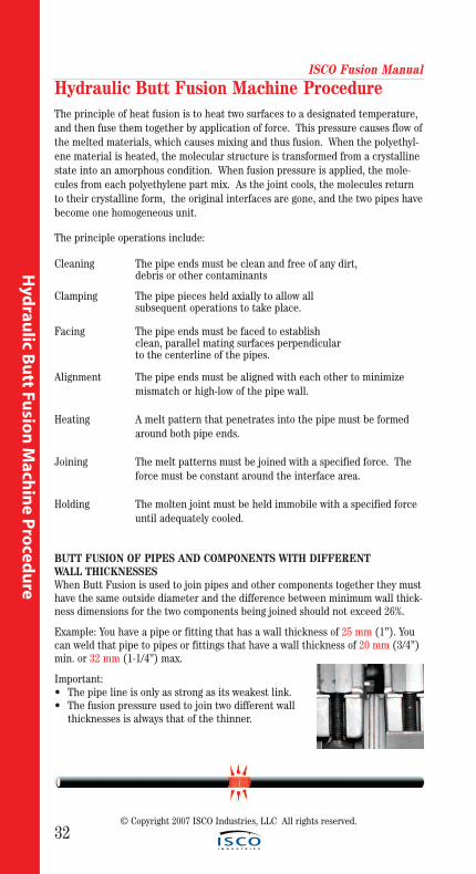
BUTT FUSION OF PIPES AND COMPONENTS WITH DIFFERENT WALL THICKNESSESWhen Butt Fusion is used to join pipes and other components together they musthave the same outside diameter and the difference between minimum wall thick-ness dimensions for the two components being joined should not exceed 26%.
Example: You have a pipe or fitting that has a wall thickness of 25 mm (1”). Youcan weld that pipe to pipes or fittings that have a wall thickness of 20 mm (3/4”)min. or 32 mm (1-1/4”) max.
Important:• The pipe line is only as strong as its weakest link.• The fusion pressure used to join two different wall
thicknesses is always that of the thinner.

ISCO Fusion Manual
33
Hyd
rau
lic B
utt
Fu
sio
n M
ach
ine
Pro
ced
ure
Hydraulic Butt Fusion Machine Procedure
Hydraulic Manifold Block
Mounted on this block are a carriage directionalcontrol valve, a selector valve, three pressurereducing valves, and a pressure gauge.
A) The carriage control value, mounted on the top of the manifold, determines whether the carriage is moving left, right, or in neutral.
B) A pressure gauge is mounted on top of themanifold.
C) The selector valve, mounted on the front ofthe manifold, selects a pressure from one of thepressure reducing valves. Each pressure reduc-ing valve is labeled with a different function.
D) The top valve adjusts facing pressure, normally 3 to 7 Bar (50-100 psi) gauge pressure.
E) The middle valve adjusts heating pressure,always 0 Bar (0 psi) or backed all the way outturning knob counterclockwise. The drag pres-sure may have to be compensated for when working with more than one joint of pipe on the movable sideor with tie-ins.
F) The bottom valve adjusts fusion pressure, this pressuremust be determined.
FACING
HEATING
FUSING
B C A
DEF
Install Clamping Inserts
Select and install appropriate clamping inserts for the pipe that is being fused.
© Copyright 2007 ISCO Industries, LLC All rights reserved.
ISCO Fusion Manual
34
Hyd
raulic B
utt Fu
sion
Mach
ine P
roced
ure
© Copyright 2007 ISCO Industries, LLC All rights reserved.
Hydraulic Butt Fusion Machine Procedure
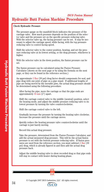
Check Hydraulic Pressure
The pressure gauge on the manifold block indicates the pressure of the carriage valve. How much pressure depends on the position of the selec-tor valve and the pressure set on the specific pressure reducing valve. With the selector valve up, the facing pressure can be set. It may be nec-essary to adjust the carriage speed, while facing, with the top pressure- reducing valve to control facing speed.
Shift the selector valve to the center position, heating, and set the pres-sure reducing valve at its lowest setting, or the drag pressure, whichever is higher.
With the selector valve in the down position, the fusion pressure can be set.
The fusion pressure can be calculated using the Fusion Pressure Calculator (shown on the next page or by using the formula on the next page, or they can be found in the reference section.)
An approximate 2 Bar (30 psi) drag factor should compensate for seal, andpipe drag with one joint of pipe on a pipe stand. If additional lengths of pipe are being moved by the movable jaws, the actual drag pressure shouldbe determined using the following procedure:
After facing the pipe, move the carriage so that the pipe ends are approximately 50 mm (2") apart.
Shift the carriage control valve to the middle (neutral) position, select the heating mode, and adjust the middle pressure reducing valve to its lowest pressure by turning the valve counterclockwise.
Shift the carriage control valve to the left.
Gradually increase the pressure by turning the heating valve clockwise. Increase the pressure until the carriage moves.
Quickly reduce the heating pressure valve counterclockwise until the carriage is just barely moving.
Record this actual drag pressure.
Take the pressure, determined from the Fusion Pressure Calculator, andadd the actual measured drag pressure. This will be the actual fusion pressure to set with the bottom pressure reducing valve. If fusion pres-sures are used from the reference section, you must subtract 2 Bar (30 psi) drag, which is already figured in and then add the actual drag pressure back.
Adjust the middle heating valve to show recorded drag so that pipe endswill stay in contact with heater during heating phase.
ISCO Fusion Manual
35
Hyd
rau
lic B
utt
Fu
sio
n M
ach
ine
Pro
ced
ure
Hydraulic Butt Fusion Machine Procedure
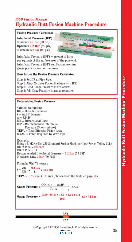
Fusion Pressure Calculator
Interfacial Pressure (IFP)Minimum 4.1 Bar (60 psi)Optimum 5.2 Bar (75 psi) Maximum 6.2 Bar (90 psi)
Interfacial Pressure (IFP) = amount of force per sq. inch of the surface area of the pipe end. Interfacial Pressure (IFP) and Fusion machine gauge pressure are not the same.
HHooww ttoo UUssee tthhee FFuussiioonn PPrreessssuurree CCaallccuullaattoorr
Step 1: Set DR at Pipe Size.Step 2: Align McElroy Fusion Machine with IFP.Step 3: Read Gauge Pressure at red arrow.Step 4: Add Drag Pressure to gauge pressure.
Determining Fusion Pressure
Variable DefinitionsOD = Outside Diametert = Wall Thicknessπ = 3.1416DR = Dimensional RatioIFP =Recommended Interfacial
Pressure (Shown Above)TEPA = Total Effective Piston AreaDRAG = Force Required to Move Pipe
Example:Using a McElroy No. 250 Standard Fusion Machine (Low Force, Yellow Cyl.)OD of Pipe = 200 mmDR of Pipe = 11Recommended Interfacial Pressure = 5.2 Bar (75 PSI)Measured Drag 2 Bar (30 PSI)
Formula: Wall Thickness
t =
TEPA = 1077 mm2 (1.67 in2) (chosen from the table on page 36)
Gauge Pressure =
Gauge Pressure = (200 - 18.2) x 18.2 x 3.14 x 5.2
1077+2 = 52 Bar
(OD - t) x t x π x IFP
TEP A= DRAG
ODDR
=11
200 mm = 18.2 mm
+
© Copyright 2007 ISCO Industries, LLC All rights reserved.
ISCO Fusion Manual
36
Hyd
raulic B
utt Fu
sion
Mach
ine P
roced
ure
© Copyright 2007 ISCO Industries, LLC All rights reserved.
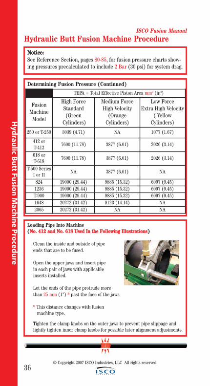
Loading Pipe Into Machine((NNoo.. 441122 aanndd NNoo.. 661188 UUsseedd IInn tthhee FFoolllloowwiinngg IIlllluussttrraattiioonnss))
Clean the inside and outside of pipe ends that are to be fused.
Open the upper jaws and insert pipe in each pair of jaws with applicable inserts installed.
Let the ends of the pipe protrude more than 25 mm (1") * past the face of the jaws.
* This distance changes with fusionmachine type.
Tighten the clamp knobs on the outer jaws to prevent pipe slippage and lightly tighten inner clamp knobs for possible later alignment adjustments.
Determining Fusion Pressure (Continued)
Hydraulic Butt Fusion Machine Procedure
TEPA = Total Effective Piston Area mm2 (in2)
FusionMachine
Model
High ForceStandard(Green
Cylinders)
Medium ForceHigh Velocity
(OrangeCylinders)
Low ForceExtra High Velocity
( Yellow Cylinders)
250 or T-250 3039 (4.71) NA 1077 (1.67)
412 or T-412
7600 (11.78) 3877 (6.01) 2026 (3.14)
618 or T-618
7600 (11.78) 3877 (6.01) 2026 (3.14)
T-500 SeriesI or II
NA 3877 (6.01) NA
824 19000 (29.44) 9885 (15.32) 6097 (9.45)1236 19000 (29.44) 9885 (15.32) 6097 (9.45)T-900 19000 (29.44) 9885 (15.32) 6097 (9.45)1648 20272 (31.42) 9123 (14.14) NA2065 20272 (31.42) NA NA
NNoottiiccee::See Reference Section, pages 80-85, for fusion pressure charts show-ing pressures precalculated to include 2 Bar (30 psi) for system drag.
ISCO Fusion Manual
37
Hyd
rau
lic B
utt
Fu
sio
n M
ach
ine
Pro
ced
ure
Hydraulic Butt Fusion Machine Procedure
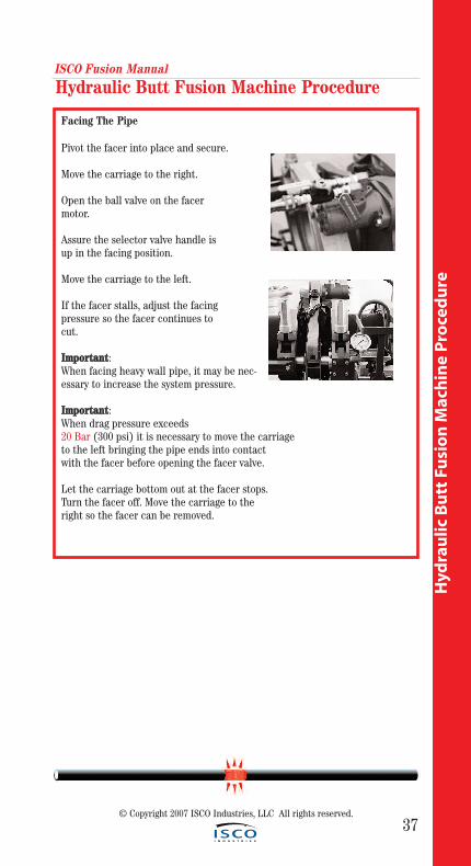
Facing The Pipe
Pivot the facer into place and secure.
Move the carriage to the right.
Open the ball valve on the facer motor.
Assure the selector valve handle is up in the facing position.
Move the carriage to the left.
If the facer stalls, adjust the facing pressure so the facer continues to cut.
IImmppoorrttaanntt: When facing heavy wall pipe, it may be nec-essary to increase the system pressure.
IImmppoorrttaanntt: When drag pressure exceeds20 Bar (300 psi) it is necessary to move the carriageto the left bringing the pipe ends into contact with the facer before opening the facer valve.
Let the carriage bottom out at the facer stops. Turn the facer off. Move the carriage to the right so the facer can be removed.
© Copyright 2007 ISCO Industries, LLC All rights reserved.
ISCO Fusion Manual
38
Hyd
raulic B
utt Fu
sion
Mach
ine P
roced
ure
© Copyright 2007 ISCO Industries, LLC All rights reserved.
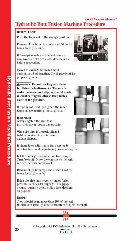
Remove Facer
Pivot the facer out to the storage position.
Remove chips from pipe ends, careful not totouch faced pipe ends.
If faced pipe ends are touched, use cleannon-synthetic cloth to clean affected area before proceeding.
Move the carriage to the left untilends of pipe butt together. Check pipe joint for proper alignment.
Do not use finger to check for hi/low (misalignment). The unit isunder pressure, and slippage could resultin crushed fingers. Always keep hands clear of the jaw area.
If pipe is not lined up, tighten the inner high side jaw to bring into alignment.
Important:Always tighten the side that is higher, never loosen the low side.
When the pipe is properly aligned tighten outside clamps to insure against slippage.
If clamp knob adjustment has been made,reinstall facer and begin facing procedure again.
Let the carriage bottom out on facer stops. Turn facer off. Move the carriage to the rightso the facer can be removed.
Remove chips from pipe ends careful not to touch faced pipe ends.
Bring the pipe ends together under fusion pressure to check for slippage. If slippageoccurs, return to Loading Pipe Into Machine on page 36.
NNoottiiccee::Their should be no more than 10% of the wall thickness in misalignment to maintain full joint strength.
Hydraulic Butt Fusion Machine Procedure
WARNING!
ISCO Fusion Manual
39
Hyd
rau
lic B
utt
Fu
sio
n M
ach
ine
Pro
ced
ureCChheecckk HHeeaatteerr TTeemmppeerraattuurree
Incorrect heating temperaturecan result in questionable fusion joints. Checkheater plates periodically in multiple locationswith a pyrometer and make necessary adjustments.
For butt fusion heater surface temperatureshould be Minimum 205°C (400° F), Optimum218°C (425° F), Maximum 230°C (450° F).
IImmppoorrttaanntt:: The dial thermometer on the heater indicates internal temperature. The dial thermometer can be used as reference once the surface temperature hasbeen verified.
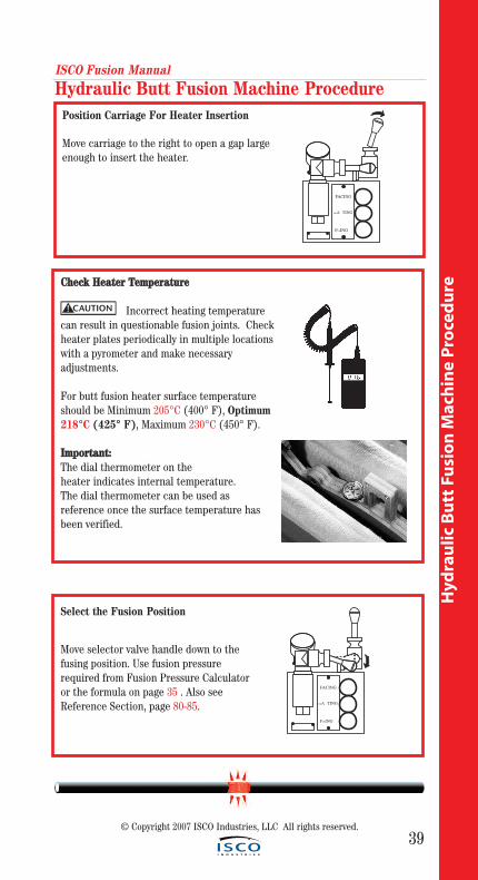
Position Carriage For Heater Insertion
Move carriage to the right to open a gap largeenough to insert the heater.
Hydraulic Butt Fusion Machine Procedure
CAUTION!
FACING
HEA TING
FUSING
Select the Fusion Position
Move selector valve handle down to thefusing position. Use fusion pressurerequired from Fusion Pressure Calculatoror the formula on page 35 . Also seeReference Section, page 80-85.
FACING
HEA TING
FUSING
© Copyright 2007 ISCO Industries, LLC All rights reserved.
ISCO Fusion Manual
40
Hyd
raulic B
utt Fu
sion
Mach
ine P
roced
ure
© Copyright 2007 ISCO Industries, LLC All rights reserved.
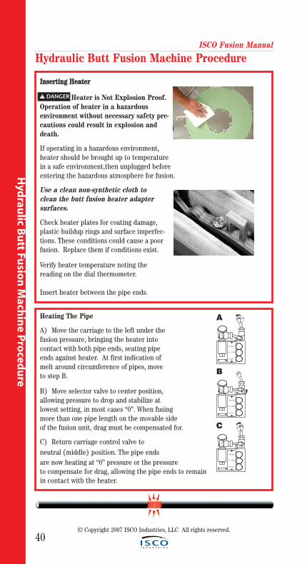
Heating The Pipe
A) Move the carriage to the left under the fusion pressure, bringing the heater into contact with both pipe ends, seating pipe ends against heater. At first indication of melt around circumference of pipes, move to step B.
B) Move selector valve to center position, allowing pressure to drop and stabilize at lowest setting, in most cases “0”. When fusingmore than one pipe length on the movable sideof the fusion unit, drag must be compensated for.
C) Return carriage control valve to neutral (middle) position. The pipe ends are now heating at “0” pressure or the pressure to compensate for drag, allowing the pipe ends to remain in contact with the heater.
IInnsseerrttiinngg HHeeaatteerr
Heater is Not Explosion Proof.Operation of heater in a hazardous environment without necessary safety pre-cautions could result in explosion anddeath.
If operating in a hazardous environment, heater should be brought up to temperature in a safe environment,then unplugged before entering the hazardous atmosphere for fusion.
Use a clean non-synthetic cloth to clean the butt fusion heater adapter surfaces.
Check heater plates for coating damage, plastic buildup rings and surface imperfec-tions. These conditions could cause a poorfusion. Replace them if conditions exist.
Verify heater temperature noting the reading on the dial thermometer.
Insert heater between the pipe ends.
Hydraulic Butt Fusion Machine Procedure
! DANGER
FACING
HEA TING
FUSING
A
FACING
HEA TING
FUSING
B
FACING
HEA TING
FUSING
C
Hyd
rau
lic B
utt
Fu
sio
n M
ach
ine
Pro
ced
ure
ISCO Fusion Manual
41
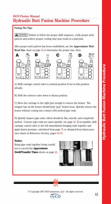
Fusing The Pipe
Failure to follow the proper shift sequence, verify proper meltpattern and achieve proper cooling time may result in a bad joint.
After proper melt pattern has been established, use the Approximate MeltBead Size chart on page 42 to determine the proper size, then:
A) Shift carriage control valve to neutral position if not in this positionalready.
B) Shift the selector valve down to fusion position.
C) Move the carriage to the right just enough to remove the heater. Thestripper bar on the heater should help “pop” heater loose. Quickly remove theheater without coming into contact with melted pipe ends.
D) Quickly inspect pipe ends, which should be flat, smooth, and completelymelted. Concave pipe ends are unacceptable, see page 42. If acceptable, shiftcarriage control valve to the left immediately bringing ends together andapply fusion pressure, calculated from page 35 or obtained from fusion pres-sure charts in Reference Section, pages 80-85.
NNoottiiccee:: Bring pipe ends together being carefulnot to exceed the AApppprrooxxiimmaatteeDDwweellll//TTrraannssffeerr TTiimmeess shown on page 42.
Hydraulic Butt Fusion Machine Procedure
CAUTION!
FACING
HEA TING
FUSING
A
FACING
HEA TING
FUSING
D
FACING
HEA TING
FUSING
C
FACING
HEA TING
FUSING
B
© Copyright 2007 ISCO Industries, LLC All rights reserved.
ISCO Fusion Manual
42
Hyd
raulic B
utt Fu
sion
Mach
ine P
roced
ure
© Copyright 2007 ISCO Industries, LLC All rights reserved.
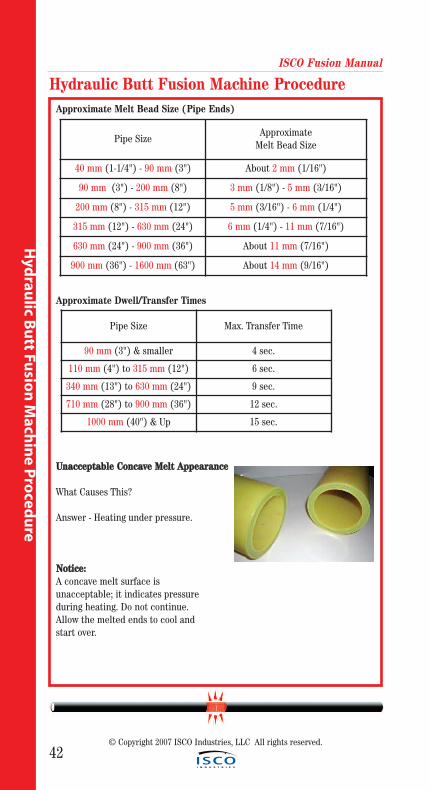
Approximate Melt Bead Size (Pipe Ends)
Approximate Dwell/Transfer Times
UUnnaacccceeppttaabbllee CCoonnccaavvee MMeelltt AAppppeeaarraannccee
What Causes This?
Answer - Heating under pressure.
NNoottiiccee::A concave melt surface is unacceptable; it indicates pressure during heating. Do not continue. Allow the melted ends to cool andstart over.
Hydraulic Butt Fusion Machine Procedure
Pipe SizeApproximate
Melt Bead Size
40 mm (1-1/4") - 90 mm (3") About 2 mm (1/16")
90 mm (3") - 200 mm (8") 3 mm (1/8") - 5 mm (3/16")
200 mm (8") - 315 mm (12") 5 mm (3/16") - 6 mm (1/4")
315 mm (12") - 630 mm (24") 6 mm (1/4") - 11 mm (7/16")
630 mm (24") - 900 mm (36") About 11 mm (7/16")
900 mm (36") - 1600 mm (63") About 14 mm (9/16")
Pipe Size Max. Transfer Time
90 mm (3") & smaller 4 sec.
110 mm (4") to 315 mm (12") 6 sec.
340 mm (13") to 630 mm (24") 9 sec.
710 mm (28") to 900 mm (36") 12 sec.
1000 mm (40") & Up 15 sec.
43
ISCO Fusion Manual
Hyd
rau
lic B
utt
Fu
sio
n M
ach
ine
Pro
ced
ure
Hydraulic Butt Fusion Machine Procedure
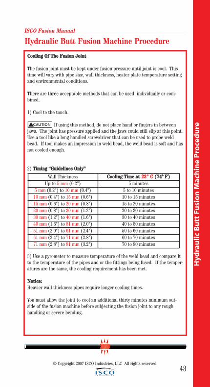
CCoooolliinngg OOff TThhee FFuussiioonn JJooiinntt
The fusion joint must be kept under fusion pressure until joint is cool. Thistime will vary with pipe size, wall thickness, heater plate temperature settingand environmental conditions.
There are three acceptable methods that can be used individually or com-bined.
1) Cool to the touch.
If using this method, do not place hand or fingers in betweenjaws. The joint has pressure applied and the jaws could still slip at this point.Use a tool like a long handled screwdriver that can be used to probe weldbead. If tool makes an impression in weld bead, the weld bead is soft and hasnot cooled enough.
2) TTiimmiinngg ““GGuuiiddeelliinneess OOnnllyy””
3) Use a pyrometer to measure temperature of the weld bead and compare itto the temperature of the pipes and or the fittings being fused. If the temper-atures are the same, the cooling requirement has been met.
NNoottiiccee:: Heavier wall thickness pipes require longer cooling times.
You must allow the joint to cool an additional thirty minutes minimum out-side of the fusion machine before subjecting the fusion joint to any rough handling or severe bending.
Wall Thickness CCoooolliinngg TTiimmee aatt 2233°° CC ((7744ºº FF))Up to 5 mm (0.2") 5 minutes
5 mm (0.2") to 10 mm (0.4") 5 to 10 minutes10 mm (0.4") to 15 mm (0.6") 10 to 15 minutes15 mm (0.6") to 20 mm (0.8") 15 to 20 minutes20 mm (0.8") to 30 mm (1.2") 20 to 30 minutes30 mm (1.2") to 40 mm (1.6") 30 to 40 minutes40 mm (1.6") to 51 mm (2.0") 40 to 50 minutes51 mm (2.0") to 61 mm (2.4") 50 to 60 minutes61 mm (2.4") to 71 mm (2.8") 60 to 70 minutes71 mm (2.8") to 81 mm (3.2") 70 to 80 minutes
CAUTION!
© Copyright 2007 ISCO Industries, LLC All rights reserved.
ISCO Fusion Manual
44
Hyd
raulic B
utt Fu
sion
Mach
ine P
roced
ure
© Copyright 2007 ISCO Industries, LLC All rights reserved.
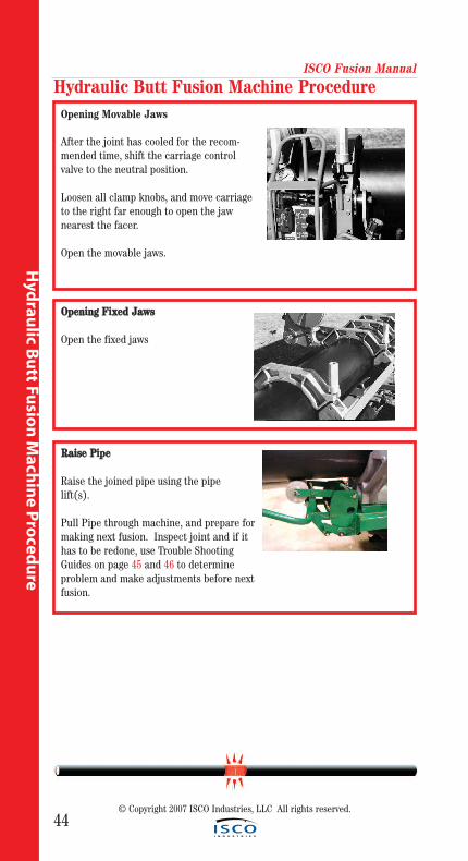
Opening Movable Jaws
After the joint has cooled for the recom-mended time, shift the carriage controlvalve to the neutral position.
Loosen all clamp knobs, and move carriage to the right far enough to open the jaw nearest the facer.
Open the movable jaws.
Hydraulic Butt Fusion Machine Procedure
OOppeenniinngg FFiixxeedd JJaawwss
Open the fixed jaws
RRaaiissee PPiippee
Raise the joined pipe using the pipe lift(s).
Pull Pipe through machine, and prepare formaking next fusion. Inspect joint and if ithas to be redone, use Trouble ShootingGuides on page 45 and 46 to determine problem and make adjustments before nextfusion.
ISCO Fusion Manual
45
Hyd
rau
lic B
utt
Fu
sio
n M
ach
ine
Pro
ced
ure
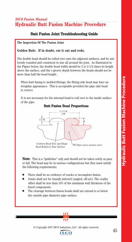
The Inspection Of The Fusion Joint
Golden Rule: If in doubt, cut it out and redo.
The double bead should be rolled over onto the adjacent surfaces, and be uni-formly rounded and consistent in size all around the joint. As illustrated inthe Figure below, the double bead width should be 2 to 2-1/2 times its heightabove the surface, and the v-groove depth between the beads should not bemore than half the bead height.
When butt fusing to molded fittings, the fitting side bead may have an irregular appearance. This is acceptable provided the pipe side bead is correct.
It is not necessary for the internal bead to roll over to the inside surface of the pipe.
BBuutttt FFuussiioonn BBeeaadd PPrrooppoorrttiioonnss
NNoottee:: This is a “guideline” only and should not be taken solely as passor fail. The bead may be in various configurations but they must satisfythe following requirements:
● There shall be no evidence of cracks or incomplete fusion.● Joints shall not be visually mitered (angled, off-set). The ovality
offset shall be less than 10% of the minimum wall thickness of the fused components.
● The cleavage between fusion beads shall not extend to or below the outside pipe diameter pipe surface.
Hydraulic Butt Fusion Machine Procedure
H
2-1/2 H2 H
1/2 H
Uniform Bead Size and ShapeBead Rolled to Pipe Surface PE Pipe (cross section view).
© Copyright 2007 ISCO Industries, LLC All rights reserved.
BBuutttt FFuussiioonn JJooiinntt TTrroouubblleesshhoooottiinngg GGuuiiddee
46
ISCO Fusion Manual
Hyd
raulic B
utt Fu
sion
Mach
ine P
roced
ure
© Copyright 2007 ISCO Industries, LLC All rights reserved.
Hydraulic Butt Fusion Machine Procedure
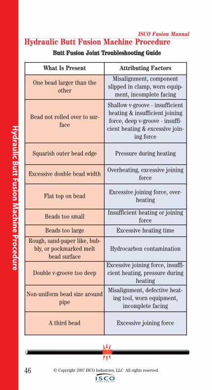
What Is Present Attributing Factors
One bead larger than theother
Misalignment, componentslipped in clamp, worn equip-
ment, incomplete facing
Bead not rolled over to sur-face
Shallow v-groove - insufficientheating & insufficient joiningforce, deep v-groove - insuffi-
cient heating & excessive join-ing force
Squarish outer bead edge Pressure during heating
Excessive double bead widthOverheating, excessive joining
force
Flat top on beadExcessive joining force, over-
heating
Beads too smallInsufficient heating or joining
force
Beads too large Excessive heating time
Rough, sand-paper like, bub-bly, or pockmarked melt
bead surfaceHydrocarbon contamination
Double v-groove too deepExcessive joining force, insuffi-cient heating, pressure during
heating
Non-uniform bead size aroundpipe
Misalignment, defective heat-ing tool, worn equipment,
incomplete facing
A third bead Excessive joining force
BBuutttt FFuussiioonn JJooiinntt TTrroouubblleesshhoooottiinngg GGuuiiddee
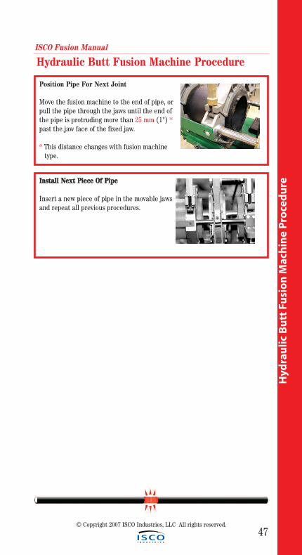
Position Pipe For Next Joint
Move the fusion machine to the end of pipe, orpull the pipe through the jaws until the end ofthe pipe is protruding more than 25 mm (1") *past the jaw face of the fixed jaw.
* This distance changes with fusion machinetype.
IInnssttaallll NNeexxtt PPiieeccee OOff PPiippee
Insert a new piece of pipe in the movable jawsand repeat all previous procedures.
ISCO Fusion Manual
47
Hyd
rau
lic B
utt
Fu
sio
n M
ach
ine
Pro
ced
ure
Hydraulic Butt Fusion Machine Procedure
© Copyright 2007 ISCO Industries, LLC All rights reserved.
48
Sadd
le Fusio
n M
achin
e Pro
cedu
re
Saddle Fusion Machine Procedure
© Copyright 2007 ISCO Industries, LLC All rights reserved.
ISCO Fusion Manual
49
Sad
dle
Fu
sio
n M
ach
ine
Pro
ced
ure
© Copyright 2007 ISCO Industries, LLC All rights reserved.
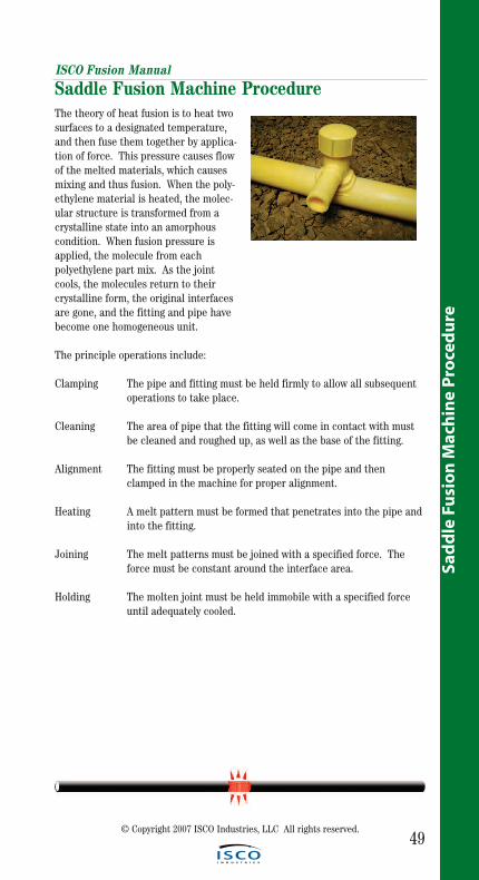
The theory of heat fusion is to heat twosurfaces to a designated temperature,and then fuse them together by applica-tion of force. This pressure causes flowof the melted materials, which causesmixing and thus fusion. When the poly-ethylene material is heated, the molec-ular structure is transformed from acrystalline state into an amorphouscondition. When fusion pressure isapplied, the molecule from each polyethylene part mix. As the jointcools, the molecules return to their crystalline form, the original interfaces are gone, and the fitting and pipe have become one homogeneous unit.
The principle operations include:
Clamping The pipe and fitting must be held firmly to allow all subsequent operations to take place.
Cleaning The area of pipe that the fitting will come in contact with must be cleaned and roughed up, as well as the base of the fitting.
Alignment The fitting must be properly seated on the pipe and then clamped in the machine for proper alignment.
Heating A melt pattern must be formed that penetrates into the pipe and into the fitting.
Joining The melt patterns must be joined with a specified force. The force must be constant around the interface area.
Holding The molten joint must be held immobile with a specified force until adequately cooled.
Saddle Fusion Machine Procedure
ISCO Fusion Manual
50
Sadd
le Fusio
n M
achin
e Pro
cedu
re
© Copyright 2007 ISCO Industries, LLC All rights reserved.
Saddle Fusion Procedures
Initial Heat (Bead-up): The heating step used to develop a melt bead on themain pipe.
Initial Heat Force (Bead-up force): The force applied to establish a melt pat-tern on the main pipe. The Initial Heat Force is determined by multiplying thefitting base area by the initial heat interfacial pressure (Bar per 25.4 mm2). Thisforce is twice the fusion force.
Heat Soak Force: The force applied after an initial melt pattern is establishedon the main pipe. The Heat Soak Force is the minimum force (essentially zeroBar) that ensures that the fitting, heater, and main stay in contact with eachother.
Fusion Force: The force applied to establish the fusion bond between the fit-ting and the pipe. The Fusion Force is determined by multiplying the fittingbase area by the fusion interfacial pressure (Bar per 25.4 mm2).
Total Heat Time: A time that starts when the heater is placed on the main pipeand initial heat force is applied and ends when the heater is removed.
Cool Time: The time required to cool the joint to approximately 49°C (120°F).The fusion force must be maintained for five minutes on 40 mm (1-1/4" IPS) orten minutes for all other main sizes, after which the saddle fusion equipmentcan be removed. The joint must be allowed to cool undisturbed for an additionalthirty minutes before tapping the main or joining to the branch outlet.
Interfacial Area for Rectangular Base Fittings: The major width times themajor length of the saddle base, without taking into account the curvature of thebase or sides, minus the area of the hole in the center of the base.
Interfacial Area for Round Base Fittings: The radius of the saddle basesquared times π (3.1416), without taking into account the curvature of the baseor sides, minus the area of the hole in the center of the base.
Fitting Label: The Initial Heat Force, Heat Soak Force, and the Fusion Forcemay be listed in the lower right corner of the fitting label for all saddle fusion fit-tings. This will eliminate the need to calculate the fusion forces in the field(example 80/0/40). Some manufacturers have this information on fitting labelsbut not all.
Definitions
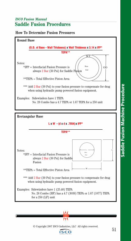
Rectangular Base
LL xx WW -- ((dd xx dd xx ..77885544)) xx IIFFPP**
TTEEPPAA****
Notes:*IFP = Interfacial Fusion Pressure is
always 2 Bar (30 Psi) for Saddle Fusion
**TEPA = Total Effective Piston Area
*** Add 2 Bar (30 Psi) to your fusion pressure to compensate for drag when using hydraulic pump powered fusion equipment.
Examples: Sidewinders have 1 (25.40) TEPANo. 28 Combo (HF) has a 4.7 (3039) TEPA or 1.67 (1077) TEPA for a 250 (LF) unit
ISCO Fusion Manual
51
Sad
dle
Fu
sio
n M
ach
ine
Pro
ced
ure
© Copyright 2007 ISCO Industries, LLC All rights reserved.
Saddle Fusion Procedures
Round Base
((OO..DD.. ooff BBaassee -- WWaallll TThhiicckknneessss)) xx WWaallll TThhiicckknneessss xx 33..1144 xx IIFFPP**
TTEEPPAA****
Notes:*IFP = Interfacial Fusion Pressure is
always 2 Bar (30 Psi) for Saddle Fusion
**TEPA = Total Effective Piston Area
*** Add 2 Bar (30 Psi) to your fusion pressure to compensate for drag when using hydraulic pump powered fusion equipment.
Examples: Sidewinders have 1 TEPANo. 28 Combo has a 4.7 TEPA or 1.67 TEPA for a 250 unit
How To Determine Fusion Pressures
L
BaseEnd
W
d
OD
W.T.
BaseEnd
ISCO Fusion Manual
52
Sadd
le Fusio
n M
achin
e Pro
cedu
re
© Copyright 2007 ISCO Industries, LLC All rights reserved.
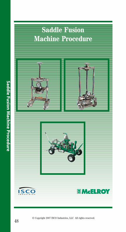
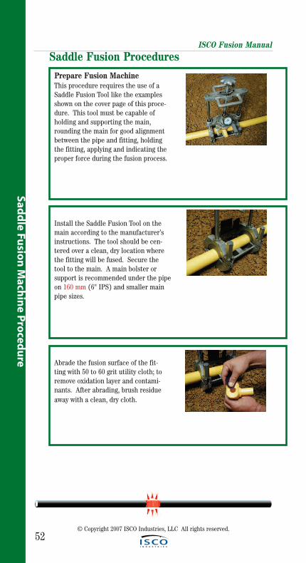
Prepare Fusion MachineThis procedure requires the use of aSaddle Fusion Tool like the examplesshown on the cover page of this proce-dure. This tool must be capable ofholding and supporting the main,rounding the main for good alignmentbetween the pipe and fitting, holdingthe fitting, applying and indicating theproper force during the fusion process.
Install the Saddle Fusion Tool on themain according to the manufacturer’sinstructions. The tool should be cen-tered over a clean, dry location wherethe fitting will be fused. Secure thetool to the main. A main bolster or support is recommended under the pipeon 160 mm (6" IPS) and smaller mainpipe sizes.
Saddle Fusion Procedures
Abrade the fusion surface of the fit-ting with 50 to 60 grit utility cloth; toremove oxidation layer and contami-nants. After abrading, brush residueaway with a clean, dry cloth.
ISCO Fusion Manual
53© Copyright 2007 ISCO Industries, LLC All rights reserved.
Sad
dle
Fu
sio
n M
ach
ine
Pro
ced
ure
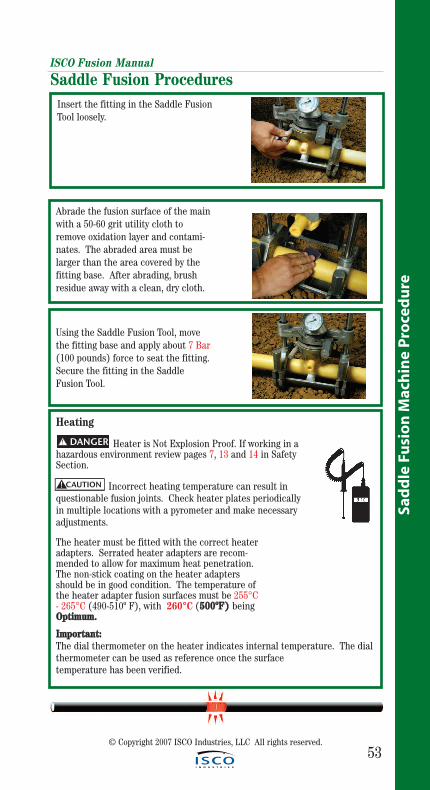
Insert the fitting in the Saddle FusionTool loosely.
Using the Saddle Fusion Tool, movethe fitting base and apply about 7 Bar(100 pounds) force to seat the fitting.Secure the fitting in the SaddleFusion Tool.
Saddle Fusion Procedures
Heating
Heater is Not Explosion Proof. If working in ahazardous environment review pages 7, 13 and 14 in SafetySection.
Incorrect heating temperature can result inquestionable fusion joints. Check heater plates periodicallyin multiple locations with a pyrometer and make necessaryadjustments.
The heater must be fitted with the correct heateradapters. Serrated heater adapters are recom-mended to allow for maximum heat penetration.The non-stick coating on the heater adaptersshould be in good condition. The temperature ofthe heater adapter fusion surfaces must be 255°C- 265°C (490-510º F), with 260°C (550000ººFF)) beingOOppttiimmuumm..
IImmppoorrttaanntt::The dial thermometer on the heater indicates internal temperature. The dialthermometer can be used as reference once the surface temperature has been verified.
CAUTION!
Abrade the fusion surface of the mainwith a 50-60 grit utility cloth toremove oxidation layer and contami-nates. The abraded area must be larger than the area covered by thefitting base. After abrading, brushresidue away with a clean, dry cloth.
! DANGER
ISCO Fusion Manual
54© Copyright 2007 ISCO Industries, LLC All rights reserved.
Sadd
le Fusio
n M
achin
e Pro
cedu
re
Saddle Fusion Procedures
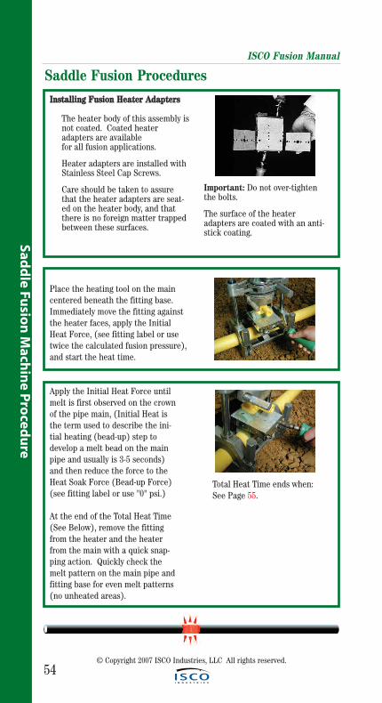
Place the heating tool on the maincentered beneath the fitting base.Immediately move the fitting againstthe heater faces, apply the InitialHeat Force, (see fitting label or usetwice the calculated fusion pressure),and start the heat time.
Apply the Initial Heat Force untilmelt is first observed on the crownof the pipe main, (Initial Heat isthe term used to describe the ini-tial heating (bead-up) step todevelop a melt bead on the mainpipe and usually is 3-5 seconds)and then reduce the force to theHeat Soak Force (Bead-up Force)(see fitting label or use "0" psi.)
At the end of the Total Heat Time (See Below), remove the fittingfrom the heater and the heaterfrom the main with a quick snap-ping action. Quickly check themelt pattern on the main pipe andfitting base for even melt patterns(no unheated areas).
Total Heat Time ends when:See Page 55.
IInnssttaalllliinngg FFuussiioonn HHeeaatteerr AAddaapptteerrss
The heater body of this assembly isnot coated. Coated heater adapters are available for all fusion applications.
Heater adapters are installed with Stainless Steel Cap Screws.
Care should be taken to assure that the heater adapters are seat-ed on the heater body, and that there is no foreign matter trapped between these surfaces.
Important: Do not over-tightenthe bolts.
The surface of the heateradapters are coated with an anti-stick coating.
ISCO Fusion Manual
55
Sad
dle
Fu
sio
n M
ach
ine
Pro
ced
ure
© Copyright 2007 ISCO Industries, LLC All rights reserved.
Saddle Fusion Procedures
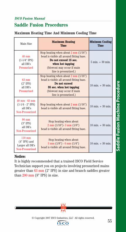
Main SizeMMaaxxiimmuumm HHeeaattiinngg
TTiimmeeMMiinniimmuumm CCoooolliinngg
TTiimmee
40 mm (1-1/4" IPS)
all DR’sPressurized
Stop heating when about 2 mm (1/16") bead is visible all around fitting base.
DDoo nnoott eexxcceeeedd 1155 sseecc.. wwhheenn hhoott ttaappppiinngg
(blowout may occur if mainline is pressurized.)
5 min. + 30 min.
63 mm(2" IPS) all DR’s
Pressurized
Stop heating when about 2 mm (1/16") bead is visible all around fitting base.
DDoo nnoott eexxcceeeedd 3355 sseecc.. wwhheenn hhoott ttaappppiinngg
(blowout may occur if mainline is pressurized.)
10 min. + 30 min.
40 mm - 63 mm(1-1/4 - 2" IPS)
all DR’sNon-Pressurized
Stop heating when about 2 mm (1/16")bead is visible all around fitting base.
10 min. + 30 min.
90 mm(3" IPS)all DR’s
Non-Pressurized
Stop heating when about 2 mm (1/16")- 3 mm (1/8")
bead is visible all around fitting base.10 min. + 30 min.
110 mm(4" IPS) and
Larger all DR’sNon-Pressurized
Stop heating when about 3 mm (1/8") - 6 mm (1/4")
bead is visible all around fitting base.10 min. + 30 min.
Maximum Heating Time And Minimum Cooling Time
NNoottiiccee::It is highly recommended that a trained ISCO Field Service Technician support you on projects involving pressurized mainsgreater than 63 mm (2" IPS) in size and branch saddles greaterthan 200 mm (8" IPS) in size.
ISCO Fusion Manual
56
Sadd
le Fusio
n M
achin
e Pro
cedu
re
© Copyright 2007 ISCO Industries, LLC All rights reserved.
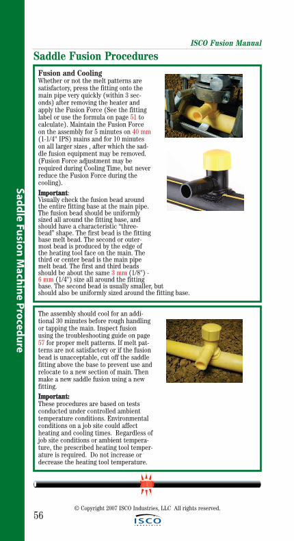
Saddle Fusion ProceduresFusion and CoolingWhether or not the melt patterns aresatisfactory, press the fitting onto themain pipe very quickly (within 3 sec-onds) after removing the heater andapply the Fusion Force (See the fittinglabel or use the formula on page 51 tocalculate). Maintain the Fusion Forceon the assembly for 5 minutes on 40 mm(1-1/4" IPS) mains and for 10 minuteson all larger sizes , after which the sad-dle fusion equipment may be removed.(Fusion Force adjustment may berequired during Cooling Time, but neverreduce the Fusion Force during thecooling). IImmppoorrttaanntt: Visually check the fusion bead aroundthe entire fitting base at the main pipe.The fusion bead should be uniformlysized all around the fitting base, andshould have a characteristic “three-bead” shape. The first bead is the fittingbase melt bead. The second or outer-most bead is produced by the edge ofthe heating tool face on the main. Thethird or center bead is the main pipemelt bead. The first and third beadsshould be about the same 3 mm (1/8") -6 mm (1/4") size all around the fittingbase. The second bead is usually smaller, but should also be uniformly sized around the fitting base.
The assembly should cool for an addi-tional 30 minutes before rough handlingor tapping the main. Inspect fusionusing the troubleshooting guide on page57 for proper melt patterns. If melt pat-terns are not satisfactory or if the fusionbead is unacceptable, cut off the saddlefitting above the base to prevent use andrelocate to a new section of main. Thenmake a new saddle fusion using a newfitting. IImmppoorrttaanntt::These procedures are based on testsconducted under controlled ambienttemperature conditions. Environmentalconditions on a job site could affectheating and cooling times. Regardless ofjob site conditions or ambient tempera-ture, the prescribed heating tool temper-ature is required. Do not increase ordecrease the heating tool temperature.
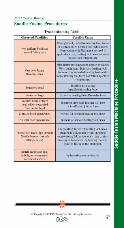
ISCO Fusion Manual
57
Sad
dle
Fu
sio
n M
ach
ine
Pro
ced
ure
© Copyright 2007 ISCO Industries, LLC All rights reserved.
Observed Condition Possible Cause
Non-uniform bead size around fitting base
Misalignment; Defective heating tool; Looseor contaminated heating tool saddle faces;
Worn equipment; Fitting not secured inapplication tool; Heating tool faces not with-
in specified temperature
One bead larger than the other
Misalignment; Component slipped in clamp;Worn equipment; Defective heating tool;
Loose or contaminated heating tool saddlefaces; Heating tool faces not within specified
temperature
Beads too smallInsufficient heating;
Insufficient joining force
Beads too large Excessive heating time; Excessive force
No third bead, or third bead widely separated
from center bead
Incorrect pipe main heating tool face or insufficient joining force
Serrated bead appearance Normal for serrated heating tool faces
Smooth bead appearance Normal for smooth heating tool faces
Pressurized main pipe blowout(beside base or through
fitting center)
Overheating; Incorrect heating tool faces;Heating tool faces not within specified
temperature; Taking too much time to startheating or to remove the heating tool and
join the fitting to the main pipe
Rough, sandpaper-like, bubbly, or pockmarked
melt bead surfaceHydrocarbon contamination
Troubleshooting Guide
Saddle Fusion Procedures
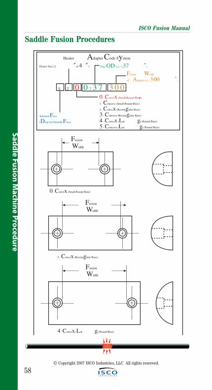
58
ISCO Fusion Manual
Saddle Fusion Procedures
© Copyright 2007 ISCO Industries, LLC All rights reserved.
Sadd
le Fusio
n M
achin
e Pro
cedu
re
FusionWidth
4 - Convex (Lar ge Round Base)
FusionWidth
2 - Convex (Rectangular Base)
FusionWidth
0 - Convex (Small Round Base)
Heater Adapter Code System
S 2 0 0 2 3 7 3 0 0
Heater Size (2 ”or 4 ”)
Serrated Face(Drop for Smooth Face)
Pipe OD (i.e. 2.37 ”)
Fusion Widthof Adapter (i.e. 3.00 ”)
0 - Convex (Small Round Base)1 - Concave (Small Round Base)2 - Convex (Rectangular Base)3 - Concave (Rectangular Base)4 - Convex (Lar ge Round Base)5 - Concave (Lar ge Round Base)
FusionWidth
1 - Concave (Small Round Base)
FusionWidth
3 - Concave (Rectangular Base)
FusionWidth
3 - Concave (Rectangular Base)
FusionWidth
5 - Concave (Lar ge Round Base)
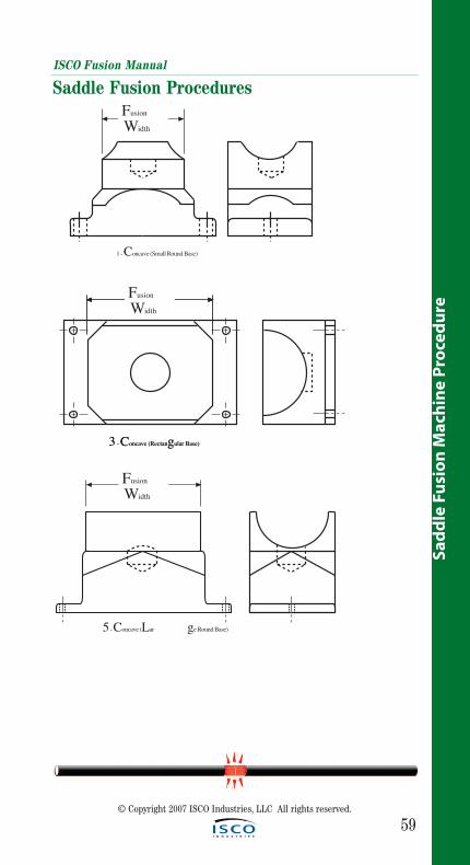
FusionWidth
1 - Concave (Small Round Base)
FusionWidth
3 - Concave (Rectangular Base)
FusionWidth
3 - Concave (Rectangular Base)
FusionWidth
5 - Concave (Lar ge Round Base)
ISCO Fusion Manual
59
Sad
dle
Fu
sio
n M
ach
ine
Pro
ced
ure
© Copyright 2007 ISCO Industries, LLC All rights reserved.
Saddle Fusion Procedures
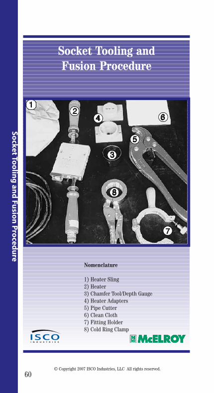
60
Socket To
olin
g an
d Fu
sion
Pro
cedu
re
© Copyright 2007 ISCO Industries, LLC All rights reserved.
Socket Tooling and Fusion Procedure
Nomenclature
1) Heater Sling2) Heater3) Chamfer Tool/Depth Gauge4) Heater Adapters5) Pipe Cutter6) Clean Cloth7) Fitting Holder8) Cold Ring Clamp
12
4
3
8
5
6
7

61
Sock
et T
oo
ling
an
d F
usi
on
Pro
ced
ure
© Copyright 2007 ISCO Industries, LLC All rights reserved.
The theory of heat fusion is to heat twosurfaces to a designed temperature, andthen fuse them together by application offorce. This pressure causes flow of themelted materials, which causes mixing andthus fusion. When the polyethylene mate-rial is heated, the molecular structure istransformed from a crystalline state intoan amorphous condition. When fusionpressure is applied, the molecule fromeach polyethylene part mix. As the jointcools, the molecules return to their crystalline form, the original interfaces are gone, and the fitting and pipe have become one homogeneous unit.
The principle operations include:
Clamping The pipe and fitting must be held firmly to allow all subsequent operations to take place.
Cleaning The area of pipe that the fitting will come in contact with must be cleaned, as well as the base of the fitting.
Alignment The fitting must be properly seated on the pipe for proper alignment.
Heating A melt pattern must be formed that penetrates into the pipe and into the fitting.
Joining The melt patterns must be joined with pressure. The pressure must be constant around the interface area.
Holding The molten joint must be held immobile until adequately cooled.
Socket Tooling and Fusion ProcedureISCO Fusion Manual
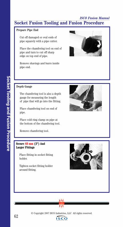
ISCO Fusion Manual
62
Socket To
olin
g an
d Fu
sion
Pro
cedu
re
© Copyright 2007 ISCO Industries, LLC All rights reserved.
Depth Gauge
The chamfering tool is also a depthgauge for measuring the length of pipe that will go into the fitting.
Place chamfering tool on end of pipe.
Place cold ring clamp on pipe at the bottom of the chamfering tool.
Remove chamfering tool.
Prepare Pipe End
Cut off damaged or oval ends of pipe squarely with a pipe cutter.
Place the chamfering tool on end ofpipe and turn to cut off sharp edge on top end of pipe.
Remove shavings and burrs inside pipe end.
SSeeccuurree 6633 mmmm ((22"")) AAnndd LLaarrggeerr FFiittttiinnggss
Place fitting in socket fitting holder.
Tighten socket fitting holder around fitting.
Socket Fusion Tooling and Fusion Procedure
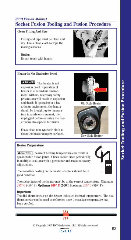
ISCO Fusion Manual
63
Sock
et T
oo
ling
an
d F
usi
on
Pro
ced
ure
© Copyright 2007 ISCO Industries, LLC All rights reserved.
Heater Is Not Explosive Proof
This heater is not explosion proof. Operation of heater in a hazardous environ-ment without necessary safety precautions will result in explosion and death. If operating in a haz-arduous environment the heater should be brought up to tempera-ture in a safe environment, then unplugged before entering the haz-arduous atmosphere for fusion.
Use a clean non-synthetic cloth to clean the heater adapter surfaces.
! DANGER
Clean Fitting And Pipe
Fitting and pipe must be clean and dry. Use a clean cloth to wipe the mating surfaces.
NNoottiiccee: Do not touch with hands.
Socket Fusion Tooling and Fusion Procedure
HHeeaatteerr TTeemmppeerraattuurree
Incorrect heating temperature can result inquestionable fusion joints. Check socket faces periodicallyin multiple locations with a pyrometer and make necessaryadjustments.
The non-stick coating on the heater adapters should be ingood condition.
The socket faces of the heater must be at the correct temperature. Minimum255° C (490° F), OOppttiimmuumm 226600°° CC ((550000°) Maximum 265° C (510° F).
IImmppoorrttaanntt:: The dial thermometer on the heater indicates internal temperature. The dialthermometer can be used as reference once the surface temperature hasbeen verified.
Old Style Heater
New Style Heater
CAUTION!
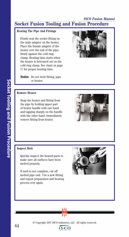
ISCO Fusion Manual
64
Socket To
olin
g an
d Fu
sion
Pro
cedu
re
© Copyright 2007 ISCO Industries, LLC All rights reserved.
Heating The Pipe And Fittings
Firmly seat the socket fitting on the male adapter on the heater. Place the female adapter of the heater over the end of the pipe, firmly against the cold ring clamp. Heating time starts when the heater is bottomed out on the cold ring clamp. See chart on page 67 for proper heating time.
NNoottiiccee: Do not twist fitting, pipe or heater.
Remove Heater
Snap the heater and fitting from the pipe by holding upper part of heater handle with one hand and tapping sharply on the handle with the other hand. Immediately remove fitting from heater.
Inspect Melt
Quickly inspect the heated parts to make sure all surfaces have been melted properly.
If melt is not complete, cut off melted pipe end. Use a new fitting and repeat preparation and heatingprocess over again.
Socket Fusion Tooling and Fusion Procedure
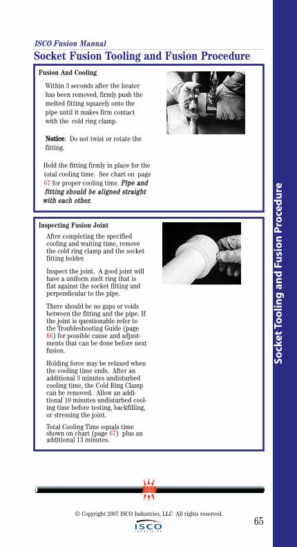
ISCO Fusion Manual
65
Sock
et T
oo
ling
an
d F
usi
on
Pro
ced
ure
© Copyright 2007 ISCO Industries, LLC All rights reserved.
Fusion And Cooling
Within 3 seconds after the heater has been removed, firmly push the melted fitting squarely onto the pipe until it makes firm contact with the cold ring clamp.
NNoottiiccee: Do not twist or rotate the fitting.
Hold the fitting firmly in place for the total cooling time. See chart on page67 for proper cooling time. PPiippee aanndd ffiittttiinngg sshhoouulldd bbee aalliiggnneedd ssttrraaiigghhtt
wwiitthh eeaacchh ootthheerr..
Inspecting Fusion Joint
After completing the specified cooling and waiting time, remove the cold ring clamp and the socket fitting holder.
Inspect the joint. A good joint will have a uniform melt ring that is flat against the socket fitting and perpendicular to the pipe.
There should be no gaps or voids between the fitting and the pipe. Ifthe joint is questionable refer to the Troubleshooting Guide (page 66) for possible cause and adjust-ments that can be done before nextfusion.
Holding force may be relaxed whenthe cooling time ends. After an additional 3 minutes undisturbed cooling time, the Cold Ring Clamp can be removed. Allow an addi-tional 10 minutes undisturbed cool-ing time before testing, backfilling,or stressing the joint.
Total Cooling Time equals time shown on chart (page 67) plus an additional 13 minutes.
Socket Fusion Tooling and Fusion Procedure
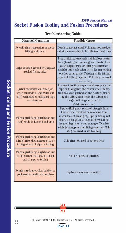
66
ISCO Fusion Manual
Socket To
olin
g an
d Fu
sion
Pro
cedu
re
© Copyright 2007 ISCO Industries, LLC All rights reserved.
Socket Fusion Tooling and Fusion Procedures
Observed Condition Possible Cause
No cold-ring impression in socketfitting melt bead
Depth gauge not used; Cold ring not used, orset at incorrect depth; Insufficient heat time
Gaps or voids around the pipe atsocket fitting edge
Pipe or fitting removed straight from heaterface (twisting or removing from heater face
at an angle); Pipe or fitting not insertedstraight into each other when fusing; joiningtogether at an angle; Twisting while joining
pipe and fitting together; Cold ring not usedor set to deep
(When viewed from inside, orwhen qualifying lengthwise cut
joint) wrinkled or collapsed pipeor tubing end
Incorrect heating sequence-always push thepipe or tubing into the heater after the fit-ting has been pushed on the heater (insert-
ing the tubing first heats the tubing toolong); Cold ring set too deep;
Cold ring not used
(When qualifying lengthwise cutjoint) voids in fusion bond area
Pipe or fitting not removed straight fromheater face (twisting or removing from
heater face at an angle); Pipe or fitting notinserted straight into each other when fus-ing; joining together at an angle; Twisting
while joining pipe and fitting together; Coldring not used or set too deep
(When qualifying lengthwise cutjoint) Unbonded area on pipe ortubing at end of pipe or tubing
Cold ring not used or set too deep
(When qualifying lenghtwise cutjoint) Socket melt extends past
end of pipe or tubingCold ring set too shallow
Rough, sandpaper-like, bubbly, orpockmarked melt bead surface
Hydrocarbon contamination
Troubleshooting Guide
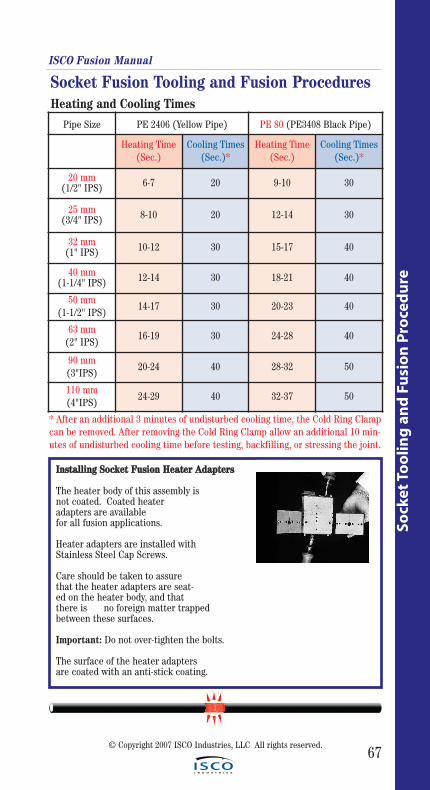
67
Socket Fusion Tooling and Fusion Procedures
Sock
et T
oo
ling
an
d F
usi
on
Pro
ced
ure
Pipe Size PE 2406 (Yellow Pipe) PE 80 (PE3408 Black Pipe)
Heating Time(Sec.)
Cooling Times(Sec.)*
Heating Time(Sec.)
Cooling Times(Sec.)*
20 mm(1/2" IPS) 6-7 20 9-10 30
25 mm(3/4" IPS) 8-10 20 12-14 30
32 mm(1" IPS) 10-12 30 15-17 40
40 mm(1-1/4" IPS) 12-14 30 18-21 40
50 mm(1-1/2" IPS)
14-17 30 20-23 40
63 mm(2" IPS)
16-19 30 24-28 40
90 mm(3"IPS)
20-24 40 28-32 50
110 mm(4"IPS)
24-29 40 32-37 50
Heating and Cooling Times
* After an additional 3 minutes of undisturbed cooling time, the Cold Ring Clampcan be removed. After removing the Cold Ring Clamp allow an additional 10 min-utes of undisturbed cooling time before testing, backfilling, or stressing the joint.
ISCO Fusion Manual
© Copyright 2007 ISCO Industries, LLC All rights reserved.
IInnssttaalllliinngg SSoocckkeett FFuussiioonn HHeeaatteerr AAddaapptteerrss
The heater body of this assembly is not coated. Coated heater adapters are available for all fusion applications.
Heater adapters are installed with Stainless Steel Cap Screws.
Care should be taken to assure that the heater adapters are seat-ed on the heater body, and that there is no foreign matter trapped between these surfaces.
Important: Do not over-tighten the bolts.
The surface of the heater adapters are coated with an anti-stick coating.
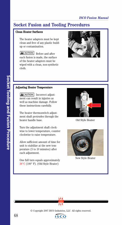
68
Socket To
olin
g an
d Fu
sion
Pro
cedu
re
ISCO Fusion Manual
CClleeaann HHeeaatteerr SSuurrffaacceess
The heater adapters must be kept clean and free of any plastic build-up or contamination.
Before and after each fusion is made, the surface of the heater adapters must be wiped with a clean, non-synthetic cloth.
AAddjjuussttiinngg HHeeaatteerr TTeemmppeerraattuurree
Incorrect adjust-ment can result in injuries as well as machine damage. Follow these instructions carefully.
The heater thermoswitch adjust-ment shaft protrudes through the heater handle base.
Turn the adjustment shaft clock-wise to lower temperature, counterclockwise to raise temperature.
Allow sufficient amount of time forunit to stabilize at the new tem-perature (5 to 10 minutes) after each adjustment.
One full turn equals approximately38°C (100° F). (Old Style Heater)
Socket Fusion and Tooling Procedures
CAUTION!
CAUTION!
Old Style Heater
New Style Heater
© Copyright 2007 ISCO Industries, LLC All rights reserved.

© Copyright 2007 ISCO Industries, LLC All rights reserved.
69
Ref
eren
ce
Reference Information: McElroy DataLogger™,
Pendant/Coach™ Equipment &Fusion Pressure Charts
More helpful Information!
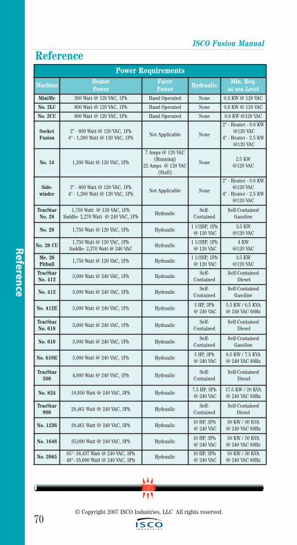
ISCO Fusion Manual
70© Copyright 2007 ISCO Industries, LLC All rights reserved.
Referen
ce
ReferencePower Requirements
MachineHeater Power
Facer Power
HydraulicMin. Req.
at sea LevelMiniMc 300 Watt @ 120 VAC, 1Ph Hand Operated None 0.3 KW @ 120 VAC
No. 2LC 800 Watt @ 120 VAC, 1Ph Hand Operated None 0.8 KW @ 120 VAC
No. 2CU 800 Watt @ 120 VAC, 1Ph Hand Operated None 0.8 KW @120 VAC
SocketFusion
2" - 800 Watt @ 120 VAC, 1Ph4" - 1,200 Watt @ 120 VAC, 1Ph
Not Applicable None
2" - Heater - 0.8 KW@120 VAC
4" - Heater - 2.5 KW@120 VAC
No. 14 1,200 Watt @ 120 VAC, 1Ph
7 Amps @ 120 VAC(Running)
22 Amps @ 120 VAC(Stall)
None2.5 KW
@120 VAC
Side-winder
2" - 800 Watt @ 120 VAC, 1Ph4" - 1,200 Watt @ 120 VAC, 1Ph
Not Applicable None
2" - Heater - 0.8 KW @120 VAC
4" - Heater - 2.5 KW @120 VAC
TracStarNo. 28
1,750 Watt @ 120 VAC, 1PhSaddle- 2,270 Watt @ 240 VAC, 1Ph
HydraulicSelf-
ContainedSelf-Contained
Gasoline
No. 28 1,750 Watt @ 120 VAC, 1Ph Hydraulic1 1/2HP, 1Ph
@ 120 VAC3.5 KW
@120 VAC
No. 28 CU1,750 Watt @ 120 VAC, 1Ph
Saddle- 2,270 Watt @ 240 VACHydraulic
1 1/2HP, 1Ph@ 120 VAC
4 KW @120 VAC
Mc. 28Pitbull
1,750 Watt @ 120 VAC, 1Ph Hydraulic1 1/2HP, 1Ph
@ 120 VAC3.5 KW
@120 VAC
TracStarNo. 412
3,000 Watt @ 240 VAC, 1Ph HydraulicSelf-
ContainedSelf-Contained
Diesel
No. 412 3,000 Watt @ 240 VAC, 1Ph HydraulicSelf-
ContainedSelf-Contained
Gasoline
No. 412E 3,000 Watt @ 240 VAC, 1Ph Hydraulic3 HP, 3Ph@ 240 VAC
5.5 KW / 6.5 KVA @ 240 VAC 60Hz
TracStarNo. 618
3,000 Watt @ 240 VAC, 1Ph HydraulicSelf-
ContainedSelf-Contained
Diesel
No. 618 3,000 Watt @ 240 VAC, 1Ph HydraulicSelf-
ContainedSelf-Contained
Gasoline
No. 618E 3,000 Watt @ 240 VAC, 1Ph Hydraulic5 HP, 3Ph@ 240 VAC
6.5 KW / 7.5 KVA @ 240 VAC 60Hz
TracStar500
4,000 Watt @ 240 VAC, 1Ph HydraulicSelf-
ContainedSelf-Contained
Diesel
No. 824 10,950 Watt @ 240 VAC, 3Ph Hydraulic7.5 HP, 3Ph@ 240 VAC
17.5 KW / 20 KVA @ 240 VAC 60Hz
TracStar900
20,461 Watt @ 240 VAC, 3Ph HydraulicSelf-
ContainedSelf-Contained
Diesel
No. 1236 20,461 Watt @ 240 VAC, 3Ph Hydraulic10 HP, 3Ph@ 240 VAC
30 KW / 30 KVA @ 240 VAC 60Hz
No. 1648 35,000 Watt @ 240 VAC, 3Ph Hydraulic10 HP, 3Ph@ 240 VAC
50 KW / 50 KVA @ 240 VAC 60Hz
No. 206565"- 38,437 Watt @ 240 VAC, 3Ph48"- 35,000 Watt @ 240 VAC, 3Ph
Hydraulic10 HP, 3Ph@ 240 VAC
50 KW / 50 KVA @ 240 VAC 60Hz
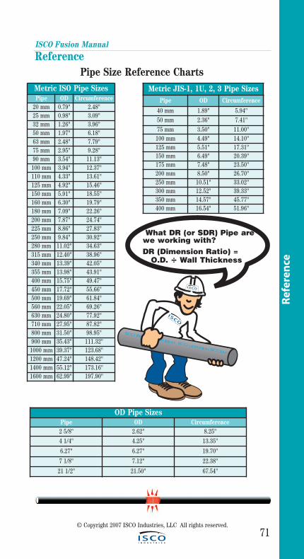
ISCO Fusion Manual
71© Copyright 2007 ISCO Industries, LLC All rights reserved.
Ref
eren
ce
Reference Pipe Size Reference Charts
Metric ISO Pipe SizesPipe OD Circumference
20 mm 0.79" 2.48"25 mm 0.98" 3.09"32 mm 1.26" 3.96"50 mm 1.97" 6.18"63 mm 2.48" 7.79"75 mm 2.95" 9.28"90 mm 3.54" 11.13"100 mm 3.94" 12.37"110 mm 4.33" 13.61"125 mm 4.92" 15.46"150 mm 5.91" 18.55"160 mm 6.30" 19.79"180 mm 7.09" 22.26"200 mm 7.87" 24.74"225 mm 8.86" 27.83"250 mm 9.84" 30.92"280 mm 11.02" 34.63"315 mm 12.40" 38.96"340 mm 13.39" 42.05"355 mm 13.98" 43.91"400 mm 15.75" 49.47"450 mm 17.72" 55.66"500 mm 19.69" 61.84"560 mm 22.05" 69.26"630 mm 24.80" 77.92"710 mm 27.95" 87.82"800 mm 31.50" 98.95"900 mm 35.43" 111.32"1000 mm 39.37" 123.68"1200 mm 47.24" 148.42"1400 mm 55.12" 173.16"1600 mm 62.99" 197.90"
Metric JIS-1, 1U, 2, 3 Pipe SizesPipe OD Circumference
40 mm 1.89" 5.94"50 mm 2.36" 7.41"75 mm 3.50" 11.00"100 mm 4.49" 14.10"125 mm 5.51" 17.31"150 mm 6.49" 20.39"175 mm 7.48" 23.50"200 mm 8.50" 26.70"250 mm 10.51" 33.02"300 mm 12.52" 39.33"350 mm 14.57" 45.77"400 mm 16.54" 51.96"
OD Pipe SizesPipe OD Circumference2 5/8" 2.62" 8.25"
4 1/4" 4.25" 13.35"
6.27" 6.27" 19.70"
7 1/8" 7.12" 22.38"
21 1/2" 21.50" 67.54"
What DR (or SDR) Pipe arewe working with?DR (Dimension Ratio) =
O.D. ÷ Wall Thickness
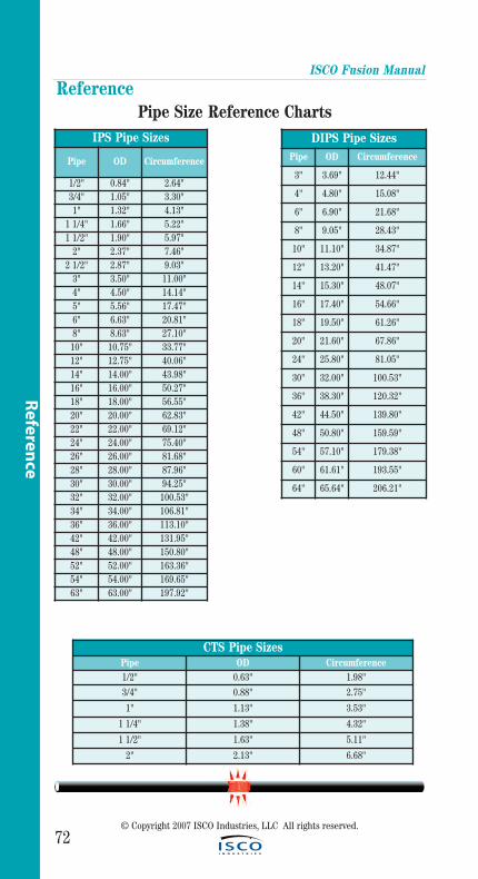
ISCO Fusion Manual
72© Copyright 2007 ISCO Industries, LLC All rights reserved.
Referen
ce
Reference Pipe Size Reference Charts
IPS Pipe Sizes
Pipe OD Circumference
1/2" 0.84" 2.64"3/4" 1.05" 3.30"1" 1.32" 4.13"
1 1/4" 1.66" 5.22"1 1/2" 1.90" 5.97"
2" 2.37" 7.46"2 1/2" 2.87" 9.03"
3" 3.50" 11.00"4" 4.50" 14.14"5" 5.56" 17.47"6" 6.63" 20.81"8" 8.63" 27.10"10" 10.75" 33.77"12" 12.75" 40.06"14" 14.00" 43.98"16" 16.00" 50.27"18" 18.00" 56.55"20" 20.00" 62.83"22" 22.00" 69.12"24" 24.00" 75.40"26" 26.00" 81.68"28" 28.00" 87.96"30" 30.00" 94.25"32" 32.00" 100.53"34" 34.00" 106.81"36" 36.00" 113.10"42" 42.00" 131.95"48" 48.00" 150.80"52" 52.00" 163.36"54" 54.00" 169.65"63" 63.00" 197.92"
DIPS Pipe SizesPipe OD Circumference
3" 3.69" 12.44"
4" 4.80" 15.08"
6" 6.90" 21.68"
8" 9.05" 28.43"
10" 11.10" 34.87"
12" 13.20" 41.47"
14" 15.30" 48.07"
16" 17.40" 54.66"
18" 19.50" 61.26"
20" 21.60" 67.86"
24" 25.80" 81.05"
30" 32.00" 100.53"
36" 38.30" 120.32"
42" 44.50" 139.80"
48" 50.80" 159.59"
54" 57.10" 179.38"
60" 61.61" 193.55"
64" 65.64" 206.21"
CTS Pipe SizesPipe OD Circumference1/2" 0.63" 1.98"
3/4" 0.88" 2.75"
1" 1.13" 3.53"
1 1/4" 1.38" 4.32"
1 1/2" 1.63" 5.11"
2" 2.13" 6.68"
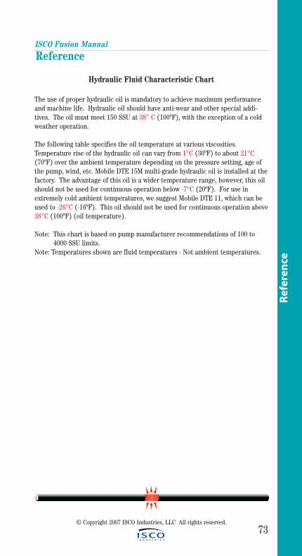
ISCO Fusion Manual
73© Copyright 2007 ISCO Industries, LLC All rights reserved.
Ref
eren
ce
Reference
Hydraulic Fluid Characteristic Chart
The use of proper hydraulic oil is mandatory to achieve maximum performanceand machine life. Hydraulic oil should have anti-wear and other special addi-tives. The oil must meet 150 SSU at 38° C (100ºF), with the exception of a coldweather operation.
The following table specifies the oil temperature at various viscosities.Temperature rise of the hydraulic oil can vary from 1°C (30ºF) to about 21°C(70ºF) over the ambient temperature depending on the pressure setting, age ofthe pump, wind, etc. Mobile DTE 15M multi-grade hydraulic oil is installed at thefactory. The advantage of this oil is a wider temperature range, however, this oilshould not be used for continuous operation below -7°C (20ºF). For use inextremely cold ambient temperatures, we suggest Mobile DTE 11, which can beused to -26°C (-16ºF). This oil should not be used for continuous operation above38°C (100ºF) (oil temperature).
Note: This chart is based on pump manufacturer recommendations of 100 to 4000 SSU limits.
Note: Temperatures shown are fluid temperatures - Not ambient temperatures.
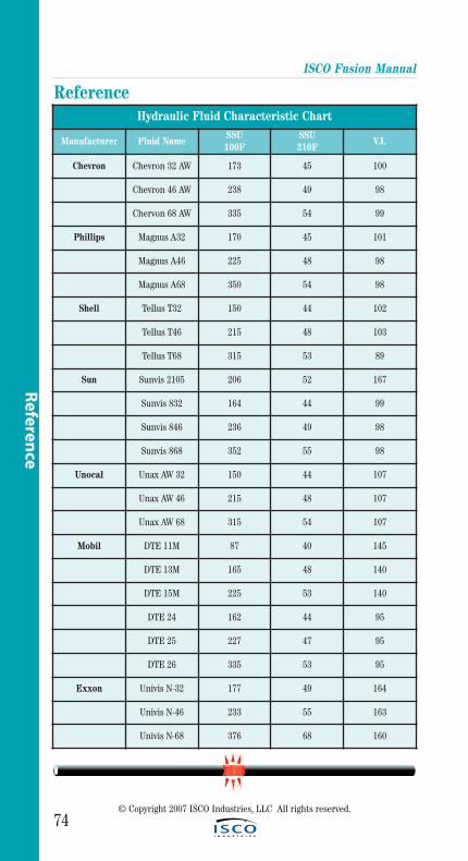
ISCO Fusion Manual
74© Copyright 2007 ISCO Industries, LLC All rights reserved.
Referen
ce
Reference Hydraulic Fluid Characteristic Chart
Manufacturer Fluid NameSSU100F
SSU210F
V.I.
Chevron Chevron 32 AW 173 45 100
Chevron 46 AW 238 49 98
Chervon 68 AW 335 54 99
Phillips Magnus A32 170 45 101
Magnus A46 225 48 98
Magnus A68 350 54 98
Shell Tellus T32 150 44 102
Tellus T46 215 48 103
Tellus T68 315 53 89
Sun Sunvis 2105 206 52 167
Sunvis 832 164 44 99
Sunvis 846 236 49 98
Sunvis 868 352 55 98
Unocal Unax AW 32 150 44 107
Unax AW 46 215 48 107
Unax AW 68 315 54 107
Mobil DTE 11M 87 40 145
DTE 13M 165 48 140
DTE 15M 225 53 140
DTE 24 162 44 95
DTE 25 227 47 95
DTE 26 335 53 95
Exxon Univis N-32 177 49 164
Univis N-46 233 55 163
Univis N-68 376 68 160
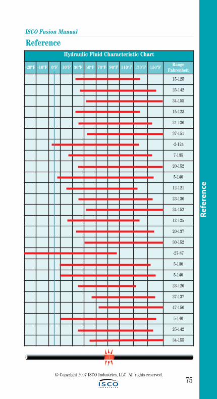
Hydraulic Fluid Characteristic Chart
-20ºF -10ºF 0ºF 10ºF 30ºF 50ºF 70ºF 90ºF 110ºF 130ºF 150ºFRange
Fahrenheit
15-125
25-142
34-155
15-123
24-136
37-151
-2-124
7-135
20-152
5-140
12-121
23-136
34-152
12-125
20-137
30-152
-27-87
5-130
5-140
23-120
37-137
47-150
5-140
25-142
34-155
ISCO Fusion Manual
75© Copyright 2007 ISCO Industries, LLC All rights reserved.
Ref
eren
ce
Reference
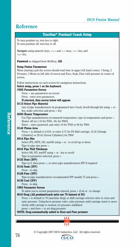
ISCO Fusion Manual
76© Copyright 2007 ISCO Industries, LLC All rights reserved.
Referen
ce
Reference TTrraaccSSttaarr®® PPeennddaanntt// CCooaacchh SSeettuupp
To turn pendant on, turn key to right.To turn pendant off, turn key to off.
Navigate using numeric keys, <+> and <-> keys, <=> key, and <c> key.
PPaasssswwoorrdd as shipped from McElroy, 112233.
SSeettuupp FFuussiioonn PPaarraammeetteerrssWhen starting a job the screen should read time in upper left hand corner. 1 Setup, 2Pressure, 3 Menu on left side of screen and Face, Soak, Fuse with pressure in center ofscreen.
Follow instructions on each screen for navigation instructions.SSeelleecctt sseettuupp,, pprreessss 11 oonn tthhee kkeeyybbooaarrdd..CCOO9922 PPaarraammeetteerrss SSccrreeeenn
Press + use parameters on screen Press - enter new parametersIIff sseelleecctteedd,, tthheenn ssccrreeeenn bbeellooww wwiillll aappppeeaarr..
DD111122 SSeelleecctt PPiippee MMaatteerriiaallList of pipe manufacturers in programmed into Coach, Scroll through list using + or -key, make selection and press = key
SSOO33OO HHeeaatteerr TTeemmppeerraattuurreeUse Pipe manufacturers recommend temperature, type in temperature and press =Heater off set (-10 for T500, -60, for T900)Enter -, enter password, and enter 10 for T500 or 60 for T900
DD114400 PPiissttoonn AArreeaaPress = to default to 6.010, or enter 4.71 for Pit Bull carriage, 15.32 (Orange Cylinders) or 29.44 (Green Cylinders) for T900
SSOO1144 PPiippee SSiizzeeSelect IPS, DIPS, OD, mmOD using + or - to scroll up or downType in pipe size press =
SSOO1188 PPiippee WWaallll TThhiicckknneessssSelect DR, WT, mmWT using + or - key to scrollType in parameter selected, press =
DD112222 HHeeaatt ((IIFFPP))Type in 0, then press =, or enter pipe manufacturers IFP if required
DD112244 SSooaakk ((IIFFPP))Press - to skip
DD112266 FFuussee ((IIFFPP))Type in pipe manufacturers recommended IFP usually 75 and press =
DD112288 CCooooll ((IIFFPP))Press - to skip
CC009922 PPaarraammeetteerr SSccrreeeennTo allow you to review parameters entered, press + if ok or - to change
SS001100 DDrraagg ((AAllll ppeennddaanntt//ccooaacchh uunniittss uussee 7700 iinnsstteeaadd ooff 3300))Press + to default to 70 (machine drag) or shift carriage selector valve to close and raise pressure. Using facer pressure valve, raise pressure until carriage starts to moveslowly, shift carriage to neutral, let pressure stabilizedpress + and then = to set drag pressure
NNOOTTEE:: DDrraagg aauuttoommaattiiccaallllyy aaddddeedd ttoo HHeeaatt aanndd FFuussee pprreessssuurree
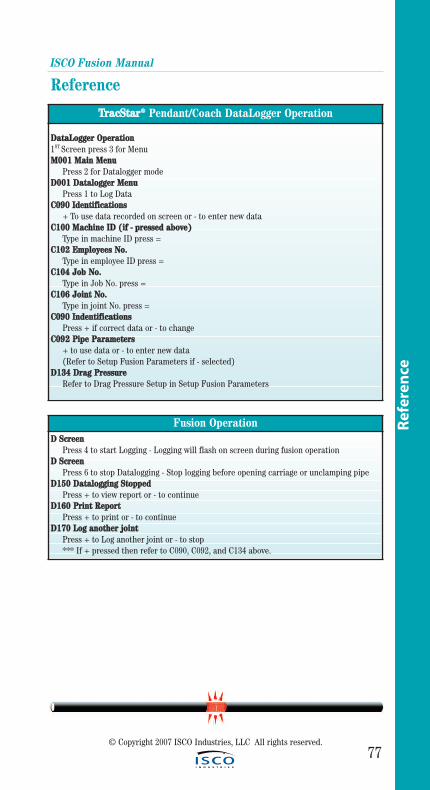
ISCO Fusion Manual
77© Copyright 2007 ISCO Industries, LLC All rights reserved.
Ref
eren
ce
Reference
TTrraaccSSttaarr®® Pendant/Coach DataLogger Operation
DDaattaaLLooggggeerr OOppeerraattiioonn1ST Screen press 3 for MenuMM000011 MMaaiinn MMeennuu
Press 2 for Datalogger modeDD000011 DDaattaallooggggeerr MMeennuu
Press 1 to Log DataCC009900 IIddeennttiiffiiccaattiioonnss
+ To use data recorded on screen or - to enter new dataCC110000 MMaacchhiinnee IIDD ((iiff -- pprreesssseedd aabboovvee))
Type in machine ID press =CC110022 EEmmppllooyyeeeess NNoo..
Type in employee ID press = CC110044 JJoobb NNoo..
Type in Job No. press =CC110066 JJooiinntt NNoo..
Type in joint No. press = CC009900 IInnddeennttiiffiiccaattiioonnss
Press + if correct data or - to changeCC009922 PPiippee PPaarraammeetteerrss
+ to use data or - to enter new data(Refer to Setup Fusion Parameters if - selected)
DD113344 DDrraagg PPrreessssuurreeRefer to Drag Pressure Setup in Setup Fusion Parameters
Fusion OperationDD SSccrreeeenn
Press 4 to start Logging - Logging will flash on screen during fusion operationDD SSccrreeeenn
Press 6 to stop Datalogging - Stop logging before opening carriage or unclamping pipeDD115500 DDaattaallooggggiinngg SSttooppppeedd
Press + to view report or - to continueDD116600 PPrriinntt RReeppoorrtt
Press + to print or - to continueDD117700 LLoogg aannootthheerr jjooiinntt
Press + to Log another joint or - to stop*** If + pressed then refer to C090, C092, and C134 above.
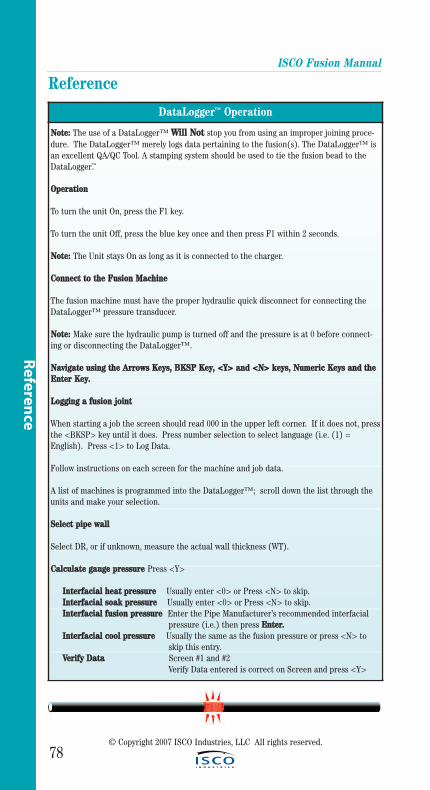
78
ISCO Fusion Manual
Reference
DataLogger™ Operation
NNoottee:: The use of a DataLogger™ WWiillll NNoott stop you from using an improper joining proce-dure. The DataLogger™ merely logs data pertaining to the fusion(s). The DataLogger™ isan excellent QA/QC Tool. A stamping system should be used to tie the fusion bead to theDataLogger™.
OOppeerraattiioonn
To turn the unit On, press the F1 key.
To turn the unit Off, press the blue key once and then press F1 within 2 seconds.
NNoottee:: The Unit stays On as long as it is connected to the charger.
CCoonnnneecctt ttoo tthhee FFuussiioonn MMaacchhiinnee
The fusion machine must have the proper hydraulic quick disconnect for connecting theDataLogger™ pressure transducer.
NNoottee:: Make sure the hydraulic pump is turned off and the pressure is at 0 before connect-ing or disconnecting the DataLogger™.
NNaavviiggaattee uussiinngg tthhee AArrrroowwss KKeeyyss,, BBKKSSPP KKeeyy,, <<YY>> aanndd <<NN>> kkeeyyss,, NNuummeerriicc KKeeyyss aanndd tthheeEEnntteerr KKeeyy..
LLooggggiinngg aa ffuussiioonn jjooiinntt
When starting a job the screen should read 000 in the upper left corner. If it does not, pressthe <BKSP> key until it does. Press number selection to select language (i.e. (1) =English). Press <1> to Log Data.
Follow instructions on each screen for the machine and job data.
A list of machines is programmed into the DataLogger™; scroll down the list through theunits and make your selection.
SSeelleecctt ppiippee wwaallll
Select DR, or if unknown, measure the actual wall thickness (WT).
CCaallccuullaattee ggaauuggee pprreessssuurree Press <Y>
IInntteerrffaacciiaall hheeaatt pprreessssuurree Usually enter <0> or Press <N> to skip.IInntteerrffaacciiaall ssooaakk pprreessssuurree Usually enter <0> or Press <N> to skip.IInntteerrffaacciiaall ffuussiioonn pprreessssuurree Enter the Pipe Manufacturer’s recommended interfacial
pressure (i.e.) then press EEnntteerr..IInntteerrffaacciiaall ccooooll pprreessssuurree Usually the same as the fusion pressure or press <N> to
skip this entry.VVeerriiffyy DDaattaa Screen #1 and #2
Verify Data entered is correct on Screen and press <Y>
Referen
ce
© Copyright 2007 ISCO Industries, LLC All rights reserved.
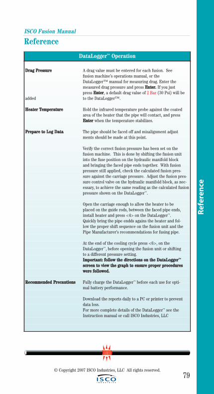
79
ISCO Fusion Manual
Reference
Ref
eren
ce
DataLogger™ Operation
DDrraagg PPrreessssuurree A drag value must be entered for each fusion. See fusion machine’s operations manual, or the DataLogger™ manual for measuring drag. Enter the measured drag pressure and press EEnntteerr.. If you just press EEnntteerr, a default drag value of 2 Bar (30 Psi) will be
added to the DataLogger™.
HHeeaatteerr TTeemmppeerraattuurree Hold the infrared temperature probe against the coated area of the heater that the pipe will contact, and press EEnntteerr when the temperature stabilizes.
PPrreeppaarree ttoo LLoogg DDaattaa The pipe should be faced off and misalignment adjustments should be made at this point.
Verify the correct fusion pressure has been set on the fusion machine. This is done by shifting the fusion unit into the fuse position on the hydraulic manifold block and bringing the faced pipe ends together. With fusion pressure still applied, check the calculated fusion pres-sure against the carriage pressure. Adjust the fusion pres-sure control valve on the hydraulic manifold block, as nec-essary, to achieve the same reading as the calculated fusionpressure shown on the DataLogger™.
Open the carriage enough to allow the heater to be placed on the guide rods, between the faced pipe ends, install heater and press <4> on the DataLogger™. Quickly bring the pipe endds agains the heater and fol-low the proper shift sequence on the fusion unit and the Pipe Manufacturer’s recommendations for fusing pipe.
At the end of the cooling cycle press <6>, on the DataLogger™, before opening the fusion unit or shifting to a different pressure setting. IImmppoorrttaanntt:: ffoollllooww tthhee ddiirreeccttiioonnss oonn tthhee DDaattaaLLooggggeerr™™
ssccrreeeenn ttoo vviieeww tthhee ggrraapphh ttoo eennssuurree pprrooppeerr pprroocceedduurreess wweerree ffoolllloowweedd..
RReeccoommmmeennddeedd PPrreeccaauuttiioonnss Fully charge the DataLogger™ before each use for opti-mal battery performance.
Download the reports daily to a PC or printer to prevent data loss. For more complete details of the DataLogger™ see the Instruction manual or call ISCO Industries, LLC
© Copyright 2007 ISCO Industries, LLC All rights reserved.
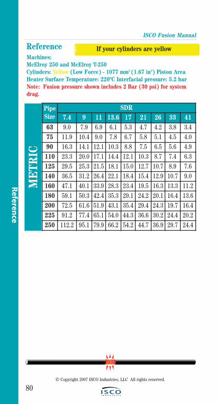
ISCO Fusion Manual
80
Referen
ce
Reference M
ETR
IC
Machines:McElroy 250 and McElroy T-250Cylinders: Yellow (Low Force) - 1077 mm2 (1.67 in2) Piston AreaHeater Surface Temperature: 220ºC Interfacial pressure: 5.2 barNote: Fusion pressure shown includes 2 Bar (30 psi) for systemdrag.
© Copyright 2007 ISCO Industries, LLC All rights reserved.
If your cylinders are yellow
PipeSize
SDR7.4 9 11 13.6 17 21 26 33 41
63 9.0 7.9 6.9 6.1 5.3 4.7 4.2 3.8 3.475 11.9 10.4 9.0 7.8 6.7 5.8 5.1 4.5 4.090 16.3 14.1 12.1 10.3 8.8 7.5 6.5 5.6 4.9110 23.3 20.0 17.1 14.4 12.1 10.3 8.7 7.4 6.3125 29.5 25.3 21.5 18.1 15.0 12.7 10.7 8.9 7.6140 36.5 31.2 26.4 22.1 18.4 15.4 12.9 10.7 9.0160 47.1 40.1 33.9 28.3 23.4 19.5 16.3 13.3 11.2180 59.1 50.3 42.4 35.3 29.1 24.2 20.1 16.4 13.6200 72.5 61.6 51.9 43.1 35.4 29.4 24.3 19.7 16.4225 91.2 77.4 65.1 54.0 44.3 36.6 30.2 24.4 20.2250 112.2 95.1 79.9 66.2 54.2 44.7 36.9 29.7 24.4
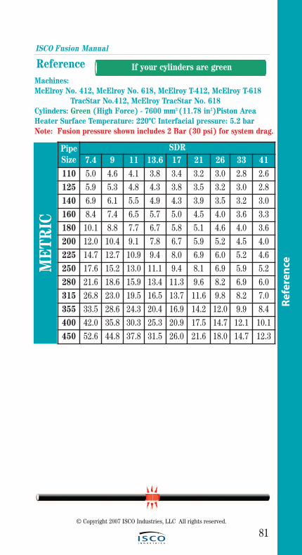
ISCO Fusion Manual
81
ReferenceMachines:McElroy No. 412, McElroy No. 618, McElroy T-412, McElroy T-618
TracStar No.412, McElroy TracStar No. 618Cylinders: Green (High Force) - 7600 mm2 (11.78 in2)Piston AreaHeater Surface Temperature: 220ºC Interfacial pressure: 5.2 barNote: Fusion pressure shown includes 2 Bar (30 psi) for system drag.
© Copyright 2007 ISCO Industries, LLC All rights reserved.
If your cylinders are green
Ref
eren
ceME
TRIC
PipeSize
SDR7.4 9 11 13.6 17 21 26 33 41
110 5.0 4.6 4.1 3.8 3.4 3.2 3.0 2.8 2.6
125 5.9 5.3 4.8 4.3 3.8 3.5 3.2 3.0 2.8
140 6.9 6.1 5.5 4.9 4.3 3.9 3.5 3.2 3.0
160 8.4 7.4 6.5 5.7 5.0 4.5 4.0 3.6 3.3
180 10.1 8.8 7.7 6.7 5.8 5.1 4.6 4.0 3.6
200 12.0 10.4 9.1 7.8 6.7 5.9 5.2 4.5 4.0
225 14.7 12.7 10.9 9.4 8.0 6.9 6.0 5.2 4.6
250 17.6 15.2 13.0 11.1 9.4 8.1 6.9 5.9 5.2
280 21.6 18.6 15.9 13.4 11.3 9.6 8.2 6.9 6.0
315 26.8 23.0 19.5 16.5 13.7 11.6 9.8 8.2 7.0
355 33.5 28.6 24.3 20.4 16.9 14.2 12.0 9.9 8.4
400 42.0 35.8 30.3 25.3 20.9 17.5 14.7 12.1 10.1
450 52.6 44.8 37.8 31.5 26.0 21.6 18.0 14.7 12.3
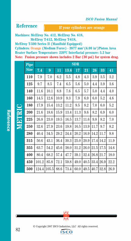
ISCO Fusion Manual
82
Referen
ce
Reference
Machines: McElroy No. 412, McElroy No. 618, McElroy T-412, McElroy T-618,
McElroy T-500 Series II (Manifold Equipped)Cylinders: Orange (Medium Force) - 3877 mm2 (6.00 in2)Piston AreaHeater Surface Temperature: 220ºC Interfacial pressure: 5.2 barNote: Fusion pressure shown includes 2 Bar (30 psi) for system drag.
© Copyright 2007 ISCO Industries, LLC All rights reserved.
If your cylinders are orange
ME
TRIC
PipeSize
SDR
7.4 9 11 13.6 17 21 26 33 41
110 7.9 7.0 6.2 5.5 4.8 4.3 3.9 3.5 3.2
125 9.7 8.5 7.4 6.5 5.6 5.0 4.4 3.9 3.6
140 11.6 10.1 8.8 7.6 6.5 5.7 5.0 4.4 4.0
160 14.5 12.6 10.9 9.3 7.9 6.9 6.0 5.2 4.6
180 17.9 15.4 13.2 11.2 9.5 8.2 7.0 6.0 5.2
200 21.6 18.6 15.9 13.4 11.3 9.6 8.2 6.9 6.0
225 26.8 23.0 19.5 16.5 13.7 11.6 9.8 8.2 7.0
250 32.6 27.9 23.6 19.8 16.5 13.9 11.7 9.7 8.2
280 40.4 34.5 29.2 24.4 20.2 16.9 14.2 11.7 9.8
315 50.6 43.1 36.4 30.3 25.0 20.9 17.4 14.2 11.9
355 63.7 54.2 45.6 38.0 31.2 26.0 21.5 17.5 14.6
400 80.4 68.2 57.4 47.7 39.1 32.4 26.8 21.7 18.0
450 101.2 85.8 72.1 59.8 49.0 40.5 33.4 26.9 22.2
500 124.4 105.5 88.6 73.4 60.0 49.5 40.7 32.8 26.9
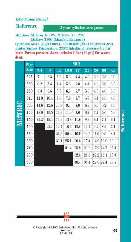
ISCO Fusion Manual
83
Reference
Machines: McElroy No. 824, McElroy No. 1236, McElroy T-900 (Manifold Equipped)
Cylinders: Green (High Force) - 19000 mm2 (29.44 in2)Piston AreaHeater Surface Temperature: 220ºC Interfacial pressure: 5.2 barNote: Fusion pressure shown includes 2 Bar (30 psi) for systemdrag.
© Copyright 2007 ISCO Industries, LLC All rights reserved.
If your cylinders are green
Ref
eren
ce
ME
TRIC
PipeSize
SDR
7.4 9 11 13.6 17 21 26 33 41
225 7.1 6.3 5.6 5.0 4.4 4.0 3.6 3.3 3.0
250 8.2 7.3 6.4 5.6 5.0 4.4 4.0 3.6 3.3
280 9.8 8.6 7.5 6.6 5.7 5.0 4.5 4.0 3.6
315 11.9 10.4 9.0 7.8 6.7 5.8 5.1 4.5 4.0
355 14.6 12.6 10.9 9.3 8.0 6.9 6.0 5.2 4.6
400 18.0 15.5 13.3 11.3 9.6 8.2 7.1 6.0 5.3
450 22.2 19.1 16.3 13.8 11.6 9.9 8.4 7.1 6.1
500 23.1 19.7 16.6 13.8 11.7 9.9 8.3 7.1
560 24.2 20.3 16.9 14.2 11.9 9.9 8.4
630 30.1 25.1 20.8 17.4 14.6 12.0 10.1
710 31.4 25.9 21.6 17.9 14.7 12.3
800 32.3 26.8 22.2 18.1 15.0
900 40.4 33.4 27.6 22.4 18.5
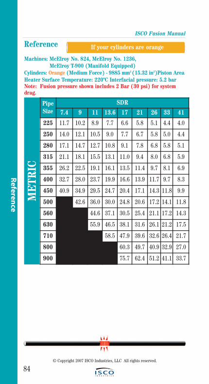
ISCO Fusion Manual
84
Referen
ce
Reference
Machines: McElroy No. 824, McElroy No. 1236, McElroy T-900 (Manifold Equipped)
Cylinders: Orange (Medium Force) - 9885 mm2 (15.32 in2)Piston AreaHeater Surface Temperature: 220ºC Interfacial pressure: 5.2 barNote: Fusion pressure shown includes 2 Bar (30 psi) for systemdrag.
© Copyright 2007 ISCO Industries, LLC All rights reserved.
If your cylinders are orange
ME
TRIC
PipeSize
SDR
7.4 9 11 13.6 17 21 26 33 41
225 11.7 10.2 8.9 7.7 6.6 5.8 5.1 4.4 4.0
250 14.0 12.1 10.5 9.0 7.7 6.7 5.8 5.0 4.4
280 17.1 14.7 12.7 10.8 9.1 7.8 6.8 5.8 5.1
315 21.1 18.1 15.5 13.1 11.0 9.4 8.0 6.8 5.9
355 26.2 22.5 19.1 16.1 13.5 11.4 9.7 8.1 6.9
400 32.7 28.0 23.7 19.9 16.6 13.9 11.7 9.7 8.3
450 40.9 34.9 29.5 24.7 20.4 17.1 14.3 11.8 9.9
500 42.6 36.0 30.0 24.8 20.6 17.2 14.1 11.8
560 44.6 37.1 30.5 25.4 21.1 17.2 14.3
630 55.9 46.5 38.1 31.6 26.1 21.2 17.5
710 58.5 47.9 39.6 32.6 26.4 21.7
800 60.3 49.7 40.9 32.9 27.0
900 75.7 62.4 51.2 41.1 33.7
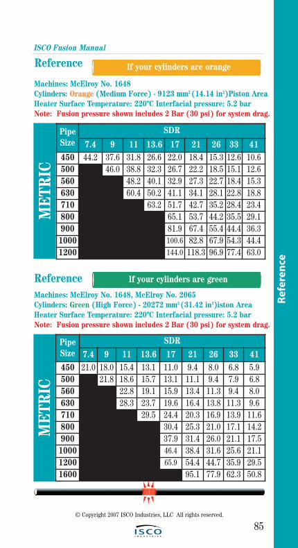
ISCO Fusion Manual
85
Reference
Machines: McElroy No. 1648 Cylinders: Orange (Medium Force) - 9123 mm2 (14.14 in2)Piston AreaHeater Surface Temperature: 220ºC Interfacial pressure: 5.2 barNote: Fusion pressure shown includes 2 Bar (30 psi) for system drag.
© Copyright 2007 ISCO Industries, LLC All rights reserved.
If your cylinders are greenR
efer
ence
ME
TRIC
PipeSize
SDR
7.4 9 11 13.6 17 21 26 33 41450 44.2 37.6 31.8 26.6 22.0 18.4 15.3 12.6 10.6500 46.0 38.8 32.3 26.7 22.2 18.5 15.1 12.6560 48.2 40.1 32.9 27.3 22.7 18.4 15.3630 60.4 50.2 41.1 34.1 28.1 22.8 18.8710 63.2 51.7 42.7 35.2 28.4 23.4800 65.1 53.7 44.2 35.5 29.1900 81.9 67.4 55.4 44.4 36.3
1000 100.6 82.8 67.9 54.3 44.41200 144.0 118.3 96.9 77.4 63.0
If your cylinders are orange
ReferenceMachines: McElroy No. 1648, McElroy No. 2065 Cylinders: Green (High Force) - 20272 mm2 (31.42 in2)iston AreaHeater Surface Temperature: 220ºC Interfacial pressure: 5.2 barNote: Fusion pressure shown includes 2 Bar (30 psi) for system drag.
ME
TRIC
PipeSize
SDR
7.4 9 11 13.6 17 21 26 33 41450 21.0 18.0 15.4 13.1 11.0 9.4 8.0 6.8 5.9500 21.8 18.6 15.7 13.1 11.1 9.4 7.9 6.8560 22.8 19.1 15.9 13.4 11.3 9.4 8.0630 28.3 23.7 19.6 16.4 13.8 11.3 9.6710 29.5 24.4 20.3 16.9 13.9 11.6800 30.4 25.3 21.0 17.1 14.2900 37.9 31.4 26.0 21.1 17.51000 46.4 38.4 31.6 25.6 21.11200 65.9 54.4 44.7 35.9 29.51600 95.1 77.9 62.3 50.8
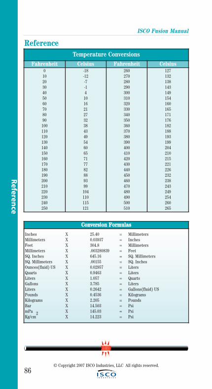
ISCO Fusion Manual
86© Copyright 2007 ISCO Industries, LLC All rights reserved.
ReferenceTemperature Conversions
Fahrenheit Celsius Fahrenheit Celsius0102030405060708090100110120130140150160170180190200210220230240250
-18-12-7-141016212732384349546065717782889399104110115121
260270280290300310320330340350360370380390400410420430440450460470480490500510
127132138143149154160165171176182188193199204210215221226232238243249254260265
CCoonnvveerrssiioonn FFoorrmmuullaass
Inches X 25.40 = MillimetersMillimeters X 0.03937 = InchesFeet X 304.8 = MillimetersMillimeters X .003280839 = FeetSQ. Inches X 645.16 = SQ. MillimetersSQ. Millimeters X .00155 = SQ. InchesOunces(fluid) US X 0.02957 = LitersQuarts X 0.9463 = LitersLiters X 1.057 = QuartsGallons X 3.785 = LitersLiters X 0.2642 = Gallons(fluid) USPounds X 0.4536 = KilogramsKilograms X 2.205 = PoundsBar X 14.503 = PsimPa X 145.03 = PsiKg/cm
2X 14.223 = Psi
Referen
ce
ISCO Fusion Manual
87© Copyright 2007 ISCO Industries, LLC All rights reserved.
Ref
eren
ce
ReferenceRReeffeerreenncceess
1. Plastics Pipe Institute Technical Report-33. Generic Butt Fusion Joining Procedure for Polyethylene Gas Pipe, 2001
2. Plastics Pipe Institute Technical Report-41. Generic Saddle Fusion Joining Procedure for Polyethylene Gas Pipe, 2002
3. Plastics Pipe Institute. Polyethylene Joining Procedures, March 1998.
4. ASTM D2657-97. Standard Practice for Heat Fusion Joining of Polyolefin Pipe and Fittings. Volume 8.04. American Society of Testing and Materials. Baltimore, 2002.
5. ASTM F1056-97. Standard Specification for Socket Fusion Tools for Use in Socket Fusion Joining Polyethylene Pipe or Tubing and Fittings. Volume 8.04. American Society of Testing and Materials. Baltimore, 2002.
6. Pipeline Safety Regulations. U.S. Department of Transportation. CFR 49. Washington, 2002.

ISCO Fusion Manual
88© Copyright 2007 ISCO Industries, LLC All rights reserved.
Notes

NotesISCO Fusion Manual
89© Copyright 2007 ISCO Industries, LLC All rights reserved.
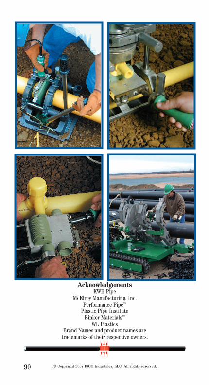
90 © Copyright 2007 ISCO Industries, LLC All rights reserved.
AcknowledgementsKWH Pipe
McElroy Manufacturing, Inc.Performance Pipe™
Plastic Pipe InstituteRinker Materials™
WL PlasticsBrand Names and product names are
trademarks of their respective owners.