function range resolution - instrumart · 2009-04-30 · function range resolution measure v dc 28...
TRANSCRIPT

English Instruction SheetPanel 1
®
707 Loop Calibrator
Instruction Sheet
Introduction The Fluke 707 Loop Calibrator (hereafter, the Calibrator) is a compact sourcing and measuring tool. The Calibrator tests current loops of 0-20 mA or 4-20 mA and measures dc voltage to 28 V. It comes with a set of alligator-clip test leads, a 9 V alkaline battery, and this Instruction Sheet. The Calibrator is a IEC 61010, CAT I 30 V, Pollution Degree 2 instrument. A CAT I instrument is designed to protect against transients from high-voltage, low-energy sources, like electronic circuits or a copy machine, for example.
Calibrator Capabilities Function Range Resolution
Measure V dc 28 V 1 mV Measure mA dc Source mA dc
0 to 24 mA 1 μA
Source loop power 24 V dc N/A
Battery Saver The Calibrator automatically turns off after 30 minutes of inactivity. To reduce this time or disable this feature: 1. With the Calibrator OFF, press D.
PSXX is displayed, where XX is the turn-off time in minutes. OFF means the power saver is disabled.
2. Turn m to decrease or increase the turn-off time. To disable, turn m until the display shows OFF.
3. The Calibrator resumes normal operation after 2 seconds. August 2001 (English) Rev. 2, 2/08 © 2001-2008 Fluke Corporation. Product specifications are subject to change without notice. All rights reserved.

English Instruction SheetPanel 2
W Warnings and Cautions To avoid electric shock, injury, or damage to the Calibrator: • Use the Calibrator only as described in this
Instruction Sheet or the protection provided by the Calibrator may be impaired.
• Do not use the Calibrator around explosive gas, vapor, or dust.
• Inspect the Calibrator before use. Do not use it if appears damaged.
• Check the test leads for continuity, damaged insulation, or exposed metal. Replace damaged test leads.
• Never apply more than 30 V between any two terminals, or between any terminal and earth ground.
• Use the proper terminals, mode, and range for your measuring or sourcing application.
• To prevent damage to the unit under test, put the Calibrator in the correct mode before connecting the test leads.
• When making connections, connect the COM test lead before the live lead; when disconnecting, disconnect the live lead before the COM lead.
• Never use the Calibrator with the case open. • Make sure the battery door is closed before you
use the Calibrator. • Replace the battery as soon as the M (low battery)
symbol appears to avoid false readings that can lead to electric shock.
• Remove test leads from the Calibrator before opening the case or battery door.
Symbols Symbol Meaning
+ ON / OFF button.
J Earth ground
W Caution: Important information. Refer to instruction sheet
h Caution: Static discharge can damage parts
T Double insulated
M Battery
) Conforms to relevant Canadian Standards Association directives. Certification # LR110460-2.
P Conforms to European Union requirements
F Direct current
~ Do not dispose of this product as unsorted municipal waste. Go to Fluke’s web site for recycling information.

English Instruction SheetPanel 3
Pushbutton Functions Pushbutton Function
D ON or OFF button.
A + D
(Power-on Option)
Press A and D simultaneously to toggle between the mA output spans.
• 4 mA to 20 mA = 0 % - 100 % (default)
• 0 mA to 20 mA = 0 % - 100 % (optional)
The selection is saved until it is changed.
l + D (Power-on Option)
Press l + D simultaneously to turn HART resistor (Hr) on. Default is off.
A Press to step through modes:
• Source mA
• Simulate mA
• Measure mA
• Loop Power (24 V)
• Measure V dc
h i j
Turn n to increase or decrease current output.
Current output can be adjusted at a resolution of 1 μA or 100 μA. (Default is 1 μA.)
• To adjust the current in 1 μA steps, simply turn the knob.
• To adjust the current in 100 μA steps, press in and turn the knob.
B Press B to step the current up 25 % of full scale (20 mA).
At full scale, press B to step the current down 25 % of full scale.
B+ C Press B + C simultaneously to enter the Auto Ramp mode and select a ramp form.
A continuously applied or controlled mA ramping signal is produced in one of three ramp forms.
e (slow), g (fast), or f (step) identifies the selected ramp form.
C Press C to start the SpanCheck™ at 0 % of selected current span, i.e., 0 mA for 0-20 mA span or 4 mA for 4-20 mA span.
d is displayed.
Press again for 100 % of selected current span.

English Instruction SheetPanel 4
Using the mA Sourcing (Output) Modes The Calibrator outputs current for calibrating and testing 0 to 20 mA and 4 to 20 mA current loops and instruments. In SOURCE mode, the Calibrator supplies the current. In SIMULATE mode, the Calibrator simulates a 2-wire transmitter in an externally-powered current loop.
Changing the mA Output Span The Calibrator has two mA output spans: • 4 mA to 20 mA (0 % to 100 %) [default] • 0 mA to 20 mA (0 % to 100 %) [optional] To change the output span, turn the Calibrator off. Press A + D simultaneously. The selected setting is saved until it is changed again.
Sourcing mA Use SOURCE mode to supply current to a passive circuit. A path must exist for current to flow between the + and COM terminals. Otherwise the display indicates an overload (OL) when you set an output value.
COM +
707 LOOP CALIBRATOR
30VCAT
Press until SOURCEmA is displayed.
Press to step currentup/down in 25 % steps of full scale.
Turn to step up/down1 A. Press in and turn to step up/downin 100 A increments.
Press simultaneouslyonce for slow ramptwice for fast rampthree times forstepped ramp.
ADA04F.EPS

English Instruction SheetPanel 5
Contacting Fluke To contact Fluke for product information, operating assistance, service, or to get the location of the nearest Fluke distributor or service center, call:
1-888-44-FLUKE (1-888-443-5853) in U.S.A 1-800-36-FLUKE in Canada +31-402-675-200 in Europe +81-3-3434-0181 Japan +65-738-5655 Singapore +1-425-446-5500 from other countries
Or visit Fluke's web site at: www.fluke.com. Register your Calibrator at: http://register.fluke.com. Address correspondence to:
Fluke Corporation Fluke Europe B.V. P.O. Box 9090, P.O. Box 1186, Everett, WA 98206-9090 5602 BD Eindhoven U.S.A. The Netherlands
Limited Warranty & Limitation Of Liability
This Fluke product will be free from defects in material and work-manship for 3 years from the date of purchase. This warranty does not cover fuses, disposable batteries, or damage from accident, neglect, misuse, alteration, contamination, or abnormal conditions of operation or handling. Resellers are not authorized to extend any other warranty on Fluke’s behalf. To obtain service during the warranty period, contact your nearest Fluke authorized service center to obtain return authorization information, then send the product to that Service Center with a description of the problem. THIS WARRANTY IS YOUR ONLY REMEDY. NO OTHER WARRANTIES, SUCH AS FITNESS FOR A PARTICULAR PURPOSE, ARE EXPRESSED OR IMPLIED. FLUKE IS NOT LIABLE FOR ANY SPECIAL, INDIRECT, INCIDENTAL OR CONSEQUENTIAL DAMAGES OR LOSSES, ARISING FROM ANY CAUSE OR THEORY. Since some states or countries do not allow the exclusion or limitation of an implied warranty or of incidental or consequential damages, this limitation of liability may not apply to you.
11/99

English Instruction SheetPanel 6
Simulating a Transmitter When simulating the operation of a transmitter, the Calibrator regulates the loop current to a known value selected by you. A 12 V to 28 V loop supply must be available. Insert the test leads as shown below.
Powersupply
30 V dcmax.
COM +
707 LOOP CALIBRATOR
30VCAT
Press until SIMULATE mA isdisplayed.
to step currentup or down 25 %of full scale.
Press
Turn to stepup/down 0.1 A.Press in and rotate to step up/down in 100 A increments.
Press simultaneouslyonce for slow ramptwice for fast rampthree times forstepped ramp.
ADA05F.EPS

English Instruction SheetPanel 7
Auto Ramping the mA Output Auto ramping allows you to continuously apply a varying current from the Calibrator to a passive (sourcing) or active (simulate) loop. Your hands remain free to test the transmitter’s response. Press B + C simultaneously to enter the Auto Ramp mode and step to a ramp type. The Calibrator applies or controls a continuously repeating mA signal over a 0-20 mA or a 4-20 mA span in one of three ramp types: Slow (e) 0 % to 100 % to 0 % smooth ramp over 40 sec. Fast (g) 0 % to 100 % to 0 % smooth ramp over 15 sec. Step (f) 0 % to 100 % to 0 % stair-step ramp in 25 % steps,
pausing 5 sec at each step. To exit, press any pushbutton or turn the Calibrator off.
Using the SpanCheck Function The SpanCheck™ function checks the zero and span points of a transmitter in either SOURCE or SIMULATE mode. To select SpanCheck, press C. To exit, press any pushbutton or turn the knob.
Device undertest
30 V dc max.
COM +
707 LOOP CALIBRATOR
30VCAT
Put in SOURCE mAor SIMULATE mA.
or
Press to start SpanCheck at 0%.Press again for 100%.
ADA02F.EPS

English Instruction SheetPanel 8
Measuring dc mA W Caution
To prevent damage to the unit under test, ensure that the Calibrator is in the correct mode before connecting the test leads.
To measure dc mA: 1. Press A to step to MEASURE mode.
MEASURE mA is displayed. 2. Touch test lead probes to the circuit across the load or power
source as shown below.
COM +
707 LOOP CALIBRATOR
30VCAT
Press until MEASUREmA is displayed.
30 V dc max.
ADA03F.EPS

English Instruction SheetPanel 9
Measuring dc mA with Loop Power W Caution
To prevent damage to the unit under test, ensure that the Calibrator is in the correct mode before connecting the test leads.
Loop power provides +24 V to power a transmitter and to read loop current simultaneously. To measure dc mA with Loop Power: 1. Press A to step to Loop Power mode.
MEASURE mA and Loop Power are displayed. 2. Touch test lead probes to the circuit across the load or power
source as shown below. To exit Loop Power, change measurement mode.
Two-wiretransmitter
30 V dc max.
COM +
707 LOOP CALIBRATOR
30VCAT
Press until Loop Power is displayed.
+24 V output
ADA06F.EPS

English Instruction SheetPanel 10
Measuring dc Volts W Caution
To prevent damage to the unit under test, ensure that the Calibrator is in the correct mode before connecting the test leads.
To measure dc Volts: 1. Press A to step to MEASURE mode.
MEASURE V is displayed. 2. Touch test lead probes across the load or power source.
30 V dc max.
COM +
707 LOOP CALIBRATOR
30VCAT
Press until MEASUREV dc is displayed.
ADA01F.EPS

English Instruction SheetPanel 11
Maintenance W Warning
To avoid electric shock, personal injury, or damage to the Calibrator: • Do not service this product other than as described in
this Instruction Sheet unless you are a qualified technician and have the required equipment and service information.
• Remove any input signals prior to removing test leads and opening case.
• When servicing the Calibrator, use only specified replacement parts.
• Do not allow water to get in the case. For maintenance procedures not described in this Instruction Sheet, contact a Fluke Service Center.

English Instruction SheetPanel 12
In Case of Difficulty • Make sure you are using the Calibrator as described in this
Instruction Sheet. • Check the battery and test leads. Replace as needed. Contact a Fluke Service Center if the Calibrator needs repair or does not seem to be operating properly. If the Calibrator is under warranty, refer to the warranty statement for warranty terms, conditions, and product return information. If the warranty has lapsed, the Calibrator will be repaired and returned for a fixed fee.
Cleaning Periodically wipe the case with a damp cloth and detergent; do not use abrasives or solvents.
Calibration Calibrate the Calibrator once a year to ensure that it performs according to its specifications.

English Instruction SheetPanel 13
Replacing the Battery W Warning
To avoid false readings, which could lead to electric shock or injury, replace the battery as soon as M (low battery indicator) appears on the display. Use only a single 9 V battery, properly installed, to power the Calibrator.
The Calibrator uses a single 9 V, alkaline battery (ANSI/NEDA 1604A or IEC 6LR61). To replace the battery: 1. Press D to turn the Calibrator OFF. 2. Remove the test leads from the terminals. 3. Remove the holster. 4. Lift off the battery door on the back of the Calibrator as shown. 5. Remove the battery. 6. Insert the replacement battery and restore the battery door.
Make sure it is securely in place. 7. Return the Calibrator to its holster.
ADA07F.EPS
HART Mode To enable or disable the Calibrator's HART mode (Highway- Addressable Remote Transducer), see the Power-on Option in the Pushbutton Functions section. Default is HART resistor off.
English Instruction SheetPanel 14
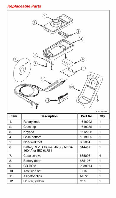
Replaceable Parts . . .
1
2
3
4
5
6
8
7
10
11
12
9
ADA10F.EPS
Item Description Part No. Qty.
1. Rotary knob 1618022 1
2. Case top 1618355 1
3. Keypad 1612222 1
4. Case bottom 1618005 1
5. Non-skid foot 885884 1
6. Battery. 9 V, Alkaline, ANSI / NEDA 1604A or IEC 6LR61
614487 1
7. Case screws 665098 4
8. Battery door 665106 1
9. CD ROM 2088974 1
10. Test lead set TL75 1
11. Alligator clips AC72 1
12. Holster, yellow C10 1

English Instruction SheetPanel 15
Accuracy Specifications Accuracy is specified for 1 year after calibration at operating temperatures of 18 °C to +28 °C and is given as:
±( [ % of reading ]+[ counts ] ) MEASURE V dc
Range: +28 V (+30 V max) Resolution: 1 mV Input Impedance: 1 MΩ Accuracy: ±(0.015 % of reading+2 counts)
MEASURE mA dc Range: 20 mA (24 mA max) Resolution: 1 μA Accuracy: ±(0.015 % of reading+2 counts)
SOURCE / SIMULATE mA dc Range: 0 mA to 20 mA (24 mA max) Resolution: 1 μA Accuracy: ±(0.015 % of reading+2 counts)
Source mode: Compliance: To 1200 Ω at 20 mA
To 950 Ω at 20 mA in HARTTM Mode
Simulate mode: External loop voltage requirement: 24 V nominal, 30 V maximum, 12 V minimum
Loop Power ≥24 V
Percent display -25 % to 125 %
Input / Output Protection Fuseless protection

English Instruction SheetPanel 16
General Specifications Maximum voltage between any terminal and earth ground or between any two terminals:
30 V Storage temperature:
-40 °C to 60 °C Operating temperature:
-10 °C to 55 °C Operating altitude:
3000 meters maximum Temperature coefficient:
±0.005 % of range per °C for temperatures of -10 °C to 18 °C and 28 °C to 55 °C
Relative humidity: 95 % up to 30 °C; 75 % up to 40 °C 45 % up to 50 °C and 35 % up to 55 °C
Vibration: Random 2 g, 5 to 500 Hz
Shock: 1 meter drop test
Safety Compliance: Complies with IEC 61010-1-95 CAT I, 30 V; CSA C22.2 No. 1010-992 NRTL; ANSI/ISA S82.02.01-1994.
CE: Complies with EN61010-1 and EN61326
Power requirements: Single 9 V battery (ANSI/NEDA 1604A or IEC 6LR61)
Battery life (typical): SOURCE mode: 18 hours; 12 mA into 500 Ω; MEASURE / SIMULATE mode: 50 hours
Size: 69.85 mm (W) x 142.87 mm (L) x 50.80 mm (H) [ 2.75 in (W) x 5.625 in (L) x 2.00 in (H) ] With holster and Flex-Stand: 76.20 mm (W) x 158.75 mm (L) x 54.61mm (H) [ 3.00 in (W) x 6.25 in (L) x 2.15 in (H) ]
Weight: 224 g (8 oz); With holster and Stand: 349 g (12.3 oz)
Protection Class: Pollution Degree II