fully enclosed multi-axis inertial reaction...
TRANSCRIPT

Available online at www.sciencedirect.com
Journal of Ocean Engineering and Science 2 (2017) 5–17 www.elsevier.com/locate/joes
Original Article
Fully enclosed multi-axis inertial reaction mechanisms for wave energy
conversion
I.A. Antoniadis, V. Georgoutsos, A. Paradeisiotis
∗
Mechanical Design and Control Systems Section, Mechanical Engineering Department, National Technical University of Athens, Heroon Polytechniou 9, Zografou 15780, Greece
Received 9 October 2016; received in revised form 5 February 2017; accepted 9 February 2017 Available online 22 February 2017
Abstract
This paper introduces a novel concept for wave energy conversion, using fully enclosed appropriate internal body configurations, which provide inertial reaction against the motion of an external vessel. In this way, reliability, robustness and survivability under extreme weather conditions – a fundamental prerequisite for wave energy converters – can be achieved. Acting under the excitation of the waves, the external vessel is subjected to a simultaneous surge and pitch motion in all directions, ensuring maximum wave energy capture in comparison to other wave energy converters like point heave absorbers. The internal body is suspended from the external vessel body in such an appropriate geometrical configuration, that a symmetric four-bar mechanism is essentially formed. The main advantage of this suspension geometry is that a linear trajectory results for the centre of the mass of the suspended body with respect to the external vessel, enabling the introduction of a quite simple form of a Power Take Off (PTO) design. Thus, because of this simplicity and symmetry of the suspension geometry and of the PTO mechanism, the fundamental restrictions of other linear, pendulum or gyroscopic variants on inertial reacting bodies are significantly removed. © 2017 Shanghai Jiaotong University. Published by Elsevier B.V. This is an open access article under the CC BY-NC-ND license. ( http://creativecommons.org/licenses/by-nc-nd/4.0/ )
Keywords: Waves; Energy; Inertial; Pendulum; Platforms; Offshore.
1
w
t
t
c
i
i
w
w
d
s
i
T
T
c
t
t
t
f
i
v
f
v
w
o
w
T
p
r
h2(
. Introduction
Oceans constitute more than 75% of our planet and theaves being produced in them consist one of the biggest un-
apped renewable energy resources of our world. Various es-imates and methodologies with varying figures exist [1–3] ,onverging however to estimates for a wave power exceed-ng 2 TW, which is of the same order as global electric-ty production. Much higher perspectives exist in the hybridind-wave energy exploitation. Using only North Sea sitesith water over 50 m deep as an example, the energy pro-uced in this area could meet today’s EU electricity con-umption four times over [4,5] . An additional potential ex-sts in suitable areas of the Atlantic and Mediterranean seas.his fact has inspired numerous inventors, as early as 1799.he main systematic research effort for efficient wave energy
∗ Corresponding author. E-mail address: [email protected] (A. Paradeisiotis).
d
A
e
ttp://dx.doi.org/10.1016/j.joes.2017.02.003 468-0133/© 2017 Shanghai Jiaotong University. Published by Elsevier B.V. This http://creativecommons.org/licenses/by-nc-nd/4.0/ )
onverters was only stimulated by the emerging oil crisis ofhe 1970s. As a result, more than a thousand of patents andens (if not hundreds) of experimental prototypes are beingested in the sea. Some comprehensive recent reviews can beound in [6–8] . However, contrary to the case of the Hor-zontal Axis Wind Turbine (HAWT) for wind energy con-ersion, no specific technological paradigm exists till todayor efficient wave energy conversion. As a result, numerousarieties of wave energy converters exist, such as oscillatingater columns, attenuators, and point absorbers in the formf heaving buoys, overtopping devices, and oscillating flapave devices being among the most common. However, theirechnological Readiness Levels (TRLs) and overall efficienterformance is still quite low.
One reason is the very short past of 40 years of systematicesearch for wave energy conversion, compared to the hun-reds (if not thousands) of years of wind energy technology.nother reason are the difficulties in understanding the wave
nergy absorption process, involving complex hydrodynamic
is an open access article under the CC BY-NC-ND license.
6 I.A. Antoniadis et al. / Journal of Ocean Engineering and Science 2 (2017) 5–17
e
a
i
a
t
a
f
w
b
a
s
e
s
o
b
t
t
t
i
d
t
s
h
c
b
f
c
t
i
s
m
T
t
a
c
o
b
l
t
b
e
r
e
a
s
i
t
t
m
a
i
phenomena, such as wave diffraction and radiation, althoughsignificant progress has been achieved the last 40 years to-wards this direction.
Today, the main obstacles for efficient wave energy con-version are mainly related to the requirement for survivabilityin extreme weather conditions, and to the energy efficient andreliable design of the PTO mechanism. This last requirementinvolves not so much the design of the PTO device itself, butmuch more its seamless and energy efficient interface and in-tegration with the wave absorption vessel and the electricalgrid.
Towards the last direction, numerous concepts of wave en-ergy converter systems have been conceived, consisting fromtwo-body configurations, in which only one body is in con-tact with the water and the other body is located above thewater or is totally enclosed inside the wetted one. This designenables such mechanisms to fulfil in the best possible way afundamental prerequisite for wave energy converters: the re-quirement for reliability, robustness and survivability underextreme weather conditions.
The earliest example in this direction are perhaps the Frogand PS Frog designs at the University of Lancaster in Eng-land [9,10] . Frog actually refers to a heaving absorber, whilePS Frog refers to a combined surging and pitching absorber,all actually resulting to a PTO mechanism in the form of alinear sliding mass, enclosed inside a floating vessel. Paral-lel, an approach for the theoretical modelling and control ofsuch devices has been performed in [11,12] , essentially forthe heaving ones. An interesting variant of this design, actingessentially in the form of a vertical pendulum has been pro-posed: the SEAREV [13] concept. The basic disadvantagesof these two designs consist in their limited capability forwave capture in a single axis and in the big masses they re-quire for efficient energy capture, thus demanding complexand unreliable support structures.
Other designs in the forms of an inverted pendulum havebeen proposed [14] , which however result to unstable struc-tures, possibly extended quite high above the sea level. Paral-lel, horizontal pendulum designs [15,16] have been proposed,which however introduce problems of stability of the externalvessel, only partially compensated by asymmetric ballast de-signs. Quite recently, the GAIA multi-axis wave energy con-verter has been also proposed [17] . However, it still requiresa complicated support structure and PTO mechanisms.
An interesting variant of such concepts is the class of de-signs, which make use of a gyroscope as an internal reactinginertial configuration [18–22] . However, no systematic anal-ysis exists on the requirements for significant energy captureby such designs, in terms of rotating masses and correspond-ing speeds. Furthermore, their complexity consists a furtherserious disadvantage for their reliability and robustness in theharsh sea environments.
This paper introduces a novel concept for the design of ageneral class of fully enclosed internal body configurations,providing inertial reaction against the motion of an externalvessel, able to drastically overcome the disadvantages of theabove designs. Acting under the excitation of the waves, the
xternal vessel can perform in general a 6 degrees of freedomrbitrary translation and rotation of in space.
The internal bodies are suspended from the external bodyn such appropriate geometrical configurations, that the entiressembly of the internal and external bodies, together withheir suspension systems, form essentially a multi-link mech-nism. The kinematic design of these mechanisms can be per-ormed in such a way, that the internal bodies can follow aell prescribed relative motion with respect to the externalody. Moreover, each individual body has an optimal massnd inertia distribution.
This overall design enables the maximum conversion andtorage of wave energy from all the degrees of freedom of thexternal body, into the form of kinetic and potential energy,tored into the total assembly of the internal bodies. More-ver, since specific points of the internal body assembly cane arranged to follow prescribed trajectories with respect tohe external vessel, simple and established forms of powerake off systems can be appropriately inserted (linear or ro-ary, hydraulic or electrical), in order to further convert thenternally stored mechanical energy to electrical energy.
An example of such an arrangement is further analysed inetails in the rest of this paper. An external vessel is subjectedo simultaneous surge and pitch motion in all directions, en-uring thus maximum wave capture, in comparison for e.g. toeave only point absorbers. An inertial reacting body is en-losed internally, suspended appropriately from the externalody in such a way that a symmetric four-bar mechanism isormed.
The first advantage of this suspension geometry is that theentre of the mass of the suspended body moves in a linearrajectory with respect to the external vessel. This implies thenternal body appears to move essentially in linear way, like aimple mass in the conventional form of the PSFrog arrange-ents. This enables the introduction of a quite simple Powerake Off (PTO) system, as for e.g. hydraulic rams. Moreover,
he simplicity and the symmetry of the suspension geometrynd of the PTO, ensure a quite simple and robust technologi-al implementation, contrary to all other known above variantsf inertial reacting internal bodies.
The second advantage of this design is that the internalody behaves dynamically as a vertically suspended pendu-um. However, the suspension geometry, in combination tohe optimal mass and the inertia distribution of the internalody, ensure the maximal conversion and storage of the wavenergy in the form of kinetic and potential energy. This iseflected to the resulting equivalent pendulum length and in-rtia of this design, which can far exceed those that can bechieved by an actual technical implementation either of aimple horizontal or of a vertical pendulum (suspended, ornverted). The direct consequence is significant reduction ofhe suspended mass.
The kinematic relations and the dynamic equations of mo-ion are derived in Section 2 . In Section 3 the equations ofotion are linearised, an appropriate feedback law is proposed
nd the power that can be converted is estimated. Finally anndicative design is presented in Section 4 , as a standalone
I.A. Antoniadis et al. / Journal of Ocean Engineering and Science 2 (2017) 5–17 7
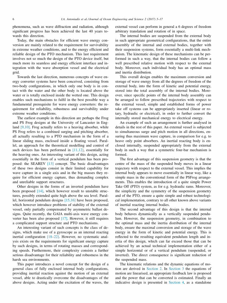
Fig. 1. Schematic presentation of the assembly considered. An internally reacting body S is suspended by an appropriate mechanism from an external floating vessel V .
7
o
f
t
2
2
i
f
t
a
t
i
s
i
o
n
T
e
t
o
s
T
t
o
a
50 kW rated power configuration. In Section 5 , the stand-ut features of this novel design along with the conclusionsrom the dynamical analysis and the indicative implementa-ion are summarised.
. Equations of motion
.1. Description of the assembly and basic definitions
The assembly considered, is depicted in Fig. 1 , consist-ng from a floating external vessel V , into which an internalour-bar mechanism ABDE is hoisted. The waves induce tohe vessel, a simultaneous surge motion of magnitude u and pitching motion of an angle θ , with respect to the iner-ial coordinate system OXY . The origin O is located at the
ntersection of the level of the sea with the vertical axis ofymmetry of the vessel. The centre of mass of the vessel Gs located at a distance b from the point O below the levelf the sea. The member DE of the internal four-bar mecha-ism provides a basis onto which a solid body S is placed.he solid body provides a reaction mass to the motion of thexternal vessel, rotating with an angle φ about the Z axis ofhe inertial reference frame OXY . The initial (rest) position Rf this solid body’s centre of mass, is located on the axis ofymmetry of the vessel V , at a distance a from the origin O .he coordinate reference system RX b Y b is rigidly attached to
he vessel V , following its motion. The form of the mooring system is outside of the scope
f this paper, however it is assumed that the mooring forcesre sufficient to keep the device on station, but negligible
8 I.A. Antoniadis et al. / Journal of Ocean Engineering and Science 2 (2017) 5–17
w
x
y
T
E
r
x
y
w
l
l
r
r
a
(
2
a
T
w
U
w
t
t
t
c
p
t
g
p
in comparison with the wave and dynamic forces. The powertake off mechanism (e.g. hydraulic rams) is quite simple, so itcan be designed to lock – even in a pure mechanical way – theinternal oscillating body in a safe position in the case of roughsea conditions. The rest position of the system correspondsto θ = φ = u = 0
• O : origin of the inertial coordinate system OXY – inter-section of the level of the sea with the vertical axis ofsymmetry of the vessel in the rest position,
• C : centre of mass of the body S , • R : origin of the body axis system RX b Y b – initial (rest)
position of C , • G : centre of mass of the vessel V , • a : distance between R and O , • b : distance between G and O , • φ: rotating angle of the body S about the Z axis, • θ : pitching motion induced by the waves, • u : surge motion induced by the waves.
2.2. Kinematic analysis
The detailed kinematic analysis of the motion of the centreof mass C of the body S with respect to the body fixed frameRX b Y b is performed in Appendix 1 . Also, Fig. 10 shows thegeometrical parameters and kinematic variables of the fourbar mechanism. The symbols are defined as:
• x G
, y G
: coordinates of the centre of gravity G of the ex-ternal vessel, with respect to the inertial coordinate systemOXY ,
• x B , y B : coordinates of the centre of gravity C of the sus-pended mass, with respect to the body fixed coordinatesystem RX b Y b ,
• x M
, y M
: coordinates of the centre of gravity C of the sus-pended mass, with respect to the inertial coordinate systemOXY .
The displacement and velocity of the point G with respectto the inertial coordinate system OXY are as follows:
x G
= u + b sin θ [ m ] (1)
y G
= −b cos θ [ m ] (2)
˙ x G
= ˙ u +
˙ θb cos θ [ m/s ] (3)
˙ y G
=
˙ θb sin θ [ m/s ] (4)
The translation of the reaction mass according to the systemOXY is as follows:
x M
= x R + x B cos θ − y B sin θ
= u + x B cos θ − (a + y B ) sin θ [ m ] (5)
y M
= y R + x B sin θ + y B cos θ
= x B sin θ + (a + y B ) cos θ [ m ] (6)
here:
R = u − a sin θ [ m ] (7)
R = a cos θ [ m ] (8)
he corresponding expressions for x B , y B are given inqs. (A.35) and (A.36) .
The expression of the corresponding velocities ˙ x M
and ˙ y M
esult as follows:
˙ M
= ˙ u − l x M ˙ θ + r x M ˙ φ [ m/s ] (9)
˙ M
= l y M ˙ θ + r y M ˙ φ [ m/s ] (10)
here:
x M = (a + y B ) cos θ + x B sin θ [ m ] (11)
y M = x B cos θ − (a + y B ) sin θ [ m ] (12)
x M = r x cos θ − r y sin θ [ m ] (13)
y M = r x sin θ + r y cos θ [ m ] (14)
nd the expressions for ˙ x B , ˙ y B are given in Eqs. (A.42) andA.43) .
.3. Dynamic equations of motion
The kinetic energy captured from the bodies can be writtens:
=
1
2
m V ( x 2 G
+ ˙ y 2 G
) +
1
2
I V ˙ θ2 +
1
2
m s ( x 2 M
+ ˙ y 2 M
)
+
1
2
I s ( θ − ˙ φ) 2 [
kg m
2
s 2 = J
](15)
here:
• m v : the mass of the vessel V including the added mass ofthe water,
• m s : the mass of the body S , • I V : the moment of inertia of the vessel about O , • I s : the moment of inertia of the reaction mass about C .
The potential energy is as follows:
= m s gy M
+
1
2
K V θ2 + m V gy G
[kg m
2
s 2 = J
](16)
here K V is the hydrostatic stiffness in pitch (and/or roll) forhe vessel about point O , associated with the component ofhe buoyancy force. The gravitational effect of the vessel isaken into consideration separately.
The device is designed as a surge but not heave energyonverter. This implies that it can convert only surge anditch motions of the external vessel. The heave motion ofhe internal device is prohibited due to its weight, which willenerate significant technical problems. Therefore the systemresents three degrees of freedom:
r 1 = u [ m ] , r 2 = θ [ rad ] , r 3 = φ [ rad ] (17)
I.A. Antoniadis et al. / Journal of Ocean Engineering and Science 2 (2017) 5–17 9
T
a
L
w
s
t
w
P⎧⎨⎩w
M
M
M
M
M
M
T
T
T
T
T
t
a
t
t
e
M
s
f
m
f
c
2
e
z
z
w
z
z
f
2
t
t
s
I
z[
3
3
r
r
c
s
w
c
s
T
t
he equations of motion of the system can be derived by thepplication of the following Lagrange principle:
d
dt
( ∂L
∂ r i
)− ∂L
∂ r i = F i , i = 1 , 2, 3 (18)
= T − U (19)
here F i denotes the external and the damping forces of theystem. Using the expressions of derivatives of Appendix A.2 ,he equations of motion result as:
d
dt P u + R u u = F w
[kg m
s 2 = N
](20)
d
dt P θ + K v θ + T vθ + T gθ = 0 [ Nm ] (21)
d
dt P φ + T gφ = T p [ Nm ] (22)
here the generalised momentum values P u [ kg m/s ] , θ [ kg m
2 / s ] , P φ [ kg m
2 / s ] are defined as follows:
P u
P θ
P φ
⎫ ⎬
⎭
=
⎡
⎣
M uu M uθ M uφ
M uθ M θθ M θφ
M uφ M θφ M φφ
⎤
⎦
⎧ ⎨
⎩
˙ u
˙ θ˙ φ
⎫ ⎬
⎭
(23)
ith the components of the mass matrix M :
uu = m v + m s [ kg ] (24)
uθ = m v b cos θ − m s l x M [ kg m ] (25)
uφ = m s r x M [ kg m ] (26)
θθ = I v + I s + m v b
2 + m s (l 2 x M + l 2 y M ) [ kg m
2 ] (27)
θφ = −[I s + m s (r x M l x M − r y M l y M )
][ kg m
2 ] (28)
φφ = I s + m s (r 2 x M + r 2 y M ) [ kg m
2 ] (29)
he moments due to the gravity are:
vθ = m v gb sin θ [ Nm ] (30)
gθ = m s gl y M [ Nm ] (31)
gφ = m s gr y M [ Nm ] (32)
he rest of the terms are:
• R u : an added damping coefficient for the surge motion in-duced by the waves (radiation force),
• F w
: the force due to the incident and diffracted waves, • T p : the reaction moment of the PTO mechanism, propor-
tionate to the angular velocity of the oscillating internalbody
˙ φ.
The water-plane area is taken to be small compared withhe frontal area, so that excitation moments in pitch are rel-tively small, therefore not participating in the model deriva-ion. The part of the radiation force describing the effect ofhe added mass is incorporated in the expression of the gen-ralised momentum P u and the added mass is represented as uu in the mass matrix Eq. (23) . The design concept is quite
imple, since it foresees that the internal body is suspendedrom the external body by ropes or equivalent mooring lineaterials. Therefore, at this preliminary stage, the effects of
rictional damping generated from the various connections areonsidered negligible.
.4. State space representation
A compact state space representation for the system ofquations is possible under the following compact form:
˙ 1 = M
−1 z 2 (33)
˙ 2 = f R (34)
here:
T 1 = r T =
{u θ φ
}(35)
T 2 =
{P u P θ P φ
}(36)
R =
⎧ ⎨
⎩
F w
− R u u
−K vθ − T vθ − T gθ−T gφ + T p
⎫ ⎬
⎭
(37)
.5. Equation of motion of the internal inertial reacting body
Under the assumption that the surge and pitch motion ofhe external vessel are known in the time domain, the equa-ions of motion can be further simplified, retaining only theet of equations which refer to the mechanism itself:
d
dt (M φφ
˙ φ) = − d
dt (M uφ ˙ u + M θφ
˙ θ ) − T gφ + T p [ Nm ] (38)
n an equivalent state space representation:
=
[φ
P φ
](39)
˙ φ˙ P φ
]=
[(P φ − M uφ ˙ u − M φφ
˙ φ) /M φφ
−T gφ + T p
](40)
. Maximum power conversion capability
.1. Linearisation of the equations of motion
Under the assumption of small perturbations around theest position of the mechanism, the following approximateelations hold for the angles α ∈ { φ, ψ , θ} of the assembly:
os α ≈ 1 (41)
in α ≈ α (42)
hich results to:
os γ = cos (γ0 − ψ) ≈ cos γ0 + ψ sin γ0 (43)
in γ = sin (γ0 − ψ) ≈ sin γ0 − ψ cos γ0 (44)
he equations of motion (A.35) and (A.36) of the of the cen-re of mass C of the oscillating body with respect to the origin

10 I.A. Antoniadis et al. / Journal of Ocean Engineering and Science 2 (2017) 5–17
w
p
f
T
w
i
I
O
3
f
p
i
i
l
h
r
i
c
c
o
p
c
3
p
t
t
e
p
a
p
θ
w
f
u
A
I
R of the coordinate system RX b Y b can thus be simplified asfollows:
x B ≈ l p φ [ m ] (45)
y B ≈ 0 [ m ] (46)
l p = (μ + 1) h [ m ] (47)
μ ≈ μ0 =
2c
lσ0 =
c
l cos γ0 =
1
d/c − 1
(48)
σ ≈ σ0 =
sin 2γ0
sinγ0 = 2 cos γ0 (49)
Eq. (46) implies that the physical motion of the centreof the mass of the body is linear, exactly in the same wayas the traditional designs of linear sliding mass Wave EnergyConverters (WECs), as for e.g. in the form of PS Frog. Similarsimplified relations hold for the e factors r x , r y , l x M , l y M , r x M and ry M
:
r x ≈ l p [ m ] (50)
r y ≈ 0 [ m ] (51)
l x M ≈ a [ m ] (52)
l y M ≈ l p φ [ m ] (53)
r x M ≈ l p [ m ] (54)
r y M ≈ l p θ [ m ] (55)
as well as for the components of the matrix M :
M =
⎡
⎣
m v m v b m s l p m v b I v + I s + m v b
2 −I θm s l p −I θ I φ
⎤
⎦ (56)
and the moments due to the gravity:
I θ = I s + m s l p a [ kg m
2 ] (57)
I φ = I s + m s l 2 p [ kg m
2 ] (58)
T vθ ≈ 0 [ Nm ] (59)
T gθ ≈ m s gl p φ [ Nm ] (60)
T gφ ≈ m s gl p θ [ Nm ] (61)
3.2. Proposed form for the power take off moment and
feedback law
In view of the non-linear equation of motion (38) , themechanism is inherent to an unstable behaviour. For this rea-son, a feedback law is incorporated in the power take offmoment to ensure static and dynamic stability, being of thefollowing form:
T p = −K p φ − R p φ + T N [ Nm ] (62)
here K p and R p are constant linear feedback gains to beroperly selected and T N
denotes an appropriate compensatoror the non-linearity of the system in the form:
N =
d
dt (P φ − m s l p u + I θ ˙ θ − I φ ˙ φ) + (T gφ − m s gl p θ ) [ Nm ]
(63)
hich results to the following equation for motion of thenternal body:
φφ + R p φ + K p φ = −m s l p u + I θ θ − m s gl p θ + T N [ Nm ]
(64)
bviously T N
is equal to zero for a linearised system.
.3. Analysis of the expected dynamic behaviour
Eq. (64) implies that the motion of the internal body isully equivalent dynamically to that of a damped physicalendulum, with a mass m s and inertia I s about its CM , whichs suspended at a distance l p from its centre of mass. However,t should be stretched, that in view of Eq. (47) , the equivalentength l p of this pendulum can be many orders of magnitudeigher than that expected by any other vertical pendulum,ealised in the traditional natural technological way, as for e.g.n the form of SEAREV. This pendulum can simultaneouslyonvert three different forms of wave energy:
• The kinetic energy resulting from the surge motion. • The kinetic energy resulting from the pitching motion. • The potential energy resulting from the pitching motion.
In view of Eq. (62) , the selection of the feedback gainsan be performed in a way to ensure stability of the system,ptimal tuning of the natural periods of the system to theeriods of the external source, as well as maximum poweronversion capability.
.4. Calculation of maximum power conversion capacity
The analysis of the power conversion capability can beerformed independently for the surge and pitch motion ofhe converter. However, the design of the external vessel andhe coupled form of equations [14] imply that a dependencexists in fact between them. Detailed analysis of such a de-endence is performed in [14] . Following the outline of suchn analysis, the vessel will be assumed to be subjected to aitching motion of amplitude C
and frequency ω.
(t ) = C cos (ωt ) [ rad ] (65)
hile the surge motion will depend on the pitch motion asollows:
(t ) = −bθ (t ) = −bC cos (ωt ) [ m ] (66)
s a result, the equation of motion (64) now becomes:
φφ + R p φ + K p φ = −M e C cos (ωt ) (67)
I.A. Antoniadis et al. / Journal of Ocean Engineering and Science 2 (2017) 5–17 11
w
T
M
I
T
w
π
c
φ
T
g
s
t
v
E
R
K
T
P
w
T
S
e
P
o
P
w
X
α
l
a
t
t
p
T
c
s
d
t
e
4
l
T
2
m
d
c
r
s
s
w
[
1
w
a
W
s
R
b
w
o
c
t
7
o
w
t
c
a
f
h
fi
a
t
a
d
t
t
w
o
fi
here
p = −K p φ − R p φ [ Nm ] (68)
e = ω
2 I P + m s gl p
[kg
(m
s
)2 ]
(69)
P = I S + m s l p (a + b) [ kg m
2 ] (70)
he steady state response of the system is a harmonic functionith a frequency equal to ω and with a phase difference of/2 with the excitation force, in order to maximise power
apture from the excitation force:
(t ) = −�S sin (ωt ) [ rad ] (71)
he minus sign is used to denote that for the positive θ an-le, a negative φ angle should result, in order to ensure thetability of the vessel, meaning that the internal configura-ion oscillates with a π /2 phase difference with the externalessel, thus, avoiding collision or overturning. Substitution ofqs. (58) and (69) into Eq. (67) leads to the following results:
p =
M e c
ω�s
[kg
m
2
s
](72)
p = ω
2 I φ
[kg
(m
s
)2 ]
(73)
he mean power absorbed by the PTO is defined as follows:
out =
1
T w
∫ T w
0 T p φdt [ W ] (74)
here the wave period is
w
=
2π
ω
[ s ] (75)
ubstitution of Eqs. (68) , (75) into (74) leads to the followingxpression
out = −1
2
ωM e c �s = −P in [ W ] (76)
r alternatively to:
out = −1
2
ωc m s X M
αe [ W ] (77)
here:
M
= l p �s [ m ] (78)
e = g + ω
2 (a + b + l I ) [ m
s 2
] (79)
I =
I S m s l p
[ m ] (80)
nd
• X M
: amplitude of the linear motion of the centre of massof the oscillating body,
• �s : maximum inclination of the mechanism, • I S : inertia of the oscillating body about its CM , • T : sea waves period.
wIn summary, the inclusion of the PTO mechanism withhe incorporated feedback law, allows the designer to limithe amplitude of the internal body’s angle, by controlling ap-ropriately the damping coefficient of the PTO mechanism.his means that as far as the movement of the internal body isoncerned, which is simulated and presented in this paper, theelection of a comparably big excitation pitch amplitude C
,oes not violate the assumption of small perturbations used inhe linearisation of the equation nor it inserts any significantrror between the linearised and the non-linear model.
. A standalone 750 kW rated power configuration
The wave energy level is expressed as power per unitength along the wave crest or along the shoreline direction.ypical values for “good” offshore locations range between0 and 70 [ kW/m ] as annual average and occur mostly inoderate to high latitudes, as for e.g. in the North Sea. A
esign approach for a peak energy level of 30 [ kW/m ] (alsoonsidering good locations in the Mediterranean Sea) can beeasonably used as a target value to be reached by the sub-equent configurations to be designed.
The actual power that can be absorbed by a pitching andurging WEC is expressed by the value of the Capture Width,hich is around L = λ/π [ m ] , for pitching and surging WECs
7] . Assuming a typical value for the wavelength of λ ≈ 50 :00 [ m ] , L is calculated. Multiplication of this value with theave power per unit length, results to a total value of power
round 0. 5 : 1 MW [14] , which can be absorbed by a uniqueEC. Moreover, assuming the buoy to be of a hemispherical
hape, estimates for the optimum radius of the buoy D v / 2 = = 0. 262T 2 w
[ m ] can be derived [7] , although this value haseen proved for heaving motion only. Taking into accountave periods of 6: 10 s, this leads to buoy with a radiusf at least 10 : 14 [ m ] , able to capture the amount of poweralculated previously. The above estimates are in line withhe results found in corresponding sources [23] .
Therefore, an indicative mechanism for a standalone50 [ kW ] rated configuration is presented. A body consistingf two unequal spheres and a beam that links them togetherill be used as an inertial mass. This body is suspended with
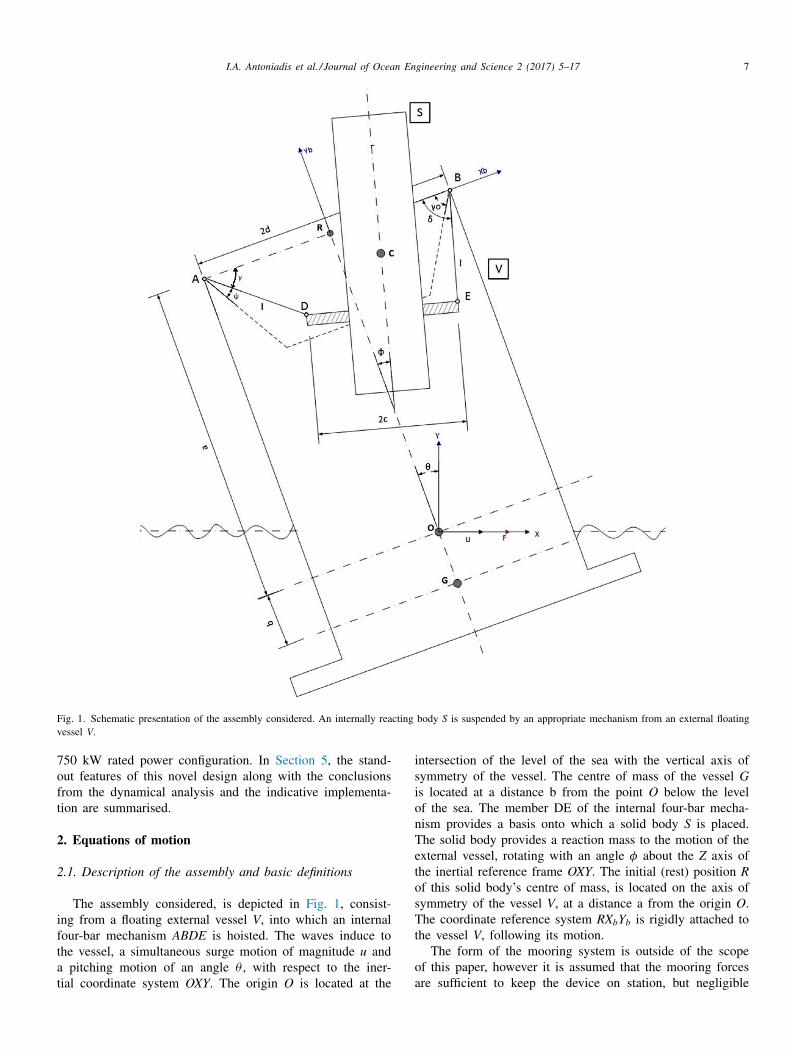
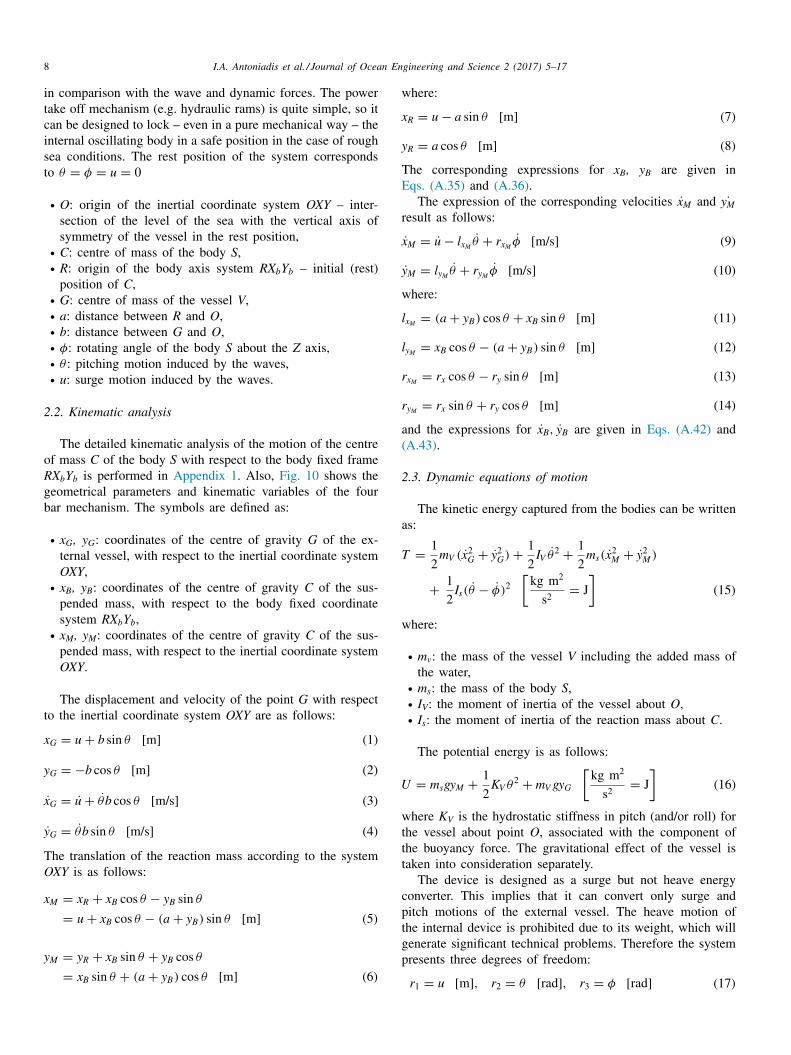
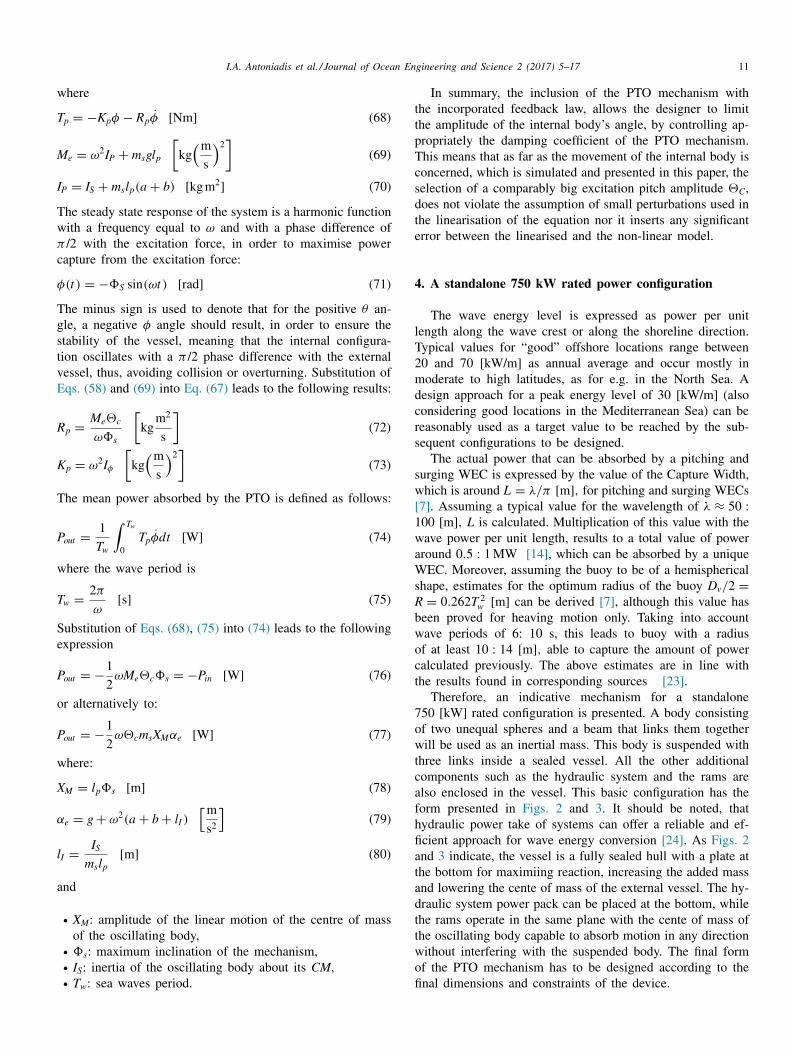
hree links inside a sealed vessel. All the other additionalomponents such as the hydraulic system and the rams arelso enclosed in the vessel. This basic configuration has theorm presented in Figs. 2 and 3 . It should be noted, thatydraulic power take of systems can offer a reliable and ef-cient approach for wave energy conversion [24] . As Figs. 2nd 3 indicate, the vessel is a fully sealed hull with a plate athe bottom for maximiing reaction, increasing the added massnd lowering the cente of mass of the external vessel. The hy-raulic system power pack can be placed at the bottom, whilehe rams operate in the same plane with the cente of mass ofhe oscillating body capable to absorb motion in any directionithout interfering with the suspended body. The final formf the PTO mechanism has to be designed according to thenal dimensions and constraints of the device.
12 I.A. Antoniadis et al. / Journal of Ocean Engineering and Science 2 (2017) 5–17
Fig. 2. A fully enclosed multi-axis combined surge and pitch configuration, for wave energy conversion.
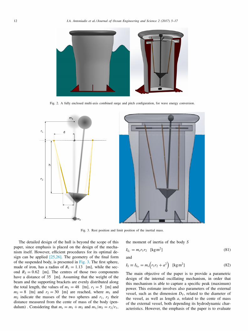
Fig. 3. Rest position and limit position of the inertial mass.
t
I
a
I
T
d
t
p
v
t
o
The detailed design of the hull is beyond the scope of thispaper, since emphasis is placed on the design of the mecha-nism itself. However, efficient procedures for its optimal de-sign can be applied [25,26] . The geometry of the final formof the suspended body, is presented in Fig. 3 . The first sphere,made of iron, has a radius of R 1 = 1 . 13 [ m ] , while the sec-ond R 2 = 0. 62 [ m ] . The centres of those two componentshave a distance of 35 [ m ] . Assuming that the weight of thebeam and the supporting brackets are evenly distributed alongthe total length, the values of m 1 = 48 [ tn ] , r 1 = 5 [ m ] andm 2 = 8 [ tn ] and r 2 = 30 [ m ] are reached, where m 1 andm 2 indicate the masses of the two spheres and r 1 , r 2 theirdistance measured from the cente of mass of the body (pen-dulum) . Considering that m s = m 1 + m 2 and m 1 /m 2 = r 2 /r 1 ,
ahe moment of inertia of the body S
S C = m s r 1 r 2 [ kg m
2 ] (81)
nd
S ≡ I S O = m s
(r 1 r 2 + a
2 )
[ kg m
2 ] (82)
he main objective of the paper is to provide a parametricesign of the internal oscillating mechanism, in order thathis mechanism is able to capture a specific peak (maximum)ower. This estimate involves also parameters of the externalessel, such as the dimension D V , related to the diameter ofhe vessel, as well as length a , related to the cente of massf the external vessel, both depending its hydrodynamic char-cteristics. However, the emphasis of the paper is to evaluate
I.A. Antoniadis et al. / Journal of Ocean Engineering and Science 2 (2017) 5–17 13
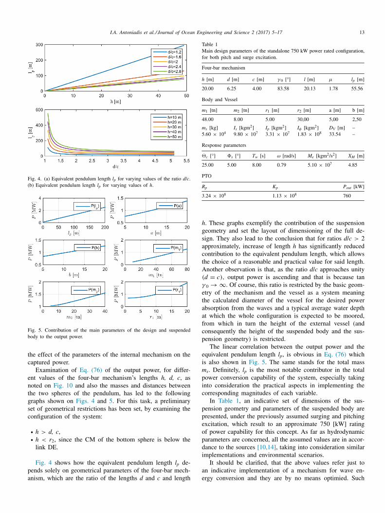
Fig. 4. (a) Equivalent pendulum length l p for varying values of the ratio d / c . (b) Equivalent pendulum length l p for varying values of h .
Fig. 5. Contribution of the main parameters of the design and suspended body to the output power.
t
c
e
n
t
g
s
c
p
a
Table 1 Main design parameters of the standalone 750 kW power rated configuration, for both pitch and surge excitation.
Four-bar mechanism
h [m] d [m] c [m] γ 0 [ °] l [m] μ l p [m]
20.00 6.25 4.00 83.58 20.13 1.78 55.56
Body and Vessel
m 1 [tn] m 2 [tn] r 1 [m] r 2 [m] a [m] b [m]
48.00 8.00 5.00 30,00 5,00 2,50
m s [kg] I s [kgm
2 ] I p [kgm
2 ] I φ [kgm
2 ] D V [m] –5.60 × 10 4 9.80 × 10 7 3.31 × 10 7 1.83 × 10 8 33.54 –
Response parameters
c [ °] �s [ °] T w [s] ω [rad/s] M e [kgm
2 /s 2 ] X M
[m]
25.00 5.00 8.00 0.79 5.10 × 10 7 4.85
PTO
R p K p P out [kW]
3.24 × 10 8 1.13 × 10 8 760
h
g
s
a
c
t
A
γ
e
t
a
a
f
c
p
e
i
m
p
i
c
p
p
e
o
p
d
i
a
e
he effect of the parameters of the internal mechanism on theaptured power.
Examination of Eq. (76) of the output power, for differ-nt values of the four-bar mechanism’s lengths h, d, c , asoted on Fig. 10 and also the masses and distances betweenhe two spheres of the pendulum, has led to the followingraphs shown on Figs. 4 and 5 . For this task, a preliminaryet of geometrical restrictions has been set, by examining theonfiguration of the system:
• h > d, c , • h < r 2 , since the CM of the bottom sphere is below the
link DE.
Fig. 4 shows how the equivalent pendulum length l p de-ends solely on geometrical parameters of the four-bar mech-nism, which are the ratio of the lengths d and c and length
. These graphs exemplify the contribution of the suspensioneometry and set the layout of dimensioning of the full de-ign. They also lead to the conclusion that for ratios d / c > 2pproximately, increase of length h has significantly reducedontribution to the equivalent pendulum length, which allowshe choice of a reasonable and practical value for said length.nother observation is that, as the ratio d / c approaches unity
(d = c) , output power is ascending and that is because tan0 → ∞ . Of course, this ratio is restricted by the basic geom-try of the mechanism and the vessel as a system meaninghe calculated diameter of the vessel for the desired powerbsorption from the waves and a typical average water deptht which the whole configuration is expected to be moored,rom which in turn the height of the external vessel (andonsequently the height of the suspended body and the sus-ension geometry) is restricted.
The linear correlation between the output power and thequivalent pendulum length l p , is obvious in Eq. (76) whichs also shown in Fig. 5 . The same stands for the total mass s . Definitely, l p is the most notable contributor in the totalower conversion capability of the system, especially takingnto consideration the practical aspects in implementing theorresponding magnitudes of each variable.
In Table 1 , an indicative set of dimensions of the sus-ension geometry and parameters of the suspended body areresented, under the previously assumed surging and pitchingxcitation, which result to an approximate 750 [ kW ] ratingf power capability for this concept. As far as hydrodynamicarameters are concerned, all the assumed values are in accor-ance to the sources [10,14] , taking into consideration similarmplementations and environmental scenarios.
It should be clarified, that the above values refer just ton indicative implementation of a mechanism for wave en-rgy conversion and they are by no means optimied. Such
14 I.A. Antoniadis et al. / Journal of Ocean Engineering and Science 2 (2017) 5–17
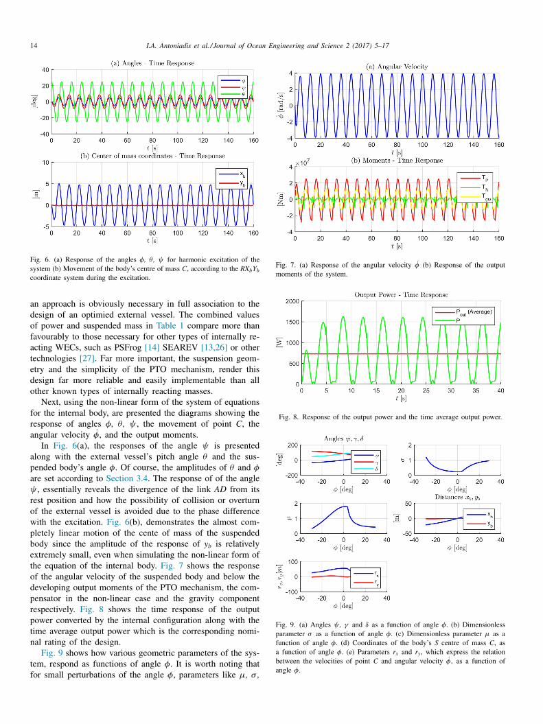
Fig. 6. (a) Response of the angles φ, θ , ψ for harmonic excitation of the system (b) Movement of the body’s centre of mass C , according to the RX b Y b coordinate system during the excitation.
Fig. 7. (a) Response of the angular velocity ˙ φ (b) Response of the output moments of the system.
Fig. 8. Response of the output power and the time average output power.
Fig. 9. (a) Angles ψ , γ and δ as a function of angle φ. (b) Dimensionless parameter σ as a function of angle φ. (c) Dimensionless parameter μ as a function of angle φ. (d) Coordinates of the body’s S centre of mass C , as a function of angle φ. (e) Parameters r x and r y , which express the relation between the velocities of point C and angular velocity ˙ φ, as a function of angle φ.
an approach is obviously necessary in full association to thedesign of an optimied external vessel. The combined valuesof power and suspended mass in Table 1 compare more thanfavourably to those necessary for other types of internally re-acting WECs, such as PSFrog [14] SEAREV [13,26] or othertechnologies [27] . Far more important, the suspension geom-etry and the simplicity of the PTO mechanism, render thisdesign far more reliable and easily implementable than allother known types of internally reacting masses.
Next, using the non-linear form of the system of equationsfor the internal body, are presented the diagrams showing theresponse of angles φ, θ , ψ , the movement of point C , theangular velocity
˙ φ, and the output moments. In Fig. 6 (a), the responses of the angle ψ is presented
along with the external vessel’s pitch angle θ and the sus-pended body’s angle φ. Of course, the amplitudes of θ and φ
are set according to Section 3.4 . The response of of the angleψ , essentially reveals the divergence of the link AD from itsrest position and how the possibility of collision or overturnof the external vessel is avoided due to the phase differencewith the excitation. Fig. 6 (b), demonstrates the almost com-pletely linear motion of the cente of mass of the suspendedbody since the amplitude of the response of y b is relativelyextremely small, even when simulating the non-linear form ofthe equation of the internal body. Fig. 7 shows the responseof the angular velocity of the suspended body and below thedeveloping output moments of the PTO mechanism, the com-pensator in the non-linear case and the gravity componentrespectively. Fig. 8 shows the time response of the outputpower converted by the internal configuration along with thetime average output power which is the corresponding nomi-nal rating of the design.
Fig. 9 shows how various geometric parameters of the sys-tem, respond as functions of angle φ. It is worth noting thatfor small perturbations of the angle φ, parameters like μ, σ ,

I.A. Antoniadis et al. / Journal of Ocean Engineering and Science 2 (2017) 5–17 15
Fig. 10. Geometric parameters and kinematic variables of the four-bar mechanism.
r
w
t
5
c
g
l
f
s
b
P
t
q
o
m
t
r
p
t
i
i
d
t
e
f
i
c
q
c
i
t
d
p
o
c
t
A
A
G
d
.
f
l
t
R
b
T
m
t
b
m
d
b
c
l
l
x , r y and the angles ψ , γ , δ remain approximately constant,hich showcases the validity of the assumption of small per-
urbations during the linearisation of the model.
. Conclusion
This concept of wave energy conversion, using fully en-losed inertially reacting bodies under appropriate suspensioneometry from an external floating vessel, can provide a re-iable and simple design, able to meet the severe conditionsor survivability under extreme weather conditions. As it re-ults, the linear motion of the cente of mass of the suspendedody enables the introduction of a quite simple form of aTO design. Moreover, the simplicity and the symmetry of
he suspension geometry and of the PTO mechanism, ensure auite simple and robust technological implementation. More-ver, the optimal dynamic design of the geometry and theass and the inertia distribution of the internal body ensure
he maximal conversion and storage of the wave energy. Thisesults to a significant reduction of the suspended mass, com-ared to other internal reacting designs. Also, the mass andhe inertia distribution of the internal body is optimied, ensur-ng the maximal conversion and storage of the wave energyn the form of kinetic and potential energy. As a result, theynamic behaviour of the internal body assembly is essen-ially that of an equivalent vertical physical pendulum. How-ver, the resulting equivalent pendulum length and inertia canar exceed those that can be achieved by an actual technicalmplementation either of a simple horizontal or of a verti-al pendulum (suspended, or inverted), with a direct conse-uence to a significant reduction of the suspended mass. Theoncept is flexible and parametrically designed, enabling itsmplementation in any form of floating vessels. A first op-ion is as standalone WECs, fully enclosed in appropriatelyesigned hulls. Moreover, an alternative direction for their im-
lementation consists in properly embedding them in floatingffshore platforms, supporting wind turbines. Such a designan drastically enhance the performance, the efficiency andhe potential of floating offshore energy applications.
ppendix A
1. Kinematic analysis of the four-bar mechanism
eometric parameters The basic geometrical configuration of the mechanism is
efined by the selection of the three independent lengths , , The rest of the geometric parameters can be retrieved asollows:
=
√
(d − c) 2 + h
2 [ m ] (A.1)
an γ0 =
h
d − c (A.2)
eference position of the mechanism
The reference (rest) position of the mechanism, indicatedy dashed lines, is defined by the following relations:
φ = ψ = 0 [ rad] , γ = δ = γ0 [ rad ] (A.3)
he origin of the coordinate system RX b Y b is selected in theiddle of the stationary link (ground) of the mechanism, with
he position of the axes indicated as in the figure. Relationsetween the angles of the mechanism. The kinematics of theechanism can be fully retrieved as a function of a single
egree of freedom: the angle φ. he rest of the angles cane retrieved by the following compatibility relations of thelosed kinematic chain:
cos γ + 2c cos φ + l cos δ = 2d [ m ] (A.4)
sin γ + 2c sin φ − l sin δ = 0 [ m ] (A.5)
16 I.A. Antoniadis et al. / Journal of Ocean Engineering and Science 2 (2017) 5–17
o
l
l
C
l
s
γ
W
f
γ
ψ
μ
σ
M
a
o
t
t
b
x
y
h
I
a
t
v
x
y
o
x
y
a
x
y
w
r
ry
Reforming the above equations, the following system is ob-tained:
l cos δ = 2d − l cos γ − 2c cos φ [ m ] (A.6)
l sin δ = l sin γ + 2c sin φ [ m ] (A.7)
Using the following abbreviations,
x φ = d − c cos φ [ m ] (A.8)
y φ = c sin φ [ m ] (A.9)
r φ = x 2 φ + y 2 φ [ m
2 ] (A.10)
After squaring each of the above equations and adding them:
l 2 = (2x φ − l cos γ ) 2 + (2y φ + l sin γ ) 2 (A.11)
which results to:
−x φ l cos γ + y φ l sin γ + r φ = 0 (A.12)
This equation can be further recast to second order polyno-mial equation
α2φz 2 γ + 2α1 φz γ + α0φ = 0 (A.13)
where
z γ = tan(γ / 2) (A.14)
a 2φ = r φ + x φ l [ m
2 ] (A.15)
a 1 φ = y φ l [ m
2 ] (A.16)
a 0φ = r φ − x φ l [ m
2 ] (A.17)
which can lead to the definition of the angle γ as a functionof the angle φ.
γ = 2 tan
(−a 1 φ + �
a 2 φ
)−1 [ rad ] (A.18)
� =
√
a
2 1 φ − a 2φa 0φ [ m
2 ] (A.19)
The rest of the angles can be then obtained as follows:
ψ = γ0 − γ [ rad ] (A.20)
δ = sin
(sin γ +
2c
l sin φ
)−1 [ rad ] (A.21)
Angular velocities The time derivatives of the compatibility relations of the
closed kinematic chain (A.4) and (A.5) , lead to the followingequations:
−l γ sin γ − 2c φ sin φ − l δ sin δ = 0 (A.22)
l γ cos γ + 2c φ cos φ + l δ cos δ = 0 (A.23)
These can be further processed as following:
l δ sin δ = −l γ sin γ − 2c φ sin φ (A.24)
l δ cos δ = l γ cos γ + 2c φ cos φ (A.25)
r
δ cos δ tan δ = −l γ sin γ − 2c φ sin φ (A.26)
δ cos δ tan δ = (l γ cos γ + 2c φ cos φ) tan δ (A.27)
ombining Eqs. (A.26) and (A.27) together the following re-ations are obtained:
(l γ cos γ + 2c φ cos φ) tan δ = −l γ sin γ − 2c φ sin φ ⇔
(A.28)
in δ(l γ cos γ + 2c φ cos φ) = cos δ(−l γ sin γ − 2c φ sin φ) ⇔(A.29)
˙ lsin(γ + δ) = − ˙ φ2c sin (φ + δ) (A.30)
hich can be finally expressed in the following compactorm:
˙ = − 2c
lσ˙ φ = −μ ˙ φ [ rad/s ] (A.31)
˙ = −˙ γ = μ ˙ φ [ rad/s ] (A.32)
=
2c
lσ(A.33)
=
sin (γ + δ)
sin (φ + δ) (A.34)
otion of the cente of mass The original position of the cente of mass C of a body
ttached to the mechanism is assumed to coincide with therigin R of the coordinate system RX b Y b at the rest position ofhe mechanism. Therefore, its coordinates x B , y B with respecto this system at an arbitrary position of the mechanism cane derived as follows:
B = −d + l cos γ + c cos φ + h sin φ [ m ] (A.35)
B = l sin γ + c sin φ − h cos φ [ m ] (A.36)
= l sin γ0 [ m ] (A.37)
t is easy to derive that y B is equal to zero when l = 2d = 4c,s it is the special case of the Roberts linkage. Therefore,he point moves in a straight line over the segment AB . Theelocities of C can be derived as follows:
˙ B = −l γ sin γ − c φ sin φ + h
φ cos φ [ m/s ] (A.38)
˙ B = l γ cos γ + c φ cos φ + h
φ sin φ [ m/s ] (A.39)
r, in view of Eq. (A.31)
˙ B = (lμ sin γ − c sin φ + h cos φ) φ [ m/s ] (A.40)
˙ B = (−lμ cos γ + c cos φ + h sin φ) φ [ m/s ] (A.41)
nd finally in the following compact form:
˙ B = r x ˙ φ [ m/s ] (A.42)
˙ B = r y ˙ φ [ m/s ] (A.43)
here:
x = lμ sin γ − c sin φ + h cos φ [ m ] (A.44)
= −lμ cos γ + c cos φ + h sin φ [ m ] (A.45)
I.A. Antoniadis et al. / Journal of Ocean Engineering and Science 2 (2017) 5–17 17
A
L
w
t
h
r
r
T
e
T
e
T
E
R
[
[[[
[
[[
[
[
[
[
[
[
[[
[[
[
2. Derivatives of the Lagrangian function
The Lagrangian of the system is defined as follows:
= T − U (A.46)
here the expressions for the kinetic energy and of the po-ential energy are defined in Eqs. (15) and (16) . The systemas three degrees of freedom:
=
{u θ φ
}T (A.47)
˙ =
{ ˙ u
˙ θ ˙ φ}T
(A.48)
he derivatives of the Lagrangian function for the kinetic en-rgy part are:
∂L
∂ u
=
∂T
∂ u
= m v x G
∂ x G
∂ u
+ m v x M
∂ x M
∂ u
= m v x G
+ m s x M
= (m v + m s ) u + (m v b cos θ − m s l x M ) θ + m s r x M ˙ φ (A.49)
∂L
∂ θ=
∂T
∂ θ
= I v θ + I s ( θ − ˙ φ) + m v x G
+ m v y G
∂ y G
∂ θ+ m s x M
∂ x M
∂ θ
+ m s y M
∂ y M
∂ θ
= I v θ + I s ( θ − ˙ φ) + m v ( u + b
θ cos θ ) b cos θ
+ m v b
θ sin θb sin θ
+ m s ( u − l x M ˙ θ + r x M ˙ φ)(−l x M ) + m s (l y M ˙ θ + r y M ˙ φ) l y M = (m v b cos θ − m s l x M ) u + [ I v + I s + m v b
2
+ m s (l 2 x M + l 2 y M )]
θ − [ I s + m s (r x M l x M ) − r y M l y M ] φ
(A.50)
∂L
∂ ˙ φ=
∂T
∂ ˙ φ= I s ( θ − ˙ φ) + m s x M
∂ x M
∂ ˙ φ+ m s y M
∂ y M
∂ ˙ φ
= m s ( u − l x M ˙ θ + r x M ˙ φ) r x M + m s (l y M ˙ θ + r y M ˙ φ) r y M + I s ( θ − ˙ φ)
= m s r x M ˙ u − [ I s + m s (r x M l x M − r y M l y M )] θ
+ [ I s + m s (r 2 x M + r 2 y M )]
φ (A.51)
he derivatives of the Lagrangian function for the potentialnergy part are:
∂L
∂u
=
∂T
∂u
= 0 [ N ] (A.52)
∂L
∂θ=
∂T
∂θ= K v θ + m v gb sin θ + m s gl y M [ Nm ] (A.53)
∂L
∂φ=
∂T
∂φ= m s gr y M [ Nm ] (A.54)
he expressions for l x M , l y M , r x M , r y M are defined in equationsqs. (11) –(14) .
eferences
[1] K. Gunn , C. Stock-Williams , Renew. Energy 44 (2012) 296–304 . [2] D.S. Richardson , G.A. Aggidis , Ocean Renew. Energy 8 (2013) . [3] R. Bedard , G. Hagerman , Offshore Wave Power Feasibility Demonstra-
tion Project: Project Definition Study, Final Summary Report, EPRI,2005 .
[4] A. Athanasia, A.-B. Genachte, Deep Water: The Next Step for OffshoreWind Energy, 2013 URL http://www.ewea.org/ fileadmin/ files/ library/ publications/ reports/ Deep _ Water.pdf.
[5] L. Serri, A. Sempreviva, T.Pontes, J. Murphy, K. Lynch, D. Airoldi,J. Hussey, C. Rudolph, I. Karagali, 2012 . Resource Data andGIS Tool: For Offshore Renewable Energy Projects in Eu-rope, URL http:// www.orecca.eu/ c/ document _ library/ get _ file?uuid=757326c6- 102f- 4dd3- 8790- 916755694103&groupId=10129 .
[6] B. Drew , A. Plummer , M.N. Sahinkaya , Proc. Inst. Mech. Eng. Part AJ. Power Energy 223 (8) (2009) 887–902 .
[7] A.F. de O. Falcão , Renew. Sustain. Energy Rev. 14 (3) (2010) 899–918 .[8] K. Lynch, J. Murphy, 2012 . Deliverable d3.6: Overview of Off-
shore Wind and Ocean Energy Technologies, URL http://www.marina-platform.info/dissemination.aspx.
[9] R. Bracewell , Frog and PS Frog: A Study of two Reactionless OceanWave Energy Converters, Ph.D. thesis, Lancaster University, UK, 1990 .
10] A. McCabe , A. Bradshaw , J. Meadowcroft , G. Aggidis , Renew. Energy31 (2) (2006) 141–151 .
11] U. Korde , Appl. Ocean Res. 21 (5) (1999) 235–248 . 12] U.A. Korde , Appl. Ocean Res. 23 (5) (2001) 251–262 . 13] A. Babarit , A. Clement , J. Gilloteaux , in: Proceedings of the Twen-
ty-fourth International Conference on Offshore Mechanics and ArcticEngineering, Halkidiki, Greece, vol. 2, 2005, pp. 703–712 .
14] M.B. Widden , M.J. French , G.A. Aggidis , Proc. Inst. Mech. Eng. PartM J. Eng. Marit. Environ. 222 (2008) 153–161 .
15] W. Ltd. , The Penguin Wave Energy Converter, 2015 . 16] EERE, Wave energy prize, URL http://waveenergyprize.org/, Online;
accessed Oct-2016. 17] D. Zhang , G. Aggidis , Y. Wang , A. Mccabe , W. Li , Appl. Phys. Lett.
103 (10) (2013) . 18] F. Salcedo , P. Ruiz-Minguela , R. Rodriguez , P. Ricci , M. Santos , in:
Proceedings of the Eighth European Wave Tidal Energy Conference,2009, p. 4605 .
19] T. Perez , M. Santos-Mujica , J.P. Ruiz-Minguela , in: Proceedings of the2009 European Control Conference (ECC), 2009, pp. 3743–3748 .
20] H. Kanki , S. Arii , T. Furusawa , T. Otoyo , in: Proceedings of the EighthEuropean Wave and Tidal Energy Conference, 2009 .
21] G. Waizmann , The Wave Gyro, Master thesis, University of Southamp-ton, UK, 2011 .
22] G. Bracco , E. Giorcelli , G. Mattiazzo , Mech. Mach. Theory 46 (10)(2011) 1411–1424 .
23] A. Babarit , Renew. Energy 80 (2015) 610–628 . 24] J.F. Gaspar , M. Calvrio , M. Kamarlouei , C.G. Soares , Renew. Energy
86 (2016) 1232–1246 . 25] A. McCabe , Renew. Energy 51 (2013) 274–284 . 26] J. Cordonnier , F. Gorintin , A.D. Cagny , A. Clment , A. Babarit , Renew.
Energy 80 (2015) 40–52 . 27] M. Mekhiche , K.A. Edwards , in: Proceedings of the Second Marine
Energy Technology Symposium, Seattle, WA, USA, 2014 .