full-load testing of an all-electric centrifugal
TRANSCRIPT
John W. Fulton is a DistinguishedEngineering Associate with ExxonMobilResearch and Engineering Company atFairfax, Virginia. In his 29 years withExxon, he has worked in all phases ofmachinery engineering and in research anddevelopment. Mr. Fulton enjoyed years ofassignments in Libya, Venezuela, Alaska,London, and Kuala Lumpur. He haspublished papers on case histories ofvibration problems caused by rotordynamic
instability and by rotating stall in high pressure centrifugalcompressors. Mr. Fulton is coinventor of five U.S. Patents.
Mr. Fulton has a B.S. degree (Mechanical Engineering) fromNew Jersey Institute of Technology.
John M. Klein is a Senior Staff RotatingEquipment Engineer for BP ExplorationAlaska Inc., in Anchorage, Alaska. He ischarged with project support, operation,and maintenance optimization of well overone million horsepower of installedturbomachinery in Alaska. In this capacityhe is responsible for new equipmentspecification, technology applications, andfailure analysis for a wide variety of gasturbines, centrifugal compressors, pumps,
and diesel engines. He has also conducted and overseen tests andevaluations of gas turbine performance and emissions, and servedas a technical consultant in the area of turbine emissions.
Mr. Klein was formerly a Rotating Equipment Engineer workingfor ARCO for more than 26 years. He holds a BSME degree from
Georgia Institute of Technology and is a Professional Engineer inthe State of Alaska.
Andrew Marriott retired from SulzerTurbo Ltd. in Illnau, Switzerland, in 2001,and is currently involved on a part-timebasis as Consultant for Special Projects.He previously spent some years in theaeroengine industry, and moved toSwitzerland from England in 1965 to joinSulzer in the Gas Turbine Department. Hecarried out a number of duties in this fieldincluding combustion research anddevelopment, fuel system development,
problem task force leadership, etc.In 1990, he transferred to the turbocompressor division of Sulzer
to lead the aerodynamic and mechanical development group andlater the combined engineering and development departments.During this period, he was closely involved with the developmentand market introduction of the MOPICO pipeline compressor andthe related HOFIM systems—both oil-free, high-speedturbomachinery concepts.
Mr. Marriott served an apprenticeship in AeronauticalEngineering with Bristol-Siddeley and graduated in this disciplineat the Bristol College of Advanced Technology in England.
ABSTRACT
A two casing high-pressure injection compressor train driven bya directly coupled high-speed induction motor was tested todemonstrate satisfactory electrical, aerothermal, and rotordynamicperformance. Some key test aspects are discussed and illustratedwith typical results. These include the influence of misalignment
79
FULL-LOAD TESTING OF AN ALL-ELECTRICCENTRIFUGAL COMPRESSOR FOR MISCIBLE GAS INJECTION
byJohn W. Fulton
Distinguished Engineering Associate
ExxonMobil Research and Engineering Co.
Fairfax, Virginia
John M. KleinSenior Staff Rotating Equipment Engineer
BP Exploration Alaska Inc.
Anchorage, Alaska
Andrew MarriottConsultant for Special Projects
Sulzer Turbo Ltd.
Illnau, Switzerland
andA. David Graham
Consultant
Stoyerman Controls Ltd.
Twyford, Berks, United Kingdom

and thrust reaction forces on magnetic bearing loading, compressorrotor stability in magnetic bearings, rotor behavior in the landingbearings during simulated magnetic bearing failure, performanceof the active thrust control system under transient and simulatedfailure conditions, and controls tuning of the variable frequencydrive. Observations and difficulties encountered duringcommissioning and plant startup in the field are also discussed.
THE POINT MACINTYRE EOR PROJECT
The Point MacIntyre Enhanced Oil Recovery (EOR) objective isto introduce a miscible injectant (MI) into the Point MacIntyrereservoir at a nominal rate of 50 mm scfd to ultimately recover anadditional 32 million barrels of oil. Point MacIntyre is one of thelargest fields in the United States in terms of production, andreached a facility-constrained plateau of 165,000 barrels of oil perday in 1996. The original oil in place is estimated to have beenapproximately 800 million barrels. The field is produced throughthe Lisburne Production Facility at Prudhoe Bay on the NorthSlope of Alaska. The Lisburne facility is operated by BPExploration Alaska, Inc., and is owned by BP, ExxonMobil, andPhilips Petroleum.
The MI gas is produced at the Lisburne natural gas liquids(NGL) plant. The process streams used to create the MI gas are thevapors from the economizer drum and the depropanizer tower.These “rich” solvent components are compressed with the HOFIMcompressor train from 16.8 bara (244 psia) to approximately 283bara (4100 psia). Residue gas from Lisburne (20.5 molecularweight natural gas) is blended with the “rich” solvent stream toconform to minimum miscibility pressure criteria for PointMacIntyre, i.e., 27 molecular weight. Blending of the rich solventand residue gases takes place either upstream or downstream of thenew MI compressor.
The MI gas is shipped from Lisburne via a 12-mile long pipelineto the two Point MacIntyre drill site facilities. The MI is theninjected into the reservoir using existing water injection wellsunder a water-alternating-gas scheme.
MOTIVATION OF COMPRESSOR CHOICE
Project motivation for the use of this innovative approach wasdriven largely by the compactness of the design. The high-pressureinjection compressor train weighs only 27 tons versus 90 tons forthe conventional format. Additionally, the size of the machine isproportionally less. This allowed packaging into two modulestotaling 180 tons, versus 600 tons for the conventional case, whichwould have required the module to be barged to site. Thecompressor modules were constructed in Anchorage, Alaska, andthen trucked 800 miles over paved and gravel roads to the NorthSlope. This provided substantial schedule flexibility over bargingthe equipment, since barges are constrained to a 6-week windowduring the Arctic summer when the Beaufort Sea is ice-free.
The smaller footprint of this compressor train also allowed forthe design of a much smaller module that made a substantialcontribution to reducing project costs. Equipment modules on theNorth Slope provide weather protection for equipment andpersonnel. Costs for the heating/ventilation/air-conditioning(HVAC) system and the fire and gas systems for such modules aredirectly related to the size of the module. Therefore reducing thesize of the equipment has a beneficial impact on the cost of theseancillary items in addition to reducing the cost of the steel requiredto build them. Figures 1 and 2 give an idea of the compactness ofthe two modules.
CONFIGURATION OF THE COMPRESSION SYSTEM
The overall configuration of the compression system is basedlargely on the design of the original high-pressure injectiondemonstrator, which commenced operation in 1993. In comparisonto the demonstrator, the Point MacIntyre system features a numberof significant differences in operating conditions and parameters,
Figure 1. Module Site.
Figure 2. Lifting the Skid into the Module.
which entailed further development of the original concept. Detailsof the motor-compressor and drive systems of the demonstrator canbe obtained from Gilon and Marriott (1993) and Graham (1993).
The Motor-Compressor Train
The high pressure ratio of the Point MacIntyre applicationrequired two compressor casings with an intermediate cooler.During initial system design, a number of possible arrangementswere investigated. The final choice was a double-ended motor withcasings at each end, in “in-line” arrangement. All three machinesare axially rigidly coupled, the residual thrust of the train beingcompensated by an active thrust control system. The shaft systemis thus supported on six radial magnetic bearings, with a singleaxial magnetic bearing in the motor. The axial magnetic bearingabsorbs rapid thrust transients and provides the input signal to theprogrammable logic controller (PLC) of the active thrustcontroller. In view of the high dew point of the MI gas, it wasdecided that all critical sealing and cooling functions (dry gas sealsand magnetic bearings) would be carried out using lean residue gas(20.5 molecular weight).
The high-speed motor design is essentially the same as thedemonstrator of 1993, i.e., fully laminated, shaftless rotor andspecial low loss stator winding. However, due to the double-ended
PROCEEDINGS OF THE 30TH TURBOMACHINERY SYMPOSIUM80
FULL-LOAD TESTING OF AN ALL-ELECTRIC CENTRIFUGAL COMPRESSOR FOR MISCIBLE GAS INJECTION 81
drive design it was not feasible to use an integrated cooling fan.Instead an electrically driven external cooling fan is used.
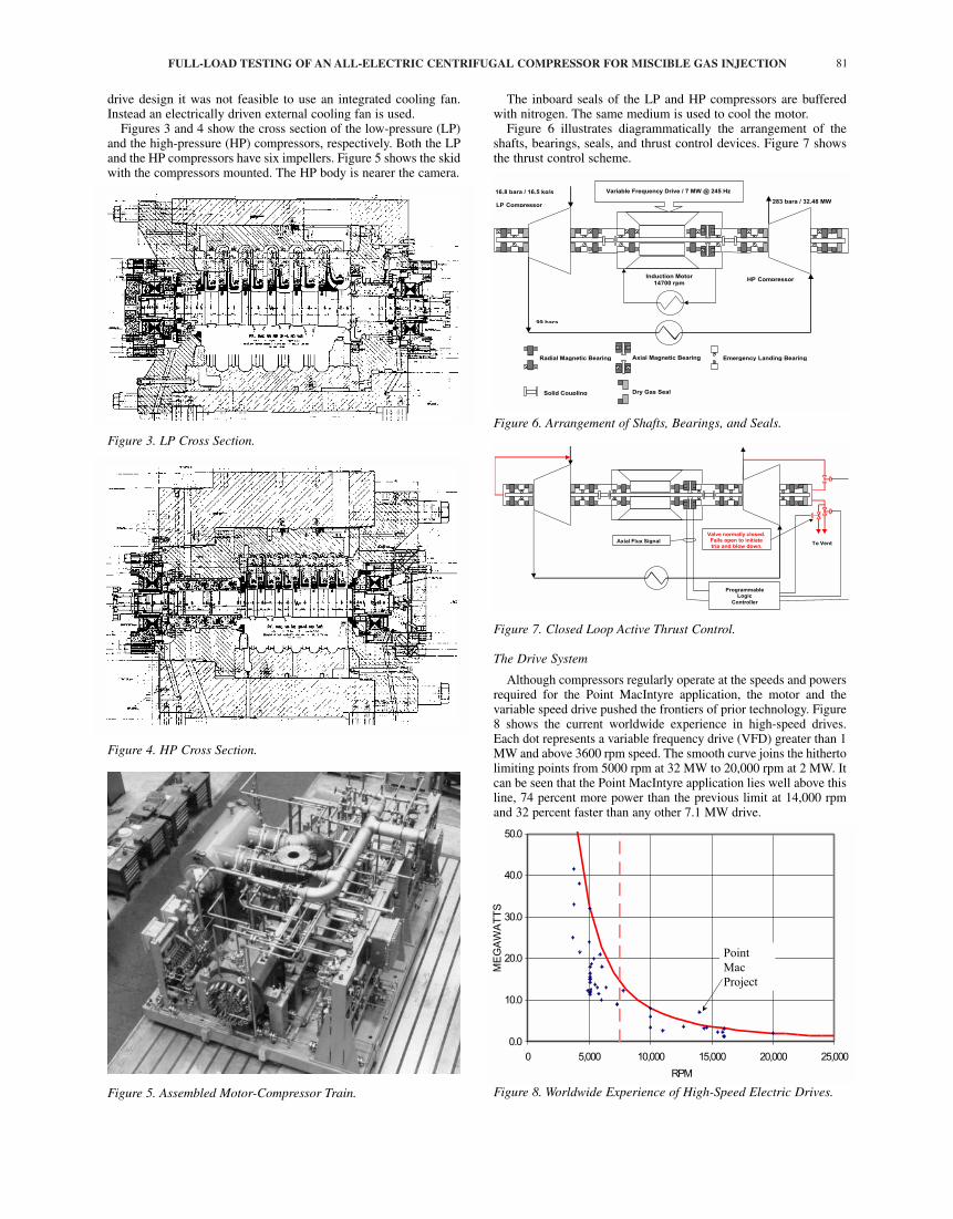
Figures 3 and 4 show the cross section of the low-pressure (LP)and the high-pressure (HP) compressors, respectively. Both the LPand the HP compressors have six impellers. Figure 5 shows the skidwith the compressors mounted. The HP body is nearer the camera.
Figure 3. LP Cross Section.
Figure 4. HP Cross Section.
Figure 5. Assembled Motor-Compressor Train.
The inboard seals of the LP and HP compressors are bufferedwith nitrogen. The same medium is used to cool the motor.
Figure 6 illustrates diagrammatically the arrangement of theshafts, bearings, seals, and thrust control devices. Figure 7 showsthe thrust control scheme.
Figure 6. Arrangement of Shafts, Bearings, and Seals.
Figure 7. Closed Loop Active Thrust Control.
The Drive System
Although compressors regularly operate at the speeds and powersrequired for the Point MacIntyre application, the motor and thevariable speed drive pushed the frontiers of prior technology. Figure8 shows the current worldwide experience in high-speed drives.Each dot represents a variable frequency drive (VFD) greater than 1MW and above 3600 rpm speed. The smooth curve joins the hithertolimiting points from 5000 rpm at 32 MW to 20,000 rpm at 2 MW. Itcan be seen that the Point MacIntyre application lies well above thisline, 74 percent more power than the previous limit at 14,000 rpmand 32 percent faster than any other 7.1 MW drive.
Figure 8. Worldwide Experience of High-Speed Electric Drives.
Dry Gas Seal
Radial Magnetic Bearing Axial Magnetic Bearing Emergency Landing Bearing
Solid Coupling
Induction Motor14700 rpm
LP Compressor
HP Compressor
LP Compressor
16.8 bara / 16.5 kg/s
99 bara
283 bara / 32.48 MW
Variable Frequency Drive / 7 MW @ 245 Hz
To Vent
ProgrammableLogic
Controller
Axial Flux Signal
Valve normally closed.Fails open to initiatetrip and blow down.
0.0
10.0
20.0
30.0
40.0
50.0
0 5,000 10,000 15,000 20,000 25,000
RPM
ME
GA
WA
TT
S
Point
Mac
Project
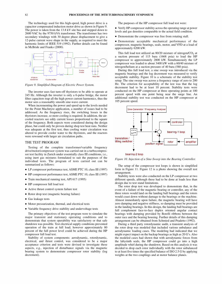
The technology used for this high-speed, high power drive is acapacitor compensated induction motor drive as shown in Figure 9.The power is taken from the 13.8 kV site bus and stepped down to2600 VAC by the 9750 kVA transformer. The transformer has twosecondary windings with 30 degree phase displacement to give a12-pulse current wave shape in the supply, as required to meet theharmonic limits of IEEE 519 (1992). Further details can be foundin McBride and Franks (2000).
Figure 9. Simplified Diagram of Electric Power System.
The inverter uses fast turn-off thyristors to be able to operate at245 Hz. Although the inverter is only a 6-pulse bridge, the motorfilter capacitors trap all the high power current harmonics, thus themotor sees a reasonably smooth sine-wave current.
When incrementing the power and speed up to the levels neededfor the Point MacIntyre application, a number of issues had to beaddressed. As the frequency rises, the switching losses in thethyristors increase, so more cooling is required. In addition, the air-cooled reactors see eddy current losses proportional to the squareof the frequency. Both aspects were considered during the designphase, but could only be proven during shop test heat runs. Neitherwas adequate at the first test, thus cooling water circulation wasaltered to provide cooler water to the thyristors, and the reactorswere rewound with larger air circulation paths.
THE TEST PROGRAM
Testing of the complete transformer/variable frequencydrive/motor/compressor system was carried out in a turbocompres-sor test facility in Zurich under essentially class III conditions, i.e.,using inert gas mixtures formulated to suit the purposes of theindividual tests. The program of tests carried out can besummarized as follows:
• LP compressor performance test, ASME PTC 10, class III (1997)
• HP compressor performance test, ASME PTC 10, class III (1997)
• Train mechanical running test, API 617 (1995)
• HP compressor full load test
• Active thrust control system failure test
• Rotor drop test (magnetic bearing failure)
• Gas leakage tests
• Motor pressurization, thermal, and electrical tests
• Variable frequency drive stability and undervoltage tests
The primary objectives of the test program were to simulate themajor transient and stationary operating conditions and todemonstrate that system operability was satisfactory or that safeshutdown was possible. Test electrical supply conditions preventedoperation of the train at full load; however approximately 80percent of the full power level could be achieved during the HPcompressor full load test.
Stability of system components: aerodynamic, rotordynamic,electrical, and thrust control, was considered to be a majoracceptance criterion and tests were devised to investigate theseaspects, e.g., injection of disturbance signals via the magneticbearing system to demonstrate compressor rotor stability (logdecrement).
The purposes of the HP compressor full load test were:
• Verify HP compressor stability across the operating range at powerlevels and gas densities comparable to the actual field condition.
• Demonstrate the compressor was free from rotating stall.
• Demonstrate acceptable mechanical performance of thecompressor, magnetic bearings, seals, motor, and VFD at a load ofapproximately 6200 kW.
This full load test utilized an 80/20 mixture of nitrogen/CO2 ata suction pressure of 115 bara (1668 psia) to load the HPcompressor to approximately 2800 kW. Simultaneously the LPcompressor was loaded to about 3400 kW with a 60/40 mixture ofnitrogen/helium at a suction pressure of 40 bara (580 psia).
During this full load test, a sine sweep was introduced via themagnetic bearings and the log decrement was measured to verifyacceptable stability. Figure 10 is a schematic of the stability testsetup. The sine sweep was across a frequency range of zero to 200Hz. The criterion for acceptability of the test was that the logdecrement had to be at least 10 percent. Stability tests wereconducted on the HP compressor at three operating points at 100percent speed with one point being near the surge line. Anadditional stability test was conducted on the HP compressor at105 percent speed.
Figure 10. Injection of a Sine-Sweep into the Bearing Controller.
The setup of the compressor test loops is shown in simplifiedform in Figure 11. Figure 12 is a photo showing the overall testarrangement.
Stability tests were also conducted on the LP compressor at twodifferent speeds, although these had to be done at loads less thandesign due to test stand limitations.
The rotor drop test was developed to demonstrate that, in theevent of a failure of the magnetic bearing or controller, any of thethree rotors would land on the landing ball bearings and the rotorswould coast down without damage to the bearings or the machine.Almost immediately upon failure, the magnetic bearing will havezero damping and negative stiffness, so damping must be providedin the landing bearings. In this design, the landing ball bearings arefull complement face-to-face duplex oriented angular contactbearings with damping provided by Borelli ribbons between theouter race and the bearing housing. Further details of this dampingarrangement can be obtained from Schmied and Pradetto (1992).
During a third party rotordynamic audit, a transient analysis ofthe rotor drop was modeled that included various unbalance andaerodynamic loading cases. The modeling had indicated that wemight expect impact on the backup bearings as high as 20 G’s. Alsothe modeled cases had shown that with aerodynamic forces fromthe labyrinth seals, the HP compressor could go into a highamplitude whirl during the shutdown. Based on this analysis it wasdecided to drop each rotor individually with the rotor unbalancedto at least five times the specified balance of ISO 2.5 G by applyingweights at the two couplings and at motor balance planes.
PROCEEDINGS OF THE 30TH TURBOMACHINERY SYMPOSIUM82
6 pulse
inverter
Motor filter
diverter
12 pulse rectfier
9750kVA
transformer
Motor

FULL-LOAD TESTING OF AN ALL-ELECTRIC CENTRIFUGAL COMPRESSOR FOR MISCIBLE GAS INJECTION 83
Figure 11. Compressor Test Loop Arrangement, Simplified.
Figure 12. Shop Test—View from Compressor End.
Failure was considered unlikely for more than one magneticbearing system at a time because its own controller cabinet controlledeach of the three rotors, and each cabinet was provided withindividual uninterruptible power supplies. Also the magnitude ofimpact forces was comparable regardless of dropping the three bodiesindividually or simultaneously according to the transient model.
The tests were conducted with the machine at 14,000 rpm and5400 kW so that the compressors provided sufficient aero brakingto slow the rotor down to less than 6000 rpm within a minimumtime (around 10 seconds). Longer periods of operation on thesenonlubricated ball bearings would have been damaging. A powerfailure of a single bearing cabinet was simulated by switching offthe power to the cabinet while simultaneously tripping power to thedrive. The magnetic bearings were reactivated after about 5 to 7seconds because of concerns that aerodynamic braking might notbe sufficient to slow the system down adequately to preventthermal damage to the bearings. Each rotor was tested in this way.
During the drops, rotor vibration position and phase wererecorded at each of the six bearings and processed throughoscilloscopes and fast Fourier analyzers. After each drop test the
compressors were shutdown, cooled, and the radial and axial ballbearing clearances were reconfirmed. The magnetic bearingcontroller has a diagnostic feature that allows the landing bearingclearance to be checked after shutdown by levitating the rotor andmoving it across the clearance. After all drop tests were completed,the two compressors were disassembled and all bearings andcompressor labyrinths were visually inspected.
HIGHLIGHTS FROM TEST RESULTS
Overload of the Radial Magnetic Bearings
When substantial gas pressure was first introduced into thecompressor casings, the magnetic bearing on the drive end of theLP compressor tripped off due to excessive current. This occurredwhile the rotor was levitated by the magnetic bearings but notrotating. The radial load capacity of the compressor bearings, withsilicon iron armatures, was 2000 N (450 lb), which was more thandouble the load to be supported.
Each magnetic bearing has a proportional-integral controller thatattempts to force the rotor to the center of the bearing. Becausesolid couplings connect the compressor and motor shafts, anydeviation of the centers of the six radial bearings from a straightline causes reaction forces at the radial bearings, with the rotoracting like a statically indeterminate beam on six supports. Thusthe increase in bearing current indicated that introducing gaspressure was causing the bearing centers to move off line.
The load supported by each bearing can be calculated from thecurrent applied to the armature coils. Before gas pressure wasintroduced, these loads were as expected for the rotor weights plusthe cold alignment offsets for thermal growth. This confirmed theinitial alignment of the LP and HP compressor bodies, and themotor, was correct prior to introducing pressure.
Referring back to Figure 7, note that gas pressure from the LPsuction acts on the gas seal at the outboard end of the LP shaft. Theresulting axial thrust on the shaft is balanced by pressure on the gasseal on the opposite end of the shaft. The thrust controller adjuststhis pressure to produce zero net thrust. However, the resultingreaction force on the LP and the HP compressor bodies is about 15metric tons (17 tons), at rated pressures, pushing each compressorbody outboard. This thrust is larger than a conventional train withbalance pistons. Massive axial members at the bearing centerlineheight prevent bending of the baseframe due to the large axial force.
The axial reaction force from each body is transmitted to theinboard pedestal by a transverse key, shown in Figure 13, designedto allow for radial thermal expansion. This arrangement has beenused successfully for years with solid coupled shafts. The key hasa shim on its top side to support the body at the correct height forshaft alignment.
Figure 13. LP Compressor Support Feet.
Instrument Air
CO2N2 He
HP Compressor Loop LP Compressor Loop
LP Compressor Support Feet

Figure 14 shows that axial thrust and its reaction act on this keyin opposite directions, but not at the same elevation. This producesa couple, which tends to rotate the key. Because the shim was ontop of the key, any rotation lifts the compressor body causing theproblem. To fix the problem, the shim was removed from the topof the key, so that key rotation would not lift the compressor. Asshown in Figure 15, a shim was placed beside the key, directlybetween the foot and the pedestal, to set the vertical alignment.Alignment and magnetic bearing currents have been satisfactorysince this change. The silicon iron armatures of the magneticbearing were replaced with cobalt iron armatures, thus providingadditional capacity against any other misalignment problems.
Figure 14. Problem Caused by Shim on Top of Key.
Figure 15. Fix—Move Shim.
Thrust Control Fail-Safe Test
During initial testing at high pressure, the thrust control failedand the drive shut down. While coasting to a stop, the resultingload on the landing bearing in the motor exceeded the bearingcapacity with minor consequential damage. A review of theprotective system recommended adding a fail-safe design, whichwould prevent excessive thrust in case of loss of thrust control.
This was accomplished using existing hardware. One port of thedigital control valve now fails open, and the drive trips off on lossof thrust control. The port size is matched to the system pressureand volume characteristics to approximate the action of thecontroller while the compressor is coasting to a stop. The fail-openvalve is shown in Figure 7. The digital valve is shown in Figure 16.(The valve is called digital because, starting with the smallest port,
each subsequent port has twice the area of the last. Also the portsmust be either open or closed.)
Figure 16. Digital Thrust Control Valve.
The port size was calculated using the test loop piping volumesand the test gas composition and states. The calculation wasconfirmed by tripping the drive with the controller active andobserving the digital valve, to see if the port area actuated by thecontroller was the same as the port area chosen for the blow-down.Figure 17 plots the test results of compressor speed and of port areaas a function of the coastdown time. The outlet valve cycledbetween 1.5 and 3 mm2 (0.0023 to 0.0047 in2), confirming thecalculated port area. Blow-down calculations for the fieldinstallation determined a different port size is required with thecompressor installed at Point MacIntyre.
Figure 17. Valve Openings upon Trip.
To confirm that the thrust control system is fail-safe, the thrustcontroller power supply was shut off while the compressor wasoperating at high pressure and at 11,500 rpm. The compressorautomatically tripped, as designed, and the fail-open port actuated.Figure 18 shows the resulting thrust, as measured from themagnetic thrust bearing flux, versus time during coastdown. RPMis also shown. The maximum measured thrust was less than 10,000N (2200 lb) compared to the magnetic bearing capacity of 25,000N (5600 lb), a comfortable margin.
If the compressor surges, the thrust will vary rapidly, and thecontroller will try to follow. Figure 19 shows the action of the thrustcontroller when surge was deliberately introduced during the high-pressure test. During the transient, the thrust was measured by themagnetic bearing flux. The thrust force exceeded trip limits, and thedrive was tripped. A touch was recorded on the landing bearing, butno damage occurred. This test demonstrated that no damage wouldoccur even if the surge control system failed to prevent surge.
PROCEEDINGS OF THE 30TH TURBOMACHINERY SYMPOSIUM84
0
0.5
1
1.5
2
2.5
3
3.5
0 1 2 3 4 5 6 7 8 9 10 11 12 13 14 15 16 17 18 19 20
Time [s]
va
lve
are
a [
mm
^2
]
0
2000
4000
6000
8000
10000
12000
14000
Sp
ee
d [
rpm
]
Inlet
Outlet
Speed
Shim on top of key
New shim here

FULL-LOAD TESTING OF AN ALL-ELECTRIC CENTRIFUGAL COMPRESSOR FOR MISCIBLE GAS INJECTION 85
Figure 18. Thrust Panel Failure Test.
Figure 19. Surge Test of Thrust Controller.
Measurement of Rotor Stability (Log Decrement)
Centrifugal compressors operating at the pressure and gasdensity required for Point MacIntyre raise concerns aboutrotordynamic stability against self-excited subsynchronousvibrations. With magnetic bearings, the log decrement can bemeasured at full pressure, full speed operation, to confirm therotordynamic design. A frequency-swept sine-wave signal wasintroduced into the magnetic bearing controller to perturb the rotorlateral vibrations. Considering the rotor as a linear dynamicsystem, the log decrement can be determined by the width of thedynamic response at the fundamental bending frequency. Figure 20shows, for the 72 Hz mode, a response width of 14 Hz at the half-power point. The corresponding log decrement is 0.61, indicatingsatisfactory rotor stability.
No rotating stall could be found in the operating map of eithercompressor. Both the LP and the HP compressors have vaneddiffusers on every stage.
Rotor Drop Test
As discussed under section “THE TEST PROGRAM” above,magnetic bearing control failure was simulated by turning offpower to each of the three control cabinets, one test at a time. Thusone body drops onto the landing bearings, while the other two aresupported by the magnetic bearings. Bearing control failureinitiates a trip of the compressor train, which then coasts to a stop.The bearing control power was reenergized after the rotor responsewas demonstrated, as a practical step to avoid excessive landingbearing wear on test. Figure 21 shows the HP compressor drop,starting at 14,000 rpm at time zero, with the bearing to bereenergized at 7000 rpm. As the drive had tripped, the train coaststoward 0 rpm, but decelerates ever more slowly because the gas inthe test loop is being released simultaneously.
Figure 20. Log Decrement Measurement During High Pressure Test.
Figure 21. HP Rotor Drop Test—Speed Versus Time.
Figure 22 shows a waterfall plot of the vibration spectra duringthe HP drop test. Initially, at 14,000 rpm, two subsynchronousmodes appeared, one at 70 Hz, and a second at 150 Hz. It isinteresting to see two instability frequencies, instead of only one ascommonly observed. When the magnetic bearing is reenergized, atransient is apparent due to the step function in force driving therotor back to the center of the bearing. The subsynchronous modesdrop out after the spectrum taken at 10,500 rpm. Subsynchronousnoise is suppressed after the bearing is reenergized.
Figure 22. HP Rotor Drop Test—Vibration Spectra Waterfall Plot.
-30000
-20000
-10000
0
10000
20000
30000
-10 -5 0 5 10 15 20 25 30 35
Time [sec]
Th
rust
[N]
0
2000
4000
6000
8000
10000
12000
Sp
eed
[rp
m]
Magnetic bearing capacity
Digital valve
cycling
Surge event starts
Magnetic
bearing
flux, L & R
Trip
setting
level
Digital
valve
signals
TIME
RPM
(drop
at
14000)
Time in seconds
____de-energize magnetic bearing
(initiates shut down)
___re-energize magnetic bearing

Figure 23 shows the orbit at the HP nondrive-end bearing duringthe drop test. The circular orbit at the center, of 20 µm (0.8 mil)diameter, is the synchronous response prior to the drop. The 150µm (6 mil) radius represents the touch circle of the landingbearing. The 220 µm (9 mil) radius represents the maximum orbitof the landing bearing when the damper ribbon behind the bearingis fully deflected.
Figure 23. HP Rotor Drop Test—Shaft Orbit.
Figure 24 is a photograph of the rotor and its labyrinth seals afterthe drop test. Figure 25 is a photograph of the stationary portion ofthe labyrinth seals. Note the swirl brakes at the entry side of theseals. The labyrinths were not damaged by the drop test, showingthe rotor vibrations were controlled by the landing bearings.
Figure 24. HP Rotor and Labyrinth Seals after Drop Test.
Drive Tuning
The entire drive and its supply transformer were shipped to themanufacturer in Zurich for combined testing with the motor andcompressor. To achieve the tests required a special tap being addedto the transformer at the design stage to get full secondary voltswith the test station supply of only 11 kV at 50 Hz compared withthe site condition of 13.8 kV at 60 Hz. In addition, since the sourceimpedance was significantly higher than the normal siteconditions, changes were required to the current loop gain toachieve the desired response times.
Starting up a VFD system on a motor with magnetic bearingsrequires a very cautious approach as the drive requires the motor to
Figure 25. HP Stator and Labyrinth Seals.
run to set the control responses, and yet the bearing controls needto be tuned before any significant speeds can be achieved. Both theVFD engineers and the bearing experts were present while thespeed was progressively increased, and the compressor load had tobe adjusted at each stage to provide only enough torque to ensurethe stability of the whole system.
To maximize the benefit of prior experience, the software wasadapted from standard versions in use on other high power drivesbut at lower frequencies. It was found on shop test that the high-speed software was limiting and some of the unnecessary featureshad to be removed to achieve the full 245 Hz frequency. Inevitablythe changes had to be debugged progressively as each oneappeared during the test program, but eventually the motor was runstably at full speed at about 6100 kW, which was the maximumload achievable on the test bed. Figure 26 shows the quality of themotor volts and amps at 245 Hz.
Figure 26. Motor Volts and Amps at Full Speed.
TEST SUCCESSES
The successes achieved during testing can be directly related tothe innovative features of the compression system. Starting withthe variable frequency drive: despite the problems encountered intuning the controls software, it could be demonstrated on test thatthe design concept of the drive is fully adequate for a power-speedduty that is well outside previous experience (refer to Figure 8).The same can be said for both thermal and mechanical design ofthe induction motor. Although the demonstrator motor wasdesigned for higher speed (20,000 rpm as opposed to 14,700 rpm),the power level for the Point MacIntyre application is more thanthree times higher. This is of particular significance for the coolingsystem of the motor.
A train with six radial magnetic bearings and axially rigidcouplings was also a novelty. In such a system there is considerablepotential for interaction between the individual bearing controllers.
PROCEEDINGS OF THE 30TH TURBOMACHINERY SYMPOSIUM86
____Touch
inner
race
____Damper
ribbon
deflected
1 >2 >
1) Red = Output volts: 5 Volt 500 us
2) Blue = Output current 2 Volt 500 us
VFD output amps
VFD output volts

FULL-LOAD TESTING OF AN ALL-ELECTRIC CENTRIFUGAL COMPRESSOR FOR MISCIBLE GAS INJECTION 87
However, the actual time required to tune the bearing system ontest corresponded to the predictions of the bearing manufacturer.Rotorbearing behavior was also close to the rotordynamicpredictions. Independent predictions of the rotor behavior during adrop incident were confirmed on test. Thus further validation of thenumerical tools used to predict rotorbearing performance wasobtained from the test program.
Finally, the concept of a train using active thrust control, withoutbalance piston, was shown to be feasible for residual thrust levelsmuch higher than normally encountered in a conventional high-pressure train. In particular, the strenuous test conditions showedthat the thrust controller could accommodate the rapid transients,which occur during trip. This confirms the overall power savingsthat can be achieved by eliminating the balance piston losses onsuch high-pressure machinery.
COMMISSIONING IN ALASKA
After the equipment was received in Alaska, it was installed,grouted, and aligned. All piping and vessels were thoroughlycleaned and the system then closed and pressure tested. The VFD,all control valves, instruments, and controls were functionallychecked statically.
To assure successful long-term operation, a startup/test plan wasdeveloped. The following phases and goals for the testing wereestablished:
• Cleanup Run(s)—
• Debug first part of start sequence to allow machine operationon 21 molecular weight lean gas.
• Verify stability of magnetic bearings and VFD with operationat a loading of about 3900 kW.
• Circulate system in complete recycle for sufficient time toverify cleanliness of suction strainers.
• Verify surge control settings and adjust as necessary.
• Verify proper functioning of dry gas seal system, motor, drive, etc.
• Confirm aerothermal performance data for the compressors.
• Monitor alignment and vibrations to assure acceptablemechanical performance.
• Mechanical Run(s)—
• Debug remainder of start sequence to allow machineoperation on blended gas between 27 and 32 molecular weight.
• Verify all other aspects of machine operation (as listed aboveunder the cleanup runs) at a load of approximately 7000 kW.
The most difficult part of commissioning the equipment proved tobe debugging the startup sequence and tuning the various processcontrollers. The compressors are designed to start operation in fullrecycle on the 21 molecular weight lean gas. During this period ofoperation, the compressors are in full recycle and the process systemis warmed up. After reaching the specified temperature, a mixingvalve is opened in the inlet piping that blends a proper proportion ofa 36 molecular weight gas with the 21 molecular weight lean gas toachieve the required composition for optimum miscible injection.
The blending was particularly sensitive to valve tuning andsystem dynamics. Much effort was required to successfully startthe equipment without tripping. Early attempts saw very rapidpressure and compositional changes within the compressionsystem that ultimately resulted in the machine tripping on highaxial rotor movements.
Another factor also leading to trips on axial position was thesequencing of a control valve that admitted gas to the LP balancepiston. The intent of this valve was to bias the axial thrust of therotor when at normal operating conditions. The quarter-turn valvewas originally designed to switch open at 173 barg (2500 psig)discharge to provide an optimum control range for the active thrust
controller. This action along with system transient response as therich gas was blended proved troublesome. Eventually a solutionwas to change the valve to a control valve and modify the pressureat which the valve was opened.
Other aspects of machinery performance, vibration, stability,and aerothermal performance were found to be completelyacceptable.
The machine was in service at design conditions for about twoweeks when a short occurred within the stator windings of themotor. An internal shroud, made from copper alloy, was positionedaround the rotor short-circuit end ring area. It had broken loose andcontacted the stator windings causing the short. Figure 27 is apicture of the bearing shroud that had become loose. The shroudhad also contacted the rotor, but did only minor damage to the rotorand was easily corrected by grinding and polishing.
Figure 27. Loose Bearing Shroud.
This shroud was an axial cylindrical extension of the motorbearing housing and was attached on this bearing housing. Figure28 is a picture of the motor bearing housing and rotor indicatingwhere the bearing shroud was attached. Inspections of the failedpieces revealed that the cap screws that held the shroud in placehad broken or backed out, allowing the shroud to fall into the rotorand into the stator windings. The flanged area of the bearinghousing and the shroud were also pitted from arcing.
Figure 28. Motor Bearing Housing and Rotor.
This shroud around the rotor short-circuit ring area had beenadded uniquely for this job, assuming it was necessary to protect

this rotor short-circuit ring area from the stator magnetic fields.This modification had been done during the string tests in Zurich.Based on more recent successful experience without this shroudbeing installed, it became obvious that this shroud was unnecessaryand not recommended. The changes include:
• Removal of the axial shroud around the short-circuit ring area.
• Tinning the copper parts of the bearing housing to protect themfrom corrosion rather than painting them.
• Bonding the two shroud segments together and to the bearinghousing.
• Changing the fixation screws from steel to brass.
At this writing, May 2001, the stator is being rewound at themanufacturing facility in Belgium.
CONCLUSIONS
Thorough testing helped develop and convincinglydemonstrated the following features in a high-pressure centrifugalcompressor:
• Active thrust control with a fail-safe feature
• Magnetic bearings on a multicasing rigidly coupled rotor
• A unique combination of speed and power in a variablefrequency drive and induction motor
The degree of testing required to confirm the new designfeatures was well justified by the number of problems found andcorrected. We believe corrections at the operating site duringcommissioning would have been much more expensive thancorrections at the vendor’s works. The problem with the motorinternal shroud took about two weeks running at design conditionsto develop, and thus was not discoverable on a short term test in thevendor’s works.
The software for the variable frequency drive showed promisingflexibility and useful diagnostic capability. Use of a softwaresimulator to thoroughly exercise the drive software prior to tuningthe drive will be considered for future applications.
REFERENCES
API Standard 617, 1995, “Centrifugal Compressors for Petroleum,Chemical, and Gas Service Industries,” Sixth Edition,American Petroleum Institute, Washington, D.C.
ASME PTC-10, 1997, “Compressor and Exhausters,” AmericanSociety of Mechanical Engineers, New York, New York.
Gilon, D. C. and Marriott, A. C., 1993, “Initial Experience with aNew High-Speed, High-Pressure, Oil-Free Motor CompressorUnit (HOFIM),” Proceedings of the Fifth European Congresson Fluid Machinery for the Oil, Petrochemical and RelatedIndustries, IMechE, The Hague, The Netherlands, pp. 221-228.
Graham, A. D., 1993, “Development of a 2 MW, 20,000 RPMInduction Motor Drive,” Proceedings of the InternationalSymposium on Industrial Electronics, IEEE, Budapest,Hungary, pp. 44-48.
IEEE 519, 1992, “Recommended Practices and Requirements forHarmonic Control in Electrical Power Systems,” Institute ofElectrical and Electronic Engineers, Washington, D.C.
McBride, W. E. and Franks, J., 2000, “9500 HP High-Speed MotorDriven Compressor,” IEEE Autumn Conference, San Antonio,Texas, Petroleum and Chemicals Industries Council, Paper No.PCIC-16, pp. 155-163.
Schmied, J. and Pradetto, J. C., 1992, “Behavior of a One TonRotor Being Dropped into Auxiliary Bearings,” Proceedings ofthe Third International Symposium on Magnetic Bearings,Washington, D.C.
ACKNOWLEDGEMENT
The authors would like to thank all the coworkers from SulzerTurbo, Ltd., Stoyerman Controls Ltd., British PetroleumExploration, and ExxonMobil who have contributed to this paper.This paper reflects the views of its authors and does not necessarilyreflect the views of Exxon Mobil and/or British PetroleumExploration and/or Sulzer Turbo Ltd. and/or Stoyerman ControlsLtd.
PROCEEDINGS OF THE 30TH TURBOMACHINERY SYMPOSIUM88