fuel material technology report - a.n.t. international
TRANSCRIPT


FUEL MATERIAL TECHNOLOGY REPORT
Volume I
Authors
Brian Cox University of Toronto, Ontario, Canada
Friedrich Garzarolli Erlangen, Germany
Ron Adamson Zircology Plus, Fremont, California, USA
Peter Rudling ANT International, Skultuna, Sweden
Alfred Strasser Aquarius Services, Sleepy Hollow, New York, USA
Reviewed by
Ron Adamson Zircology Plus, Fremont, California, USA
October, 2006
Advanced Nuclear Technology InteITlational
KrongjutaIVagen 2C
SE-730 50 SKULTUNA
Sweden
www.antinternational.com
NT INTERNATIONAL

Fuel Material Technology Report
DISCLAIMER
The information presented in this report has been compiled and analysed by Advanced Nuclear Technology International Europe AB (ANT International) and its subcontractors. ANT International has exercised due diligence in this work,
but does not warrant the accuracy or completeness of the information. ANT International does not assume any responsibility for any consequences as a
result of the use of the information for any party.
Copyright © Advanced Nuclear Technology International Europe AB, ANT International, 2006. This information is the property of Advanced Nuclear Technology International Europe AB or is licensed for use by Advanced Nuclear Technology International Europe AB by its custom ers or partners. The inform ation may not be given to, shared with, or cited to third party, used for unauthorised purpose, or be copied or reproduced in any form without the written permission of Advanced Nuclear Technology International Europe AB.
II(XII)

Fuel Material Technology Report
ABBREVIATIONS
ABSS ABWR ADU AECL ANT AOA AOD AP ASTM ASME AUC B&W BCC BOL BWR CANDU CE CEZUS CF CGR CILC CR CRD CRDM CRUD CPR DF DFBN DHC DNB DNBR DO DX EAC EB ECP ELS EOL ESSC FA
AB Sandvik Steel Advanced BWR Ammonium DiUranate Atomic Energy of Canada Laboratories Advanced Nulear Technology Axial Offset Anomaly Axial Offset Deviation Advanced PWR American Society for Testing and Materials American Society of Mechanical Engineers Ammonium Uranyl Carbonate Babcock&Willcox Body Centered Cubic Beginning of Life Boiling Water Reactor Canadian Deuterium Uranium Combustion Engineering Companie Europen Ziconium Ugine Sandvik Corrosion Fatigue Crack Growth Rate Crud Induced Localized Corrosion Control Rod Control Rod Drive Control Rod Drive Mechanism Chalk River Unidentified Deposits Critial Power Ratio Debris Filter Debris Filter Bottom Nozzle Delayed Hydride Cracking Departure from Nucleate Boiling Departure of Nucleate Boiling Ratio Dissolved Oxygen Duplex Environmentally Assisted Cracking Electron Beam Electrochemical Corrosion Potential Extra-Low Sn End Of Life Enhanced Spacer Shadow Corrosion Fuel Assembly
Copyright © Advanced Nuclear Technology International Europe AB, ANT International, 2006. This information is the property of Advanced Nuclear Technology International Europe AB or is licensed for use by Advanced Nuclear Technology International Europe AB by its custom ers or partners. The inform ation may not be given to, shared with, or cited to third party, used for unauthorised purpose, or be copied or reproduced in any form without the written permission of Advanced Nuclear Technology International Europe AB.
III(XII)

Fuel Material Technology Report
FC FDI FGR GC GE GNF GT HAZ HCP HPA-4 HPUF HTP HWC HWR IAEA IASCC I.D. IFBA IFM IGSCC IPHT IRI IT IZNA KKM KNFC KWU L LAS LHGR LOCA LPBN LTP LWR MA MDA MF MHI MOX MRP NDA NFl
Fuel Channel Fuel Duty Index Fission Gas Release Guide Channels General Electric Global Nuclear Fuel Guide Tube Heat Affected Zone Hexagonal Close-Packed High Performance Alloy Hydrogen Pick Up Fraction High Thermal Performance Hydrogen Water Chemistry Heavy Water Reactor International Atomic Energy Agency Irradiation Assisted Stress Corrosion Cracking Inner Diameter Integral Fuel Burnable Absorber Intermediate Flow Mixing Intergranular Stress Corrosion Cracking In Process Heat Treated Incomplete Rod Insertion Instrument Tube Information on Zirconium Alloys KernKraftwerk Muhleberg Korea Nuclear Fuel Company KratwerkUnion Laser Low Alloy Steels Linear Heat Generation Rate Loss of Coolant Accident Low Pressure drop Bottom Nozzle Low-Temperature Process Light Water Reactor Mill Annealed Mitsubishi Developed Alloy Magnetic Force Mitsubishi Heavy Industries Mixed OXide Material Reliability Program New Developed Alloy Nuclear Fuel Industries
Copyright © Advanced Nuclear Technology International Europe AB, ANT International, 2006. This information is the property of Advanced Nuclear Technology International Europe AB or is licensed for use by Advanced Nuclear Technology International Europe AB by its custom ers or partners. The inform ation may not be given to, shared with, or cited to third party, used for unauthorised purpose, or be copied or reproduced in any form without the written permission of Advanced Nuclear Technology International Europe AB.
IV(XII)

Fuel Material Technology Report
NMC NPD NPP NRC NSSS NG NWC O.D. OPG PCI PCMI PGP PWR PWSCC QA QC R RBMK
RCCA RCS RFA RIA RPV RT RVH RXA SCC SCRI SG SGHWR SICC SLAR SOCAP SS SSM STR SRA SPP TEM TGSCC TIG
Noble Metal Chemistry Nuclear Power Demonstration reactor Nuclear Power Plant Nuclear Regulatory Commission Nuclear Steam Supply System Nuclear Grade Normal Water Chemistry Outer Diameter Ontario Power Generation company Pellet Cladding Interaction Pellet Cladding Mechanical Interaction Precipitate Growth Parameter Pressurised Water Reactor Primary Water Stress Corrosion Cracking Quality Assurance Quality Control Resistance Reaktor Bolshoi Mozhnosti Kanalov (in English Large Boiling Water Channel type reactor) Rod Cluster Control Assemblies Reactor Coolant System Robust Fuel Assembly, Reactivity Initiated Accident Reactor Pressure Vessel Room Temperature Reactor Vessel Head Recrystallised Annealed Stress Corrosion Cracking Stress-Corrosion Susceptibility Index Steam Generator Steam Generating Heavy Water Reactor Strain Induced Corrosion Cracking Spacer Location and Repositioning Second Order Cumulative Annealing Parameter Stainless Steel Sandvik Special Metal Special Topic Report Stress Relieved Annealed Second Phase Particle Transmission Electron Microscopy Transgranular Stress Corrosion Cracking Tungsten Inert Gas
Copyright © Advanced Nuclear Technology International Europe AB, ANT International, 2006. This information is the property of Advanced Nuclear Technology International Europe AB or is licensed for use by Advanced Nuclear Technology International Europe AB by its custom ers or partners. The inform ation may not be given to, shared with, or cited to third party, used for unauthorised purpose, or be copied or reproduced in any form without the written permission of Advanced Nuclear Technology International Europe AB.
V (XII)

Fuel Material Technology Report
TM TSHT TSS TT UK US UT VVER WABA WZ ZIRAT ZIRLO
Transition Metal Tube Shell Heat Treated Terminal Solid Solubility Thermal Treatment United Kingdom Ultimate Strength Ultrasonic Testing V oda V oda Energo Reactor Wet Annular Absorber Western Zirconium Zirconium Alloy Technology (Program) Zirconium Low Oxidation
Copyright © Advanced Nuclear Technology International Europe AB, ANT International, 2006. This information is the property of Advanced Nuclear Technology International Europe AB or is licensed for use by Advanced Nuclear Technology International Europe AB by its custom ers or partners. The inform ation may not be given to, shared with, or cited to third party, used for unauthorised purpose, or be copied or reproduced in any form without the written permission of Advanced Nuclear Technology International Europe AB.
VI(XII)

Fuel Material Technology Report
UNIT CONVERSION
T(K) 273 289 298 373 473 573 633 673 773 783 793
823 833 873 878 893 923 973
1023 1053 1073 1136 1143 1173 1273 1343 1478
MASS
kg 0.454
1
TEMPERATURE
°C + 273.15 = K
°C*1.S +32 = of
T (0C) 0
16 25
100
200
300
360 400
500
510 520
550 560 600
605 620 650 700
750 780 SOO
863 870 900
1000
1070 1204
lbs 1
2.20
T(OF) 32 61 77
212 392 572 680 752 932 950 968
1022 1040 1112 1121 1148 1202 1292 1382 1436 1472 1585 1598 1652 1832 1958 2200
DISTANCE
x (11m) x (mils) 0.6 0.02
1 0.04 5 0.20
10 0.39 20 0.79 25 0.98
25,4 1.00
100 3.94
PRESSURE
bar MPa psi 1 0.1 14
10 1 142 70 7 995
70,4 7.04 1000
100 10 1421 130 13 1847 155 15.5 2203 704 70.4 10000
1000 100 14211
STRESS INTENSITY FACTOR
MPa-Ym ksi-Yinch 0.91 1
1 1.10
Copyright © Advanced Nuclear Technology International Europe AB, ANT International, 2006. This information is the property of Advanced Nuclear Technology International Europe AB or is licensed for use by Advanced Nuclear Technology International Europe AB by its custom ers or partners. The inform ation may not be given to, shared with, or cited to third party, used for unauthorised purpose, or be copied or reproduced in any form without the written permission of Advanced Nuclear Technology International Europe AB.
VII(XII)

Fuel Material Technology Report
FOREWORD
The personal viewpoints and conclusions presented in the report that are beyond those quoted from references, are those of the individual authors and may not represent the collective view of all authors.
Throughout the report, references are given to previous Special Topical Reports furnished in the ZIRAT-5jIZNA-1 to ZIRAT-10jIZNA -5 Programs, that are available to ZIRA T-customers, and they are:
• "Impact of Irradiation on Material Performance" by Ron Adamson and Brian Cox, 2005.
• "Structural Behavior of Fuel and Fuel Channel Components" by Brian Cox, Friedrich Garzarolli, Peter Rudling, Alfred Strasser, 2005.
• "Corrosion of Zr-Nb Alloys" by Brian Cox, Friedrich Garzarolli and Peter Rudling, 2004.
• "Loss of Coolant Accidents, LOCA and Reactivity Initiated Accidents, RIA, in BWRs and PWRs" by Ron Adamson, Friedrich Garzarolli and Peter Rudling, 2004.
• "High Burnup Fuel Issues" by Ron Adamson, Brian Cox, Friedrich Garzarolli, Peter Rudling, Alfred Strasser, Gunnar Wikmark, 2003.
• "The Effects of Zn Injection (PWRs and BWRs) and Noble Metal Chemistry (BWRs) on Fuel Performance - an update" by Brian Cox, Friedrich Garzarolli, Peter Rudling, Alfred Strasser, 2003.
• "Corrosion of Zirconium Alloys" by Ron Adamson, Brian Cox, Friedrich Garzarolli, Peter Rudling, Alfred Strasser, Gunnar Wikmark, 2002.
• "Dimensional Stability of Zirconium Alloys", by Ron Adamson and Peter Rudling, 2002.
• "Water Chemistry and Crud Influence on Cladding Corrosion", by Gunnar Wikmark and Brian Cox, 2001.
• "Mechanical Properties of Zirconium Alloys", by Ron Adamson and Peter Rudling, 2001.
• "Manufacturing of Zirconium Alloy Materials", by Peter Rudling and Ron Adamson, 2000.
• "Hydriding Mechanisms and Impact on Fuel Performance", by Peter Rudling and Brian Cox, 2000.
Ron Adamson, Editor
Copyright © Advanced Nuclear Technology International Europe AB, ANT International, 2006. This information is the property of Advanced Nuclear Technology International Europe AB or is licensed for use by Advanced Nuclear Technology International Europe AB by its custom ers or partners. The inform ation may not be given to, shared with, or cited to third party, used for unauthorised purpose, or be copied or reproduced in any form without the written permission of Advanced Nuclear Technology International Europe AB.
VIII(XII)

Fuel Material Technology Report
CONTENTS
ABBREVIATIONS
UNIT CONVERSION
1
2 2.1 2.2 2.3 2.4 2.5 2.6
3 3.1 3.1.1 3.1.2 3.1.3 3.1.4 3.1.5 3.2
3.2.1 3.2.1.1 3.2.1.1.1 3.2.1.1.2 3.2.1.1.3 3.2.1.2 3.2.2 3.2.2.1 3.2.2.2 3.2.2.3 3.2.2.4 3.2.3 3.2.4 3.2.5 3.2.6 3.3 3.3.1 3.3.2 3.3.2.1 3.3.2.2 3.3.3 3.3.3.1 3.3.3.2 3.3.3.3 3.3.4 3.3.4.1 3.3.4.2
INTRODUCTION
GENERAL REACTOR CHARACTERISTICS INTRODUCTION PWR (ALFRED STRASSER) BWR (AL STRASSER) CANDU REACTORS (BRIAN COX) VVER (PETER RUDLING) RBMK REACTORS (BRIAN COX)
FUEL ASSEMBLY DESIGN GENERAL OUTLINE OF FUEL ASSEMBLY DESIGNS AND FUNCTIONS PWR and BWR (Alfred Strasser and Peter Rudhng) CANDU (Brian Cox) VVER (Brian Cox) RBMK (Brian Cox) Functions of Fuel Assembly Components (Peter Rudling) DESCRIPTIONS OF VARIOUS LWR FUEL VENDOR DESIGNS AND THEIR SPECIFICS (PETER RUDLING) AREVA NP PWR designs AFA3G HTP Mark BW and Mark B BWR design (all former Siemens designs) Westinghouse CENP PWR Fuel Old-ABB PWR Fuel Westinghouse PWR Fuel Westinghouse BWR Fuel GNF Mitsubishi NFl KNFC FUEL ASSEMBLY MATERIALS Introduction (Friedrich Garzarolli) Zirconium alloys (Friedrich Garzarolli) BWR Zirconium alloy, liners (Friedrich Garzarolh) PWR Zirconium alloy, DUPLEX (Friedrich Garzarolli) U02for BWRs and PWRs (Alfred Strasser) Design Bases and Functions Performance Parameters and Considerations Performance Experience MOX for BWRs and PWRs (Alfred Strasser) Design Bases and Functions Performance Parameters and Consideration
Copyright © Advanced Nuclear Technology International Europe AB, ANT International, 2006. This information is the property of Advanced Nuclear Technology International Europe AB or is licensed for use by Advanced Nuclear Technology International Europe AB by its custom ers or partners. The inform ation may not be given to, shared with, or cited to third party, used for unauthorised purpose, or be copied or reproduced in any form without the written permission of Advanced Nuclear Technology International Europe AB.
IX(XII)
III
VII
1-1
2-1 2-1 2-3 2-21 2-36 2-45 2-48
3-1 3-1 3-1 3-6 3-12 3-18 3-24
3-27 3-27 3-27 3-31 3-34 3-36 3-36 3-39 3-40 3-46 3-48 3-49 3-53 3-56 3-60 3-63 3-65 3-65 3-69 3-70 3-81 3-89 3-89 3-91 3-94 3-95 3-95 3-97

Fuel Material Technology Report
3.3.4.3 3.3.5 3.3.5.1 3.3.5.2 3.3.5.2.1 3.3.5.2.2 3.3.5.2.3 3.3.5.3 3.3.5.3.1 3.3.5.3.2 3.3.5.3.3 3.3.5.4 3.3.5.4.1 3.3.5.4.2 3.3.5.4.3 3.3.6 3.3.6.1 3.3.6.2 3.3.6.2.1 3.3.6.2.2 3.3.6.2.3 3.3.6.3 3.3.6.3.1 3.3.6.3.2 3.3.6.3.3
4 4.1 4.1.1 4.1.1.1 4.1.1.2 4.1.1.3 4.1.1.4 4.1.2 4.1.3 4.1.4
4.1.5 4.1.5.1 4.1.5.2 4.1.5.3 4.1.6 4.1.6.1 4.1.6.2 4.1.6.3 4.1.6.4 4.1.6.5 4.1.7 4.1.8 4.1.9 4.1.10
Performance Experience Burnable Absorbers (Alfred Strasser) Introduction (UGd)02 for BWRs and PWRs Design Bases and Functions Performance Parameters and Considerations Performance Experience Boron Burnable Absorbers for PWRs Design Bases and Functions Performance Parameters and Considerations Performance Experience Erbia Burnable Absorber Design Bases and Functions Performance Parameters and Considerations Performance Experience. ST AINLESS STEEL AND NICKEL BASE ALLOY COMPONENTS (Alfred Strasser) Introduction BWRs Design Bases and Functions Performance Parameters and Considerations Performance Experience PWRs Design Bases and Functions Performance Parameters and Considerations Performance Experience
FUEL ROD, ASSEMBLY AND PRESSURE TUBE PERFORMANCE FUEL ROD AND ASSEMBLY (AL STRASSER AND PETER RUDLING) Corrosion (Alfred Strasser) Temperature Materials (Zirconium Alloys) Hydrogen Pickup Water Chemistry Dimensional Changes (Ron Adamson, Alfred Strasser and Peter Rudhng) Ductility (Alfred Strasser) PC! (Pellet Gadding Interaction) and PCMI (Pellet Gadding Mechanical Interaction) (Peter Rudling) Fretting (Peter Rudhng) Grid-to-rod Fretting Debris Fretting Baffle jetting Manufacturing defect (Peter Rudhng) Primary Hydriding Weld Defects End Plug Piping Gadding Incipient Cracks Pellet defects Fuel rod collapse (Peter Rudling) Fuel failure degradation (Peter Rudhng) AOA (Peter Rudling) CANDU Pressure Tubes (Brian Cox)
Copyright © Advanced Nuclear Technology International Europe AB, ANT International, 2006. This information is the property of Advanced Nuclear Technology International Europe AB or is licensed for use by Advanced Nuclear Technology International Europe AB by its custom ers or partners. The inform ation may not be given to, shared with, or cited to third party, used for unauthorised purpose, or be copied or reproduced in any form without the written permission of Advanced Nuclear Technology International Europe AB.
X(XII)
3-98 3-98 3-98 3-99 3-99 3-100 3-101 3-101 3-101 3-103 3-103 3-105 3-105 3-105 3-106 3-106 3-106 3-110 3-110 3-110 3-112 3-112 3-112 3-114 3-114
4-1 4-1 4-8 4-11 4-14 4-15 4-16 4-18 4-24
4-27 4-30 4-31 4-33 4-36 4-38 4-38 4-42 4-42 4-42 4-42 4-43 4-45 4-45 4-46

Fuel Material Technology Report
4.1.10.1 4.1.10.2 4.1.10.3 4.1.10.4 4.1.11 4.1.11.1
5 5.1 5.2 5.3
6
7 7.1 7.2 7.2.1 7.2.1.1 7.2.1.2 7.2.2 7.2.2.1 7.2.2.2 7.2.2.3 7.2.2.4 7.2.3 7.2.3.1 7.2.3.2 7.2.3.3 7.2.4 7.2.4.1 7.2.4.2 7.2.5 7.2.5.1 7.2.5.1.1 7.2.5.1.2 7.2.5.2 7.3
7.3.1
7.3.2
7.3.3 7.3.3.1 7.3.3.2 7.3.3.3 7.3.3.4 7.3.3.4.1
Tube Elongation Diametral Creep Creep Sag Delayed Hydride Cracking (DHC) RBMK Pressure Tubes (Brian Cox) Fuel Channel Dimensional Stability
FUEL PERFORMANCE CODES (PETER RUDLING) INTRODUCTION FUEL ROD STATIC AND TRANSIENT CODES FUEL ROD STATIC CODE CALCULATIONS AND TREATMENTS OF UNCERT AINTIES
MANUFACTURING OF PRESSURES TUBES IN CANDU AND RBMK
4-47 4-49 4-50 4-52 4-53 4-53
5-1 5-1 5-3
5-4
REACTORS (BRIAN COX) 6-1
MANUFACTURING OF BWR AND PWR FUEL MATERIALS 7-1 CURRENT INDUSTRY SETUP (AL STRASSER AND PETER RUDLING) 7-1 FUEL AND PELLET MANUFACTURING (ALFRED STRASSER) 7-5 Raw materials 7-5 Uranium 7-5 Plutonium 7-8 Powder production 7-8 UF6Conversion 7-8 Pu Nitrate Conversion 7-8 Blending 7-9 Press Feed Preparation 7-14 Pellet manufacturing 7-15 Pressing 7-15 Sintering 7-16 Grinding 7-17 Handling 7-17 MOX Fuel 7-17 REPU Fuel 7-18 Burnable absorbers 7-19 Integral burnable absorbers 7-19 Gadolinia and Erbia 7-19 Integral Fuel Absorber (IFBA) 7-20 Individual burnable absorbers 7-20 ZIRCONIUM ALLOY COMPONENT MANUF ACTURING (PETER RUDLING AND ALFRED STRASSER) 7-21 Application of Zr components in the fuel assembly and industry structure (Alfred Strasser and Peter Rudling) 7-21 Relationship between fabrication, microstructure and performance (Alfred Strasser and Peter Rudhng) 7-27 Zirconium metal production (Peter Rudhng) 7-30 Introduction 7-30 Kroll Process 7-30 Other Processes 7-32 Ingot Melting Process 7-33 Process 7-33
Copyright © Advanced Nuclear Technology International Europe AB, ANT International, 2006. This information is the property of Advanced Nuclear Technology International Europe AB or is licensed for use by Advanced Nuclear Technology International Europe AB by its custom ers or partners. The inform ation may not be given to, shared with, or cited to third party, used for unauthorised purpose, or be copied or reproduced in any form without the written permission of Advanced Nuclear Technology International Europe AB.
XI(XII)
Fuel Material Technology Report
7.3.4 Tube shell production 7.3.4.1 Introduction 7.3.4.2 Forging Process 7.3.4.3 Beta-quenching 7.3.4.4 Extrusion 7.3.5 Tubing production (cladding, guide tubes, water rods) 7.3.5.1 Pilgering, intermediate anneals, cleaning, late quench 7.3.5.2 Final heat treatment and finishing operations 7.3.6 Bar stock 7.3.7 Spacer strips, Channel sheet 7.4 FUEL ROD (ALFRED STRASSER) 7.4.1 Fuel Rod Components 7.4.2 Assembly Procedure 7.4.3 Welding 7.4.4 Fuel Rod Loading 7.4.5 Pressurization 7.4.6 Quality Control (QC) Inspection 7.5 SP ACER GRIDS(ALFRED STRASSER) 7.5.1 Process Overview 7.5.2 Stamping 7.5.3 Assembly and Welding 7.5.4 Design Specific Applications 7.6 END FITTINGS(AL STRASSER) 7.6.1 Stainless Steel Components 7.6.2 Ni Alloy Springs and Bolts 7.6.3 Final Inspection 7.7 FUEL BUNDLE ASSEMBLY (ALFRED STRASSER) 7.7.1 ASSEMBLY TYPES AND THEIR COMPONENTS 7.7.1.1 Introduction 7.7.1.2 BWRs 7.7.1.3 PWRs 7.7.2 ASSEMBLY PROCESS 7.7.2.1 BWRs 7.7.2.2 PWRs 7.7.2.3 Final Inspection 7.8 BWR CHANNEL ASSEMBLY (AL STRASSER) 7.8.1 Introduction 7.8.2 OUTER CHANNEL FABRICATION 7.8.2.1 Fabricators 7.8.2.2 Process 7.8.3 WATER CROSS CHANNEL F ABRICA TION 7.8.3.1 Fabricators
8 REFERENCES
Copyright © Advanced Nuclear Technology International Europe AB, ANT International, 2006. This information is the property of Advanced Nuclear Technology International Europe AB or is licensed for use by Advanced Nuclear Technology International Europe AB by its custom ers or partners. The inform ation may not be given to, shared with, or cited to third party, used for unauthorised purpose, or be copied or reproduced in any form without the written permission of Advanced Nuclear Technology International Europe AB.
XII(XII)
7-36 7-36 7-41 7-43 7-46 7-50 7-51 7-57 7-60 7-62 7-63 7-63 7-66 7-66 7-68 7-69 7-69 7-70 7-70 7-71 7-73 7-73 7-75 7-75 7-80 7-80 7-81 7-81 7-81 7-81 7-83 7-83 7-83 7-86 7-88 7-89 7-89 7-91 7-91 7-95 7-97 7-97
8-1
Fuel Material Technology Report
1 INTRODUCTION
Nuclear fuel is at the heart of nuclear power technology.
It is not only the largest part of the operating costs of a nuclear plan; it also contains the most hazardous part of the plant and faces some of the greatest technological challenges.
Operation of 4 meter long 9-10 mm diameter fuel pins for 4-8 years at boiling or near boiling conditions in an intense field of radiation requires a careful design, wise material selection and qualified supervision. Operating conditions create unique water chemistry environments, transformation and transmutation of the fuel materials at extreme temperatures, and fission products which are highly radioactive and some times gaseous.
The scientists and engineers responsible for this product and for its success in producing safe and environmentally friendly energy must be highly qualified and knowledgeable about materials, water- and radio-chemistry, corrosion, irradiation effects and integral behaviour of the nuclear fuel assemblies.
At a time when the nuclear industry faces a number of challenges, two will put special demands on the transfer and presentation of knowledge in this specialized field. First, circumstances are now creating a new start for the nuclear industry globally. As a consequence, recruitment of new engineers and scientists to cover the needs of this complex and demanding industry is of high priority.
Second, the people who created this industry and gained the experience of the first 20-30 years of research and development are now retiring or have already retired. This threatens to create a large gap in the knowledge and experience which are essential for the new generation to be able to fulfil its part in the revival of nuclear power.
ANT International has for several years worked intensely to bridge this gap in the field of nuclear fuel technology. We have felt the need of a comprehensive document which would cover all aspects of nuclear fuel (and to some extent core components) its materials, design and operation experience, in a manner which would be useful both to the experienced engineer or scientist and the coming generation of specialists.
Copyright © Advanced Nuclear Technology International Europe AB, ANT International, 2006. This information is the property of Advanced Nuclear Technology International Europe AB or is licensed for use by Advanced Nuclear Technology International Europe AB by its custom ers or partners. The inform ation may not be given to, shared with, or cited to third party, used for unauthorised purpose, or be copied or reproduced in any form without the written permission of Advanced Nuclear Technology International Europe AB.
1-1(1-4)

Fuel Material Technology Report
In order to be able to produce this document in four volumes at the quality level and with an educational value to many audiences ANT International has joined forces with some of the most experienced and outstanding experts in the field of nuclear fuel worldwide, as follows:
Dr. Ron Adamson, Zircology Plus
Prof. Brian Cox, University of Toronto
Mr. Friedrich Garzarolli, Erlangen
Dr. Rolf Riess, Erlangen
Mr. Peter Rudling, ANT International
Mr. Stig Sandklef, ANT International
Mr. Alfred Strasser, Aquarius Services
This first volume covers short general outlines of the designs of PWR, BWR, CAND U, VVER and RBMK reactors a with focus on the corresponding fuel assembly and supporting structure designs together with the rational for the selection of the materials used in the different applications. This volume also gives an overview of in-reactor fuel performance, of fuel performance codes and the manufacturing process of the fuel assembly.
The effect of radiation on the fuel materials is highly complex and specific for the nuclear industry as is the interaction between materials and cooling water chemistry in the radioactive environment. These effects are treated in a systematic and detailed manner for all types of water cooled nuclear fuel and associated materials in volume two (planned to be issued in 2007).
The importance of nuclear fuel examination before and after irradiation, for either proven or new designs and materials, cannot be overestimated. It is a source of information needed to control the operation, verify the safety limits and to facilitate further development. The technology employed is unique and requires special knowledge both to use and to understand the results. The fourth volume of the report (planned to be issued in 2008) is therefore focused on fuel examination technology to ensure that new specialists can benefit from todays experience and build on it for the future.
The one component in the core that interacts most with nuclear fuel and where the respective designs are most interdependent is the power and reactivity control element. This interaction has great importance for the safe operation of the plants and the fuel and we have dealt with control elements in volume three (planned to be issued in 2008) to get the same systematic and detailed descriptions as for the fuel itself.
Copyright © Advanced Nuclear Technology International Europe AB, ANT International, 2006. This information is the property of Advanced Nuclear Technology International Europe AB or is licensed for use by Advanced Nuclear Technology International Europe AB by its custom ers or partners. The inform ation may not be given to, shared with, or cited to third party, used for unauthorised purpose, or be copied or reproduced in any form without the written permission of Advanced Nuclear Technology International Europe AB.
1-2(1-4)

Fuel Material Technology Report
Cooperation with the experts named above has extended for several years and together we have produced a number of reports and given numerous seminars to the nuclear fuel industry within the ZIRconium Alloy Technology, ZIRAT and Information on ZircoNium Alloys, IZNA. The interested reader can get additional information from the following ZIRAT / IZNA reports published by ANT International and referenced throughout the Fuel Material Technology Report:
ZIRA T 10/ IZNA 5 Special Topic Report on Impact of Irradiation on Material Performance by Ron Adamson and Brian Cox 2005.
ZIRA T 10/ IZNA 5 Special Topic Report on Structural Behaviour of Fuel and Fuel Channel Components by Friedrich Garzarolli, Brian Cox, Alfred Strasser and Peter Rudling 2005.
ZIRA T 9/ IZNA 4 Special Topic Report on Corrosion of Zr-Nb Alloys by Brian Cox, Friedrich Garzarolli and Peter Rudling 2004.
ZIRAT9/IZNA 4 Special Topic Report on Loss of Coolant Accidents, LOCA, and Reactivity Initiated Accidents, RIA, in BWRs and PWRs by Peter Rudling, Friedrich Garzarolli and Ron Adamson 2004.
ZIRAT 8/ IZNA 3 Special Topic Report on High Burnup Fuel Issues by Ron Adamson, Friedrich Garzarolli, Peter Rudling, Gunnar Wikmark and Alfred Strasser 2003.
ZIRAT 8/ IZNA 3 Special Topic Report on The Effects of Zn Injection (PWRs and BWRs) and Noble Metal Chemistry (BWRs) on Fuel Performance - An Update by Brian Cox, Friedrich Garzarolli, Peter Rudling and Alfred Strasser 2003.
ZIRA T 7/ IZNA 2 Special Topic Report on Corrosion of Zirconium Alloys by Ron Adamson, Brian Cox, Friedrich Garzarolli, Peter Rudling, Alfred Strasser and Gunnar Wikmark 2002.
ZIRA T 7/ IZNA 2 Special Topic Report on Dimensional Stability of Zirconium Alloys, by Ron Adamson and Peter Rudling 2002.
ZIRAT 6/ IZNA 1 Special Topic Report on Water Chemistry and CRUD Influence on Cladding Corrosion, by Gunnar Wikmark and Brian Cox 2001.
ZIRAT 6/ IZNA 1 Special Topic Report on Mechanical Properties of Zirconium Alloys, by Ron Adamson and Peter Rudling 2001.
Copyright © Advanced Nuclear Technology International Europe AB, ANT International, 2006. This information is the property of Advanced Nuclear Technology International Europe AB or is licensed for use by Advanced Nuclear Technology International Europe AB by its custom ers or partners. The inform ation may not be given to, shared with, or cited to third party, used for unauthorised purpose, or be copied or reproduced in any form without the written permission of Advanced Nuclear Technology International Europe AB.
1-3(1-4)

Fuel Material Technology Report
ZIRA T 5/ IZNA 1 Special Topic Report on Manufacturing of Zirconium Alloy Materials, by Peter Rudling and Ron Adamson 2000.
ZIRA T 5/ IZNA 1 Special Topic Report on Hydriding Mechanisms and Impact on Fuel performance, by Peter Rudling and Brian Cox 2000.
The feedback given from our customers and their input to this project is highly appreciated. We could not have done it without them. Special thanks also to Anette Medin for her meticulous work in editing the contributions from our experts.
We are proud to present this document to the nuclear industry and we truly believe it will assist in making the nuclear industry a continued success in competence, quality and safety.
Copyright © Advanced Nuclear Technology International Europe AB, ANT International, 2006. This information is the property of Advanced Nuclear Technology International Europe AB or is licensed for use by Advanced Nuclear Technology International Europe AB by its custom ers or partners. The inform ation may not be given to, shared with, or cited to third party, used for unauthorised purpose, or be copied or reproduced in any form without the written permission of Advanced Nuclear Technology International Europe AB.
1-4(1-4)
Fuel Material Technology Report
2 GENERAL REACTOR CHARACTERISTICS
2.1 INTRODUCTION
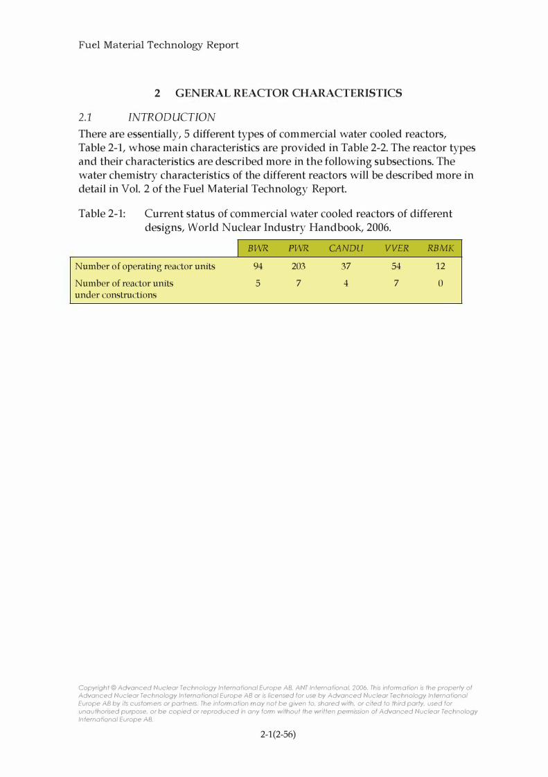
There are essentially, 5 different types of commercial water cooled reactors, Table 2-1, whose main characteristics are provided in Table 2-2. The reactor types and their characteristics are described more in the following subsections. The water chemistry characteristics of the different reactors will be described more in detail in Vol. 2 of the Fuel Material Technology Report.
Table 2-1: Current status of commercial water cooled reactors of different designs, World Nuclear Industry Handbook, 2006.
Number of operating reactor units
Number of reactor units under constructions
I BWR
94 5
PWR
203 7
CANDU
37 4
VVER
54 7
RBMK
12 o
Copyright © Advanced Nuclear Technology International Europe AB, ANT International, 2006. This information is the property of Advanced Nuclear Technology International Europe AB or is licensed for use by Advanced Nuclear Technology International Europe AB by its custom ers or partners. The inform ation may not be given to, shared with, or cited to third party, used for unauthorised purpose, or be copied or reproduced in any form without the written permission of Advanced Nuclear Technology International Europe AB.
2-1(2-56)

Fuel Material Technology Report
Table 2-2: Design parameters in water cooled reactors, Adamson et al., 2002.
Parameter Western type VVER CANDU
1.
2.
3.
4.
5.
6.
7.
8.
**
***
PWR (440flOOO) MW
Coolant Pressurized Pressurized Pressurized H2O H2O D20
Fuel assembly materials Zr-4, ZIRLO, EllO,E635 Zry-4 (pressure tube materials) DUPLEX,M5, (Zr2.5Nb)
MDA,NDA, Inconel, SS
Average power rating, 80-125 83/108 9-19 (kW /1)
Fast neutron flux, average, 6-9E13 5E13/7E13 1.5-2E12 n/cm2.s
Temperature,OC
Average coolant inlet 279-294 267/290 249-257
Average coolant outlet 313-329 298/320 293-305 Max cladding 0. D. 320-350 335/352 310 Steam mass content, %
System pressure, bar 155-158 125/165 96
Coolant flow, m/ s 3-6** 3.5/6 3-5
Coolant chemistry
Oxygen, ppb <0.05 <0.1 Hydrogen (D2),
ppm 2-4
cc/kg 25-50 30-60 (3-10) Boron (as boric acid), 0-2200 0-1400 -***
ppm
Li (as LiOH), ppm 0.5-3.5 0.05-0.6 0.6 K (as KOH), ppm - 5-20 NH3,ppm 6-30 NaOH,ppm 0.03-0.35
Variation from lower to upper part of the core and from plant to plant
Not in coolant but in moderator
BWR
Boiling H2O
Zry-2, Zry-4, Inconel, SS
40-57
4-7E13
272-278
280-300 285-305
7-14
70
2-5**
200-400
see section 2.3
-
--
RBMK
Boiling H2O
EllO,E635 (Zr2.5Nb)
5
1-2E13
270 284
290 14
67
3.7
<20 -
-
--
Copyright © Advanced Nuclear Technology International Europe AB, ANT International, 2006. This information is the property of Advanced Nuclear Technology International Europe AB or is licensed for use by Advanced Nuclear Technology International Europe AB by its custom ers or partners. The inform ation may not be given to, shared with, or cited to third party, used for unauthorised purpose, or be copied or reproduced in any form without the written permission of Advanced Nuclear Technology International Europe AB.
2-2(2-56)

Fuel Material Technology Report
2.2 PWR (ALFRED STRASSER)
Overview of the Primary Circuit
Components
The typical PWR reactor primary system shown on Figure 2-1 consists of the reactor vessel with its internals that support the fuel core, piping for the coolant recirculation system, a pressurizer, steam generators, pumps and valves. Auxiliary systems control the boron (B) and lithium (Li) additions and removals as well as a demineralizer, cleanup system for removal of impurities and a system to provide make-up water.
PRIMARY SYSTEM
I OF � LOOPS
89,700 GPH
Reactor Pressure Vessel COHTAINI.\EHT WALL //
and Primary Loop -- - -- - ---
TANK HEA TER
Secondary System (with Turbine and Generator)
TO WASTE
�I&-I� DI S POS A L
DEMI H.
WATER
Figure 2-1: Primary Coolant Systems for a Large PWR, modified figure according to Cohen, 1985.
TI HG
The primary system operates at a pressure of 2,250 psi (15.5 MPa) and the pressure
boundary consists of the reactor vessel, the recirculation piping, pressurizer, steam generator tubing and pumps as shown in Figure 2-2. There are heat transfer surfaces within the system that consist of the fuel cladding transferring heat to the primary coolant and the steam generator tubing transferring heat to the secondary coolant. The gamma heating of all the components within the reactor vessel is relatively minor, but is also removed by the coolant.
Copyright © Advanced Nuclear Technology International Europe AB, ANT International, 2006. This information is the property of Advanced Nuclear Technology International Europe AB or is licensed for use by Advanced Nuclear Technology International Europe AB by its custom ers or partners. The inform ation may not be given to, shared with, or cited to third party, used for unauthorised purpose, or be copied or reproduced in any form without the written permission of Advanced Nuclear Technology International Europe AB.
2-3(2-56)

Fuel Material Technology Report
STEAM GENERATOR
REACTOR COOLANT PUMP
NUCLEAR REACTOR VESSEL
Figure 2-2: PWR Primary System - Pressure Boundary, Westinghouse, 2005.
The structural components within the reactor include the upper and lower support plates, the core barrel, the core support components and others shown on Figure 2-3. Structural components are used in the pressurizer and steam generator as well, but not all are in contact with the primary coolant.
Copyright © Advanced Nuclear Technology International Europe AB, ANT International, 2006. This information is the property of Advanced Nuclear Technology International Europe AB or is licensed for use by Advanced Nuclear Technology International Europe AB by its custom ers or partners. The inform ation may not be given to, shared with, or cited to third party, used for unauthorised purpose, or be copied or reproduced in any form without the written permission of Advanced Nuclear Technology International Europe AB.
2-4(2-56)

Fuel Material Technology Report
CONTROL ROD
DRIVE SHAFT
UPPER
SUPPORT PL
INTERNALS
SUPPORT LED
CORE BARREL
UPPER CORE PLATE
REACTOR VESSEL
LOWER INSTRUMENTATION
GUIDE TUBE
BOTTOM SUPPORT
FORG I NG
RADIAL SUPPORT
TI E PLA
CONTROL ROO DRIVE
MECHANISM
THERMAL SLEEVE
CLOSURE HEAD
ASSEMBLY
HOLD-DOWN SHAR I NG
I NLET NOZZLE
FUEL ASSEMBLI ES
BAFFLE
FORMER
LOWER CORE PLATE
IRRADIATION
SPEC I MEN GU I DE
NEUTRON SHIELD PAD
CORE SUPPORT
COLUMNS
Figure 2-3: PWR Pressure Vessel Internals, Westinghouse, 2005.
The mechanical components consist of the pump and valves, some of which are quite complex.
Copyright © Advanced Nuclear Technology International Europe AR ANT International, 2006. This information is the property of Advanced Nuclear Technology International Europe AB or is licensed for use by Advanced Nuclear Technology International
Europe AB by its customers or partners. The information may not be given to, shared with, or cited to third party, used for unauthorised purpose, or be copied or reproduced in any form without the written permission of Advanced Nuclear Technology
International Europe AB.
2-5(2-56)
Fuel Material Technology Report
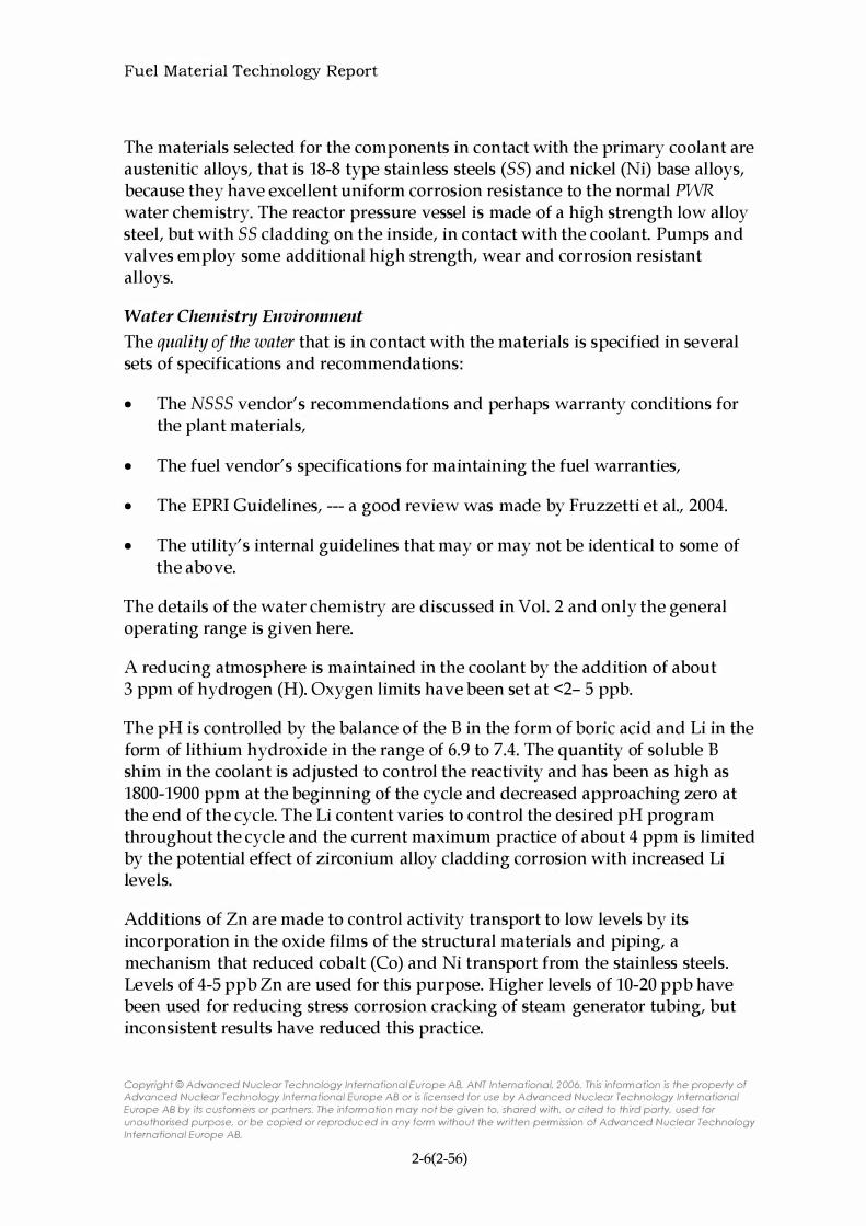
The materials selected for the components in contact with the primary coolant are austenitic alloys, that is 18-8 type stainless steels (55) and nickel (Ni) base alloys, because they have excellent uniform corrosion resistance to the normal PWR water chemistry. The reactor pressure vessel is made of a high strength low alloy steel, but with 55 cladding on the inside, in contact with the coolant. Pumps and valves em ploy some additional high strength, wear and corrosion resistant alloys.
Water Chemistry Environment The quality of the water that is in contact with the materials is specified in several sets of specifications and recommendations:
• The N555 vendor's recommendations and perhaps warranty conditions for the plant materials,
• The fuel vendor's specifications for maintaining the fuel warranties,
• The EPRI Guidelines, --- a good review was made by Fruzzetti et al., 2004.
• The utility's internal guidelines that may or may not be identical to some of the above.
The details of the water chemistry are discussed in Vol. 2 and only the general operating range is given here.
A reducing atmosphere is maintained in the coolant by the addition of about 3 ppm of hydrogen (H). Oxygen limits have been set at <2- 5 ppb.
The pH is controlled by the balance of the B in the form of boric acid and Li in the form of lithium hydroxide in the range of 6.9 to 7.4. The quantity of soluble B shim in the coolant is adjusted to control the reactivity and has been as high as 1800-1900 ppm at the beginning of the cycle and decreased approaching zero at the end of the cycle. The Li content varies to control the desired pH program throughout the cycle and the current maximum practice of about 4 ppm is limited by the potential effect of zirconium alloy cladding corrosion with increased Li levels.
Additions of Zn are made to control activity transport to low levels by its incorporation in the oxide films of the structural materials and piping, a mechanism that reduced cobalt (Co) and Ni transport from the stainless steels. Levels of 4-5 ppb Zn are used for this purpose. Higher levels of 10-20 ppb have been used for reducing stress corrosion cracking of steam generator tubing, but inconsistent results have reduced this practice.
Copyright © Advanced Nuclear Technology International Europe AB, ANT International, 2006. This information is the property of Advanced Nuclear Technology International Europe AB or is licensed for use by Advanced Nuclear Technology International Europe AB by its custom ers or partners. The inform ation may not be given to, shared with, or cited to third party, used for unauthorised purpose, or be copied or reproduced in any form without the written permission of Advanced Nuclear Technology International Europe AB.
2-6(2-56)

Fuel Material Technology Report
Other impurities are present for reasons other than the purposeful additions, such as:
• Fe, Ni, Cr, Co and potentially other metallic materials in solid or solution form, the product of uniform corrosion of the primary circuit materials,
• AI, Ca, Mg, 5i from contamination during maintenance work, impurities in the boric acid or Li additions or other sources such as Boroflex spent fuel racks,
• CI, F, 504, as well as oxidizing agents in ionic forms as the result of leakage from other systems, such as the demineralizers, pump seals, instrument lines, etc.
Many of these impurities were not known and taken into account at the time the plant materials were selected and perhaps even if known, the same materials may have been chosen. As a result of experience with these impurities new recommended limits have evolved, some of which are noted below.
The impurities with the most significant effect on plant materials corrosion, specifically SCC, are the halides (CI, F) and 504. The usual limit on halides is <1 ppb. A limit for 504 has not been set yet; in fact the analyses for this ion have been limited. Its appearance seems to occur primarily during shutdown.
Limits for the zeolites (AI, Ca, Mg) have been suggested as 5 ppb to prevent their deposit on the fuel and their potential densification of the crud that would increase the thermal resistance of the crud.
Limits on the metallic impurities have not been set; however the transport of Ni and Co is being controlled by Zn injection to limit activity transport, as noted above. The remaining elements will have an effect on fuel crud formation and cladding performance rather than have an effect on plant materials.
The temperature of the water is at its highest in the reactor core with core average
inlet temperatures of 542-559°F (284-293°C; 557-566K) and outlet temperatures of
602-619°F (318-327°C; 591-600). Hot assembly exit temperatures can go up to 636°F (336°C; 609K). The temperatures in the steam generator are lower and
produce steam in the range of 518-535°F (270-280°C; 543-553K).
Copyright © Advanced Nuclear Technology International Europe AB, ANT International, 2006. This information is the property of Advanced Nuclear Technology International Europe AB or is licensed for use by Advanced Nuclear Technology International Europe AB by its custom ers or partners. The inform ation may not be given to, shared with, or cited to third party, used for unauthorised purpose, or be copied or reproduced in any form without the written permission of Advanced Nuclear Technology International Europe AB.
2-7(2-56)

Fuel Material Technology Report
sec and IAsee: The major life limiting factor of primary circuit materials has been the stress corrosion cracking (See) and the irradiation assisted see (IASee) of austenitic alloys that include the 18-8 type stainless steels and the Ni base alloys. The see affects the components outside the reactor vessel, such as the piping and steam generator materials. The IASee obviously occurs within the reactor, including the vessel itself, where the components are exposed to radiation. The combined presence of four parameters at certain minimum levels, are responsible for see:
• Oxidizing species in the water,
• A stress and/ or strain in the material,
• An see sensitive microstructure,
• Extended reactor service time.
These and other factors that can enhance or mitigate susceptibility to see are discussed subsequently. They apply to both PWRs and BWRs even though in the BWRs the oxidizing species and water chemistry are different (pH 5.6-7.5 instead of 6.9-7.4), the coolant temperature is lower by about an average of 75°F (24°C; 24K) and there is extensive bulk boiling in the core instead of limited nucleate boiling.
Reactor Pressure Vessel (RPV) and Low Alloy Steels (LAS): The RPV consists of a welded steel shell and bottom enclosure with a bolted closure head assembly, Figure 2-3. The RPV has to contain the reactor pressurization of 2250 psia (15.5 MPa) and resist corrosion by the coolant; as the primary containment for the reactor core, it has to meet the highest reliability standards. The design criteria are met by a duplex material that consists of a low alloy steel (LAS) with high strength but insufficient uniform corrosion resistance, clad on the inside with stainless steel (SS) with somewhat lower strength, but excellent general corrosion resistance. The SS cladding can be prone to see and IAsec, but the LAS is much more resistant to Sec.
The LAS vessel is fabricated by forming and welding plates and the head is generally a forging usually made of the A533 alloy or equivalent. The compositions of LAS are given in Table 2-3. The stainless steel cladding, usually Type 308 SS is applied by weld overlay and approximately 5 mm (0.1969 in) thick. The compositions of SS are given in Table 2-4.
Copyright © Advanced Nuclear Technology International Europe AB, ANT International, 2006. This information is the property of Advanced Nuclear Technology International Europe AB or is licensed for use by Advanced Nuclear Technology International Europe AB by its custom ers or partners. The inform ation may not be given to, shared with, or cited to third party, used for unauthorised purpose, or be copied or reproduced in any form without the written permission of Advanced Nuclear Technology International Europe AB.
2-8(2-56)

Fuel Material Technology Report
Table 2-3: Low Alloy Steels (LAS).
Composition (wt. %) Other
AISI type Fe Cr Ni Mn Mo Si V C max. S max. constituents
Carbon (ferritic) steels
A106 Balance 0.3-1 . 1 0 . 1 0 min. 0.30 0.025 0.025 max (P) A501 Balance 4-6 1 .0 OAO-0.65 1 .0 0. 1 0 0.030 0.040 max (P) A508/2 Balance 0.35 0.7 0.7 0.6 0.05 0.27
A508/3 Balance 0.6 1 .3 0.52 0.05 0.20
A508/4 Balance 1 . 7 3.3 0.5 0.03 0.23
A508/5 Balance 1 . 7 3.3 0.5 0 . 1 5-0.30 0.1 0.23
A533 Balance 1 . 1 5-1 .50 OA5-0.60 0.05 0.25
Low-alloy (bainitic) steels
ICr-IMo-0.25V 96.07 1 . 0 0.85 1 .25 0.25 0.25 0.33
2;Cr-IMo (Grade 22) 95.7 2A2 OA9 0.98 0.28 -0 026 0.009 0.01 2 (P) and 0.05
(Cu) Nb in sta-
bilized version
Ni-Cr-MoV (A469 Class 8) Balance 1 .25-2.00 3. 25-4.00 0.60 0.30-0.60 0.1 5-0.30 0.05-0. 1 5 0.28 0.01 8 0 . 0 1 5 (P) Ni-Cr-MoV (A470 Class 8) Balance 0.90-1.50 0.75 1 . 00 1 00-1 50 0.1 5-0.35 0.20-0.30 0.25-0.35 0.01 8 0 . 0 1 5 (P) NCCr-MoV (A471 Class 8) Balance 0.75-2.00 2 00-4 00 0.70 0 20-0.70 0 . 1 5-0.35 0.05 0.28 0.01 5 0.01 5 (P)
Table 2-4: Composition of Stainless Steels.
Composition Percent
Designation Ni Cr Fe Mn C S Si P Mo Nb Ta
max max max max max max
304 8-1 1 1 8-20 bal 2.00 0.08 0.03 1 .00 0.04
304L 8-1 1 1 8-20 bal 2.00 0.03 0.03 1 .00 0.04
308 1 0-1 2 1 9-21 bal 2.00 0.08 0.03 1 .00 0.04
3 1 6 1 1 -1 4 1 6-1 8 bal 2.00 0.08 0.03 1 .00 0.03 2.0-3.0
3 1 6 L 1 1 -1 4 1 6-1 8 bal 2.00 0.03 0.03 1 .00 0.03
321 1 7-1 9 9-1 2 bal 0.50 0.08 0.03 1 .00 0.04 Ti = 5xC min.
347 9-1 3 1 7-20 bal 2.00 0.08 0.03 1 .00 0.03 10 x C
348 9-1 3 1 7-20 bal 2.00 0.08 0.03 1 .00 0.04 10 x C 0. 1 0
4 1 0 0 . 5 max. 1 7-20 bal 1 .00 0. 1 5 0.03 1 .00 0.04
Cu N b + Ta
1 7-4 P H 3-5 1 5-1 8 bal 1 .00 0.07 0.03 1 .00 0.04 3-5 0 . 1 5-0.45
The materials specified for the Westinghouse Advanced PWR (APIOOO) are listed in Table 2-5. The materials have not changed except that the low C version of Type 308 (0.03% C max.) is proposed instead of Type 308, Westinghouse, 2005.
Copyright © Advanced Nuclear Technology International Europe AB, ANT International, 2006. This information is the property of Advanced Nuclear Technology International Europe AB or is licensed for use by Advanced Nuclear Technology International Europe AB by its custom ers or partners. The inform ation may not be given to, shared with, or cited to third party, used for unauthorised purpose, or be copied or reproduced in any form without the written permission of Advanced Nuclear Technology International Europe AB.
2-9(2-56)

Fuel Material Technology Report
The major RPV issue is with the effect of radiation on the mechanical properties of the steel, such as the ductility, impact resistance and fracture toughness and is independent of water chemistry. The only water chemistry related questions arise in the event of the cracking or failure of the 55 liner that would allow ingress of the water to the LAS. Laboratory tests for see of the duplex structure have shown that cracks propagating through the 55 are arrested at the interface with the LAS. see crack growth has only been observed in laboratory tests in oxygenated BWR water with very high CI and S04 levels, Seifert et al., 2003.
Copyright © Advanced Nuclear Technology International Europe AB, ANT International, 2006. This information is the property of Advanced Nuclear Technology International Europe AB or is licensed for use by Advanced Nuclear Technology International Europe AB by its custom ers or partners. The inform ation may not be given to, shared with, or cited to third party, used for unauthorised purpose, or be copied or reproduced in any form without the written permission of Advanced Nuclear Technology International Europe AB.
2-10(2-56)

Fuel Material Technology Report
Table 2-5: Reactor Coolant Pressure Boundary Materials Specifications for the Westinghouse AP 1000.
Component Material Class, Grade, or Type
Reactor Vessel Components Head plates (other than core region) SA-533 or SA-508 GR B, CL I or CL 3
Shell courses SA-508 CL 3
Shell, flange, and nozzle forgings SA-508 CL 3
Nozzle safe ends SA- 1 82 F3 16LN
Appurtenances to the control rod drive SB- 167 or SA- 1 82 TP690 or F304LN,
mechanism (CRDM) F3 16LN
Instrumentation tube appurtenances, upper head SB- 167 or SA- 1 82, SA3 12, TP690 or F304LN,
SA376 F3 16LN
Closure studs SA-540 GR B23 or GR B24, CL 3
Monitor tubes and vent pipe SA-3 12 or SA-376 or TP304LN, TP3 1 6LN or
SB- 166, SB- 1 67 TP690
Cladding, buttering, and welds SFA 5 .4, 5 .9, 5 . 1 I , and 5 . 14 308L, 309L, ENiCrFe-7,
or ERNiCrFe-7
Pressure boundary welds Low alloy steel SFA 5 . 5 , 5 .23, 5 .28
Steam Generator Components Pressure plates SA-533 GR B, CL I
Pressure forgings (including nozzles and tube SA-508 CL 3a
sheet)
Nozzle safe ends SA- 1 82 F3 16LN
Channel heads SA-508 CL 3a
Tubes S B- 1 63 TP690TT
Cladding, buttering, and welds SFA 5 .4, 5 .9, 5 . 1 I , and 5 . 14 308L, 309L, ENiCrFe-7,
or ERNiCrFe-7
Pressure boundary welds Low alloy steel SFA 5 . 5 , 5 .23, 5 .28
Manway studs/nuts SA- 193, SA- 194 GR B7
Pressurizer Components Pressure plates SA-533 GR B, CL I
Pressure forgings SA-508 CL 3
Nozzle safe ends SA- 1 82 F3 16LN
Cladding, buttering, and welds SFA 5 .4, 5 .9, 5 . 1 I , and 5 . 14 308L, 309L, ENiCrFe-7,
or ERNiCrFe-7
Pressure boundary welds Low alloy steel SFA 5 . 5 , 5 .23, 5 .28
Manway studs/nuts SA- 193, SA- 194 GR B7
Reactor Coolant Pump Pressure forgings SA- 1 82 or SA-336 F304LN, F3 16LN
Pressure casting SA-35 I or SA-352 CF3A
Tube and pipe SA-2 1 3 ; SA-376 or SA-3 12 TP304LN, TP3 16LN
Pressure plates SA-240 304LN, 3 16LN
Closure bolting SA- 193 or SA-540 GR B7 or GR B24, CL 4
Pressure boundary welds Low alloy steel SFA 5 . 5 , 5 .23, 5 .28
Copyright © Advanced Nuclear Technology International Europe AB. ANT International. 2006. This information i s the property of Advanced Nuclear Technology International Europe AB or is licensed for use by Advanced Nuclear Technology International Europe AB by its custom ers or partners. The inform ation may not be given to. shared with. or cited to third party. used for unauthorised purpose. or be copied or reproduced in any form without the written permission of Advanced Nuclear Technology International Europe AB.
2-11(2-56)
Fuel Material Technology Report
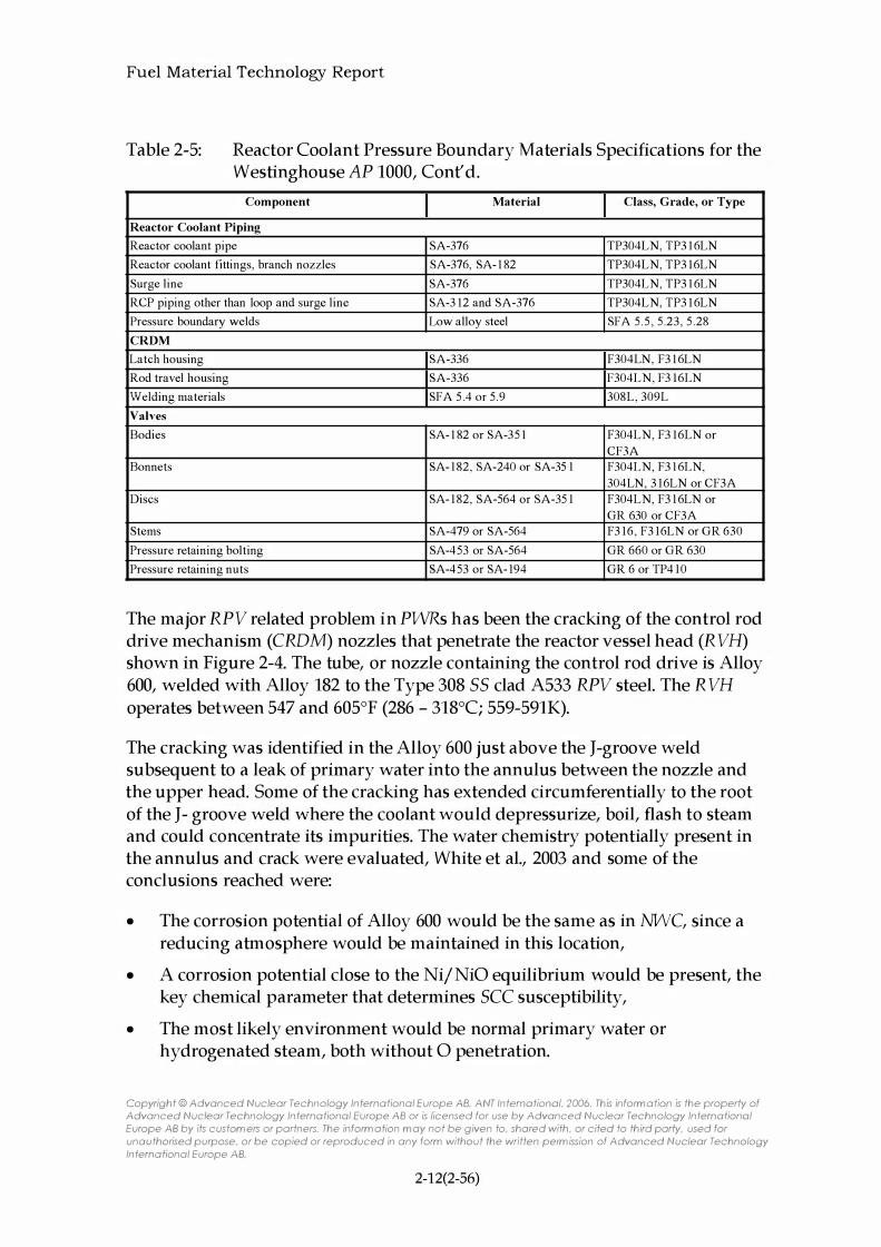
Table 2-5: Reactor Coolant Pressure Boundary Materials Specifications for the Westinghouse AP 1000, Cont'd.
Component Material Class, Grade, or Type
Reactor Coolant Piping Reactor coolant pipe SA-376 TP304LN, TP3 1 6LN
Reactor coolant fittings, branch nozzles SA-376, SA- 1 82 TP304LN, TP3 16LN
Surge line SA-376 TP304LN, TP3 1 6LN
RCP piping other than loop and surge line SA-3 12 and SA-376 TP304LN, TP3 1 6LN
Pressure boundary welds Low alloy steel SFA 5 . 5 , 5 .23, 5 .28
CRDM Latch housing SA-336 F304LN, F3 1 6LN
Rod travel housing SA-336 F304LN, F3 16LN
Welding materials SFA 5 .4 or 5 .9 308L, 309L
Valves Bodies SA- 1 82 or SA-35 1 F304LN, F3 16LN or
CF3A
Bonnets SA- 1 82, SA-240 or SA-35 I F304LN, F3 1 6LN,
304LN, 3 16LN or CF3A
Discs SA- 1 82, SA-564 or SA-35 I F304LN, F3 1 6LN or
GR 630 or CF3A
Stems SA-479 or SA-564 F3 16, F3 16LN or GR 630
Pressure retaining bolting SA-453 or SA-564 GR 660 or GR 630
Pressure retaining nuts SA-453 or SA- 194 GR 6 or TP4 10
The major RPV related problem in PWRs has been the cracking of the control rod drive mechanism (CRDM) nozzles that penetrate the reactor vessel head (RVH) shown in Figure 2-4. The tube, or nozzle containing the control rod drive is Alloy 600, welded with Alloy 182 to the Type 308 55 clad A533 RPV steel. The RVH operates between 547 and 605°F (286 - 318°C; 559-591K).
The cracking was identified in the Alloy 600 just above the J-groove weld subsequent to a leak of primary water into the annulus between the nozzle and the upper head. Some of the cracking has extended circumferentially to the root of the J- groove weld where the coolant would depressurize, boil, flash to steam and could concentrate its impurities. The water chemistry potentially present in the annulus and crack were evaluated, White et al., 2003 and some of the conclusions reached were:
• The corrosion potential of Alloy 600 would be the same as in NWC, since a reducing atmosphere would be maintained in this location,
• A corrosion potential close to the Nij NiO equilibrium would be present, the key chemical parameter that determines SCC susceptibility,
• The most likely environment would be normal primary water or hydrogenated steam, both without 0 penetration.
Copyright © Advanced Nuclear Technology International Europe AB. ANT International. 2006. This information is the property of Advanced Nuclear Technology International Europe AB or is licensed for use by Advanced Nuclear Technology International Europe AB by its custom ers or partners. The inform ation may not be given to. shared with. or cited to third party. used for unauthorised purpose. or be copied or reproduced in any form without the written permission of Advanced Nuclear Technology International Europe AB.
2-12(2-56)

Fuel Material Technology Report
The reactor heads have been and are being replaced to correct the problem and the replacements are substituting Alloy 690 for 600 and the weld Alloy 182 may be replaced by Alloy 152 for improved sec resistance.
1 . Craze cracks on ID surface 2. Circ crack below weld 3 . Deep axial crack through weld 4. Shallow a'Cial crack at nozzle OD 5. Deep circ crack above weld 6. Deep axial crack on ID surface
Figure 2-4: Location Of Typical PWR Reactor Vessel Closure Head Nozzle pwsee (Alloy 600 eRDM Nozzle Shown with Alloy 182 J-groove Weld and Buttering, Low Alloy Steel Shell, and Stainless Steel Cladding), White et al., 2003.
An extensive international program involved both analytical and experimental evaluation of the crack growth rates as well as the evaluation of plant experience in the US and Europe. The objective was to develop a model for eGR and life expectancies of cracked Alloy 600 nozzles and other Alloy 600 components in PWRs with the exception of the thin walled steam generator tubes, White et al., 2003.
Copyright © Advanced Nuclear Technology International Europe AB, ANT International, 2006. This information is the property of Advanced Nuclear Technology International Europe AB or is licensed for use by Advanced Nuclear Technology International Europe AB by its custom ers or partners. The inform ation may not be given to, shared with, or cited to third party, used for unauthorised purpose, or be copied or reproduced in any form without the written permission of Advanced Nuclear Technology International Europe AB.
2-13(2-56)

Fuel Material Technology Report
The high sensitivity of crack growth rates to temperature was the reason for standardizing and normalizing all data at 327°C (617°F; 600K), the most likely temperature in this region. The large heat to heat scatter and the limited data per heat make the interpretation of the dependence of the CGR on the stress intensity factor difficult and for those manipulations I leave the reader to the reference. The curve for CGR vs. the stress intensity factor, K, developed by the EPRI Material Reliability Program (MRP) with much of the data base is shown in Figure 2-5.
I .E-09 ..,.-----,----;---...,-----,;-----;---...,---;----,r---------,
� � I .E-t O -1---+---� � .. � .c .. � Q c:s I .E- L L
..::.:: � � t. U
I .E - L 2 +----111----+---+--+---+----..,1----+----1
o 1 0 20 30 40 50 60 70 80
Stress Intensity Factor, K (MPa..Jm)
o MRl' Lab CGR Database ( 1 58
points)
[J Cook2 #75 Length Increase
• Cook2 #75 Depth Increase
Figure 2-5: Screened Laboratory Data For Alloy 600 With The MRP Crack Growth Curve, The Modified Scott Curve, and CGR Data For Cook 2 Nozzle #75, White et al., 2003.
Reactor Internals and Recirculation Piping: The major components of the reactor internals, shown in Figure 2-3, include the core barrel, the upper and lower support plates and their associated assemblies. The functions of the components are both hydraulic, to contain and direct the coolant flow and structural, to support the core at the appropriate spacing of the fuel elements and control elements. All of the components are made of austenitic Type 300 SS with compositions shown on Table 2-4.
Copyright © Advanced Nuclear Technology International Europe AB, ANT International, 2006. This information is the property of Advanced Nuclear Technology International Europe AB or is licensed for use by Advanced Nuclear Technology International Europe AB by its custom ers or partners. The inform ation may not be given to, shared with, or cited to third party, used for unauthorised purpose, or be copied or reproduced in any form without the written permission of Advanced Nuclear Technology International Europe AB.
2-14(2-56)

Fuel Material Technology Report
3 FUEL ASSEMBLY DESIGN
3.1 GENERAL OUTLINE OF FUEL ASSEMBLY DESIGNS AND FUNCTIONS
3.1.1 PWR and BWR (Alfred Strasser and Peter Rudling)
There is a wide variety of different types of fuel assemblies for Light Water Reactors, LWRs. The fuel rod array for BWRs was initially 7x7 but there has been a trend over the years to increase the number of Fuel Assembly, FA, rods and today most FA designs are either of 9x9 or lOXlO square configuration design. The driving force for this trend was to reduce the Linear Heat Generation Rate, LHGR, which resulted in a number of fuel performance benefits such as lower Fission Gas Release, FGR, and increased Pellet Cladding Interaction, PCI, margins. However, to increase utility competitiveness, the LHGRs of 9x9 and lOxlO FA has successively been increased, and peak LHGRs are today almost comparable to that of the 7x7 and 8x8 older designs.
Also for PWRs there has been a trend to greater subdivision of fuel rods, e.g. from Westinghouse l5x15 to l7x17 design. However to accomplish this one had to go to a new reactor design this since the PWRs do not have the same flexibility with core internals and control rods as do BWRs. Figure 3-1 shows the current PWR fuel rod array designs.
Copyright © Advanced Nuclear Technology International Europe AB, ANT International, 2006. This information is the property of Advanced Nuclear Technology International Europe AB or is licensed for use by Advanced Nuclear Technology International Europe AB by its custom ers or partners. The inform ation may not be given to, shared with, or cited to third party, used for unauthorised purpose, or be copied or reproduced in any form without the written permission of Advanced Nuclear Technology International Europe AB.
3-1(3-115)

Fuel Material Technology Report
00000000000000 00000000000000 00000000000000 00000000000000 00000000000000 00000000000000 000000.0000000
14x14 00000000000000 00000000000000 00000000000000 00000000000000 00000000000000 00000000000000 00000000000000
000000000000000 000000000000000 000000000000000 000000000000000 000000000000000 000000000000000 000000000000000
15x15 0000000.0000000 000000000000000 000000000000000 000000000000000 000000000000000 000000000000000 000000000000000 000000000000000
0000000000000000 0000000000000000 0000000000000000 0000000000000000 0000000000000000 0000000000000000 0000000000000000
16x16 0000000.00000000 0000000000000000 0000000000000000 0000000000000000 0000000000000000 0000000000000000 0000000000000000 0000000000000000 0000000000000000
00000000000000000 00000000000000000 00000000000000000 00000000000000000 00000000000000000 00000000000000000 00000000000000000 00000000000000000 00000000.00000000 00000000000000000 00000000000000000 00000000000000000 00000000000000000 00000000000000000 00000000000000000 00000000000000000 00000000000000000
000000000000000000 000000000000000000 000000000000000000 000000000000000000 000000000000000000 000000000000000000 000000000000000000 000000000000000000 00000000.000000000 000000000000000000 000000000000000000 000000000000000000 000000000000000000 000000000000000000 000000000000000000 000000000000000000 000000000000000000 000000000000000000
17x17
18x18
Figure 3-1: Layouts of different PWR fuel assembly design, Rods marked with yellow colour are guide tubes into which the control rod cluster is inserted. The position marked by a red filled circle is the instrument tube position.
Copyright © Advanced Nuclear Technology International Europe AB, ANT International, 2006. This information is the property of Advanced Nuclear Technology International Europe AB or is licensed for use by Advanced Nuclear Technology International Europe AB by its custom ers or partners. The inform ation may not be given to, shared with, or cited to third party, used for unauthorised purpose, or be copied or reproduced in any form without the written permission of Advanced Nuclear Technology International Europe AB.
3-2(3-115)

Fuel Material Technology Report
In most PWRs, the assemblies are positioned in the core by bottom and top fittings, and the lateral clearances are restricted by the assembly-to-assembly contacts at the spacer-grid levels. Furthermore, the control rods consist of rod cluster control assemblies, RCCAs, the poison part of which moves into guide thimbles (or guide tubes). These guide thimbles are an integral part of the assembly structure.
In all BWRs the assemblies are enclosed in "fuel channels" surrounding the assemblies and between which the blades of the control rods moves.
Irrespective of the many possible different shapes, sizes and configurations, the common FA design requirements are:
• maintain proper positioning of the fuel rods under normal operating conditions and in design basis accidents (e.g. seismic effects, LOCA, RIA)
• permit handling capability before and after irradiation.
Figure 3-2 and Figure 3-3 show a typical BWR and PWR FA, respectively. Also, the different fuel assembly components are shown and the material selections for these components are provided. The reason for the difference in structural material selection is that in general the most inexpensive material is chosen for a specific component that yields the lowest cost to produce the component while ensuring adequate performance during normal operation and accidents.
Copyright © Advanced Nuclear Technology International Europe AB, ANT International, 2006. This information is the property of Advanced Nuclear Technology International Europe AB or is licensed for use by Advanced Nuclear Technology International Europe AB by its custom ers or partners. The inform ation may not be given to, shared with, or cited to third party, used for unauthorised purpose, or be copied or reproduced in any form without the written permission of Advanced Nuclear Technology International Europe AB.
3-3(3-115)

Fuel Material Technology Report
4 FUEL ROD, ASSEMBLY AND PRESSURE TUBE PERFORMANCE
4.1 FUEL ROD AND ASSEMBLY (AL STRASSER AND PETER RUDLING)
The performance of the critical fuel components is the result of a complex interaction of a large number of variables that challenge the evaluation of the mechanisms in progress and the prediction of their behavior at extended and more severe conditions. The technologies involved include just about every aspect of materials science imaginable: properties of materials, metallurgy, structural mechanics, coolant chemistry, physical chemistry, and their basic mechanisms just to mention a few examples. In addition, exposure to radiation changes all of the physical properties and processes: the properties of the structural materials and of the coolant change, transformations in structure and composition occur in all the materials (true alchemy!), and these processes occur in a non-homogeneous and non-equilibrium manner throughout the core.
A study of the materials' performance is difficult even outside the reactor's radiation field and provides limited data. Test reactors offer a good tool for evaluating a limited number of variables and mechanisms and have provided some valuable data; however, the operation and use of these reactors is expensive. The final performance evaluation is in the power reactor itself since it provides all the variables of importance; however, the lack of instrumentation, the inability to control testing time, as well as the difficulty of separating variables makes interpretation of ongoing processes difficult. The final evaluation of new materials and fuels for high burnups progresses necessarily through the stages mentioned: ex-reactor testing, test reactor evaluation of samples, power reactor evaluation of samples or full fuel assemblies.
The degree of success achieved in fuel performance to date has been remarkable considering the lengthy evaluation process required and the tough conditions the fuel assembly is exposed to in service.
During normal operation the following materialj component properties have a major impact on fuel performance and may limit the discharged burnup21 :
• Corrosion of zirconium alloy cladding and the water chemistry parameters that enhance corrosion,
• Dimensional changes of zirconium alloy components,
• Stresses that challenge zirconium alloy ductility and the effect of hydrogen (H) pickup and redistribution as it affects ductility,
21 The product of irradiation time (in days) and power generated by the fuel (in MW)
Copyright © Advanced Nuclear Technology International Europe AB, ANT International, 2006. This information is the property of Advanced Nuclear Technology International Europe AB or is licensed for use by Advanced Nuclear Technology International Europe AB by its custom ers or partners. The inform ation may not be given to, shared with, or cited to third party, used for unauthorised purpose, or be copied or reproduced in any form without the written permission of Advanced Nuclear Technology International Europe AB.
4-1(4-57)

Fuel Material Technology Report
• Fuel rod internal pressure,
• Pellet-cladding interactions (PCI) and pellet-cladding mechanical interactions (PCMI),
• Grid-to-rod fretting
• Fuel rod collapse
The list has not changed significantly in over a decade, Goldstein et al., 1990. The only items above that have posed limits to extending burnups have been corrosion and dimensional changes in both BWRs and PWRs and PCI in BWRs, more details are provided in the ZIRAT-8/ IZNA-3 Special Topics Report on High Burnup Fuel
Issues, Adamson et al., 2003(b) and Adamson et al., 2004. Improved materials and operating procedures have been able to exceed all of these limits and have not reached new limits within current operating strategies.
Poor fuel performance may result in fuel failures, Figure 4-1 to Figure 4-4 and Table 4-1, Table 4-2 and Table 4-3
Other material performance problems have occurred in reactors such as:
• Manufacturing defects- An example is the internal hydriding of fuel rods due to moisture in the pellets.
• Debris and baffle jetting fretting defects
• Degradation of failed fuel
The subsections to follow summarize the major parameters that influence the potential burnup limitations and the current and potential fixes that can extend the limits. The detailed discussion of their technology and current experience base are discussed in Vol. 2.
Copyright © Advanced Nuclear Technology International Europe AB, ANT International, 2006. This information is the property of Advanced Nuclear Technology International Europe AB or is licensed for use by Advanced Nuclear Technology International Europe AB by its custom ers or partners. The inform ation may not be given to, shared with, or cited to third party, used for unauthorised purpose, or be copied or reproduced in any form without the written permission of Advanced Nuclear Technology International Europe AB.
4-2(4-57)

Fuel Material Technology Report
Figure 4-1:
1 40
1 20
1 00 en ., :c E .. en 80 en ..: .., � ;;; u.. '0 ... 60 ., .c E ::> z
40
20
a
Fretting spring b reaksg e
Debris
Fretting (other causes)
Siemens (now AREVA NP) PWR Fuel Rod Failure Causes 1992-2001, Klinger et al., 2002.
o Crud/corrosion
D Gfi d- retting o Debris
. I'v\allufac uri n g
o APSRlPCI suspect
• Unknol'.11/no t i
1 990 199 1 1992 1993 1994 1995 1 996 1997 1 998 1999 2000 2001 2002 2003 2004P
Figure 4-2:
Year
Trend in US PWR failure root causes (2004 results are incomplete), Yang et al., 2004.
Copyright © Advanced Nuclear Technology International Europe AB, ANT International, 2006. This information is the property of Advanced Nuclear Technology International Europe AB or is licensed for use by Advanced Nuclear Technology International Europe AB by its custom ers or partners. The inform ation may not be given to, shared with, or cited to third party, used for unauthorised purpose, or be copied or reproduced in any form without the written permission of Advanced Nuclear Technology International Europe AB.
4-3(4-57)

Fuel Material Technology Report
5 FUEL PERFORMANCE CODES (PETER RUDLING)
5.1 INTRODUCTION
Analytical methods (computer codes) are used in safety analysis, either as standalone codes or in a coupled manner. These codes must include relevant models that accurately describes the performance of the fuel during normal operation and during design basis accident such as a LOCA and RIA at all burnup levels. The computer codes are of different types as described below.
Steady state fuel rod codes: The steady-state single-rod codes, like FRAPCON, COMETHE, TRANSURANUS, METEOR and TOUTATIS calculate thermal quantities such as the fuel rod radial temperature profile and fission gas release to the fuel rod gap, and mechanical quantities such as creep deformation and irradiation growth.
Results are used for many purposes like axial clearance between rods and end fittings, fuel rod internal gas pressure to compare with system pressure, cladding oxide thickness to compare with established limits or to initiate transient calculations (LOCA and RIA), stored fuel energy for LOCA analysis and fission gas repartition between grains, grain boundaries and porosities for RIA fuel failure mechanisms studies.
These codes consist of numerous models and correlations to describe gap conductance, material properties such as thermal conductivity and specific heat, radial power profiles, stress-strain equations, mechanical properties, creep properties, fuel-swelling, fuel-densification, waterside corrosion, and hydrogen absorption.
Transient fuel rod codes: The single-rod transient codes, like FALCON/FREY, FRAPTRAN, and SCANAIR also calculate thermal quantities and mechanical quantities. The range of models and correlations included in these codes is quite similar to that for the steady-state codes. The major differences between transient and the steady-state codes are:
• The steady-state codes do not include transient heat-transfer terms in their solution equations; and
• The transient codes do not include long-term phenomena like creep.
However, the transient codes need to incorporate models, correlations, and properties for cladding plastic stress-strain behaviour at elevated temperatures, effects of annealing, behaviour of oxides and hydrides during temperature ramps, phase changes, and large cladding deformations such as ballooning.
Copyright © Advanced Nuclear Technology International Europe AB, ANT International, 2006. This information is the property of Advanced Nuclear Technology International Europe AB or is licensed for use by Advanced Nuclear Technology International Europe AB by its custom ers or partners. The inform ation may not be given to, shared with, or cited to third party, used for unauthorised purpose, or be copied or reproduced in any form without the written permission of Advanced Nuclear Technology International Europe AB.
5-1(5-14)

Fuel Material Technology Report
The transient codes are used for analysing fuel rod response to transients and accidents like RIA and LOCA and may include failure models.
The RELAP5/Mod3.3 was developed as a best estimate transient code of light water reactor coolant systems during postulated accidents. The code models the coupled behaviour of the reactor coolant system and the core for operational transients such as anticipated transient without scram.
The consolidated code TRAC-M, is the NRC result to joint in a single code the capabilities and models of TRAC-P, TRAC-BF1 and RELAP, with the goal to reduce the maintenance costs of the previous structure based in three different codes and to achieve a better performance of the resulting code.
Reactor static codes - To generate the neutronic cross sections used in the multidimensional kinetic codes, instantaneous thermal-hydraulic parameters such as fuel and moderator temperatures reactor static codes are applied.
Reactor kinetics codes - Reactor kinetics codes, e.g. RAMONA, P ARCS, SIMULATE-K, CORETRAN and SAPHYR calculates fuel assembly averaged neutron flux and power during reactor core power transients. A point-kinetics model may be used to analyse a whole core event such as coolant temperature changes in a PWR. However, localised events such as rod ejection in a PWR or control rod drop in a BWR require multidimensional neutron kinetic analysis.
Thermal-hydraulic, T-H, codes - Codes like TRAC, RELAP, CATHARE, ATHLET and RETRAN are T-H- codes that calculates flow, temperature and pressure during normal operation and transients. In most cases these codes contain point kinetics models to model the reactor power in PWR and 1-D kinetics models for BWRs. These codes may also be coupled with a 3-D neutronic kinetics code. The T-H codes have typically at least one coolant channel that models a few individual fuel rods. The fuel rod models in the T-H codes will normally include heat transfer correlations between the coolant and the fuel rod cladding, the pellet-clad gap for gap conductance, an average value for thermal conductivity and heat capacity. For LOCA analysis, these codes also contain normally ballooning, burst and oxidation models.
Subchannel codes: These codes are used to analyse the coolant flow distribution within the fuel assembly. These codes normally include a 3-D model for twophase flow, 1-D models of the different fuel rods and detailed models for the heat transfer between the cladding and the coolant. These codes are used to calculate the critical heat flux to demonstrate that the Departure of Nuclear Boiling Ratio/Critical Power Ratio, DNBR/CPR, requirements are met.
Copyright © Advanced Nuclear Technology International Europe AB, ANT International, 2006. This information is the property of Advanced Nuclear Technology International Europe AB or is licensed for use by Advanced Nuclear Technology International Europe AB by its custom ers or partners. The inform ation may not be given to, shared with, or cited to third party, used for unauthorised purpose, or be copied or reproduced in any form without the written permission of Advanced Nuclear Technology International Europe AB.
5-2(5-14)

Fuel Material Technology Report
5.2 FUEL ROD STATIC AND TRANSIENT CODES
To ensure that fuel does not fail during normal operation, anticipated operational occurrences and that coolability is maintained during postulated accidents (such as LOCA and RIA), fuel design criteria (such as maximum rod internal pressure, peak fuel temperature, boiling crises not allowed, peak cladding temperature during LOCA, etc.) are specified by the Regulators, see Vol. 2 for more details. In most countries the Regulators are applying the same criteria as USNRC.
The fuel vendors are using fuel performance codes to determine the thermal limits on their fuel design that will ensure that the fuel design criteria are met, Figure 5-1. For each fuel design criteria there will be a thermal limit varying with burnup and the most limiting thermal limit will establish the operating regime of the fuel design, see Figure 5-2.
Also, cycle specific analysis are done either by the fuel vendor or the utility to ensure that the core loading is appropriate and that thermal limits will not be exceeded. Finally, the utility must supervise the core with the core monitoring systems to ensure that thermal limits provided by the fuel vendors for their fuel is not exceeded.
r Manufactuming Modell
parameters parameters
,�,-, �,-, Rod power
I Rod power I prior to
Normal hIstOry LOCA event -
operation I 1 I I , , ,
Fuel performance code
CARO-E
- - - - - - - - - - - - - - - - - - - - - - - - - - - - - - - - - - - - - - - -
Transient LOCA code I RELAP I BETHY-AX/AZ I output
LOCA
� + I Rod defected (yes/no) I
Figure 5-1: Schematics showing the process of establishment of thermal limits, modified figure according to Heins, 2004.
Copyright © Advanced Nuclear Technology International Europe AB, ANT International, 2006. This information is the property of Advanced Nuclear Technology International Europe AB or is licensed for use by Advanced Nuclear Technology International Europe AB by its custom ers or partners. The inform ation may not be given to, shared with, or cited to third party, used for unauthorised purpose, or be copied or reproduced in any form without the written permission of Advanced Nuclear Technology International Europe AB.
5-3(5-14)

Fuel Material Technology Report
6 MANUFACTURING OF PRESSURES TUBES IN CANDU AND RBMK REACTORS (BRIAN COX)
Although initial studies focussed on (a+ jJ) quenching (�880°C) or ,B-quenching
(�960°C) of the already extruded tubes, the use of "heat-treated" tubes was ultimately not pursued either in Russia or in Canada. However, several reactors were built with heat-treated tubes. These were the Japanese prototype reactor "Fugen"; the CANDU-BLW prototype in Gentilly-l and the 180 MWe Karachi Nuclear Power Plant (KANUPP). Of these only the last is still operating. In addition a few heat-treated Zr-2.5Nb tubes were installed in other prototype reactors - 4 in SGHWR; (1 heat-treated + 1 cold-worked tube) in the 25 MWe CANDU prototype NPD. Three in-reactor loop tubes were also exposed in test reactors NRX and NRU. The tubes in Gentilly-l saw very little irradiation exposure, but comparisons of the properties of the others have been published, Chow et al., 1996, Koike & Asada, 1988 and Koike et al., 1994. For present purposes only the comparison of the corrosion behaviour is appropriate, Figure 6-1. Although the corrosion of heat-treated tubes appears to be better than that of cold-worked tubes (base on this limited evidence), the hydrogen uptakes all appear to fall in the same scatter band, Figure 6-2. The low deuterium contents of the NPD tubes may reflect the comparatively low temperatures and fluences in this reactor.
The Russian and Canadian fabrication routes for cold-worked Zr-2.5Nb pressure
tubes are very similar. Both comprise an initial ,B-quench of the billet prior to extrusion in the (a+jJ) phase field (780-850°C), Figure 6-3, Cheadle et al., 1974, followed by a similar cold-working to final size (typically 25-28% recrystallised, Shishov et al., 1996. Only small differences in billet shapes and sizes and extrusion ratios distinguish the two products. The Canadian ingots are now quadruple melted compared to double melting for the Russians. The quadruple melting reduces impurities such as H, C and CI in the initial ingot. This has resulted in a major improvement in fracture toughness, Figure 6-4, Coleman et al., 1996, and has reduced the average initial hydrogen content
Copyright © Advanced Nuclear Technology International Europe AB, ANT International, 2006. This information is the property of Advanced Nuclear Technology International Europe AB or is licensed for use by Advanced Nuclear Technology International Europe AB by its custom ers or partners. The inform ation may not be given to, shared with, or cited to third party, used for unauthorised purpose, or be copied or reproduced in any form without the written permission of Advanced Nuclear Technology International Europe AB.
6-1(6-12)
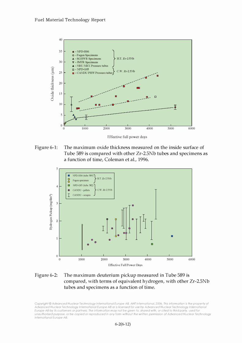
Fuel Material Technology Report
6' :::l.. '-./ en en (1) ] o :B
40 r-------------------------------------------------------�
35 30 25 20
o - Fugen Specimens • - NPD-H06 } /j. - SGHWR Specimens H.T. Zr-2.SNb
V - JMTR Specimens
... - NRU/NRX Pressure tubes [J - NPD-GOS
} • - CANDU PHW Pressure tubes C.W. Zr-2.SNb
•
-
.-1:J 1 5 . " " . ' ):1
o
Figure 6-1:
5 4
�
! 3 g !
u i:l: ::: v 2 bJl 0 I-< .,,; £'
0 Figure 6-2:
10 : J:�--�:y���'='�'-�'---------------------'--'------.-- _[J ---I
0
o 1000 2000 3000 4000 5000 6000 Effective full power days
The maximum oxide thickness measured on the inside surface of Tube 589 is compared with other Zr-2.5Nb tubes and specimens as a function of time, Coleman et al., 1996.
• NPD-H06 (tube 589)} g H.T. Zr-2.5Nb
Fugen specimen
[J NPD-G05 (tube 582) } • CANDU - pellets c.w. Zr-2.5Nb
I CANDU - scrapes
d · I. • • • • 1000 2000
• II ·
I PI I • []
3000 4000 Effective Full Power Days
•
5000 6000 The maximum deuterium pickup measured in Tube 589 is compared, with terms of equivalent hydrogen, with other Zr-2.5Nb tubes and specimens as a function of time.
Copyright © Advanced Nuclear Technology International Europe AB, ANT International, 2006. This information is the property of Advanced Nuclear Technology International Europe AB or is licensed for use by Advanced Nuclear Technology International Europe AB by its custom ers or partners. The inform ation may not be given to, shared with, or cited to third party, used for unauthorised purpose, or be copied or reproduced in any form without the written permission of Advanced Nuclear Technology International Europe AB.
6-2(6-12)

Fuel Material Technology Report
Diagrammatic represen tation
of the flow l i nes
E. D.
SAMPLE A
ED is EXTRUSION DIR8:TlON RQ is RADI A L DIRECnO N C.D.is CIRCUMFERENTIJ!L
DIRECTION
ED.
)u:id��==�:!!l!E�==r EXTRUDED '. TU BE
MANDREL '
'--'--�[EJ: EXT� DIRECTION
Position of the texture measurements on the
partially ex truded billet
E.D.
SAM PLE B D LESS THAN RANDOM
� 1 - 2 T I M ES RANDOM
1SS1 2 -3 T I M ES RANDOM
E!11 3-4 TI MES R'ANDOM
E .
� 4-5 TI M E S R ANDOM
Figure 6-3: The (0002) pole figures of samples A, B, C and D from the partially extruded billet.
Copyright © Advanced Nuclear Technology International Europe AB, ANT International, 2006. This information is the property of Advanced Nuclear Technology International Europe AB or is licensed for use by Advanced Nuclear Technology International Europe AB by its custom ers or partners. The inform ation may not be given to, shared with, or cited to third party, used for unauthorised purpose, or be copied or reproduced in any form without the written permission of Advanced Nuclear Technology International Europe AB.
6-3(6-12)
Fuel Material Technology Report
7 MANUFACTURING OF BWR AND PWR FUEL MATERIALS
7.1 CURRENT INDUSTRY SETUP (AL STRASSER AND PETER RUDLING)
The original number of fuel suppliers has been reduced by a series of corporate mergers and is currently dominated by a few large fuel manufacturers such as British Nuclear Fuel/Westinghouse), GNF, Framatome ANP and TVEL, Table 7-1. The table also indicates that there exists a large overcapacity to produce nuclear fuel today.
The ownerships and organisation structure has undergone large changes for GNF, Framatome ANP and Westinghouse, see Figure 7-1 to Figure 7-3. In addition, during the period when this document was being written, the Westinghouse organization has been purchased by Toshiba.
Copyright © Advanced Nuclear Technology International Europe AB, ANT International, 2006. This information is the property of Advanced Nuclear Technology International Europe AB or is licensed for use by Advanced Nuclear Technology International Europe AB by its custom ers or partners. The inform ation may not be given to, shared with, or cited to third party, used for unauthorised purpose, or be copied or reproduced in any form without the written permission of Advanced Nuclear Technology International Europe AB.
7-1(7-97)

Fuel Material Technology Report
Table 7-1: Fuel suppliers and their fuel fabrication plants (worldwide list, capacities, etc.), World Nuclear Industry Handbook, 2003.
Facility Capacity Annual production Operator Product Europe
Dessel, Belgium 40 tHM34/y 38 tHM Belgonucleaire LWR/MOX 400 tHM/y NA* F ANP (old FBFC) PWR
Karlstein, Germany 400tU/y NA FANP GmbH Components only, no pellet capacity
Lingen, Germany 550 tHM/y 450 FANP GmbH BWR; PWR Novosibirsk 1000 tU/y NA TVEL VVER assemblies only
Ust-Kamenogorsk 2650 tU/y NA TVEL VVER Elektrostal, Russia 570 t/y 570 t/y Mashinostroitelny RBlv1K fuel assemblies
700 t/y 230 t/y Mashinostroitelny VVER fuel assemblies
Cadarache, France 15 tHM/y NA Cogema LWR MOX Melox, France 120 tHM/y NA Melox LWR MOX Pierrelate, France 400 tHM/y NA FANP PWR, LWR MOX Romans, France 750 tHM/y NA FANP PWR Juzbado, Spain 300 tHM/y 234 tHM ENUSA BWR; PWR Vaster as, Sweden 600 tU02/y 317 tUOz Westinghouse Sweden BWR; PWR fuel components
NOFC Springfields, UK 330 tUfy 37 tU BNFL PWR MDR Sellafield, UK 8 tU/y NA BNFL MOX
North and South America Ezeizd, Argentina 300tU/y 160 tU NASA PHWR
Resende, Brazil 100 tHM/y 16 tHM Industrias Nucleares do Brasil PWR Columbia, USA 1200 tHM/y NA Westinghouse PWR Lynchburg, USA 400 tHM/y 232 t FBFC PWR Richland, USA 700 tHM/y NA FANP GmbH (old ANF) BWR; PWR Wilmington, USA 1l00 tHM/y NA GNF BWR Windsor, USA 300 tHM/y NA Westinghouse CE PWR Peter borough, Canada 1000 tHM/y NA GE Canada PHWR
Port Hope, Canada 1200 tHM/y NA ZPI PHWR
Toronto, Canada 1050 tHM/y NA GE Canada PHWR
Asia Hyderabad, India 300tHM/y NA DAE PHWR
25tHM/y NA DAE BWR Kumatori, Japan 284 tHM/y 130 NFl BWR; PWR Tokai, Japan 440 tHM/y NA Mitsubishi PWR Tokai, Japan 200 tHM/y 100 NFl BWR; PWR Yokosuka City, Japan 750 tUfy Japan Nuclear Fuels
Taejeon, Korea 400 tU/y NA KNFC PHWR 200 tU/y NA KNFC PWR
200 tHM/y NA KNFC PWR *Not available
34 ton Heavy Metal
Copyright © Advanced Nuclear Technology International Europe AB, ANT International, 2006. This information is the property of Advanced Nuclear Technology International Europe AB or is licensed for use by Advanced Nuclear Technology International Europe AB by its custom ers or partners. The inform ation may not be given to, shared with, or cited to third party, used for unauthorised purpose, or be copied or reproduced in any form without the written permission of Advanced Nuclear Technology International Europe AB.
7-2(7-97)

Fuel Material Technology Report
I AREVA I I I
FANP Cogema FC TDAD
(Old Aistome)
I Siemens I I AREVA I 34% 66%
\ /' I FANP I
Inc. I I SAS I I GmbH I USA France Germany
I FBFC I CEZUS I I CEA I I (Old Framatome) I I ANF I I (Old KWU)
(Old B&W) (Including old Zircotub)
Ownership
Licensee or Technology Exchange - - - - - - - - - - -
Figure 7-1: The organisation structure of Framatome ANP, F ANp35 _ F ANP is owned by Siemens 34 % and AREV A 66 % _
35 Framatome NP has recently changed name to AREV A NP
Copyright © Advanced Nuclear Technology International Europe AB, ANT International, 2006. This information is the property of Advanced Nuclear Technology International Europe AB or is licensed for use by Advanced Nuclear Technology International Europe AB by its custom ers or partners. The inform ation may not be given to, shared with, or cited to third party, used for unauthorised purpose, or be copied or reproduced in any form without the written permission of Advanced Nuclear Technology International Europe AB.
7-3(7-97)

Fuel Material Technology Report
8 REFERENCES
Abe H., Takeda K., Uehira A., Anada H. and Furugen M., "A new fabrication process for Zr-lined Zry-2 tubing", Zirconium in the nuclear industry, Twelfth international symposium, ASTM STP 1354, G. P. Sabol and G. D. Moan, EDS., American Society for Testing and Materials, pp. 425-459, West Conshohocken, PA, 2000.
Adamson R B. and Rudling P., ZIRAT 6 Special Topics Report on Mechanical Properties of Zirconium Alloys, 2001(a)
Adamson R B. and Rudling P., IZNA-1 Special Topical Report on "Mechanical Properties of Zirconium Alloys", 2001(b).
Adamson R B. and Rudling P., ZIRAT-7 Special Topics Report on Dimensional Stability of Zirconium Alloys, 2002(a)
Adamson R and Rudling P., "Dimensional Stability of Zirconium Alloys", IZNA-2 Special Topic Report, October, 2002(b).
Adamson R, Cox B., Garzarolli F., Strasser A., Rudling P. and Wikmark, G., "Corrosion of Zirconium Alloys", IZNA-2 Special Topic Report, December, 2002.
Adamson Ron, Cox Brian., Garzarolli Friedrich, Strasser Alfred, Rudling Peter and Wikmark Gunnar, IZNA-2 Special Topics Report on "Corrosion of Zirconium Alloys", 2003
Adamson Ron, Garzarolli Friedrich, Strasser Alfred, Rudling Peter and Wikmark Gunnar, ZIRAT-8 Special Topics Report on High Burnup Fuel Issues, 2003
Adamson Ron, Garzarolli Friedrich, Strasser Alfred, Rudling Peter and Wikmark Gunnar, IZNA-3 Special Topics Report on High Burnup Fuel Issues, 2004
Aden V. G. et al., "Fuel Elements of the RBMK-1 000 Reactor", Atomnaya Energiya, English Translation, Vol. 43, pp. 235-239, 1977.
Aden V. G., Nikitin Yu. M. and Bek E. G., "Development of RBMK Fuel Assemblies Features of Design, Research Findings", IAEA-TECDOC-997, pp. 35-52, 1998.
Copyright © Advanced Nuclear Technology International Europe AB, ANT International, 2006. This information is the property of Advanced Nuclear Technology International Europe AB or is licensed for use by Advanced Nuclear Technology International Europe AB by its custom ers or partners. The inform ation may not be given to, shared with, or cited to third party, used for unauthorised purpose, or be copied or reproduced in any form without the written permission of Advanced Nuclear Technology International Europe AB.
8-1(8-18)

Fuel Material Technology Report
Agrawal S. K., Chauhan A. Mishra A., "The VVERs at KudanKulam", Nuclear Engineering and Design 236, 812-835, 2006.
Akashi M. and Nakayama G., "Effect of Acceleration Factors on the Probability Distribution of SCC Initiation Life for Alloys 600, 182 and 82 in High Temperature and High Purity Water Environments", 9th Int. Conf. on the Degradation of Materials in Nuclear Power Systems, Newport Beach, CA, 1999.
Aksenov V. I., Molchanov V. L., Panyushkin A. K., Samoilov O. B., Lupishko A. N., Zheleznyak V. M., Kuul V. S., "Results of alternative FA development and operation in Kalinin NPP-1 VVER-1000 reactor" , Proc: ENS, Top Fuel, Stockholm, Sweden, May, 2001.
Anderson Th. and G. Vesterlund, "Beta-Quenching of Zry Cladding Tubes in Intermediate or Final Size - Methods to Improve Corrosion and Mechanical Properties", ASTM STP 754, pp. 75-95, 1982.
Andersson T., Thorvaldsson T., Wilson A. and Wardle A. M., "Influence of thermal processing and microstructure on the corrosion behavious of Zry-4 tubing", Proc: IAEA Symposium on "Improvements in water reactor fuel technology and utilisation", IAEA, Vienna, 1987.
Armijo J. S., Performance of Failed BWR Fuel. Proceeding from Light-WaterReactor-Fuel-Performance, West Palm Beach, Fl., pp 410-422, April 17-21, 1994.
Armijo J.S. et aI., "Development of Zr-Barrier Fuel Cladding", ASTM STP. 1245, pp. 3-18, 1994(a).
Bajaj R, Mills W., Kammenzind B. and Burke M., "Effects of Neutron Irradiation on Deformation Behavior of Ni-Base Fastener Alloys", 9th Int. Conf. on the Degradation of Materials in Nuclear Power Systems, Newport Beach, CA, 1999.
Baleon J. P., Burtak F., Peyran J. c. and Urban P., "Framatome ANP Fuel Experience and Development" , Proc: ENS, Top Fuel, Stockholm, Sweden, May, 2001
Beck W., Meinl R and Meier Dr. G., "Fuel and Core Design for 5 Cycles Exposure
with High Enriched Fuel in the Gosgen Nuclear Power Plant" , Proc: ENS, Top Fuel, Stockholm, Sweden, May, 2001
Bernard L. c., Vesco P., Landskron H. and Sontheimer F., "Assessment of recent Halden data for the validation of the fuel rod performance code COP ERNIC", Enlarged Halden Program Meeting, Storefjell, HPR-359/ 11, 2002.
Copyright © Advanced Nuclear Technology International Europe AB, ANT International, 2006. This information is the property of Advanced Nuclear Technology International Europe AB or is licensed for use by Advanced Nuclear Technology International Europe AB by its custom ers or partners. The inform ation may not be given to, shared with, or cited to third party, used for unauthorised purpose, or be copied or reproduced in any form without the written permission of Advanced Nuclear Technology International Europe AB.
8-2(8-18)

Fuel Material Technology Report
Besch O. A., Yagnik S. Y., Woods K. N., Eucken C. M. and Bradley E. R, "Corrosion behaviour of duplex and reference cladding in NPP Grohnde", Zirconium in the Nuclear Industry: Eleventh International Symposium", ASTM STP 1295, Bradley E. R and Sabol G. P., Eds. American Society for Testing and Materials, pp. 805-824, West Conshohocken, 1996.
Bibilashvili Yu. K. et al., "Status and Development f RBMKfuel Rods and Reactor Materials", IAEA-TECDOC-997, pp. 151-165, 1998.
Brandau E. and Kohler L., "Wasser und Wasserstoffgehalt in Oxydischen LWRBrennstoffen und in Borcarbid", p. 257 Proceedings of the Conference on Characterization and Quality Control of Nuclear Fuels" Karlsruhe, Germany, 1979.
Broy Y., Garzarolli F., Seibold A. and Van Swam L. F., "Influence of Transition Elements Fe, Cr, and V on Long-Time Corrosion in PWRs", Zirconium in the Nuclear Industry: 12th Int'l Symposium, ASTM STP 1354, G. P. Sabol and G. D. Moan, Eds., ASTM, West Conshohocken, P A, 609-622, 2000.
CANDU-6 Program Team, "CANDU-6 Technical Summary" , AECL PP&I 1086, 2005.
Causey A. R, Cheadle B. A., Coleman C. E. and Price E. G., "Improving the Service Life and Performance of CANDU Fuel Channels", Presented at IAEA Tech. Comm. Meet. on Advances in Heavy Water Reactors, AECL 11543, Bombay, India, Jan. 29 - Feb 1, 1996.
Chabretou V. and Mardon J.P., "M5 alloy high burnup behaviour", KTG Fachtag on Status of LWR Fuel Development and Design Methods, Dresden, March 2-3. 2006.
Charquet and Alheritiere, ASTM STP 939, R B. Adamson and L. F. P Leo Van Swam, EDS., American Society for Testing and Materials, pp. 284-291, Philadelphia, 1987.
Charquet D., Steinberg E. and Millet Y., "Influence of Variations in Early Fabrications Steps on Corrosion, Mechanical Properties, and Structure of Zircaloy-4 Products", Zirconium in the Nuclear Industry: 7th Int'l Symposium, ASTM STP 939, Adamson R B. and Van Swam L. F. P., Eds., ASTM, Philadelphia, 431-447, 1987.
Cheadle B. A., "The Physical Metallurgy of Zirconium Alloys", AECL Report-CRNL 1208, 1974.
Copyright © Advanced Nuclear Technology International Europe AB, ANT International, 2006. This information is the property of Advanced Nuclear Technology International Europe AB or is licensed for use by Advanced Nuclear Technology International Europe AB by its custom ers or partners. The inform ation may not be given to, shared with, or cited to third party, used for unauthorised purpose, or be copied or reproduced in any form without the written permission of Advanced Nuclear Technology International Europe AB.
8-3(8-18)