fuel cells part 1: fuel cell - uliege · working principle of h 2 –o 2 fuel cell the fundamental...
TRANSCRIPT
FUEL CELLS Part 1: Fuel Cell
Pierre Duysinx
LTAS-Automotive Engineering
University of Liege
Academic year 2015-2016
1
References
C.C. Chan & K.T. Chau. Modern Electric Vehicle Technology. Oxford Sciences publications. 2001.
I. Husain. Electric and hybrid Vehicles. Design Fundamentals. 2nd edition. CRC Press. 2011
M. Ehsani, Y. Gao, S. Gay & A. Emadi. Modern Electric, Hybrid Electric, and Fuel Cell Vehicles. Fundamentals, Theory, and Design. 2nd edition. CRC Press, 2010
J. Larminie & A. Dicks. Fuel Cell Systems Explained. J. Wilez & sons. 2001.
J. Pukrushpan, A. Stephanopoulou & H. Peng. Control of Fuel Cell Systems. Springer. 2004.
Les Piles à Combustibles http://www.annso.freesurf.fr/index.html#plan
Fuel cell org: www.fuelcell.org
2

Introduction
3

Energy: A sustainable approach
Reduction of the energy consumption
Reduction of the energy needs: modification of the way of life and energy consumption usage
Combination of several energy usages
Integrating the processes
E.g. combined heat and electricity production
Reduction of the energy losses
Thermal insulation of buildings
Reducing the friction losses
Exploitation of alternative energy sources
Renewable energy sources
Biomass, hydraulic, wind…
4
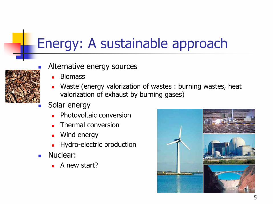
Energy: A sustainable approach
Alternative energy sources
Biomass
Waste (energy valorization of wastes : burning wastes, heat valorization of exhaust by burning gases)
Solar energy
Photovoltaic conversion
Thermal conversion
Wind energy
Hydro-electric production
Nuclear:
A new start?
5
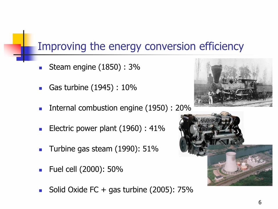
Improving the energy conversion efficiency
Steam engine (1850) : 3%
Gas turbine (1945) : 10%
Internal combustion engine (1950) : 20%
Electric power plant (1960) : 41%
Turbine gas steam (1990): 51%
Fuel cell (2000): 50%
Solid Oxide FC + gas turbine (2005): 75%
6
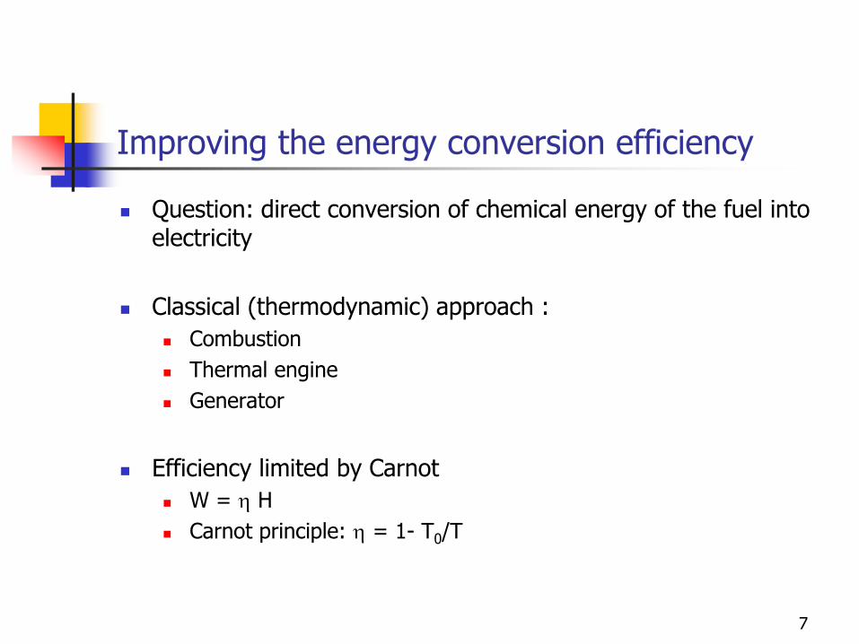
Improving the energy conversion efficiency
Question: direct conversion of chemical energy of the fuel into electricity
Classical (thermodynamic) approach :
Combustion
Thermal engine
Generator
Efficiency limited by Carnot
W = h H
Carnot principle: h = 1- T0/T
7

Direct conversion
Electrochemical systems
Volta batteries:
Closed system, irreversibility
Consumption of the reactants chemicals
Rechargeable batteries
Closed system but reversible
Regeneration of reactants
Fuel Cells
Open system
Reactant are continuously provided, while reaction products are eliminated
8
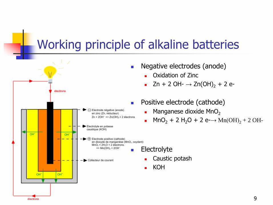
Working principle of alkaline batteries
Negative electrodes (anode)
Oxidation of Zinc
Zn + 2 OH- → Zn(OH)2 + 2 e-
Positive electrode (cathode)
Manganese dioxide MnO2
MnO2 + 2 H2O + 2 e-→ Mn(OH)2 + 2 OH-
Electrolyte
Caustic potash
KOH
9
What is a Fuel Cell?
Direct conversion of the chemical fuel into electricity using a electrochemistry process
Electrochemical reaction (oxidoreductase) without combustion (flame)
Reactants are continuously fed, converted and then eliminated
Reaction products are removed continuously
Protons / ions are carried out from one electrode to the other one through the electrolyte (liquid or solid)
Close to each electrode, there are highly conductive plates to collect and drain the current to external circuit.
Electrons exchanged during the reaction are conducted through the external electrical circuit.
10
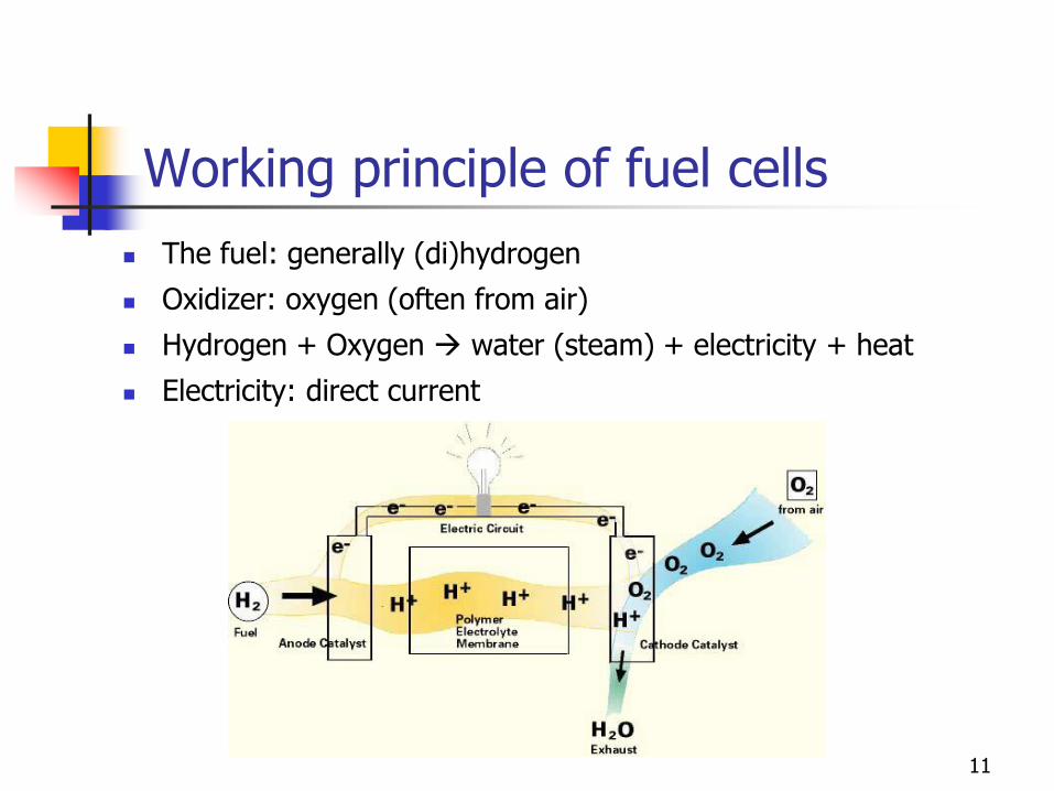
Working principle of fuel cells
The fuel: generally (di)hydrogen
Oxidizer: oxygen (often from air)
Hydrogen + Oxygen water (steam) + electricity + heat
Electricity: direct current
11

Working principle of H2 –O2 fuel cell
12
Working principle of H2 –O2 fuel cell
13
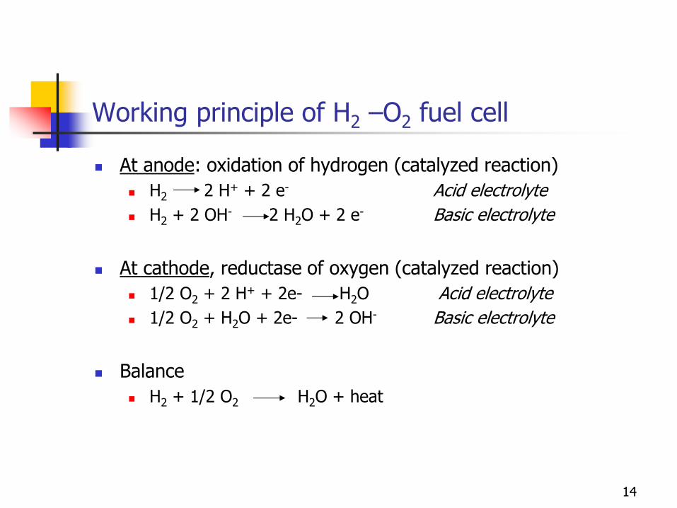
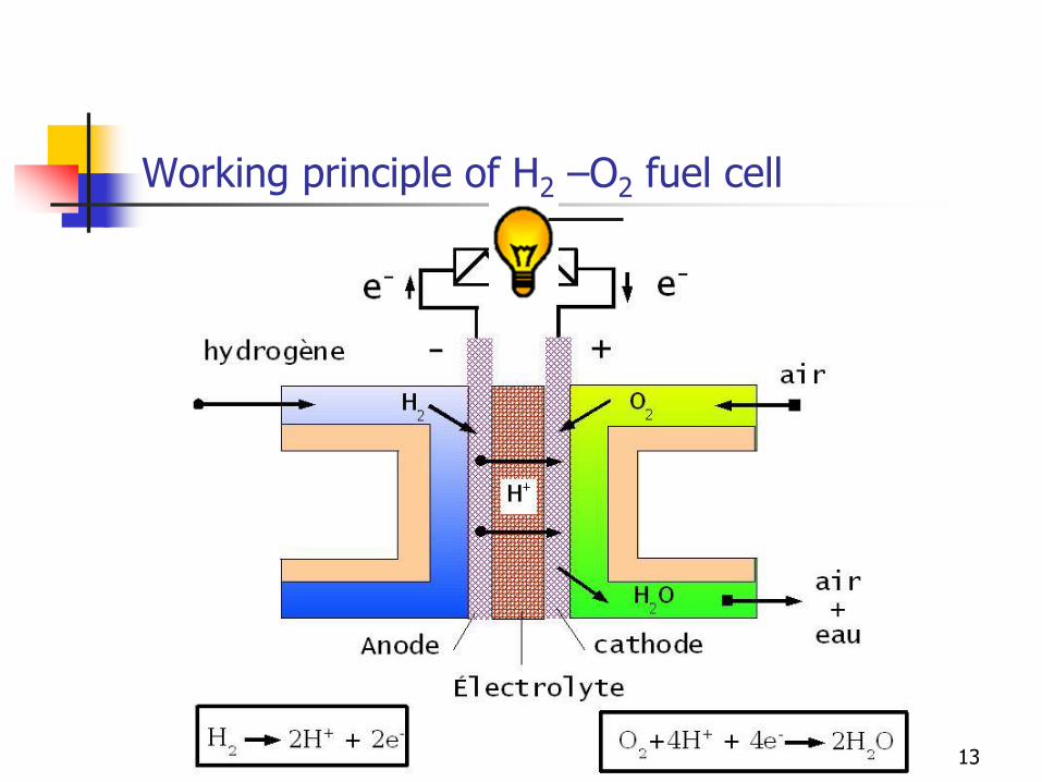
Working principle of H2 –O2 fuel cell
At anode: oxidation of hydrogen (catalyzed reaction)
H2 2 H+ + 2 e- Acid electrolyte
H2 + 2 OH- 2 H2O + 2 e- Basic electrolyte
At cathode, reductase of oxygen (catalyzed reaction)
1/2 O2 + 2 H+ + 2e- H2O Acid electrolyte
1/2 O2 + H2O + 2e- 2 OH- Basic electrolyte
Balance
H2 + 1/2 O2 H2O + heat
14
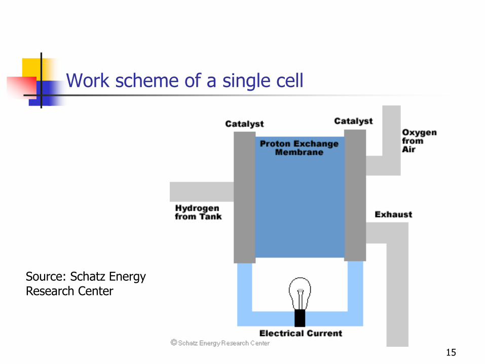
Work scheme of a single cell
Source: Schatz Energy Research Center
15
Working principle of H2 –O2 fuel cell
The fundamental working principle is the inverse reaction of water electrolysis
This chemical reaction is exothermic at 25 C.
Free enthalpy of the reaction is -237 or -229 kJ/mol depending on the fact if the produced water is under liquid or gaseous form.
This corresponds to theoretical voltages of 1,23 and 1,18 V. The voltage depends also of the temperature.
The reaction requires the presence of catalyst (Pt or Pt/Ru) to activate (accelerate) the reaction speed.
16
Working principle of H2 –O2 fuel cell
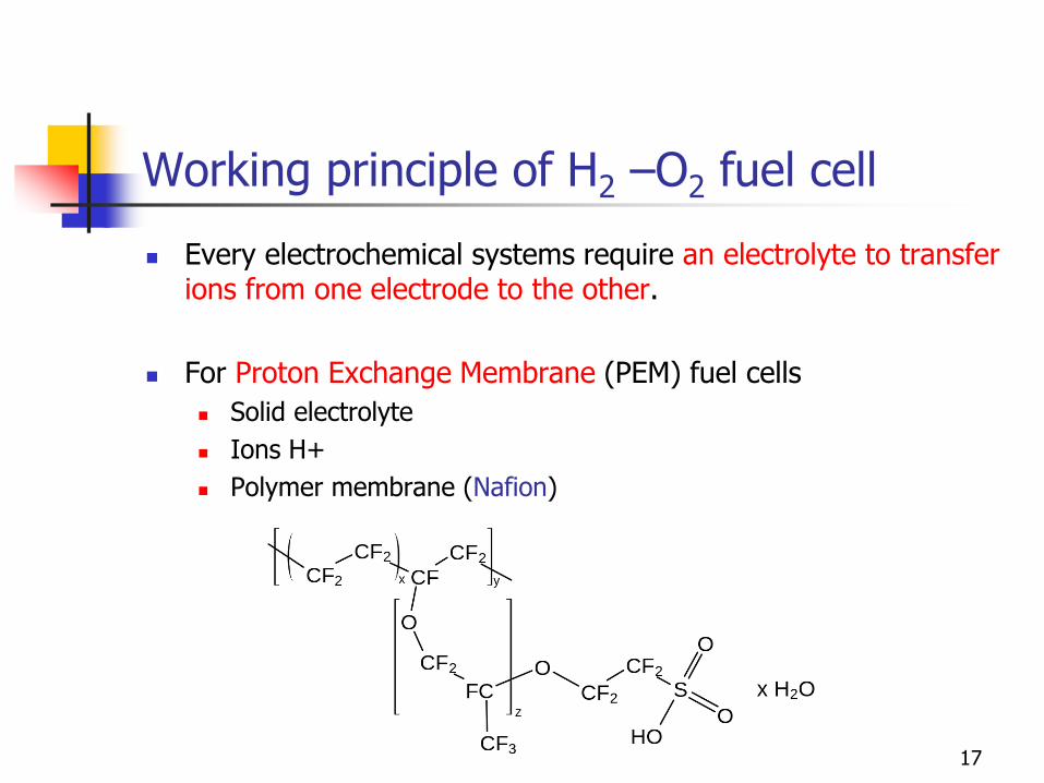
Every electrochemical systems require an electrolyte to transfer ions from one electrode to the other.
For Proton Exchange Membrane (PEM) fuel cells
Solid electrolyte
Ions H+
Polymer membrane (Nafion)
17
Working principle of H2 –O2 fuel cell
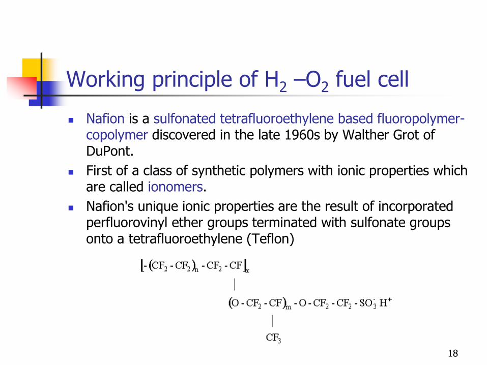
Nafion is a sulfonated tetrafluoroethylene based fluoropolymer-copolymer discovered in the late 1960s by Walther Grot of DuPont.
First of a class of synthetic polymers with ionic properties which are called ionomers.
Nafion's unique ionic properties are the result of incorporated perfluorovinyl ether groups terminated with sulfonate groups onto a tetrafluoroethylene (Teflon)
18
Working principle of H2 –O2 fuel cell
Advantages:
Operating generally at low or moderate temperatures
Silent operation
High theoretical efficiency
Drawbacks:
Cost of electrodes
Purity of fuel
Limited power density
19
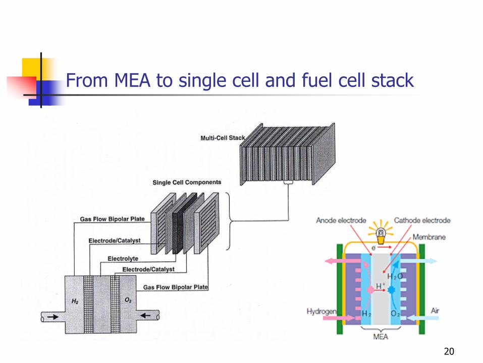
From MEA to single cell and fuel cell stack
20
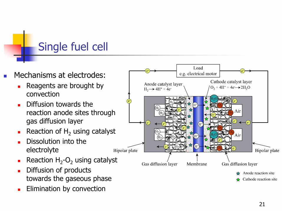
Single fuel cell
21
Mechanisms at electrodes:
Reagents are brought by convection
Diffusion towards the reaction anode sites through gas diffusion layer
Reaction of H2 using catalyst
Dissolution into the electrolyte
Reaction H2-O2 using catalyst
Diffusion of products towards the gaseous phase
Elimination by convection
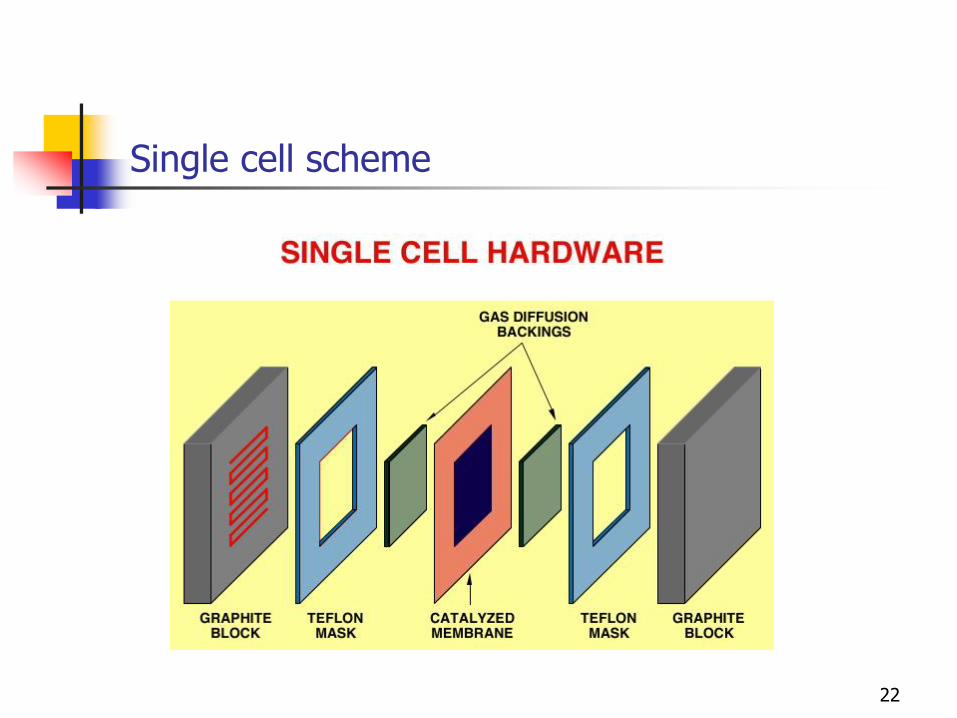
Single cell scheme
22
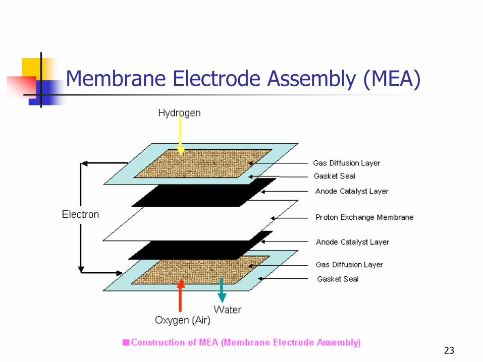
Membrane Electrode Assembly (MEA)
23
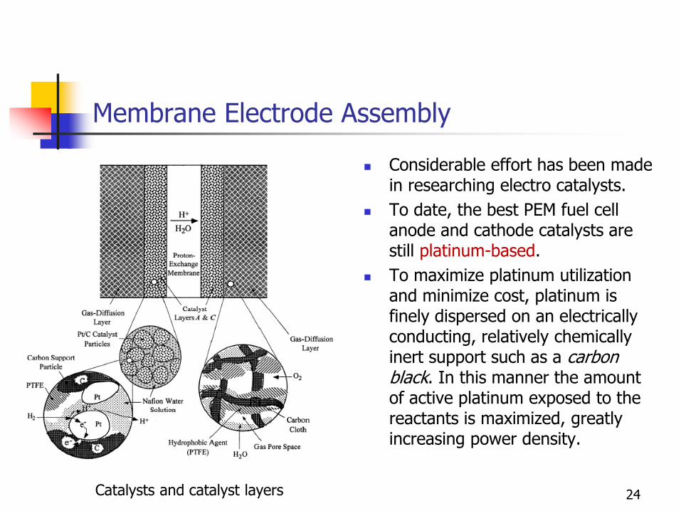
Membrane Electrode Assembly
Considerable effort has been made in researching electro catalysts.
To date, the best PEM fuel cell anode and cathode catalysts are still platinum-based.
To maximize platinum utilization and minimize cost, platinum is finely dispersed on an electrically conducting, relatively chemically inert support such as a carbon black. In this manner the amount of active platinum exposed to the reactants is maximized, greatly increasing power density.
24 Catalysts and catalyst layers
Membrane Electrode Assembly
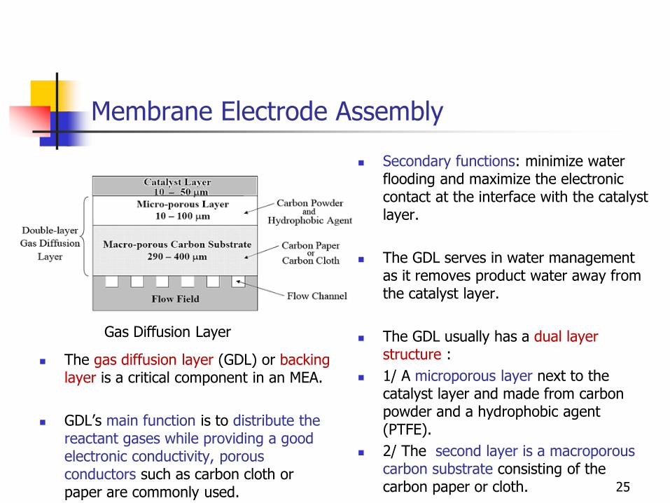
Secondary functions: minimize water flooding and maximize the electronic contact at the interface with the catalyst layer.
The GDL serves in water management as it removes product water away from the catalyst layer.
The GDL usually has a dual layer structure :
1/ A microporous layer next to the catalyst layer and made from carbon powder and a hydrophobic agent (PTFE).
2/ The second layer is a macroporous carbon substrate consisting of the carbon paper or cloth. 25
Gas Diffusion Layer
The gas diffusion layer (GDL) or backing layer is a critical component in an MEA.
GDL’s main function is to distribute the reactant gases while providing a good electronic conductivity, porous conductors such as carbon cloth or paper are commonly used.
Membrane Electrode Assembly (MEA)
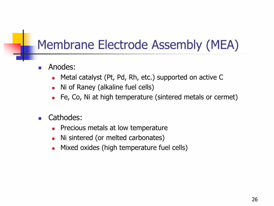
Anodes:
Metal catalyst (Pt, Pd, Rh, etc.) supported on active C
Ni of Raney (alkaline fuel cells)
Fe, Co, Ni at high temperature (sintered metals or cermet)
Cathodes:
Precious metals at low temperature
Ni sintered (or melted carbonates)
Mixed oxides (high temperature fuel cells)
26
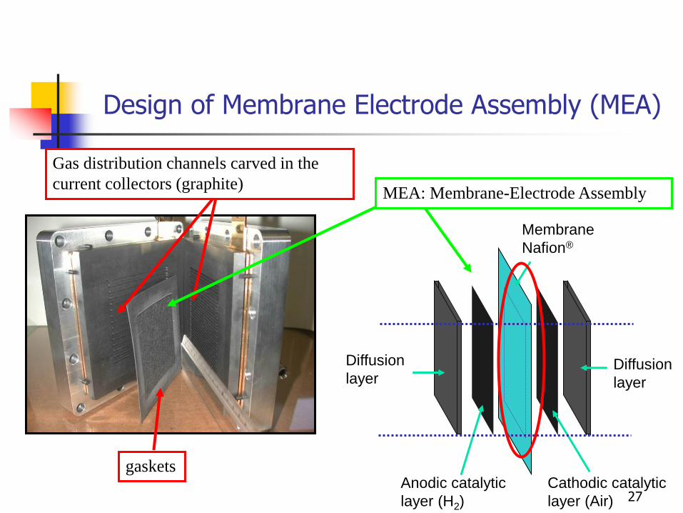
Gas distribution channels carved in the
current collectors (graphite)
gaskets Cathodic catalytic
layer (Air)
Diffusion
layer
MEA: Membrane-Electrode Assembly
Membrane
Nafion®
Anodic catalytic
layer (H2)
Diffusion
layer
27
Design of Membrane Electrode Assembly (MEA)

20 - 30 µm
me
mb
rane
Diffu
sio
n laye
r
Catalytic
layer
e-
H+
O2
H2O
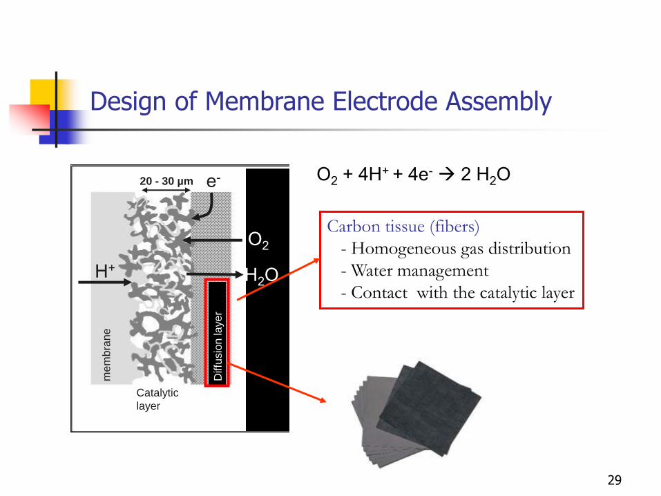
O2 + 4H+ + 4e- 2 H2O
Proton conducting polymer (Nafion)
- Hydration
- Damaging due to heat (> 120°C)
- Mechanical damaging
- Contact membrane/catalytic layer
- Cost
Nafion
Design of Membrane Electrode Assembly
28
20 - 30 µm
me
mb
rane
Diffu
sio
n laye
r
Catalytic
layer
e-
H+
O2
H2O
O2 + 4H+ + 4e- 2 H2O
Carbon tissue (fibers)
- Homogeneous gas distribution
- Water management
- Contact with the catalytic layer
Design of Membrane Electrode Assembly
29
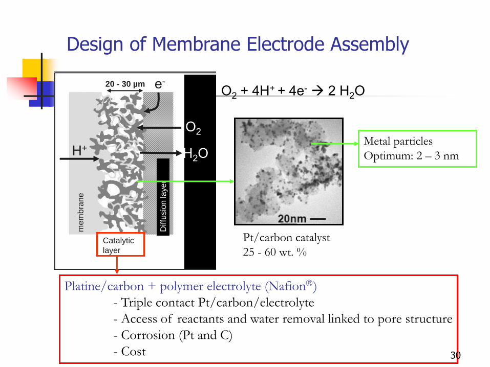
20 - 30 µm m
em
bra
ne
Diffu
sio
n la
ye
r
Catalytic
layer
e-
H+
O2
H2O
O2 + 4H+ + 4e- 2 H2O
Pt/carbon catalyst
25 - 60 wt. %
Metal particles
Optimum: 2 – 3 nm
Platine/carbon + polymer electrolyte (Nafion)
- Triple contact Pt/carbon/electrolyte
- Access of reactants and water removal linked to pore structure
- Corrosion (Pt and C)
- Cost
Design of Membrane Electrode Assembly
30
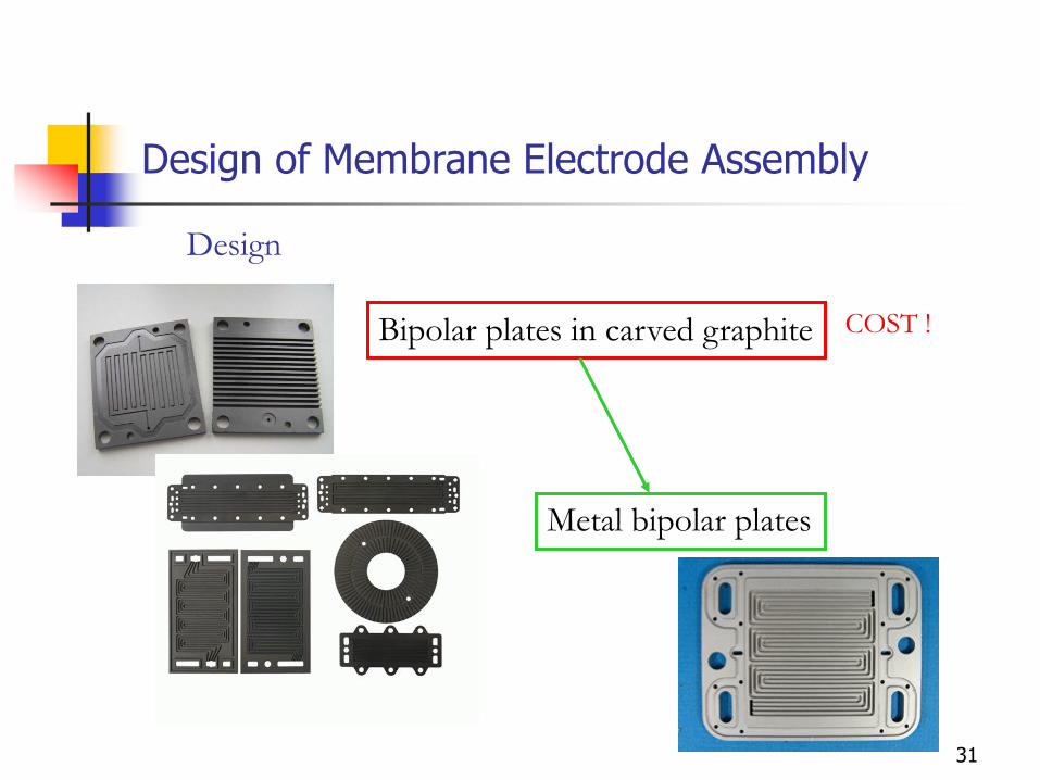
Bipolar plates in carved graphite
Metal bipolar plates
Design
COST !
Design of Membrane Electrode Assembly
31
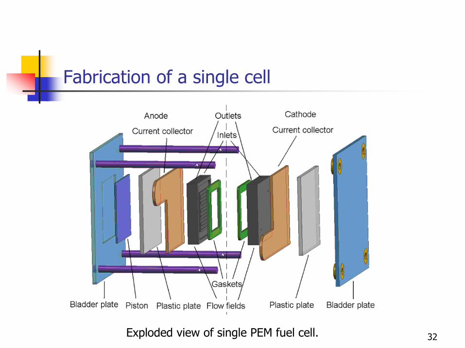
Fabrication of a single cell
32 Exploded view of single PEM fuel cell.

Fabrication of a single cell
33
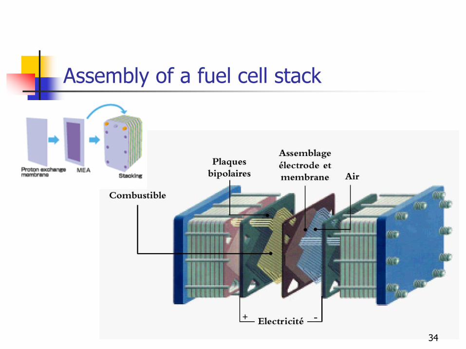
Assembly of a fuel cell stack
34
Assembly of a fuel cell stack
35
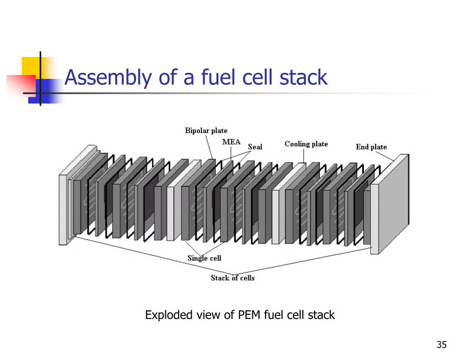
Exploded view of PEM fuel cell stack
Assembly of a fuel cell stack
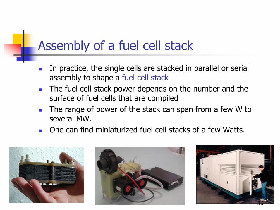
In practice, the single cells are stacked in parallel or serial assembly to shape a fuel cell stack
The fuel cell stack power depends on the number and the surface of fuel cells that are compiled
The range of power of the stack can span from a few W to several MW.
One can find miniaturized fuel cell stacks of a few Watts.
36
Fuel cell systems
37
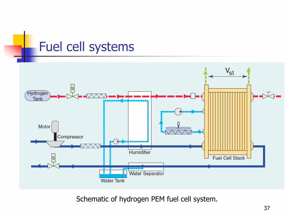
Schematic of hydrogen PEM fuel cell system.
Fuel cell systems
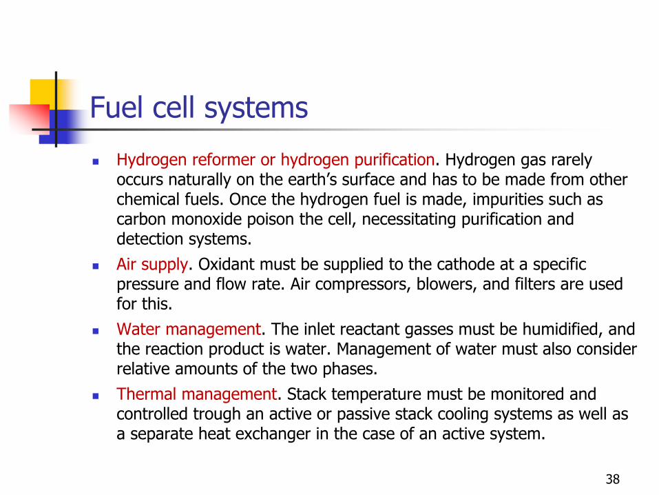
Hydrogen reformer or hydrogen purification. Hydrogen gas rarely occurs naturally on the earth’s surface and has to be made from other chemical fuels. Once the hydrogen fuel is made, impurities such as carbon monoxide poison the cell, necessitating purification and detection systems.
Air supply. Oxidant must be supplied to the cathode at a specific pressure and flow rate. Air compressors, blowers, and filters are used for this.
Water management. The inlet reactant gasses must be humidified, and the reaction product is water. Management of water must also consider relative amounts of the two phases.
Thermal management. Stack temperature must be monitored and controlled trough an active or passive stack cooling systems as well as a separate heat exchanger in the case of an active system.
38
Conversion efficiency of a Fuel Cell
39
Characteristics of an elementary fuel cell
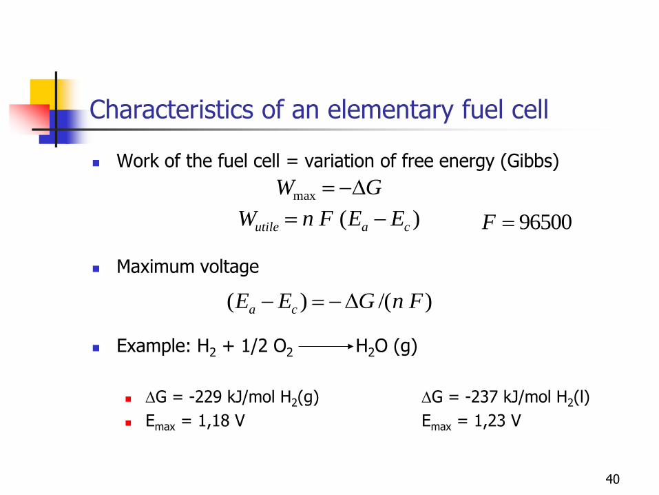
Work of the fuel cell = variation of free energy (Gibbs)
Maximum voltage
Example: H2 + 1/2 O2 H2O (g)
DG = -229 kJ/mol H2(g) DG = -237 kJ/mol H2(l)
Emax = 1,18 V Emax = 1,23 V
GW Dmax
)( cautile EEFnW 96500F
)/()( FnGEE ca D
40
Characteristics of an elementary fuel cell
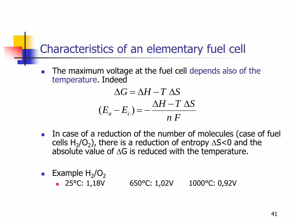
The maximum voltage at the fuel cell depends also of the temperature. Indeed
In case of a reduction of the number of molecules (case of fuel cells H2/O2), there is a reduction of entropy DS<0 and the absolute value of DG is reduced with the temperature.
Example H2/O2
25°C: 1,18V 650°C: 1,02V 1000°C: 0,92V
STHG DDD
Fn
STHEE ca
DD )(
41
Characteristics of an elementary fuel cell
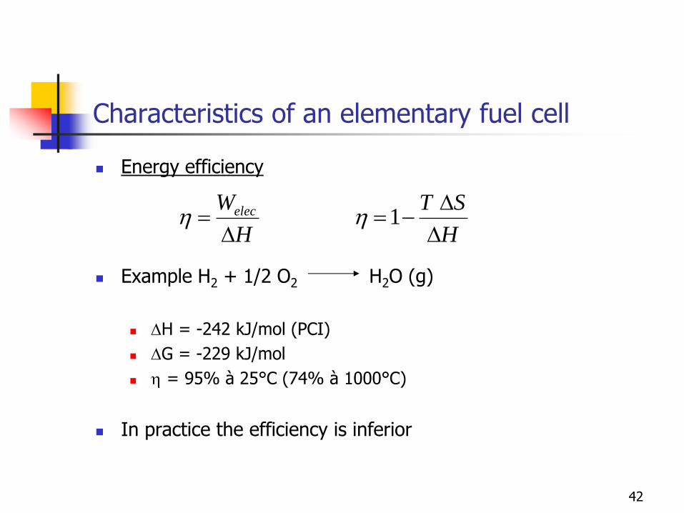
Energy efficiency
Example H2 + 1/2 O2 H2O (g)
DH = -242 kJ/mol (PCI)
DG = -229 kJ/mol
h = 95% à 25°C (74% à 1000°C)
In practice the efficiency is inferior
H
Welec
Dh
H
ST
D
D1h
42
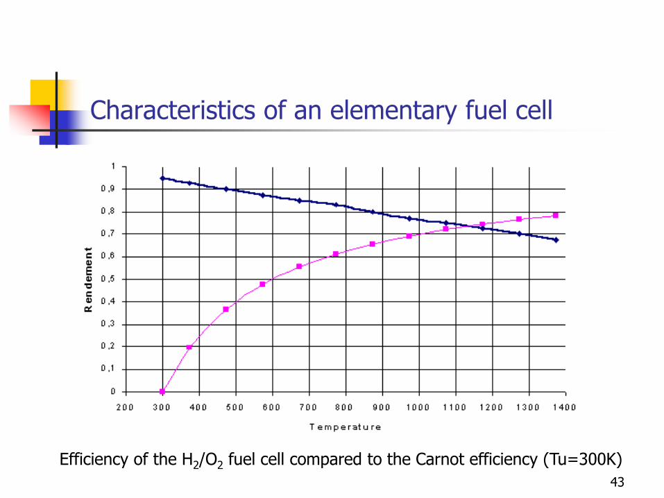
Characteristics of an elementary fuel cell
Efficiency of the H2/O2 fuel cell compared to the Carnot efficiency (Tu=300K)
43
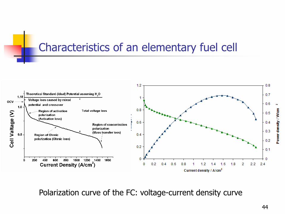
Characteristics of an elementary fuel cell
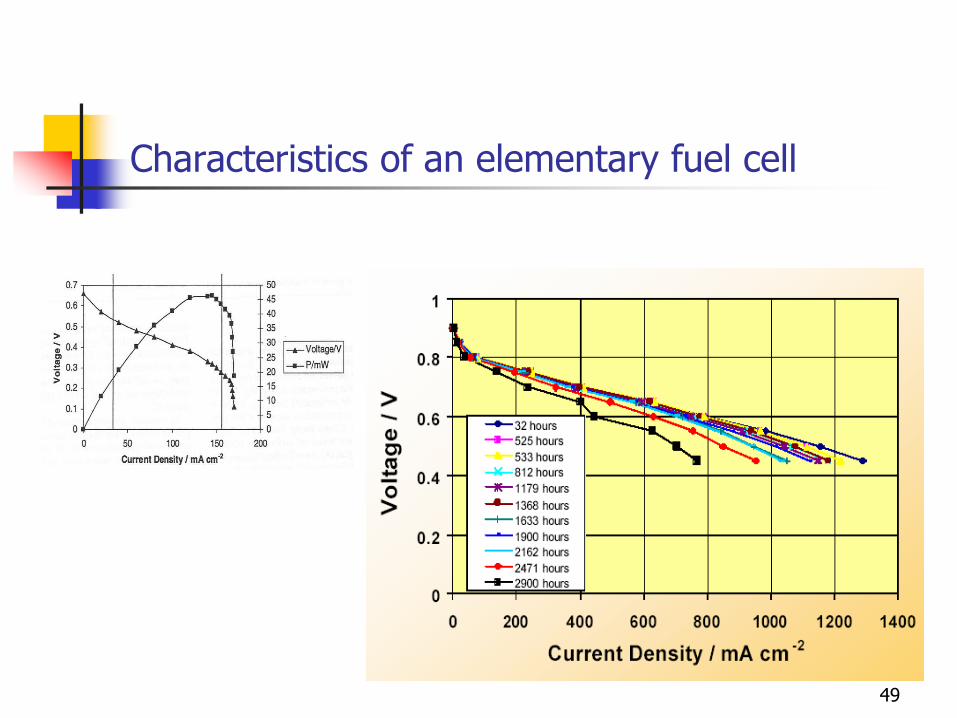
Polarization curve of the FC: voltage-current density curve
44
Characteristics of an elementary fuel cell
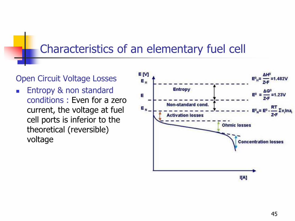
Open Circuit Voltage Losses
Entropy & non standard conditions : Even for a zero current, the voltage at fuel cell ports is inferior to the theoretical (reversible) voltage
45
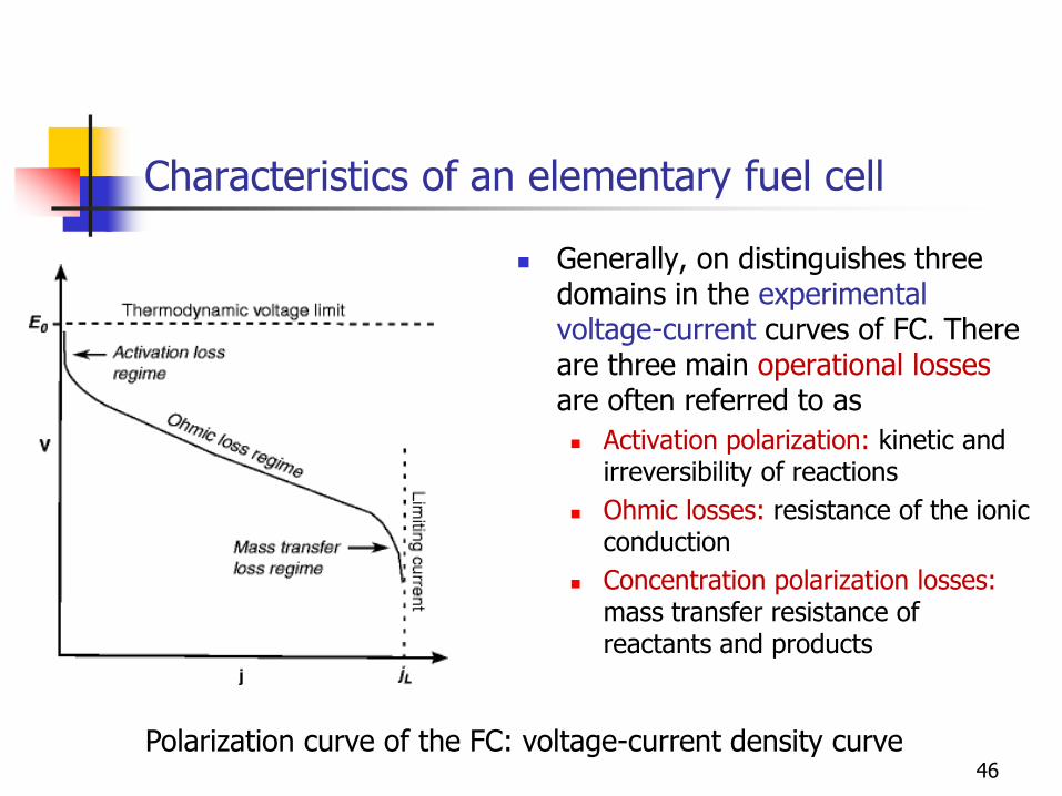
Characteristics of an elementary fuel cell
Generally, on distinguishes three domains in the experimental voltage-current curves of FC. There are three main operational losses are often referred to as
Activation polarization: kinetic and irreversibility of reactions
Ohmic losses: resistance of the ionic conduction
Concentration polarization losses: mass transfer resistance of reactants and products
46
Polarization curve of the FC: voltage-current density curve
Characteristics of an elementary fuel cell
1/ Activation loss regime: Even for zero and very low currents, there are irreversible losses. These stem from the activation energy of the electrochemical reactions at the electrodes [mainly at cathode electrode (oxygen)].
These losses depend on the reactions at hand, the electro-catalyst material and microstructure, reactant activities (and hence utilization), and weakly on current density. They are related to the finite speed (kinetic) of electrochemical reactions.
The activation losses related to charge transfer are ruled by the Butler Vollmer law.
47
Characteristics of an elementary fuel cell
2/ Ohmic loss regime: For intermediate current density, where the FC is generally used, the losses increase linearly with the current density. It is typical from ohmic losses due to internal resistance of the ion current across the electrolyte and the membrane, and the electronic resistance in the electrodes, current collectors and interconnects, and contact resistances.
Ohmic losses are proportional to the current density, depend on materials selection and stack geometry, and on temperature.
3/ Mass transfer loss regime: For high current densities, the losses increase drastically. The over tensions result from the finite mass transport limitations rates of the reactants and the products of the reaction to and from the electrodes. These losses depend strongly on the current density, reactant activity, and electrode structure. It is therefore also denominated as the concentration polarization.
48
Characteristics of an elementary fuel cell
49
Loss of efficiency
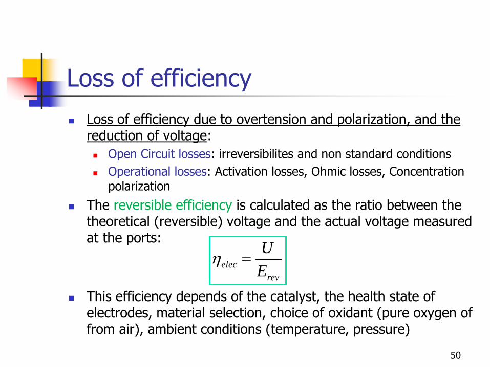
Loss of efficiency due to overtension and polarization, and the reduction of voltage:
Open Circuit losses: irreversibilites and non standard conditions
Operational losses: Activation losses, Ohmic losses, Concentration polarization
The reversible efficiency is calculated as the ratio between the theoretical (reversible) voltage and the actual voltage measured at the ports:
This efficiency depends of the catalyst, the health state of electrodes, material selection, choice of oxidant (pure oxygen of from air), ambient conditions (temperature, pressure)
rev
elecE
Uh
50
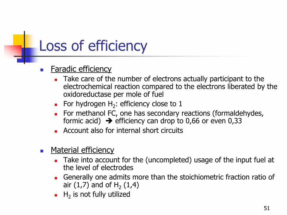
Loss of efficiency
Faradic efficiency Take care of the number of electrons actually participant to the
electrochemical reaction compared to the electrons liberated by the oxidoreductase per mole of fuel
For hydrogen H2: efficiency close to 1
For methanol FC, one has secondary reactions (formaldehydes, formic acid) efficiency can drop to 0,66 or even 0,33
Account also for internal short circuits
Material efficiency Take into account for the (uncompleted) usage of the input fuel at
the level of electrodes
Generally one admits more than the stoichiometric fraction ratio of air (1,7) and of H2 (1,4)
H2 is not fully utilized
51
Loss of efficiency
System efficiency
In mobile and stationary applications, the fuel cell does not work isolated.
Several auxiliaries are necessary: air compressors, control systems, thermal control, reforming and purification of H2 (desulfuration, Hydrogen purification, heat exchangers)
Generally they have a global efficiency of 80%
52
Global efficiency of the FC system
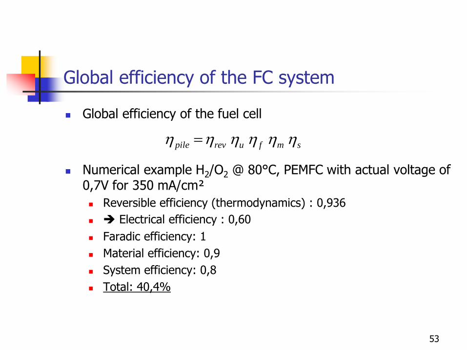
Global efficiency of the fuel cell
Numerical example H2/O2 @ 80°C, PEMFC with actual voltage of 0,7V for 350 mA/cm²
Reversible efficiency (thermodynamics) : 0,936
Electrical efficiency : 0,60
Faradic efficiency: 1
Material efficiency: 0,9
System efficiency: 0,8
Total: 40,4%
smfurevpile hhhhhh
53

Fuel cell technologies
54
Fuel cell technologies
One distinguishes 6 types of fuel cells:
AFC: Alkaline Fuel Cell
PEMFC: Polymer Exchange Membrane Fuel Cell
DMFC: Direct Methanol Fuel Cell
PAFC : Phosphoric Acid Fuel Cell
MCFC: Molten Carbonate Fuel Cell
SOFC: Solid Oxide Fuel Cell
55

Fuel cell technologies
The different cell technologies are characterized by:
The type of fuel: hydrogen, methanol, natural gas
The nature of the electrolyte
The kind of the transported ions: H+, OH- or carbonate
The operating temperature
The architecture of the fuel
The size of the application (buildings, vehicle, electricity power plant, computer, portable communication equipment and by the nature of the application (mobile or stationary)
56
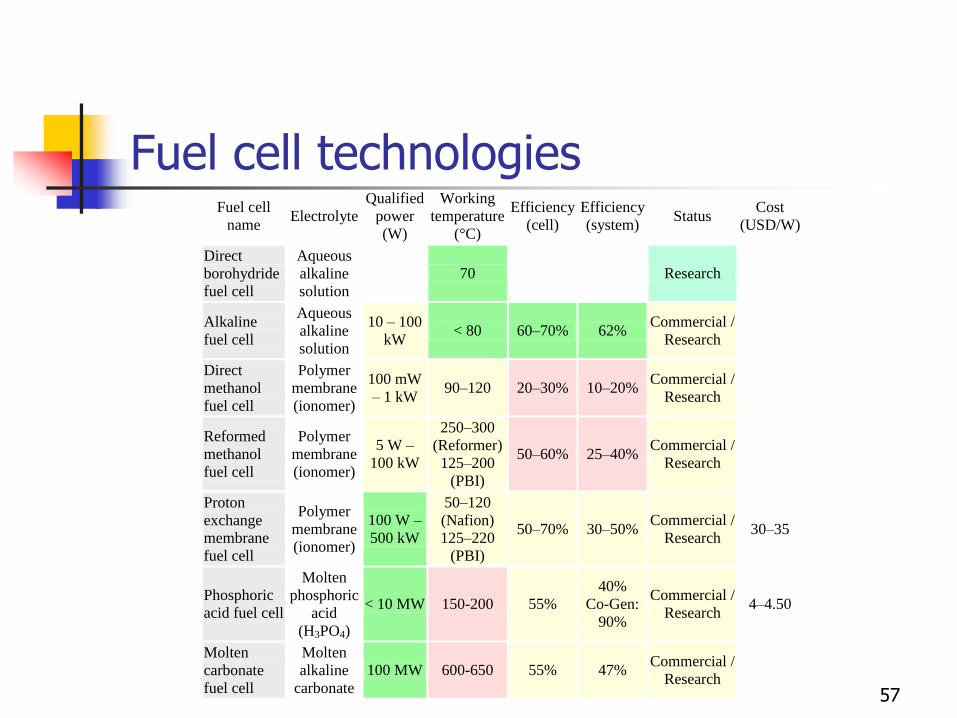
Fuel cell technologies Fuel cell
name Electrolyte
Qualified
power
(W)
Working
temperature
(°C)
Efficiency
(cell)
Efficiency
(system) Status
Cost
(USD/W)
Direct
borohydride
fuel cell
Aqueous
alkaline
solution
70
Research
Alkaline
fuel cell
Aqueous
alkaline
solution
10 – 100
kW < 80 60–70% 62%
Commercial /
Research
Direct
methanol
fuel cell
Polymer
membrane
(ionomer)
100 mW
– 1 kW 90–120 20–30% 10–20%
Commercial /
Research
Reformed
methanol
fuel cell
Polymer
membrane
(ionomer)
5 W –
100 kW
250–300
(Reformer)
125–200
(PBI)
50–60% 25–40% Commercial /
Research
Proton
exchange
membrane
fuel cell
Polymer
membrane
(ionomer)
100 W –
500 kW
50–120
(Nafion)
125–220
(PBI)
50–70% 30–50% Commercial /
Research 30–35
Phosphoric
acid fuel cell
Molten
phosphoric
acid
(H3PO4)
< 10 MW 150-200 55%
40%
Co-Gen:
90%
Commercial /
Research 4–4.50
Molten
carbonate
fuel cell
Molten
alkaline
carbonate
100 MW 600-650 55% 47% Commercial /
Research
57
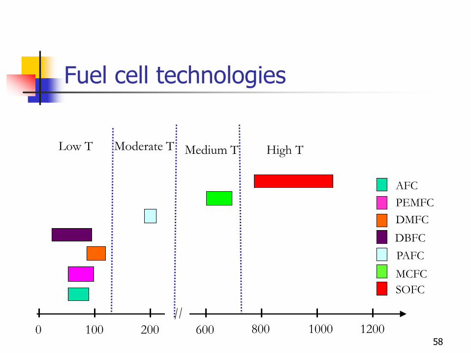
Low T Moderate T Medium T High T
100 200 600 800 1000 1200 0
AFC
PEMFC
DMFC
PAFC
MCFC
SOFC
DBFC
Fuel cell technologies
58
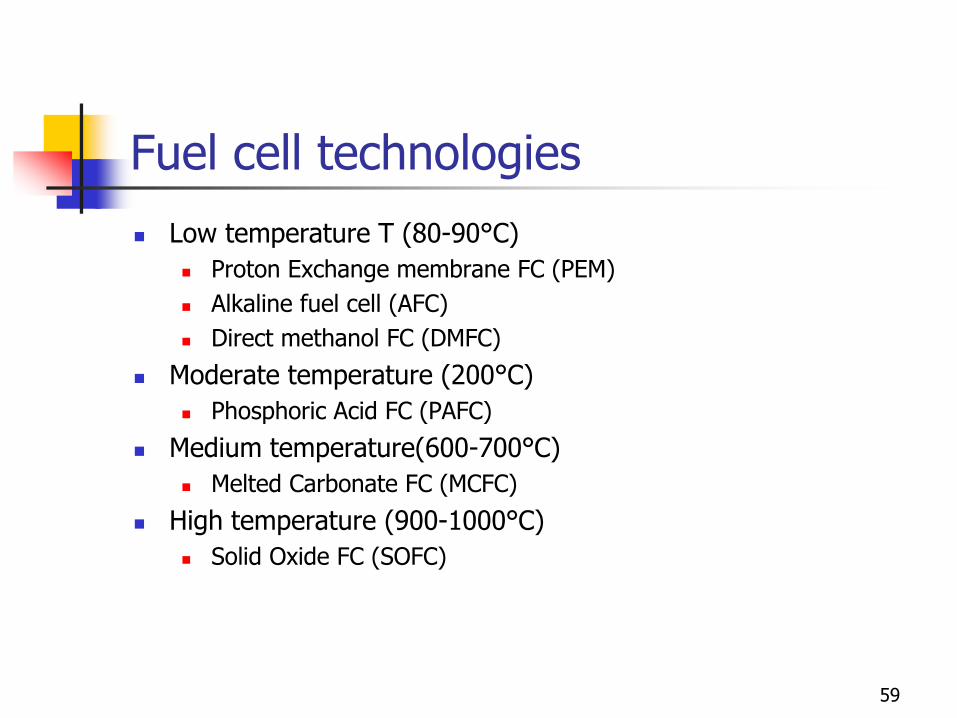
Fuel cell technologies
Low temperature T (80-90°C)
Proton Exchange membrane FC (PEM)
Alkaline fuel cell (AFC)
Direct methanol FC (DMFC)
Moderate temperature (200°C)
Phosphoric Acid FC (PAFC)
Medium temperature(600-700°C)
Melted Carbonate FC (MCFC)
High temperature (900-1000°C)
Solid Oxide FC (SOFC)
59
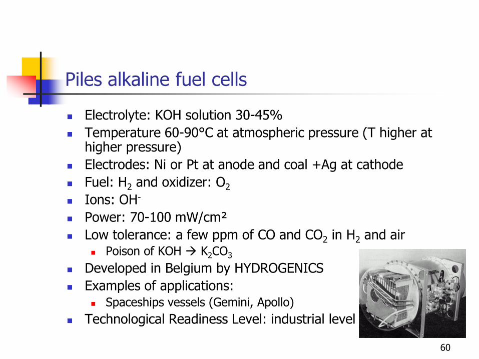
Piles alkaline fuel cells
Electrolyte: KOH solution 30-45%
Temperature 60-90°C at atmospheric pressure (T higher at higher pressure)
Electrodes: Ni or Pt at anode and coal +Ag at cathode
Fuel: H2 and oxidizer: O2
Ions: OH-
Power: 70-100 mW/cm²
Low tolerance: a few ppm of CO and CO2 in H2 and air Poison of KOH K2CO3
Developed in Belgium by HYDROGENICS
Examples of applications: Spaceships vessels (Gemini, Apollo)
Technological Readiness Level: industrial level
60
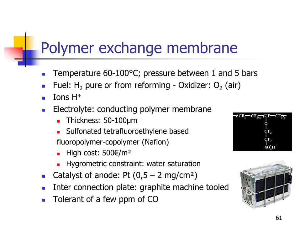
Polymer exchange membrane
Temperature 60-100°C; pressure between 1 and 5 bars
Fuel: H2 pure or from reforming - Oxidizer: O2 (air)
Ions H+
Electrolyte: conducting polymer membrane
Thickness: 50-100µm
Sulfonated tetrafluoroethylene based
fluoropolymer-copolymer (Nafion)
High cost: 500€/m²
Hygrometric constraint: water saturation
Catalyst of anode: Pt (0,5 – 2 mg/cm²)
Inter connection plate: graphite machine tooled
Tolerant of a few ppm of CO
61
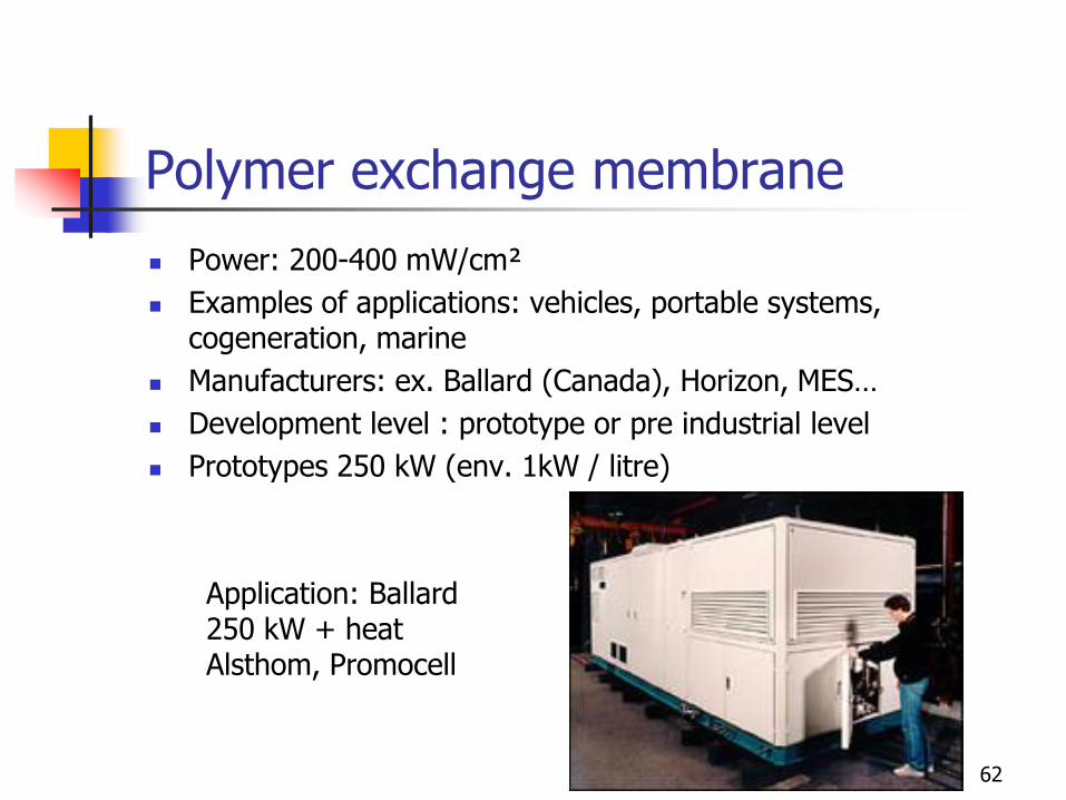
Polymer exchange membrane
Power: 200-400 mW/cm²
Examples of applications: vehicles, portable systems, cogeneration, marine
Manufacturers: ex. Ballard (Canada), Horizon, MES…
Development level : prototype or pre industrial level
Prototypes 250 kW (env. 1kW / litre)
Application: Ballard 250 kW + heat Alsthom, Promocell
62
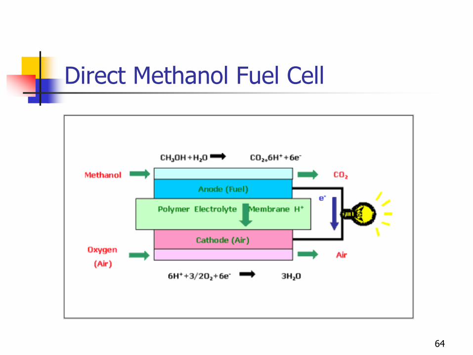
Direct Methanol Fuel Cell
Anode: methanol supply (CH3OH)
CH3OH + H2O CO2 + 6 H+ + 6e-
Cathode: oxygen oxidizer (O2 )
Temperature 60-100°C; pressure between 1 and 5 bars
Fuel: methanol - Oxidizer: O2 (air)
Ions H+
Electrolyte: polymer exchange membrane
63
Direct Methanol Fuel Cell
64

Direct Methanol Fuel Cell
65
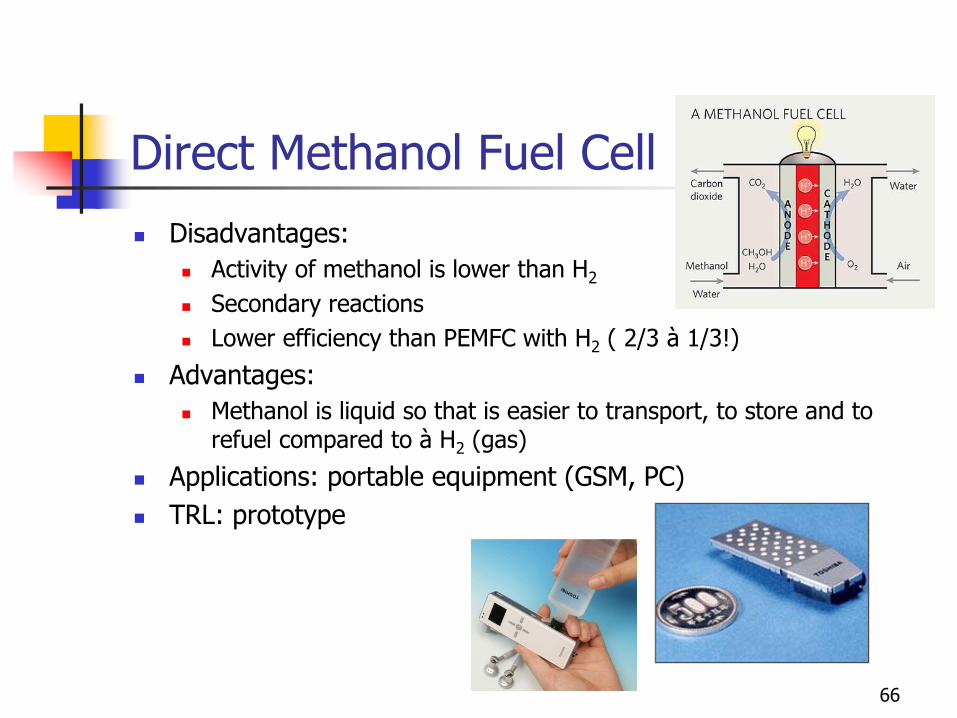
Direct Methanol Fuel Cell
Disadvantages:
Activity of methanol is lower than H2
Secondary reactions
Lower efficiency than PEMFC with H2 ( 2/3 à 1/3!)
Advantages:
Methanol is liquid so that is easier to transport, to store and to refuel compared to à H2 (gas)
Applications: portable equipment (GSM, PC)
TRL: prototype
66
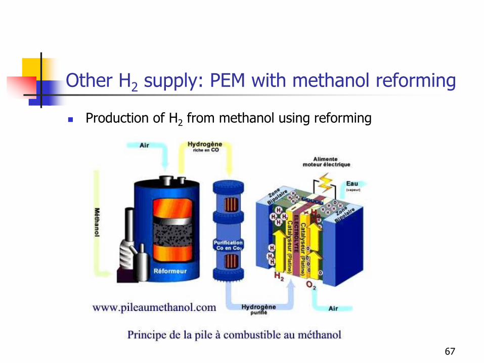
Other H2 supply: PEM with methanol reforming
Production of H2 from methanol using reforming
67
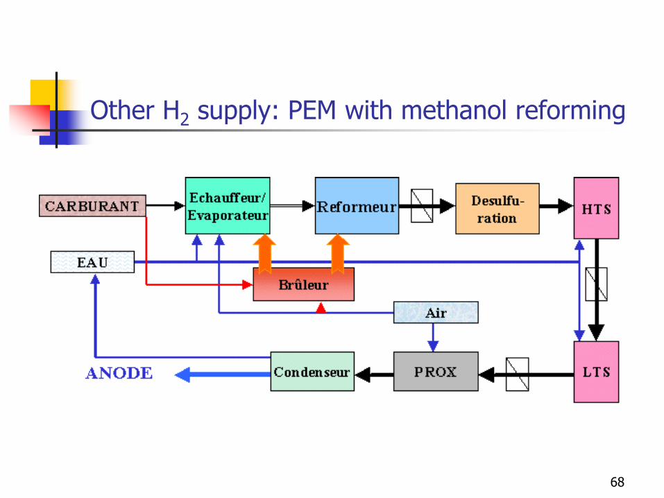
Other H2 supply: PEM with methanol reforming
68
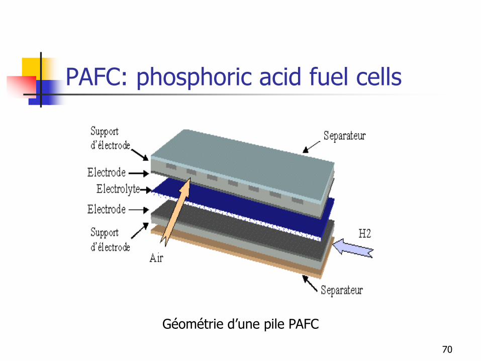
PAFC: phosphoric acid fuel cells
Electrolyte: phosphoric acid H3PO4 100%
Temperature 180-220°C
Fuel: H2 pure or from reforming - Oxidizer: O2 (air)
Ions H+
Power density: 100 – 300 mW/cm²
Tolerance: 1% CO
Applications: cogeneration
TRL: mature technology
69
PAFC: phosphoric acid fuel cells
Géométrie d’une pile PAFC
70

PAFC: phosphoric acid fuel cells
A fuel cell O.N.S.I. of 200 kWe and 200 kWth was installed in
France in Celles by E.D.F. and G.D.F., for a demonstration project. It
consumes natural gas provided by G.D.F and provides electrical
energy as well as heat up to 80°C 71
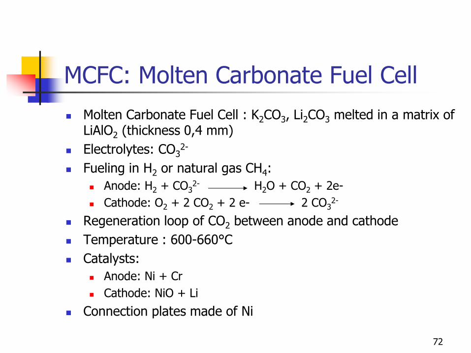
MCFC: Molten Carbonate Fuel Cell
Molten Carbonate Fuel Cell : K2CO3, Li2CO3 melted in a matrix of LiAlO2 (thickness 0,4 mm)
Electrolytes: CO32-
Fueling in H2 or natural gas CH4:
Anode: H2 + CO32- H2O + CO2 + 2e-
Cathode: O2 + 2 CO2 + 2 e- 2 CO32-
Regeneration loop of CO2 between anode and cathode
Temperature : 600-660°C
Catalysts:
Anode: Ni + Cr
Cathode: NiO + Li
Connection plates made of Ni
72
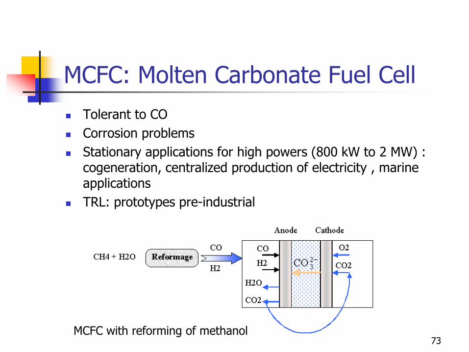
MCFC: Molten Carbonate Fuel Cell
Tolerant to CO
Corrosion problems
Stationary applications for high powers (800 kW to 2 MW) : cogeneration, centralized production of electricity , marine applications
TRL: prototypes pre-industrial
MCFC with reforming of methanol 73
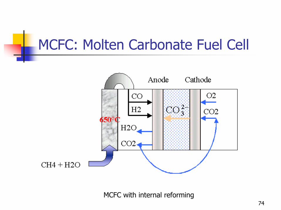
MCFC: Molten Carbonate Fuel Cell
MCFC with internal reforming 74

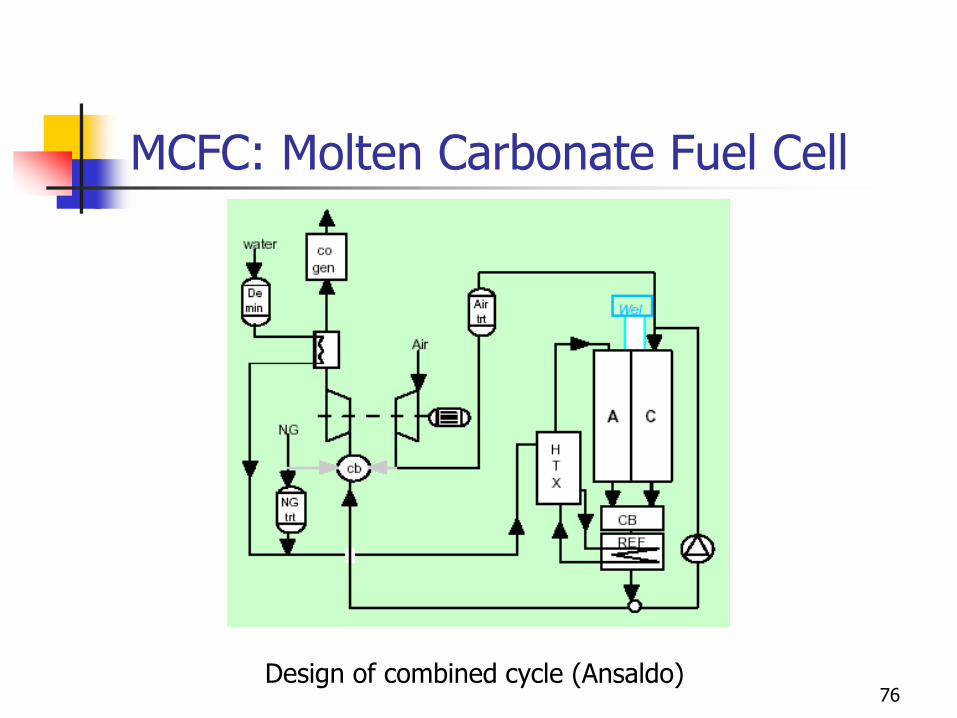
MCFC: Molten Carbonate Fuel Cell
Several advantages of MCFC
High electrical efficiency (60%),
Utilization of produced heat for cogeneration or internal reforming and combination with gas turbine,
Possible to use fuels as methane, methanol, ethanol or gasified coal...
Possible to use non precious metal as catalyst metals in electrodes.
75
MCFC: Molten Carbonate Fuel Cell
Design of combined cycle (Ansaldo) 76
MCFC: Molten Carbonate Fuel Cell
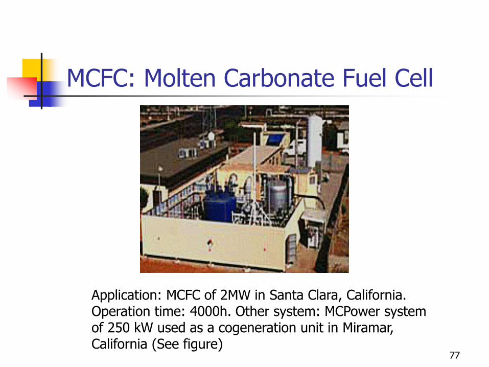
Application: MCFC of 2MW in Santa Clara, California. Operation time: 4000h. Other system: MCPower system of 250 kW used as a cogeneration unit in Miramar, California (See figure)
77
Solid Oxide Fuel Cell : SOFC
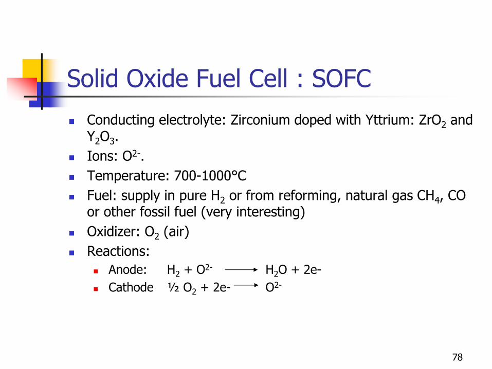
Conducting electrolyte: Zirconium doped with Yttrium: ZrO2 and Y2O3.
Ions: O2-.
Temperature: 700-1000°C
Fuel: supply in pure H2 or from reforming, natural gas CH4, CO or other fossil fuel (very interesting)
Oxidizer: O2 (air)
Reactions:
Anode: H2 + O2- H2O + 2e-
Cathode ½ O2 + 2e- O2-
78
Solid Oxide Fuel Cell : SOFC
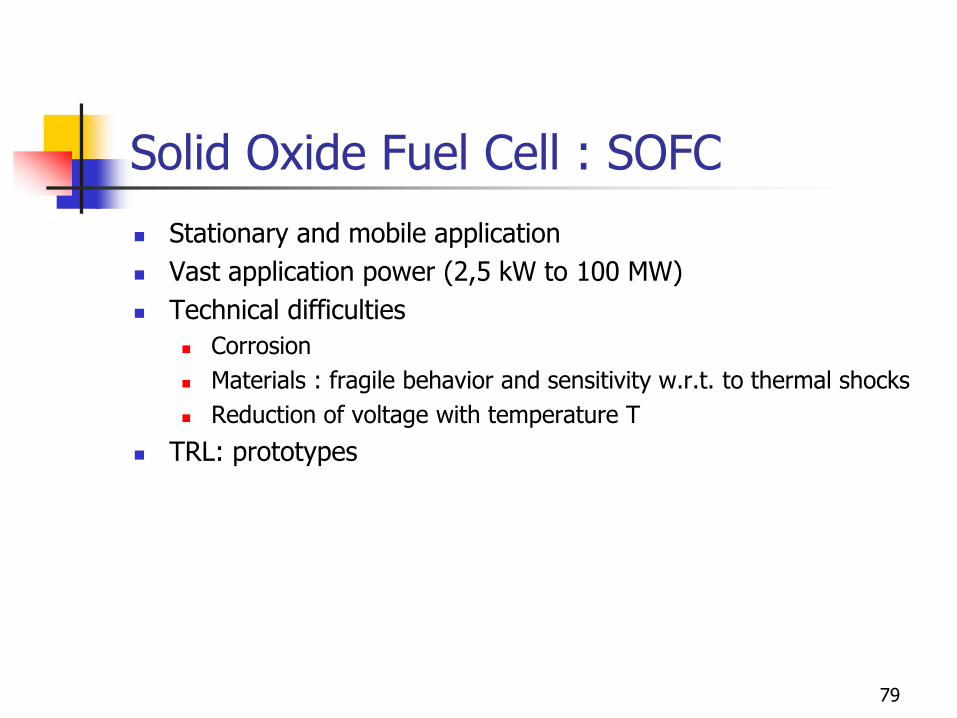
Stationary and mobile application
Vast application power (2,5 kW to 100 MW)
Technical difficulties
Corrosion
Materials : fragile behavior and sensitivity w.r.t. to thermal shocks
Reduction of voltage with temperature T
TRL: prototypes
79
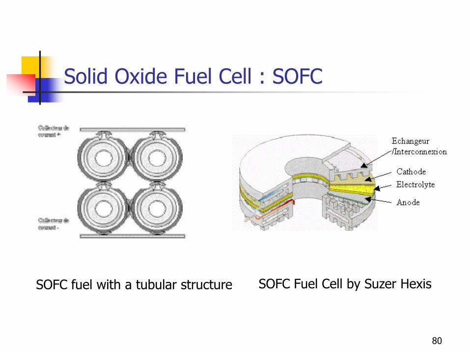
Solid Oxide Fuel Cell : SOFC
SOFC Fuel Cell by Suzer Hexis SOFC fuel with a tubular structure
80
Hydrogen as a fuel
81
Fuel treatment
H2: difficulty of storage and distribution network
CH3OH: reforming process is a classical technology but remains costly
Natural gas (CH4):
Desulfuration
Reforming
Elimination of CO2 and of CO (except MCFC)
Utilization of un reacted H2
Compression: energy loss
Opportunity for partial oxidation based systems
82
Hydrogen production paths
Water electrolysis
Environmental impact depends on the CO2 emission of electrical network
Low overall efficiency (<60%)
Advantages: enables a massive energy storage of electricity and allows to
level the production peeks
Reforming of fossil fuel from natural gas or oil
Production of CO2 and dependency to oil
Emissions in upstream level
Is considered as the best option currently
Hydrogen « lost » in industrial processe (chemical industry in processes)
Poly generation
Production of heat, energy and fuel in large scale energy systems. Possibility to perform Carbone capture sequestration (CCS) as well as pollutants 83
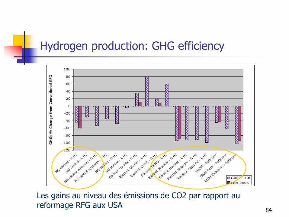
Les gains au niveau des émissions de CO2 par rapport au reformage RFG aux USA
Hydrogen production: GHG efficiency
84
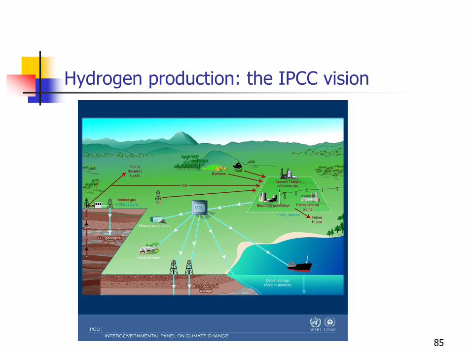
Hydrogen production: the IPCC vision
85

Hydrogen route
86
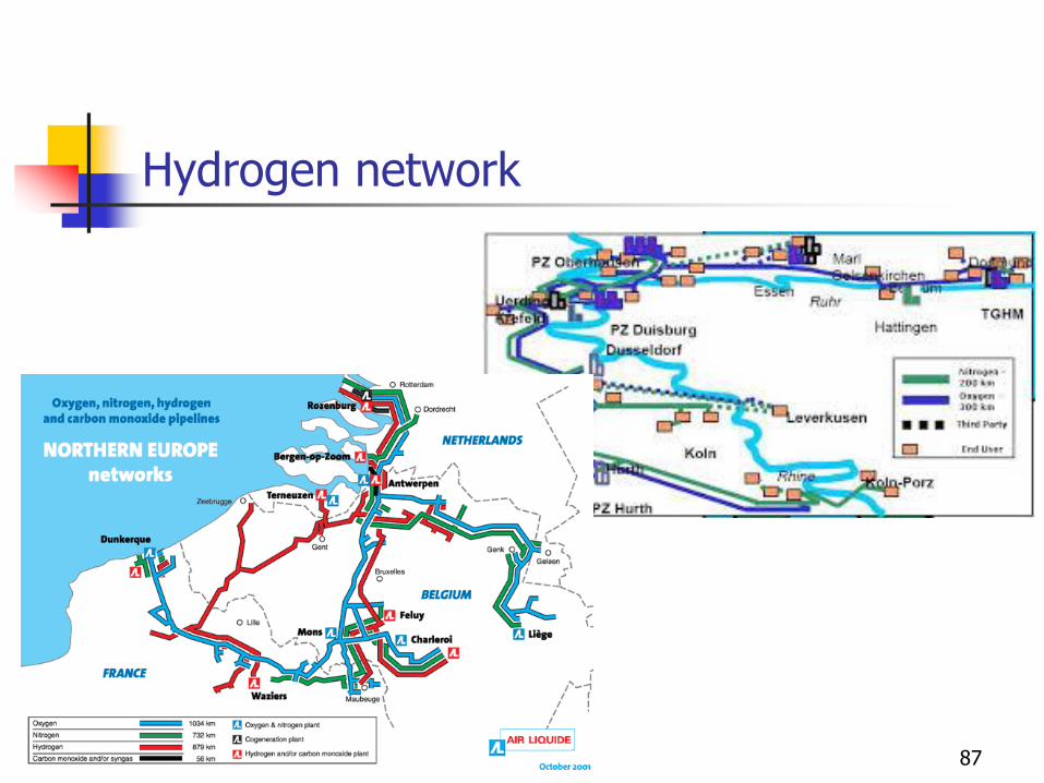
Hydrogen network
87
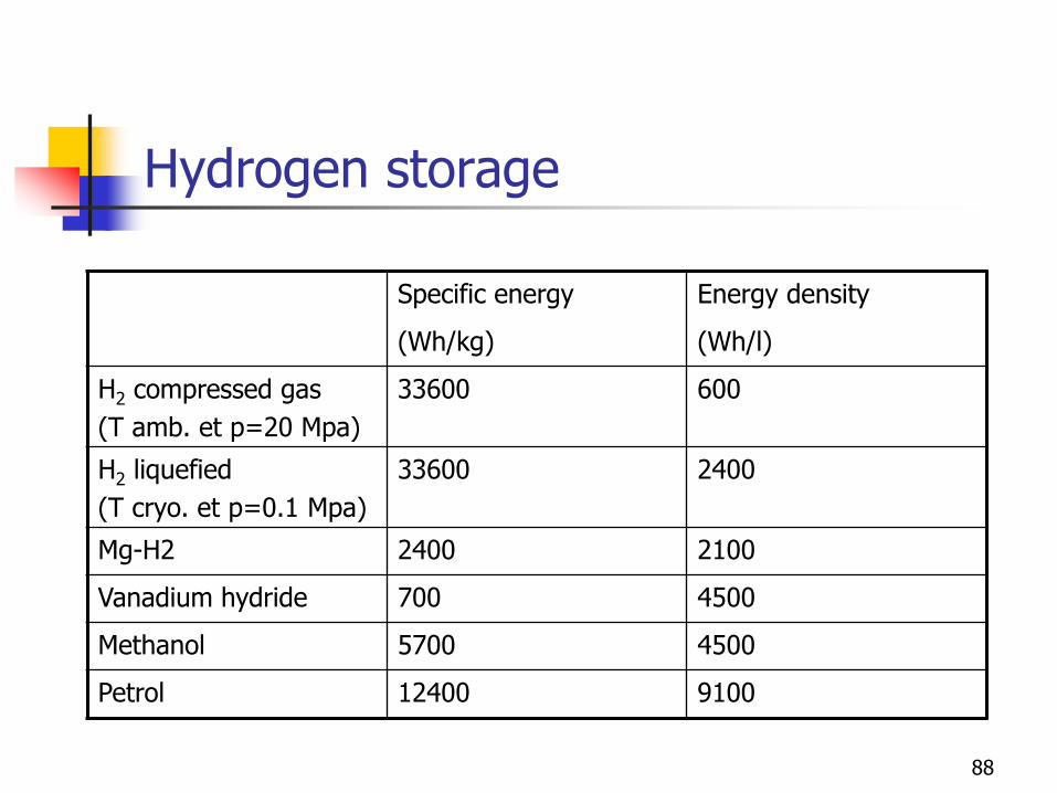
Hydrogen storage
Specific energy Energy density
(Wh/kg) (Wh/l)
H2 compressed gas
(T amb. et p=20 Mpa)
33600 600
H2 liquefied
(T cryo. et p=0.1 Mpa)
33600 2400
Mg-H2 2400 2100
Vanadium hydride 700 4500
Methanol 5700 4500
Petrol 12400 9100
88