fs728tp smart switch software administration manual · netgear does not assume any liability that...
TRANSCRIPT
FS728TP Smart Switch Software Administration Manual
202-10231-02December 2007
NETGEAR, Inc.4500 Great America ParkwaySanta Clara, CA 95054 USA

FS728TP Smart Switch FS728TP Smart Switch Software Administration Manual
© 2007 by NETGEAR, Inc. All Rights reserved
TrademarksNETGEAR and the NETGEAR logo are registered trademarks of NETGEAR, Inc. in the United States and/or other countries. Microsoft, Windows, and Windows NT are registered trademarks and Vista is a trademark of Microsoft Corporation. Other brand and product names are trademarks or registered trademarks of their respective holders.
Statement of ConditionsIn the interest of improving internal design, operational function, and/or reliability, NETGEAR reserves the right to make changes to the products described in this document without notice.NETGEAR does not assume any liability that may occur due to the use or application of the product(s) or circuit layout(s) described herein. Information is subject to change without notice.
Certificate of the Manufacturer/ImporterIt is hereby certified that the FS728TP 10/100 PoE Smart Switch with Gigabit Ports has been suppressed in accordance with the conditions set out in the BMPT-AmtsblVfg 243/1991 and Vfg 46/1992. The operation of some equipment (for example, test transmitters) in accordance with the regulations may, however, be subject to certain restrictions. Please refer to the notes in the operating instructions. The Federal Office for Telecommunications Approvals has been notified of the placing of this equipment on the market and has been granted the right to test the series for compliance with the regulations.
Voluntary Control Council for Interference (VCCI) StatementThis equipment is in the first category (information equipment to be used in commercial and/or industrial areas) and conforms to the standards set by the Voluntary Control Council for Interference by Data Processing Equipment and Electronic Office Machines that are aimed at preventing radio interference in commercial and/or industrial areas.Consequently, when this equipment is used in a residential area or in an adjacent area thereto, radio interference may be caused to equipment such as radios and TV receivers.
Federal Communications Commission (FCC) Compliance Notice: Radio Frequency NoticeThis device complies with part 15 of the FCC Rules. Operation is subject to the following two conditions:This device may not cause harmful interference.This device must accept any interference received, including interference that may cause undesired operation.
NOTE: This equipment has been tested and found to comply with the limits for a Class A digital device, pursuant to part 15 of the FCC Rules. These limits are designed to provide reasonable protection against harmful interference in a residential installation. This equipment generates, uses, and can radiate radio frequency energy and, if not installed and used in accordance with the instructions, may cause harmful interference to radio communications. However, there is no guarantee that interference will not occur in a particular installation. If this equipment does cause harmful interference to radio or television reception, which can be
ii
v1.0, December 2007

FS728TP Smart Switch FS728TP Smart Switch Software Administration Manual
determined by turning the equipment off and on, the user is encouraged to try to correct the interference by one or more of the following measures:
• Reorient or relocate the receiving antenna.• Increase the separation between the equipment and receiver.• Connect the equipment into an outlet on a circuit different from that which the receiver is connected.• Consult the dealer or an experienced radio/TV technician for help.
EU Statement of ComplianceThe NETGEAR FS728TP 10/100 PoE Smart Switch with Gigabit Ports is compliant with the following EU Council Directives: 89/336/EEC and LVD 73/23/EEC. Compliance is verified by testing to the following standards: EN55022 Class A, EN55024 and EN60950-1.
Canadian Department of Communications Radio Interference RegulationsThis digital apparatus (NETGEAR FS728TP Smart Switch) does not exceed the Class A limits for radio-noise emissions from digital apparatus as set out in the Radio Interference Regulations of the Canadian Department of Communications.
Règlement sur le brouillage radioélectrique du ministère des CommunicationsCet appareil numérique (NETGEAR FS728TP Smart Switch) respecte les limites de bruits radioélectriques visant les appareils numériques de classe A prescrites dans le Règlement sur le brouillage radioélectrique du ministère des Communications du Canada.
Customer SupportFor assistance with installing and configuring your NETGEAR system or for questions or problems following installation:• Check the NETGEAR Web page at http://www.NETGEAR.com/support• Call Technical Support in North America at 1-888-NETGEAR. If you are outside North America, please refer to
the phone numbers listed on the Support Information Card that was included with your switch.• Email Technical Support at [email protected].• Defective or damaged merchandise can be returned to your point-of-purchase representative.
Internet/World Wide WebNETGEAR maintains a World Wide Web home page that you can access at the uniform resource locator (URL) http://www.NETGEAR.com. A direct connection to the Internet and a Web browser such as Internet Explorer or Netscape are required.
Warning: This is a Class A product. In a domestic environment, this product may cause radio interference, in which case the user may be required to take appropriate measures.
iii
v1.0, December 2007

FS728TP Smart Switch FS728TP Smart Switch Software Administration Manual
FCC Requirements for Operation in the United StatesFCC Information to User: This product does not contain any user-serviceable components and is to be used with approved antennas only. Any product changes or modifications will invalidate all applicable regulatory certifications and approvalsFCC Guidelines for Human Exposure: This equipment complies with FCC radiation exposure limits set forth for an uncontrolled environment. This equipment should be installed and operated with a minimum distance of 20 cm between the radiator and your body. This transmitter must not be co-located or operating in conjunction with any other antenna or transmitter. FCC Declaration Of Conformity: We, NETGEAR, Inc., 4500 Great America Parkway, Santa Clara, CA 95054, declare under our sole responsibility that the model FS728TP 10/100 PoE Smart Switch with Gigabit Ports complies with Part 15 of FCC Rules. Operation is subject to the following two conditions: a) This device may not cause harmful interference and b) This device must accept any interference received, including interference that may cause undesired operation.”
Product and Publication Details
Model Number: FS728TP
Publication Date: December 2007
Product Family: Smart Switch
Product Name: FS728TP 10/100 PoE Smart Switch with Gigabit Ports
Home or Business Product: Business
Language: English
Publication Part Number: 202-10231-02
Publication Version Number: 1.0
iv
v1.0, December 2007

v
v1.0, December 2007

FS728TP Smart Switch FS728TP Smart Switch Software Administration Manual
Contents
FS728TP Smart Switch Software Administration Manual iWho Should Use this Book................................................................................................ xHow to Use This Book ....................................................................................................... xConventions, Formats, and Scope ................................................................................... xiHow to Use This Manual .................................................................................................. xiiHow to Print this Manual.................................................................................................. xiiiRevision History............................................................................................................... xiii
Chapter 1 Getting Started with Switch Management
System Requirements ....................................................................................................1-1Switch Management Interface ........................................................................................1-2Network with a DHCP Server .........................................................................................1-3Network without a DHCP Server ....................................................................................1-5
Manually Assigning Network Parameters ................................................................1-5NIC Setting on the Host that Accesses the FS728TP 10/100 PoE Smart Switch with Gigabit Ports ............................................................................................................1-6
Web Access ....................................................................................................................1-7Additional Utilities ...........................................................................................................1-8
Password Change ....................................................................................................1-8Firmware Upgrade ...................................................................................................1-9Exit .........................................................................................................................1-10
Chapter 2 Introduction to the Web Browser Interface
Logging Into the NETGEAR Home Screen ....................................................................2-1The Navigation Menu ...............................................................................................2-2
Using the NETGEAR Web Management System Options .............................................2-3Device Management Buttons ...................................................................................2-3Informational Services ..............................................................................................2-4
Contents vi
v1.0, December 2007

FS728TP Smart Switch FS728TP Smart Switch Software Administration Manual
Using Screen and Table Options ..............................................................................2-5Chapter 3 Managing System Settings
Using the System Settings Utility ....................................................................................3-1Management ...................................................................................................................3-1
System Information ..................................................................................................3-1IP Configuration .......................................................................................................3-3Time .........................................................................................................................3-4
Device View ....................................................................................................................3-7PoE .................................................................................................................................3-7
Basic ........................................................................................................................3-8Advanced .................................................................................................................3-9
SNMP ...........................................................................................................................3-13SNMPv1/v2 ............................................................................................................3-14SNMPv3 .................................................................................................................3-17
Chapter 4 Configuring Switching Settings
Configuring Switching Settings .......................................................................................4-1Ports ...............................................................................................................................4-1
Port Configuration ....................................................................................................4-1LAG ................................................................................................................................4-4
Basic ........................................................................................................................4-5Advanced .................................................................................................................4-8
VLAN ............................................................................................................................4-14Basic ......................................................................................................................4-14Advanced ...............................................................................................................4-16
STP ...............................................................................................................................4-22Basic ......................................................................................................................4-22Advanced ...............................................................................................................4-23
Multicast .......................................................................................................................4-28Basic ......................................................................................................................4-29Advanced ...............................................................................................................4-31
Address Table ...............................................................................................................4-37Basic ......................................................................................................................4-37Advanced ...............................................................................................................4-39
vii Contents
v1.0, December 2007

FS728TP Smart Switch FS728TP Smart Switch Software Administration Manual
Chapter 5 Configuring QoS
Configuring the Basic and Advanced QoS Settings .......................................................5-1CoS .................................................................................................................................5-1
Basic ........................................................................................................................5-2Advanced .................................................................................................................5-7
Chapter 6 Managing Security
Setting Security Configuration Options ...........................................................................6-1Management Security .....................................................................................................6-1
User Configuration ...................................................................................................6-1RADIUS ....................................................................................................................6-2TACACS+ .................................................................................................................6-4Authentication List ....................................................................................................6-6
Port Authentication .........................................................................................................6-7Basic ........................................................................................................................6-8Advanced .................................................................................................................6-9
Traffic Control ...............................................................................................................6-13Storm Control .........................................................................................................6-13Port Security ...........................................................................................................6-15
ACL ...............................................................................................................................6-17MAC ACL ...............................................................................................................6-18MAC Rules .............................................................................................................6-19MAC Binding Configuration ....................................................................................6-21IP ACL ....................................................................................................................6-22IP Rules ..................................................................................................................6-23IP Binding Configuration ........................................................................................6-25Binding Table ..........................................................................................................6-26
Chapter 7 Monitoring the Switch
Setting Monitoring Options .............................................................................................7-1Logs ................................................................................................................................7-1
Logs Configuration ...................................................................................................7-2Log Filter ..................................................................................................................7-3Memory Log .............................................................................................................7-4
Contents viii
v1.0, December 2007

FS728TP Smart Switch FS728TP Smart Switch Software Administration Manual
Flash Log .................................................................................................................7-6Server Log ................................................................................................................7-7
RMON .............................................................................................................................7-9Basic ........................................................................................................................7-9Advanced ............................................................................................................... 7-11
Port Mirroring ................................................................................................................7-22Port Mirroring .........................................................................................................7-23
Chapter 8 Maintenance
Using the Maintenance Options .....................................................................................8-1Reset ..............................................................................................................................8-1
Device Reboot ..........................................................................................................8-1Factory Default .........................................................................................................8-2
Upload ............................................................................................................................8-3Upload ......................................................................................................................8-3
Download ........................................................................................................................8-4Download .................................................................................................................8-4
File Management ............................................................................................................8-5Active Image ............................................................................................................8-5
Troubleshooting ..............................................................................................................8-6Diagnostics ...............................................................................................................8-6
Chapter 9 Online Help
Online Help .....................................................................................................................9-1Support ...........................................................................................................................9-1User Guide .....................................................................................................................9-2
Appendix A Default SettingsIndex
ix Contents
v1.0, December 2007

About This Manual
The NETGEAR® FS728TP Smart Switch FS728TP Smart Switch Software Administration Manual describes how to install, configure, operate, and troubleshoot the FS728TP 10/100 PoE Smart Switch with Gigabit Ports using its included software. This book describes the software configuration procedures and explains the options available within those procedures.
Who Should Use this Book
The information in this manual is intended for readers with intermediate to advanced system management skills.
This document was created primarily for the system administrator who wishes to install and configure the FS728TP Smart Switch in a network. This user guide assumes that the reader has a general understanding of switch platforms and a basic knowledge of Ethernet and networking concepts. To install this switch, it is not necessary to understand and use all of its capabilities. Once basic configuration is performed, the switch operates using the remaining factory default parameters. However, a greater level of configuration—anywhere from the basic up to the maximum possible—will allow your network the full benefit of the switch’s features. The web interface simplifies this configuration at all levels.
How to Use This Book
This document describes configuration commands for the FS728TP Smart Switch software. The commands can all be accessed from the Web interface.
• Chapter 1, “Getting Started with Switch Management” describes how to use the SmartWizard Discovery utility to set up your switch so that you can communicate with it.
• Chapter 2, “Introduction to the Web Browser Interface” introduces the Web browser interface.
• Chapter 3, “Managing System Settings” describes how to configure the System functions.
• Chapter 4, “Configuring Switching Settings” describes how to configure the Switching functions.
• Chapter 5, “Configuring QoS” describes how to configure QoS functions.
x
v1.0, December 2007

FS728TP Smart Switch FS728TP Smart Switch Software Administration Manual
• Chapter 6, “Managing Security” describes how to configure security.
• Chapter 7, “Monitoring the Switch” describes how to configure switch monitoring.
• Chapter 8, “Maintenance” describes the firmware upgrade procedure and reset functions.
• Chapter 9, “Online Help” describes how to obtain online help and support.
• Appendix A, “Default Settings” gives FS728TP Smart Switch specifications and lists default feature values.
Conventions, Formats, and Scope
The conventions, formats, and scope of this manual are described in the following paragraphs:
• Typographical Conventions. This manual uses the following typographical conventions:
• Formats. This manual uses the following formats to highlight special messages:
Note: Refer to the product release notes for the FS728TP Smart Switch Software application level code. The release notes detail the platform specific functionality of the Switching, SNMP, Config, and Management packages.
Italics Emphasis, books, CDs, file and server names, extensions
Bold User input, IP addresses, GUI screen text
Fixed Command prompt, CLI text, code
italics URL links
Note: This format is used to highlight information of importance or special interest.
Tip: This format is used to highlight a procedure that will save time or resources.
Warning: Ignoring this type of note may result in a malfunction or damage to the equipment.
xi About This Manual
v1.0, December 2007

FS728TP Smart Switch FS728TP Smart Switch Software Administration Manual
• Scope. This manual is written for the FS728TP Smart Switch according to these specifications:
.
How to Use This Manual
The HTML version of this manual includes the following:
• Buttons and for browsing forwards or backwards through the manual one page at a time.
• A button that displays the table of contents and a button. Double-click on a link in the table of contents or index to navigate directly to where the topic is described in the manual.
• A button to access the full NETGEAR, Inc. online knowledge base for the product model.
• Links to PDF versions of the full manual and individual chapters.
Danger: This is a safety warning. Failure to take heed of this notice may result in personal injury or death.
Product Version FS728TP 10/100 PoE Smart Switch with Gigabit Ports
Manual Publication Date December 2007
Note: Product updates are available on the NETGEAR, Inc. website athttp://www.netgear.com/support.
About This Manual xii
v1.0, December 2007

FS728TP Smart Switch FS728TP Smart Switch Software Administration Manual
How to Print this Manual
To print this manual, select one of the following options:
• Printing a Page from HTML. Each page in the HTML version of the manual is dedicated to a major topic. Select File > Print from the browser menu to print the page contents.
• Printing from PDF. Your computer must have the free Adobe Acrobat reader installed in order to view and print PDF files. The Acrobat reader is available on the Adobe Web site at http://www.adobe.com.
– Printing a PDF Chapter.
• Click the PDF of This Chapter link at the top left of any page in the chapter you want to print. The PDF version of the chapter you were viewing opens in a browser window.
• Click the print icon in the upper left of your browser window.
– Printing a PDF version of the Complete Manual.
• Click the Complete PDF Manual link at the top left of any page in the manual. The PDF version of the complete manual opens in a browser window.
• Click the print icon in the upper left of your browser window.
Revision History
Tip: If your printer supports printing two pages on a single sheet of paper, you can save paper and printer ink by selecting this feature.
Part Number Version Number Date Description
202-10231-02 1.0 May 2007 Product created
202-10231-02 1.0 December 2007 Feature update
xiii About This Manual
v1.0, December 2007

Chapter 1Getting Started with Switch Management
This section provides an overview of switch management, including the methods you can choose to start managing your NETGEAR FS728TP 10/100 PoE Smart Switch with Gigabit Ports. It also leads you through the steps necessary to get started, using the SmartWizard Discovery utility. The section includes this information under the following menu options:
• “System Requirements”
• “Switch Management Interface”
• “Network with a DHCP Server”
• “Network without a DHCP Server”
• “Web Access”
• “Additional Utilities”
System Requirements
The following hardware and software facilities are required to run the applications described in this manual:
• Network facilities:– Ethernet network with or without DHCP server as appropriate– Ethernet cable to connect the switch to a PC
• For running the SmartWizard Discovery utility and local or remote Web Management:– IBM-type PC with CD drive: RAM size and disk specification are not critical– OS software: Microsoft Windows Vista, Windows XP, or Windows 2000– Desktop computer running Microsoft Internet Explorer 5.0 or later or Netscape Navigator
6.0 or later, or equivalent
1-1
v1.0, December 2007

FS728TP Smart Switch FS728TP Smart Switch Software Administration Manual
Switch Management Interface
Your NETGEAR FS728TP 10/100 PoE Smart Switch with Gigabit Ports contains an embedded web server and management software for managing and monitoring switch functions. This switch operates as a simple switch without using the management software. The management software enables you to configure more advanced features, and consequently improve switch efficiency as well as overall network performance.
Web-Based Management enables you to monitor, configure, and control your switch remotely using a common web browser, instead of having to use expensive and complicated SNMP software products. Simply by using your web browser, you can monitor the performance of your switch and optimize network configuration. Using your browser, for example, you can set up VLANs, traffic priority, and configure port trunking.
In addition, NETGEAR provides the SmartWizard Discovery utility with this product. This program runs under Microsoft Windows XP or Windows 2000 and provides a “front end” that discovers the switches on your network segment. When you power up your switch for the first time, the SmartWizard Discovery utility enables you to configure its basic network parameters without prior knowledge of IP address or subnet mask. Following such configuration, this program leads you into the Web Management interface.
Some features of the SmartWizard Discovery utility and Web Management interface are shown in the table below.
Note: For complete hardware installation instructions, refer to the FS728TP Smart Switch Hardware Installation Manual included on your Resource CD, or go tohttp://www.netgear.com/support.
1-2 Getting Started with Switch Management
v1.0, December 2007

FS728TP Smart Switch FS728TP Smart Switch Software Administration Manual
For a more detailed discussion of the SmartWizard Discovery utility, continue with this section: “Network with a DHCP Server” or “Network without a DHCP Server”. For a detailed discussion of the Web Browser Interface, see Chapter 2, “Introduction to the Web Browser Interface”.
Network with a DHCP Server
To install the switch in a network with a DHCP server, proceed as follows:
1. Connect the FS728TP Smart Switch to a DHCP network.
2. Power on the switch by connecting its AC-DC power adapter.
3. Install the SmartWizard Discovery utility, located on the switch installation CD, on your computer.
4. Start the SmartWizard Discovery utility.
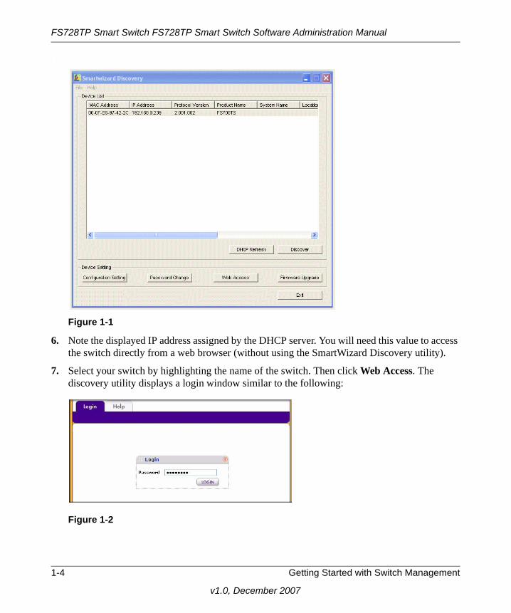
5. Click Discover for the SmartWizard Discovery utility to find your FS728TP 10/100 PoE Smart Switch with Gigabit Ports. You should see a screen similar to that shown below.
Table 1-1. Switch Management Methods
Management Method Features
SmartWizard Discovery utility No IP address or subnet mask setup neededDiscover all switches on the networkUser-friendly interface under Microsoft WindowsFirmware upgrade capabilityPassword change featureProvides entry to web configuration of switch
Web browser interface Password protectionIdeal for configuring the switch remotely Compatible with Internet Explorer and Netscape Navigator on any platformExtensive switch configuration possible Configuration backup and restoreCan be accessed from any location via the switch’s IP addressIntuitive browser interfaceMost visually appealing
Getting Started with Switch Management 1-3
v1.0, December 2007
FS728TP Smart Switch FS728TP Smart Switch Software Administration Manual
.
6. Note the displayed IP address assigned by the DHCP server. You will need this value to access the switch directly from a web browser (without using the SmartWizard Discovery utility).
7. Select your switch by highlighting the name of the switch. Then click Web Access. The discovery utility displays a login window similar to the following:
Figure 1-1
Figure 1-2
1-4 Getting Started with Switch Management
v1.0, December 2007

FS728TP Smart Switch FS728TP Smart Switch Software Administration Manual
8. Use your web browser to manage your switch. The default password is password. Then use this screen to proceed to management of the switch covered in Chapter 2, “Introduction to the Web Browser Interface”.
Network without a DHCP Server
This section describes how to set up your switch in a network without a DHCP server, and is divided into the following tasks:
• Manually assign network parameters for your switch
• Configure the NIC settings on the host PC
• Log in to the web-based switch management utility
Manually Assigning Network ParametersIf your network has no DHCP service, you must assign a static IP address to your switch. You can also assign the switch a static IP address even if your network has DHCP service. Proceed as follows:
1. Connect the FS728TP 10/100 PoE Smart Switch with Gigabit Ports to your existing network.
2. Power on the switch by plugging in the AC-DC power adapter. The default IP is 192.168.0.239.
3. Install the SmartWizard Discovery utility on your computer. The SmartWizard Discovery utility is located on the switch installation CD.
4. Start the SmartWizard Discovery utility.
5. Click Discover for the SmartWizard Discovery utility to find your FS728TP 10/100 PoE Smart Switch with Gigabit Ports. You should see a screen similar to that shown in Figure 1-1.
6. Click Configuration Setting. A screen similar to that shown below appears.
Getting Started with Switch Management 1-5
v1.0, December 2007

FS728TP Smart Switch FS728TP Smart Switch Software Administration Manual
.
7. Select Disable to disable DHCP.
8. The default IP address is 192.168.0.239 and the default subnet mask is 255.255.255.0. If you want different values, enter the switch IP address, gateway IP address and subnet mask.
9. Type your password and click Set. Please ensure that your PC and the FS728TP 10/100 PoE Smart Switch with Gigabit Ports are in the same subnet. Note the settings for later use.
NIC Setting on the Host that Accesses the FS728TP 10/100 PoE Smart Switch with Gigabit PortsThe settings of your Network Interface Card (NIC) under MS Windows OS are made with entries into Windows screens similar to the ones shown below. For comparison, the settings screens of the switch are also shown although they do not appear in the Windows view.
Figure 1-3
1-6 Getting Started with Switch Management
v1.0, December 2007

FS728TP Smart Switch FS728TP Smart Switch Software Administration Manual
You need Windows Administrator privileges to change these settings.
1. On your PC, access the MS Windows operating system TCP/IP Properties.
2. Set IP address and subnet mask appropriately. The subnet mask value is identical to that set in the switch. The PC IP address must be different from that of the switch but lie in the same subnet.
3. Click Web Access in the SmartWizard Discovery utility to enable the management screens as described in the following section.
Web Access
For Web access, you can either:
• Select Web Access using the SmartWizard Discovery utility (see “Network with a DHCP Server” or “Network without a DHCP Server”).
• Access the switch directly, without using the SmartWizard Discovery utility.
Figure 1-4
Getting Started with Switch Management 1-7
v1.0, December 2007

FS728TP Smart Switch FS728TP Smart Switch Software Administration Manual
You must work from the same network segment that contains the switch (i.e., the subnet mask values of switch and PC host must be the same) and you must point your browser using the switch IP address. If you used the SmartWizard Discovery utility to set up IP address and subnet mask, either with or without DHCP server, use that IP address in your browser window.
If you are starting with an “out of the box” switch and are not using the SmartWizard Discovery utility, you must initially configure your host PC to be on a network segment to match the default parameters of the switch, which are:
• IP address: 192.168.0.239
• Subnet Mask: 255.255.255.0
You can change the network parameters to match those of your network (this procedure is described in Chapter 3, “Managing System Settings”). Your host PC network parameters must then be set to match your network.
Clicking Web Access on the SmartWizard Discovery utility or accessing the switch directly displays the screen shown below..
Use this screen to proceed to management of the switch covered in Chapter 2, “Introduction to the Web Browser Interface”.
Additional Utilities
Alternatively, from the main screen shown on Figure 1-1 you can access these additional functions:
• “Password Change”
• “Firmware Upgrade”
Password ChangeYou can set a new password of up to 20 ASCII characters.
1. Click Password Change from the Switch Setting section. The Password Change screen appears. You can set a new password. You must enter the old and new passwords and confirm the new one.
2. Click Set to enable the new password.
1-8 Getting Started with Switch Management
v1.0, December 2007

FS728TP Smart Switch FS728TP Smart Switch Software Administration Manual
Firmware UpgradeThe FS728TP Smart Switch software is upgradeable, and enables your switch to take advantage of improvements and additional features as they become available. The upgrade procedure assumes that you have downloaded or otherwise obtained the firmware upgrade and that you have it available as a binary file on your computer. This procedure uses the TFTP protocol to implement the transfer from computer to switch..
If you click Firmware Upgrade from the main screen (see Figure 1-1), after you have selected the switch to upgrade, the following screen appears:.
1. Enter the following values into the appropriate places in the form:
• Product Assigned Firmware: The location of the new firmware. If you do not know the location, click Browse to locate the file.
• Upgrade Password: Enter your password; the default password is password.
Note: You can also upgrade the firmware using the Download menu of the switch (see “Download”).
Figure 1-5
Getting Started with Switch Management 1-9
v1.0, December 2007

FS728TP Smart Switch FS728TP Smart Switch Software Administration Manual
2. Click Apply to apply the settings to the Upgrade Configuration.
3. Click Start Upgrade to begin loading the upgrade. The system software is automatically loaded. The Upgrade State field shows upgrading in progress.When the process is complete, the switch automatically reboots.
ExitClick Exit from the SmartWizard Discovery screen to close the SmartWizard Discovery utility.
1-10 Getting Started with Switch Management
v1.0, December 2007
Chapter 2Introduction to the Web Browser Interface
This section introduces the web browser interface that enables you to configure and manage your NETGEAR FS728TP 10/100 PoE Smart Switch with Gigabit Ports. Your FS728TP Smart Switch provides a built-in browser interface that enables you to configure and manage it remotely using a standard Web browser such as Microsoft Internet Explorer or Netscape Navigator. Online Help is also provided for many of the basic functions and features of the switch.
This section introduces the areas of the browser interface and includes the following topics:
• “Logging Into the NETGEAR Home Screen”
• “Using the NETGEAR Web Management System Options”
Logging Into the NETGEAR Home Screen
Begin your overview of the FS728TP Smart Switch browser interface by logging in:
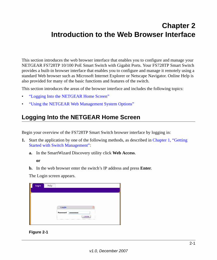
1. Start the application by one of the following methods, as described in Chapter 1, “Getting Started with Switch Management”:
a. In the SmartWizard Discovery utility click Web Access.
or
b. In the web browser enter the switch’s IP address and press Enter.
The Login screen appears.
Figure 2-1
2-1
v1.0, December 2007

FS728TP Smart Switch FS728TP Smart Switch Software Administration Manual
2. Enter the password (the factory default is password) and click Login. The home screen of the FS728TP Smart Switch browser interface displays.
The Navigation MenuAs shown below, logging in brings you to the view of the web browser interface.
The NETGEAR FS728TP web browser interface contains the following views:
Main Navigation Area – Located on the top of the NETGEAR FS728TP web browser interface and marked as 1 in Figure 2-2. The Main Navigation Area includes Primary and Secondary Navigation Bars. The Primary Navigation Bar contains a list of the different features that can be configured including System, Switching, QoS, Security, Monitoring, Maintenance and Help. Each feature expands to a subset of features that can be configured as part of the Secondary Navigation Bar.
Left Navigation Tree – Located on the left side of the NETGEAR FS728TP web browser interface and marked as 2 in Figure 2-2. For each Secondary Navigation Feature the Left Navigation Tree contains a subset of features that can be expanded to display all the components.
Figure 2-2
2-2 Introduction to the Web Browser Interface
v1.0, December 2007

FS728TP Smart Switch FS728TP Smart Switch Software Administration Manual
Work Area – Located on the right side of the NETGEAR FS728TP web browser interface and marked as 3 in Figure 2-2. The Work Area contains device tables, general device information, and configurable device parameters.
For further description of the functions, refer to the appropriate section of this manual:
• Chapter 3, “Managing System Settings” describes how to configure the System functions.
• Chapter 4, “Configuring Switching Settings” describes how to configure the Switch functions.
• Chapter 5, “Configuring QoS” describes how to configure QoS functions.
• Chapter 6, “Managing Security” describes how to configure security.
• Chapter 7, “Monitoring the Switch” describes how to configure monitoring functions.
• Chapter 8, “Maintenance” describes maintenance functions, such as firmware upgrade.
• Chapter 9, “Online Help” describes how to obtain online help and support.
Using the NETGEAR Web Management System Options
The FS728TP web browser interface provides the following options:
• Device Management Buttons – Provides an explanation of the management buttons in the NETGEAR FS728TP Smart Switch.
• Informational Services – Provides access to informational services including technical support, online help and device information.
• Using Screen and Table Options – Provides an explanation of specific GUI characteristics and tables for configuring the device.
Device Management ButtonsThe NETGEAR FS728TP Smart Switch web browser GUI management buttons allow network managers to easily configure the device from remote locations. The management buttons are shown below:
Table 2-1. Device Management Buttons
Button Name Description
Add Adds information to tables or information windows.
Apply Applies configured changes to the device.
CANCEL Cancels modifications to tables or information windows.
Introduction to the Web Browser Interface 2-3
v1.0, December 2007

FS728TP Smart Switch FS728TP Smart Switch Software Administration Manual
Informational ServicesInformational services provide access to technical support, online help and device information and are displayed in the following topics:
• “Help Navigation Tab”
• “Accessing Device Information”
Help Navigation TabThe Help Navigation Tab provides access to informational services including NETGEAR online support and an online user guide in PDF format. For a detailed description of how to access and use these functions, see Chapter 9, “Online Help”.
Accessing Device InformationEach screen of the web browser interface contains a help file with configuration information relating to the selected screen.
CLEAR ALL Refreshes device information.
CLEAR ALL COUNTERS Resets statistics counters.
CLEAR LOGS Clears logs.
CURRENT MEMBERS Displays current members of a LAG.
Delete Deletes information from tables or information windows.
GO Selects the specified interface.
REFRESH Refreshes the screen with current data.
TAGGED PORT MEMBERS Displays tagged port members of a VLAN.
TEST Tests copper cables.
UNTAGGED PORT MEMBERS Displays untagged port members of a VLAN.
Table 2-1. Device Management Buttons (continued)
Button Name Description
2-4 Introduction to the Web Browser Interface
v1.0, December 2007

FS728TP Smart Switch FS728TP Smart Switch Software Administration Manual
To access the help file for a screen:
1. Click the encircled red Question Mark icon, shown in the example below.
A help window for the screen opens.
Using Screen and Table OptionsThe NETGEAR FS728TP web browser interface contains screens and tables for configuring devices. This section describes the table options:
• “Selecting an Entry”
Figure 2-3
Figure 2-4
Introduction to the Web Browser Interface 2-5
v1.0, December 2007

FS728TP Smart Switch FS728TP Smart Switch Software Administration Manual
• “Adding an Entry”
• “Modifying an Entry”
• “Deleting an Entry”
• “Special Table Options”
Selecting an EntryTo select an entry:
1. Check the entry’s Select box. The selected entry is highlighted and the information appears in the first row, which contains the editable fields.
To select all entries:
1. Check the Select box in the first row to select all entries in the table. Fields that are unique are grayed out and displayed as read-only fields.
Adding an EntryAn entry may be added to the table by creating a new entry or by duplicating an existing entry.
Figure 2-5
Figure 2-6
2-6 Introduction to the Web Browser Interface
v1.0, December 2007

FS728TP Smart Switch FS728TP Smart Switch Software Administration Manual
To add an entry by creating a new entry in the table:
1. Enter the fields for the new entry in the provided fields in the first row.
2. Click Add to update the device. The new entry is displayed.
Modifying an EntryAn entry may be modified by editing its values in the first row.
To modify an entry:
1. Select the entry to be modified. Its contents are displayed in the first row.
2. Modify the fields in the first row.
3. Click Apply to update the device.
Deleting an EntryTo delete entries from a table:
1. Select the entries to be deleted.
Figure 2-7
Figure 2-8
Figure 2-9
Introduction to the Web Browser Interface 2-7
v1.0, December 2007

FS728TP Smart Switch FS728TP Smart Switch Software Administration Manual
2. Click Delete to update the device.
Special Table OptionsThe NETGEAR web browser interface tables have a unique GUI design which includes the following options:
• Gold Buttons
• Quick Boxes
• Interface View and Selection
Gold Buttons. Gold Buttons provide flexibility in viewing and configuring VLANs/LAGs on a port level. The following example displays gold button basic usage options.
To view the LAG configuration of the ports:
1. Click anywhere on the ports gold button. The ports panel is displayed:
2. Select the ports to be added as LAG members within the selected LAG by clicking on their respective boxes.
3. Click Apply to update the device.
Quick Boxes. Quick Boxes provide users with flexibility in configuring VLANs for all ports (on a stacking unit level) or LAGs. Clicking on the quick box toggles between the various options that exist for this field. A quick box appears to the right of the arrow on the left-hand side of the gold button. The following example displays quick box basic usage options.
Figure 2-10
2-8 Introduction to the Web Browser Interface
v1.0, December 2007
FS728TP Smart Switch FS728TP Smart Switch Software Administration Manual
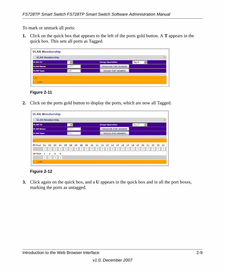
To mark or unmark all ports:
1. Click on the quick box that appears to the left of the ports gold button. A T appears in the quick box. This sets all ports as Tagged.
2. Click on the ports gold button to display the ports, which are now all Tagged.
3. Click again on the quick box, and a U appears in the quick box and in all the port boxes, marking the ports as untagged.
Figure 2-11
Figure 2-12
Introduction to the Web Browser Interface 2-9
v1.0, December 2007

FS728TP Smart Switch FS728TP Smart Switch Software Administration Manual
4. Click again on the quick box, and the quick box and all the port boxes appear blank, marking the ports as neither tagged nor untagged.
5. You may click on individual port boxes to toggle their tagged/untagged status
Interface View and Selection. A port or LAG interface may be selected from a table by using the interface selection row, located above the row of column headers. Clicking on PORTS or LAGS displays the ports or the LAGs:
Figure 2-13
2-10 Introduction to the Web Browser Interface
v1.0, December 2007

FS728TP Smart Switch FS728TP Smart Switch Software Administration Manual
To display all ports:
1. Click PORTS in the interface selection row. The screen displays a table of all ports.
To display all interfaces:
1. Click All in the interface selection row. A confirmation window opens.
2. Click OK. The screen displays a table of all interfaces.
Figure 2-14
Figure 2-15
Introduction to the Web Browser Interface 2-11
v1.0, December 2007

FS728TP Smart Switch FS728TP Smart Switch Software Administration Manual
To display the LAG table:
1. Click LAGS in the interface selection row. The screen displays a table of all LAGs.
To select an interface:
1. Enter the number of the interface in the GO TO INTERFACE box.
2. Click GO to select the interface, as in the following example.
Figure 2-16
2-12 Introduction to the Web Browser Interface
v1.0, December 2007

FS728TP Smart Switch FS728TP Smart Switch Software Administration Manual
Figure 2-17
Introduction to the Web Browser Interface 2-13
v1.0, December 2007

Chapter 3Managing System Settings
Using the System Settings Utility
The navigation pane at the top of the web browser interface contains a System tab that enables you to manage your FS728TP Smart Switch with features under the following main menu options:
• “Management”
• “Device View”
• “PoE”
• “SNMP”
The description that follows in this chapter describes configuring and managing system settings in the FS728TP Smart Switch.
Management
The Management menu enables configuration of some system parameters, the switch IP Address and the system time, and contains the following options:
• “System Information”
• “IP Configuration”
• “Time”
System InformationThe System Information screen contains parameters for configuring general device information including the system name, system location, system contact, and idle timeout.
3-1
v1.0, December 2007

FS728TP Smart Switch FS728TP Smart Switch Software Administration Manual
To configure system parameters:
1. Click System > Management > System Information. The System Information screen displays:
The System Information screen contains the following fields:
• System Name – Enter the user-defined device name. The field may contain 0-160 characters.
• System Location – Enter the location where the system is currently running. The field may contain 0-160 characters.
• System Contact – Enter the name of the contact person. The field may contain 0-160 characters.
• System Object ID – Displays the vendor’s authoritative identification of the network management subsystem contained in the entity.
• Date & Time – Displays the current date and local time.
Figure 3-1
Managing System Settings 3-2
v1.0, December 2007

FS728TP Smart Switch FS728TP Smart Switch Software Administration Manual
• System Up Time – Displays the amount of time since the most recent device reset. The system time is displayed in the following format: days, hours, minutes, seconds. For example, 41 days, 2 hours, 22 minutes, 15 seconds.
• Idle Timeout – Enter the amount of time (minutes) that elapses before an idle station is timed out. Idle stations that are timed out must login to the system. The field range is 5 - 30 minutes. The field default value is 10 minutes.
• Base MAC Address – Displays the MAC address of a standalone device.
• Serial Number – Displays the device serial number.
The Versions Table displays the following fields:
• Model Name – Displays the device model name.
• Hardware Version – Displays the installed device hardware version number.
• Boot Version – Displays the current boot version running on the device.
• Software Version – Displays the installed software version number.
2. Enter the System Name, System Location, System Contact and Idle Timeout in the provided fields.
3. Click Apply to update the system settings.
IP ConfigurationThe IP Configuration screen contains fields for assigning IP addresses. IP addresses are either defined as static or are retrieved using the Dynamic Host Configuration Protocol (DHCP). The IP Interface screen also contains information for defining default gateways DHCP and is also configured from the IP Interface screen. The DHCP assigns dynamic IP addresses to devices on a network. DHCP ensures that network devices can have a different IP address every time the device connects to the network.
Note the following when configuring IP Addresses:
• If the device is accessed using SmartWizard Discovery, the IP address retrieved through DHCP is displayed.
• If the device fails to retrieve an IP address through DHCP, the default IP address is 192.168.0.239.
3-3 Managing System Settings
v1.0, December 2007

FS728TP Smart Switch FS728TP Smart Switch Software Administration Manual
To define an IP interface:
1. Click System > Management > IP Configuration. The IP Configuration screen displays:
The IP Configuration screen contains the following fields:
• Dynamic IP Address (DHCP) – Enable the IP address to be configured automatically by the DHCP server. Selecting this field disables the IP Address, Subnet Mask, Gateway and Delete fields.
• Static IP Address – Enable the user to define a static IP address.
• IP Address – Enter the static IP address used to manage the device.
• Subnet Mask – Enter the IP address mask.
• Gateway – Enter the default gateway IP address. The following option is available:
– Delete – Delete the default gateway IP address.
2. Select the method of assigning the IP address by selecting either Dynamic IP Address or Static IP Address.
3. If you selected Static IP Address, enter the IP Address, Subnet Mask and Gateway address in the provided fields.
4. Click Apply to update the system settings.
TimeThe Time menu enables local system time or SNTP server configuration, and contains the following options:
• “Time Configuration”
Figure 3-2
Managing System Settings 3-4
v1.0, December 2007
FS728TP Smart Switch FS728TP Smart Switch Software Administration Manual
• “SNTP Server Configuration”
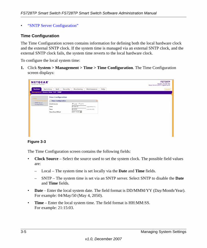
Time ConfigurationThe Time Configuration screen contains information for defining both the local hardware clock and the external SNTP clock. If the system time is managed via an external SNTP clock, and the external SNTP clock fails, the system time reverts to the local hardware clock.
To configure the local system time:
1. Click System > Management > Time > Time Configuration. The Time Configuration screen displays:
The Time Configuration screen contains the following fields:
• Clock Source – Select the source used to set the system clock. The possible field values are:
– Local – The system time is set locally via the Date and Time fields.
– SNTP – The system time is set via an SNTP server. Select SNTP to disable the Date and Time fields.
• Date – Enter the local system date. The field format is DD/MMM/YY (Day/Month/Year). For example: 04/May/50 (May 4, 2050).
• Time – Enter the local system time. The field format is HH:MM:SS. For example: 21:15:03.
Figure 3-3
3-5 Managing System Settings
v1.0, December 2007

FS728TP Smart Switch FS728TP Smart Switch Software Administration Manual
• Time Zone Offset – Select the difference between Greenwich Mean Time (GMT) and local time. For example, the Time Zone Offset for Paris is GMT +1, while the Time Zone Offset for New York is GMT –5.
2. Select the Clock Source by selecting either Local or SNTP.
3. If you selected Local, then enter the local Date and Time in the provided fields.
4. Select the Time Zone Offset from the list.
5. Click Apply to update the system settings.
SNTP Server ConfigurationThe SNTP Server Configuration screen allows network administrators to define primary and secondary SNTP servers. The system time is first retrieved through the primary SNTP server. If the device is unable to retrieve the system time through the primary server, the device retrieves the system time from the secondary server.
To configure SNTP servers:
1. Click System > Management > Time > SNTP Server Configuration. The SNTP Server Configuration screen displays:
The SNTP Server Configuration screen contains the following fields:
• SNTP Server 1 – Enter the primary SNTP server IP address. The Primary SNTP server is the first server used to retrieve the system time. The following option is available:
– Delete – Remove the currently configured SNTP Server 1.
Note: If you selected SNTP, you must configure the SNTP servers. See “SNTP Server Configuration” for detailed instructions on configuring the SNTP servers.
Figure 3-4
Managing System Settings 3-6
v1.0, December 2007
FS728TP Smart Switch FS728TP Smart Switch Software Administration Manual
• SNTP Server 2 – Enter the secondary SNTP server IP address. The Secondary SNTP server retrieves the system time if the Primary SNTP server times out. The following option is available:
– Delete – Remove the currently configured SNTP Server 2.
2. Enter the SNTP Server 1 and SNTP Server 2 in the provided fields.
3. Click Apply to update the system settings.
To remove SNTP servers:
1. Check the Delete box for each SNTP server that is to be removed.
2. Click Apply to update the system settings.
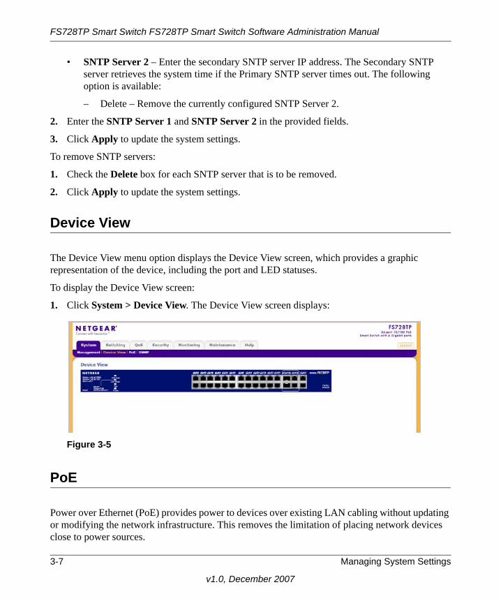
Device View
The Device View menu option displays the Device View screen, which provides a graphic representation of the device, including the port and LED statuses.
To display the Device View screen:
1. Click System > Device View. The Device View screen displays:
PoE
Power over Ethernet (PoE) provides power to devices over existing LAN cabling without updating or modifying the network infrastructure. This removes the limitation of placing network devices close to power sources.
Figure 3-5
3-7 Managing System Settings
v1.0, December 2007

FS728TP Smart Switch FS728TP Smart Switch Software Administration Manual
Power over Ethernet can be used in the following applications:
• IP Phones
• Wireless Access Points
• IP Gateways
• Audio and video remote monitoring
Powered Devices are devices that receive power from the device power supply, for example IP phones.
The PoE menu contains the following options:
• “Basic”
• “Advanced”
BasicThe PoE Basic menu contains the following option:
• “PoE Configuration”
PoE ConfigurationThe Basic PoE Configuration screen contains system PoE information for enabling PoE on the device, monitoring the current power usage, and enabling PoE traps.
To configure PoE on the device:
1. Click System > PoE > Basic > PoE Configuration. The Basic PoE Configuration screen displays:
Figure 3-6
Managing System Settings 3-8
v1.0, December 2007

FS728TP Smart Switch FS728TP Smart Switch Software Administration Manual
The Basic PoE Configuration screen contains the following fields:
• Power Status – Displays the online power source status. The possible field values are:
– On – The power supply unit is functioning.
– Off – The power supply unit is not functioning.
– Faulty – The power supply unit is functioning, but an error has occurred. For example, a power overload or a short circuit.
• Nominal Power – Displays the actual amount of power the device can supply. The field value is displayed in Watts.
• Consumed Power – Displays the amount of the power used by the device. The field value is displayed in Watts.
• System Usage Threshold – Enter the percentage of power consumed before an alarm is generated. The field value is 1-99 percent. The default is 95 percent.
• Traps – Select the PoE device trap state. The possible field values are:
– Enable – Enable PoE traps on the device.
– Disable – Disable PoE traps on the device. This is the default value.
2. Enter the System Usage Threshold in the provided field.
3. Select either Enable or Disable in the Traps field.
4. Click Apply to update the device.
AdvancedThe PoE Advanced menu contains the following options:
• “PoE Configuration”
• “PoE Port Configuration”
PoE ConfigurationThe Advanced PoE Configuration screen contains system PoE information for enabling PoE on the device, monitoring the current power usage, and enabling PoE traps.
3-9 Managing System Settings
v1.0, December 2007

FS728TP Smart Switch FS728TP Smart Switch Software Administration Manual
To configure PoE on the device:
1. Click System > PoE > Advanced > PoE Configuration. The Advanced PoE Configuration screen displays:
The PoE Configuration screen contains the following fields:
• Power Status – Displays the online power source status. The possible field values are:
– On – The power supply unit is functioning.
– Off – The power supply unit is not functioning.
– Faulty – The power supply unit is functioning, but an error has occurred. For example, a power overload or a short circuit.
• Nominal Power – Displays the actual amount of power the device can supply. The field value is displayed in Watts.
• Consumed Power – Displays the amount of the power used by the connecting device. The field value is displayed in Watts.
• System Usage Threshold – Enter the percentage of power consumed before an alarm is generated. The field value is 1-99 percent. The default is 95 percent.
• Traps – Select the PoE device trap state. The possible field values are:
– Enable – Enable PoE traps on the device.
– Disable – Disable PoE traps on the device. This is the default value.
2. Enter the System Usage Threshold in the provided field.
3. Select the Traps mode from the list in the provided field.
4. Click Apply to update the device.
Figure 3-7
Managing System Settings 3-10
v1.0, December 2007

FS728TP Smart Switch FS728TP Smart Switch Software Administration Manual
PoE Port ConfigurationThe PoE Interface Configuration screen contains system PoE information for enabling PoE on the device, monitoring the current power usage, and enabling PoE traps.
To enable PoE on the device:
1. Click System > PoE > Advanced > PoE Port Configuration. The PoE Port Configuration screen displays:
The PoE Port Configuration screen contains the following fields:
• Interface – Displays the specific interface for which PoE parameters are defined. PoE parameters are assigned to the powered device that is connected to the selected interface.
• Admin Mode – Select the device PoE mode. The possible field values are:
– Enable – Enable the Device Discovery protocol and provides power to the device using the PoE module. The Device Discovery Protocol enables the device to discover Powered Devices attached to the device interfaces and to learn their classification. This is the default setting.
– Disable – Disable the Device Discovery protocol and stops the power supply to the device using the PoE module.
Figure 3-8
3-11 Managing System Settings
v1.0, December 2007

FS728TP Smart Switch FS728TP Smart Switch Software Administration Manual
• Priority Level – Select the port priority if the power supply is low. The field default is low. For example, if the power supply is running at 99% usage, and port 1 is prioritized as high, but port 3 is prioritized as low, port 1 is prioritized to receive power and port 3 may be denied power. The possible field values are:
– Low – Set the PoE priority level as low. This is the default level.
– Medium – Set the PoE priority level as medium.
– High – Set the PoE priority level as high.
• Class – Displays the classification of the powered device. The class defines the maximum power that can be provided to the powered device. The possible field values are:
– Class 0 – The minimum power level at the Power Sourcing Equipment is 15.4 Watts.
– Class 1 – The minimum power level at the Power Sourcing Equipment is 4.0 Watts.
– Class 2 – The minimum power level at the Power Sourcing Equipment is 7.0 Watts.
– Class 3 – The minimum power level at the Power Sourcing Equipment is 15.4 Watts.
– Class 4 – Treated as Class 0.
• Output Voltage – Displays the Output Voltage in Volts.
• Output Current – Displays the Output current in milliamps.
• Output Power – Displays the Output power in Watts.
• Power Limit – Displays the power limit in Watts.
• Status – Displays the port’s PoE status. The possible field values are:
– On – The device is enabled to deliver power via the interface.
– Off – The device is disabled for delivering power via the interface.
– Test Fail – The powered device test has failed. For example, a port could not be enabled and cannot be used to deliver power to the powered device.
– Testing – The powered device is being tested. For example, a powered device is tested to confirm it is receiving power from the power supply.
– Searching – The device is currently searching for a powered device. Searching is the default PoE operational status.
– Fault – The device has detected a fault on the powered device. For example, the powered device memory could not be read.
2. Select an interface.
Managing System Settings 3-12
v1.0, December 2007
FS728TP Smart Switch FS728TP Smart Switch Software Administration Manual
3. Select the Admin Mode and Priority Level from the lists in the provided fields in the first row.
4. Click Apply to update the device
SNMP
Simple Network Management Protocol (SNMP) provides a method for managing network devices. The device supports the following SNMP versions:
• SNMP v1 and v2c
• SNMP version 3
The SNMP agents maintain a list of variables that are used to manage the device. The variables are defined in the Management Information Base (MIB). The SNMP agent defines the MIB specification format, as well as the format used to access the information over the network. Access strings control access rights to the SNMP agents. SNMP v3 applies access control and a new traps mechanism. In addition, User Security Model (USM) parameters are defined for SNMPv3, including:
• Authentication – Provides data integrity and data origin authentication.
• Privacy – Protects against the disclosure of message content. Cipher Block-Chaining (CBC) is used for encryption. Either authentication is enabled on an SNMP message, or both authentication and privacy. However, privacy cannot be enabled without authentication.
• Timeliness – Protects against message delay or message redundancy. The SNMP agent compares the incoming message to the message time information. Enter the amount of time the device waits before re-sending informs.
• Key Management – Enter key generation, key updates, and key usage.
The device supports SNMP notification filters based on Object IDs (OIDs). OIDs are used by the system to manage device features. SNMP v3 supports the following features:
• Security
• Feature Access Control
• Traps. The device generates copy traps.
The SNMP menu contains the following options:• “SNMPv1/v2”• “SNMPv3”
3-13 Managing System Settings
v1.0, December 2007

FS728TP Smart Switch FS728TP Smart Switch Software Administration Manual
SNMPv1/v2The SNMPv1/v2 menu contains the following options:
• “Community Configuration”
• “Trap Configuration”
Community ConfigurationAccess rights are managed by defining communities in the Community Configuration screen. When community names are changed, access rights are also modified.
To configure SNMP communities:
1. Click System > SNMP > SNMPv1/v2 > Community Configuration. The Community Configuration screen displays:
The Community Configuration screen contains the following fields:
• Management Station – Enter the management station IP address for which the Basic SNMP community is defined.
• Community String – Enter the password used to authenticate the management station to the device.
• Access Mode – Select the access rights of the community. The possible field values are:
– Read Only – Management access is restricted to read-only. Changes cannot be made to the device configuration and to the community.
– Read Write – Management access is read-write. Changes can be made to the device configuration but not to the community.
Figure 3-9
Managing System Settings 3-14
v1.0, December 2007

FS728TP Smart Switch FS728TP Smart Switch Software Administration Manual
– SNMP Admin – User has access to all device configuration options, as well as permissions to modify the community.
2. Select the community entry.
3. Enter the Management Station and Community String in the provided fields in the first row.
4. Select the Access Mode from the list in the provided field in the first row.
5. Click Apply to update the device.
To add a new SNMP community:
1. Click System > SNMP > SNMPv1/v2 > Community Configuration. The Community Configuration screen displays.
2. Enter the Management Station and Community String in the provided fields in the first row.
3. Select the Access Mode from the list in the provided field in the first row.
4. Click Add to update the device.
To remove an SNMP community:
1. Click System > SNMP > SNMPv1/v2 > Community Configuration. The Community Configuration screen displays.
2. Select the entry to be removed.
3. Click Delete to remove the entry.
Trap ConfigurationThe SNMPv1/v2 Trap Configuration screen contains information for defining filters that determine whether traps are sent to specific users, and the trap type sent. SNMP notification filters provide the following services:
• Identifying Management Trap Targets
• Defining Trap Filtering
• Defining Trap Generation Parameters
• Providing Access Control Checks
3-15 Managing System Settings
v1.0, December 2007

FS728TP Smart Switch FS728TP Smart Switch Software Administration Manual
To configure SNMPv1/v2 trap station management:
1. Click System > SNMP > SNMPv1/v2 > Trap Configuration. The SNMPv1/v2 Trap Configuration screen displays:
The SNMPv1/v2 Trap Configuration screen contains the following fields:
• Recipients IP – Enter the IP address to which the traps are sent.
• Notification Type – (Configurable only if the Notification Version is SNMPv2.) Select the type of notification sent. The possible field values are:
– Traps – Traps are sent.
– Informs – Informs are sent only when SNMPv2 is enabled.
• Community String – Enter the community string of the trap manager.
• Notification Version – Select the trap type. The possible field values are:
– SNMPv1 – SNMP Version 1 traps are sent.
– SNMPv2 – SNMP Version 2c traps are sent.
• UDP Port – Enter the UDP port used to send notifications. The default UDP port is 162.
• Timeout – Enter the amount of time (in seconds) the device waits before re-sending informs. The default is 15 seconds.
• Retries – Enter the amount of times the device re-sends an inform request. The default is 3 seconds.
2. Select the trap entry.
3. Enter the fields in the first row.
4. Click Apply to update the device.
Figure 3-10
Managing System Settings 3-16
v1.0, December 2007

FS728TP Smart Switch FS728TP Smart Switch Software Administration Manual
To add a new SNMP trap:
1. Click System > SNMP > SNMPv1/v2 > Trap Configuration. The SNMPv1/v2 Trap Configuration screen displays.
2. Enter the fields in the first row.
3. Click Add to update the device.
To remove an SNMP trap:
1. Click System > SNMP > SNMPv1/v2 > Trap Configuration. The SNMPv1/v2 Trap Configuration screen displays.
2. Select the entry to be removed.
3. Click Delete to remove the entry.
SNMPv3The SNMPv3 menu contains the following options:
• “Engine ID”
• “View Name”
• “View Content”
• “Community Configuration”
• “Group Configuration”
• “User Configuration”
• “Global Trap Configuration”
• “Trap Configuration”
• “Trap Filter Name”
• “Trap Filter Content”
3-17 Managing System Settings
v1.0, December 2007
FS728TP Smart Switch FS728TP Smart Switch Software Administration Manual
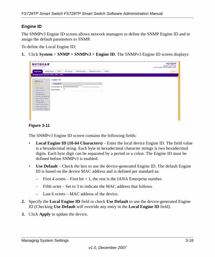
Engine IDThe SNMPv3 Engine ID screen allows network managers to define the SNMP Engine ID and to assign the default parameters to SNMP.
To define the Local Engine ID:
1. Click System > SNMP > SNMPv3 > Engine ID. The SNMPv3 Engine ID screen displays:
The SNMPv3 Engine ID screen contains the following fields:
• Local Engine ID (10-64 Characters) – Enter the local device Engine ID. The field value is a hexadecimal string. Each byte in hexadecimal character strings is two hexadecimal digits. Each byte digit can be separated by a period or a colon. The Engine ID must be defined before SNMPv3 is enabled.
• Use Default – Check the box to use the device-generated Engine ID. The default Engine ID is based on the device MAC address and is defined per standard as:
– First 4 octets – First bit = 1, the rest is the IANA Enterprise number.
– Fifth octet – Set to 3 to indicate the MAC address that follows.
– Last 6 octets – MAC address of the device.
2. Specify the Local Engine ID field or check Use Default to use the device-generated Engine ID (Checking Use Default will override any entry in the Local Engine ID field).
3. Click Apply to update the device.
Figure 3-11
Managing System Settings 3-18
v1.0, December 2007

FS728TP Smart Switch FS728TP Smart Switch Software Administration Manual
View NameThe SNMPv3 View Name screen allows the network managers to define SNMPv3 View Names. SNMPv3 views provide or block access to device features or portions of features.
To define SNMPv3 view names:
1. Click System > SNMP > SNMPv3 > View Name. The SNMPv3 View Name screen displays:
The SNMPv3 View Name screen contains the following field:
• View Name – Enter the user-defined view name. The view name can contain a maximum of 30 alphanumeric characters.
2. Select the entry.
3. Enter the View Name field in the first row.
4. Click Apply to update the device.
To add a new SNMP View Name:
1. Click System > SNMP > SNMPv3 > View Name. The SNMPv3 View Name screen displays.
2. Enter the View Name field in the first row.
3. Click Add to update the device.
To remove an SNMP View Name:
1. Click System > SNMP > SNMPv3 > View Name. The SNMPv3 View Name screen displays.
2. Select the entry to be removed.
Figure 3-12
3-19 Managing System Settings
v1.0, December 2007

FS728TP Smart Switch FS728TP Smart Switch Software Administration Manual
3. Click Delete to remove the entry.
View ContentSNMP views provide or block access to device features or portions of features. For example, a view can be defined to provide a view that SNMP group A has Read Only (R/O) access to Multicast groups, while SNMP group B has Read-Write (R/W) access to Multicast groups. Feature access is granted via the MIB name or MIB Object ID.
To define the SNMP View Content:
1. Click System > SNMP > SNMPv3 > View Content. The SNMPv3 View Content screen displays:
The SNMPv3 View Content screen contains the following fields:
Views
• View Name – Select the user-defined view name. The view name can contain a maximum of 30 alphanumeric characters.
• Object ID Subtree – Enter the device feature OID.
• View Type – Select whether the defined OID branch will be included in or excluded from the selected SNMP view. The possible field values are:
– Included – The OID is included in the SNMP view.
– Excluded – The OID is excluded from the SNMP view.
2. Select the View Name from the list in the provided field in the Views table.
Figure 3-13
Managing System Settings 3-20
v1.0, December 2007

FS728TP Smart Switch FS728TP Smart Switch Software Administration Manual
3. Enter the Object ID Subtree in the provided field in the first row.
4. Select either Included or Excluded from the View Type provided field in the first row.
5. Click Apply to update the device.
To add a new SNMP OID entry:
1. Click System > SNMP > SNMPv3 > View Content. The SNMPv3 View Content screen displays.
2. Select the View Name from the list in the provided field in the Views table.
3. Enter the Object ID Subtree in the provided field in the first row.
4. Select either Included or Excluded from the View Type provided field in the first row.
5. Click Add to update the device.
To remove an SNMP OID entry:
1. Click System > SNMP > SNMPv3 > View Content. The SNMPv3 View Content screen displays.
2. Select the View Name from the list in the provided field in the Views table.
3. Select the OID entry to be removed.
4. Click Delete to remove the entry.
Community ConfigurationAccess rights are managed by defining communities in the Community Configuration screen. When community names are changed, access rights are also changed.
3-21 Managing System Settings
v1.0, December 2007

FS728TP Smart Switch FS728TP Smart Switch Software Administration Manual
To define SNMPv3 communities:
1. Click System > SNMP > SNMPv3 > Community Configuration. The SNMPv3 Community Configuration screen displays:
The SNMPv3 Community Configuration screen contains the following fields:
• Management Station – Enter the management station IP address for which the basic SNMP community is defined.
• Community String – Enter the password used to authenticate the management station to the device.
• Group Name – Select the SNMP group from a list of SNMP groups defined in the SNMP Group Configuration screen.
2. Select the SNMP community entry.
3. Enter the Management Station and Community String in the provided fields.
4. Select the Group Name from the list.
5. Click Apply to update the device.
To add a new SNMPv3 community:
1. Click System > SNMP > SNMPv3 > Community Configuration. The SNMPv3 Community Configuration screen displays.
2. Enter the Management Station and Community String in the provided fields in the first row.
3. Select the Group Name from the list in the provided field in the first row.
4. Click Add to update the device.
Figure 3-14
Managing System Settings 3-22
v1.0, December 2007

FS728TP Smart Switch FS728TP Smart Switch Software Administration Manual
To remove an SNMPv3 community:
1. Click System > SNMP > SNMPv3 > Community Configuration. The SNMPv3 Community Configuration screen displays.
2. Select the community entry.
3. Click Delete to remove the entry.
Group ConfigurationThe SNMPv3 Groups screen provides information for creating SNMP groups and assigning SNMP access control privileges to SNMP groups. Groups allow network managers to assign access rights to specific device features or feature aspects.
To define an SNMP group:
1. Click System > SNMP > SNMPv3 > Group Configuration. The SNMPv3 Groups screen displays:
The SNMPv3 Groups screen contains the following fields:
• Group Name – Enter the user-defined group to which access control rules are applied. The field range is up to 30 characters.
• Security Model – Select the SNMP version associated with the group. The possible field values are:
– SNMPv1 – SNMPv1 is defined for the group.
– SNMPv2 – SNMPv2c is defined for the group.
– SNMPv3 – SNMPv3 is defined for the group.
Figure 3-15
3-23 Managing System Settings
v1.0, December 2007

FS728TP Smart Switch FS728TP Smart Switch Software Administration Manual
• Security Level – Select the security level attached to the group. Security levels apply to SNMPv3 only. The possible field values are:
– No Authentication – Neither the Authentication nor the Privacy security levels are assigned to the group.
– Authentication – Authenticates SNMP messages and ensures that the SNMP message’s origin is authenticated.
– Privacy – Encrypts SNMP messages.
• Operation – Select the group access rights. The possible field values are:
– Read – Management access is restricted to read-only. Changes are made to the assigned SNMP view.
– Write – Management access is read-write. Changes are made to the assigned SNMP view.
– Notify – Sends traps for the assigned SNMP view.
2. Select the SNMP group entry.
3. Select the Security Model and Security Level from the lists in the provided fields in the first row.
4. Specify the group access rights for the selected SNMP views in the Operation provided fields in the first row.
5. Click Apply to update the device.To add a new SNMPv3 group:
1. Click System > SNMP > SNMPv3 > Group Configuration. The SNMPv3 Groups screen displays.
2. Select the Security Model and Security Level from the lists in the provided fields in the first row.
3. Specify the group access rights for the selected SNMP views in the Operation provided fields in the first row.
4. Click Add to update the device.To remove an SNMPv3 group:
1. Click System > SNMP > SNMPv3 > Group Configuration. The SNMPv3 Groups screen displays.
2. Select the group entry.
Managing System Settings 3-24
v1.0, December 2007

FS728TP Smart Switch FS728TP Smart Switch Software Administration Manual
3. Click Delete to remove the entry.
User ConfigurationThe SNMPv3 User Configuration screen provides information for creating SNMP groups and assigning SNMP access control privileges to SNMP groups. Groups allow network managers to assign access rights to specific device features or feature aspects.
To define SNMP users:
1. Click System > SNMP > SNMPv3 > User Configuration. The SNMPv3 User Configuration screen displays:
The SNMPv3 User Configuration screen contains the following fields:
• User Name – Enter the user name. The field range is up to 30 alphanumeric characters.
• Group Name – Enter the group name from a list of user-defined SNMP groups. SNMP groups are defined in the Groups screen.
• Engine ID – Select either the local or remote SNMP entity to which the user is connected. Changing or removing the local SNMP Engine ID deletes the SNMPv3 user database.
• Authentication – Select the method used to authenticate users. The possible field values are:
– MD5 Key – Users are authenticated using the HMAC-MD5 algorithm.
– SHA Key – Users are authenticated using the HMAC-SHA-96 authentication level.
– MD5 Password – The HMAC-MD5-96 password is used for authentication. The user must enter a password.
Figure 3-16
3-25 Managing System Settings
v1.0, December 2007

FS728TP Smart Switch FS728TP Smart Switch Software Administration Manual
– SHA Password – Users are authenticated using the HMAC-SHA-96 authentication level. The user must enter a password.
– None – No user authentication is used.
• Password (1-32 Characters) – Enter the password for the group member.
• Authentication Key – Enter the HMAC-MD5-96 or HMAC-SHA-96 authentication level. The authentication and privacy keys are entered to define the authentication key. If only authentication is required, 16 bytes are defined. If both privacy and authentication are required, 32 bytes are defined. Each byte in hexadecimal character strings is two hexadecimal digits. Each byte can be separated by a period or a colon.
• Privacy Key – Enter the privacy key (LSB). If only authentication is required, 20 bytes are defined. If both privacy and authentication are required, 36 bytes are defined. Each byte in hexadecimal character strings is two hexadecimal digits. Each byte can be separated by a period or colon.
2. Select the user entry.
3. Enter the User Name in the provided field in the first row.
4. Select the Group Name and Engine ID from the lists in the provided fields in the first row.
5. Select the Authentication method from the list in the provided field in the first row.
6. If you selected a password method of Authentication, enter the Password in the provided field in the first row. If you selected a key method of Authentication, enter the Authentication Key and Privacy Key in the provided fields in the first row.
7. Click Apply to update the device.To add a new SNMPv3 user:
1. Click System > SNMP > SNMPv3 > Users Configuration. The SNMPv3 User Configuration screen displays.
2. Enter the User Name in the provided field in the first row.
3. Select the Group Name and Engine ID from the lists in the provided fields in the first row.
4. Select the Authentication method from the list in the provided field in the first row.
5. If you selected a password method of Authentication, enter the Password in the provided field in the first row. If you selected a key method of Authentication, enter the Authentication Key and Privacy Key in the provided fields in the first row.
6. Click Add to update the device.
Managing System Settings 3-26
v1.0, December 2007

FS728TP Smart Switch FS728TP Smart Switch Software Administration Manual
To remove an SNMPv3 user:
1. Click System > SNMP > SNMPv3 > Users Configuration. The SNMPv3 User Configuration screen displays.
2. Select the user entry.
3. Click Delete to remove the entry.
Global Trap ConfigurationThe SNMPv3 Global Trap Settings screen contains parameters for defining SNMP notification parameters.
To configure SNMP notification global parameters:
1. Click System > SNMP > SNMPv3 > Global Trap Configuration. The SNMPv3 Global Trap Settings screen displays:
The SNMPv3 Global Trap Settings screen contains the following fields:
• SNMP Notifications – Select whether or not the device can send SNMP notifications. The possible field values are:
– Enable – Enable SNMP notifications.
– Disable – Disable SNMP notifications.
• Authentication Notifications – Select the SNMP authentication failure notification status on the device. The possible field values are:
– Enable – Enable the device to send authentication failure notifications.
Figure 3-17
3-27 Managing System Settings
v1.0, December 2007

FS728TP Smart Switch FS728TP Smart Switch Software Administration Manual
– Disable – Disable the device from sending authentication failure notifications.
2. Select either Enable or Disable in the SNMP Notifications provided field.
3. Select either Enable or Disable in the Authentication Notifications provided field.
4. Click Apply to update the device.
Trap ConfigurationThe SNMPv3 Trap Configuration screen contains information for defining filters that determine whether traps are sent to specific users, and the trap type sent. SNMP notification filters provide the following services:
• Identifying Management Trap Targets
• Defining Trap Filtering
• Selecting Trap Generation Parameters
• Providing Access Control Checks
To define trap station management:
1. Click System > SNMP > SNMPv3 > Trap Configuration. The SNMPv3 Trap Configuration screen displays:
The SNMPv3 Trap Configuration screen contains the following fields:
• Recipients IP – Enter the IP address to which the traps are sent.
• Notification Type – Select the type of notification sent. The possible field values are:
Figure 3-18
Managing System Settings 3-28
v1.0, December 2007

FS728TP Smart Switch FS728TP Smart Switch Software Administration Manual
– Traps – Traps are sent.
– Informs – Informs are sent.
• User Name – Enter the user name. The field range is up to 30 alphanumeric characters.
• Security Level – Select the security level attached to the group. Security levels apply to SNMPv3 only. The possible field values are:
– No Authentication – Neither the Authentication nor the Privacy security levels are assigned to the group.
– Authentication – Authenticates SNMP messages and ensures that the SNMP message’s origin is authenticated.
– Privacy – Encrypts SNMP messages.
• UDP Port – Enter the UDP port used to send notifications. The default is 162.
• Filter Name – Select the SNMP filter name from the list of SNMP Notification filters.
• Timeout – Enter the amount of time (in seconds) the device waits before re-sending informs. The default is 15 seconds.
• Retries – Enter the amount of times the device re-sends an inform request. The default is 3 seconds.
2. Enter the Recipients IP address in the provided field in the first row.
3. Select either Traps or Informs in the Notification Type provided field in the first row.
4. Enter the User Name in the provided field in the first row.
5. Select the Security Level from the list in the provided field in the first row.
6. Enter the UDP Port in the provided field in the first row.
7. Select the Filter Name from the list in the provided field in the first row.
8. Enter the Timeout and Retries in the provided fields in the first row.
9. Click Apply to update the device.To add a new trap:
1. Click System > SNMP > SNMPv3 > Trap Configuration. The SNMPv3 Trap Configuration screen displays.
2. Enter the Recipients IP address in the provided field in the first row.
3. Select either Traps or Informs in the Notification Type provided field in the first row.
4. Enter the User Name in the provided field in the first row.
3-29 Managing System Settings
v1.0, December 2007

FS728TP Smart Switch FS728TP Smart Switch Software Administration Manual
5. Select the Security Level from the list in the provided field in the first row.
6. Enter the UDP Port in the provided field in the first row.
7. Select the Filter Name from the list in the provided field in the first row.
8. Enter the Timeout and Retries in the provided fields in the first row.
9. Click Add to update the device.To remove a trap:
1. Click System > SNMP > SNMPv3 > Trap Configuration. The SNMPv3 Trap Configuration screen displays.
2. Select the trap entry.
3. Click Delete to remove the entry.
Trap Filter NameThe SNMPv3 Trap Filter Name screen permits filtering traps based on OIDs. Each OID is linked to a device feature or a portion of a feature. The SNMPv3 Trap Filter Name screen also allows network managers to filter notifications.
To define the SNMPv3 Trap Filter Name:
1. Click System > SNMP > SNMPv3 > Trap Filter Name. The SNMPv3 Trap Filter Name screen displays:
The SNMPv3 Trap Filter Name screen contains the following field:
• Filter Name – Enter the user-defined notification filter name.
Figure 3-19
Managing System Settings 3-30
v1.0, December 2007

FS728TP Smart Switch FS728TP Smart Switch Software Administration Manual
2. Select the trap filter entry.
3. Enter the trap Filter Name in the provided field in the first row.
4. Click Apply to update the device.To add a new trap filter name:
1. Click System > SNMP > SNMPv3 > Trap Filter Name. The SNMPv3 Trap Filter Name screen displays.
2. Enter the trap Filter Name in the provided field in the first row.
3. Click Add to update the device.To remove a trap filter name:
1. Click System > SNMP > SNMPv3 > Trap Filter Name. The SNMPv3 Trap Filter Name screen displays.
2. Select the trap filter name entry.
3. Click Delete to remove the entry.
Trap Filter ContentThe SNMPv3 Trap Filter Content screen permits filtering traps based on OIDs. Each OID is linked to a device feature or a portion of a feature. The SNMPv3 Trap Filter Content screen also allows network managers to filter notifications.
To define SNMPv3 Trap Filter settings:
1. Click System > SNMP > SNMPv3 > Trap Filter Content. The SNMPv3 Trap Filter Content screen displays:
Figure 3-20
3-31 Managing System Settings
v1.0, December 2007

FS728TP Smart Switch FS728TP Smart Switch Software Administration Manual
The SNMPv3 Trap Filter Content screen contains the following fields:
Trap Filter Settings
• Filter Name – Contains a list of user-defined notification filters.
Trap Filter Settings
• Object ID Subtree – Enter the OID for which notifications are sent or blocked. If a filter is attached to an OID, traps or informs are generated and sent to the trap recipients. OIDs are selected from either the Select field or the Object ID field.
• Filter Type – Select whether to send traps or informs relating to the selected OID. The possible field values are:
– Excluded – Does not send traps or informs.
– Included – Sends traps or informs.
2. Select the Filter Name from the list in the provided field.
3. Select the trap filter content entry from the OID table.
4. Enter the Object ID Subtree in the provided field in the first row.
5. Select the Filter Type from the list in the provided field in the first row.
6. Click Apply to update the device.To add a new trap filter content entry:
1. Click System > SNMP > SNMPv3 > Trap Filter Content. The SNMPv3 Trap Filter Content screen displays.
2. Select the Filter Name from the list in the provided field.
3. Enter the Object ID Subtree in the provided field in the first row.
4. Select the Filter Type from the list in the provided field in the first row.
5. Click Add to update the device.To remove a trap filter content entry:
1. Click System > SNMP > SNMPv3 > Trap Filter Content. The SNMPv3 Trap Filter Content screen displays.
2. Select the Filter Name from the list in the provided field.
3. Select the trap filter content entry.
4. Click Delete to remove the entry.
Managing System Settings 3-32
v1.0, December 2007

FS728TP Smart Switch FS728TP Smart Switch Software Administration Manual
3-33 Managing System Settings
v1.0, December 2007

Chapter 4Configuring Switching Settings
Configuring Switching Settings
The navigation pane at the top of the web browser interface contains a Switching tab that enables you to manage your FS728TP Smart Switch with features under the following main headings:
• “Ports”
• “LAG”
• “VLAN”
• “STP”
• “Multicast”
• “Address Table”
The description that follows in this chapter describes configuring and managing switching settings in the FS728TP Smart Switch.
Ports
The Ports menu contains the following option:
• “Port Configuration”
Port ConfigurationThe Port Configuration screen contains fields for defining port parameters enabled on the ports.
4-1
v1.0, December 2007
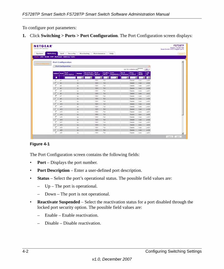
FS728TP Smart Switch FS728TP Smart Switch Software Administration Manual
To configure port parameters:
1. Click Switching > Ports > Port Configuration. The Port Configuration screen displays:
The Port Configuration screen contains the following fields:
• Port – Displays the port number.
• Port Description – Enter a user-defined port description.
• Status – Select the port’s operational status. The possible field values are:
– Up – The port is operational.
– Down – The port is not operational.
• Reactivate Suspended – Select the reactivation status for a port disabled through the locked port security option. The possible field values are:
– Enable – Enable reactivation.
– Disable – Disable reactivation.
Figure 4-1
4-2 Configuring Switching Settings
v1.0, December 2007

FS728TP Smart Switch FS728TP Smart Switch Software Administration Manual
• Port Speed – Select the data transmission rate for the port. The port type determines which speed setting options are available. Port speeds can only be configured when auto negotiation is disabled. The possible field values are:
– 10M – The port is currently operating at 10 Mbps.
– 100M – The port is currently operating at 100 Mbps.
– 1000M – The port is currently operating at 1000 Mbps.
• Duplex Mode – Select the port duplex mode. This field is configurable only when auto negotiation is disabled and the port speed is set to 10M or 100M. The possible field values are:
– Half – The interface supports transmission between the device and the client in only one direction at a time.
– Full – The interface supports transmission between the device and its link partner in both directions simultaneously.
– Auto – The interface supports transmission between the device and the link partner based on the transmission mode of the link partner.
• Auto Negotiation – Select the port auto negotiation status. Auto negotiation is a protocol between two link partners that enables a port to advertise its transmission rate, duplex mode, and flow control abilities to its partner. The possible field values are:
– Enable – Auto negotiation is enabled.
– Disable – Auto negotiation is disabled.
• Back Pressure – Select the back pressure mode of the Port. Back Pressure mode is used with half duplex mode to disable ports from receiving messages. Back Pressure mode is disabled by default. The possible field values are:
– Enable – Back pressure mode is enabled.
– Disable – Back pressure mode is disabled.
• Flow Control – Select the flow control status of the port. Operates when the port is in full duplex mode. Flow control is disabled by default. The possible field values are:
– Enable – Flow control is enabled.
– Disable – Flow control is disabled.
Configuring Switching Settings 4-3
v1.0, December 2007

FS728TP Smart Switch FS728TP Smart Switch Software Administration Manual
• MDI/MDIX – Select the MDI/MDIX status of the port. Hubs and switches are deliberately wired opposite the way end stations are wired, so that when a hub or switch is connected to an end station, a straight through Ethernet cable can be used and the pairs will match up properly. When two hubs or switches are connected to each other or two end stations are connected to each other, a crossover cable is used to ensure that the correct pairs are connected. The possible field values are:
– Auto – Provides automatic cable type detection.
– MDI (Media Dependent Interface) – Connects end stations.
– MDIX (Media Dependent Interface with Crossover) – Connects HUBs and switches.
• LAG ID – Select the LAG ID to which the selected port is assigned.
2. Select the interface.
3. Enter or modify the fields in the first row.
4. Click Apply to update the device.
LAG
A Link Aggregated Group (LAG) optimizes port usage by linking a group of ports together to form a single LAG. Aggregating ports multiplies the bandwidth between the devices, increases port flexibility, and provides link redundancy. Ports added to a LAG lose their individual port configuration. When ports are removed from the LAG, the original port configuration is applied to the ports. Ensure the following, when configuring LAGs:
• All ports within a LAG must be of the same media type.
• A VLAN is not configured on the port.
• The port is not assigned to a different LAG.
• Auto-negotiation mode is not configured on the port.
• The port is in full-duplex mode.
• All ports in the LAG have the same ingress filtering and tagged modes.
• All ports in the LAG have the same back pressure and flow control modes.
• All ports in the LAG have the same priority.
• All ports in the LAG have the same transceiver type.
• The device supports up to eight LAGs with eight ports in each LAG.
4-4 Configuring Switching Settings
v1.0, December 2007

FS728TP Smart Switch FS728TP Smart Switch Software Administration Manual
• LACP LAGs support up to 16 ports, with eight ports active at any given time.
The LAG menu contains the following options:
• “Basic”
• “Advanced”
BasicThe LAG Basic menu contains the following options:
• “LAG Configuration”
• “LAG Membership”
LAG ConfigurationThe Basic LAG Configuration screen contains fields for configuring LAG parameters. The system supports 8 LAGs, and each LAG can contain up to 8 ports.
To define LAG parameters:
1. Click Switching > LAG > Basic > LAG Configuration. The Basic LAG Configuration screen displays:
The Basic LAG Configuration screen contains the following fields:
• Interface – Displays the LAG number.
• Description – Enter a user-defined LAG description.
• Status – Select the current link operation. The possible field values are:
Figure 4-2
Configuring Switching Settings 4-5
v1.0, December 2007

FS728TP Smart Switch FS728TP Smart Switch Software Administration Manual
– Up – The LAG is currently linked and forwarding traffic.
– Down – The LAG is currently not linked.
• Reactivate Suspended – Select the action to apply to a suspended LAG. The possible field values are:
– Enable – Reactivate the suspended LAG.
– Disable – Do not reactivate the suspended LAG.
• Type – Displays the LAG type. The possible field values are:
– Static – The LAG is configured manually.
– LACP – The LAG is configured automatically.
• Speed – Select the data transmission rate for the LAG. The LAG type determines what speed setting options are available. The possible field values are:
– 10M – The LAG is currently operating at 10 Mbps.
– 100M – The LAG is currently operating at 100 Mbps.
– 1000M – The LAG is currently operating at 1000 Mbps.
• Duplex Mode – Displays the duplex mode of the LAG. The possible field value is:
– Full – The interface supports transmission between the device and its link partner in both directions simultaneously.
• Auto Negotiation – Select the auto negotiation status of the LAG. Auto Negotiation is a protocol between two link partners that enables a port to advertise its transmission rate, duplex mode, and flow control abilities to its partner. Auto Negotiation is enabled by default. The possible field values are:
– Enable – Enable auto negotiation.
– Disable – Disable auto negotiation.
• Flow Control – Select the flow control status of the LAG. Operates when the LAG is in full duplex mode. Flow Control is disabled by default. The possible field values are:
– Enable – Enable flow control.
– Disable – Disable flow control.
2. Select the interface.
3. Enter or modify the fields in the first row.
4. Click Apply to update the device.
4-6 Configuring Switching Settings
v1.0, December 2007

FS728TP Smart Switch FS728TP Smart Switch Software Administration Manual
LAG MembershipThe Basic LAG Membership screen allows network managers to assign ports to LAGs.
To assign ports to LAGs:
1. Click Switching > LAG > Basic > LAG Membership. The Basic LAG Membership screen displays:
The Basic LAG Membership screen contains the following fields:
• LAG ID – Select the LAG ID.
• LAG Name – Displays the user-defined LAG name.
• LAG Type – Select the LAG type. The possible field values are:
– Static – The LAG is configured manually.
– LACP – The LAG is configured dynamically.
• CURRENT MEMBERS – Display current members of a LAG.
2. Select the LAG ID and LAG Type.
3. Click on the gold button. The port panel displays.
4. Select the ports to be members of the LAG.
5. Click Apply to update the device.
Figure 4-3
Configuring Switching Settings 4-7
v1.0, December 2007

FS728TP Smart Switch FS728TP Smart Switch Software Administration Manual
6. Click CURRENT MEMBERS. The Current Members window opens and displays the member ports included in the LAG:
AdvancedThe LAG Advanced menu contains the following options:
• “LAG Configuration”
• “LAG Membership”
• “LACP”
• “LACP Port Priority”
LAG ConfigurationThe Advanced LAG Configuration screen contains fields for configuring LAG parameters. The system supports 8 LAGs, and each LAG can contain up to 8 ports.
Figure 4-4
4-8 Configuring Switching Settings
v1.0, December 2007

FS728TP Smart Switch FS728TP Smart Switch Software Administration Manual
To define LAG parameters:
1. Click Switching > LAG > Advanced > LAG Configuration. The Advanced LAG Configuration screen displays:
The Advanced LAG Configuration screen contains the following fields:
• Interface – Displays the LAG number.
• Description – Enter a user-defined LAG description.
• Status – Select the current link operation. The possible field values are:
– Up – The LAG is currently linked and forwarding traffic.
– Down – The LAG is currently not linked.
• Reactivate Suspended – Select the action to apply to a suspended LAG. The possible field values are:
– Enable – Reactivate the suspended LAG.
– Disable – Do not reactivate the suspended LAG.
• Type – Displays the LAG Type. The possible field values are:
– Static – The LAG is configured manually.
– LACP – The LAG is configured automatically.
• Speed – Select the data transmission rate for the LAG. The LAG type determines what speed setting options are available. LAG speeds can only be configured when auto negotiation is disabled. The possible field values are:
Figure 4-5
Configuring Switching Settings 4-9
v1.0, December 2007

FS728TP Smart Switch FS728TP Smart Switch Software Administration Manual
– 10M – The LAG is currently operating at 10 Mbps.
– 100M – The LAG is currently operating at 100 Mbps.
– 1000M – The LAG is currently operating at 1000 Mbps.
• Duplex Mode – Displays the duplex mode of the LAG. The possible field value is:
– Full – The interface supports transmission between the device and its link partner in both directions simultaneously.
• Auto Negotiation – Select the auto negotiation status of the LAG. Auto Negotiation is a protocol between two link partners that enables a port to advertise its transmission rate, duplex mode, and flow control abilities to its partner. Auto Negotiation is enabled by default. The possible field values are:
– Enable – Enable auto negotiation.
– Disable – Disable auto negotiation.
• Flow Control – Select the flow control status of the LAG. Operates when the port is in full duplex mode. Flow Control is disabled by default. The possible field values are:
– Enable – Enable flow control.
– Disable – Disable flow control.
2. Select the interface.
3. Enter or modify the fields in the first row.
4. Click Apply to update the device.
4-10 Configuring Switching Settings
v1.0, December 2007

FS728TP Smart Switch FS728TP Smart Switch Software Administration Manual
LAG MembershipThe Advanced LAG Membership screen allows network managers to assign ports to LAGs.
To assign ports to LAGs:
1. Click Switching > LAG > Advanced > LAG Membership. The LAG Membership screen displays:
The Advanced LAG Membership screen contains the following fields:
• LAG ID – Select the LAG ID.
• LAG Name – Displays the user-defined LAG name.
• LAG Type – Select the LAG type. The possible field values are:
– Static – The LAG is configured manually.
– LACP – The LAG is configured automatically.
• CURRENT MEMBERS – Display current members of a LAG.
2. Select the LAG ID and LAG Type.
3. Click on the gold button. The port panel displays.
4. Select the ports to be members of the LAG.
5. Click Apply to update the device.
Figure 4-6
Configuring Switching Settings 4-11
v1.0, December 2007

FS728TP Smart Switch FS728TP Smart Switch Software Administration Manual
6. Click CURRENT MEMBERS. The Current Members window opens and displays the member ports included in the LAG:
LACPAggregated links can be set up manually or automatically established by enabling LACP on the relevant links. Aggregated ports can be linked into link-aggregation port-groups. Each group is comprised of ports with the same speed. The LACP screen contains fields for configuring LACP.
To configure LACP:
1. Click Switching > LAG > Advanced > LACP Configuration. The LACP Configuration screen displays:
The LACP Configuration screen contains the following field:
• LACP System Priority – Enter the system priority value. The field range is 1-65535. The field default is 1.
2. Enter the LACP System Priority in the provided field.
3. Click Apply to update the device.
Figure 4-7
Figure 4-8
4-12 Configuring Switching Settings
v1.0, December 2007

FS728TP Smart Switch FS728TP Smart Switch Software Administration Manual
LACP Port PriorityTo configure LACP port priority:
1. Click Switching > LAG > Advanced > LACP Port Configuration. The LACP Port Priority screen displays
The LACP Port Priority screen contains the following fields:
• Interface – Displays the interface number to which timeout and priority values are assigned.
• LACP Priority – Enter the port priority value. The field range is 1-65535.
• Timeout – Select the administrative LACP timeout. The possible field values are:
– Long – A long timeout value (90 seconds). This is the default.
– Short – A short timeout value (3 seconds).2. Select the interface.3. Enter the LACP Priority and select the Timeout in the provided fields in the first row.4. Click Apply to update the device.
Figure 4-9
Configuring Switching Settings 4-13
v1.0, December 2007

FS728TP Smart Switch FS728TP Smart Switch Software Administration Manual
VLAN
VLANs are logical subgroups with a Local Area Network (LAN) which combine user stations and network devices into a single unit, regardless of the physical LAN segment to which they are attached. VLANs allow network traffic to flow more efficiently within subgroups. VLANs use software to reduce the amount of time it takes for network changes, additions, and moves to be implemented.
VLANs have no minimum number of ports, and can be created per unit, per device, or through any other logical connection combination, since they are software-based and not defined by physical attributes.
VLANs function at Layer 2. Since VLANs isolate traffic within the LAN, a Layer 3 router working at a protocol level is required to allow traffic flow between VLANs. Layer 3 routers identify segments and coordinate with VLANs. VLANs are Broadcast and Multicast domains. Broadcast and Multicast traffic is transmitted only in the VLAN in which the traffic is generated.
VLAN tagging provides a method of transferring VLAN information between VLAN groups. VLAN tagging attaches a 4-byte tag to packet headers. The VLAN tag indicates to which VLAN the packets belong. VLAN tags are attached to the VLAN by either the end station or the network device. VLAN tags also contain VLAN network priority information.
The VLAN menu contains the following options:
• “Basic”
• “Advanced”
BasicThe VLAN Basic menu contains the following options:
• “VLAN Configuration”
VLAN ConfigurationThe Basic VLAN Configuration screen provides information and global parameters for configuring and working with VLANs. The maximum number of VLANs is 128.
4-14 Configuring Switching Settings
v1.0, December 2007

FS728TP Smart Switch FS728TP Smart Switch Software Administration Manual
To define VLAN properties:
1. Click Switching > VLAN > Basic > VLAN Configuration. The Basic VLAN Configuration screen displays:
The Basic VLAN Configuration screen contains the following fields:
• VLAN ID – Enter the VLAN ID. The field range is 1-4093.
• VLAN Name – Enter the user-defined VLAN name.
• Type – Displays the VLAN type. The possible field values are:
– Static – The VLAN is user-defined.
– Default – The default VLAN ID is 1. It cannot be modified by the user.
2. Select the VLAN entry.
3. Enter the VLAN ID and VLAN Name in the provided fields in the first row.
4. Click Apply to update the device.
To add a new VLAN:
1. Click Switching > VLAN > Basic > VLAN Configuration. The Basic VLAN Configuration screen displays.
2. Enter the VLAN ID and VLAN Name in the provided fields in the first row.
3. Click Add to update the device.
To remove a VLAN:
1. Click Switching > VLAN > Basic > VLAN Configuration. The Basic VLAN Configuration screen displays.
Figure 4-10
Configuring Switching Settings 4-15
v1.0, December 2007
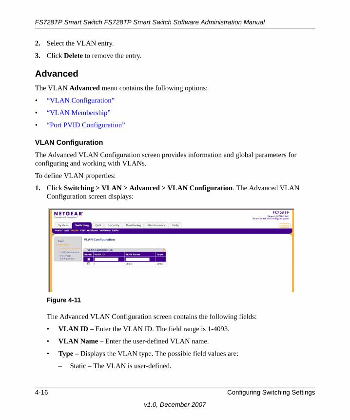
FS728TP Smart Switch FS728TP Smart Switch Software Administration Manual
2. Select the VLAN entry.
3. Click Delete to remove the entry.
AdvancedThe VLAN Advanced menu contains the following options:
• “VLAN Configuration”
• “VLAN Membership”
• “Port PVID Configuration”
VLAN ConfigurationThe Advanced VLAN Configuration screen provides information and global parameters for configuring and working with VLANs.
To define VLAN properties:
1. Click Switching > VLAN > Advanced > VLAN Configuration. The Advanced VLAN Configuration screen displays:
The Advanced VLAN Configuration screen contains the following fields:
• VLAN ID – Enter the VLAN ID. The field range is 1-4093.
• VLAN Name – Enter the user-defined VLAN name.
• Type – Displays the VLAN type. The possible field values are:
– Static – The VLAN is user-defined.
Figure 4-11
4-16 Configuring Switching Settings
v1.0, December 2007

FS728TP Smart Switch FS728TP Smart Switch Software Administration Manual
– Default – The VLAN is the default VLAN. The default VLAN is enabled by default.
2. Select the VLAN entry.
3. Enter the VLAN ID and VLAN Name in the provided fields in the first row.
4. Click Apply to update the device.
To add a new VLAN:
1. Click Switching > VLAN > Advanced > VLAN Configuration. The Advanced VLAN Configuration screen displays.
2. Enter the VLAN ID and VLAN Name in the provided fields in the first row.
3. Click AddApply to update the device.
To remove a VLAN:
1. Click Switching > VLAN > Advanced > VLAN Configuration. The Advanced VLAN Configuration screen displays.
2. Select the VLAN entry.
3. Click Delete to remove the entry.
VLAN MembershipThe VLAN Membership screen contains a table that maps ports to VLANs. Ports are assigned VLAN membership by toggling through the Port Control settings.
Configuring Switching Settings 4-17
v1.0, December 2007

FS728TP Smart Switch FS728TP Smart Switch Software Administration Manual
To define VLAN group membership:
1. Click Switching > VLAN > Advanced > VLAN Membership. The VLAN Membership screen displays:
The VLAN Membership screen contains the following fields:
• VLAN ID – Select the VLAN ID to be displayed and configured. VLAN ID = 1 cannot be modified.
• VLAN Name – Displays the name of the VLAN.
• VLAN Type – Displays the VLAN type. The possible field values are:
– Static – The VLAN is user-defined.
– Default – The VLAN is the default VLAN. The default VLAN is enabled.
• Group Operation – Select the VLAN membership for all ports and LAGs. The possible field values are:
– Tag All – Defines all selected interfaces as tagged VLAN members. Packets belonging to the respective VLAN are tagged. The packets contain VLAN information.
– Untag All – Defines all selected interfaces as untagged VLAN members. Packets belonging to the respective VLAN are untagged.
– Remove All – Remove all the interfaces participating in the VLAN.
2. Select the VLAN ID from the list in the provided field.
Figure 4-12
4-18 Configuring Switching Settings
v1.0, December 2007

FS728TP Smart Switch FS728TP Smart Switch Software Administration Manual
3. Select the Group Operation from the list in the provided field.
4. Click Apply to update the device.
To tag or untag selected ports or LAGs:
1. Click Switching > VLAN > Advanced > VLAN Membership. The VLAN Membership screen displays.
2. Click a gold button to display the ports or LAGs.
3. Click the boxes below the selected ports or LAGs to mark them as tagged (T) or untagged (U).
4. Click Apply to update the device.
To tag or untag all the ports or all the LAGs:
1. Click Switching > VLAN > Advanced > VLAN Membership. The VLAN Membership screen displays.
2. Click the ports quick box or the LAG quick box, repeatedly if necessary, until a T or U appears in the quick box, marking all the ports or LAGs as tagged or untagged, respectively.
3. Click Apply to update the device.
To view VLAN tagged port members:
1. Click Switching > VLAN > Advanced > VLAN Membership. The VLAN Membership screen displays.
2. Click TAGGED PORT MEMBERS. The VLAN Tagged Ports window opens:
Figure 4-13
Configuring Switching Settings 4-19
v1.0, December 2007

FS728TP Smart Switch FS728TP Smart Switch Software Administration Manual
To view VLAN untagged port members:
1. Click Switching > VLAN > Advanced > VLAN Membership. The VLAN Membership screen displays.
2. Click UNTAGGED PORT MEMBERS. The VLAN Untagged Ports screen opens:
Port PVID ConfigurationThe Port PVID Configuration screen contains parameters for assigning Port VLAN ID (PVID) values to interfaces. All ports must have a defined PVID. If no other value is configured the default VLAN PVID is used. VLAN ID 1 belongs to the default VLAN which cannot be deleted from the system. Once the PVID is changed from 1 to another VLAN ID on an interface, the default VLAN on that interface is automatically removed.
Figure 4-14
4-20 Configuring Switching Settings
v1.0, December 2007

FS728TP Smart Switch FS728TP Smart Switch Software Administration Manual
To configure Port PVID parameters:
1. Click Switching > VLAN > Advanced > Port PVID Configuration. The Port PVID Configuration screen displays:
The Port PVID Configuration screen contains the following fields:
• Interface – Displays the interface id (port number or LAG number) to which the PVID tag is assigned.
• PVID – Enter the PVID value. The possible field range is 1-4093.
2. Select an interface.
3. Enter the PVID in the provided field in the first row.
4. Click Apply to update the device.
Figure 4-15
Configuring Switching Settings 4-21
v1.0, December 2007

FS728TP Smart Switch FS728TP Smart Switch Software Administration Manual
STP
Spanning Tree Protocol (STP) provides tree topography for any arrangement of bridges. STP also provides a single path between end stations on a network, eliminating loops. Loops occur when alternate routes exist between hosts. Loops in an extended network can cause bridges to forward traffic indefinitely, resulting in increased traffic and reducing network efficiency.
The STP menu contains the following options:
• “Basic”
• “Advanced”
BasicThe STP Basic menu contains the following options:
• “STP Configuration”
STP ConfigurationThe Basic STP Configuration screen contains parameters for enabling STP on the device.
To configure STP on the device:
1. Click Switching > STP > Basic > STP Configuration. The Basic STP Configuration screen displays:
The Basic STP Configuration screen contains the following fields:
Figure 4-16
4-22 Configuring Switching Settings
v1.0, December 2007

FS728TP Smart Switch FS728TP Smart Switch Software Administration Manual
Global Settings
• Spanning Tree State – Select the STP state on the device. The possible field values are:
– Enable – Enable STP on the device.
– Disable – Disable STP on the device.
Status
• Bridge Identifier – Displays the Bridge priority and MAC address.
• Time Since Topology Change – Displays the amount of time that has elapsed since the bridge was initialized or reset or the last topology change that occurred. The time is displayed in a day-hour-minute-second format, such as 2 days 5 hours 10 minutes and 4 seconds. The current root port and current root path cost display as zero when the device is not connected to the network.
• Designated Root – Displays the Root Bridge priority and MAC address.
• Root Port – Displays the port number that offers the lowest cost path from this bridge to the Root Bridge. This field is significant when the bridge is not the Root Bridge.
• Max Age (Sec) – Displays the device Maximum Age Time. The Maximum Age Time is the amount of time in seconds a bridge waits before sending configuration messages. The default Maximum Age Time is 20 seconds.
• Forward Delay (Sec) – Displays the device Forward Delay Time. The Forward Delay Time is the amount of time in seconds a bridge remains in a listening and learning state before forwarding packets. The default is 15 seconds.
• Hello Time (Sec) – Displays the device Hello Time. The Hello Time indicates the amount of time in seconds a Root Bridge waits between configuration messages. The default is 2 seconds.
2. Select Enable or Disable in the Spanning Tree State provided field.
3. Click Apply to update the device.
AdvancedThe STP Advanced menu contains the following options:
• “STP Configuration”
• “CST Configuration”
• “CST Port Configuration”
Configuring Switching Settings 4-23
v1.0, December 2007

FS728TP Smart Switch FS728TP Smart Switch Software Administration Manual
STP ConfigurationThe Advanced STP Configuration screen contains parameters for enabling STP on the device.
To configure STP on the device:
1. Click Switching > STP > Advanced > STP Configuration. The Advanced STP Configuration screen displays:
The Advanced STP Configuration screen contains the following fields:
Global Settings
• Spanning Tree State – Select the STP state on the device. The possible field values are:
– Enable – Enable STP on the device.
– Disable – Disable STP on the device.
Status
• Bridge Identifier – Displays the Bridge priority and MAC address.
• Time Since Topology Change – Displays the amount of time that has elapsed since the bridge was initialized or reset, and the last topographic change that occurred. The time is displayed in a day-hour-minute-second format, such as 2 days 5 hours 10 minutes and 4 seconds. The current root port and current root cost display as zero when the device is not connected to the network.
• Designated Root – Displays the Root Bridge priority and MAC address.
Figure 4-17
4-24 Configuring Switching Settings
v1.0, December 2007

FS728TP Smart Switch FS728TP Smart Switch Software Administration Manual
• Root Port – Indicates the port number that offers the lowest cost path from this bridge to the Root Bridge. This field is significant when the bridge is not the Root Bridge. The default is zero.
• Max Age (Sec) – Displays the device Maximum Age Time. The Maximum Age Time is the amount of time in seconds a bridge waits before sending configuration messages. The default Maximum Age Time is 20 seconds.
• Forward Delay (Sec) – Displays the device Forward Delay Time. The Forward Delay Time is the amount of time in seconds a bridge remains in a listening and learning state before forwarding packets. The default is 15 seconds.
• Hello Time (Sec) – Displays the device Hello Time. The Hello Time indicates the amount of time in seconds. The device waits between configuration messages. The default is 2 seconds.
2. Select Enable or Disable in the Spanning Tree State provided field.
3. Click Apply to update the device.
CST ConfigurationThe Common Spanning Tree (CST) describes the topology connecting STP/RSTP Bridges and MSTP regions.
To configure CST on the device:
1. Click Switching > STP > Advanced > CST Configuration. The CST Configuration screen displays:
Figure 4-18
Configuring Switching Settings 4-25
v1.0, December 2007

FS728TP Smart Switch FS728TP Smart Switch Software Administration Manual
The CST Configuration screen contains the following fields:
CST Configuration
• Bridge Priority – Enter the bridge priority value. When switches or bridges are running STP, each is assigned a priority. After exchanging BPDUs, the device with the lowest priority value becomes the Root Bridge. The default value is 32768. The bridge priority value is provided in increments of 4096.
• Hello Time – Enter the device Hello Time. The Hello Time indicates the amount of time in seconds a Root Bridge waits between configuration messages. The default is 2 seconds.
• Max Age – Enter the device Maximum Age Time. The Maximum Age Time is the amount of time in seconds a bridge waits before sending configuration messages. The default Maximum Age Time is 20 seconds.
• Forward Delay – Enter the device Forward Delay Time. The Forward Delay Time is the amount of time in seconds a bridge remains in a listening and learning state before forwarding packets. The default is 15 seconds.
Designated Root
• Root Bridge ID – Displays the priority and MAC Address of the root bridge.
• Root Port – Displays the port number that offers the lowest cost path from this bridge to the Root Bridge. This field is significant when the bridge is not the Root Bridge.
• Root Path Cost – Displays the cost of the path from this bridge to the Root Bridge.
2. Enter the Bridge Priority in the provided field.
3. Select Hello Time, Max Age or Forward Delay and enter the value in the provided field.
4. Click Apply to update the device.
4-26 Configuring Switching Settings
v1.0, December 2007
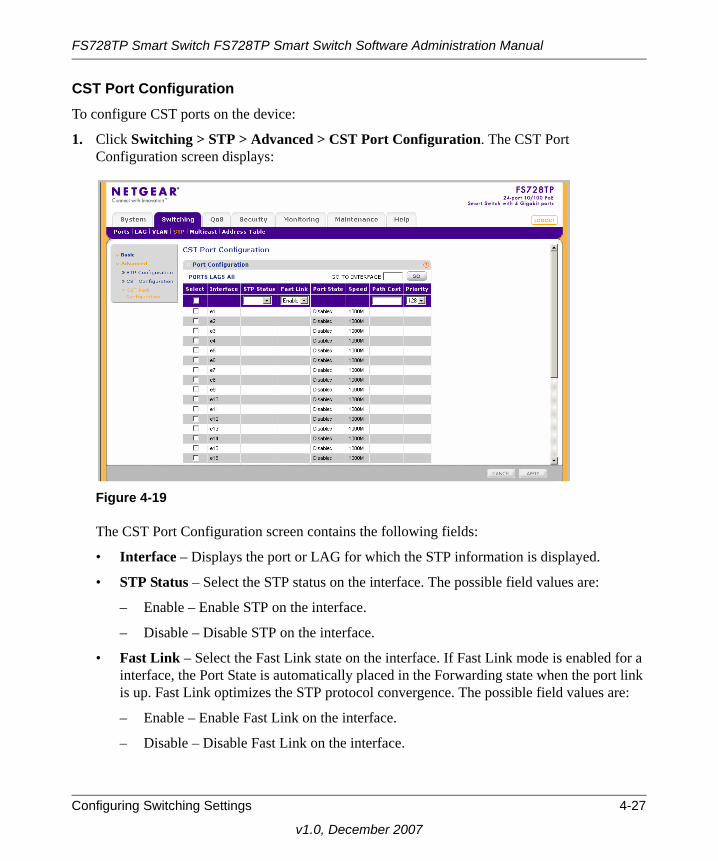
FS728TP Smart Switch FS728TP Smart Switch Software Administration Manual
CST Port ConfigurationTo configure CST ports on the device:
1. Click Switching > STP > Advanced > CST Port Configuration. The CST Port Configuration screen displays:
The CST Port Configuration screen contains the following fields:
• Interface – Displays the port or LAG for which the STP information is displayed.
• STP Status – Select the STP status on the interface. The possible field values are:
– Enable – Enable STP on the interface.
– Disable – Disable STP on the interface.
• Fast Link – Select the Fast Link state on the interface. If Fast Link mode is enabled for a interface, the Port State is automatically placed in the Forwarding state when the port link is up. Fast Link optimizes the STP protocol convergence. The possible field values are:
– Enable – Enable Fast Link on the interface.
– Disable – Disable Fast Link on the interface.
Figure 4-19
Configuring Switching Settings 4-27
v1.0, December 2007

FS728TP Smart Switch FS728TP Smart Switch Software Administration Manual
• Port State – Displays the current STP state of a port. If enabled, the port state determines what forwarding action is taken on traffic. Possible port states are:
– Forwarding – STP is enabled on the port, and the port is forwarding packets based on the STP topology.
– Disabled – STP is currently disabled on the port. The port forwards traffic while learning MAC addresses.
– Blocking – The port is currently blocked and cannot forward traffic or learn MAC addresses. Blocking is displayed when STP is enabled.
– Listening – The port is in Listening mode. The port cannot forward traffic nor can it learn MAC addresses.
– Learning – The port is in Learning mode. The port cannot forward traffic, however it can learn new MAC addresses.
• Speed – Displays the speed at which the port is operating.
• Path Cost – Enter the method used to assign default path cost to STP ports. The possible field range is 1 - 200000000. The default path cost assigned to an interface varies according to the selected method.
• Priority – Enter the port priority value. When switches or ports are running STP, each is assigned a priority. After exchanging BPDUs, the device with the lowest priority value becomes the Root Port. The default value is 32768. The port priority value is provided in increments of 4096.
2. Select the STP Status and Fast Link status in the provided fields.
3. Enter the Path Cost and Priority in the provided fields.
4. Click Apply to update the device.
Multicast
Multicast forwarding allows a single packet to be forwarded to multiple destinations. L2 Multicast service is based on L2 switch receiving a single packet addressed to a specific Multicast address. Multicast forwarding creates copies of the packet, and transmits the packets to the relevant ports.
• Registered Multicast traffic – If traffic addressed to a registered Multicast group is seen it is handled by an entry in the Multicast Filtering Database and forwarded only to the registered ports.
4-28 Configuring Switching Settings
v1.0, December 2007

FS728TP Smart Switch FS728TP Smart Switch Software Administration Manual
• Unregistered Multicast traffic – If traffic addressed to an unregistered Multicast group is seen it is handled by a special entry in the Multicast Filtering Database. The default setting of this is to flood all such traffic (traffic in unregistered Multicast groups).
Layer 2 switching forwards Multicast packets to all relevant VLAN ports by default, treating the packet as a Multicast transmission. Multicast traffic forwarding is functional. However, irrelevant ports also receive the Multicast, causing increased network traffic. Multicast forwarding filters enable forwarding of Layer 2 packets to port subsets, defined in the Multicast filter database.
The device supports forwarding L2 Multicast Packets. Multicast forwarding is enabled by default, and not configurable by user.
The Multicast menu contains the following options:
• “Basic”
• “Advanced”
BasicThe Multicast Basic menu contains the following options:
• “IGMP Snooping Configuration”
IGMP Snooping ConfigurationWhen IGMP snooping is enabled, all IGMP packets are forwarded to the CPU. The CPU analyzes the incoming packets and determines which ports want to join which Multicast groups, which ports have Multicast routers generating IGMP queries, and what routing protocols are forwarding packets and Multicast traffic. Ports requesting to join a specific Multicast group issues an IGMP report specifying that Multicast group. This results in the creation of the Multicast filtering database.
Configuring Switching Settings 4-29
v1.0, December 2007
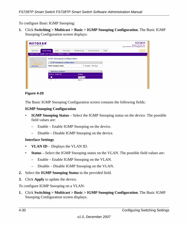
FS728TP Smart Switch FS728TP Smart Switch Software Administration Manual
To configure Basic IGMP Snooping:
1. Click Switching > Multicast > Basic > IGMP Snooping Configuration. The Basic IGMP Snooping Configuration screen displays:
The Basic IGMP Snooping Configuration screen contains the following fields:
IGMP Snooping Configuration
• IGMP Snooping Status – Select the IGMP Snooping status on the device. The possible field values are:
– Enable – Enable IGMP Snooping on the device.
– Disable – Disable IGMP Snooping on the device.
Interface Settings
• VLAN ID – Displays the VLAN ID.
• Status – Select the IGMP Snooping status on the VLAN. The possible field values are:
– Enable – Enable IGMP Snooping on the VLAN.
– Disable – Disable IGMP Snooping on the VLAN.
2. Select the IGMP Snooping Status in the provided field.
3. Click Apply to update the device.
To configure IGMP Snooping on a VLAN:
1. Click Switching > Multicast > Basic > IGMP Snooping Configuration. The Basic IGMP Snooping Configuration screen displays.
Figure 4-20
4-30 Configuring Switching Settings
v1.0, December 2007
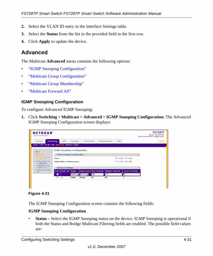
FS728TP Smart Switch FS728TP Smart Switch Software Administration Manual
2. Select the VLAN ID entry in the Interface Settings table.
3. Select the Status from the list in the provided field in the first row.
4. Click Apply to update the device.
AdvancedThe Multicast Advanced menu contains the following options:
• “IGMP Snooping Configuration”
• “Multicast Group Configuration”
• “Multicast Group Membership”
• “Multicast Forward All”
IGMP Snooping ConfigurationTo configure Advanced IGMP Snooping:
1. Click Switching > Multicast > Advanced > IGMP Snooping Configuration. The Advanced IGMP Snooping Configuration screen displays:
The IGMP Snooping Configuration screen contains the following fields:
IGMP Snooping Configuration
• Status – Select the IGMP Snooping status on the device. IGMP Snooping is operational if both the Status and Bridge Multicast Filtering fields are enabled. The possible field values are:
Figure 4-21
Configuring Switching Settings 4-31
v1.0, December 2007

FS728TP Smart Switch FS728TP Smart Switch Software Administration Manual
– Enable – Enable IGMP Snooping on the device.
– Disable – Disable IGMP Snooping on the device.
• Bridge Multicast Filtering Status – Select the bridge Multicast filtering status on the device. The possible field values are:
– Enable – Enable Multicast filtering on the device.
– Disable – Disable Multicast filtering on the device. If Multicast filtering is disabled, Multicast frames are flooded to all ports in the relevant VLAN. Disabled is the default value.
Interface Settings
• VLAN ID – Displays the VLAN ID.
• Status – Select the IGMP Snooping status on the VLAN. The possible field values are:
– Enable – Enable IGMP Snooping on the VLAN.
– Disable – Disable IGMP Snooping on the VLAN.
• Auto Learn – Select the Auto Learn status on the device. If Auto Learn is enabled, the devices automatically learns where other Multicast groups are located. The possible field values are:
– Enable – Enable auto learn.
– Disable – Disable auto learn.
• Host Timeout – Enter the amount of time host waits to receive a message before timing out. The default time is 260 seconds.
• MRouter Timeout – Enter the amount of the time the Multicast router waits to receive a message before it times out. The default value is 300 seconds.
• Leave Timeout – Enter the amount of time the host waits, after requesting to leave the IGMP group and not receiving a Join message from another station, before timing out. If a Leave Timeout occurs, the switch notifies the Multicast device to stop sending traffic The Leave Timeout value is either user-defined, or an immediate leave value. The default timeout is 10 seconds.
2. Select the IGMP Snooping Status and Bridge Multicast Filtering Status in the provided fields.
3. Click Apply to update the device.
4-32 Configuring Switching Settings
v1.0, December 2007

FS728TP Smart Switch FS728TP Smart Switch Software Administration Manual
To configure IGMP Snooping on a VLAN:
1. Click Switching > Multicast > Advanced > IGMP Snooping Configuration. The Advanced IGMP Snooping Configuration screen displays.
2. Select the VLAN ID entry in the Interface Settings table.
3. Select the Status and Auto Learn status from the lists in the provided fields in the first row.
4. Enter the Host, MRouter and Leave Timeouts in the provided fields in the first row.
5. Click Apply to update the device.
Multicast Group ConfigurationThe Multicast Group Configuration screen allows you to create, delete and modify Multicast service groups. The Multicast Group Configuration table can contain up to 32 Multicast service groups.
To configure Multicast groups:
1. Click Switching > Multicast > Advanced > Multicast Group Configuration. The Multicast Group Configuration screen displays:
The Multicast Group Configuration screen contains the following information:
• VLAN ID – Displays the VLAN ID.
• VLAN Name – Displays the user-defined VLAN name.
• Multicast Address – Enter the Multicast group MAC Address associated with the VLAN.
Figure 4-22
Configuring Switching Settings 4-33
v1.0, December 2007

FS728TP Smart Switch FS728TP Smart Switch Software Administration Manual
• Type – Indicates the VLAN ID status in relation to the Multicast group.
– Static – Attaches the VLAN ID to the Multicast group as static member.
– Dynamic – Dynamically joins the VLAN ID to the Multicast group.
2. Select the group entry.
3. Enter the Multicast Address in the provided field in the first row.
4. Click Apply to update the device.
Multicast Group MembershipThe Multicast Group Membership screen displays the ports and LAGs attached to the selected VLAN and the Multicast service group. The Port and LAG tables also reflect the manner in which the port or LAGs joined the Multicast group.
To configure Multicast group membership:
1. Click Switching > Multicast > Advanced > Multicast Group Membership. The Multicast Group Membership screen displays:
The Multicast Group Membership screen contains the following information:
Figure 4-23
4-34 Configuring Switching Settings
v1.0, December 2007

FS728TP Smart Switch FS728TP Smart Switch Software Administration Manual
Multicast Group Membership
• VLAN ID – Enter the VLAN ID.
• VLAN Name – Displays the user defined VLAN name.
• Multicast Address – Enter the Multicast group MAC address.
Multicast Group
• Interface – Displays the ports and LAGs for which the Multicast settings are displayed.
• Interface Status – Select the interface status. The possible field values are:
– Static – The interface is joined to the Multicast group statically.
– Forbidden – The interface is forbidden to join the Multicast group.
– Excluded – The interface is not included in the Multicast group.
2. Select the VLAN ID from the list in the provided field.
3. Select the Multicast Address from the list in the provided field.
4. Select the interface entry in the Multicast Group table.
5. Select the Interface Status from the list in the provided field in the first row.
6. Click Apply to update the device.
Multicast Forward AllThe Multicast Forward All screen contains fields for attaching ports or LAGs to a device that is attached to a neighboring Multicast router/switch. Once IGMP Snooping is enabled, Multicast packets are forwarded only to the appropriate port or VLAN.
Configuring Switching Settings 4-35
v1.0, December 2007

FS728TP Smart Switch FS728TP Smart Switch Software Administration Manual
To define Multicast forward all settings:
1. Click Switching > Multicast > Advanced > Multicast Forward All. The Multicast Forward All screen displays:
The Multicast Forward All screen contains the following information:
Multicast Forward All
• VLAN ID – Enter the VLAN ID.
• VLAN Name – Displays the user defined VLAN name.
Multicast Forward All
• Interface – Displays the interface for which the Multicast settings are displayed.
• Interface Status – Select the interface status. The possible field values are:
– Static – The interface is added to the Multicast forward group statically.
– Forbidden – The interface is forbidden to join the mulitcast group.
– Excluded – The interface is not included in the Multicast group.
2. Select the VLAN ID from the list in the provided fields.
Figure 4-24
4-36 Configuring Switching Settings
v1.0, December 2007

FS728TP Smart Switch FS728TP Smart Switch Software Administration Manual
3. Select the port or LAG interface entry in the Multicast Group table.
4. Select the Interface Status from the list in the provided field in the first row.
5. Click Apply to update the device.
Address Table
Packets addressed to destinations stored in either the Static or Dynamic databases are immediately forwarded to the port. The Dynamic MAC Address Table can be sorted by interface, VLAN, or MAC Address. MAC addresses are dynamically learned from packets from sources that arrive at the device as apposed to Static addresses that are configured manually.
An address becomes associated with a port by learning the port from the frame’s source address but if a frame that is addressed to a destination MAC address is not associated with a port, that frame is flooded to all relevant VLAN ports. To prevent the bridging table from overflowing, a dynamic MAC address, from which no traffic arrives for a set period, is erased.
The Address Table menu contains the following options:
• “Basic”
• “Advanced”
BasicThe Address Table Basic menu contains the following options:
• “Address Table”
Address TableThe Basic Address Table screen displays the MAC Address table according to the defined categories.
Configuring Switching Settings 4-37
v1.0, December 2007
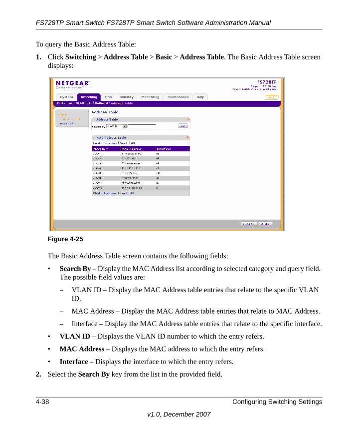
FS728TP Smart Switch FS728TP Smart Switch Software Administration Manual
To query the Basic Address Table:
1. Click Switching > Address Table > Basic > Address Table. The Basic Address Table screen displays:
The Basic Address Table screen contains the following fields:
• Search By – Display the MAC Address list according to selected category and query field. The possible field values are:
– VLAN ID – Display the MAC Address table entries that relate to the specific VLAN ID.
– MAC Address – Display the MAC Address table entries that relate to MAC Address.
– Interface – Display the MAC Address table entries that relate to the specific interface.
• VLAN ID – Displays the VLAN ID number to which the entry refers.
• MAC Address – Displays the MAC address to which the entry refers.
• Interface – Displays the interface to which the entry refers.
2. Select the Search By key from the list in the provided field.
Figure 4-25
4-38 Configuring Switching Settings
v1.0, December 2007
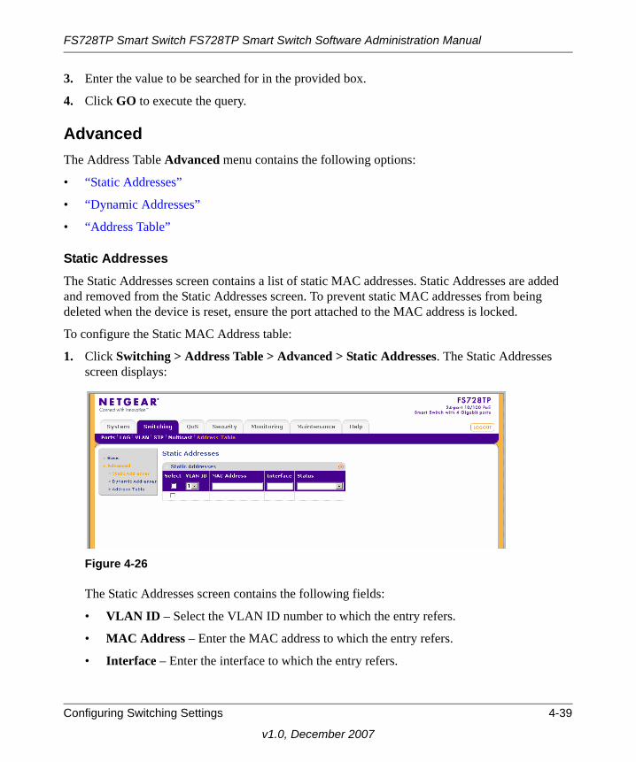
FS728TP Smart Switch FS728TP Smart Switch Software Administration Manual
3. Enter the value to be searched for in the provided box.
4. Click GO to execute the query.
AdvancedThe Address Table Advanced menu contains the following options:
• “Static Addresses”
• “Dynamic Addresses”
• “Address Table”
Static AddressesThe Static Addresses screen contains a list of static MAC addresses. Static Addresses are added and removed from the Static Addresses screen. To prevent static MAC addresses from being deleted when the device is reset, ensure the port attached to the MAC address is locked.
To configure the Static MAC Address table:
1. Click Switching > Address Table > Advanced > Static Addresses. The Static Addresses screen displays:
The Static Addresses screen contains the following fields:
• VLAN ID – Select the VLAN ID number to which the entry refers.
• MAC Address – Enter the MAC address to which the entry refers.
• Interface – Enter the interface to which the entry refers.
Figure 4-26
Configuring Switching Settings 4-39
v1.0, December 2007
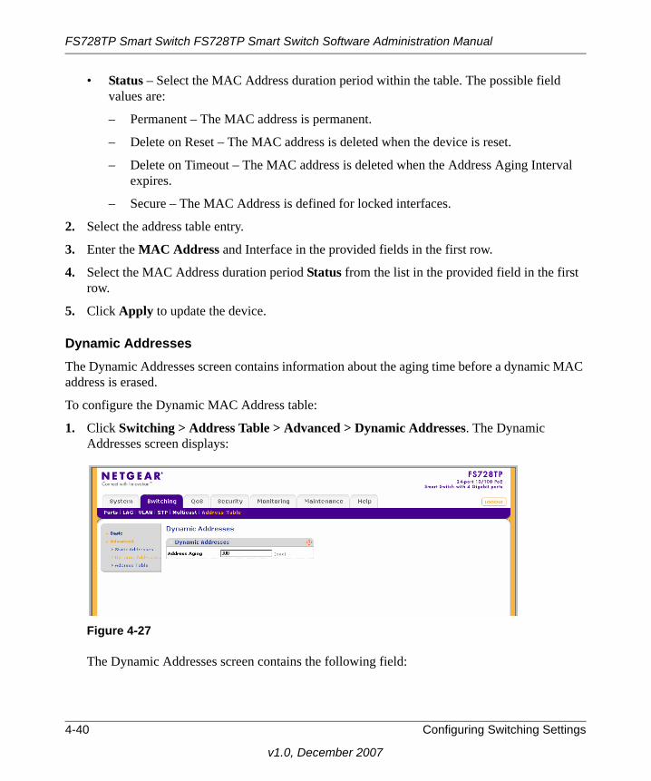
FS728TP Smart Switch FS728TP Smart Switch Software Administration Manual
• Status – Select the MAC Address duration period within the table. The possible field values are:
– Permanent – The MAC address is permanent.
– Delete on Reset – The MAC address is deleted when the device is reset.
– Delete on Timeout – The MAC address is deleted when the Address Aging Interval expires.
– Secure – The MAC Address is defined for locked interfaces.
2. Select the address table entry.
3. Enter the MAC Address and Interface in the provided fields in the first row.
4. Select the MAC Address duration period Status from the list in the provided field in the first row.
5. Click Apply to update the device.
Dynamic AddressesThe Dynamic Addresses screen contains information about the aging time before a dynamic MAC address is erased.
To configure the Dynamic MAC Address table:
1. Click Switching > Address Table > Advanced > Dynamic Addresses. The Dynamic Addresses screen displays:
The Dynamic Addresses screen contains the following field:
Figure 4-27
4-40 Configuring Switching Settings
v1.0, December 2007

FS728TP Smart Switch FS728TP Smart Switch Software Administration Manual
• Address Aging – Enter the amount of time the MAC address remains in the Dynamic MAC Address table before it is timed out if no traffic from the source is detected. The range is 10 – 630 seconds. The default value is 300 seconds.
2. Enter the Address Aging in the provided field in the first row.
3. Click Apply to update the device.
Address TableThe Advanced Address Table screen displays the MAC Address table according to the defined categories.
To query the Advanced MAC Address Table:
1. Click Switching > Address Table > Advanced > Address Table. The Advanced Address Table screen displays:
The Advanced Address Table screen contains the following fields:
• Search By – Display the MAC Address which can be sorted according to VLAN ID, MAC Address or Interface. The possible field values are:
Figure 4-28
Configuring Switching Settings 4-41
v1.0, December 2007

FS728TP Smart Switch FS728TP Smart Switch Software Administration Manual
– VLAN ID – Display the MAC Address table entries that relate to the specific VLAN ID.
– MAC Address – Display the MAC Address table entries that relate to MAC Address.
– Interface – Display the MAC Address table entries that relate to the specific interface.
• VLAN ID – Displays the VLAN ID number to which the entry refers.
• MAC Address – Displays the MAC address to which the entry refers.
• Interface – Displays the interface to which the entry refers.
2. Select the Search By key from the list in the provided field.
3. Enter the value to be searched for in the provided box.
4. Click Go to execute the query.
4-42 Configuring Switching Settings
v1.0, December 2007

Chapter 5Configuring QoS
Configuring the Basic and Advanced QoS Settings
The navigation pane at the top of the web browser interface contains a QoS tab that enables you to manage your FS728TP Smart Switch with features under the following main heading:
• “CoS”
The description that follows in this chapter describes configuring and managing QoS settings in the FS728TP Smart Switch.
CoS
Quality of Service (QoS) provides the ability to implement QoS and priority queuing within a network. For example, certain types of traffic that require minimal delay, such as Voice, Video, and real-time traffic can be assigned to a high priority queue, while other traffic can be assigned to a lower priority queue. The result is an improved traffic flow for traffic with high demand. QoS is defined by:
• Classification – Specifies which packet fields are matched to specific values. All packets matching the user-defined specifications are classified together.
• Action – Defines traffic management where packet forwarding is based on packet information and packet field values such as VLAN Priority Tag (VPT) and DiffServ Code Point (DSCP).
After packets are assigned to a specific egress queue, CoS services can be assigned to the queue. Egress queues are configured with a scheduling scheme by one of the following methods:
• Strict Priority – Ensures that time-sensitive applications are always forwarded. Strict Priority (SP) allows the prioritization of mission-critical, time-sensitive traffic over less time-sensitive applications. For example, under SP, voice over IP (VoIP) traffic can be prioritized so that it is forwarded before FTP or email (SMTP) traffic.
5-1
v1.0, December 2007
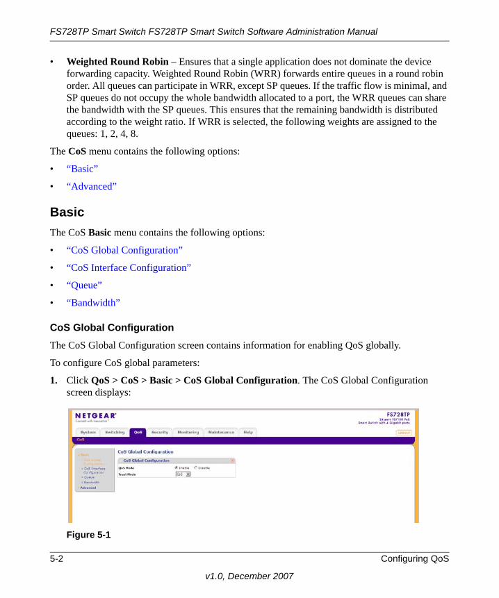
FS728TP Smart Switch FS728TP Smart Switch Software Administration Manual
• Weighted Round Robin – Ensures that a single application does not dominate the device forwarding capacity. Weighted Round Robin (WRR) forwards entire queues in a round robin order. All queues can participate in WRR, except SP queues. If the traffic flow is minimal, and SP queues do not occupy the whole bandwidth allocated to a port, the WRR queues can share the bandwidth with the SP queues. This ensures that the remaining bandwidth is distributed according to the weight ratio. If WRR is selected, the following weights are assigned to the queues: 1, 2, 4, 8.
The CoS menu contains the following options:
• “Basic”
• “Advanced”
BasicThe CoS Basic menu contains the following options:
• “CoS Global Configuration”
• “CoS Interface Configuration”
• “Queue”
• “Bandwidth”
CoS Global ConfigurationThe CoS Global Configuration screen contains information for enabling QoS globally.
To configure CoS global parameters:
1. Click QoS > CoS > Basic > CoS Global Configuration. The CoS Global Configuration screen displays:
Figure 5-1
5-2 Configuring QoS
v1.0, December 2007

FS728TP Smart Switch FS728TP Smart Switch Software Administration Manual
The CoS Global Configuration screen contains the following:
• QoS Mode – Select whether QoS is enabled or disabled on the device. The possible values are:
– Enable – Enable QoS globally.
– Disable – Disable QoS globally.
• Trust Mode – Select which packet fields to use for classifying packets entering the device. The possible Trust Mode field values are:
– CoS – Classify traffic based on the CoS (VPT) tag value.
– DSCP – Classify traffic based on the DSCP tag value.
2. Select the QoS Mode and Trust Mode in the provided fields.
3. Click Apply to update the device.
CoS Interface ConfigurationThe CoS Interface Configuration screen contains information for configuring the default CoS value on a selected interface. After CoS has been configured, the device original CoS default settings can be reassigned to the interface in the CoS Interface Configuration screen.
Configuring QoS 5-3
v1.0, December 2007

FS728TP Smart Switch FS728TP Smart Switch Software Administration Manual
To configure CoS interface parameters:
1. Click QoS > CoS > Basic > CoS Interface Configuration. The CoS Interface Configuration screen displays:
The CoS Interface Configuration screen contains the following:
• Interface – Displays the interface for which the global QoS parameters are defined.
• Default CoS – Select the default CoS value for incoming packets for which a VLAN priority (VPT) is not defined.
• Restore Defaults – Restore the factory CoS default settings to the selected port. The possible field values are:
– Checked – Restore the factory CoS default settings to the ports.
– Unchecked – Maintain the current CoS settings.
2. Select the interface.
3. Select the Default CoS value from the list in the provided field in the first row.
4. Check or uncheck the Restore Defaults box in the interface entry row.
Figure 5-2
5-4 Configuring QoS
v1.0, December 2007

FS728TP Smart Switch FS728TP Smart Switch Software Administration Manual
5. Click Apply to update the device.
QueueThe Queue screen contains fields for defining the QoS queue forwarding types.
To set the queue settings:
1. Click QoS > CoS > Basic > Queue. The Queue screen displays:
The Queue screen contains the following fields:
• Strict Priority – Select to specify traffic scheduling based strictly on the queue priority.
• WRR – Select to assign WRR weights to queues. The queue weights are preconfigured and are set to 1, 2, 4 and 8.
2. Select either Strict Priority or WRR to specify the traffic scheduling method.
3. Click Apply to update the device.
BandwidthAfter packets are assigned to a queue, a scheduling scheme can be assigned to an interface, using either:
• Committed Burst Size – Indicates the maximum number of data bits transmitted within a specific time interval.
• Committed Information Rate – Indicates the rate that data is transmitted. The rate is averaged over a minimum time increment.
The Bandwidth screen allows the user to define Ingress Rate Limit and Egress Shaping Rates.
Figure 5-3
Configuring QoS 5-5
v1.0, December 2007

FS728TP Smart Switch FS728TP Smart Switch Software Administration Manual
To define bandwidth settings:
1. Click QoS > CoS > Basic > Bandwidth. The Bandwidth screen displays:
The Bandwidth screen contains the following fields:
• Interface – Displays the ports for which the bandwidth settings are displayed.
• Ingress Rate Limit Status – Select whether rate limiting is defined on the interface. The possible field values are:
– Enable – Enable ingress rate limiting on the interface.
– Disable – Disable ingress rate limiting on the interface.
• Ingress Rate Limit – Enter the rate limit in kilobits per second. The possible field range is 70 to the maximum port speed. FE ports have a maximum speed of 100000 kilobits per second and GE ports have a maximum speed of 1000000 kilobits per second. The default value is 70 kilobits per second.
• Egress Shaping Rates Status – Select whether egress shaping is defined on the interface. The possible field values are:
– Enable – Enable egress shaping rate on the interface.
Figure 5-4
5-6 Configuring QoS
v1.0, December 2007

FS728TP Smart Switch FS728TP Smart Switch Software Administration Manual
– Disable – Disable egress shaping rate on the interface. This is the default value.
• Egress Shaping Rates CIR – Enter the Egress Shaping Committed Information Rate (CIR) in kilobits per second. The possible field range is 0 to 62500 for FE ports and 64 to 1000000 for GE ports.
2. Select the interface.
3. Choose either Enable or Disable in the Ingress Rate Limit Status provided field in the first row.
4. If you selected Enable in the Ingress Rate Limit Status field, enter the Ingress Rate Limit in the provided field in the first row.
5. Choose either Enable or Disable in the Egress Shaping Rate Status provided field in the first row.
6. If you selected Enable in the Egress Shaping Rate Status field, enter the Egress Shaping Rates CIR in the provided field in the first row.
7. Click Apply to update the device.
AdvancedThe CoS Advanced menu contains the following options:
• “CoS to Queue Mapping”
• “DSCP to Queue Mapping”
CoS to Queue MappingThe CoS to Queue Mapping screen contains fields for mapping CoS values to traffic queues.
Configuring QoS 5-7
v1.0, December 2007

FS728TP Smart Switch FS728TP Smart Switch Software Administration Manual
To map CoS values to queues:
1. Click QoS > CoS> Advanced > CoS to Queue Mapping. The CoS to Queue Mapping screen displays:
The CoS to Queue Mapping screen contains the following fields:
CoS to Queue Mapping
• CoS – Displays the CoS priority tag values, where 0 is the lowest and 7 is the highest.
• Queue – Select the traffic forwarding queue to which the CoS priority is mapped. Four traffic priority queues are supported (Lowest, Low, Normal and High). The High Queue is reserved for special traffic and is not recommended for use.
Restore Default Mapping
• Restore Defaults – Restore the device factory defaults for mapping CoS values to a forwarding queue. The possible field values are:
– Checked – Restore the factory default settings for mapping CoS values to a forwarding queue.
– Unchecked – Maintain the current CoS queue mapping settings.
2. Select the Queue values for each CoS value in the provided fields.
3. Check or uncheck the Restore Defaults box in the provided field.
4. Click Apply to update the device.
Figure 5-5
5-8 Configuring QoS
v1.0, December 2007

FS728TP Smart Switch FS728TP Smart Switch Software Administration Manual
DSCP to Queue MappingThe DSCP To Queue Mapping screen contains fields for mapping DSCP values to traffic queues. For example, a packet with a DSCP tag value of 1 can be assigned to queue 2.
To map DSCP values to queues:
1. Click QoS > CoS> Advanced > DSCP To Queue Mapping. The DSCP To Queue Mapping screen displays:
The DSCP To Queue Mapping screen contains the following fields:
DSCP to Queue Mapping
• DSCP In – Displays the incoming packet’s DSCP value. The following DSCP In values are predefined: 3, 11, 19, 27, 35, 43, 51, 59.
• Queue – Select the traffic-forwarding queue to which the DSCP is mapped. Four traffic priority queues are supported (Lowest, Low, Normal and High). The High Queue is reserved for special traffic and is not recommended for use.
Restore Default Mapping
Figure 5-6
Configuring QoS 5-9
v1.0, December 2007

FS728TP Smart Switch FS728TP Smart Switch Software Administration Manual
• Restore Defaults– Restore the DSCP Mapping device factory default values. The possible field values are:
– Checked – Restore the factory default settings for DSCP mapping values.
– Unchecked – Maintain the current DSCP mapping settings.
2. Select the Queue values for each DSCP In value in the provided fields.
3. Check or uncheck the Restore Defaults box in the provided field.
4. Click Apply to update the device.
5-10 Configuring QoS
v1.0, December 2007

Chapter 6Managing Security
Setting Security Configuration Options
The navigation pane at the top of the web browser interface contains a Security tab that enables you to manage your FS728TP Smart Switch with features under the following main menu options:
• “Management Security”
• “Port Authentication”
• “Traffic Control”
• “ACL”
The description that follows in this chapter describes configuring and managing security settings in the FS728TP Smart Switch.
Management Security
The Management Security menu contains the following options:
• “User Configuration”
• “RADIUS”
• “TACACS+”
• “Authentication List”
User ConfigurationThe User Configuration menu contains the following options:
• “Change Password”
6-1
v1.0, December 2007

FS728TP Smart Switch FS728TP Smart Switch Software Administration Manual
Change PasswordThe Change Password screen contains parameters for configuring device passwords. Authentication on this device uses only a password, not a username.
To change the device password:
1. Click Security > Management Security > User Configuration > Change Password. The Change Password screen displays:
The Change Password screen contains the following fields:
• User Name – Displays the User Name.
• Old Password – Enter the current password for accessing the system.
• New Password – Enter a new password for accessing the system.
• Retype New Password – Repeat the new password used to access the system.
2. Enter the Old Password, New Password and Retype New Password in the provided fields.
3. Click Apply to update the device.
RADIUSRemote Authorization Dial-In User Service (RADIUS) servers provide additional security for networks. RADIUS servers provide a centralized authentication method for web access.
The default parameters are user-defined, and are applied to newly defined RADIUS servers. If new default parameters are not defined, the system default values are applied to newly defined RADIUS servers.
Figure 6-1
6-2 Managing Security
v1.0, December 2007
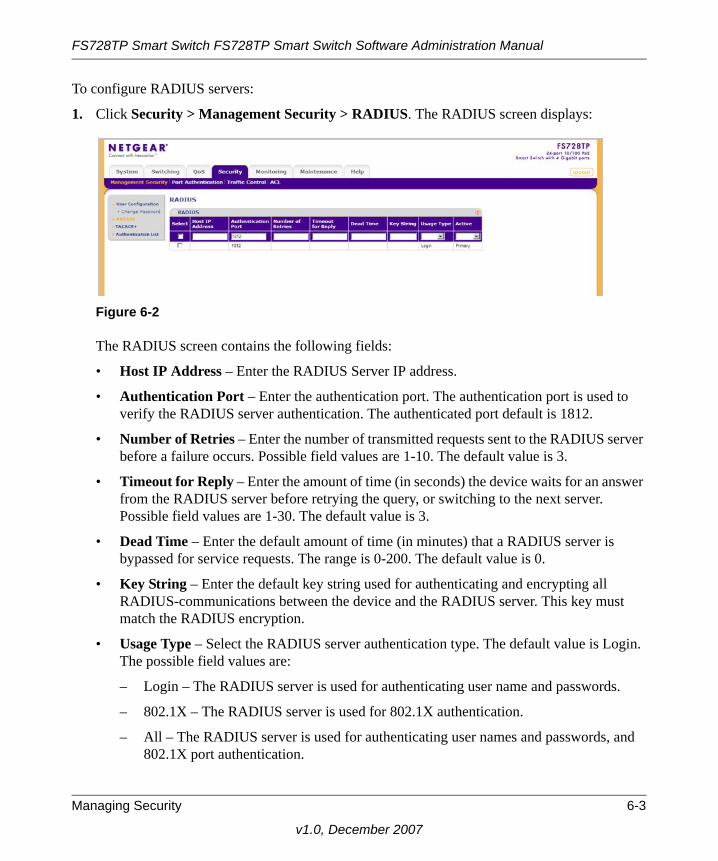
FS728TP Smart Switch FS728TP Smart Switch Software Administration Manual
To configure RADIUS servers:
1. Click Security > Management Security > RADIUS. The RADIUS screen displays:
The RADIUS screen contains the following fields:
• Host IP Address – Enter the RADIUS Server IP address.
• Authentication Port – Enter the authentication port. The authentication port is used to verify the RADIUS server authentication. The authenticated port default is 1812.
• Number of Retries – Enter the number of transmitted requests sent to the RADIUS server before a failure occurs. Possible field values are 1-10. The default value is 3.
• Timeout for Reply – Enter the amount of time (in seconds) the device waits for an answer from the RADIUS server before retrying the query, or switching to the next server. Possible field values are 1-30. The default value is 3.
• Dead Time – Enter the default amount of time (in minutes) that a RADIUS server is bypassed for service requests. The range is 0-200. The default value is 0.
• Key String – Enter the default key string used for authenticating and encrypting all RADIUS-communications between the device and the RADIUS server. This key must match the RADIUS encryption.
• Usage Type – Select the RADIUS server authentication type. The default value is Login. The possible field values are:
– Login – The RADIUS server is used for authenticating user name and passwords.
– 802.1X – The RADIUS server is used for 802.1X authentication.
– All – The RADIUS server is used for authenticating user names and passwords, and 802.1X port authentication.
Figure 6-2
Managing Security 6-3
v1.0, December 2007

FS728TP Smart Switch FS728TP Smart Switch Software Administration Manual
• Active – Select the priority in which the system performs authentication with a Radius Server. The system performs authentication initially with the Radius Primary Server, and if it fails, it performs authentication with the Radius Backup Server. The possible values are:
– Primary – Defines the RADIUS Primary Server.
– Backup – Defines the RADIUS Backup Server.
2. Select the RADIUS server entry.
3. Enter the Host IP Address, Authentication Port, Number of Retries, Timeout for Reply, Dead Time and Key String in the provided fields in the first row.
4. Select the Usage Type and Active server from the lists in the provided fields in the first row.
5. Click Apply to update the device.
To add a new RADIUS server entry:
1. Click Security > Management Security > RADIUS. The RADIUS screen displays.
2. Enter the Host IP Address, Authentication Port, Number of Retries, Timeout for Reply, Dead Time and Key String in the provided fields in the first row.
3. Select the Usage Type and Active server from the lists in the provided fields in the first row.
4. Click Add to update the device.
To remove a RADIUS server entry:
1. Click Security > Management Security > RADIUS. The RADIUS screen displays.
2. Select the RADIUS server entry.
3. Click Delete to remove the entry.
TACACS+Terminal Access Controller Access Control System (TACACS+) provides centralized security user access validation. The system supports up-to 2 TACACS+ servers.
TACACS+ provides a centralized user management system, while still retaining consistency with RADIUS and other authentication processes.
The TACACS+ protocol ensures network integrity through encrypted protocol exchanges between the client and TACACS+ server. The TACACS+ default parameters are user-assigned defaults. The default settings are applied to newly defined TACACS+ servers.
6-4 Managing Security
v1.0, December 2007

FS728TP Smart Switch FS728TP Smart Switch Software Administration Manual
If default values are not defined, the system defaults are applied to the new TACACS+ new servers.
To configure TACACS+ Settings:
1. Click Security > Management Security > TACACS+. The TACACS+ screen displays:
The TACACS+ screen contains the following fields:
• Host IP Address – Enter the TACACS+ Server IP address.
• Key String – Enter the default authentication and encryption key for TACACS+ communication between the device and the TACACS+ server.
• Authentication Port – Enter the port number via which the TACACS+ session occurs. The default port is port 49.
• Timeout for Reply – Enter the amount of time (in seconds) the device waits for an answer from the TACACS+ server before retrying the query, or switching to the next server. Possible field values are 1-30. The default value is 5.
• Single Connection – Select whether a single open connection between the host Authentication Port and the TACACS+ server is enabled or disabled. The possible field values are:
– Enable – Enable a single connection.
– Disable – Disable a single connection.
• Active – Select whether this server is the primary or backup TACACS+ server used for authentication. The possible values are:
– Primary – Define the TACACS+ Primary Server.
Figure 6-3
Managing Security 6-5
v1.0, December 2007

FS728TP Smart Switch FS728TP Smart Switch Software Administration Manual
– Backup – Define the TACACS+ Backup Server.
2. Select the TACACS+ server entry.
3. Enter the Host IP Address, Key String, Authentication Port and Timeout for Reply in the provided fields in the first row.
4. Select the Single Connection status and Active server from the lists in the provided fields in the first row.
5. Click Apply to update the device.
To add a new TACACS+ server entry:
1. Click Security > Management Security > TACACS+. The TACACS+ screen displays.
2. Enter the Host IP Address, Key String, Authentication Port and Timeout for Reply in the provided fields in the first row.
3. Select the Single Connection status and Active server from the lists in the provided fields in the first row.
4. Click Add to update the device.
To remove a TACACS+ server entry:
1. Click Security > Management Security > TACACS+. The TACACS+ screen displays.
2. Select the TACACS+ server entry.
3. Click Delete to remove the entry.
Authentication ListThe Authentication List screen contains information for defining an authentication method for the selected Authentication List. For example, if the user selects TACACS+ as the first entry, None as the second, this causes authentication to first occur at the TACACS+ server. If the TACACS+ server is inaccessible or not defined, the session is permitted.
Once the Authentication List is defined as Local, it is not possible to define an alternative authentication method as it is a built-in system authentication method.
In order to configure RADIUS/TACACS+ authentication, the user name should be configured as $enab15$ on the RADIUS/TACACS+ server.
6-6 Managing Security
v1.0, December 2007

FS728TP Smart Switch FS728TP Smart Switch Software Administration Manual
To configure the Authentication List method:
1. Click Security > Management Security > Authentication List. The Authentication List screen displays:
The Authentication List screen contains the following fields:
• 1,2,3 – Select the order in which authentication is applied. The possible field values are:
– TACACS+ – Authenticate the user at the TACACS+ server. For more information, see “TACACS+”.
– RADIUS – Authenticate the user at the RADIUS server. For more information, see “RADIUS”.
– Local – Authenticate the user at the device level. The device checks the user name and password for authentication
– None – Assign no authentication method to the authentication list.
2. Select the Authentication List entry.
3. Select the order of authentication (1,2,3) from the lists in the provided fields in the first row.
4. Click Apply to update the device.
Port Authentication
The Port Authentication menu contains the following options:
• “Basic”
• “Advanced”
Figure 6-4
Managing Security 6-7
v1.0, December 2007

FS728TP Smart Switch FS728TP Smart Switch Software Administration Manual
BasicThe Port Authentication Basic menu contains the following option:
• “802.1X Configuration”
802.1X ConfigurationThe Basic 802.1X Configuration screen allows network managers to configure network authentication parameters. In addition, Guest VLANs are enabled from the Basic 802.1X Configuration screen.
To define the 802.1X configuration:
1. Click Security > Port Authentication > Basic > 802.1X Configuration. The Basic 802.1X Configuration screen displays:
The Basic 802.1X Configuration screen contains the following fields:
• Port Based Authentication State – Select whether port-based authentication is enabled or disabled on the device. The possible field values are:
– Disable – Disable port-based authentication on the device.
– Enable – Enable port-based authentication on the device.
• Authentication Method – Select the authentication method used for port authentication. The possible field values are:
– RADIUS, None – Port authentication is first attempted through the RADIUS server. If the RADIUS server is inaccessible or not defined, then no authentication method (None) is used and the session is permitted.
– RADIUS – Port authentication is through the RADIUS server.
Figure 6-5
6-8 Managing Security
v1.0, December 2007

FS728TP Smart Switch FS728TP Smart Switch Software Administration Manual
– None – No authentication method is used to authenticate the port.
• Guest VLAN – Select whether the Guest VLAN is enabled or disabled on the device. The default VLAN cannot be defined as a Guest VLAN. The possible field values are:
– Disable – Disable the Guest VLAN on the device. This is the default value.
– Enable – Enable using a Guest VLAN for unauthorized ports. If a Guest VLAN is enabled, the unauthorized port automatically joins the VLAN selected in the VLAN List field.
• Guest VLAN ID – Select the guest VLAN ID from the list of the currently defined VLANs.
2. Select Disable or Enable for the Port Based Authentication State in the provided field.
3. If you selected Enable for the Port Based Authentication State, then select the Authentication Method from the list in the provided field.
4. Select Disable or Enable for the Guest VLAN status in the provided field.
5. If you selected Enable for the Guest VLAN field, then select the VLAN ID from the list in the provided field.
6. Click Apply to update the device.
AdvancedThe Port Authentication Advanced menu contains the following options:
• “802.1X Configuration”
• “Port Authentication”
802.1X ConfigurationThe Advanced 802.1X Configuration screen allows network managers to configure network authentication parameters. In addition, Guest VLANs are enabled from the Advanced 802.1X configuration screen.
Managing Security 6-9
v1.0, December 2007

FS728TP Smart Switch FS728TP Smart Switch Software Administration Manual
To define the 802.1X configuration:
1. Click Security > Port Authentication > Advanced > 802.1X configuration. The Advanced 802.1X Configuration screen displays:
The Advanced 802.1X Configuration screen contains the following fields:
• Port Based Authentication State – Enable port-based authentication on the device. The possible field values are:
– Disable – Disable port-based authentication on the device.
– Enable – Enable port-based authentication on the device.
• Authentication Method – Enter the authentication method used for port authentication. The possible field values are:
– RADIUS, None – Port authentication is first attempted through the RADIUS server. If the RADIUS server is inaccessible or not defined, then no authentication method (None) is used and the session is permitted.
– RADIUS – Port authentication is through the RADIUS server.
– None – No authentication method is used to authenticate the port.
• Guest VLAN – Enter whether the Guest VLAN is enabled on the device. The possible field values are:
– Disable – Disable Guest VLAN on the device. This is the default value.
– Enable – Enable using a Guest VLAN for unauthorized ports. If a Guest VLAN is enabled, the unauthorized port automatically joins the VLAN selected in the VLAN List field.
Figure 6-6
6-10 Managing Security
v1.0, December 2007
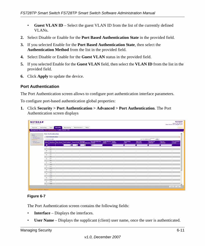
FS728TP Smart Switch FS728TP Smart Switch Software Administration Manual
• Guest VLAN ID – Select the guest VLAN ID from the list of the currently defined VLANs.
2. Select Disable or Enable for the Port Based Authentication State in the provided field.
3. If you selected Enable for the Port Based Authentication State, then select the Authentication Method from the list in the provided field.
4. Select Disable or Enable for the Guest VLAN status in the provided field.
5. If you selected Enable for the Guest VLAN field, then select the VLAN ID from the list in the provided field.
6. Click Apply to update the device.
Port AuthenticationThe Port Authentication screen allows to configure port authentication interface parameters.
To configure port-based authentication global properties:
1. Click Security > Port Authentication > Advanced > Port Authentication. The Port Authentication screen displays
The Port Authentication screen contains the following fields:
• Interface – Displays the interfaces.
• User Name – Displays the supplicant (client) user name, once the user is authenticated.
Figure 6-7
Managing Security 6-11
v1.0, December 2007
FS728TP Smart Switch FS728TP Smart Switch Software Administration Manual
• Port Control – Select the port authorization state.
– Auto – The port control is Auto and a single client has been authenticated via the port.
– Authorized – The port control is Forced Authorized, and clients have full port access.
– Unauthorized – Either the port control is force Unauthorized, or the port control is Auto but a client has not been authenticated via the port.
• Guest VLAN – Select whether the Guest VLAN is enabled or disabled on the port. The default VLAN cannot be defined as a Guest VLAN. The possible field values are:
– Enable – Enable using a Guest VLAN for unauthorized ports. If a Guest VLAN is enabled, the unauthorized port automatically joins the VLAN selected in the VLAN List field.
– Disable – Disable the Guest VLAN on the port. This is the default value.
• Periodic Reauthentication – Select whether periodic port reauthentication is enabled or disabled. The possible field values are:
– Enable – Enable periodic port reauthentication.
– Disable – Disable port reauthentication. This is the default value.
• Reauthentication Period – Enter the time span (in seconds) in which the selected port is reauthenticated. The field default is 3600 seconds.
• Authenticator State – Displays whether immediate port reauthentication is enabled or disabled. The possible field values are:
– Enable – Immediate port reauthentication is enabled.
– Disable – Immediate port reauthentication is disabled. This is the default value.
• Quiet Period – Enter the number of seconds that the device remains in the quiet state following a failed authentication exchange. The possible field range is 0-65535. The field default is 60 seconds.
• Resending EAP – Enter the amount of time (in seconds) that lapses before EAP requests are resent. The field default is 30 seconds.
• Max EAP Requests – Enter the total amount of EAP requests sent. If a response is not received after the defined period, the authentication process is restarted. The field default is 2 retries.
• Supplicant Timeout – Enter the amount of time (in seconds) that lapses before EAP requests are resent to the supplicant. The field default is 30 seconds.
6-12 Managing Security
v1.0, December 2007
FS728TP Smart Switch FS728TP Smart Switch Software Administration Manual
• Server Timeout – Enter the amount of time (in seconds) that lapses before the device re-sends a request to the authentication server. The field default is 30 seconds.
• Termination Cause – Displays the reason port authentication was terminated.
2. Select the interface.
3. Select the Port Control state, Guest VLAN mode and Periodic Reauthentication status in the provided fields in the first row.
4. If you selected Enable as the Periodic Reauthentication status, enter the Reauthentication Period in the provided field in the first row.
5. Enter the Quiet Period, Resending EAP time, Max EAP Requests, Supplicant Timeout and Server Timeout in the provided field in the first row.
6. Click Apply to update the device.
Traffic Control
The Traffic Control menu contains the following options:
• “Storm Control”
• “Port Security”
Storm ControlStorm Control limits the amount of Multicast and Broadcast frames accepted and forwarded by the device. When Layer 2 frames are forwarded, Broadcast, and Multicast frames are flooded to all ports on the relevant VLAN. This occupies bandwidth and loads all nodes on all ports.
A Broadcast Storm is a result of an excessive amount of broadcast messages simultaneously transmitted across a network by a single port. Forwarded message responses are heaped onto the network, straining network resources or causing the network to time out.
Storm control can be enabled per port by defining the packet type and the rate the packets are transmitted. The system measures the incoming Broadcast and Multicast frame rates separately on each port, and discards the frames when the rate exceeds a user-defined rate. By default, Storm Control is enabled on all ports for Broadcast packets with a threshold of 200 kbps. Storm Control is enabled by default.
The Storm Control screen provides fields for configuring broadcast storm control.
Managing Security 6-13
v1.0, December 2007

FS728TP Smart Switch FS728TP Smart Switch Software Administration Manual
To configure storm control:
1. Click Security > Traffic Control > Storm Control. The Storm Control screen displays:
The Storm Control screen contains the following fields:
• Interface – Displays the port number for which the storm control information is displayed.
• Broadcast Control – Select whether storm control is enabled or disabled on the interface according to Broadcast mode. The possible field values are:
– Enable – Enable storm control on the interface. This is the default value.
– Disable – Disable storm control on the interface.
• Broadcast Mode – Select the Broadcast mode on the interface. The possible field values are:
– Multicast & Broadcast – Count Broadcast and Multicast traffic together.
– Broadcast Only – Count Broadcast traffic only.
Figure 6-8
6-14 Managing Security
v1.0, December 2007

FS728TP Smart Switch FS728TP Smart Switch Software Administration Manual
• Broadcast Rate Threshold – Enter the maximum rate (kilobits per second) at which broadcast packets are forwarded. The range is 70-285000 kbps. The default value is 200 kbps.
2. Select the interface.
3. Select Enable or Disable Broadcast Control in the provided field in the first row.
4. If you selected Enable Broadcast Control, select the Broadcast Mode from the list in the provided field in the first row.
5. If you selected Enable Broadcast Control, enter the Broadcast Rate Threshold in the provided field in the first row.
6. Click Apply to update the device.
Port SecurityNetwork security can be increased by limiting access on a specific port only to users with specific MAC addresses. The MAC addresses can be dynamically learned or statically configured. Locked port security monitors both received and learned packets that are received on specific ports. Access to the locked port is limited to users with specific MAC addresses. These addresses are either manually defined on the port, or learned on that port up to the point when it is locked. When a packet is received on a locked port and the packet source MAC address is not tied to that port (either it was learned on a different port, or it is unknown to the system), the protection mechanism is invoked. It provides the following options for unauthorized packets arriving at a locked port:
• Forwarded
• Discarded with no trap
• Discarded with a trap
• Shuts down the port
Locked port security also enables storing a list of MAC addresses in the configuration file. The MAC address list can be restored after the device has been reset.
Managing Security 6-15
v1.0, December 2007
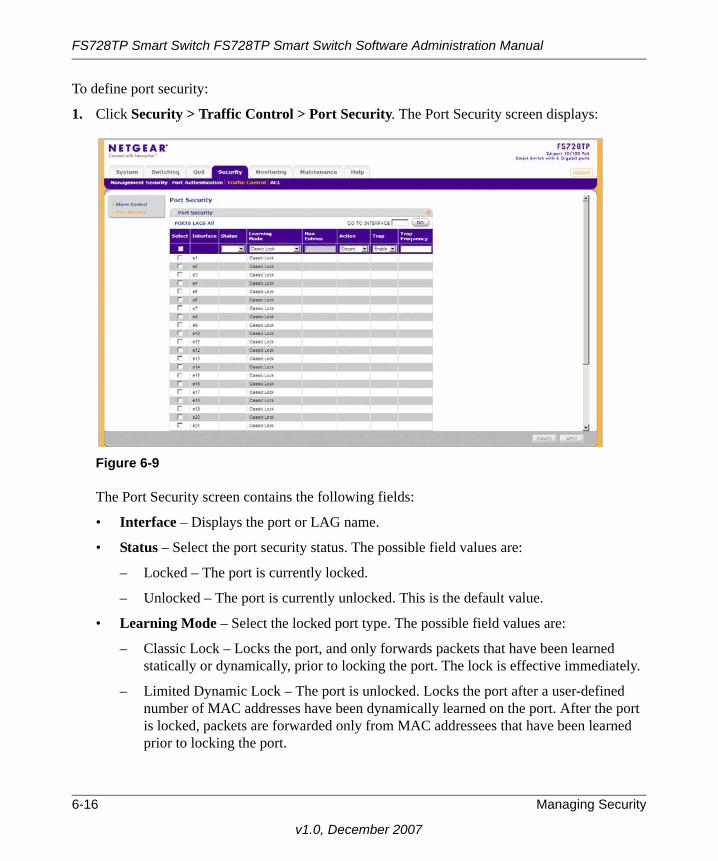
FS728TP Smart Switch FS728TP Smart Switch Software Administration Manual
To define port security:
1. Click Security > Traffic Control > Port Security. The Port Security screen displays:
The Port Security screen contains the following fields:
• Interface – Displays the port or LAG name.
• Status – Select the port security status. The possible field values are:
– Locked – The port is currently locked.
– Unlocked – The port is currently unlocked. This is the default value.
• Learning Mode – Select the locked port type. The possible field values are:
– Classic Lock – Locks the port, and only forwards packets that have been learned statically or dynamically, prior to locking the port. The lock is effective immediately.
– Limited Dynamic Lock – The port is unlocked. Locks the port after a user-defined number of MAC addresses have been dynamically learned on the port. After the port is locked, packets are forwarded only from MAC addressees that have been learned prior to locking the port.
Figure 6-9
6-16 Managing Security
v1.0, December 2007

FS728TP Smart Switch FS728TP Smart Switch Software Administration Manual
• Max Entries – Enter the maximum number of MAC addresses that can be learned on the port. The Max Entries field is enabled only if the Limited Dynamic Lock mode is selected. The range is 1-128 entries. The default value is 1.
• Action – Select the action to be applied to packets arriving on a locked port. The possible field values are:
– Forward – Forwards packets from an unknown source without learning the MAC address.
– Discard – Discards packets from any unlearned source. This is the default value.
– Shutdown – Discards packets from any unlearned source and shuts down the port. The port remains shut down until reactivated or until the device is reset.
• Trap – Select whether traps are enabled or disabled when a packet from an unknown source is received on a locked port. The possible field values are:
– Enable – Enable traps.
– Disable – Disable traps. This is the default value.
• Trap Frequency (Sec) – Enter the frequency at which traps are sent. The field format is in seconds. The range is 1-1,000,000. The default value is 10 seconds.
2. Select the port security Status, Learning Mode, Action and Trap status from the lists in the provided fields in the first row.
3. Enter the Max Entries and Trap Frequency in the provided fields in the first row.
4. Click Apply to update the device.
ACL
Access Control Lists (ACL) allow network managers to define classification actions and rules for specific ingress ports. Packets entering an ingress port, with an active ACL, are either admitted or denied entry and the ingress port is disabled. If they are denied entry, the user can disable the port.
The ACL menu contains the following options:
• “MAC ACL”
• “MAC Rules”
• “MAC Binding Configuration”
• “IP ACL”
Managing Security 6-17
v1.0, December 2007

FS728TP Smart Switch FS728TP Smart Switch Software Administration Manual
• “IP Rules”
• “IP Binding Configuration”
• “Binding Table”
MAC ACLThe MAC ACL screen allows a MAC Based ACL to be defined.
To view or rename MAC Based ACLs:
1. Click Security > ACL > MAC ACL. The MAC Configuration screen displays:
The MAC Configuration screen contains the following fields:
MAC Configuration
• Current number of ACL – Displays the current number of user-defined ACLs.
MAC ACL Table
• Name – Enter the user-defined MAC based ACL name.
• Number of Rules – Displays the current number of rules in the ACL.
2. Select the ACL entry.
3. Enter the new ACL Name in the provided field in the first row.
4. Click Apply to update the device.
Figure 6-10
6-18 Managing Security
v1.0, December 2007

FS728TP Smart Switch FS728TP Smart Switch Software Administration Manual
To add a new MAC-based ACL entry:
1. Click Security > ACL > MAC ACL. The MAC Configuration screen displays.
2. Enter the ACL Name in the provided field in the first row.
3. Click Add to update the device.
To remove a MAC-based ACL entry:
1. Click Security > ACL > MAC ACL. The MAC Configuration screen displays.
2. Select the ACL entry.
3. Click Delete to remove the entry.
MAC RulesThe MAC Rules screen allows a MAC Rule to be defined within a configured ACL. Rules can be added only if the ACL is not bound to an interface.
To define MAC Rules:
1. Click Security > ACL > MAC Rules. The MAC Rules screen displays:
The MAC Rules screen contains the following fields:
MAC ACL
• ACL Name – Select the ACL Name from the list.
Rule Table
Figure 6-11
Managing Security 6-19
v1.0, December 2007

FS728TP Smart Switch FS728TP Smart Switch Software Administration Manual
• Priority – Defines the rule priority. When the packet is matched to a rule, user groups are either granted permission or denied device management access. The rule number is essential to matching packets to rules, as packets are matched on a first-fit basis.
• Source MAC Address – Enter the source MAC Address.
• Source Mask – Enter the mask of the new source MAC address.
• Destination MAC Address – Enter the destination MAC address.
• Destination Mask – Enter the mask of the new destination MAC address.
• VLAN ID – Enter the VLAN ID to which the MAC address is attached in the MAC Rules database.
• Action – Select the action applied to packets with MAC addresses that have been filtered. The possible field values are:
– Permit – Permit access to the device.
– Deny – Deny access to packets originating from the blocked MAC address.
– Shutdown – Drop packets that meet the ACL criteria, and disable the port to which the packet was addressed.
2. Select the ACL Name from the list in the provided field.
3. Select the rule entry.
4. Enter the provided fields in the first row.
5. Click Apply to update the device.
To add a MAC rule:
1. Click Security > ACL > MAC Rules. The MAC Rules screen displays.
2. Select the ACL Name from the list in the provided field.
3. Enter the provided fields in the first row.
4. Click Add to update the device.
To delete a MAC rule:
1. Click Security > ACL > MAC Rules. The MAC Rules screen displays.
2. Select the ACL Name from the list in the provided field.
3. Select the rule entry.
4. Click Delete to remove the entry.
6-20 Managing Security
v1.0, December 2007

FS728TP Smart Switch FS728TP Smart Switch Software Administration Manual
MAC Binding ConfigurationTo bind interfaces to an ACL:
1. Click Security > ACL > MAC Binding Configuration. The MAC Binding Configuration screen displays:
The MAC Binding Configuration screen contains the following fields:
MAC Binding Configuration
• ACL Name – Select the ACL Name for viewing and modifying ACL bound interfaces.
Port Selection Table
2. Select the interfaces for which the ACLs are bound.
3. Select the ACL Name from the list in the provided field.
4. Select the interfaces to bind to the selected ACL Name by one of the following methods.
a. Click on the port’s or LAG’s gold bar to display the associated interfaces, and then select the interfaces to bind by clicking on the boxes below the interfaces.
or
b. Click on the port’s or LAG’s quick box to select all the associated interfaces.
5. Click Apply to update the device.
Figure 6-12
Managing Security 6-21
v1.0, December 2007

FS728TP Smart Switch FS728TP Smart Switch Software Administration Manual
IP ACLThe IP ACL screen allows an IP Based ACL to be defined.
To view or rename IP Based ACLs:
1. Click Security > ACL > IP ACL. The IP ACL screen displays:
The IP ACL screen contains the following fields:
IP ACL
• Current number of ACL – Displays the current number of user-defined ACLs.
IP ACL Table
• Name – Enter the user-defined IP based ACL name.
• Number of Rules – Displays the current number of rules in the ACL.
2. Select the ACL entry.
3. Enter the new ACL Name in the provided field in the first, editable row.
4. Click Apply to update the device.
To add a new IP-based ACL entry:
1. Click Security > ACL > IP ACL. The IP ACL screen displays.
2. Click Add to create a new entry or duplicate an existing entry.
3. Select the ACL entry.
4. Enter the ACL Name in the provided field in the first, editable row.
Figure 6-13
6-22 Managing Security
v1.0, December 2007

FS728TP Smart Switch FS728TP Smart Switch Software Administration Manual
5. Click Apply to update the device.
To remove an IP-based ACL entry:
1. Click Security > ACL > IP ACL. The IP ACL screen displays.
2. Select the ACL entry.
3. Click Delete to remove the entry.
IP RulesThe IP Rules screen allows an IP Rule to be defined within a configured ACL. Rules can be added only if the ACL is not bound to an interface.
To define IP Rules:
1. Click Security > ACL > IP Rules. The IP Rules screen displays:
The IP Rules screen contains the following fields:
IP ACL
• ACL Name – Select the ACL Name from the list.
IP Rules
• Priority – Enter the rule priority. When the packet is matched to a rule, user groups are either granted permission or denied device management access. The rule number is essential to matching packets to rules, as packets are matched on a first-fit basis.
• Protocol ID – Enter the protocol in the rule to which the packet is matched.
Figure 6-14
Managing Security 6-23
v1.0, December 2007

FS728TP Smart Switch FS728TP Smart Switch Software Administration Manual
• Source IP Address – Enter the source IP Address.
• Source Mask – Enter the mask of the new source IP address.
• Destination IP Address – Enter the destination IP address.
• Destination Mask – Enter the mask of the new destination IP address.
• Source Port – Enter the source port that is matched to packets.
• Destination Port – Enter the destination port that is matched to packets.
• Action – Select the action applied to packets with IP addresses that have been filtered. The possible field values are:
– Permit – Permit access to the device.
– Denied – Deny access to packets originating from the blocked IP address.
– Shutdown – Drop packets that meet the ACL criteria, and disable the port to which the packet was addressed.
2. Select the ACL Name from the list in the provided field.
3. Select the rule entry.
4. Enter the provided fields in the first row.
5. Click Apply to update the device.
To add an IP rule:
1. Click Security > ACL > IP Rules. The IP Rules screen displays.
2. Select the ACL Name from the list in the provided field.
3. Click Add to create a new entry or duplicate an existing entry.
4. Select the added entry.
5. Enter the provided fields in the first row.
6. Click Apply to update the device.
To delete an IP rule:
1. Click Security > ACL > IP Rules. The IP Rules screen displays.
2. Select the ACL Name from the list in the provided field.
3. Select the rule entry.
4. Click Delete to remove the entry.
6-24 Managing Security
v1.0, December 2007

FS728TP Smart Switch FS728TP Smart Switch Software Administration Manual
IP Binding ConfigurationTo bind interfaces to an ACL:
1. Click Security > ACL > IP Binding Configuration. The IP Binding Configuration screen displays:
The IP Binding Configuration screen contains the following fields:
IP Binding Configuration
• ACL Name – Select the ACL Name for viewing and modifying ACL bound interfaces.
Port Selection Table
• Select the interfaces for which the ACLs are bound.
2. Select the ACL Name from the list in the provided field.
3. Select the interfaces to bind to the selected ACL Name by one of the following methods.
a. Click on the port or LAG gold bar to display the associated interfaces, and then select the interfaces to bind by clicking on the boxes below the interfaces.
or
b. Click on the port’s or LAG’s quick box to select all the associated interfaces.
4. Click Apply to update the device.
Figure 6-15
Managing Security 6-25
v1.0, December 2007

FS728TP Smart Switch FS728TP Smart Switch Software Administration Manual
Binding TableTo view the ACL Binding Table:
1. Click Security > ACL > Binding Table. The Binding Table screen displays:
The Binding Table screen contains the following fields:
Interface Binding Table
• Interface – Displays the interfaces for which the ACLs are bound.
• ACL Name – Displays the ACL Name.
• ACL Type – Displays the ACL Type. The possible field values are:
– IP – The ACL is IP address based.
– MAC – The ACL is MAC address based.
Figure 6-16
6-26 Managing Security
v1.0, December 2007

Chapter 7Monitoring the Switch
Setting Monitoring Options
The navigation pane at the top of the web browser interface contains a Monitoring tab that enables you to manage your FS728TP Smart Switch with features under the following main menu options:
• “Logs”
• “RMON”
• “Port Mirroring”
The description that follows in this chapter describes configuring and managing monitoring settings in the FS728TP Smart Switch.
Logs
Event messages have a unique format, as per the SYSLOG RFC recommended message format for all error reporting, for example, Syslog+ local device reporting. Messages are assigned a severity code, and include a message mnemonic, which identifies the source application generating the message. Messages are filtered based on their urgency or relevancy. The following table contains the Log Severity Levels:
Table 7-1. Severity Levels
Severity Severity Level Severity Level Description
Emergency 0 The system is not functioning.
Alert 1 The system needs immediate attention.
Critical 2 The system is in a critical state.
Error 3 A system error has occurred.
Warning 4 A system warning is logged.
Notice 5 The system is functioning properly, but a system notice is logged.
Informational 6 Device information is provided.
Debug 7 Detailed log information is provided.
7-1
v1.0, December 2007

FS728TP Smart Switch FS728TP Smart Switch Software Administration Manual
This section provides information for managing logs. The logs enable viewing device events in real time, and recording the events for later usage. Logs record and manage events and report errors and informational messages.
The Logs menu contains the following options:
• “Logs Configuration”
• “Log Filter”
• “Memory Log”
• “Flash Log”
• “Server Log”
Logs ConfigurationThe Log Configuration screen contains fields for enabling and disabling logs globally.
To enable or disable event logging:
1. Click Monitoring > Logs > Logs Configuration. The Logs Configuration screen displays:
The Logs Configuration screen contains the following field:
• Logging State – Select whether to enable or disable the device global logs for Cache, File and Server Logs. Console logs are enabled by default. The possible field values are:
– Disable – Disable device logs.
– Enable – Enable device logs.
2. Select either Enable or Disable as the Logging State in the provided field.
3. Click Apply to update the device.
Figure 7-1
7-2 Monitoring the Switch
v1.0, December 2007
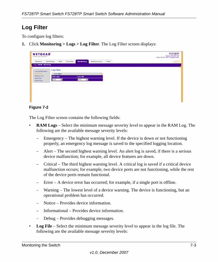
FS728TP Smart Switch FS728TP Smart Switch Software Administration Manual
Log FilterTo configure log filters:
1. Click Monitoring > Logs > Log Filter. The Log Filter screen displays:
The Log Filter screen contains the following fields:
• RAM Logs – Select the minimum message severity level to appear in the RAM Log. The following are the available message severity levels:
– Emergency – The highest warning level. If the device is down or not functioning properly, an emergency log message is saved to the specified logging location.
– Alert – The second highest warning level. An alert log is saved, if there is a serious device malfunction; for example, all device features are down.
– Critical – The third highest warning level. A critical log is saved if a critical device malfunction occurs; for example, two device ports are not functioning, while the rest of the device ports remain functional.
– Error – A device error has occurred; for example, if a single port is offline.
– Warning – The lowest level of a device warning. The device is functioning, but an operational problem has occurred.
– Notice – Provides device information.
– Informational – Provides device information.
– Debug – Provides debugging messages.
• Log File – Select the minimum message severity level to appear in the log file. The following are the available message severity levels:
Figure 7-2
Monitoring the Switch 7-3
v1.0, December 2007

FS728TP Smart Switch FS728TP Smart Switch Software Administration Manual
– Emergency – The highest warning level. If the device is down or not functioning properly, an emergency log message is saved to the specified logging location.
– Alert – The second highest warning level. An alert log is saved, if there is a serious device malfunction; for example, all device features are down.
– Critical – The third highest warning level. A critical log is saved if a critical device malfunction occurs; for example, two device ports are not functioning, while the rest of the device ports remain functional.
– Error – A device error has occurred; for example, if a single port is offline.
– Warning – The lowest level of a device warning. The device is functioning, but an operational problem has occurred.
– Notice – Provides device information.
– Informational – Provides device information.
– Debug – Provides debugging messages.
2. Select the minimum severity level for RAM logs.
3. Select the minimum severity level for FLASH logs.
4. Click Apply to update the device.
Memory LogThe Memory Log screen contains all system logs in a chronological order that are saved in RAM (Cache).
7-4 Monitoring the Switch
v1.0, December 2007

FS728TP Smart Switch FS728TP Smart Switch Software Administration Manual
To view the Memory Log screen:
1. Click Monitoring > Logs > Memory Log. The Memory Log screen displays:
The Memory Log screen contains the following fields:
• Log Index – Displays the log number.
• Log Time – Displays the time at which the log was generated.
• Severity – Displays the log severity and urgency level. The following are the available log severity levels:
– Emergency – The highest warning level. If the device is down or not functioning properly, an emergency log message is saved to the specified logging location.
– Alert – The second highest warning level. An alert log is saved, if there is a serious device malfunction; for example, all device features are down.
– Critical – The third highest warning level. A critical log is saved if a critical device malfunction occurs; for example, two device ports are not functioning, while the rest of the device ports remain functional.
– Error – A device error has occurred; for example, if a single port is offline.
– Warning – The lowest level of a device warning. The device is functioning, but an operational problem has occurred.
– Notice – Provides device information.
– Informational – Provides device information.
– Debug – Provides debugging messages.
Figure 7-3
Monitoring the Switch 7-5
v1.0, December 2007

FS728TP Smart Switch FS728TP Smart Switch Software Administration Manual
• Description – Displays the log message text.
2. Click REFRESH or CLEAR LOGS to refresh or reset the Memory Logs screen.
Flash LogThe Flash Log screen contains information about log entries saved to the log file in Flash, including the time the log was generated, the log severity, and a description of the log message. The message log is available after reboot.
To view the message logs in Flash:
1. Click Monitoring > Logs > Flash Log. The Flash Log screen displays:
The Flash Log screen contains the following fields:
• Log Index – Displays the log number.
• Log Time – Displays the time at which the log was generated.
• Severity – Displays the log severity and urgency level. The following are the available log severity levels:
Figure 7-4
7-6 Monitoring the Switch
v1.0, December 2007

FS728TP Smart Switch FS728TP Smart Switch Software Administration Manual
– Emergency – The highest warning level. If the device is down or not functioning properly, an emergency log message is saved to the specified logging location.
– Alert – The second highest warning level. An alert log is saved, if there is a serious device malfunction; for example, all device features are down.
– Critical – The third highest warning level. A critical log is saved if a critical device malfunction occurs; for example, two device ports are not functioning, while the rest of the device ports remain functional.
– Error – A device error has occurred; for example, if a single port is offline.
– Warning – The lowest level of a device warning. The device is functioning, but an operational problem has occurred.
– Notice – Provides device information.
– Informational – Provides device information.
– Debug – Provides debugging messages.
• Description – Displays the log message text.
2. Click Refresh or Clear Logs to refresh or reset the Flash Logs screen.
Server LogThe Server Log screen contains information for viewing and configuring the remote log servers. New log servers can be defined and the log severity sent to each server.
To configure remote log servers:
1. Click Monitoring > Logs > Server Log. The Server Log screen displays:
Figure 7-5
Monitoring the Switch 7-7
v1.0, December 2007

FS728TP Smart Switch FS728TP Smart Switch Software Administration Manual
The Server Log screen contains the following fields:
• Server IP – Enter the server’s IP address to which logs can be sent.
• UDP Port – Enter the UDP port to which the server logs are sent. The possible range is 1 – 65535. The default value is 514.
• Facility – Select an application from which system logs are sent to the remote server. Only one facility can be assigned to a single server. If a second facility level is assigned, the first facility is overridden. All applications defined for a device utilize the same facility on a server. The field default is Local 0. The possible field values are Local 0 - Local 7.
• Description – Enter a user-defined server description.
• Minimum Severity – Select the minimum severity level for which logs are sent to the server. For example, if Notice is selected, all logs with a severity level of Notice and higher are sent to the remote server. The default value is Informational. The possible field values are:
– Emergency – The highest warning level. If the device is down or not functioning properly, an emergency log message is saved to the specified logging location.
– Alert – The second highest warning level. An alert log is saved, if there is a serious device malfunction; for example, all device features are down.
– Critical – The third highest warning level. A critical log is saved if a critical device malfunction occurs; for example, two device ports are not functioning, while the rest of the device ports remain functional.
– Error – A device error has occurred; for example, if a single port is offline.
– Warning – The lowest level of a device warning. The device is functioning, but an operational problem has occurred.
– Notice – Provides device information.
– Informational – Provides device information.
– Debug – Provides debugging messages.
2. Select the server entry.
3. Enter the Server IP address in the provided field in the first row.
4. Enter the UDP Port number in the provided field in the first row.
5. Select the Facility assigned to the server from the list in the provided field in the first row.
6. Enter an optional server Description in the provided field in the first row.
7-8 Monitoring the Switch
v1.0, December 2007

FS728TP Smart Switch FS728TP Smart Switch Software Administration Manual
7. Select the Minimum Severity level message sent to the server from the list in the provided field in the first row.
8. Click Apply to update the device.
To add a remote log server:
1. Click Monitoring > Logs > Server Log. The Server Log screen displays.
2. Enter the Server IP address in the provided field in the first row.
3. Enter the UDP Port number in the provided field in the first row.
4. Select the Facility assigned to the server from the list in the provided field in the first row.
5. Enter an optional server Description in the provided field in the first row.
6. Select the Minimum Severity level message sent to the server from the list in the provided field in the first row.
7. Click Add to update the device.
To remove a remote log server:
1. Click Monitoring > Logs > Server Log. The Server Log screen displays.
2. Select the log server entry.
3. Click Delete to remove the log server entry.
RMON
This section contains information for viewing Remote Monitoring Statistics. RMON Statistics allow network managers to view network traffic information from a single workstation.
The RMON menu contains the following options:
• “Basic”
• “Advanced”
BasicThe RMON Basic menu contains the following options:
• “Statistics”
Monitoring the Switch 7-9
v1.0, December 2007

FS728TP Smart Switch FS728TP Smart Switch Software Administration Manual
StatisticsThe RMON Basic Statistics screen contains fields for viewing information about device utilization and errors that occurred on the device.
To view RMON Basic Statistics:
1. Click Monitoring > RMON > Basic > Statistics. The RMON Basic Statistics screen displays:
The RMON Basic Statistics screen contains the following fields:
• Interface – Displays the port or LAG for which statistics are displayed.
• Drop Events – Displays the number of dropped events that have occurred on the interface since the device was last refreshed.
• Received Bytes – Displays the number of octets received on the interface since the device was last refreshed. This number includes bad packets and FCS octets, but excludes framing bits.
• Received Packets – Displays the number of packets received on the interface, including bad packets, Multicast, and Broadcast packets, since the device was last refreshed.
Figure 7-6
7-10 Monitoring the Switch
v1.0, December 2007

FS728TP Smart Switch FS728TP Smart Switch Software Administration Manual
• Broadcast Packets Received – Displays the number of good broadcast packets received on the interface since the device was last refreshed. This number does not include Multicast packets.
• Multicast Packets Received – Displays the number of good Multicast packets received on the interface since the device was last refreshed.
• CRC & Alignment Errors – Displays the number of CRC and Align errors that have occurred on the interface since the device was last refreshed.
2. Click Refresh or Clear All Counters to refresh or reset the RMON Basic Statistics screen.
AdvancedThe RMON Advanced menu contains the following options:
• “Statistics”
• “History Control”
• “History Table”
• “Events Control”
• “Events Log”
• “Alarms”
StatisticsThe RMON Advanced Statistics screen contains fields for viewing information about device utilization and errors that occurred on the device.
Monitoring the Switch 7-11
v1.0, December 2007

FS728TP Smart Switch FS728TP Smart Switch Software Administration Manual
To view RMON Advanced Statistics:
1. Click Monitoring >RMON > Advanced > Statistics. The RMON Advanced Statistics screen displays:
The RMON Advanced Statistics screen contains the following fields:
RMON Interface Statistics
• Interface – Select the device for which statistics are displayed. The possible field values are:
– Port – Select the specific port for which RMON statistics are displayed.
– LAG – Select the specific LAG for which RMON statistics are displayed.
• Received Bytes – Displays the number of octets received on the interface since the device was last refreshed. This number includes bad packets and FCS octets, but excludes framing bits.
• Broadcast Packets Received – Displays the number of good broadcast packets received on the interface since the device was last refreshed. This number does not include Multicast packets.
Figure 7-7
7-12 Monitoring the Switch
v1.0, December 2007

FS728TP Smart Switch FS728TP Smart Switch Software Administration Manual
• Multicast Packets Received – Displays the number of good Multicast packets received on the interface since the device was last refreshed.
• CRC & Align Errors – Displays the number of CRC and Align errors that have occurred on the interface since the device was last refreshed.
• Undersize Packets – Displays the number of undersized packets (less than 64 octets) received on the interface since the device was last refreshed.
• Oversize Packets – Displays the number of oversized packets (over 1518 octets) received on the interface since the device was last refreshed.
• Fragments – Displays the number of fragments (packets with less than 64 octets, excluding framing bits, but including FCS octets) received on the interface since the device was last refreshed.
• Jabbers – Displays the total number of received packets that were longer than 1518 octets. This number excludes frame bits, but includes FCS octets that had either a bad Frame Check Sequence (FCS) with an integral number of octets (FCS Error) or a bad FCS with a non-integral octet (Alignment Error) number. The field range to detect jabbers is between 20 ms and 150 ms.
• Collisions – Displays the number of collisions received on the interface since the device was last refreshed.
• Frames of 64 Bytes – Displays the number of 64-byte frames received on the interface since the device was last refreshed.
• Frames of 65 to 127 Bytes – Displays the number of 65 to 127 byte frames received on the interface since the device was last refreshed.
• Frames of 128 to 255 Bytes – Displays the number of 128 to 255 byte frames received on the interface since the device was last refreshed.
• Frames of 256 to 511 Bytes – Displays the number of 256 to 511 byte frames received on the interface since the device was last refreshed.
• Frames of 512 to 1023 Bytes – Displays the number of 512 to 1023 byte frames received on the interface since the device was last refreshed.
• Frames of 1024 to 1522 Bytes – Displays the number of 1024 to 1522 byte frames received on the interface since the device was last refreshed.
RMON Summary Statistics
• Interface – Displays the port or LAG for which statistics are displayed.
Monitoring the Switch 7-13
v1.0, December 2007

FS728TP Smart Switch FS728TP Smart Switch Software Administration Manual
• Drop Events – Displays the number of dropped events that have occurred on the interface since the device was last refreshed.
• Received Bytes – Displays the number of octets received on the interface since the device was last refreshed. This number includes bad packets and FCS octets, but excludes framing bits.
• Received Packets – Displays the number of packets received on the interface, including bad packets, Multicast, and Broadcast packets, since the device was last refreshed.
• Broadcast Packets Received – Displays the number of good broadcast packets received on the interface since the device was last refreshed. This number does not include Multicast packets.
• Multicast Packets Received – Displays the number of good Multicast packets received on the interface since the device was last refreshed.
• CRC & Alignment Errors – Displays the number of CRC and Align errors that have occurred on the interface since the device was last refreshed.
2. To view RMON Interface Statistics, select Port or LAG as the type of Interface and select the interface from the list in the provided field. The RMON Interface Statistics for the selected interface are displayed.
3. To view RMON Summary Statistics, select the interface and click GO.
To refresh or clear the RMON Advanced Statistics screen:
1. Open the RMON Advanced Statistics screen.
2. Click Refresh or Clear All Counters to clear or reset the RMON Advanced Statistics screen.
History ControlThe RMON History Control screen contains information about samples of data taken from ports. For example, the samples may include interface definitions or polling periods.
7-14 Monitoring the Switch
v1.0, December 2007

FS728TP Smart Switch FS728TP Smart Switch Software Administration Manual
To configure RMON history information:
1. Click Monitoring >RMON > Advanced > History Control. The RMON History Control screen displays:
The RMON History Control screen contains the following fields:
• History Entry No. – Displays the entry number for the History Control Table screen.
• Source Interface – Enter the interface from which the history samples were taken.
• Sampling Interval – Enter in seconds the time that samples are taken from the ports. The field range is 1-3600. The default is 1800 seconds (equal to 30 minutes).
• Samples Requested – Enter the number of samples to be saved. The field range is 1-65535. The default value is 50.
• Current Number of Samples – Displays the current number of samples taken.
• Owner – Enter the RMON station or user that requested the RMON information. The field range is 0-20 characters.
2. Select the history control entry.
3. Enter the Source Interface, Sampling Interval, Samples Requested and Owner in the provided field in the first row.
4. Click Apply to update the device.
To add a history control entry:
1. Click Monitoring >RMON > Advanced > History Control. The RMON History Control screen displays.
Figure 7-8
Monitoring the Switch 7-15
v1.0, December 2007

FS728TP Smart Switch FS728TP Smart Switch Software Administration Manual
2. Enter the Source Interface, Sampling Interval, Samples Requested and Owner in the provided field in the first row.
3. Click Add to update the device.
To remove a history control entry:
1. Click Monitoring >RMON > Advanced > History Control. The RMON History Control screen displays.
2. Select the history control entry.
3. Click Delete to remove the history control entry.
History TableThe RMON History Table screen contains interface specific statistical network samples. Each table entry represents all counter values compiled during a single sample.
To view the RMON History Table:
1. Click Monitoring > RMON > Advanced > History Table. The RMON History Table screen displays:
The RMON History Table screen contains the following fields:
History Entry
• History Entry No. – Select the entry number for the History Control Table screen.
• Owner – Displays the RMON station or user that requested the RMON information. The field range is 0-20 characters.
Figure 7-9
7-16 Monitoring the Switch
v1.0, December 2007

FS728TP Smart Switch FS728TP Smart Switch Software Administration Manual
History Table
• Sample No. – Displays the sample number from which the statistics were taken.
• Drop Events – Displays the number of dropped events that have occurred on the interface since the device was last refreshed.
• Received Bytes – Displays the number of octets received on the interface since the device was last refreshed. This number includes bad packets and FCS octets, but excludes framing bits.
• Received Packets – Displays the number of packets received on the interface since the device was last refreshed, including bad packets, Multicast, and Broadcast packets.
• Broadcast Packets – Displays the number of good Broadcast packets received on the interface since the device was last refreshed. This number does not include Multicast packets.
• Multicast Packets – Displays the number of good Multicast packets received on the interface since the device was last refreshed.
• CRC Errors – Displays the number of CRC and Align errors that have occurred on the interface since the device was last refreshed.
• Undersize Packets – Displays the number of undersized packets (less than 64 octets) received on the interface since the device was last refreshed.
• Oversize Packets – Displays the number of oversized packets (over 1518 octets) received on the interface since the device was last refreshed.
• Fragments – Displays the number of fragments (packets with less than 64 octets, excluding framing bits, but including FCS octets) received on the interface since the device was last refreshed.
• Jabbers – Displays the total number of received packets that were longer than 1518 octets. This number excludes frame bits, but includes FCS octets that had either a bad Frame Check Sequence (FCS) with an integral number of octets (FCS Error) or a bad FCS with a non-integral octet (Alignment Error) number. The field range to detect jabbers is between 20 ms and 150 ms.
• Collisions – Displays the number of collisions received on the interface since the device was last refreshed.
• Utilization – Displays the percentage of the interface utilized.
2. Select the History Entry No. from the list in the provided field. The statistics are displayed.
3. To refresh the RMON History Table screen, click REFRESH.
Monitoring the Switch 7-17
v1.0, December 2007

FS728TP Smart Switch FS728TP Smart Switch Software Administration Manual
Events ControlThe RMON Events Control screen contains fields for defining RMON events.
To configure RMON events control:
1. Click Monitoring > RMON > Advanced > Events Control. The RMON Events Control screen displays:
The RMON Events Control screen contains the following fields:
• Event Entry Interface – Displays the event.
• Community – Enter the community to which the event belongs.
• Description – Enter the user-defined event description.
• Type – Select the event type. Possible values are:
– None – No event has occurred.
– Log – The event is a log entry.
– Trap – The event is a trap.
– Log & Trap – The event is both a log entry and a trap.
• Time – Displays the time that the event occurred.
• Owner – Enter the device or user that defined the event.
2. Select the events control entry.
3. Enter the Community, Description and Owner in the provided field in the first row.
Figure 7-10
7-18 Monitoring the Switch
v1.0, December 2007

FS728TP Smart Switch FS728TP Smart Switch Software Administration Manual
4. Select the event Type from the list in the provided field in the first row.
5. Click Apply to update the device.
To add an events control entry:
1. Click Monitoring > RMON > Advanced > Events Control. The RMON Events Control screen displays.
2. Enter the Community, Description and Owner in the provided field in the first row.
3. Select the event Type from the list in the provided field in the first row.
4. Click Add to update the device.
To remove an events control entry:
1. Click Monitoring > RMON > Advanced > Events Control. The RMON Events Control screen displays.
2. Select the events control entry.
3. Click Delete to remove the events control entry.
Events LogThe RMON Events Log screen contains a list of RMON events.
To view RMON events logs:
1. Click Monitoring > RMON > Advanced > Events Log. The RMON Events Log screen displays
The RMON Events Log screen contains the following fields:
Figure 7-11
Monitoring the Switch 7-19
v1.0, December 2007

FS728TP Smart Switch FS728TP Smart Switch Software Administration Manual
• Event – Displays the RMON Events.
• Log Number– Displays the log number.
• Log Time – Displays the time when the log entry was entered.
• Description – Displays the log entry description.
2. To refresh the RMON Events Log screen, click REFRESH.
AlarmsThe RMON Alarms screen contains fields for setting network alarms. Network alarms occur when a network problem or event, is detected. Rising and falling thresholds generate events.
To set RMON alarms:
1. Click Monitoring > RMON > Advanced > Alarms. The RMON Alarms screen displays:
The RMON Alarms screen contains the following fields:
• Alarm Entry – Displays the alarm entry.
• Counter Name – Enter the selected MIB variable.
• Interface – Enter the port or LAG interface.
• Counter Value – Displays the selected MIB variable value.
• Sample Type – Select the sampling method for the selected variable and comparing the value against the thresholds. The possible field values are:
– Absolute – Compares the values directly with the thresholds at the end of the sampling interval.
Figure 7-12
7-20 Monitoring the Switch
v1.0, December 2007
FS728TP Smart Switch FS728TP Smart Switch Software Administration Manual
– Delta – Subtracts the last sampled value from the current value. The difference in the values is compared to the threshold.
• Rising Threshold – Enter the rising counter value that triggers the rising threshold alarm. The rising threshold is presented on top of the graph bars. Each monitored variable is designated a color.
• Rising Event – Enter the event number by which rising alarms are reported.
• Falling Threshold – Enter the falling counter value that triggers the falling threshold alarm. The falling threshold is graphically presented on top of the graph bars. Each monitored variable is designated a color.
• Falling Event – Enter the event number by which falling alarms are reported.
• Startup Alarm – Select the trigger that activates the alarm generation. Rising is defined by crossing the threshold from a low-value threshold to a higher-value threshold. The possible field values are:
– Rising Alarm – The alarm is triggered by the rising counter crossing the rising threshold value.
– Falling Alarm – The alarm is triggered by the falling counter crossing the falling threshold value.
– Rising and Falling – The alarm is triggered by either the rising counter crossing the rising threshold value or the falling counter crossing the falling threshold value.
• Interval – Enter the alarm interval time in seconds.
• Owner – Enter the device or user that defined the alarm.
2. Select the alarm entry.
3. Select the Counter Name from the list of MIB variable values in the provided field in the first row.
4. Enter the Interface in the provided field in the first row.
5. Select the Sample Type from the list in the provided field in the first row.
6. Select the Startup Alarm from the list in the provided field in the first row.
7. If you selected Rising Alarm or Rising and Falling as the Startup Alarm, enter the Rising Threshold and select the Rising Event number in the provided fields in the first row.
8. If you selected Falling Alarm or Rising and Falling as the Startup Alarm, enter the Falling Threshold and select the Falling Event number in the provided fields in the first row.
9. Enter the Interval and Owner in the provided fields in the first row.
Monitoring the Switch 7-21
v1.0, December 2007

FS728TP Smart Switch FS728TP Smart Switch Software Administration Manual
10. Click Apply to update the device.
To add an alarm entry:
1. Click Monitoring > RMON > Advanced > Alarms. The RMON Alarms screen displays.
2. Select the Counter Name from the list of MIB variable values in the provided field in the first row.
3. Enter the Interface in the provided field in the first row.
4. Select the Sample Type from the list in the provided field in the first row.
5. Select the Startup Alarm from the list in the provided field in the first row.
6. If you selected Rising Alarm or Rising and Falling as the Startup Alarm, enter the Rising Threshold and select the Rising Event number in the provided fields in the first row.
7. If you selected Falling Alarm or Rising and Falling as the Startup Alarm, enter the Falling Threshold and select the Falling Event number in the provided fields in the first row.
8. Enter the Interval and Owner in the provided fields in the first row.
9. Click Add to update the device.
To remove an events control entry:
1. Click Monitoring > RMON > Advanced > Alarms. The RMON Alarms screen displays.
2. Select the alarm entry.
3. Click Delete to remove the alarm entry.
Port Mirroring
Port mirroring monitors and mirrors network traffic by forwarding copies of incoming and outgoing packets from one port to a monitoring port. Port mirroring can be used as a diagnostic tool as well as a debugging feature. Port mirroring also enables switch performance monitoring.
Network administrators can configure port mirroring by selecting a specific port from which to copy all packets, and other ports to which the packets are copied. The device supports one destination port and up to eight source ports.
The Port Mirroring menu contains the following option:
• “Port Mirroring”
7-22 Monitoring the Switch
v1.0, December 2007
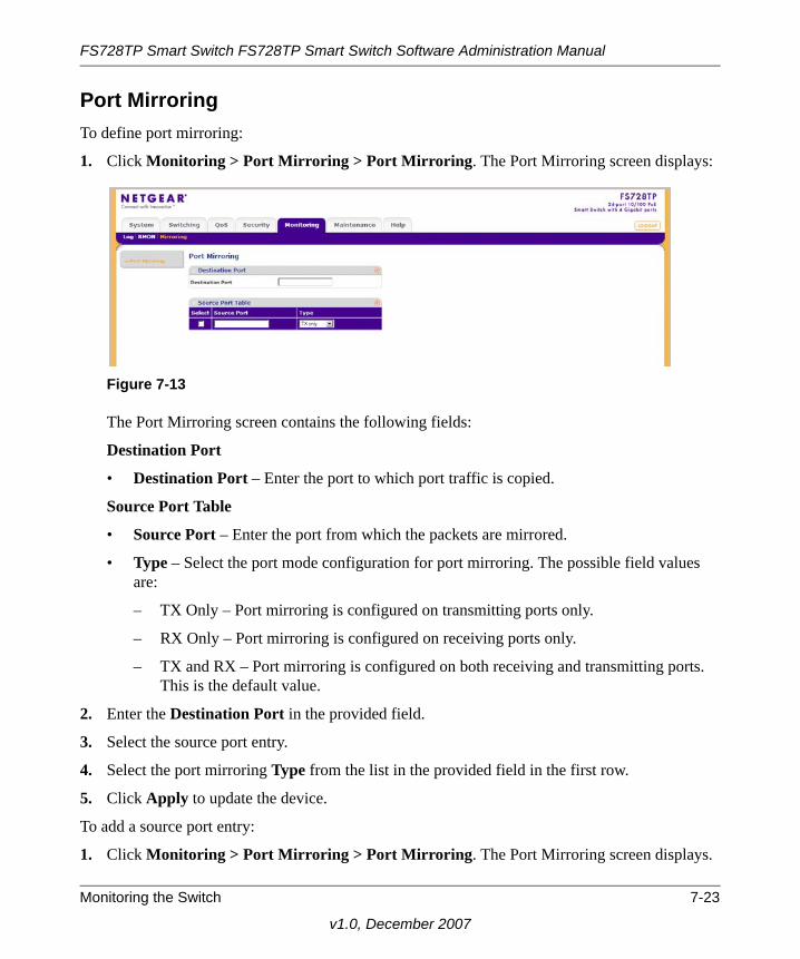
FS728TP Smart Switch FS728TP Smart Switch Software Administration Manual
Port MirroringTo define port mirroring:
1. Click Monitoring > Port Mirroring > Port Mirroring. The Port Mirroring screen displays:
The Port Mirroring screen contains the following fields:
Destination Port
• Destination Port – Enter the port to which port traffic is copied.
Source Port Table
• Source Port – Enter the port from which the packets are mirrored.
• Type – Select the port mode configuration for port mirroring. The possible field values are:
– TX Only – Port mirroring is configured on transmitting ports only.
– RX Only – Port mirroring is configured on receiving ports only.
– TX and RX – Port mirroring is configured on both receiving and transmitting ports. This is the default value.
2. Enter the Destination Port in the provided field.
3. Select the source port entry.
4. Select the port mirroring Type from the list in the provided field in the first row.
5. Click Apply to update the device.
To add a source port entry:
1. Click Monitoring > Port Mirroring > Port Mirroring. The Port Mirroring screen displays.
Figure 7-13
Monitoring the Switch 7-23
v1.0, December 2007

FS728TP Smart Switch FS728TP Smart Switch Software Administration Manual
2. Enter the Source Port in the provided field in the first row.
3. Select the port mirroring Type from the list in the provided field in the first row.
4. Click Add to update the device.
To remove a source port entry:
1. Click Monitoring > Port Mirroring > Port Mirroring. The Port Mirroring screen displays.
2. Select the source port entry.
3. Click Delete to remove the source port entry.
7-24 Monitoring the Switch
v1.0, December 2007

Chapter 8Maintenance
Using the Maintenance Options
The navigation pane at the top of the web browser interface contains a Maintenance tab that enables you to manage your FS728TP Smart Switch with features under the following main menu options:
• “Reset”
• “Upload”
• “Download”
• “File Management”
• “Troubleshooting”
The description that follows in this chapter describes configuring and managing maintenance options in the FS728TP Smart Switch.
Reset
The Reset menu contains the following options:
• “Device Reboot”
• “Factory Default”
Device RebootThe Device Reboot screen resets the device.
8-1
v1.0, December 2007

FS728TP Smart Switch FS728TP Smart Switch Software Administration Manual
To reset the device:
1. Click Maintenance > Reset > Device Reboot. The Device Reboot screen displays:
The Device Reboot screen contains the following field:
2. Check this box and click Apply below to reboot – Confirm the rebooting operation.
3. Check the confirmation box.
4. Click Apply to reset the device.
Factory DefaultThe Factory Default screen allows network managers to reset the device to the factory defaults shipped with the switch. Restoring factory defaults results in erasing the configuration file.To reset the device to the factory defaults:
1. Click Maintenance > Reset > Factory Default. The Factory Default screen displays:
The Factory Default screen contains the following field:
Figure 8-1
Figure 8-2
8-2 Maintenance
v1.0, December 2007
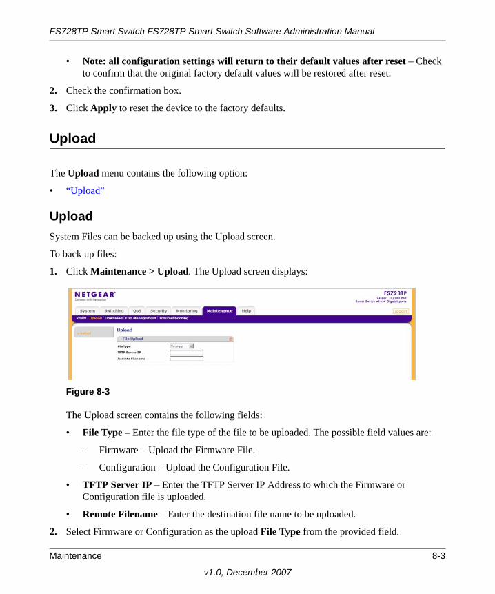
FS728TP Smart Switch FS728TP Smart Switch Software Administration Manual
• Note: all configuration settings will return to their default values after reset – Check to confirm that the original factory default values will be restored after reset.
2. Check the confirmation box.
3. Click Apply to reset the device to the factory defaults.
Upload
The Upload menu contains the following option:
• “Upload”
UploadSystem Files can be backed up using the Upload screen.
To back up files:
1. Click Maintenance > Upload. The Upload screen displays:
The Upload screen contains the following fields:
• File Type – Enter the file type of the file to be uploaded. The possible field values are:
– Firmware – Upload the Firmware File.
– Configuration – Upload the Configuration File.
• TFTP Server IP – Enter the TFTP Server IP Address to which the Firmware or Configuration file is uploaded.
• Remote Filename – Enter the destination file name to be uploaded.
2. Select Firmware or Configuration as the upload File Type from the provided field.
Figure 8-3
Maintenance 8-3
v1.0, December 2007

FS728TP Smart Switch FS728TP Smart Switch Software Administration Manual
3. Enter the TFTP Server IP address in the provided field.
4. Enter the upload Remote Filename in the provided field.
5. Click Apply to upload the file.
Download
The Download menu contains the following option:
• “Download”
DownloadSystem files can be downloaded using the Download screen.
To download system files:
1. Click Maintenance > Download. The Download screen displays:
The Download screen contains the following fields:
• File Type – Enter the file type to be downloaded. The possible field values are:
– Firmware – Download the Firmware file.
– Boot File – Download the Boot file.
– Configuration – Download the Configuration file.
• TFTP Server IP – Enter the TFTP Server IP Address from which the Firmware, Boot or Configuration file is downloaded.
Figure 8-4
8-4 Maintenance
v1.0, December 2007
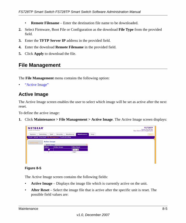
FS728TP Smart Switch FS728TP Smart Switch Software Administration Manual
• Remote Filename – Enter the destination file name to be downloaded.
2. Select Firmware, Boot File or Configuration as the download File Type from the provided field.
3. Enter the TFTP Server IP address in the provided field.
4. Enter the download Remote Filename in the provided field.
5. Click Apply to download the file.
File Management
The File Management menu contains the following option:
• “Active Image”
Active ImageThe Active Image screen enables the user to select which image will be set as active after the next reset.
To define the active image:
1. Click Maintenance > File Management > Active Image. The Active Image screen displays:
The Active Image screen contains the following fields:
• Active Image – Displays the image file which is currently active on the unit.
• After Reset – Select the image file that is active after the specific unit is reset. The possible field values are:
Figure 8-5
Maintenance 8-5
v1.0, December 2007

FS728TP Smart Switch FS728TP Smart Switch Software Administration Manual
– Image 1 – Activate Image file 1 after the device is reset.
– Image 2 – Activate Image file 2 after the device is reset.
2. Select the image file to be active in the After Reset provided field in the first row.
3. Click Apply to update the device. You must reset the device for the active image setting to take effect. See “Reset” for detailed instructions on resetting the device.
Troubleshooting
The Troubleshooting menu contains the following option:
• “Diagnostics”
DiagnosticsThe Diagnostics menu contains the following option:
• “Cable Test”
Cable TestThe Cable Test screen contains fields for performing tests on copper cables. Cable testing provides information about where errors occurred in the cable, the last time a cable test was performed, and the type of cable error that occurred. The tests use Time Domain Reflectometry (TDR) technology to test the quality and characteristics of a copper cable attached to a port. Cables up to 120 meters long can be tested. Cables are tested when the ports are in the down state, with the exception of the Approximated Cable Length test.
8-6 Maintenance
v1.0, December 2007

FS728TP Smart Switch FS728TP Smart Switch Software Administration Manual
To test cables:
1. Click Maintenance > Troubleshooting > Diagnostics > Cable Test. The Cable Test screen displays:
The Cable Test screen contains the following fields:
• Interface – Enter the port to which the cable is connected.
• Test Result – Displays the cable test results. Possible values are:
– No Cable – A cable is not connected to the port.
– Open Cable – A cable is connected on only one side.
– Short Cable – A short has occurred in the cable.
– OK – The cable passed the test.
• Cable Fault Distance – Displays the distance from the port where the cable error occurred.
• Last Update – Displays the last time the port was tested.
• Test – The test results are displayed.
Figure 8-6
Maintenance 8-7
v1.0, December 2007

FS728TP Smart Switch FS728TP Smart Switch Software Administration Manual
• Cable Length – Displays the approximate cable length. This test can only be performed when the port is up and operating at 100Mbps or 1 Gbps.
2. On the row containing the interface to be tested, click TEST to test the cable connected to the interface.
8-8 Maintenance
v1.0, December 2007
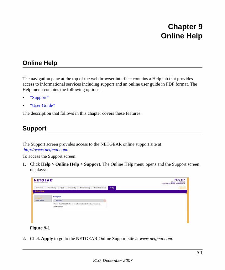
Chapter 9Online Help
Online Help
The navigation pane at the top of the web browser interface contains a Help tab that provides access to informational services including support and an online user guide in PDF format. The Help menu contains the following options:
• “Support”
• “User Guide”
The description that follows in this chapter covers these features.c
Support
The Support screen provides access to the NETGEAR online support site athttp://www.netgear.com.
To access the Support screen:
1. Click Help > Online Help > Support. The Online Help menu opens and the Support screen displays:
2. Click Apply to go to the NETGEAR Online Support site at www.netgear.com.
Figure 9-1
9-1
v1.0, December 2007

FS728TP Smart Switch FS728TP Smart Switch Software Administration Manual
User Guide
The User Guide screen provides access to the PDF format of the User Guide.
To view the User Guide screen:
1. Click Help > Online Help > User Guide. The User Guide screen displays:
2. Click Apply to open a window and display the User Guide in PDF format.
Figure 9-2
9-2 Online Help
v1.0, December 2007

Appendix ADefault Settings
This appendix provides default settings for the NETGEAR Model FS728TP Smart Switch. You can always configure the switch to default settings by using the Factory Reset function from a Web browser.
Table A-1. Default Settings
Feature FS728TPDefault Setting
Port Speed Auto-negotiation
Port Duplex Auto-negotiation
Flow Control (half duplex) Disabled
Flow Control (full duplex) Disabled
IP Configuration DHCP enabled
Password password
VLAN 802.1q based VLAN
Link Aggregation (Trunk) Disabled
Traffic Prioritization (QoS) Optimized for flow control, all ports set normal priority
A-1
v1.0, December 2007

FS728TP Smart Switch FS728TP Smart Switch Software Administration Manual
A-2 Default Settings
v1.0, December 2007

Index
AACL 17
BBandwidth Settings 5Boot File Download 4
Cchanging the password 8configuration
monitoring 1network parameters 5QoS 1security 1switch 1system settings 1
Configuration Download 4Configuration Upload 3CoS 3CPU 29
Ddefaults
IP address 8subnet mask 8
DHCP 3DHCP server 3DSCP 1Dynamic MAC Address Table 37
FFirmware Download 4
v1.0, Decem
Firmware Upload 3Flash Logs 6
Ggetting started 1
HHistory Table Page 16
IIGMP Snooping 29installing 3, 5interfaces
switch management 2Web browser 1
IP addressdefault 8
LL2 28LACP 12LAG 4Layer 2 29Link Aggregated Groups 4Link Aggregation Control Protocol 12list of RMON events 19logging into the switch 1Logs Configuration 2
Mmap CoS 7
Index-1
ber 2007

FS728TP Smart Switch Software Administration Manual
Memory Logs 4menus 2Multicast Forward All Page 35Multicast Groups 33, 34
Nnavigation menu 2network alarms 20network parameters 5NIC settings 6
Ppassword
changing 8PoE 7Port mirroring 22Port VLAN ID (PVID) 20PVID 20
QQoS 1QoS configuration 1Queue shaping 5
RRADIUS 2Remote Monitoring Statistics 9Restoring factory defaults 2
Sscheduling scheme 5security configuration 1Server Logs 7SNMP 13SNMP groups 23, 25SNMP v3 13stacking 7
STP 22subnet mask 8switch
device 7switch configuration 1switch monitoring 1system configuration 7System Logs 1system requirements 1
TTACACS+ 4TDR 6Terminal Access Controller Access Control System
(TACACS+) 4traffic queues 9Trap Filter 30, 31
Uupgrading the firmware 9utilities
Smartwizard Discovery 2switch maintenance 1system settings 1
Vview 7VLAN 14, 16VLAN Membership 17VLANs 14VPT 1
WWeb access 7, 1
Index-2
v1.0, December 2007