from aircraft gas turbine engines - defense … · repir1lt n.faa-rd-11-111,3 the c~ontrol olf...
TRANSCRIPT

Repir1lt N.FAA-RD-11-111,3
THE C~ONTROL OlF OX!IDES AN NTOGN EMISIONS
FROM AIRCRAFT GAS TURBINE ENGINES
Volume 3: The Flow Model
Ronald S. Fletcher Richard D. SiegelNorthern Resdarch and Engineeriitg Corporation
219 Vassar StreetCambridge, Massachusetts 02139
~101TAX
SEEME 1911d a 7j~ 02
C,Availability is o.nlimited. Dcocument may bereleased to the National Technical InformationService, Springfield, Virginia 22151, for saleto the public.
Prepared forIx~ NATlCIMAL TECHNICAL
INFORMATION SERVICESV1 22151
DEPARTMENT OF TRANSPORTATION ENVIRQNMENIA RTCiNAECFEDERAL AVIATION. ADMINISTRATION Office of Air Programs
SyStelus Resear,1& DERItInpent Service ANN ARBOR, MICH. 48105Wasfitgtc, D.C. 20521If

I
The contents of this report reflect the views ofthe Northern Research and Engineering Corporationwhich is responsible for the facts and the accuracyof the data presented herein. The contents do notnecessarily reflect the official views or policyof the Department of Transportation or the Environ-mental Protection Agency. This report does notconstitute a standard, specification or regulation.
iJim
Soo'

TECHNICAL REPORT STANDARD TITLE PAGE1. Report No. j2. Cino~wnt~~it Accession No. j3. R.cipi~pls Co.oieg No.
t FAA-RD-71-11i-3_______________A. Tinle ofti Sivbtlile 1 5. Rep~ri Date
THE CONTROL OF OXIDES OF NITROGEN IDecember. 19715EMISSIONS FROM AIRCRAFT GAS TURBINE ENGINES 6. Perfors*np Otgo..itaoon Code
VOLUME 3: T11E FLOW MODEL7. A,~e~ Ronald S. Fletcher 8I ~ ~Richard D. Siegel 16-
9. Porformini Orrgmithlofi Nc_-A and Address 10. Work uhit No.Northern Research and Engineering Corporation 11 __________or _________No.PtI 219 Vassar Street ~Cnf~?0 rn oCambridge, Massazhusetts 02139 1 DOT FA70OWA-2428
13 Typw of Report and Period Covered
12 oosr*9Iecy No" wrvi Aiiress1Department of Transportation Envirornmental Protection Fil eport:Federal Aviation Administra- Agency j e 90Dcme,17
__tion Office of Air Programs j14- Spnsoring Apsincy Code
Washington, D. C. 20590 Ann Arbor, Michigan 48105i
Z ~ 15. SwpIenimntowy Noes.
I The objective of this study was to develop criteria for use in the designk ~ of aircraft gas turbine rombus 'tion chambers to minimize nitrogen oxi de emissions.
e jThe approach adopted involved the development of a mathematical model of NOx e~missi;onjfrom. aircraft engine ..anbustors;, a ptrametric analysis, using the model, to determinethe sensitivit- -;' iq Ox emciissions to-variations of model parameters and engine desigrvariables;, ev'aiuat'ion of crit'icai miodel'parameters by means of experimeantal measure-
M; ments; and the incorporation of the model into combustor design ineth.~s to provideZý guidelines for mih'imizing N~x emission while maintaini ng other perform~ance and emis-
sion characteristics. The results of the study end the NOx emission control criteriaX-ftare des~ribed in VoU~ie I (FAA-RD-71-Mi-0). Volume 2 (cAA-RD-71-lll-2) describes
the nitric oxide fic--ation process and a cornputer program (NCXRAT) for calculatingthermodyna.mic data. The program is based upon a six-reaction model of NO formation.Volume 3 (FAA4-RD-7,1-lll-3)'describes combustion and flow prc-esses in gas turbinecombustors and a computer program (GASNOX) for calculating gas properties and NOconcentrations throughout a combustor. This progarm is based upon a three-zone,heterogeneous model of gas turbine com-t'istor operation. Program GASNOX is used wi th.input data from Program. NOXRAT to calcualate NO emission rates.
jAir Pollution Gas Turbine Availability is unlim.ited. Document mayNitrogen Oxides Theoretical Model be released to the National Technicalnitric Oxide Experimental M1easurementl Information Service, Springfield, Virginia1Aircraft uesian Criteria 22151, for sale to the public.
19. SeCvnity Clssril. (of Ithis repeuil 23. Secrimy 0"841z. (of ta Peo.-) 21~. Re. of P&;** 22 Ptice
UNCIASS37ED= U1NCIASS=3LDI
Form DOT F 1700.7 (s.S*) i3 L 9 r
mk
L
The study reported hcre was carried out under the technical
direction of Dr. D. M. Dix with Dr. Ronald S. Fletcher assuming project
Sresponsibilities. Other participants in the program were Dr. R. D. Siegel,
Dr. E. K. Bastress, and Mr. R. J. Murad; Professors J. B. Heywood, A. H.
Lefebvre, and Mr. E. R. Norster served in a consulting capacity during the
course of the study.
This study was sponsored in part by the Federal Aviation Admini-Sstration and the Environmental Protection Agency under Contract No.
DOT FAO-OWA-2428. Technical monitoring of the program was conducted by
Mr. William T. Westfield (FAA) and Mr. George D. Kittredge (EPA).
i-t

CONTENTS
PageI. INTRODUCTION . . . . . . . . . . . . . . . . . . . . . . . i
2. THE FLOW MODE-L ...................... 22.1 The Generalized Conservation Equationr. .... ....... 22.2 The Distribution Function .......... .............. 42.3 Application to the Primary Zone .... ........... .
2.4 Application to the Intermediate Zone ........... . .. b2.5 Application to the Dilution Zone ... ......... ...2.6 Computational Procedure ...... .............. . .. i
2.6.1 Required Input ...... ................ . ...2.6.2 Preliminary Calculations .... ........... ... 122.6.3 Prediction Procedure ........ ............. i3
3- PROGRAM GASNOX ...... ........... ....... ......... 163.1 Introduction ....... ... .................... ... 16
3.!.1 Program Function and Capabilities .... ..... 163.1.2 Report Arrangement ..... .............. ... 17
3.2 Input Data ............ ..................... ... 173.2.1 General Description .. ............ 173.2.2 Detailed Description of Input Data .... ..... 193.2.3 Discussion of Input Data .... ........... ... 233.2.4 Description of Sample Case Input ......... ... 23
3.3 Output Data .......... ..................... ... 233.3.1 Normal Output ......... ................ ... 243.3.2 Error Messages- and Additional Output . . . 293.3.3 Description of Sample Case Output ... ...... 32
3.4 Miscella~neous Operational Information ........... ... 32
3.5 Data input Sheet ............ .................. 333.6 Sample Case Output ........... ................. 35
4. REFERENCES ................. ....................... 43
5. FIGURES ....... ........... ......................... .44
6. NOMENCLATURE . ................ ...................... 49
7. APPENDICES ............... ........................ 51Appendix I - Over-All Program Logic .... ....... 52Appendix :1 - Con.non Fortran Nomenclature ........ 54Appendix III - Main Routine GASNOX ............ ... 62
- Appendix IV - Subroutine PRI MRY ............... 70Appendix V - Subroutine ZINTER .............. ... 78Appencix VI - Subroutine DILUTE .... ......... ... 99Appendix VII - Subroutine PRCALC .............. .. 112Appendix Vill - Subroutine PRRAT. .............. .. 123Appendix IX - Subroutine MINT. ............. .. 126Appendix X - Subroutine CALCBC ............ . 131Appendix XI - Subroutine CHECKK ............... 134EV

CONTENijS (CCGRsIIJuE&,)
fApcendix X'I - Subrouti..e Jkot...... .. .. .. . . ... eArppen-eix wI! - Sub~routine DERIV .. .. .. . .. .1Apper-dix AMV - Subrouzflr MhASS . ......... 146Appendix XV -Subrout~ne PRIiNTS ....
Appendix AM - Met-Soe o' Clalculation of AirDistrIll:ii~or Characteriscics . . . . 6
vi

LIST OF FIGLIESPage
I ASS,,Et FLOW ANI DISTRIBUTION F'TEP.TiROUGHOUT CO.BUST:-?R L•NEU R"
Z pa,'MARy ZONE. COMBUSTION EFrCECYC,.-:[A•H. . .
47
3SC.HEKtA-iC REPRESENTATION' OF NUSTCUR
it .. . . .48
; A~ ?40MDULAR TREE DIAG.A..
Ir0
,,,t

1. INTRODUCTION
Volume I of this report carries a full description of the complete
program but omits mathematical details of the model developed to
predict the nitric oxide (NOx) emissions from aircraft ghs turbine
combustors and aiso the details of two computer programs developed
as part of the study for obtaining predictions from the ,-del. It
is the purpose of Volumes 2 end 3 of the report to present full
descriptions of both the model and the computer programs.
It is convenient to consider the model in two parts, one part
being concerned with the NOx formation profess and the other with
modeling the flow behavior within gas turbine combustors. The
convenience arises not only due to the basic difference ii. the studies
of these two parts, but also due to the fact that a separate co~npu-
ter prooram has been developed for each part. This approach has been
adopted ;n the interest5 of ecenom~y of computation as calculation of
the :..cessary data for the determination of the NOx formation Drocess
requires appreciable computer time but the data once collected can,
of course, be applied to any ccombustion calculation with the same
reference conditions (in this case, combustor inlet conditions) of
pressure and temperature. The computer prog.-3m developed for this
task has the name NOXRAT, anj its function is to compute the rate
terms of the NOx formation process and all relevant ther-modynamic data
:or a series of fuel-to-air ratios with a co-iamn reference state.
Volume 2 of this report is solely concerned with the nitric
oxide formation process. It presents a mathematical description of
the program NOXRAI and also includes : section which is essentially
a user's manual for the program. Volume 3 produces the same details
for the flow mc•iel developed to describe the f 1- conditions in agas turbine combustor. The corresponding computer program is named
GJ.SIOX and it is so arranged that the rate terms and ail relevant
therm-odyna-mic data computed in NOXRUAT are punched onto a deck of =om-
purer cards which serves as inruc data to the main program GASNOX.
The ob•ective of this volume of the report, therefore, is to
present the th-ry behind the flow audel and details of the computer
progra:n developed for its application.

2
2. THE FLOW MODEL
Calculations based upon the reaclicn scheme described in Volume
2 clearly sho that for significant concentrations of nitric oxide
to be formed during the short ti.ne it takes the gases to pass through.
a aircraft gas turbine engine, the temperature must exceed 2000 deg
K. Such high temperatures only e-xist within the conbustor, and only
thu-. for a limited time, so clearly, nitr:c oxide concentrations in
the exhausts of aircraft engines are solely dependent upon the fisw
behavior and tic .hemical processes occurrir.g within the cnb'pston
"chamber and it !; these features that must be adequately representedSin the model.The first task, tnerefore, is to select Z method of modeling the
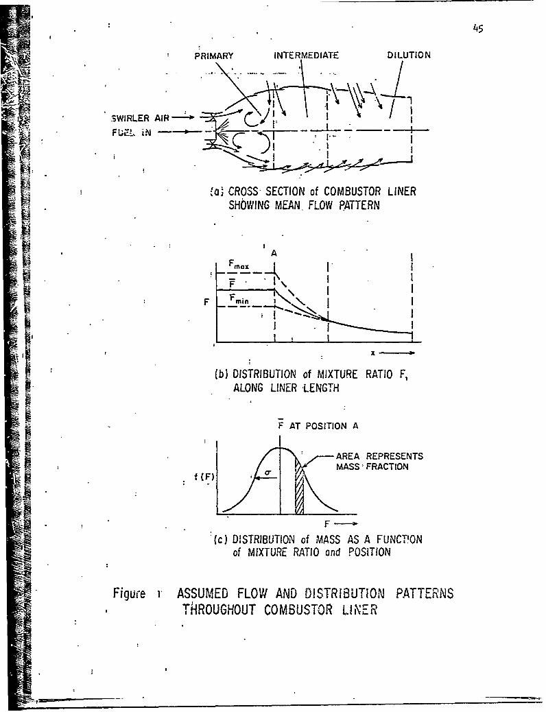
flow processes in the gas turbine combustor. Such cocmbustors are
conventionally divided into three zones as shown in Figure ia. The
distinction between these zones is discussed qualitatively in Volume
1, Section 3, but in the next section these dislinctions are ouantified.
Firstly, the basic conservation equa-tions are derived for the general-
i-ed case of an inhomogeneous, reacting gas mixture of the type that
occurs in a gas tturbine cwnbustor. These equations are then rcdiced
to conditions applicable to the three c usto,- zones, the primary,
intermediate and dilution zones, which are of interest to this study,
and finally, they are used to demonstrate how tVe nitric oxide levels
may be calculated for cach zone.
2.1 THE GENERALIZED CONSERVATIflN EQU..iONS
A control volume will bz considered to contain procucts of con-
stant fuel-to-total mass ratio, F. which will be termed the'mixture
ratio. (The constancy of F is taken as it has partic7,iar utility in
this study insofar as that it minimizes the nuiaiber of calculation- -or
the equilibrium conditions necessary to determine local nitric oride
reaction rates.) The volume is as snown below:

___---"# -- ---
Ld [NO I� C' [W02 X
where, & = mass flow in interval SFabeut
LN Oilmass frzztion of nitric oxide
e - fl8• j€),fractional mass flow of unburned 'uel
L a inass flow per unit length of fuel ratio P1, with .nass
fra~ionof NO = (No] which enters ýzhe volume due to mixingI r- -tj
Iwss fllow per unit length, with mass fraction of BO 0 3OJ
whiclh I-vis the volte- dte to mix;ng
SA = crc.s sectional area of element
r rate of formation of NO per unit volume by chemical reaction
The corservation equations become,
forK , d- ( ,,,)- MA + m, A-I
mass, .. j S A-2
hburnedfuel, IM - a A-3
un~*:;e fr_!~~ specified A-4.
IIn th~e AImit asci)Cter.-s 20 z~ero3, these equations take the form,
:d LnrV + A-Ia
dF 3 CI
d; F rT\

4
-F• I) A-3a
R A-4a
dXNCIFf lfd
2.2 THE DISTRIBUTION FUNCTION
The cor,'rol volume considered above is only concerned with an
ele.nt of mass &with a mixture ratio SF abeut F it was proposed to
represent the distribution of mass about mixture r3tio by a normal distri-
bution function of the ;1orm,
* C A-5
The parameter in statistical terms, is called the standard deviat;un and
represents the degree of distribution of F about the mean value F.
"". is termed the normalizing factor and for the purpose of this study"
is defined by the eprisson that,
_Sn 2s = (i -E) A-6
The value of F is the ratio of the total fuel burned to the total mass flow.
Clearly both C_ and F will be a function of the axial position in the combustor
as they are computed from Equations A-2 end A-3.
A normai distribution has been selected as it is known to fit tne
soray characteriscics of the type of fuel injectors used in 9as turbine con-
bustors and it provides a coavenient way of describing the mixing process, by
- specification of the relationship 6 ( The value of &m-, the mass flow
in interval SP about F1 can al;o be evaluated functionally by the equation f Dri,
j £~'•/s JF A-7SF•-S 2

5
and so the whole flow field can be readily represented by a series of discrete
elements of constant, but different, mixture ratios.
2.3 APPLICATION TO THE PRIMMY ZONE
The model of the flow behavi'or described previously assumes that
no mixing takes place in the primary zone after :he specified distribution
of mass mixtures ratios is attained. Thus, referring to the control volume
above, S S-o
and furthet, it is also assumed that only a certain fraction A of the total
fuel entering the zone is burn.d a--d that this fraction burns instantaneously.
so equation (A-I) reduces to,
C'~ icJ ( & C1 A-B
or, IN 01 A-0
or alternatively. 0k= ) LA-10
where is the density of the elemrnnt and t is the time ;t takes to pass
through the prim-ay zone. It is taken that > , the mean density it. -e
primary zcone where,
i- - A-Il
The nature ot the normal distribution "unction is that f(F)dF oniy tendsto zero as F tends to±oO . Negative rShave no physicalosignificanceso a constraint is imposed upon the function tha' ,<i-242F thus pre-serving the useful feature of symmetry about F. ,i fact, if 6 is lessthan4-/Z, this constraint modifies the function to ,inly a very smallextent as it can be shown that the integral is gre.ater than 99.7 percent Of ,h~at over the range:1* • PracticallIy, a range of 6'f rorm 0 to F/:&
will represent a wile range in distribution characteristics. it shouldalso be noted that C andmare simply related.!y the equation C.r=f7-TP•
if th~e limits are expr--ssed frorn..z¢=wP.

6
but the value of , cannot be so simply expressed for the case of a
completely-stirred reactor. Theoretical considerations dictate
(see Ref 1) that various fractions of the mass flowbM have differ-
ent residence times accotding to the function,
- -A-12
where 3 is the mean residence timae and is equal to the ratio of
(VWR/I ) and where is the volume of the primary zone. Therelationship, ,Lu
F (i
11 ~rj ~&~~~)d6A-I13
then defines a fraction n of SMq which has a residence time
within the range d& about R . It is therefore necessary to solve
Equations A-10 and A-13 to compute a series of • values corre-
spondirng to the [NO&• concentrations over the range of +_ from
zero to infinity. The mean nitric oxide concentration at the exit
of the zone for an element of mixturz ratio F , F , is then
calculated from,
RE A- 14
and the process repeated for all elements over the mixture range of
interest.
Finally, an over-all mass .nean average nitric oxide concentra-
tion for all products leavino the primary zone can then be computed
by summing all products [NO Fm and dividing by the total mass
flow rate through the primary zone.
2.4 APPLICATION TO THE INTERMEDIATE ZONE
In the intermediate zone, mixing is assumed to occur over the
R length of the zone L , such that at the exit it is uniformly mixed.
We postulate that mixing is characterized by the expression,

7
~~-.c~Nl A/ll' A- 15c
where cj is the prescribed deviation for the primary zone, A is a
model constant and X is the axial distance from the primary zone
exit. The distribution of the mixture ratio F is therefore known
at every point, i.e., ISM= V(v,X) SX is prescribed by
Equations A-5, A-6, and A-15. The problem therefore reduces to
determining S§11/, S; , and F'fron Equations A-2 and A-4 and to
making certain assumpt;ons about the mixing process, as [NOIJ and
[NO] * must be determined in order that Equation A-i can be
solved for [N0] as a function of F and X .
We will postulate that ail mixing occurs at conditions corre-
sponding to entry conditions into the control volume so,
41 = ;r
and also that, 5r)" -- A-16
which is to say that the flow out of the elementa! control volume,
due to mixing, is proportional to the amount flowing into the control
volume. Clearly 1( must have units of i/length and the physical
interpretation of K can best be thought of in terms of the ratio,
CN ,of the mass flow rate leaving the element over the length of
the intermediate zone to the mass flow rate within the element. If
this latter mass flow rate is constant, then clearly
or, m /XL
It will be assumed that the value of 1< is known. Equatiorn A-2 then
yields,
7ýXx-• A-17
where it is to be noted that the restrictions,

8
K 4
A-18
"must be satisfied for the. model to be valid.
The gases flowing into the control volume as a result of mixing,
SIM, will originate from two sources: firstly, from the mixing of
gases aIready within the conbustor liner, which we will denote as
!} •and secondly by the mixing action of the diluent air with
previously mixed gases, which we will call .. Clearly,
'I A-19
and we will postulate xhat,
A-20
that is, that the ar,..unt of diluent air entering Zhe control volume
is in proportion to the total mass flow rate in the volume. The
problem is then defined in terms of Sii', SI"D V and F' as,S , A21
from Equations A-17, A-19, and A-20, and also as a consequence of
Equation A-3. F 3
""•' S,) A-22
The value of [NO] must now be calculated. Clearly, the total
nitric oxide mass which leaves all the elements by mixing must also
return via the mixing process to preserve conservation of the specie.
The following relationship is assumed to apply, therefore, that
(~Nor)A-230
The value of R , the rate of burning of the unburned fuel which
leaves the primary zone (see Equation A-4), is now all that is neces-
sary to calculate NO concentrations throughout the intermediate zone.

9
It is postulated thac this rate of burning is controlled by the
mixing process, so in keeping with the Equation A-15, the following
is assumed, F Ar EC - -A4
where A and A are model constants, E=, is the 'ractional mass of2 3*
unburned fuel entering the intermediate zone and is given by
Smay therefore be computed, as by definition (see Equation A-4),
it is equal to _ . Thus the problem is defined as,
Fr is known from Equations A-19 and A-21
S01" is known from Equation A-16
ENO01 is known from Equation A-23
[No]'is equal to [jo 0
and %M -- 1,' kF;Yx F, is given by the specified di3tribution
function.
if these values are subc*.ituted into the conservation equation
for nitric oxide (Equation A-2) then it can be shown that,
5S.J. Ax
IR A-26
where V is the velocity and,
IM C3ENOJA-27
This equation has to be evaluated in a stepwise manier in order to
calculate the relationship N 0 q]S in the intermediate
zone. It Is then a simple matter to compute an over-all mass average
nitric oxide concentration at each axial station from,
Another way to express these rj.lationships is as:
00 0 s)(• ,,v,,-./ý•

10
.• • _ vA-28
and so complete the computation.
2.5 APPLICATION TO THE DILUTION ZONE
In the dilution zone all gases are assumed to perfectly mix to
a mean mixture ratio. All fuel is assumed to have been burned
previously in the combustor and only diluent air enters the zone.
For this case therefore, one cannot consider a control volume of
constant mixture ratio F , as was done at the introduction to this
section, asF must change with axial distance due to the added air
flow. For the special case of the assumptions made above, this
change may be accoated for by modifying only Equation A-3 of the
conservation equations so that this dependency of F with X is
properly accounted for.
The conservation Equations A-I through A-4, can be shown to be
~ given by,
IL SM) -
as the above assumptions imply that,
and,
The conservation equation for nitric oxide can be rtduced to the form,
END]~ic~ aX4c 4- = A-29X -
-which predicts directly, the mean average nitric oxide concentration
at the new axial position. This process can be repeated in a step-
wise manner tc the end of the combustion chamber and hence the nitric
oxide concentration at the exit plane may be predicted.

2.6 COMPUTATIONAL PROCEDURE
A summary is presented below of the computational procedure
necessary to combine the flow model and the chemical reaction scheme
presented in Volume 2 in order to predict nitric oxi,** emissions fron
aircraft turbine engines.
2.6.1 Required Inout
The following input is requ:red in order for the computation
to proceed:
a- Chemical Reaction Szheme
1. A means of evaluating the adiabatic flame temperature,I density and composition of the equilibrium products for
the combustion of hydrocarbo.ns in air. Program NOXRAT
described in Volume 2 serves the purpose.2. Values of the rate contaat' V.to k-
WR Fuel properties in terms ofC1ij ratio.
b. Combustor Dimensions
These should be expressed in such a way as to allow calculation
of,
1. Volume of the primary zone.
M 2. Area of the intermediate and dilution zones as a!j function of distanceXC.
c CombTustor Operating Conditions
W The following should be expressed as a function of aircraft
operating mode,
1. Cocbustor inlet temperature and pressure.
Ii2. Total fuel flow rate.
3. Air-flow conditions in terms of the fraction entering1 the primary zone and the rate of addition at the walls as
as it varies with axial position along the combustor.
d. Other Inputs to be Specified1 I " The functions,
d', T(K) (see Equation A 15)
and,&z e 60 (see Equation A-24)
!:1I
12
2. The value of 1K, or CN , which defines the fraction
of gases that leave an element of constant mixture
ratio F due to mixing (see Equation A-16)
2.6.2 Preliminary Calculations
Two preliminary calculations must be performed before the compu-
tation of NO concentration levels can be undertaken.
These involve,
a. The determination of i value for • , the fraction of total
fuel entering the primary zone that is burned in the zone.
b. A consideration of the mixing characteristics of the cool-
ing air that enters the combustor liner from the walls of
the intermediate and dilution zones. The bulk of such flowt normally enters perpendicular to the direction of the main-
stream product flow and has then to be deflected and en-
trained before it can enter the fully developed mixing
processes. This action must require a finite time (i.e.,
distance) to occur, and its effect upon the nitric oxide
formation process !,as to be considered.
Combustion Efficiency
A correlation does exist to relate primary zone combustor effi-
ciency to the fuel loading parameter inf/VpP2 . The correlation is
given in Reference 2 and is reproduced in Figure 2. There is sig-
nificant scatter in the data points used to obtain the correlation
and the.values of the primary zone efficiency determined using the
correlation can be expected to have error limits of approximately
+ 20 per cent of the indicated value.
Air Distribution Characteristics
In the calculation of the rate of diluent air addition to the
intermediate and dilution zones, some provision must be made for the
time (hence distance) necessary for the dilution gases to mix into
the mainstream flow. This mixing laq could conceivably affect NO
13
emissions signilicantl.t under certair circumstances a: it controls
the rate of temperattire change at positions downstream of the primary
zone exit. A simple method was developed to take some account of this
effect and is described fully in Appendix XVI. The method is con-
sistent with the mixing assumptions used to develop the model for theintermediate zone of the combustor and at the same time, it determines
the fraction of the air that enters the primary zone.
2.6.3 Prediction Procedure
in the interests of economy of use of Program NOXRAT which de-termines the flame temperatures and concentrations of the C-H-O-Nspecies at equilibrium conditions, hence the NO formition rates, the
distribution function of mixture ratio F , versus mass fraction
(Equation A-5), is considered as a series of elements of differing
'ýF. The :irst task in each step is to calculate the mass fraction
in each element from the equation,
for the prescribed conditions and thus relate ý) to FI The •F increments are selected, then the adiabatic flame tem-
peraturesT7 , the density and the corresponding equilibrium con-
centrations of the species N, N2 0, NO, C2 , 0, OH, and NO are determined
from Program NOXRAT for each F. These specie concentrations are then
used to determine the values of R1 , R6, K1 , and K2 (for each F ) whichare needed to compute the race of nitric oxide formed by chemical
reaction and the calculation then proceeds as follows.
Primary Zone
a. The specified value of • , the fraction of fuel burned in
the primary zone, is used to compute S o can then
be determined for all F values oVer the range of interest

14
b. The value of thu ;,ean r:s.idence time ýT is determined
from Equation A-12.
C. Nizric exide ccnrentratlon- at the primary zone exit can
BE ,; then be ca-iputed for each F and for the prescribec, rev--
dernee time distribution by solvino in an iterative manner
WK the relationsh.p,
t id. Finally the mass average nitric oxide concentration is com-
puted for all gases leaving the primary zone from the re-
latlonship, F2F
FNoI
Intermediate Zone
The calculation procedure for this zone, for each incremental
step in the axial direction, is essentially identical to that for the
primary, except for the necessity to coanpute a change in NO concen-
tration due to the mixing process. The procedure is as follows:
a. For X-X+AYX , new values of 0m are computed at each E
from Equation A-5.
b. The value of rNO1' , tie concentration of nitric oxide in the
gases entering the control volume by mixing over the step
is camputed according to Equation A-23.
c. The nitric oxide -oz centration at position X+AX is then
computed for each mixture ratio F by integration of Equa-
tion A-26.
d. Finally :i-e new ffass average nitric oxide concentration isI computed as for Step d above.
These steps are repeated to the end of the intermediate zone.
Di h2!ion Zone
The results of the intermediate zone calculation serve as input
to the dilution zone. At this stage all elem-ents in the combustor are
I-

of equal composition an:; tenperature, and dilution proceeds by the
addition of pure air and so .-ne can use the relationship (see Equation
A-29) that, X4dX F•rd
This: can be integrated in a stepwise manner with respect toX by
interpolation of the nitric oxide rate data at each step to determine
the nitric oxije concentration conditions at the correspondingF value.
The nitric oxide formation rate quickly reduces in this zone as
the temperature decreases rapidly.

16
3. -PROGRAM GASNOX
3.1 iNTRODUCTION
3.1.1 Program Function and Capabilities
Progrem GASNOX is a digital computer program written in Fortran
IV language for use with i.ne CDC 6600 camptting system. The program
has been developed for the purpose of predicting the nitric oxide
emission level fro. an aircraft gas tucbine combustor. Based on a
given set of combustor dimensions, operating conditions, kinetic rate
constants, thermodynamic properties, equilibrium compositions, and a
primary zone mixing parameter, the program will compute nitric oxide
concentrations as a function of axial position in annular and cananpular
combus tors.
The analytical proceJures on which the computer program is based
have been discussed in Section 2 of this volume and in Reference 3.
Briefly the model considers a c~mbustor to consist of three zones:
primar intermediate, ano dilution. The primary zone is modeled as
a partially stirred reactor with the variation of gas composition,
temperature, and residence time occurring within the zone taken into
account statistically. The program predicts oniy the gross features
of the flow at the zone exit. The intermediate zone represents a
transition between the primary and dilution zones. Here mixing occurs
between the heterogeneous products from the primary zone and the
entering cooling air. The program predicts the gross features of the
flow as a function of axial position in this zone. In the dilution
zone, the flow is uni-dimensional w.'th the gases uniformly mixed
across each cross section. Only the mean mixture ratio is considered,
and this only changes as the remaicing compressor air is mixed into
the combustor. The procedures incorporated into the program havc been
found to be quite acceptable in terms of accuracy and calculation
efficiency.

17
3.1.7 Report Arrangement;
The main body of-ihe report begins with a section in which the
input data necessary for the solution of any -:s4 are described in
detail; this includes instruo-ions for preparing and supplying these
data to the program and a sample case in the appropriate format. The
next section contains a discussion nf the various types o0 output
Sdata obtained.from the program and also of the output data from the
sample case. A description of the error messages printed by the
program is also included. Following that is a section containing
miscellaneous information regarding:the operation of the program with
the COC 6600 compufing system.
The first appendix consists of.a general discussion of the over-
all logic structure of the program. Tha next appendix gives the
Fortran nomenclature for the variables in the COMMON blocks of the
program. The remaining appendices except the last provide detailed
descriptions of the various components (main routine and subroutines)
which make up the over-all program, one appendix for each component.
The appendix for each new subroutine contdins • presentation of the
input and output variables, an internal Fortran nomenclature, a de-
scription of the step-by-step calculation procedure, and a Fortran
listing of the subroutine. The last appendix contains a discussion of
the method of calculation of the air distribution characteristics.
3.2 INPUT DATA
3.2.1 Genera! Description
j Program GASNOX requires tne following input data in order to
determine the nitric oxide emission level from an aircraft gas
turbine engine.
a. Combustor Dimensions
I. V - Volume of tie primary zbne
2. XL - I.ength of the intermediate zone (from the
exlt of the primary)
I
I:

18
3 XEND - Distance fro, the primary zone exit to
the exit from the cc-bustor liner
•. RX - Radius of liner at position X for canannular
configuration
5. R!RX - Inner and outer radii of liner at position
X for annular confguratioi:
b, Conbustor Operating ConditionsI 1. T - Inlet temperature
2. P - Operating pressure
3. •p - Mass mean equivalence ratio in the primary
zone (before fuel burns)
4. @ - Fraction of fuel entering the primary zone
which burns in the zone
5; Erat - Variable for altering p parametrically
yet maintaining constant the over-all
air-to-fuel ratio in the combustor
6. (Ma) - Total mass per cent of air mixed with the
Sproduct stream at positioh1 X in the liner
7. MA - Total mass of air fed into the combustor
linerIi 8. - Mean primary zone residence timej(applies
only if Vp is set equal to zero)
c. Mixing Parameter for the Primary Zone
1. S - Degree of mixedness in the primary zone
(where i in the distribution function0
is given by - = S (P;)
d. Kinetic Constants for each Mixture Ratio Element
a1 R - Forward reaction rate constant for the
Sfirst reaction (see Section 2 , Volume 2
or Ref 3)
2. R6 - Forward react;on rate constant for the
sixth reaction (see Section 2,. Volume 2
or Ref 3)

19
3. K] - Ratio of forward reaction rate constants
(see Section 2, Volume 2 or Ref 3)
4. K - Ratio of forward reaction rate constants
(see Section 2, Volume 2 or Ref 3)
e. Thermodynamic Properties for each Mixture Ratio Element
1. P - Density of the combustion products
2. Tf - Adiabatic flame temperature of the com-
bustior products.
f. Equilibrium Compcsitions for each Mixture Ratio Element
1.. (NO)e - Nitric oxide equilibrium mole fraction
S2. (C)0 - Carbon monoxide equilibrium mole fraction
3. (Cs) )e- Solid carbon equilibrium mole fraction
4. (CH 2 )e - Unburned hydrocarbons (exclusive of CO
and C(, ) equilibrium mole fraction.
The input data is re3d in three categcries: 1) the kinetic,
thermodynamic, and equilibrium data and the combustor inlet temperature
and pressure; 2) the combustor airflow distribution and radius versus
axial position; and 3) the remaining combustor dimensions, operating.
conditions, and the primary zone mixing parameter. With this structure
there may be several sets of data in a given computer run. Figure 3
is a schematic representation of the data input structure.
3.2.2 Detailed Description of InDut Data
The information required to prepare the input data for a case
is furnished in the table given below. This information contains
a description of each input item as well as a description of the
form .n which these items are written on input data sheets. The
descriptions of the input items refer frequently to several points,
relevant to the selection of input vaijes, which are discutsed in
the following subsection. The discussions of these points
provide additional detailed information useful in preparing the input
data for any case.
The first input item read by Program GASNOX ;s the integer variable
IDATA which identifies the number of sets of data in category 1. This
input is then followed by the first set of category I data (see point a).

20
S"put Type of FortranLine Location Item Number Symbol Description
1 1-6 Int IDATA Number of sets of data incategory I
1-72 A SET(1) Descriptive data identifying
atomic composition of fuel andthe turbine inlet temperature
3 i-14 A SET(1) Descriptive data of units ofcombustor inlet pressure
3 15-29 P FP PPP Combustor inlet pressure (atm)
3 30-51 A SET(i) Descriptive data of set ofkinetic constants used incalculation (see Volume 1,Table 2; descriptive data ofkS
3 52-66 k FP EKS Fuel-to-air mass ratio ats stoichiometric conditions
4 1-12 F. FP FF(I) Mixture ratio of an element
4 13-24 •. FP PHI(I) Equivalence ratio of an element
4 25-36 i FP RHO(l) Density of combustion 3 productsfor an element (gm/cm)
4 37-43 T. FP ATIT(1) Adiabatic flame temperaturefor an element (deg K)
4 49-60 (NO.) FP BCON6(1) Equilibrium mole fraction of49Oe NO for an element
1 4 61-72 (CO.)e FP BCON2(I) Equilibrium mole fraction of
CO for an element
5 1-12 (Cs) e FP BCON]() Equilibrium mole fraction ofC(s) for an element
5 13-24 (CH2.) FP CH2() Equilibrium mole fraction ofi e unburned hydrocarbons exclusive
of C(s) and CO for an element
5 25-36 (R1). FP RI(1) Forward reaction rate for thefirst kinetic reaction (seeSection 2, Volume 2 or Ref 3)(gm-mole/cm3 -sec) for an element

21
UInput Type of FortranLine Location Item Number Symbol Description
5 37-48 (R 6)i FP R6(lW Forward reaction rate for thesixth kinetic reaction (see
Section 2 , Volume 2"or' Ref 3)
(gm-mole/cm3-sec) for an element
5 49-60 (K1). FP EKI1(!) Ratio of forward reaction rateconstants (see Sect-on 2 , Volume2 or Ref 3) for an element
5 61-72 (K2). FP EK2(I) Ratio of forward reaction rateconstants (see Section 2, Volume2or Ref 3) for an element
Lines 4-5 are repeated for each of the 35 discrete mixture ratio
elements specified in the distribution function. At the conclusion
of this data, the integer variable KASE is read. KASE identifies thenumber of sets of data in category 2 that follow for the given set
of data in category 1.
Input Type of Fortran
Line Location Item Number Symbol Description
74 1-6 Int KASE Number of sets of data incategory 2
75 1-12 X FP AXX(J) Axial position in the com-bustor (in)
75 13-24 (Max) FP APR (J) Per cent of total mass of air-
X % flow in combustor liner atposition X (cumulative)
75 25-36 RX FP ARR(J) Radius of liner at positionX; applies only for canannularconfiguration (in) (see pointb)
75 37-48 Rx FP ANR(J) Inner radius of liner at
! position X; applies only for
annular configuration (in)(see point b)
75 49-60 RX FP ANNR (J) Outer radius of liner a,position X; applies only forannular configuration (in)(see pointb )

22
Line 75 is repeated for each of 11 axial positions in the
combustor. The first axial position must be taken as X -0; that
is, at the exit of the combastor primary zone.
There may be as many sets of data in category 3 for eacn set
of data in category 2 as the user desires. The number of these data
sets is read as the variable IN, on line 86.
1nPut Type of FortranLjj Location Item dumber- Symbol Description86 1-6 tnt IN Number of sets of data in
category 3
Following the data on line 86 is tne data of category 3.
lnou•t. T1ype of FortranLine Location Item Number- Symbol Description
8.7 1-12 Vp FP VP Volume of primary zone (in 3 )(see pointc )
87 13-24 XL FP XL Length of intermediate zone(in)
87 25-36 XEND FP XEND Lengthof intermediate zoneand dilution zone (combined)(in)
87 37-48 Op FP EQUIV Mass mean equivalence ratioin the primary zone (beforefuel burns)
87 49-60 o FP BETA Combustion efficiency in theprimary zone
87 61-72 MA FP TOTAMR Total mass of air fed into thecombustor liner (ib/sec)
88 1-12 S FP S Degree of mixedness in the0 primary zone
88 13-24 Fat FP ERAT Variable for varying qparametrically yet maiaitainingconstant air-to-fuel ratio inthe combustor
88 25-36 6 FP TAUBAR Mean primary zone residence time(applies only if V is set equalto zero) (see poi nc)

23
Lines 87-88 are repeated for each set of data in category 3 that
the user wishes to specify.
3.2.3 Discussion of Input Data
Some important aspects ,o be considered in appropriately specifying
the inpAt data are discussed below. Reference to these
discussions has been made in the preceding subsection in which the in-
put format was described. The points referred to are as follows:
a. Data in category I (lines 2-73) are generated by Program
NOXRAT described in Volume 2.
b. if a canannular configuration is tested, the variables R x
and RX are set equal to zero. If an annular configura-S.0
tion is tested, the variable Rx is set equal to zero.
c. If the user chooses to specify the volume of the primary
zone, Vp, then the mean primary zone residence time (' )
is set equal to zero in the input. p- is then calculated
by the program. If, -n the other hand, the user chooses to
specify orp, he must set V equal to zero in the input.p
3.2.4 Descr;ption of Sample Case input
Completed input data *sheets are shown on pages 32 and 33. In
this table lines 1-73 comprise the data and controls for category I
(note: lines 6-73 are r itted for brevity); lines 74-85 comprise the
data and controls for category 2; and lines 86-88 comprise the data
and controlc ror cetegory .
in th;s case, the fictitious combustor exam;ned has an inlet
tenmverature of 700 deg K and an operating pressure of 5.78 atm. The
combustor is 10 inches in length from the exit of the primary zone,.3has a primary zone volume of 55 in , and is being operated with a
mean primary zone equivalence ratio (before the fuel burns) of 0.9.
The over-all air-to-fuel ratio is 92.
S3.3 OUTPUT DATA
The output of Program GASNOX consists- entirely of printed data.
The printed data falls into two main categories: normal output, and

I 24
error messages with daditional output. The normal output which is
illustrated by the sample case included in the report, will be
desaribed first.
I 3.3-1 Normal Output
I The :nfornation included in the normal output can be ?ivided into
the following categories:
1. General input data and miscellaneous calculated input data.
2. Elemental primary zone exit conditions from the converged
solution.
3ý. Over-all primary zone exit conditions from the converged
solution.
4. Over-all intermediate zone conditions at various axial posi-
tions in the zone from the converged solution.
5. Over-all dilution zone conditions at various axial positonsin the zone from the converged solution.
A description of the items 'in each category is given below.
The normal outpu. of a typical case begins with the items in category
I-- general input data and miscellaneous calculated input data. This
data consists of:
a. Axial position in the combustor (where the origin is taken as
the primary zone exit) (in).
b. Total mass per cent of air mixed with ti'e product stream at
position X.
c. Radius of liner at position X for canannular configuration or
inner and outer radii of liner at position X for annular
configuration (in).
d. The case number; this number corresponds to the set of com-
bustor dimensions, operating conditions, and the primary zone
mixing parameter for the given combustor airflow characteristics.
e- The cumulative normal distribution data.
f. The atomic formula of the fuel.
g. The cambustor air inlet teoperature (deg K).
h. The combustor operating pressur, (atm)-
I

25
i. A code number identifying the set of kinetic constants
employed in the reaction scheme.
j. The value of the fuel-to-air mass ratio at stoichiometric
conditions.
k For each eiement in the distribution function: the mixture
ratio (mass fuel to mass fuel and air); the equivalence ratio;
the density of the combustion products in gm/cm3 ; the adiabatic
flame temperature of the combustion products in deg K; the
equilibrium mole fraction of NO, CO, C(s), and CH2 (unburned
hydrocarbons); and the kinetic parameters RP, R6 (in gm-moles/
cmn3 -sec), KI and K2 (dimensionless) defined in Section 2 of
Volume 2.
1 The volume of the primary zone (in 3 ).
m . The length of the intermediate zone (in).
n . The length of the intermediate and dilution zone (combined)
(in).
o'. The mean primary zone equivalence ratio (before the fuel
burns).
p. The combustion efficiency in the primary zone.
j q . The total mass of air fed into the combustor liner (lb/sec).
r . The degree of mixedness in the primary zone.
1s.. The variable used for altering the mean primary zone equiva-
I lence ratio parametrically without changing the over-all air-
to-fuel ratio in the combustor.
t-. The total mass of fuel fed into the combustor (lb/hr'.
u. The over-all air-to-fuel ratio in the combustor.
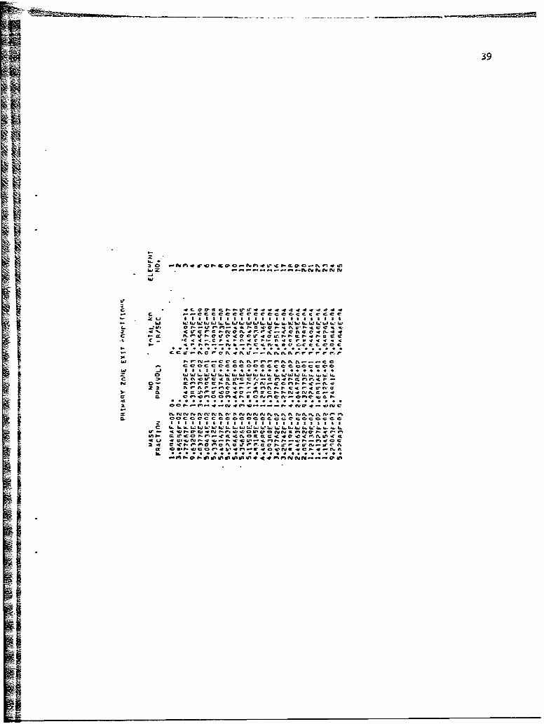
The norm-! output of a typical case continues with the items in
category 2-- elemental primary zone conditions for the converged solu-
tion. These items, which begin after a statement describing them,
consist of:
a. The mass fraction in the element.
b. The NO concentration in the element (ppm) (vol).
c. The cumulative sum of the NO formed up to and including the
element (lb/sec).
d. The element number.

2 6
Only those elements with a finite rate of formation of No areI iincluded in this output table.
The normal output of a typical case continues, after a statement
H describing the data, with the items in category 3-- over-all primary
zone exit conditions from the converged solution. This data sonsists
of:
a. The axial position in the combustor (in).
b. The mass mean primary zone equivalence ratio, accounting for
the inefficiency of the primary zone combustion.
c. The mass mean exit temperature of the primary zone (deg F).
d. The mass mean density of the primary zone combustion products
(lb/ft 3 ).
e. The mass mean primary zone residence time (msec).
f. The mass mean concentration of NO in the primary zone (ppm) (vol).
g. The mass mean concentration of NO in the primary zone, expressed
as NC2 (lb/l00 lb fuel burned).
h. The mass mean equilibrium concentration of C(S) in the primaryzone (ppm) (vol).zni. The mass mean equilibrium concentration of C (s) in the primary
zone (lb/1000 lb fuel burned).
j. The mass mean equilibrium concentration of CO in the primary
zone (ppm) (vol).
k. The mass mean equilib-ium concentration of CO in the primary
zone (b/lOO00 lb fuel burned).
:. The mass mean equilibrium concentration of unburned hydro-
carbons (exclusive of CO and C (S)) in the primary zone (ppm)
(vol).
m. The mass mean equilibrium concentration of unburned hydro-
carbons (exclusive of CO and C (S))in the primary zone (lb/
1000 lb fuel burned).
n. The fuel loading (lb/sec-ft 3-at.x 2 ).
The normal output of a typical case continues, after a statement
describing the data, with the itams in category 4-- over-all intermediate
zone conditions at axial positions in the zone corresponding to the
converged solution. This data consists of:

27
.. a. The axial position in the combustor (in).
b. The mass mean equivalence ratio, at the given axial station
in the intermediate zone, accounting for the inefficiency
of the primary zone combustion.
c. The mass mean exit temprature at the given axial station in
the intermediate zone, 'deg F).
d. The mass mean density of the combustion products at the given
axial station in the intermediate zone (lb/ft 3 ).
e. The mass mean residence time of the combustion products from
the comTbustor entrance to the given axial station in the
intermediate zone (msec).f. The mass mean concentration of NO at the given axial station
in'the intermediate zone (ppm) (vol).
g. The mass mean concentration of NO, expressed as NO2 , at the
given axial station in the intermediate zone (lb/1000 lb
fuel burned).
h. The mass mean equilibrium concentration of C(s) at the given
axial station in the intermediate zone (ppm) (vol).
P i. The mass mean equilibrium concentration of C(s) at the given
H axial station in the intermediate zone (lb/b00 lb fuel burned).
j. The mass mean equilibrium concentration of CO at the gi" n
axial station in the intermediate zone (ppm) (vol).
M k. The mass mean equilibrium concentracion of CO at the given
axial station in the intermediate zone (lb/bOO lb fuel burned).
I. The mass mean equilibrium concentration of unburned hydrocarbonsI (exclusive of CO and C(J at the given axial station in the
intermediate zone (ppm) (vol).
m. The mass mean equilibrium concentration of unburned hydro-
I carbons (exclusive of CO and C ( at the given axial station
iin the intermediate zone (lb/O00 lb fuel burned).
If the chemical rate of production of NO is frozen at any axial
station in the intermediate zone, the program prints a message to that
effect and proceeds with the dilution zone calculations and output.
The normal output of a typical case concludes, after a statement
describing the data, with the items in category 5-- over-all dilution

•- 28
zone conditions at axial positions in the zone correspondig to the
converged solution. If the chemical rate of formation cf NO was
frozen at any axial station ;n the intermediate zone, only the diluticn
zone exit conditions are printed. The data in this category consists
of:aR The axial position in the combustor (in).
b. The mass mean equivalence ratio, at the given axial station
in the dilution zone, accounting for the inefficiency of the
primary zone combustion.
c. The mass mean exit temperature at the given axial station 'n
the dilution zone (deg F).
d-. The mass mean density of the combustion products at the given
axial station in the dilution zone (lb/ft 3 ).
e. The mass mean residence time of the combustion products from
the combustor entrance to the given axial station in the
dilution zone (msec).
f. The mass mean concentration of NO at the given axidl station
in the dilution zone (ppm) (vol).
g. The mass mean concentration of NO, expressed as NO2 at the
given axial station in the diiution zone (lb/000 lb fuel burned).
h. The mass mean equilibrium concentration of C(s) at the given
axial station in the dilution zone (ppm) (vol).I i. The mass mean equilibrium concentration of C(s) at the given
axial station in the dilution zone (lb/100 lb fuel burned).
j. The mass mean equilibrium concentration of C(s) at the given
axial station in the dilution zone (ppm) (vol).
k. The mass mean equilibrium concentration of CO at the given
axial station in the dilution zone (lb/bOOO lb fuel burned).
1. The mass mean equilibrium concentration of unburned hydro-
carbons (exclusive of CO and C S)) at the given axial station
in the dilut;on zone (ppm) (vol).
m. The mass mean equilibrium concentration of unburned hydro-
carbons (exclusive of CO and C (S)) at the given axial station
in the dilution zone (lb/1000 lb fuel burned).
If the chemical rate of prediction of NO is frozen at any axial
station in the dilution zone, the program prints a message to that

effect after completing the dilution zone calculations and printing
the output at the axial position that corresponds to the c-cmbustor exit.
3.3.2 Error Messages andAdditional Output
In addition to the normal output, various messages may appear in
the output of a case. These messages either indicate that diffr7ulty
has been encountered during execution of the case or that the usar
has specified the printing of intermediate output to examine progress
in the iterat'ons. The messages are considered below in the order of
their appearance in the program.
a* If intermedipte output is requested by the user, the program
will print the value of the total mass contained in each
mixture ratio element and the value of the parameters that
define the range of the mass distribution function. These
values are printed in Subroutine ZMASS; they are printed
for each converged axial position in the combustor.
b* If, in calculating the values of (ol), the number of
iterbiions on a given element equal ten, the program prints
"the number of iterations and the last value of ( t,)i.
This is a nonfatal error as the prugram assumes the value
of ( d-.)i to be the last value calculated. The error
message is printed in Subroutine PRCALC. This error is
caused by limiting the number of iterations to ten; it
can be relieved by increasing the limit.
c. POTENTIAL ERROR DUE TO LACK OF CONVERGENCE, SUMTNO(I)
+X.XXXXXXXXE+XX PRIOR VALUE OF SUMTNO(i) = +X.XXXXXXXXE+
XX I = XXX -
This message is printed in Subroutine PRCALC for a primary
zone element that fails to satisfy convergence criteria after
five iterations. This is a nonfatal error as the program
assumes that the value of SUMTNO(i) is the last value cal-
culated. The error is caused by limiting the number of
iterations to five; it can be remedied by increasing the
limit.I1

30
d. If intermediate output is requested by the user, the program
will print the value of the nitric oxide content of eac~h
mixture ratio element for each converged axial position in
the combustor. These values are printed in Subroutine PRINTS.
8. If the number of iterations attempting to satisfy the mixing
criteria equal 40 for any mixture ratio element at any axial
station in the intermediate zone, Subroutine ZI.NTER will
print the most recent value of E., and the number of iterations.This is a fatal condition to the program causing immnediatetermination of the calculations. This procedure is a safety
control to keep tf- program from continuing into an indefinite
loop; it is likely caused by some trouble in the calculation'
of-element masses and can only be remedied by dete*led exami-
nation of the flow rates into and out of-each mass element.
f. X(CM) = +X.XXXXXE+XX J = XX
AVE. RHO(GM/CC) = +X.XXXXXE+XXAVE. NO(GM/GM) = +XoXXXXXE+XX-
This message is printed from Subroutine ZINTEA at the end of
each iteration loop in the intermediate zone if intermediate
output is requested by the user. The meaning of the message
is quite clear; both the density and nitric oxide concentrations
are mass averages. J is the number of iterations.
go RUNGE-KUTTA ITERATION FAILED TO CONVERGE TO SPECIFIED LIMIT,
DIFNO = +X.XXXXXE+XX N = XXXX X = CMS
This ncnfatal message is printed by Subroutine ZINTER at each
axial position in the intermediate zone where convergence
criteria on the NO iterations are not satisfied. N here is
the number of steps each major step is divided into for the last
iteration; DIFNO identifies the difference in the'calculated
nitric oxide levels at the end Qf the major step down ihe
combustor tD position X. There are two possible reasons for
the appearance of the message:
"I. "e number of steps allowed in the Runge-Kutta integration
are inadequate.

31
2. The convergence-limit is too narrow.
Relaxation of either of these control criteria will eliminate
the iteration difficulty.
h. X(Cti) = +X.XXXXXE+XX J = XX AVE.RHO
"GM/CC) != +X.XXXXXE+XX AVE. NO = +X.XXXXXE+XX
+LX.XXXXXE+XX +X.XXXXXE+XX
This iessage is printed from Subroutine DILUTE at the end
of each iteration in the:dilution zone if intermediate
output is requested by the user. The-meaning of the me6sage
is quite clear except for the last two variables printed;
these variables are rate qf change of nitric oxide mass
fraction with position due to chemical reaction and, dilution,
respectively. Both the density and nitric oxide concentrations
are mass averages. J is the number of iterations.
' if intermediate output is requested by the user, Subroutine
DILUTE prints.the difference between the calculated nitric
"oxide levels for the last two iterations at the end of each
major step down the combustor. In dddition, DILUTE also prints
the number of integration steps each major step is divided
into for the last iteration.
j. RUNGE-KUTTA ITERATION FAILED TO CONVERGE TO SPECIFIED LIMIT.
DIFNj = +X.XXXXXE+XX N = XXXX X = +X.XXXXXE+XX
This nonfatal message is printed by Subroutine DILUTE at
each axial position in the--dilution zone where convergence
cri~teria on the NO iterations are not satisfied. N here is
the number of steps each major step is divided into for the
last iteration; DIFNO identifies the difference in the
calculated nitric oxide levels at the end of the major step
down the combustor to position X. There are two possible
reasons for the appearance of the message:
I. The number of steps allowed in the Runge-Kutta integrationa
are inadequate.
2. The convergence limit is too narrow.
* Relaxation of either of these control criteria will eliminate
the iteration difficulty.
32
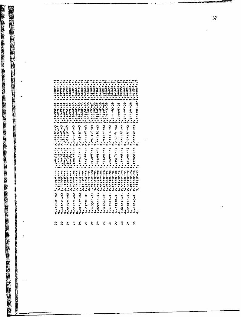
3.3.3 Description of Sample Case Output
The output from the fictitious sample case described on pages
33 and 34 is presented on pages 35-42. The data on pages 35-38
represents the input data for this fictitious case while calculated
results are shown on pages 39-42. From the data it is seen that the
Smean primary zone residence time for the combustor is 2 msec; and,
in that time, a mass average concentration of 300 ppm (vol) of nitric
oxide has been formed. Within a distance of 1.5 inches down the
combustor intermediate zone, the chemical rate of formation of nitric
oxide is negligible in comparison with the amount of nitric oxide
previously formed. Consequently, only the dilution of the total
nitric oxide formed to that point is important to the final emission
figurt of 73 ppm (vol).
3.4 MISCELLANEOUS OPERATIONAL INFORMATION
Program GASNOX occupies approximately 20,000 core locations during
loading and approximately 12,000 core locations during exectution on
the CDC 6600 computer. Actual program length is approximately 7100 core
locations. Hence, the total storage requirement for this program is
comfortably witi'in the CDC 6600 core capacity of 131,000 locations.
The execution time for Program GASNOX depends upon the characteris-
tics of the particular combustor being analyzed. It has been found,
however, that a typical case will require approximately 10 to 15 seconds
of central processor time on the CDC 6600 with another I to 2 systems
seconds necessary to satisfy input/output requirements, Approximately
12 systems seconds are required to load and compile the program.
There are no known sources of convergence diffi. - in the program
save the limits imposed on the number and accuracy of the Runge-Kutta
integrations. These requirements are adequate for most applications of
the program; they are neither too restrictive to cause convergence diff;-
culties nor too loose to permit an abundance of interations and
excessive com-,uter costs.

NORTHERN RESEARCH AND ENGINEERING CORPORATION 333.5 DATA INPUT SWEET
NOx frai GasENGINEER, RDS PROJECT. Turbine Ccxrbustors PROJECT NO, 1 162L
TITLE* Sample to Illustrate the Use of Program r.Z; ShEETIOF 2
OCATION
Line- 1 1.
Line 2 FUEL=, C 1.0 900~±00 ±I001" ~'2,3000011 +00 INLEr- AIR T.fK.)= 7. OOOO0Q0OE+02
Line 3 PRESS, .(ATM = 5.7800000 OEi-CZ,,CDE= 2,pH, s0l0i.= 6j22 E
Line 4 &486i79-04 1.24 9 .ýE02 2.785E-03 7.324.0(+02 6.546, E-07 0.
Line 5 U. 79E 0. 0. .0OOE+35 l.OOO4XE+35
Line 74 _ ,_ _ II I
Line 75 , 0.0 , 20 0 3.0 O. F 0.0
Line 76 , 1.0 , 30.0 , 3.0 , 0.0 _ 0.0 __,
Line 77 2 2.0 __ 3.L0. 3:0 .0.0 0. __
Line 78 ,3-0 LO_ 3.0 0.0_ __ _ ____
Line 79 4. , 45 , 340 , 0.-_ 0. ___Line 80 5.0 ,500 30 , 0.0 , 0._
Line 81 , 6.0 , 60.0 , .9 , 0.0 0.
7. 70. 3.0 0.0 0.0
Line 83 , 8.0 180.0 . 0.0 _
Line 84 , 9.90 90. . 3.. 0.01 _
Line 85 10.0 . 100. . 0.0 .. 1
Line 86. 1

NORTHERN RESEARCH AND ENGINEEERING CCRPOR-TION34
3.5 DATA INPUT SHEET
NOx from Gas
ENGINEER, RDS PROJECT& Tu rbine Combustors PROJECT NOs
ED TITLE, Sample to lllustrate-,,he Use-of PrcqramGASNOX SHEET 2 0F 2
! LOCATION
I az 1, ja 9 2,43l A IT 4 . to 64 00 W 4,67 73
Line 87 -,;-- , __10. 0.9 , 0
Line 88 , . 1.0 0.0 O
.. I. I . II ,_. _ 1: __,,
I j
.- •I _ _ _ _ _ _ _ _I _._ __,_ _ _ _,__ _,__ _
____ ___,___ , ___, __ __ - __ _ _ _ _ _ .... . ___ __ __ __ _ __ _ __ _ _ __ _
_ _ _ I _ _ t _ _ _ _ _ _ _ _
_ _ _ _ _ I I j _ _ _
_ _ _ I _ _ _ _ _ _ I*
t -
_ _ _ _ _ _ _ I _ _ _ _
SII_ _ _ _ _ _ I __ . . . . ._ I
_____ ____ ____ ____ ____ ____

35
a & a a 00 a a~ a
0 0 0*Oa 0* 0 . 0
in Inf Ilin
a, (p 0. a. a.c .C)or x
o vo x Ip a 0, a ap ,0
C* x
CL it sfa ls l bl 61 1 %
Ln c * c c c I 0O
Lai C.) c 0 0a 0caC,6X. . ý c2c -a a -I-J ai o ge. .... **0 2 aa o_ 10 0 0 c 40 0~C CICr
1.A CO C C CCC 40 40004 oC 01C LnC 24 rf- .cil in j. onI rl rm kon l % i cr * o
4A T In 2 II
rl -4 w -w -e mfON ul mCC.. a.... at OP c &-~4-1 c Ic 00 a0000.00. :w2 CCLaCLma (pag
Lb L6 W ~ ~ I'E W. WWWU
L). cc2aC ,4 -4 aO
hi 2 2 a i IC C - f ,r
*o o
IL 2A I& IL LL 2L L % L I h*~c 20 40 2l I) a
40 47, cccc c~ It I-2 7 c* ~ ~~~~ 'r 4.) , uCO ~ C
a In 2D 0c n0 4-%20 20 *l 2

11 36
C t~rc
da.,4 0 nZ
a.w .Ic acz
C -i
CL
Iz f- 94-i nM P zm ,mnM %ete 7 -Z= 15 2 1 a 8 1 , I 1 3 seCa Ca~ CCC C.
a -a- 4 *ssii ii a isss ,asaai.ia ii
t r:
4A A, ft r -e r.5. 'a C.,'m 0 .r .* C, , a r!-a e c t. i- - - ar. a. r- a mI. 0 f cu &L - i c N040fr0c. c I C 0 ~ ~ ~ aCN C ~ tCf-
C_. 4C, an a-C' ..-00a -04C.-C4 c2NUft44r.'C, ~ to 5- a.=, "V acc c t*4 r v a . " 1 , L
4 c Q -.- cccceccccaccc-cccc .C%.-
C Z-0 aC a f 0- m4- C C f V a 4 4 M a ? t....ý a-tf-a C a- 11a-- :i C 4
a 2 !Z'*1fu* * a. .1-.. .-. a.. . . .a.. . . . ..9.CL
c cv a -C sr r- C C. c C a C rZ feec cc cc c .cc ecC. md4 'Mf =g a 5~ c- au a. i, a a a s 1 55 i i i 55 5 5 i
M cc 1a. c. a. C ca ak a a a aw aý n~ cc a.; a1..aa .5.aaa.a.S..aa-C -W. C>S. .0 U. C> N 0 Nr m c a. d.-
-~~~U Cts 1.-. ' a &- c W - 1-c 4f !P d' -a ela at.PE0 4' ~C P 0 a-,L: I . .. I I .. .- . I ,Cý . re C. .~U, a C CS- UZft -vc Ma Cva nC 4v 4. - £-C C C00 O-C -1
C - ft MtCtia.-4 4 4 4 -. 4 -u ft -40 c4C M. M %.cu Ul. up ~ -co aC. C, . £ ~ c c c c crc c c a. -ý e o l CD,0
i-I ij' a. a~ .a. ca 5aaL~~.aa ~ ... Sa.) r-I d:C4-a-.T C CO .SC cP~~.0C~ N m A M a el -
IC 2 Z.
a-- paS
ii 37
Eli'UPap O0e O~J ~~~b t~l00
co C. In ,o l~ c _ , u wb~l~ lU S2l:ýr -CU at. it. &fCCCCC C.SC1 C obC oc c--~mbO ob P b b
90,1 acu~a a a . c
a ~ ~ ~ C.-C -o e C. C- oa ft c CLP C-C .. 1 N .C -. c. Q c o4~~4a 4C bC C-C) Co c C C
C0 C cC C a C c c c c
C. 4l fn 404 Cn 4040 c- I'.4 0 0 M . fn Mb
- Ua .a . .a. . .a.a.a ka.a . . .a. a. . c-a I" aa. . .ft A ~C c P-C ftC I c
C.-C 4%-% Ng c r, C% i C C - N--C a C C C>s~
ý r- A4 a 4 c 4I. -4 in i~t. t LC
Ma aC% m a
c -a. a. 0 a. a. . a c. 1. o a a. a, - a. 10 o
SR 0 N- c~ Ne C'a c & 4o-r .wb .0 C N c- 4 N
V c 4 c r vJ a. - N v J c M c ct I- C r ý i c cc
N-4 mb .0 am v0 m 4 m - N
N* Nu N "N N co ft ca v ~ -
Is

I-L *d
Z.A.
* - 2 2
ir L
C, I .. j
C, n II
2) I * 0.
co .j 0-- a -
U% zn 4D 41
- 06 0 w0 0' 0 a-
P4 ~ *0* I-0
1- in -
>. > .~ c .* -oL 02 Q- w wd aI= w z *ý en
W. tn n
LII -. = -.~~: o z 0
.> -Z. .L_ -ý c~.C -
w C, C~ 2.1 < a
cc3a-- 0 cc w Lo
Q 4i w . a- i 0 W
:.. - ~- x :., Q - 'a. a.tS. * - 5w LL w a UU i Lo LX cr 2 2 2
39
•3c c c c c--Cm- C C
Il1 LL L.aI Z AI
ci r- : C oc c C.oo Ic~ c cc
o ~ ~~~~~~~~ .i .I I. aL . iL iL .S .i . .wS. . S. S.
2jV 1tfP. SI m- ccc tf r C -4S ftft~ C .Sft c
aflw -Zan ~ rc~ew=4fvr m9% f-C -Icc;r;eCl% P cCMw-:1ru -o
4. a .0 -c. c. SC±1=c => aQ C= cc- ccs
L :=11LIL; 1W 11wIrw-ý .2I oanw=c -ýw-.

1 40
C
man cc-
LVJo I--
CU;
C,
0 CL cc0 1
. J.-k *
W" C3 cI
x _j
hi CL 0
int CL
0.0 -ic
P4 Ik4
0 CL C3lwC
* 7h.
0cc -a,'
a *
CJ~ alaI- w a%
In a i
Z (
GM LLZ>C) m
Zl C> .
- 31C

41
Cc WO c 0 4= .0
CLi w 0 r 0 -#
U)f c gn r- ICYcc 0 oý 0. 0
i mi 40 C. 40*~
x .CL 0 u & rl D 4mP- %a 4
c Ze :w 0 0 0 C3
W -J= .0 0* . *Q1x =i * L k:.: a.. w i
C :, N V % 0 1
91 AL :I en &P
4r a M
- c c
.h. I& C
CA I 3ia. 0
I a
La I= z , C, C =
0 ~ .0 c1 n e
7i1.3 L La. .2 L
w -j A, a.. .. ra I
z CDC.
I .- : c
I.. D a aj 2 an-
u ;J r- I W4
4ra L- 4pa C
-Ct .0 i .- I-
M. * I C-
C, C3,i c- cza- * .0 ~ar
to.~

42
C CL
Ucc I--
-i 4 -ichw
Xo~ CL0-Q CL> .0
- N
iim
en c.r- ~C3,_
2 2i cr
*~ * ) -hi
2.m C)
0 -oV CL
I- - J
0o0
CC
C.C) C.)hi
-KN 0.- ~ C5 -
aM
II
3--
I-.

Ii 43
4. REFERENCES
1. Danckwerts, P. V., "Continuous Flow Systems, Distribution ofResidence Times", Chemical Engineering Science, vol. 1, 1953,pp. 1-13.
2. Jackson, S. R. and Odgers, J., "Factors Influencing Heat Releasein Combustion Chambers and Consideration of the Related Materialsand Structures", Combustion in Advanced Gas Turbine Systems,Proceedings of an International Propulsion Symposium held at theCollege of Aeronautics, Cranfield, England, April, 1967.
3. Fletcher, R. S. and Heywood, J. B., A Model for Nitric OxideQ Emissions from Aircraft Gas Turbin.i Engines (AIM Paper No. 71-
123), American Institute of Aeronautics and Astronautics,Presented at the AIM 9th Aerospace Sciences Meeting, New York,N.Y., January 25-27, 1971.
ORH
44
5. FIGURES
E :
ii.I
45
IPRIMARY INTERMEDIATE DILUTION
WIRLER AIR
S"a CROSS- SECTION of COMBUSTOR LINERSHOWING MEAN- FLOW PATTERN
IAEl F,,,axI
ALONG LINER -LENGTH
F AT POSITION A
I AREA REPRESENTS
f(F)MASS~ FRACTION
-
1.. F~-(c) DISTRIBUTION of MASS AS A FU NN
of MIXTURE RATIO and POSITION
-'- ---IFigure rASSUMED FLOW AND DISTRIBUTIlOIN PATTERNST•IROUGHOUT COMBUSTOR LINER

46
4.100.
90
Is K
S70
iN
160
50 - . I I I0 .02 .04 .06 .08 .10 .12 .14
FI.ZUL LOAD FAWTO8
1, /VY P2 -Ib/sec f-3 Arm2
REPRODUCED FROM REFERENCE 2Figure 2 PRIMARY ZONE
COMBUSTION EFFIC.IE•Y CORRELATION

S~47
Category CategoryN Catgory (3)
(2) DataData F
Category(1) 1 4Data
Sfiz
Entry Point
FIGURE 3 - SCHEMATIC REPRESENTATION OF INPUT STRUCTURE

1 48
GASNOX
MINT
ZAS
CHEKKCALCB . M INT
PR RATPRCALCý
PR I MRY MIINT
PR I NTS
M INT
ZMASS T
CHECKK CALCBi N T NT
IFZ I NTER RUNKUT DERIV
II
M I ,•rr
.a
LAPR I DTS
ZMASS IM I NT
M I NTrD I LUTE
RUNKUT DERI V
PR INTS
FIGURE 4.." MODULAR, TREE DIAGRAM

49
6. NOMENCLATURE
Symbols Description
A' Preexponential factor in Arthenus equation
N Total cross-sectiona] area of combustor liner
A] Model constant inequation A-15
A2 Model constant in equation A-24
A3 Model constant in equation A-24
0 CoefficLe~t-in combustor efficiency parameter
C Normalizing factor in distribution function
"Activation energy
"F Fraction of mass &rn
F Mixture ratio, (fuel mass/total mass)
k Reaction rate constant
K Fraction of mass &lvnleaving control value over SYL Length of intermediate zone
Total mass flow rate in combustor linerI Mass flow rate of diluent air per unit lengthMao Moleculer weight of nitric oxide
[Ndj Mass fraction of nitric oxide, (Mass NO/total mass)
LwO3 jwo'- NOMd3Pressure
Rate of.formation of nitric oxide per-unit volume
Gas constant
Equilibrium rate of reaction,
t Time
T Temperature
iV Velocity
Characteristic combustor velocity
Volume of primary zone
X Axial distance9A Cross-sectional area of element with mixture ratio F
iMass rate of element with mixture ratio F
Range of F about F in element with mass
Nitric oxide concentration as fraction of equilibrium
I _
>0
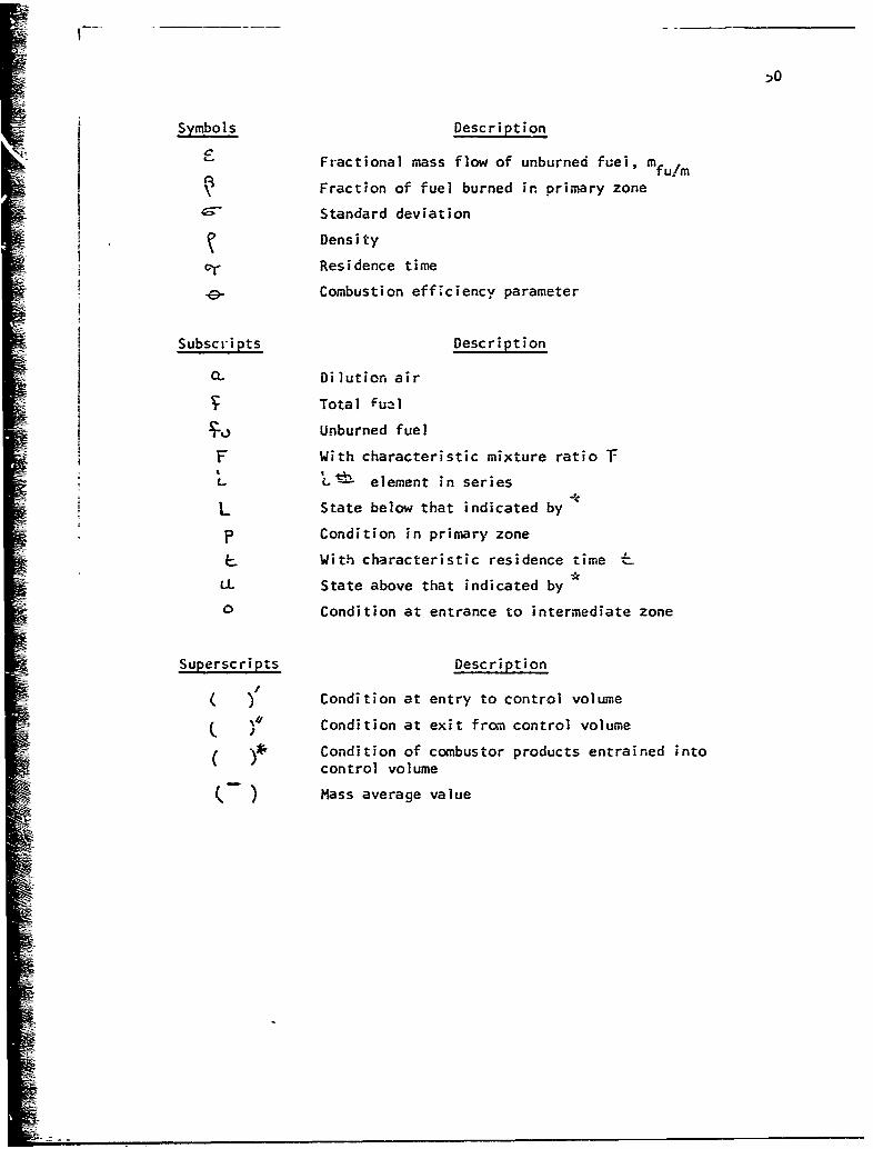
Symbols Description
Fractional mass flow of unburned fuel, mf/
Fraction of fuel burned in primary zone
__Standard deviation
Density
V Residence time
Combustion efficiency parameter
Subscripts Description
oL Dilution air
Total u2ul
Unburned fuel
F With characteristic mixture ratio
L • element in series
L State below that indicated by
P Condition in primary zone
With characteristic residence time &LL State above that indicated by
0 Condition at entrance to intermediate zone
Superscripts Description
( )/ Condition at entry to control volume
C u Condition at exit from control volume
S( •~ Condition of combustor products entrained intocontrol volume
-' ) Mass average value

51
7. APPENDICES
R
52
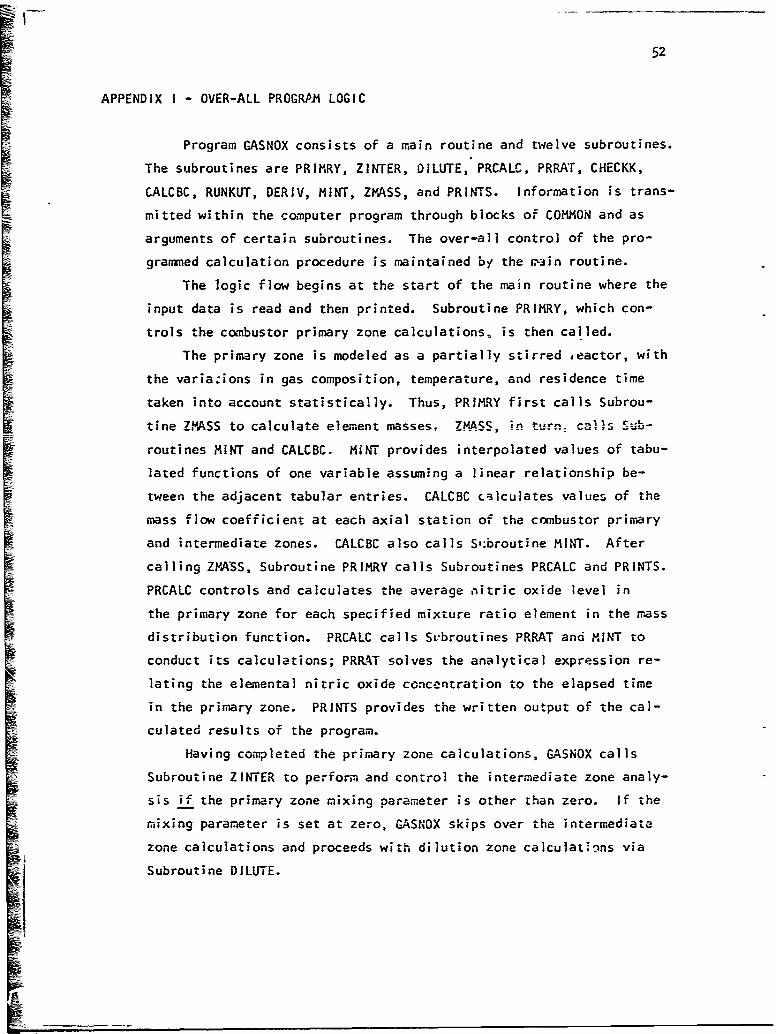
APPENDIX I - OVER-ALL PROGRPA LOGIC
Program GASNOX consists of a main routine and twelve subroutines.
The subroutines are PRIMRY, ZINTER, DILUTE, PRCALC, PRRAT, CHECKK,
CALCBC, RUNKUT, DERIV, MINT, ZVASS, and PRINTS. Information is trans-
mitted within the computer program through blocks of COMMON and as
arguments of certain subroutines. The over-all control of the pro-
grammed calculation procedure is maintained by the r.iin routine.
The logic flow begins at the start of the main routine where the
input data is read and then printed. Subroutine PRIMRY, which con-
trols the combustor primary zone calculations, is then called.
The primary zone is modeled as a partially stirred ,eactor, with
the variazions in gas composition, temperature, and residence time
taken into account statistically. Thus, PRIMRY first calls Subrou-
tine ZMASS to calculate element masses. ZMASS in tSub. calls S"-
routines MINT and CALCBC. MINT provides interpolated values of tabu-
lated functions of one variable assuming a linear relationship be-
tween the adjacent tabular entries. CALCBC calculates values of the
mass flow coefficient at each axial station of the combustor primary
and intermediate zones. CALCBC also calls S';broutine MINT. After
calling ZMASS, Subroutine PRIKRY calls Subroutines PRCALC and PRINTS.
PRCALC controls and calculates the average nitric oxide level in
the primary zone for each specified mixture ratio element in the mass
distribution function. PRCALC calls Svbroutines PRRAT and MINT to
conduct its calculations; PRRAT solves the analytical expression re-
lating the elemental nitric oxide concentration to the elapsed time
in the primary zone. PRINTS provides the written output of the cal-
culated results of the program.
Having com-pleted the primary zone calculations, GASNOX calls
Subroutine ZINTER to perform and control the intermediate zone analy-
sis if the primary zone mixing parameter is other than zero. If the
mixing parameter is set at zero, GASNOX skips over the intermediate
zone calculations and proceeds with dilution zone calculations via
Subroutine DILUTE.

53
The intermediate zone of the combustor is divided into a series
of finite length axial elements in which the heterogeneous products
from the primary zone mix with one another and with the entering
cooling air. By the end of the zone the distribution is collapsed
to a uni-dimensional profile. To accomplish this mixing process
ZINTER calls on Subroutines ZMASS, CHECKK, RUNKUT, MINT, and PRINTS.
The function of Subroutines ZMASS and MINT are as before; PRINTS
writes the calculated mass mean conditions at the end of each fi-
nite length axial combustor segment. Subroutine CHECKK calculates
the proportionality constant between the mass flow rate out of an
element due to mixing and the total mass flowing into it at a given
axial position in the combustor. RUNKUT is employed to obtain the
solution to the first order ordinary differential equation between
I nitric oxide concentration and axial position in the combustors by
the Gill variation of the Runge-Kutta numerical integration scheme.I In doing so, RUNKUT calls Subroutine DER!V which calculates the rate
of nitric oxide formation with respect to axial distance in the com-E bustor intermediate or dilution zone.
In the dilution zone, the flow is uni-dimensional with the gases
uniformly mixed across each cross section. To perform and control
these calculations GASNOX calls on Subroutine DILUTE. DILUTE in
turn calls on Subroutines ZMASS, MINT, RUNKUT, and PRINTS for calcu-
lations and printout at specified axial stations in the zone. The
only deviation of these subroutines from their previously described
functions occurs in ZPASS: since the mixture ratio distribution is
collapsed to a flat profile, it omits reference to Subroutine CALCBC.
This concludes the description of the over-all logic structure
of Program GASNOX. A modular diagram of GASNOX is provided as Fig-
ure 4.

54
APPEIDIX-'II - COMMON FORTRAN NOMENCLATURE
The following tables zontain the COMMON Fortrap noimeqclature
for Program GASNOX. COMMON consists of seven labeled blocks; the
nomen-.lature is arranged in alphabetic order for each block. Singly
subscripted arrays are indicated by their respective indices.
I - Element index
J - Incremental station index for the X direction
K -Distribution index
SNomenclature for COMMON/DATAI/
Fortranio •Symbol Description Units
AIR(J) M Combustor airflow at axial station X gm/sec
ATT(I) Ti Adiabatic flame temperature for anelement i deg K
Al Ai Exponent in relationship governingcollapse of mixture ratio distributionfunction
A2 A2 Factor in relationship defining the rateat which unburned fuel is burned in theintermediate zone
A3 A3 Exponent in relationship defining the rateat which unburned "uel is burned in theintermediate zone
BCONI(1) (C(s)i)e Equilibrium mole fraction of carbon foran element i
BCON2(1) (COi)e Equilibrium mole fraction of carbon monoxidefor an element i
BCON6(I) (NOi)e Equilibrium mole fraction of nitric oxide foran element i
BETA Combustion efficiency in the primary zone
CH2(i) (CH2i)e Equilibrium mole fraction of unburned hydro-carbons exclusive of C(s) and CO for an element i

55
aFortranSymbol SS.bol Descriotion Units
SCN CN Mixing characteristic
CUMDIS(K) Value of cumulative normal distribution
ENS ks Fuel-to-air mass ratio at stoichiometricconditions
EKI(I) (Kl)i Ratio of fcrward reaction rate constants(see Volume 2, Section 2 or Ref3 )
EK2(l) (K2)i Ratio of forward reaction rate constants(see Volume 2, Section 2 or Ref3 )
FF(1) Fi Mixture ratio
FNOXP (NOo) NO formed in the flame front ppn
PHIP Vp Mean primary zone equivalence ratioaccounting for the inefficiency of theprimary zone combustion
PPP P Operating pressurt atm
RHO Ci Density of combustion products for anelement gm/cm3
RR(J) PX Radius of combustor liner if canannularconfiguration; equivalent radius ofcombustor liner if annular configuration in; cm
RI(l) (Rl)i Forward reaction rate for the firstkinetic reaction (see Volume 2, Section 32 or Ref 3) 9i..-mole/cm -sec
R6(0) (R6 )i Forward reaction rate for the sixthkinetic reaction (see Volume 2, Section2 or Ref 3) gm-mole/cn3-sec
S so Degree of mixedness in the primary zone
VP VP Volume of the primary zone in3; cm3
XEND XEND Length of intermediate zone and dilute
zone (combined) in; cm
XL XL Length of intermediate zone in; cm
Xx(J) X Axial position in the coMbLscor in; cm
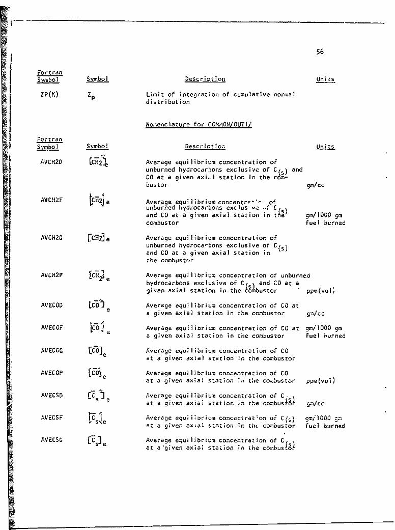
56
FortranSvmbo I Description Units
ZP(K) zp Limit of integration of cumulative normaldistribution
Nomenclature for COM;ION/OUTI/
FortransymboIm bol. Descriotion Units
AVCH2D £cii4 Average equilibrium concentration ofunburned hydrocarbons exclusive of C(s) andCO at a given axi.l station in the com-bustor gm/cc
AVCHiF H 2e Average equilibrium concentrp"r ofunburned hydrocarbons exclus Ve ..f CCaand CO at a given axial stat ion in t.4'~ gin!1000 in'combustor fuel burned
AVCH2G ECf2Je Average equilibrium concentration ofunburned hydroca-bons exclusive of C(,%and CO at a given axial station inthe cchibustrir
AVCH2P JCHe Average equilibrium concentration of unburnede hydrocarbons exclusive of Cs% and CO at a
given axial station in the do8Ibustor ppm(vol;
AVECOD 0 Oe Average equilibrium concentration of CO ata given axial station in the combustor 9-I/cc
AVECOF ICOI Average equilibrium concentration of CO at gmIlOO0 ema given axial station in the combustor fuel burned
AVECOG CeO Average equilibrium concentration of COat a given axial station in the combustor
AVECOP COe Average equilibrium concentration of COat a given axial station in the combustor ppzI(voi)
__ISeC e Average equilibriLm concentra:ion of C.at a given axial station in the co.nbusto cm/cc
AVECSF Average equiiiorium concentrat'on of C(s) gmilO00 cmat a given axial station in tht combustor fuel burned
AVECSG LCO Average equilibrium concentration of C.at a'given axial station in the combus or

57
FortranS Sybombol Description Units
AVECSP Average equilibritu concentration of C s)SS at a given axial station in the combuslor ppk(vol)
Nomenclature for COMON/OIJT2/
Fortr3nsymbol Symbol Description Units
AVENFU rNOI Average nitric oxide concentration at !;-l0O gmup prior axial station in the combustor fuel burned
AVENOD [NO] Average nitric oxide concentration ata given axial station in the comLbustor gca/cc
AVENOF wNo] Average nitric oxide concentration at M/lOOO gm
a given axial station in the combustir fuel burned
AVENOG LN7O0 Average nitric oxide concentration ata given axial station in the conbustor
AVENOP 1Nko Average nitric oxide concentration at agiven axial station in the combustor ppm(vol)
MlAST IndicatorILAST - 0 if the nitric oxide chemicalreaction is not frozen at a given axialposition in the combustorILAST = I if the nitric oxide chemicalreaction is frozen at a given axialposition in the combustor
RRO ()rr Mean denrity of combustion products at agiven axial sta'on in the cw.bus:^- gm/cc
Nomznclature for C0Gt.%ON/OU-3/
FortranSymbol SVmbol Description Units
AVET T Average temperature of combustion productsat a given axial station in the combustor aeg K
FBARD T Mean mixture retio at a given axial stationin the combustor
IAX itX Subscript of mass element with highestequivalence ratio
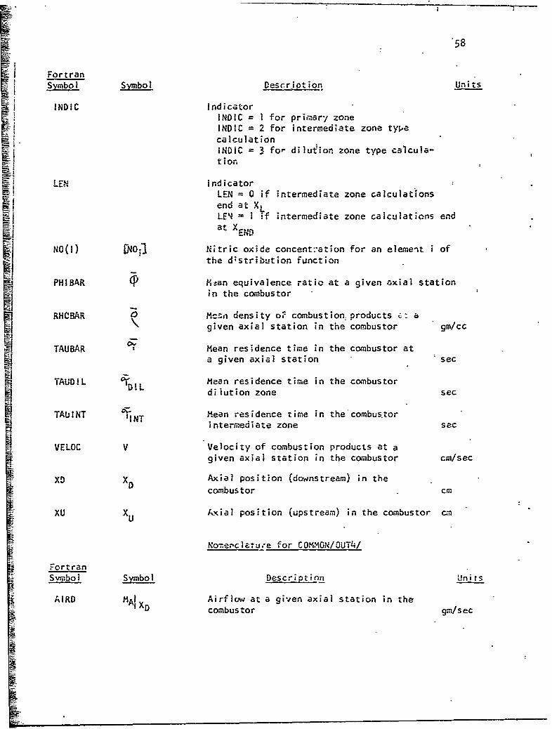
58
Si Fortran
i Symbol Symbol Descriotion Units
•! INDIC IndicatorNINDIC = I for priimary zone
INDIC = 2 for intermediate zone typecalculationINDIC = 3 for dilution zone type cslcula-Iition
LEN IndicatorLEN = 0 if intermediate zone calculationsend at X,"LE = I if intermediate zone calculations endat V"^END
NO(i) [NOj3 Nitric oxide concent:'ation for an element i ofthe d;stribution function
PHIBAR Pstan equivalence ratio at a given axial stationin the combustor
RHCBAR Mc~n density o0 combustion, products c: agiven axial station in the combustor Qm/cc
TAUBAR Mean residence time in the combustor ata given axial station sec
TAUDIL 0'D!L Mean residence time in the combustordilution zone sec
TAUlNT -INT Mean residence time in thecombus.torintermediate zone sac
VELOC V Velocity of csmbustion products at agiven axial station in the combustor cm/sec
XD XD Axial position (downstream) in thecombustor cm
XU XAU xial position (upstream) in the combustor cm
Nomerclatu.-e for COMMON/OUT4/
FortranSvmbol Sy.bol Description Units
AIRD i Airflow at a given axial station in the
AXD combustor gm/sec

59U
FortranSymbol Symbbl Description Units
ANDO Average nftric oxide concentration atA14a given axial station -in the combustor
* AQQ Q Measure of the round-off error in theRunge-Kutta integration routine at agiven axial station in the combustor
AREPD AX Cross-sectional area of combustor at a 2D0 given axial station in the combustor cm
ASLOPE kA) Rate of change of airflow rate in thecombustor' liner with axial position ata given axial station in the combustor gm/sec-cm
AVEMW MW Average molecular weight of reactionproducts at a given axial station inthe c6mbustor gm/gm-mole
CI W3NOU(1) [N' iue Nitric oxide equilibrium concentrationfor an element i of the distributionfunction
DDM(1) (Mi)D Elemental mass flow rate at the down- Sstream limlit of integration gm/sec
DELMDO() (baii) Elemental mass flow rate at the down-D stream limit of integration gm/sec
DIFNO(i) Difference in NO concentrations forsuccessive iterations for an element iof the distribution function
DMDDA(1) (SmA) Elemental mass flow of gases into control
nAi volume due to mixing of the ..ilution air
with previously mixed gases gm/sec-cm
DMDDM(i) (Sm M) Elemental'mass flow of gases into controlvolume due to mixing action of gases alreadywithin the combustion liner gm/sec-cm
:DMDDP(I) (sm'). Total elem, ental mass flow of-gases into1 control volume due to mixing gm/sec-cm
.DMDDPP(1) (Sm"). Total elemental mass flow of gases out ofcontrol volume due to mixing qm/sec-cm
DMFFED (Mf)fed Total mass flow of fuel fed to the com-
bustor gm/sec
A3

6o
FortranSymbol Symbol Description Units
DMFT (Mf)XD Total mass flow of combusted fuel at aD given axial station in the combustor gm/sec
DMFUD (Mf)X Total mass flow of unburned fuel at agiven axial station in the combustor gm/sec
DMFUO (Mf)o Total mass flow of unburned fuel at theprimary zone exit gm/sec
E(I) E. Proportionality factor between mass flowrate out of an element i due to mixing andthe total mass flowing into it cm
EKKD KD Proportionality factor between mass flowrate out of an elament due to mixing andthe totalmass flowing into it cm
FB(I) (F8 ) Boundaries between which each mixture ratiovalue applies
FPRIME(I) (F')i Mixture ratio at entrance to elemental controlvolume i
NOEQXD [N-6 Mass average nitric oxide equilibrium concentra-XD tion at a given axial station in the combustor
NOP(1) CN03i Nitric oxide concentration of the mass flowinginto an elemental control volume due to mixingat a given axial station in the combustor
NOZERO(I) IndicatorNOZERO = 0 if chemical rate of production ofNO i.n an element i is finiteNOZERO = 1 if chemical rate of product of NOin an element is zero
RDOT(1) R. Elemental rate of change of unburned fuel withaxial station in the combustor gm/sec-cm
RSUBX Rx Combustor radius at a given axial stationD in the combustor cm
SIG 4- Standard deviation of the distributionfunction at a given axial station inthe combnstor
SIGZER IS7 Standard deviation of the distribution functionin the primary zone of the combustor
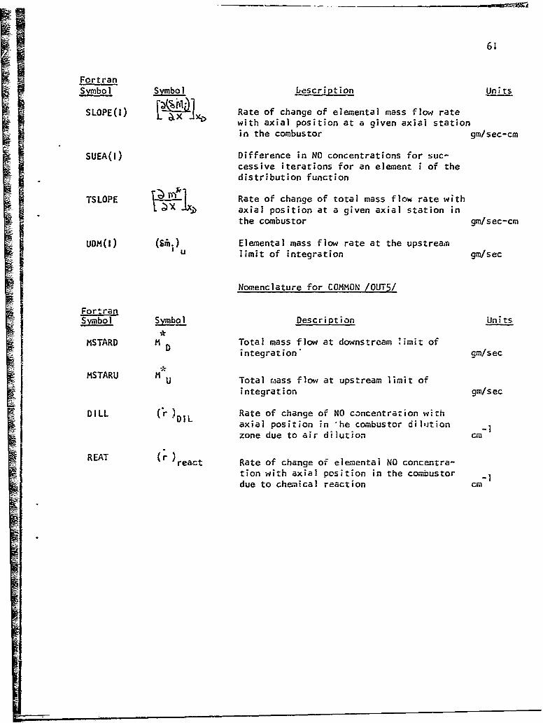
61
Fortran____ _ Symbol bescription Units
[SOtPE(I Rate of change of elemental mass flow ratewith axial position at a given axial stationin the combustor gm/sec-cm
SUEA(I) Difference in NO concentrations for suc-cessive iterations for an element i of thedistribution function
TSLOPE Rate of change of total mass flow rate withI. JXj .axial position at a given axial station in
the combustor gm/sec-cm
UDM(I) Elemental mass flow rate at the upstreamU limit of integration gm/sec
Nomenclature for COMMON /OUT5/
FortranSymbol Syjmo4l Description Units
MSTARD 1 D Total mass flow at downstream limit ofintegration' gm/sec
MSTARU M Total mlass flow at upstream limit of
integration gm/sec
DILL (r )DIL Rate of change of NO concentration withaxial position in 'he combustor dilution -1
zone due to air dilution cM
REAT (r )react Rate of change of elementai NO concentra-
tion with axial position in the combustor -ldue to chemical reaction cm

62
APPENDIX III - MAIN ROUTINE GASNOX
The principal function of the main routine is to control the
logic of the calculation procedure for the prediction of the nitric
oxide emissions from gas turbine combustors. In addition, the mainI routine reads and writes the input data, sets certain values, and
performs many related minor calculations.
The main routine calls Subroutines PRIMRY, ZINTER, and DILUTE.
The external input required by the main routine consists of:
ANNR ANR APR ARR ATT
AXX BCON1 BCON2 BCON6 BETA
CH2 EKS EKI EK2 EQUIV
ERAT FF IDATA IN KASE
PHi PHIP PPP RHO RI
R6 S SET TAUBAR TOTAIR
VP XEND XL
The external output provided by the main routine consists of:
ANNR ANR APR ARR -TT
AXX BCONI BCON2 BCON6 BETA
CH2 CUMDIS EKS EKI EK2
CEQUIV ERAT FF NOZERO Phi
PHIP PPP RHO Rl R6
S SET TAUBAR TOTAIR XEND
XL VP ZP
Additional Fortran Nomenclature
The following table gives the Fortran nomenclature for those
symbols in the main routine whikh are not part of COMMON. Singly
at.d doubly subscripted arrays are indicated by their respective
indices:
I - General index of descriptive data
IJ - Incremental axial station index for combustor air
J - Element index

63
FortranSymbol Symbol Description Units
AAR(IJ) (MA) Total mass of airflow into combustor
A liner at positionX (cumulative) lb/sec
ANNR(IJ) RX Outer radius of liner at position X;O applies only for annular configuration in
AWR(IJ) Inner radius of liner at positionX.;applies only for annular configuration in
APR(IJ) (M N)% Per cent of total mass of airflow intoScombustor liner at positionX (cumulative)
ARR(IJ) RX Radius of liner at position X; applies
only for canannular configuration in
A:X X Axial position in the combustor in
DELAIR AMAIR Combustor air scaling factor lb/sec
DEX ZCombustor length in
EQUIV Mass mean equivalence ratio in theprimary zone (before fuel burns)
ERAT E Variable for varying 1p parametricallySrat yet maintaining constant air-to-fuel
ratio in the c'-mbustor
IDATA Number of sets of kinetic, thermodynamic,and equilibrium data and combustor inletconditions
IN Number of sets of combustor dimensions,operating conditions, and primary zonemixedness parameter
KASE Number of sets of airflow distribution data
P1I (J) .Etuivalence ratio of an elenent j
SET(I) Combustor descriptive data
TOTAIR MA Total mass of air fed into the combustorliner lb/sec

U _ _64
Analysis Procedure
The step-by-step procedure of the main routine is given below.The Fortran listing of the routine is presented at the conclusion
of the step-by-step procedure.
1. Read the input kinetic, thermodynamic- and equilibrium
data and the combustor inlet condit'ons for the case.
2. Set the values of certain parameters.
3. Read the input airflow distribution data.
Step 4 is performed only if the combustor is an annular con-
figuration.
4. Calculate the equivalent can radii as:
Rx = R (R ] ½
5. Read the inpie combustor dimensions,"operating conditions,
and primary ztne mixing parameter.
6. Convert the percentage airflow data to mass flow for each
specified axial station by the relationship:
(MA)x = MA/1 00 . 0
7. Calculate 0 as
8. Calculate as:
9. Set the values of certain parameters and constants.
iW. Write the heading for the airflow distribution data for the
case.
II. Calculate the total mass of airflow into the combustor liner
for each specified axial station correcting for the effectof Eat
0'trat*
12. Convert the units ol the airflow distribution data to themetric system.
13. Write the input data.
14. Convert the units of the combustor dimensions to the metric
system.
15. Using Subroutine PRIMRY, calculate the primary zone exit
conditions.

65
16. Set certain indicators.
Step 17 s performed only if XEND 0.
17. Go to step 24.
SteF 18 is performed only if S = 0.
18. Go to step 23.
19. If XEND<XL; reset certain indicators.M I 20. Using Subroutine ZINTER, perform the intermediate zone
calculations.
Step 21 is performed only if the chemical rate of for-mation of
nitric oxide is frozen in the intermediate zone.21. Go to step 23.
Step 22 is performed only if X < X
END L. S22. Go to step 24.
23. Using Subroutine DILUTE, perform the dilution zone-f calculations.
24. If this is the last set of combustor dimensions, operating
conditions, and primary zone mixing parameter for the given
airflow distribution, continue to step 25. If not, return
to step 5.
25. If this is the last set of combustor airflow distribLtion
data for the given kinetic, thermodynamic, and equilibrium
data and combustor inlet conditions, continue to step 26.If not, return to step 3.
26. !f this is the last set of kinetic, thermodynamic, and
eriuilibrium, data and combustor inlet conditions, continue
to step 27. If not, return to step 1.
27. Stop.
Smimi ~qmmmm••i

66
PROGRAM GASNOXCINPUTOUTPuTtTAPE5=TNPUTTAPE6=DLJTPUT) GAS*0000DIMENSION SET(25)OPHI(5O),AAR(S0),AXX(5O),APRC50),ARR(50),ANR(50)9SAS*nfl01
JANNR(50) SAS*0020COMIMON/DATAl/AIR(5On) ,R(5O) ,XX(50) ,FF(50) ,BCON1 (50) ,3C0N2(50) ,CH2('GAS*0030
150) ,ZP(O) ,CLJMDIS(70) ,VPRiHO(50) ,BCON6(50) ,ATT(50) ,PoPFNOXPR1 C50GAS*0040
2),R6(5o),EKl(5o),EK2(50),A2,A3,XLCNBETASPHIPEKSXEND9AI BAS*0050COMAUN/OUT1/AVECSG, AiECOG, AVCH2G2AVECSPAVECOP, AVH2PAVECSDAVECOGQAS*00601DtAVCI12DtAVECSF*AVECOFtAVCH2F SAS*0070CO4HON'/OUT2/AVEN0GiAVENODAVENOPAVENOFAVENFUFRRO, ILAST GAS00O89COMMUN/0UT3/INOICNO(50) ,AVET rAUBAR9RHOBARPHI3AR#IMAXXDt GAS*00901F8ARLIXUtLENtTAL'INTTAUDILVELOC 0AS901O0CO,*tON/QUT4/CON(.NO(50) ,DEL4D (50) ,AREADASLOPEt,)MFUOSLOPE(50) ,TSLOGAS0110.lPENUP(5O),EKKO.DMFTUOMCSO),ODM(50), FPISO),D)4FUOAIRODHDFFEDGAS*012021tRSUbX,S-LG,SIGZER*AVEMW*DMODA(50)gDMDDM(50)gDMO0P(SO),DMDDPP(50)tFSAS*013030RIM-E(5O),NOEGXDtANOAQQDiFNOt50)tN0ZERO(5O),R00T(50)9E(50) GAS*0140C04,4ON/OUT5/MSTARDoHSTARU GAS' 0150DATA(LP(L),L=1,70)/0.0,0050-ot.l0O.1o5,0.20,0025,030,0.3!5,0.40o,0
4 $AS*01 6015,0.50,O.55t0.60t,06590.7090.75,0.B0O.O85t0.90,0.95,1.O,1.05,i.10,GAS0O17321.15,1.2091. 2591.3091.35,l.40,l.45l,150,1.55S,1.60,165,1.70,1.75,13ASO01803.80,1.85,1.90,1.95,2.0O,2.o5,2.10,?.15,2.2092. ?5,2*30,2*35s2*40,2.3A$-*gj90445,2.!:0,2.55t2.60,2.65,2.7092.75,2.8092.85t2z:9 ,2.95,3.O0,3.0S,3.1SASO?00O5093*l593o2Ot3o25t3o3Ot3o3S93*4093*45"' SAS*0210DATA (CUMDISI,) ,L1t70) /0.5000,0.5199,0.5398,0.5596,0.5793,3.59B7,0GAS*0
2201.61719,o6 368B,o6554,9O673690.6915,O.7088,O.7257,0.74229,7.5B0to.77GAS*0"3O
2 3 4gO.788lOgo82390.81590,O8289,O.84l3,O~b53lo.8643,o.B749,0.8849,SAS*0i4030.B 94490*9032,O.9ll5,0.9l9290.92b5,0.0:33290.9394,0.9452,0.9505,0.9GAS*02504 5 5 4,0.9599 ,O.9641,o.967B,o.9?l3,0.f't449O.9772,.979890.982190.9842,GAS*02605.9IS6l1,O9 878,O.9893,0.990690.9918,O.992990.993B,0.9946,0.9953,0.99Ass*o270
6 6OO.9965,O.9970O,O99749,09978t,.998l1,09984,0.99870,09969,0.9990,GASa028070.9992,0.9993,O.9994,0.9995,0.9996,O.9997i0 .9997/ GAS*02';o
C**** SAS'003O0Co*** READ IN AND WRITE OUT THE REQuIRED DATA GAS*0310
C**** ~cS:-320READ(5v50) IDATA GAS*033000 925 IlK =1,IDATA GAS0 0340READ(5t400) (SET(I)tI~ltl5)tPPPiSET(16)tSET(17)tSET(18)sSET(l9)oEKSCAS*0350
400 FORMAT(12A6/2A61A2,El5.8,3A6,A4,E1S.B) 3AS*0360D0 600 J =1035 BAS*0370REAO(5,450)FF(J) ,PiI(J) ,RHO(J) .ATT(J) ,BCON6(J) ,BCON2CJ) ,BCON1(J) ,C5AS9 0380IHZ(j),Rl(j),R6CJ),EKI(J),EK2(J) S2AS00390NOZERO(j)=0 GAS*0400IF(RO(J).EQ.0.0.AND.R1(J).EQ.0.0) NOZER0(J)=l GAS*0410
600 CONTINUE GAS*C420450 FOR~iATC6E12.5) GAS*0430
READ(5*50) KASE GAS*044C50 FOt~mAT(I6) SAS0 045C~
DO 906 IT 1,KASE GAS*0460DO 300 IJ =1911 SAS*0470REAO(59ZSO) AXCIJ),APR(IJ)9ARR(IJ)sANR(IJ),ANVJRCIJ) GAS*046OXX(IJ) = AXX(IJ) GAS*0J490RRi(IJ) =ARRCIJ) SAS*rO500IF(RR(ji).EQ.0.0) RR(IJ) = SQRT(ANNR(IJ)**290-ANR(IJ)**2.0) GAS0i0510
300 CONTINUE GAS0052o250 FORPMAl(5EI2.5) SASwob3o
READ(b9260) IN 3.AS*0540200 F0Rm4ATU16) SAS00550
DO 325 K =19IN .,AS*0560REA0(bt4l0) VPXL* XENOEOUIV,8ETATOTAIRSERATTAU8AR 3.4SO0570D0 &25 Ijll 5AS*0580AAR(IJ) =APR(lJ)OTOTAIR/100*0 SAS*0CS9

67
425 CONTINUE SAS*0600PHIP = EGUIV*BETA GAS*0 610
PHIP=PrIP42ERAT GAS* Q620iiFNOXP =0.0 GAS*0 630CN = 50 GAS4 0640Al = 0.5 GAS*0b5042 =U0S GAS00660A3 = 1.0 ^OAS*0670
410 FO~mATC6E12.5I6E12-5) GSo8vODELAIR=AAR Cl)*(1 .0.1*0/ERAT) GAS*0690
6DEX=Xx(ll)-XX(l) SAS' 0700wRITE (6,100) GASO07lOWRITE(6,775) GAS*0720
775 FOtýMAB(///49Xt34HCOMBUSTOR AIR FLOW CHARACTERISTICS///) GAS*0730~WRITE16,780) GS04
780 FO~mAI (b4X,3HCAN,21X,71IANNULAR) GSG5rxWRITE(69785) GAS40760
785 FORMAlt 28X,8HOISTANCE,8X*lOHPERCENTAGE,9X,6HRADIUS,8X,12HINNER RADGAS*0770IlIUS45A912HOUTER RADIUS) GAS~o7Bo
786 F0141A1{45X98HAIR FLOW) ^OAS*0790
WRITE (6,786) GAS*0800I -;ITE(6t790) GAS*O810790 FORMAT(29X,6HINCHES,28X,6HINCHiES,11X,6HINCHES,11X,6HINCHES///) GAS*o820
DO 350 IJ=1.11 G3AS*0830AIR(IJ)=AAR(IJ)-DELAIR@(XX(11)-XX(IJ) )/DEX G3AS*0840WRITE(69825) AXX(IJ)iAPR(IJ),ARR(IJ).ANR'UJ),AJNR(IJ) GAS*0650
825 FOKMA1(26Xv5 (Ei2.SSX)) GAS*0860
IF(K.(bT.1) GO TO 350 GAS*0880
RRIIJ) =RR(IJ)*2954 GASCO900If ~~350 CONTINUE GS01
WRITE(6tS00) K GAS*0920500 FORMAT(///5X~l1HCASE NO* tl6///I) SAS-0930
va eRITEC6,550) SASQ0940550 FORMAT(///48X*35HCUMJLATIVPE NORMAL DISTRIBUTIONl DATA/I/I/) GAS*0950
WRITE(6iollS) GAS*0960115 FORMA T (14X.2HZP,3X,6HCUMODISSX,2HZP,3X,6HCUMDISSX,2HZP,3X,6,iCUMDIGAS*0970
lSSX,2HZP,3X,6mCUMDISSX,2IIZP,3-X,6HCUMOISSX,2MZP,3X,6HCUMOIS,5X,23AS009802HZP,3Xt6HCUMDIS///) SAS*099000 120 L1,10O GAS*1000WRITE(69110) ZP(L),CUMDIS(L),ZP(L.10),CUMOIS(L,10),ZP(L.20),CUi401SGASO1010I ~ ~1 (L.20) ,ZP(L.30 ,CU'4DIS(L.30) ,ZP(L.40) ,CUMDIS(L.40) ,ZP(L.50) ,CUMOISSAS*1O?32CL+50)9ZPCL.60)9CUMDIS(L*60) f3AS*10'30
S110 F.3r(.MAI(12X,7(F4.2,3XF6.4,3x)) GS14120 CONTINUE GAS*1OSO
WRITE(69100) GAS0IOSO
- RITE(6v650) GAS'Ql070
*~ RITE-(6,67S) (SET(I) ,I=lsl) 'PPPSET(1L6) .S=T(17) ,SET(18) ,SET(19) ,EKSASl019O
is GSAS01l00
675 FO.R$ATC1X,1.4A6,A2,E15.8/33X,3A6,A4,El5s8///) SAS~ilioWRITE ib,680) SS12
680 FO~lMA.UX,123HTHE FOLLOWING DATA TABLE CONTAINS~ THE THERO0DY'JAMIC GAS*1l301pRPERPLTJES,KINrTIC RATE CO'vSTATS,AK.) EOjILIBRIJ'4 C04iPOSITIONS FO;SAS*1140'I ~2 EACA/1X,124HPRESCRIBEr0 EQUJIVALENCE RATIO. FOR EACH ELEMENT TAESEZAS*i150- PtROPP.RTIES AREtIN ORDER OF PRINTING ... MIXTURE RATIOvEOUIVALENPE RSAS*1160El4ATIO9/lXtll9HOENSITYAOIARATlC FLAME- TE-mPECRATJRBE,NO,CbC(S),AND CHGAS*117052(UN6ýRNED HYDROCARBONS) EQJILI6R:Uv MOLE FRACTION9ANO THE KINETICGAS*1180
OR6I1x.2l7PARAMETERS RlH6sKlvAND K(2*//) GAS*1190

68
WRITE169690) GASI1200690 FORMAT (24X,7HELEMENT/) GAS*1210
DO 756 J -1935 GAS*1220WRITE(6o700) JFF(J),PtiICJ),RHO(J),ATT(J),BCON6(J),8CON2(J),8CON1(GAS*1230IJ) ,CHi!(J) ,RI -!ý ,R6(J) iEK1 (J) ,EK2(J) SAS*1240
700 FOtRMATB26X,12,3X,6E12.5/3lX,6E12.5) GAS*1250750 CONTINUE GAS01260
.wRITE (6,100) GAS*1270bIRITE(69850) GAS91280
850 FORMAl (///SlXi3lhTHE REST OF THE INPUT VARIABLE-S//I) GAS01290WRITE(69851) VP SAS*1300
851 FORMA!(lOX934HTHE VOLUME OF THE PRIMARY ZONE IS vEl2e597H CU*lN*//GAS*13101) GAS*1320W~RITE7(69852) XL SAS*1330
852 FokmIAI(OX939HTHE LENGTH OF THE INTERMEDIATE ZONE IS ,Ei2oS94H !NoGAS'-134O1//) GAS01350iiwRITE(69853) XEND GAS01360
853 FORMAT(IOX*67HTME LENGTH OF THE INTERMEDIATE ZONE AND DILUTION ZONGAS*13701E(COM8INEO) IS ,E12*594H IN*//) SAS0 13eobWRITE(69854) EQUIV GAS*1390
854 FOHMA!(l0X,43MTME MEAN PRIMARY ZONE EQUIVALENCE' RATIO IS jE12o5//)GAS*j400WRITE16,855) BETA GAS*1410
855 FORMAT11OX,49STME COMBUSTION EFFICIENCY IN THE PRIMARY ZONE IS 9E1GAS*142012,5//) GAS*1430,iIRITE(6*856) TOTAIR GAS'1440
856 FORMAT(I0X,48tMTHE TOTAL MASS OF AIR FED INTO THE COMBUSTOR IS ,EI2GAS*1450195'99 L13./SEC*//) GAS* 14 SOviRITE(69857) S GAS*1470
857 FOHHAT11OXZTHTHE DEGREE OF MIXEDNESS IS tEl2o5//) GAS*1480WRITE(69858) ERAT GAS*1490
858 FORI4AT(1OXYHERAT = 9E1295//) GAS*1500WRITE(6,8s9) TAUBAR SASk*1510
859 FORMAT(IOX,1OSHTHE MEAN PRIMARY ZONE RESIDENCE TIHE(ONLY APPLIES IGAS0I52O1F THE VOLUME OF THE PRIM4ARY ZONE IS ZERO IN INPUT) IS 9E12.5,SM SEGAS015302Co) GAS*154oVP =VP*2,54.2.54*2,54 GAS01550XL =XL*2*54 GAS*1560XENO XEND*2954 GAS*1570
1o0 FORMlATC1ml) GAS*1580C****GAS@ 1590
C**** PERFORM PRIMARY ZONE CALCULATIONS GAS01600C**** AS* 1610
CALL PRIMRY f3AS 91620C**** AS*T163n
C~o*** PERFORM IMTERMEOIATE ZONE CALCULATIONJS GS1C**** AS~lb5O
LE-N = 0 GS16ir(XEN0.EQ.o.oi GO TO looo SAS01670IF(S.Eo.0.0) Go TO 950 GAS*168OIF(XEND*LT*XL) LEN =I GAS*1690CALL LINTER GAS0 1.700
C****GAS*171.oC** PERFORMu DILUTION ZONE CALCULATIONS SAS*1720
co~ao AS*173oIF(ILAST*EQ.1) GO TO 950 SA S01740IFILEN.EQ-0l) Go To 1000 GAS*1 750
950 CALL DILUTE GAS-ý17601000 CONTINUE GAS01770.325 CONTINUE GAS0 1780900 CONT~INUE GAS01790

69
925 CONTINUE GAS*1800STOP GAS 0 1810END GAS*1820
ilOI
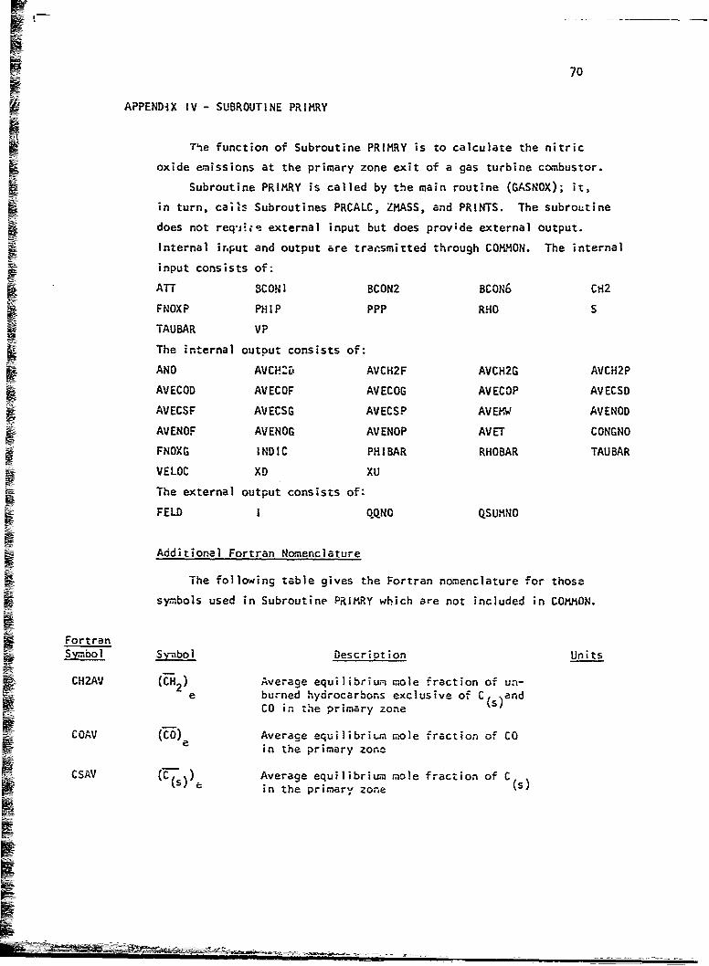
Inc;70
W APPENDIX IV - SUBROUTINE PRIMRY
ý The function of Subroutine PRIMRY is to calculate the nitric
oxide emissions at the primary zone exit of a gas turbine combustor.
Subroutine PRIMRY is called by the main routine (GASNOX); it,
F- in turn, cafls Subroutines PRCALC, ZMASS, and PRINTS. The subroutine
does not req'Jit external input but does provide external output.
Internal input and output are tran•smitted through COMMON. The internal
input consists of:
ATT BCONI BCON2 BCON6 CH2
FNOXP PHIP PPP RHO S
TAUBAR VP
The internal output consists of:
ANO AVCH-5 AVCH2F AVCH2G AVCH2P
AVECOD AVECOF AVECOG AVECOP AVECSD
AVECSF AVECSG AVECSP AVEMW AVENOD
AVENOF AVENOG AVENOP AVET CONGNO
FNOXG INDIC PHIIBAR RHOBAR TAUBAR
VELOC XD XU
The external output consists of:
FELD I QQNO QSUMNO
Additional Fortran Nomenclature
The following table gives the Fortran nomenclature for those
symbols used in Subroutine PRIMRY which are not included in COMMON.
FortranSymbol Symbol Descriotion Units
CH2A'j (CH) Average equilibriUm mole fraction of un-2
e burned hydrocarbons exclusive of C andCO in the primary zone
COAV (CO) Average equilibrium mole fraction of COin the primary zone
CSAV =(C-r) Average equilibrium mole fraction of Cs,e in the primary zone
TI••...

1 711Fortran
S __ ___ Description Units
DELX -X Increment of the combustor length across7which the solution is generated cm
_FELD(I) (P.ac. Element i mass fraction
FN0XG [NO formed in the flame front (mass fraction)
I Index of the element
NPRINT IndicatorNPRINT = 0 ;f irZermediate output is notrequested by tie userNPRINT = I if intermediate output isrequested by the user
j QQNO(I) Nitric oxide cozacentrdtion ih the elementi ppm(vol)
QSUMNO(I) :D-m The cumulative sum of the NO formed up toand including the element i lb/sec
SUMCHIc 1_CH-m Sum of the elemental mass flow rates timestheir respective unburned hydrocarbon(exclusivt of CO and C () equilibriummole fractions gm/sec
SUMCOI :CD-m Sum of the elemental mass flow rates :imestheir respective CO equilibrium mole frac-tions gm/sec
§ SUMCSI - Sum, of the elemental mass flow rates timestheir respective C(s) eauilib. ium molefractions gm/sec
fSUMU'N0I Sum of the elemental mass flow4 rates timestheir respective NO mass fractions gm/sec
SUiT{ I:7- tn Sum of the elemental mass flow rates timestheir respective adiabatic flame tempera-tures qn-d,!g K/sec
An. ysis Procedure
The step-by-step procedure of Subroutine PRIMRY is given below
The Fortran listing of the subroutine is presented at the conclusion of
I

72
1. Convert (NOo) to [NO] by
[NOj (No )-*lo6*1 62. Set the values of XU, X , and &X as:
s XU = 0.0
SxD = 0.0• a x - 0.0
S3. Using Subroutine ZMASS, calculate the mass in each element,
the mean mixture ratio, the airflow, and the total mass
flow.
4. Calculate a*:
Step 5 is performed if V P 0.0p
5. Go to step 8.
6. Calculate V as:p
7.' Go to step 9.
8. Calculate ;7 as:
9. Calculate [NO.e as:
Seach element ~ inte dsrbuin
10. Using Subroutine PRCALC, calcul~ate the NO concentration in
each element in the distribution.
Step 11 is performed only if intermediate output is requested
by the user.
II. Write the heading identifying the primary zone-elemental
exit conditions.

73
12. For eachý element in which m. is non-zero, calculate
"""I -'n and as:
:5 N-0-"
C L
Step!; 13-14 are performed only if ipterm~ediate output is
I ~ requested by. the user.
13. Convert the units of =_NO-m fro /sec to Ib/sec.
14. Convert the units of [NO,] from mass fraction to
i ppm(vol) - m-mole
9M15. Celculate "R03O , , and Rý as:
Steps 16-17 are performed only if intermediate output is
requested by the user. qm-mole
16. Convert the units of [NW.m from ppm(vol) -bgm s o
ppm(vol) .ii 17. For each element in the distribution, write the element
mass fraction, the nitric oxide concentration (ppm-vol),
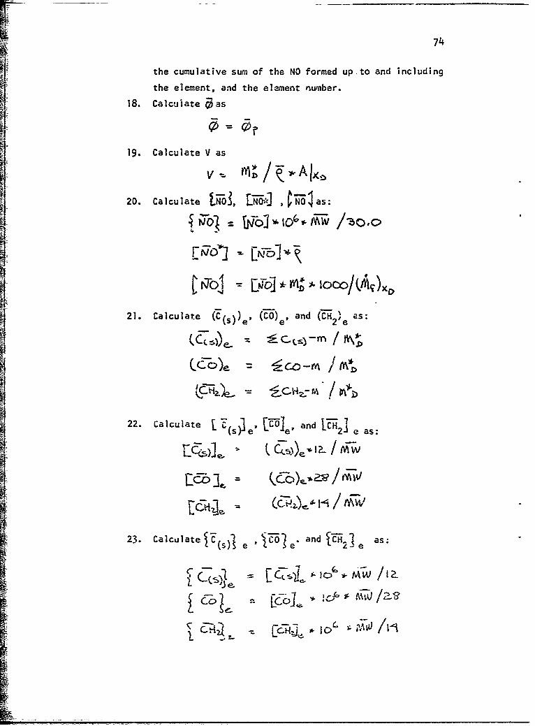
74
the cumulative sum of the NO formed up.to and including
the element, and the element number.
18. Calcuiate 0 as
19. Calculate V as
20. Calculate NO3 J N CFO I as:
21. Calculate (S))e, (CO)., and ('•22e as:
2.C lcu e - e
[•]c -o6-o..e)•"22. Calculate --JI - ....(spe e' n 2J e as:
23. Calculate J$Cs e !o e and C2e
er % L-e as
j1 Co[ 6 J-A~)a

75
24. Calculate [CE !To*]. andECH2J- as,
-i
25. Calculate (S ~ e n ~C 2 eae'.-L e, ad 21W / as
26. Using Subroutine PRINTS, write the output for the primaryI zone.27. Return.
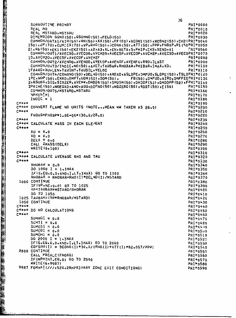
76SUBROUTINE PRIHiRY PRI*0000
REAL NOPRI*00l0REALMSTA~qMSARUPRI*0020
2),R6C50),EK1(50),EK2C50),A2gA3.XLCN,8ETASPHiIP,'ýKSXENDtAI '-RI*0060COMMON/OUTI/AVECSGAVECOG, AVCH2GtAVECSPAVECOP, AVCH2PAVECSDAVECOPRI0 007O
10 DAVCi12OAVECSFiAVECOFoAVCH2F PRI00080COM4MON/OUT2/AVENOGAVENODAVElN0PAVENOF.AVENFURROILAST PRI00090COMMUN/OUT3/INOICNO(50) ,AVETTAU8ARRHOBARPHIBARI'4AXX~s PRIO0100JFS3ARDIXUOLENTAUINTTAUDILVELOC PRI00110COM*0N/OUT4/CONGNO(50) ,DELMl0(50) ,AREADASLOPEDMFUOSLOPE (50) ,TSLOPRI*O'AeO1PENOP(50),EKKDDMFTUDMCSO),DDM(50), FB(SO),ODMFUDAIRogOMFFEOPRI*01302,RSUt3XSIGSIGZERAVEMWDMDDA(50) ,OMUDM(50) ,ON)DP (53) ,OMDDPP (50) ,FPRI*01403PRIME(50),NOEQXDANOAQ0,OIFNO(S0),NOZERO(50),RDOT(50)sE(50) PR100150CO'MMON -OUTS/MSTARD,msTARU PRI*O16O'JPRINTI1 PRI*0170INDIC 1 PRI*0180
C****PRI* 0ol9C** CONVERT FLAME NO UNITS 'NOTE***MEAN MW TAKEN AS 28.0) PR100200
C****PRI 0 0210FNOXG=FNOXP*1.OE-Q6*(30.0/28.0) PRI*0220
C****PR 1*0230C** CALCULATE MASS IN EACH ELEo'ENT PR100240
C****PRI*0250XU =0.0 PRI*0260XD =0.0 PRI0o270DELX =0.0 PRI10280CALI ZMASS(DELX) PRI*0290WRIIE (6,100) PRI*0300
C****PRI*0310C'***8 CALCULATE AVERAGE RHO AND TAU PR1*0320
C**** PRI*0330RHUHAR =0.0 PRI*0340DO 1000 1 = 191MAX PRI*0350Ii(S*EG.0.0.AND*I.LT*IMAX) GO TO 1fl00 PRI*0360RxOBAR = RHO8AR#RHO (I)*0EL'40(I) /MSTARO PRI00370
1000 CONTINUE ?RIco38oIF(VPNE-0O0) GO TO 1025 PRI*o390JP=TAUBAR*MSTARD/RHOBAR PR1*0400
GO TO 1050 PRI*0410105TAUBAR(=(VP*RHOBAR/MSTARD) PRI*0420
1050 CONTINUE PI03DO NO PRI*0440
C**DNOCALCULATIONS PRI*0450C****PRI*0460
SUMNOI = 0.0 PRI*0470SUMTI = 0.0 PRI'O1480SUMCSI= 0.0 PRI*104i!SUI4coI 0.0 ;RI*o~tioSUMCHI = 0.0 PRI*0 551o00 2000 I = l,!MAX PRIO05 2 0IF(S.ECJ.0*0.AND.I.LT.IMAX) GD TO 2000 PRI*0530COVGNU(I) = BCON6 C )*30.0/ (RHOC I) *ATT (I) 082.0S7/PPP) PRI*054n
?R000 CONTINUE PRI*055CCALL. PRCALC (FNOXG) PRI*0560IF(NPRINT.EQ.0) GO TO 2500 PRI*0570WRITE (699987) PRIO0580
9987 FOR:4AT(///952Xt28HPRI:4ARY ZONE EXIT CONDITIONS) PRI*0590

77
WRITE (6,9988) PRI00600
9988 FORMAl (///,46X,4iKMASS,9X,2HNO,8X,8HTOTAL NOt7X97HELEMEI4T) PR100610WRITE 16.9989) PRI*o620
99R9 Fo~mATC44X,8HFRACTION,5XRl4PPM(VOL) ,SX,6HL8/SEC,1OX,3HN0../) PRI*06302500 CONTINUE PRI*o648
DO 3000 I =1*IMAX PI05
IF(f)ELMOCI).EO.0.0) GO TO 3000 PRI*0660BESUMNOI = SUMNOI*NO(I)*OELMO(I) PR 1 0670SUMCSi = SUMCSI*BCON1 (I)*OE-LMD(I) PRI*0680
SUMC01 =SUMCOI + BCON2(I)'*OELMD(I) PRI*0690SUMC141 = SUMCHI*CH2(I)*DELMD{I) PR1*0700SUmTI SUMTI4aTT(I)*OELMD(I) PRI*0710FELD(I) = DELMD(I)/MSTARD PRI*0720
IFCNPHINT.EQ.0) GO TO 3000 PRI*0730OSUmNO(I) = SUMNOZ/454*0 PRI*0740
QQNO(l) 7 O(I)'1.*3E+06/30*0 PRI*0 7503000 CGJTINJE PRI*0760
AVENOG = SUMNOI/MSTARD PRI*07?0ANO AVENOG PRI*0780
AVET SUMTI/MSTARD PRI*0790
AVEmw =RHOBAR*AVET*a2o057/PPP PRI*0800IFCNPRINT.EQ.0) Go TO 3200 PR -*0810DO 3100 I =19IMAX PRI'I:3--20QQNO(I) = QQNOCI)*AVEMW PRI*0 830
WRITE(6,9990) FELD(I),QQNO(I),QSUMNO(I),I PRI*0 6089990 FOHMAT(42X#3E12*597X9I3) PR 1,0 85
3100 CONTINUE PRI'C6603200 CONTINUE PRI*0870
C***- PRI*0880C*** CALCULATE VELOCITY AND PHIBAR PRI'0890C*** PRI*0900
PHIBzAH =PHI? PRI'0910VELOC =MSTARD/(RHOBAR*AREAD) PRI'0920L AVENOP=AVENOC*'1 .E.06*AVEMiW/30.0 PRI'0930AVENOD = AVENOGORHOBAR PRI'0940AVENOF = AVENOG*MSTARD*10009/DMFT PRI*0950CSAV =SUmCSI/NiSTARD PRI*0960COAV =Sumcoi/I4STARD PRI*0970CH2AV SUMCHI/MSTARD PRI*0960AVECSG =CSAV*12.0/AVEMW PRI*0990A VEcOG =COAV*28.0/AVEMW PRI*1000AVCH2G =CH2AV*14.i)/AVEMW PRI*1010AVECSP=AVECSG*1 .OE.06*AVEMW/12.0 PRI'1020AVECOP=AVECOG*1 .OE.06*AVEMI/28.0 PRI*1030AvCiH2P=AVCH2G*1.OE.06'AVEMO/14.0 PRI*1040AVECbUI= AVECSG*RHOBAR PRI01050AVECOL) = AVECOG*RHOBAR PRI*1060.AVCH2L) = AVCH2G*RHOBAR PRI*1070AvECSF=AVECSG*mSTARDO'100. 0/OMFT PaI'0so8
JAVECOF = AVECOG*MSTARD*1000*//O'4FT PI19AVCH2F = AVCH2G*MSTAROQ1000*/D'AFT PRIo1100CALL PRINTS PRIDI110
100 FOR'MATCIH1) ?RI0112oRETURN PRI*1130END PRI'1140

IT
78
APPENDIX V - SUBROUTINE ZINTER
The function of Subroutine ZINTER is to calcu;•te the -:oncentration
of nitric oxide at specified axial stations, and at the exit, of the
intermediate zone of a gas turbine combustor.
Subroutine ZINTER is called by the main routine (GASNGU): it, in
turn, calls Subroutines MINT, CHECKK, RUNKUT, ZMASS, and PRINTS. Thesubroutine does not require external input but does provide external
output. Internal input and output are transmitted through COMMON.
The internal input consists of:
ATT BCONI BCON2 BCON6 CH2
CN CONGNO EKS EKI EK2
FF LEN NO NOZERO PPP
RHO RSUBX RI R6 TAUBAR
XD XEND XL
The internal output consists of:
ANO AQQ AVCH2D AVCH2F AVCH2G
AVCH2P AVECOD AVECOF AVECOG AVECOP
AVECSD AVECSF AVECSG AVECSP AVEIW
AVENFU AVENOD AVENOF AVENOG AVENOP
AVET CONGNO DvDDA DMDDM DMDDP
D1MDPP EKKD ILAST INDIC LEN
NO NOP PHIBAR RHOBAR RRO
TAUBAR TAUINT VELOC XD XU
The external OLtput consists of:
AVNO AVRHO DDFNO E lIE
J N XD
Additional Fortran Nomenclature
The following table gives the Fortran nomenclature for those
symbols used in Subroutine ZINTER which are not included in COMMON:Fortran
Symbol Svmbo Descriotion Units
AVNO(J) NO. Mass averace nitric oxide concentrationfor a given iteration j at tne end of eachmajor step in the combustor

79
FortranSymboI S.mbol Description Units
"AVRHO(J) Mass average density of the combustion
A products for a given iteration j at theend of each major step in the combustor gm/cc
AVVNG rat, Aatio of total hitric oxide mixing out ofthe elements to the total mass mixing intothe elements
AVVNOG NO Mass average nitric oxide concentration fora given iteration at a given axial step inthe combustor
CH2AV (.H 2 )e Mass average equilibrium mole fraction ofunbur,'ed hydrocarbons (exclusive of C(S and
C)) at a given axial station in the combustor
CNOLST [NO]IK Nitric oxide equilibrium concentration forthe last incremental step in the intermediatezone
COAV (t-) Mass average equilibrium mole fraction of
carbon monoxide at a given axial station in
the combustor
CSAV (C) Mass average equilibrium mole fracti -f C
5 e at a given axial stati'on in) the combustor(S
DDFNO iwN Measure of difference in the calculated NOlevels a-ter successive iterations at a givenaxial station in the combustor
DELTAX &X Integration step size (major) in the inter-mediate zone cm
DELX X Increment of the combuistor length acrosswhich the solution is generated cm
DIFNO [N Measure of difference in the calculatedNO levels after successive iterations ata given axial station in the combustor
DUMJY E Du.n-•y variable
EK *k Constant - equal to 0.05
EKILST (K )LST Ratio of forward reaction rate constantsfor the last step in the intermediate zone
at the mean mixture ratio (see Volume 2, Section 2or Ref 3 )
*Variable initialized but not used in subroutineTi

80
FortranSymbol symbol Description UnitsEK2LST (K2
2 LST Ratio of forward reaction rate constantsfor the last step in the intermediatezone at the mean mixture ratio (see Volume2, Section 2 or Ref 3)
EN N Proportionality constant between &X and X
FFF F Mean mixture ratio for the last step in theintermediate zone
FURAT 14 Measure of change in NO concentration forsuccessive steps in the combustor
GNOMI (NO] Nitric oxide content of an element i at aSgm given axial station in the combustor
lENDZ IndicatorIENDZ = 0 for all except the last majorintegration step in the intermediate zoneIENDZ = I for the last major integrationstep in the intermediate zone
II II Integration increment index
HE Iie Counter of number of iterations attemptingto satisfy E. criteria
J J Number of iterations for each major axii]step in the combustor
K K Number of iterations for each major axialstep in the combustor
KON(I)" IndexKON(1) = 0 if integraz.on for the elementhas not convergedKON(I) = I if integration for the elementhas converged
LSGN IndicatorLSGN = I if intermediate zone and not thelast se? in the zoneLSGN = 2 if intermediate zone and the laststep in the zoneLSGN = 3 if dilution zone
*Variable initialized but not used in subroutine

FortranSymbol symbol Description Urits
N Proportiona :y constant between AX and SX
NOAVGS r spe Nitric oxide concentration of the lastspec element in the array
NONO(I) [NOiINO Dummy variable
NOSTAR " NOI Nitric oxide concentration of the combus-tion products before air addition at a
given axial station in the combustor
NPRINT IndicatorNPRINT = 0 if intermediate output isnot requested by the user
NPRINT = I if intermediate output isrequested by the user
OUTNO (N0o_I Total nitric oxide mixing out of theelements at a given axial station inthe combusto. intermediate zone gm/sec-cm
OUTNO2 N010-2 Total nitric oxide at a given upstreamaxial station in the combustor inter-mediate zone gm/sec
PINO M . Total mass mixing into the elements atin a given axial station in the combustor gm/sec-cm
Q(1) qi Measure of the round-off error for theelement i at a given axial station in
the combustor
QQ(i) qq1 measure of the round-off error for theelement i at a given axial station inthe combustor
RHOLST asT Density of combustion productt for thelast step in the intermediate zone atthe mean mixture ratio gm/cm
RHOMI Du'- Dummy variable gm2/ 1m3
RILST (RI)LST Fowvard reaction rate for the first kineticreaction for the last step in the inter-
mediate zone at the mean -..ixture ratio (see 3Volume 2, Section 2 or Ref 3) gm-mole/cm -sec
!Variable set real but not used in subroutine.

82
FortranSymboI Symbol Descriotion Units
RULST (R6 ) Forward reaction rate for the sixth)LST kinetic reaction for the last step
in the intermediate zone at the meanmixture ratio (see Volume 2, Section 2 or 3Ref 3) g)-mo e/cm sec
STEPS n Number of remaining integration stepst nstepsbefore end of intermediate zone
S STORE 1 Dum�y variable gm-mo1e/cm3 -sec
STORE2 Dummy variable gm-mole/cm -sec
STORE3 Dumy variable
STORE4 Dummy variable
STORE5 Dummy variableSSTORE6 Dummy variable deg K
STORE7 Dummy variable gm/cm3
SUMNOI 14Jo/A Summation of the total nitric oxide presentat a given axial location in the intermediatezone gm
2 3SUMI(J) Dummy variable gm /cm
SUM2(J) Summation of the total nitric oxide presentat a given axial location in the intermediatezone at the jth iteration at that point gm
TAU InT Incremental residence time secS5ec
TTLAST TLST Adiabatic flame temperature for the laststep in the intermediate zone at the meanmixture ratio deg K
X1 XI Integrated length of intermediate zone cm
XXX X Axial position in the combustor cM
XXXX X Distance between upstream end of integra-tion ,nterval and end of intermediate zone cm
YNOLST (NO ) Equilibrium mole fraction of NO for thee LST last step in the intermediate zone at the
mean mixture ratio

83
Analysis Procedure
The step-by-step procedure of Subroutine ZINTER is given below.
The Fortran listing of the subroutine is presented at the conclusion
of the step-by-step procedure.
I. initialize indicators.
2. Initialize I as:t %u
3. Set ke as:
"~ke = 0.05e
4. Calculate X as
yi = XD
5. Initialize CT xl" as:
Step 6 is performed for each potent;al array element satisfying
the criteria I tE i - 50.
6. initialize q. as:
qi=.O x 0
7. Calculate &X as:
8. Calculate X as:
X= XL-XU if intermediate zone calculations end at XL
X = x -x if intermediate zone caiculat~ons end at XE,I END U END
Step 9 is performed only if &'A 1.
9. Go to step 12.
10. Recalculate &A as:
11. Reset the indicator te indicate tnat this is the last major
integration step in the intarmeC;ate zone.
Steps 12 and 13 are perforimed for eacn potential array eienent
satisfying the criteria: £ 4 50
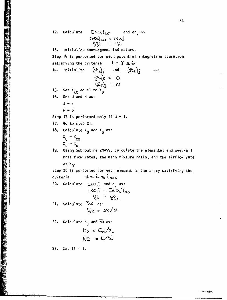
84
12. Calculate EN0.3No and qqi as
13. Initialize convergence indicators.
Step 14 is performed for each potential integration iteration
satisfying the criteria I S :1 tý G114. Initialize and Lg ,as:2C)
15. Set XXX equal to X .
16. Set J and N as:Jm 1
N=5
Step 17 is performed only if J 1.
17. Go to step 21.
18. Calculate XU and X as:SXU = XXXi D v.XU
S19. Using Subroutine ZMASS, calculate the elemental and over-all
mass flow rates, the mean mixture ratio, and the airflow ratei~i at X.
Step 20 is performed for each element in the array satisfying thei ~~~~criteria : - ••
,• 20. Calculate [.:0,'• and q, as:
N:21. Calculate SýX as:
22. Calculate K D and 710 as:
23. Set 1! I
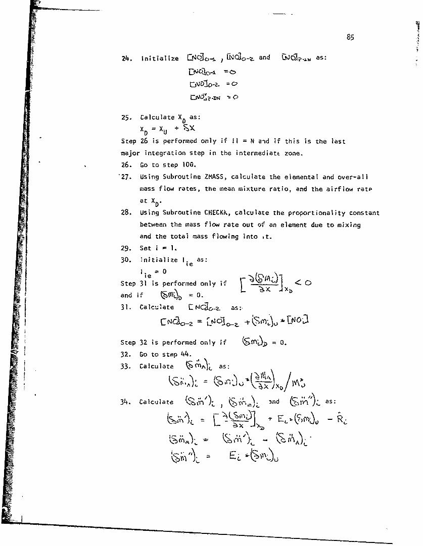
-• 85
24. Initialize {-0. iiNqi10-•_ and iCi1?-.N as:
25. Calculate X as:
x0 = Xu + , YStep 26 is performed only if ii = N and if this is the last
major integration step in the intermediatt zone.
26. Go to step 100.
"27. Using Subroutine ZMASS, calculate the elemental and over-all
mass flow rates, the mean mixture ratio, and the airflow ratp
at XD.
28. Using Subroutine CHECKK, calculate the proportionality constant
between the mass flow rate out of an element due to mixing
and the total mass flowing into it.
29. Set i - 1.
30. initialize ie as:
i. =0
Step 31 is performed only if LC>0
31. Calculate - as:.
Step 32 is performed only if A,= 0.
32. Go to step 44.
33. Calculate as:
34. Calculate L iL n 3nd >as:
i j
/-r
A)

t 86
Step 35 is performed only if v 7Q
35. Go to step 43.
36. Calculate E. as:
E. = 2Ei
Step 37 is performed only if Ei 0..
37. Calculate E, as:
E. -0.02
"38. Calculate I. as:1.=i. +l
lie ie
Step 39 is performed only if lI e h40.39. Go to step 34.
S40. Write 1. and E..ie
41. Reset the appropriate inuicator to indicate that inter-
mediate zone calculations end at XEND'
42. Go to step 125.
43. Calculate CN0"10_1 and Alxg as:
M0~ [:N6] 3 0 L*E-J-
44. If this is not the last element in the array satisfying
the criteria I -- - h• increment i as i = i + I
and go to step 30. If this is the last element, go to step
45.
45. Calculate ENO'20-1 as:
46. Calculate rat 1 as:
47. initialize 4j; as;
48. Set i - I.
Step 49 is performed only if b = 0 or if the chemical
rate of production of NO in the element is zero.
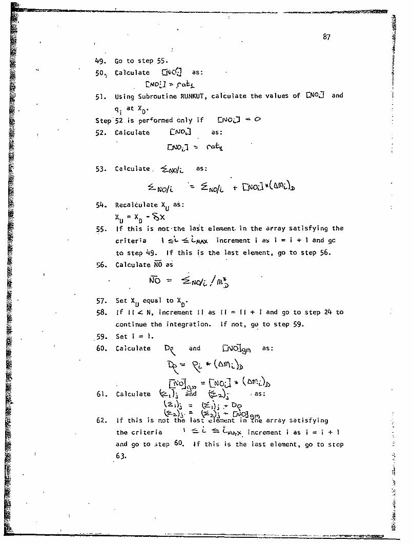
87
49. Go to step 55.
50.. Calculate Gýej'i4 as:
15 51. Using Subroutine RUNKUT, calculate the values of QNOJ and
q at X
RM Step52 is perlormed only if [NO:j 0
52. Calculate as:
53. Calculate. -- OL as:
54. Recalculate X as:
UUS~xu = x0 -D
If this is not-the last element. in the array satisfying the
criteria I --A -'- Lq&0&, increment i as i = i + 1 and ge
to step 49. if this is the last element, go to step 56.
t 56. Calculate NO as
57. Set XU equal to X
58. If IIf N, increment I! as Ii = I + 1 and go to step 24 to
OF- continue the integration. If not, go to step 59.
59. Set i=.
60. Calculate Di and EN61, as:
61. Calculate f:,') and as:
62. If this is not the last element in Lne array satisfying
the criteria I_ L c increment i as i = i + ISand go to itep 60. If this is the iast element, go to stcp
63.BE2
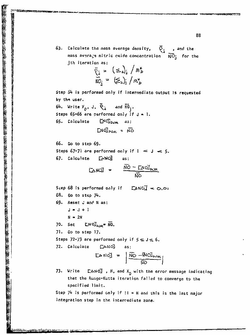
88
63,. Calculate the mass average density, . , and the
mass average nitric oxide concentration NOý for the
jth iteration as:
Step ý4 is performed only if intermediate output Is requested
by th'e user.
64. Write V J and ..Steps 65-66 are performed only if J 1.
65. Calculate .5Z; as:
II 6. Clcuate 1Nc1"a as:Wo
66. Go to step 69.
Steps 67-7i are perforried only if I -- J 5.
S67. Calculate CoN.0 as+:
1 No] = o _2No70. St Uo~h~,= NO
Seep 68 is performed oaly if E:ANQ]• o.oi
68. Go to step 74.
65. Reset Z and N as:
N=2N
70. Set LI J7o%03 io= .
71. Go to step 17.
Steps 72-73 are performed only if 5-J•--6.
72. Calculate F as:
i~o- U4 a73. Write -AtN01 , N, and XD with the error message indicating
that the Runge-Kutta iteration failed to converge to thespecified limit.
Step 74 is performed only if !I = N and this is the last major
integration step in the. intercediate zone,
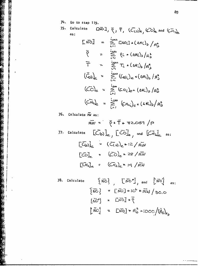
89
74. Go to step 119.75 Calculate jj c.{ (b and
as:
I/,
t<. c- o CIe (a 'O /mD
76. Calculate iW as:
ii
~I W
78. Calculate and as:
E -6
- ji IC • /(.ji, _
If

90
79. Calculate and j and as:
80. Calculate C ) L-Y - a ndsas:
CI
C~Fol-e Z•I81. Calculate s: and as:
82. Calculate as:
83. Calculate n step as:
Step 84 is performed only if ( ,
8k. Set the appropriate indicator to indicate that the nitric
ox;'•a reaction is frozen at this point in the combustor.

91
85. Calculate 'n. as:
86. Calculate -nt and It as:
87. Calculate Vas:
88. Calculate as:
89. Using Subroutine PRINTS, write the output for this axial
station in the intermediate zone.
Step 90 is performed only if the nitric oxide reaction is
frozen at this point in the combustor.
90. Write a message indicating frozen conditions exist in the
comnbus tor.
Step 91 is performed only if the appropriate indicator has been
previously set to indicate that the nitric oxide reaction is
frozen.
91. Go to step 124.
92. Set as:
93. Calculate as:
ýO rr I n'
Step 94 is performed only for the last major integration step
in the intermediate zone.
94. Go to step 125.

92
95. Calculate X as:
Xxx X - X if intermediate zone calculations end at X..
XXXX= x'END - XU if intermediate zone calculations end at X END
Step 96 is performed only if A; XXX,
96. Go to step 12.
97. Calculate &( as:
98. Set the appropriate indicator to indicate that this is the
last major integration step in the intermediate zone.
¶ 99. Go to step 12.
100. Set the appropriate ineicdtor to indicate a dilution zone
type calculation is to be applied to the last element in
the intermediate zone.
101. Using Subroutine ZMASS, calculate the over-all mass flow
rate, the mean mixture ratio, and the airflow rate at X0 -
'102. Using Subroutine CHECKK, calculate the mass flow rate out
of an element due to mixing and the tot l mass flowing
into it.
103. Feset the appropriate indicator to indicate intermediate
zone calculat;ons.
104. Calculate Q and ,iJ451jAp as:
105. Using Subroutine .iNT, calculate
106. Using Subroutine MINT, calculate I T
107. Using Subroutine INT, calculate L
108. bIjing Subroutine MINT, calculate
109. Usinn Subroutine MINT, calculate
110. Using Subroutine MINT, calculate
Ill. Using Subroutine MINT, calculate
112. Calculate &-.•z, as:

93
113. Set the appropriate indicator to indicate that this is
the last step of the intermediate zone calculations.
114. Using Subroutine RUNKUT, compute the values of LJAN and
Q at X9.
115. Recalculate XU as:
xU = x
116. Reset the appropriate indicator to signify intermediate
zone calculations.
117. Calculate j and NO. as:
118. Gro to step 65.
1 119. ComputeT ,- and-Qas:
QF0 - =1T)A
120. Using Subroutine MINT, compute (C(S))e-
121. Using Subroutine MINT, compute (CO)e-
122. Using Subroutine MINT, compute (5d 2)2e
123. Go to step 76.
124. Calculate £i-oI, as:
j 125. Return.
ii
IJ
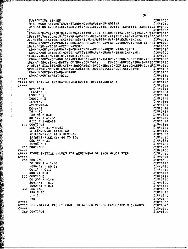
SUtdROUTINE ZINTER 9 ZtNO00000
REAL NONO(5O) ,mSTARU,?4STARON0,NOAVGSN0PsNOSTAR 11N0 0010DIMENSION AVRNO(1O),AVNO(1O)sKON(1O),Q(5O),QQ(50),SUMI41I0),SUH2(1LIN*O'A2O1) LINO6030
150),ZP(70),CU,401S(70),VPRHO(50),BCON6(50)sATT{50h#PPPFNOXPRl(50L1N900502) ,R6(5o) .EK1 (50) ,EK2(50) ,A2,A3,XLCNBETASPHilPEKS1,XENDAI ZINO0O60C04,40N/OUT1/AVECSGAVECOG.AVCH2GAVECSPAVECOPAVCH2PAVECSDAVECOLINO007O
COMMON/OUT2/AVENOG;AVENODAVENOP:AVENOF:AVENFURRO.ILAST ZN09
COHMON/OUT3/INDICNO(50) ,AVETTAUBARRHOBARPHIBARI)4AXXD, ZIN*0100
1P~iOP(0)tKK~DMFtU ,0014OD(50), FB(50) ,OHPUDtAIROOHFFEOLIN0 O1302tRSBX:IG*IGZ~sAENWDMDA(5)tDDDM50,DMO0P(50) ,DMDOPP(50) ,FLINOOI44o
3PRImE(50)sNOEQXDANO.AQQsSUEA(50),NOZERO(50),RDOT(50),E(50) ZIN00150COMMON/OUT5/MSTAROMSTARU LI N4 0160COMMON/OUT6/REAT90ILL LIN90170
C**** ZINO,0iROC**** SET INITIAL INOICATORS9CALCULATE DELTAXtCHECK X LIN'0190C**** Z1N00200
NPRINTzo Z1N*0210ILAST--0 ZIN*0220LSGN = 2IN0 0230INDICE LI N90240IENOL=O ZIN00250AVENFUJo.o 11N*0260
7K=0*05Z1N*0270XU zAD Z1N9 0280TALJINT = 0.0 ZIN0 0290DO 100 I =1,50 ZIN*O3000(I) =1*0E-15 L1N*0310
100 CONTINUE LI NO0320DELTAX = o.1'RSUBX Z1N*0330IF(LEN.EQ.O) XI-XL-XU Lr N9 0340IF(LEN*EQ.1) XI =XEND-XU ZIN00350IF(DELTAX.LE.XI) Go TO 200 ZINVOS.60DELTAX XI L1N00370IE1401 1 ZIN*03z0
200 CONTINUE zi.N*0390C****LI N*0400
-C**" STORE INITIAL VALUES FOR BEGINNING OF EACH MiAJOR STEP ZIN00410Coo** ZN*0420
250 CONTINUE ZIN 9O'30DO 300 1 = 1950 LI 0 04 40NONO(I) = NOII) ZIN0045000(1) =0(I) Z%06KON(I) =0 LI N~q4?0
300 CONTINUE ZIN0 048 -D0 350 K =196 ZIN-0490SU'41(') = 0.0 ZINofl500SUM21K) = 0.0 ZIuno51o
350 CONTINUE LIN90520XXX 3AD ZIN0OS30J = LjN~00540N=5 Z1N00b50
ZIN~OD60co,-* SET INITIAL VALUES EQUAL TO STORED VALUF-S EACH TIME N CHANGES L!N*0570
C**21 ZIN05 90360 CONTINUE LIN*0590

IF(JiEQ.I) GO TO Zi. 1.., - L Jl6 j00xij = Xxx LIN005iO
~ ~.iFIUOPMiID FOR CALCULATION OF SLOPE:in~o64o
CAU L~mASySJLX L!E6D6 4Cý I = isdmAX z IM0670
011 Q0O,17 1pJ00690400 CONTINU-:ZN~O
D &X DLTAX/Eh I," 0 7 21
EKXQ=;;f,";LL! 'aIN* 7 3 0AOUN3ryO2O.'-ý ZI-NOOBD
DO 3000 .AND1IENZlEQmi) O TO 800
CALL LAASS(DELX) ZIN008340CALL CHECKKCOELXI )005
COO** IN~bE50
C*** 0A(1 = UiN0oSLOE/ST0
C* O(I=M***I-NDAI ZILN*0890
j~D 20IELT4)GOT 00 L1lIKA Zi4107IIT~E= ;999 IIIIEE!L)3IFSOET)LEN1-ADDM(~EQ00 0f42TO*DXt.Nil; ?~ago1lFOMI.Qa0 60 TO 20C0
0uTROuTN0.O=MOI)*DM(I) LiNO (I?
CO**" CUN#HENCE E()ZNO QA EOZ!N0104oC**** OJTNOOUTNO/OEL
&O 40U0IJ1,S4 Z1N~1103I=F(001(1.*E.040) GO TO 4600 L.011c;
xRTI;S9)IEEI
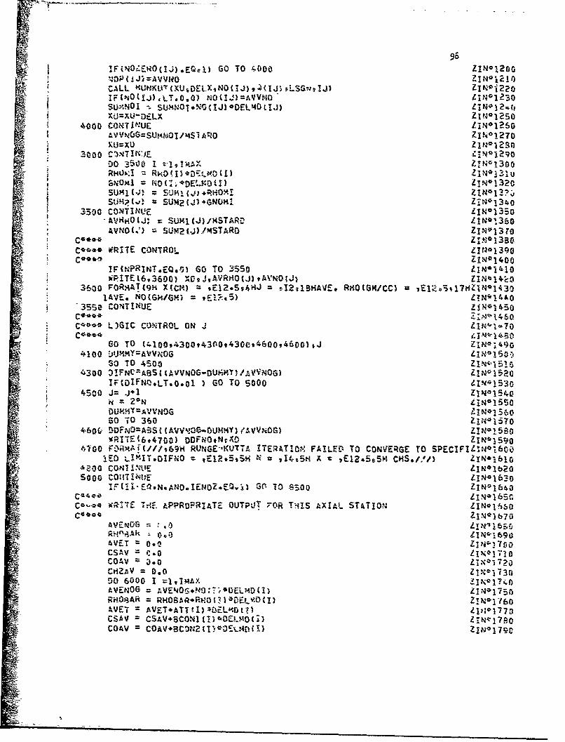
96NItFvi-EROdj.)E~cl 60 TO &,0O00Z~I0
'43 IJi AVVUO INa1CALL ~LNU{t~EXN~J ~Z~.Sn!)ZN1?IFiNO(IJ),LT.0.0). NO Q .)=AVVNO tiN*1230SU9NOI -. SUMNO1.%'43jIJ)*@OEL~40(IJ) LIM*12*(iX-j"XU!DELX Z I N01250
4000 CONTINUE liN*1260'VVNtGGSUlAMOI/1Si ARO Z IN0~1270
ýU~xuz1N 91230Io 300c0 r~T I~ _ZN
GNOM4I IZ(DL10I IN*1320
3500 CO'NTINL!E N*35
AVNO~t') m2j/SADZN10
C**** WRITE CONTROL ZINO1390
IFCNPRINT.Eo.ol Go To 355o ZIN*14608WITE(6*3600) og.j,AVRHO(J)vWA%'N0jJ t-k1N4'l'I
3600 FOR,4AB(91 X(CM vE12*5v4HJ -4-2zl8tiAVE* RHO(GH/CC) iE2v3lUz~l3lAVE.* NO(GM/GM) 9E!,c~5) I140
'3550 CONTINUE zimo ~s0
C4o L)GIC CONTROL ON J
60 TO C4l00,4300,4300,t4300,4600,4600) tJ ZIN-14904100 DUMiMY=AVVNOG LIN-1l3.
SO TO 4500 zi%-15is4.300 OIFNC=ABSI IAVVNOG-OUi;PWT)/AVVNOG) ~NI2
I&F(DIFNO-LT.O.ol ) 6O To 5000 ZI.'N*153o
N2~N t1N*1550
DUMMY AVVNDG zzmol 5606O T0 360 li -44N170
400 CON1I4 v9 RNEKUT TRAINFALý- OCNERET SEIIEN10
4200 COIITINIUE LN1
IFlEQ-N*AUD.IEUOZ*EQw!%# G(' 7O 8300 ZIN01640
Co Q* W;'TE T!*~. kPPROPRIAT-7 OUTPUT 7OR ThI1S AXIAL- STATIOnJ Li N I 65
LIN-16so
AVETO = .0 zw10CSAV =C.0 LI- ,IT1
COAV = 0.0 li%1720cm2AV = 0.o Zixo-73000 6000 1 =10M~AX -N14AVENOG AVEN4OG*?40:TF'fDEMDtI) z.,15RH08Ak RHOSA ARFO t) *D0Ew vD 1) I*16AVET =AVET*ATTtI!*0ELo.rj!,) Z:1CsAv = CSAV~so.IBC ID 4,OEL.O (i3 ZIN~rj7aoCOAV =COAV+3C0N2(u.-0%Ar-L4rDiI Z1Nm1790
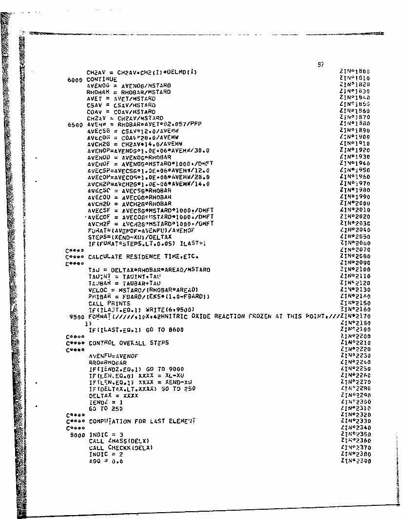
CH2AV =CJ4?AV4CH2(vI)OI0LMDCL Zbia6000 CONTINUE IP'~
AVf)4OG AVENOG/MSTARDRHOsAH RHOBAR/MSTARO 1N06-AVET = VET/94STARD I~ 4CSAV =CSAV/l4STARO L' N=i8COAV =COAV/MSTARD ZIN01860c42~v -CH2AV/m.STAQ ZuRO)~
6500 AVEIQI RHO8AR*AVET*02-057/PPP LIN-138AvEcSG = SV1./V~ ZINOI890AVtCO6 = COAVP2890/AVEMWk ?;N*IgooAVCII2G =C2Vj,/V-WZN11AVEN4OP=AVENOGO! OEiO6*AVEMR/30.0 ZIN*1920AVEN0i) = AVENO4G*Rm.OBAR ZIN*1930
AVErNOF = AVEN6G~4H5TARO1 000 ./DMFT ZN14iiiAVEC5P=AVECSr,*1 3E.06*AVE,4I/12,0 1I",*I950AvECO'P=AVECO'q.1.OE.06*AVEHVW/28* o ZIN01960AVCrI2P=AVCH2G*I -0E-06*AVE,4W/14.0 ZIN01970AvCVcCf = AVECSG*RHOBAR Z1NO1980AVECOOD AVECOGGRHOBAR Lii 99AVCH2LJ = AVCH2G*RHOBAR N*20
AYECSF =AVECSG#I4STARDOIUOO*O.MFT ZN21-AvECOF =AVECOGff!tSTARO'1000*/DI4FT Z!N*2020AVCH2F = 01.i6,1SAD 00+/m ZIN*203CFiJRAT=(AVr-'0OF-AVENFU) /AVEN,40 LINOZA40STcP5=(XENO-D'XU /OELTAX LIN*2ov50IF(FURATzb-TEPSLT.0.05) ILASTvj ZIN*2-060
co~t** IN*2070Co*** CALCULATE: RESIDENCE TIP-EtETC* I*28
TAU DELTAX*RHO8AR*AREA0/MSTARO ZN20TAUIN.T =TAUINT.TrAt ZIN*E1 10
T.IM =TAUBAR*T'AU ZINC--,10VELOC =MSTARD/(RHiOSAROAREAO) Z:IJ*2130PHISAR =F9ARD/(EKS*(1.0-F8ARD)) ZT *2AoCfLL PRINTS Z I 0 150if(TLAC!T*EO.3) WRITE(6995O009 3IN*160
9500 FORMAT(/////v1(VX942HNITRIC OXIDE REACTION rR0ZEh AT' THIS P0Mg/ZN27
IF(ILAST.EQ.*1) GO TO 8600 Zliu.!2190
1a** Z1N*2200C** CONTROL OVERALL STEPS ZIN-z22O
A'/ENFU=AvENioF Z-'2~ I RO=RmoE.AR ZIN02240
lF(IENDZ.EQ~l1 GO TO 9000 ZIN02250I IFt.LEN.EO.0) XXXX = XL-XU Z I N0 26~C! FfLrN.EO.1) XXXX =XEND-XUZI027I=F{OELTAX.LTXXXX) 6O TO Z50 ~ 2RDELTAX =XXXXIENOL 2- 160 TO 250 1IN'-2310CJS000 INDIC =3'CALL PU!ASSONFORLAS EEM ZIN42360
AQ

AND 0.0 ZIN*2410Do 8100 1 =1,II4AX L1-N*2420AOQQ AOQ.01I)ODELMDtl) LN22
AND =ANO+NO(I)*DELMD(I) ZIN-~2430
8100 FFF =STSAR tIN*2450
C A L * ! t T ( 1 # F, '; * -3 5 *F F o~l o RJP L A S T ) 1 1 N *2 4 8 0CAL INT ~1wvFF . 33 FF, EKI Ea(LAST)LN2
CALL MlNT(1,vFF~35sFF9EKl*EKlLST! LIN*250'0SiCALL mINT(19FFF*3StiF,9CON61YNLS;,"CALL MINT(1,FF-935tFFRHONRHOLS7* £1N0 252fl
CALL MlNT(lcFF7935sFFATT#TTLAST) ZIN-;?530
CNOLST = YNOLST030.0/tRHOLSTO TLAS!Th8?,057/PPP) LIN*2540
STURE22 R6(1) ZIN*72560
STORO = EK:C1) -ZIN*P.570
STOtRE4 =EK2tI) Z I K-2 5: 30
STORý5 =CONGN041) ZINO'P90
STOR~b = AITTI ZIN*2600
STORE7 a RmOiBj ZIN*2b10RJQ Ric RILAST ZIN*72b?R6(l) = R6LAST LI N*2630
EKIWt = EKILST ZIN9264.0
EK211) = EKELST ZIN*2650
RtiOW = RHOLST ZLIN*2660
ATT(15 TTLAST -i*6tIieO%DNGNOC1) =CNOLST Z 1N*2680
ISGN =2 ZIN27900
CALL RUNKUT(XU.CELX,ANO9AOQ~LSGNt1) ZIN*2710(
XU AU-OELX ZN21
Rl~l) =STORFI ZIN02720
SjR6(1) mSTJORE2 LIN*2?4C0
E:'1(1) = STORE3 LIN0214G
EK2(l) =STORE4 L..75
CONGNO(l) aSTORE5 Z1Na2,760
ATT (1) =STGP.E6 ZIN*2ý70
RHOW = STGRE? L1N>276o
AVRH4O(j) R14OLST LI~Na;1900
AVNO(J) ANG ZIN*2800
LSGN M1 ZINO2820
GO TO 3550 LIN*2820
ca-- COAPUTE APPROPRIATE AVERAGES li.N0284.L!-N*28c0
8500 AVET =TTLAST Z IN 02 60'
P.niOBAR =RHOLST Z1NO?S70
AVENOG = ANU O**oCALL !4NT(Q9FFF#35vFF,SCON19CSAV) IN?9
-CALL MlNT(IFFF935,FFqSCON2fCOAV) LINO?900
CALL MlNTt1,FFF%3S*FFtCti2,CH2AV) LIN02916
30 TO 65600 ~9999 FONM~A! (IOX9169SE12.5) LIN'293-3
8600 LIND=AiVENOG l*24
9000 RETUR~N z11N 4?950
END 11N?.960

99
APPENDIX VI- SUBROUTINE DILUTE
The function of Subroutine DILUTE is to calculate the concentra-
tion of nitric oxide at specified axial stations, and at the exit of
the dilution zone of a gas turbine combustor.
Subroutine DI!LUTE is called by the main routine (GASNOX); it, in
turn, calls Subroutines ZMASS, MINT, RUNKUT, and PRINTS. The subroutine
does not require external input but does provide external output. In-
ternal input and output are transmitted through COMMON. The internal
input consists of:
AIRD ANO AQQ ATT BCONI
BCON2 BCON6 CiH2 EKS EKI
EK2 FF ILAST PPP RHO
RSUBX RI , R6 S XEND
XD
The internal output consists of:
ANO AVCH2D AVCH2F AVCH2G AVCH2P
AVECOD AVECOF AVECOG AVECOP AVECSD
AVECSF AVECSG AVECSP AVEMW AVENFU
AVENOD AVENOF AVENOG AVENOP AVET
I ND i C NOEQXD PHIBAR RRO TAUBAR
TAUDIL VELOC XD XU
The external output consists of:
DDIFNO DILL DNO J N
REAT RHOBAR XD
Additional Fortran Nomenclature
The following table gives the Fortran nomenclature for those
symbols used in Subroutine DILUTE which are not included in COMMON.
Fortran
Symbol Symbol Description Units
AIRXX M4 . Combustor airflow at axial station X D gm/sec
DDIFNO 11-01 Diffuence in NO concentrations for suc-cessive iterations at the e'id of eachmajor step in the combustor

100
S, FortranSybol rSvr.boI Descriotion Units
DELTAX AX Integration step size (major) in thedilution zone cm
DELX %X Increment of the combustor length across"which the solution is generated cm
DNO £NO)N Average NO at given axial station (down-DN stream) in the combustor
DUMMY [NO01 Dunny variablc
EKILST (K )LT Ratio of forward reaction rate constantsI Lat a given axial station in the dilution
zone at the mean mixture ratio (see Volume-2,Section 2 or Ref 3)
EK2LST (K2)LST Ratio of forward reaction rate constantsat a given axial position in the dilutionzone at the mean mixture ratio (see Volume. 2,Section 2 or Ref 3)
EN N Proportionality constant between W ands.X
FURAT &146NO3, Measure of change in NO concentration forsuccessive steps in the combustor
IENDD IndicatorIENDD = 0 for all except the last majorintegration step in the dilution zoneIENDD = I for the last major integrationstep in the dilution zone
11 11 Integration increment index
J J Number of iterations for each major axialstep in the combustor
LSGN IndicatorLSGN = I if intermediate zone and not thelast step in the zoneLSGN - 2 if intermediate zone and the laststep in the zoneLSGN = 3 if dilution zone
N N Proportionality constant between &X and)X
J NONO ITOJNQ Dummny variable
- 0

101
FortranSymbol i0ool Description Units
NPRINT IndicatorNPRINT = 0 if interme~iate output is notrequested by the userNPRINT = 1 if intermediate output is re-quested by the user
Q q measure of the round-off error in the Runge-Kutta integration routine at a given axialstation in the combustor
q qq Ae:.sure of the round-off error in the Runge-Kutta integration routine at a given axialstation
R1LST (RI)LST Forward reaction rate for the first kineticreaction at a given axial position in the
dilution zone at the mean mixture ratio 3(see Volume 2, Section 2 or Ref 3) gm-mole/cm -sec
R6LST (R6)LST Forward reaction rate for the sixth kineticreaction at a given axial position in the
dilution zone at the mean mixture ratio (see 3"*Volume 2, Section 2 or Ref 3) gm.-mole/cm -sec
STEPS n Nunbe. of remaining integration Lteps be-step fore combustor exit
STOREI Dummy variable q•-nole/cm3-sec
. 3STORE2 Dummmy variable gm-molticm -sec
STORE3 Du.-rry variable
STORE4 Durany variab!e
TAU lnc Incremental residence time sec
YOZ X&Z Distance between upstream and of inte•,a-tion interval to combustor exit cm
XXX XXX Axial position in the combustor cm
XXXX XXXX Distance between upstream enJ of integra-tion interval and combust.,r exit cm
YCH2XD (CP ) Equilibrium m-le fraction • unburned2)eXD hydrocarbon (exclusive c,.- and CO)
at a given axial station in t e dilutionzone at Lhe mean mixture ratio
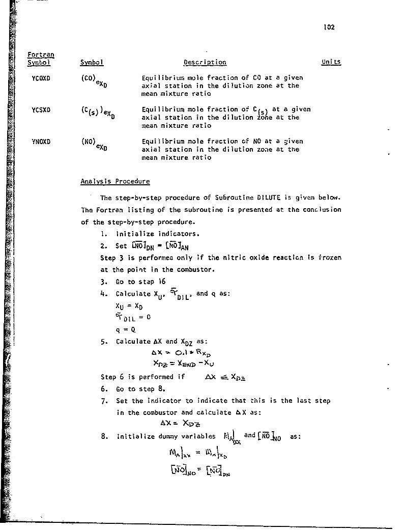
102
FortranSymbol Symbol Description Units
YCOXD (CO)ex Equilibrium mole fraction of CO at a givenaxial station in the dilution zone at the
mean mixture ratio
YCSXD (C~s) )ex Equilibrium mole fraction, of. Cs, at a givenSeaxial station in the dilution SUe at the
,nean mixture ratio
YNOXD (NO) Equilibrium mole fraction of NO at a giveneXD axial station in the dilution zone at the
mean mixture ratio
Analysis Procedure
The step-by-step procedure of Subroutine DILUTE is given below.
The Fortran listing of the subroutine is presented at the conclusion
of the step-by-step procedure.
1. Initialize indicators.
2. Set IRO'DN - IWO]AN
Step 3 is performea only if the nitric oxide reaction is frozen
at the point in the combustor.
3. Go to step 16
4. Calculate XU, 1:r DILD and q as:
XU = XD
"31'DOIL = 0q Q
5. Calculate AX and XDZ as:
Step 6 is performed if AX &
6. Go to step 8.
7. Set the indicator to indicate that this is the last step
in the combustor and calculate bX as:
A "'A Xv s
8. Initialize dummy variables M1 and [W1 as:
V% A\ 1
o L .lN U
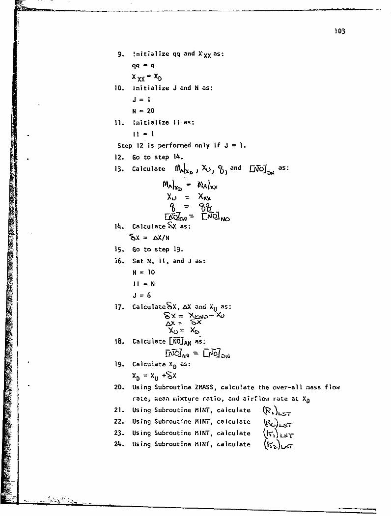
103
9. !nitialize qq and XXX as:
qq = q
X XX = XD
10. Initialize J and N as:J= 1
N =20
11. Initialize II as:Ii =
Step 12 is performed only if J = 1.
12. Go to step 14.
13. Calculate ,, ) and -q0J as:
14. Calculate X as:
'& = AX/N
15. Go to step 19.
16. Set N, ii, and J as:
N =10
J =6
17. CalculateSX, AX and XU as:
AX•- •XSIX- = ev.>
18. Calculate [-0JAN as:
19. Calculate XD as:
XD = XU +%X
20. Using Subroutine ZMASS, calcu!ate the over-all mass f1cra
rate, mean mixture ratio, and airflow rate at XD21. Using Subroutine MINT, calculate
22. Using Subroutine MINT, calculate
23. Using Subroutine MINT, calculate
24. Using Subroutine MINT, calculate O.r.)
-Tt-.- ---.---- _

104
25. Using Subroutine MINT, calculate
26. Using Subroutine MINT, calculate
27. Using Subroutine MINT, calculate
28. Using Subroutine MINT, calculateK2. Using Subroutine MINT, calculate (C.)ex
29. Using Subroutine MINT, calculate (Ci4XI'30. Using Subroutine MINT, calculate (04_z~e~c
Steps 31 and 32 are performed only if the nitric oxide
reaction is frozen at this point in the combustor.S131. Calculate LN'OIDN as:
t~
32. Go to step 38.ii 33. Calculate LN- as:
34. Using Subroutine RUNKUT, cakulate the value of [N-JDN
and q
SSteps 35 and 36 are performed only if II<N
35. Calculate 11 = ii + 1
36. Return to step 20.
Step 37 is performed only if intermediate output is requestedS~by the user.1o and J.
Steps 38 and 39 are performed only if J = I
38. Calculate ENOIDUM
39. Go to step 43.
Steps 40-42 are performed only if l<J-.5.
40. Calculate ,?CN. as:•. •..-, .3 1 ..
- Step 41 is perforned only if - 0.005.
41. Go to step 48.
42. Reset i-gol.., as:
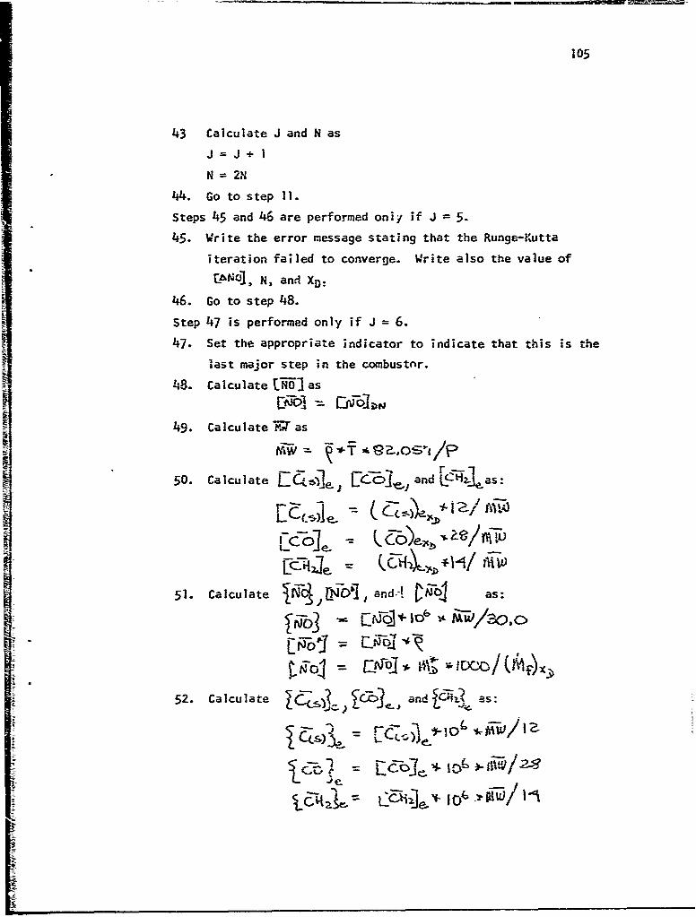
105
43 Calculate J and N asJ=J+1
N 2N
44. Go to step 11.
Steps 45 and 46 are performed oniy if J = 5.
45. Write the error message stating that the Runge-Kutta
iteration failed to converge. Write also the value of
" �C±N1, N, and XD:
46. Go to step 48.
Step 47 is performed only if J = 6.
47. Set the appropriate indicator to indicate that this is the
last major step in the combustnr.
48. Calculate LN-O0 as
49. Calculate A as
r•
50. Calculate r- e., L .,a . LcU-as:
Fc4- 1.4
L-Coe..
51. Calculate and.! fnŽA as:
52. Calculate: - 2. * as:as

53. Calculate -2'j1,je sLi~eS100
54. Calculate \ bc•,.and e as:
Steps 55 and 56 are performed only if the nitric oxide reaction
is frozen at this point in the comibustor.
55. Calculate P as:
- D
56. Calcula'te as:
¶+-I • i,
57. Calculate c , as:
58. Calculate ViDIL and Or as:
I59. Calcu~fate V as:
60. Calculate c as:
-A

107
61. Calculate --RL, as:
62. Calculate nstep as:
Step 63 is performed only if ( L ~ (sei63. Set the appropriate indicator to indicate that the nitric
oxide reaction ;s frozen at this point in the combustor.
64. Using Subroutine PRINTS, write the output for this axialstation in the dilution zone.
65. Reset R)O as:
66. Reset (-)r as:
Step 67 is performed only if the appropriate indicator indicates
that this is the last step in the dilution zone.
E;. Go to step 75.
Step 68 is performed only if the nitric oxide reaction is frozen
at this point in the combustor.
68. Write a message indicating frozen conditions exist in the
combustor.
Step 69 is performed only if the appropriate indicator has been
previously set to indicate that the nitric oxide reaction is
frozen.
69. Go to step 16.
70. Calculate XXXx as:
XXXx = XEND-X DStep 71 is performed only if Lo Xyc
71. Go to step 8.
I!

108
I•- 72. Calculate htX as:
AX = X XXX
73. Set the appropriate indicator to indicate that this is the
last step in the dilution zon-.
74. Go to step 8.
75. Return.
I,
I

log
SJ4R0UTINE DILUTE OIL*O0000REAL mSTARD,N0.NOEQXD*NONOtM~STARU DIL*0010COMMON/DATAI/hIR(50)uRR(50),XX(SO),FF(50),8C0N1(5O),8CON2C50),CH2(DIL1002015)Z(0gUOS7)V*H(09CN(0IT(0tPtNXiI50LD32),R6O5),EK1(5O),EK2(5O),A2tA3,XLsCN,8ý-TA*S.PMIPEKS.XENDsA1 DIL*0040COM1MON/OUTI/AVECSC.,AVECOG,AVC-H2GAVECSPAVECOPAVCH2PAVECSDAVECODIL*
005010 OAVC"'2O9 AVECSF,AVECOF9AVCHi2F D:L*0O60CýOMMON/OUT2/AVENOGAVENODAVEN0PAVENOFAVENFU.RROILAST DIL*o00?COMMON/OUT3/INDICsNOCSO) ,AVETTAUBAHRHOBARtPtIIBAR,134AXXO, DIAL 0 00BO
1Fi3ARDXULENTAUINTTAUDILVELOC OIL*0090P I ~COIMMUN/OUT4/CONGNO(SO) ,OELM40(50) ,AREADASLOPEDMFU0,SLOPE(50) ,TSLOD!L*01001PENOP(501,EKKDDHFTUDHLSO),DDM(S0), Ft3(50),DMFUDsAIRDOMFFEDDILO01102,RSUd~,SIG,SIGZERAVEMWDMDDA(50) ,DMDDM(5O) ,0HD~iOPl5eDMDDPPC5O) ,FDIL*0 12o3PRimE(50),NOEQXDANOAQODIFNO(50),N0ZER0(50),qDOT(50)tE(50) DIL*'0130COMMON/OUTS/,4STARD ,msTARU D1L00140COMMON/CUT6/REAT tDILL D)IL00150
INITIA DIL*0160C**SET ITALINDICATORS, CALCULATE DELTAX* CHECK X DIL00lTO
DIL*n1BONPiRINTro DIL*0190LSGN=3 01 L*02001N01C=3 DIL*0210
£IENODO= DIL*0220IF(s.EQ,.o0) ILAST0 DIL 00230oDNO ZAND DIL*0240IIF(ILAST*EQ.1) GO TO 2000 DIL*0250
TAUDILO * 0 D1L*0270I 0=AQQ DI L* 0280DELTAX=Oo* 1RSUBX DIL*0290XDZ = XEND-XU DIL*0300IF(DELTAX.LE*XDZI GO TO 200 DIL00310DELTAX =XDZ DI1L00320I END1~ DIL~n330
200 CONTINUE DI L* 0340C**** IL*0350
C**** STORE INITIAL VALUES FOR BEGINNING OF EACH MAJOR STEP OIL00360Coo**DIL*0370
250 CONTINUE DIL-03ROAIRXX AIRD 01 L*'0390.IN0ONO DW LIL*0430Q000 DIL*0410XXX XD OliL 00420Jl 1 OL*C¶,30
DDIFNO = 0.0 D!Lc*0450CO* 0IL*0460
C*0 SET INITIAL VALUES EQUAL TO STORED VALUES EACH TIME N CHANGES DTLýý0470
300 11=1 DIL00490lFtJ*;r.O"i) 6O TO 400 DIL'-0500AItRD = AIRXX OTL'051-0
DNO =NONO 01L*ý540400 EN=N DL35
DELX=DELTAX/EN 01 L* 0550Coo** 0IL*O057O7
C** START THE MAJOR STEPS DOWN THE COX.&USTOR DIL*0580coo** DL*0590

S0O TO1 250OIL*0600
J=6 OTLOO630DELXXEND-XD DILvO6400;ELTAA=OELX LD!L*0650Xii=XD 01 L~0660
ANO=DNO DL*067025o0 DO 3000 !I1=1N DIL*0680
XD=XLJODELX OL09CALL ZHA'SS(OELX) DIL'0700
cc@ CALCULATE NO AT XD I*02C04ZJ;01 DL*O730
CALL H'INTi1,P8ARi),35tFFsR1,RlLsT) DIL*0740CAL~L MINT(IPSARO,359FFR6*R6LST) 3i L1075oCALL iiINl(19FBAROv35*FFqEK19EKlLS') w1L*0760
CAL INT(1;FBAPDs35vFF9EK~vEK2LST)0 L*70CALL MI-NTCJyFBARD,35,FFBCON6gYNOXD) 01 L*0 7BCALL hlNTil9FBARD,35tFFtPHORHOBAR) 0100790CALL -MXNT(1,)F8ARO,35,FF,ATT9AVET) DIL4111080CALL -i1NT(1,P8ARD,35,FFsBCONlYCSXD) D0IL*OblcCALL MINT(l1,FBARDt35vFF,8C0N2,YCOXO) D1L*0820CALL MINT:1,FEýAR0,35,FFCH2,YCH2XD) OIL*0i330
I~ IAS.E 0 N0=AN0*MSTARU/MSTARD Dl L*0 840IF(ILAST-EQ-til GO TO 4000 0L05STORE! = RlDIL00860STORE2 = R61'DIL'0870STORE3 = K!(1 _)IL*08R0STORE4 = E-20- OIL*0890
R6(1) =R6LST VDIi40*09107K!1,1) = EKILSI D!L*0920
EK2(l) =EK2LST D!L*0930NOErQXD=YNOXD*30.0/ CRHOBARQAVET*82.057/PPP)0094CALL RUNKUT(XU*OELXtONOOLSGN,1) DIL00950
R1%=STOREI U10*0960R1.=STORE2 013L10970
EK1(1: STORE3 0lL*o980EK20I) = STORE4 D1L*0990
3000 CONTINUE DL10C~oov, DL*1010
C~*** WRITE CONTROL DI L01020A~t C*** i)I L* 1030
IF44PRINT.MO01 6 TO 4000 DIL*10404RITE(6935oo) XDsj9RH08ARvDNOREATipDlL' OIL*1050WRITEI6.9997) ODIFNON DL*rf
350 F~'4T~~iX(CM) = E12*S,48J = 41691&AHAVE. RHOCG4/CC) = E12o5tj7H0IL?-10701AVE.. NO(G'./Cm) ,E12,5vxv2El2,5) I~1~
COO** LOGIC CONTROL ON i DIL*I1100CONTINUE 4112
4000 COTIUEaL*116O TC (4100443o0,4300,4300,4'60094800), J a:~ij3
4100 DUMM~Y =D;0o tGO TO 450C DXL*1 ISO
4300 ODIFNO =A3S((DN-0fUMMY3/ODiO) DIL*1160IF(OOIFNO.LT.0+0051 60 TO 5000 DIL01 1-7o
:5 0DUM4MY = ONO D L, 184500 ~j~ IL,*1190
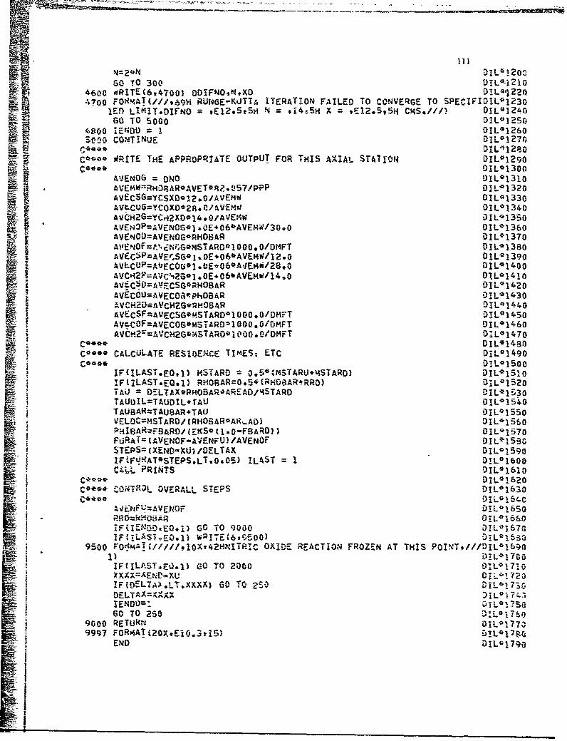
'4=2*N DI11-120:2SO TO 300 OIL*-1210
4600 WRITE(6,4700) ODDFNOtNPXO DIL*4?224700 FOIRMAT(///t-694 RUNGE-KUTTA ITERATION FAILED To0 CONVERGE TO SPECIAFIDIL*1230
lEfl LIAIT-DIFNIO = El2e.SS- =~' #14s5H X = tE12.595iI CMS*/ý/f 01L0 1240GO TO 5000 DIL*1250
4800 IENDDL= I DIL*1260S000 CONTINUE D-012-170
D10'12BOF rcoo* 9ITE HE PPRPRIAE OT~u FORTHI AXAL SA~iu DL*1290
C~*** DIL-T1300P.AT UPU ORTI AILSTTOM L130E_ AVENOG = NO OIL9 1310
AVEMW=R)ý'RAR*AVET*R2. 057/PPP 0AL*1320AVECSG=YCSX0.3l,.0/AVEMW DIIL01330
Kf-AVtC0G=YCOXO*28. L/AVEMJ 0IL0 1340AvC-H2G=YCrA2xo~l4 *0/A VE.4wi IL*i350
AVENO3P=VENOiGOI ,0;E4C6*AVEMW/30 .0 DIL*1360AifENO4F~tNiG*m4STARO01O000,0/OMFT DI L*1380AVECSP=AVEOISG*1 %E0E~6*AVE?4W/12.0 DI L*139oAVLCOP=AVECOfOI~.tEo06*A4EMW/28.0 OIL9 1400
-:AVCI2P=AVC&i2G*1 .0E.06*AVEMW/14.0 DIL*14lnAVýCLAESGROA 0IL0 1420tVEC50=AV=CSG*-WPOBAR OL13
AVECOH2=AVCGr~hOBAR OLAV. -FVCOG~MTR~000DF DIL`i 450
Av~c0F=AVECSG*MSTARD*iO000.0/DMFT DIL*1450
AVCHr=AVCH2G94STA*RO* 10006 /DMFT 0ILO1470
C** CALCULATE RESInXEICE TlmESj ETC D1L*1490C**** IL*15o0
IF(ILASTeEQ.1) MSTARWD = o5(NSTARU.'4STARO) DIL-1510IAF (LAST sEG. 1 RH0BAR=0 .5*(RH08AR4RRO) D01L1520TAU = --LTAX*RHOBAR.'AREAD!4STARD DIL*1530TAIJDIL=TAVDIL. rAU DIL*1540TAU8AR=TAUaAR+TAU D1L*155oVrELOC-=STARO; (RHOBAR*AR".AO) DYL9 ISE60PHI8AR=FBARO/(EKS0(1.G.FBARD)) DIL0157o
SF-URAT%=tAVENOF-AVENFJ) /AVEN0F DIL`ISSOSTrEPS=(XEND-XlU) /OELTAX DIL*1590
?.(FUAT*STEPS.LT.0.05) !LAST I DL0 1600'iiPRINTS D1L*1610
DIL*1620C** C.ONTRZOL OVERALL STEPS DIL'0 1630
C**** OiiL164C
IF41ENUD.ENOF Di)6
lFCIELDi-E:1) GO TO 000 :01L 0-167G
9500 FOj4A7!i///f,1j0Xt42HNITP.ICOID ECIO RZN TTI POINTs///DTL 01b001) .1!L01700
5,I.F(ELTAý'.LTXXXX 0TA2:DELTA=XvXXA L* 7IENDUOl60 TO 250
9000 RETuRN 1-179997 FOR0,ATi20XtEl0.3tT5) DL1~
E14D DLI7
3I1114

k APPENDIX VII - SUBROUTINE PRCALC
The function of Subroutine PRCALC is-to calculate the a~erage
nitric oxide level at the exit of the primary zoie for each mixture ratio
element.
Subroutine PRCALC is called by Subroutine PRIMRY; it, in turn,
calls Subroutine MINY. Subrojtine PRCALC does not require external
input and does not provide external output except for an error message
and diagnostic data table. External output is written directly onto
the outpitatape unit, Internal input and output are transmitted through
CUMQiON and as arguments of the subroutine. The internal input consists
of:
ATT BCONI BCON2 BCON6 C42
' CONGNO DELMD EKI EK2 FBARDFF FNOXG IMAX NOZERO PPRHO RI R6 S
The internal output consists of:
AQQ AVET NO NOEQXD RHOBAR
TAUBAR
The external output consists of:
ALPFA2 DUMMY LIMIT SUMTNO
:1 t ~~Add it ional Fort ran Noir-ncl ature
The foliowin9 table gives the Fortran nomenclature-for those
symbols in Subroutine PRCALC which are not included in COMMON.
FortranSMymo Srnbol D scriotion Units
AAA(|) o0-1 Ratio of NO concentration to NOconcentration at equi ibrium fora mixture element i at the end of theintegration interval
ALPHAO(I) ( OLD ) Ratio of NO Lancentration to NOconcentration at eauflibrium fora mixture element i at the end of theintegration interval

113
Fortran_inbol I Symbol Description Units
ALPHAT(I) (d..)j Ratio of NO concentration toNO concentration at equilibriumfor a mixture element i at. themean primary zone residencetime
ALPHAU(1) (oL)) Ratio of NO conicentration toN3 concentration at equilibriumfor a mixture element i at thestart of the integration interval
ALPHAI Ratio of NO concentration to NOconcentration at equilibrium fora mixture element i 'at 'the start ofthe integration interval
SALPHA2 04-L Ratio of NO concentration to NOconcentration ;at equilibrium fora mixture element i -at the end ofthe -integration. interval
ALPHD-(p•M Ratio of NO concentration to NOconcentration of equilibrium for
"a mixture element i .at'the-end ofintegration interval
ALPHU (0(,)• Ratioof NO concentration to NO con-"I centration at equilibrium for a
mixture element j at the start ofthe integration interval
DALP (A)X Integration interval
DALPHA (Integration intervalIDUMY (I) Du-=y variable
I EKILST (1) L Ratio of for%ýard reaction rateconstants at mean primary zonemixture ratio (Sac Voluime 2, Section 2 or Ref 3•
SEK2LST (I2) T Ratio of forward reaction rateconstants at mean primary zone
: mixture ratio (See Volume 2, Section 2 or Ref 3)EN r integration step size control
ERR - Convergene limit
-FNOXG E-N .Q NO formed in the flame front(mass fraction)*
FT .Fractional mass in an element-hat has a residence time dtabcjt t

114
FortranSymbol Symbol Description Units
P7FTD P Accumulated mass fractionleaving eleaent before -,,"
FTIJ Accumulated masi fractionleaving eleinent before *-j
INDEX Indicator:INDEX - 0 at start ofiterationINDEX = I if convergencecriteria not satisfied
SJ Counter:J-6 if convergence occurson .9--io,
SJ = 6 if converjence limit isnot sat isf ied on •e
SJJ Counter:JJS20 if convergence teston ( appliedJJ720 f? convergence teston : not applied
K Indicator:K = I if first integrationstep
! K 0 1 'Of other than first
integration stepLIMIT InCicator:
LIMIT-IO10 if convergenceoccursLIMIT 10 if convergencecriteria not satisfied
N Integration step size control
REMAIN (1) • Fraction of mass remaining inelement i after convergence criteria
satisfiedRiUST Forward reaction rate for the
first kinetic reaction for anelement at mean primary zonemixture ratio (See Volume 2, Section 32 or Ref 3) gm-mole/cm -sec
R6LST (PLST Forward reaction rate for thesixth kinetic reaction for anelement at mean primary zonemixture ratio (See Volume 2, Section 3
2 or Ref 3) qn-mole/cm sec
STORE] Dummby variable gm-mole/cm -sec
L ..

115
Fortran,Symbol r Description Units
STORE2 Dummy variable gri-moo .e/cm3 -sec
STORE3 DL-my variable
STORE4 Dummy variable
SU$T (i) Sum to time t of the massfractions in an element i
SUMTIO (I) _• . Sum to time t of the productsof the mass fraction and NGconcentrations in an elementi
TD _- Time at ent of integrationinterva ; sec
TIMEN Characteristic time used
to calculate (4I> sec
TT Dummy variable sec
T7S Time at end of integrationinterval ser;
TTUI Time at start of integrationinterval sec
TU. Timn at start of integrationinte.-val sec
YCHZIXD e, x. Equilibrium mole fraction ofunburned hydrocarbons exclusiveof C(s) and CO for an elementat the mean primary zone mixtureratio
YCOXD [•CC.0 e, xb Equilibrium mole fraction of CO foran element at the mean primaryzone mixture r.tio
YCSXD ICIC sle- sýz Equilibrium ra'le fraction of Cfor an element at the meanprimary zone mixture ratio
YNOXD 01e% D Equilibrium mole fraction of NO foran ele meit at the mean primary zoaemixture ratio
Analysis Procedure
SThe step-by-step procedure of Subroutine PRCALC is"given
below. The Fortran listing'of the subroutine is prcsented at the
conclusion of the step-by-step procedure.

116
I. Estimate (;Lz). as:
2. Calculate (•ot) 1 as:
o if OCIC
_ if
Step 3 is performed only if the chemical reaction rate is not
significant.
3. Go to step 10.
4. Using Subroutine PRRA.T, calculate a value of time which
corresponds to the estimate of (o-z)L
5. Calculate a-:
Steps 6 and 7 are performed only if J.•.c471 0.05
6. Reestinmate (04-0"
Step 7 is performed only if the number of iterations on (X(-OL
are less than 10.
7. Go to step 4.
8. Calculate (qXv) .as:
Step 9 is performed only if the number of iterations on
equal 10.
9. Write the value of •LŽ.
10. If this is not the last element in the array, go to step 1.
I]. Initialize q as:
n•= J|0
Step 12 is performed only if C.11) 0.
12. Go to step 50.
Step 13 is perforred only if the chemical reaction rate is not
significant.
13. Go to step 50.

117
14. Calculate (APL);_ and to as:
15. Calculate ( L) as:
Step 16 is perfurmed only if (O.b)L?; 1.0
16. Recalculate (o4D.))L as:
k(-D),- 1.0
Steps 17 through 27 are performed only if SO=O
17. Using Subroutine MINT, calculate tR•).ST
18. Using Subroutine MINT, calculate (N)
19. Using Subroutine MINT, calculate ýVcl)
20. Using Subroutine MINT, calculate (ki)
21. Using Subroutine MINT, calculate
22. Using Subroutine MINT, calculate
23. Using Subroutine MINT, calculate t
24. Using Subroutine MINT, calculate -Cexz
25. Using Subroutine MINT, calculate
26. Using Subroutine MINT, calculate
27. Calculate .ljoe,) as:
•.' "F a~.os--
28. Using Subroutine PRRAT, calculate (OC.D)g.
Step 29 is performed only if Zo= c>
29. Calculate Qas:
Steps 30 through 32 are performed only for the first integration
step.30- Calculate • as:
31. Reset and -to as:
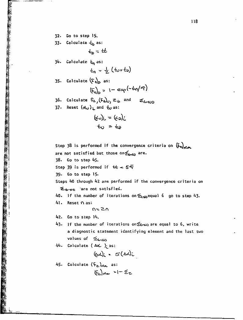
118
32. Go to step 15.
33. Calculate as:
34. Calculate t., as:
35. Calculate L as:
36. Calculate ad and -
37. Reset (OUJ )L and -oas:
Step 38 is performed if the convergence criteria on -*ME are not satisfied but those on4_•L,, are.
38. Go to step 45.
Step 39 is performed if :E . .
39. Go to step 15.
Steps 40 through 42 are performed if the convergence criteria on
" are not satisfied.
40. If the number of iterations on equal 6 go to step 43.
41. Reset vas:
42. Go to step 14.
43. If the number of iterations on!E-oo are equal to 6, write
a diagnostic statement identifying element and the last two
values of j_4
44. Calculate h(- );,.Bs:
45. Calculate ( as:
LIn

119
Step 46 is performed if • - 1t5
46. Go to step 48.
Step 47 is performed only if the number of iterations on
are less than or equal to 20.
47. If convergence criteria on V , are not satisfied,
reset 6 as:
and go to step 15.
48. Calculate 4, and Mjj L
49. Reset rj as:
50. If this is not the last element in the array, go to step 12.
51. Return.

4: -~ _ _ _ _ _ _ _ _
120SUBROUTINE PRCALC (FNOX-G) PRC*O0000REAL NO PRC0 001ODIMENSION SUMTNCt5O),91UMMY(5O) ,SIJT(50),RE&IAIN{50) ,ALPHAT(50) ,ALPHPRC*002O
1AU(50) ,ALPHAD(50) PRC*0030C04KON/DATAl/ATR(50),RR(5C),XX(5C,,FF(50),BCON1(50),8CON2C50),CH2(PRC*004015&J,Z)(70),CUMDIS{70),VPRHO(50),BCON6(30),ATT(50),PPPFNOXPR1(50PRC*00502) ,R6(50 iEKI (50 iEK2(SO) ,A2,A3,XLsCNBETASPHIPEKSXENBA1 PRC90060COMMON4/OUT3/INDICNOI5O) ,AVETtTAUBARRHO8ARPHIBARIM'AXXD, PR-00070
lFd3ARtDXULEN, TAUINTTAUDIL,'IELOC PRC*0080COMMON/OLIT4/C3NGNO (50) ,EL'40(50) ,AREA~gASLOPE, DMFUOSLOPE (50) wTSLOPRC*00901PEsNOP(50) ,EKKO,014FTUDM(50) ,DDM(50 * F8(50O ,D4FtJDAIROOMFFEOPRC.*nlOo2sRSUBASIGSIGZERAVEM~,OMOOA(50) ,OHDDt4(5)0),MDDP(5O) ,HDDP'(50) ,FPRC*0llo3PRIME(S0) ,NOEQXDANOAQQOIFNO(50) ,NOZERO(50) ,DDTCOT0),E(50) PC02
C****PRC*0 130C*** SET INDICES#INITIAL VALUESsETC* PRC4'0140C*-* PRC*O15O
DO 1000 IlAXPRC*0170DO 5 1 =1950PRC*0180NOW o~oPRC~oI~o
50 CONINU PRC*0 200
IF'COEIGNO(I).NEeo.0) ALPHAUC; = FNOXG/CNGNO(I) PRC*0 250IF(NOZEROfI)*EQe.) GO TO 1000 PC06ALPHI4A= ALPHAL'iI) PCo7
C**** CALCULATE THE VALUE OF ALPHIA-TAU PRC*0300
LIMIT';LIMIT,1 PRC'0330
IF(A83fERR)-0.05) 302020PC07200 ALPH.A2=AAA, (AAA-OALP)* (TAUBAR-TT)/ CTT-TTS) PRC*0380
IF(ALPHA2,LE.0.O) ALPHA2 = AAA/2. PRC*0390IF (ALPHA2,GT. 1,*0) ALPHA2I .2*AAA PRC4040015IF(ALPFA2,GT.1.0) ALPHA2=o.998 PR%^*0410
ME ALP=AAA PRC*0420TTS=TT PRC*1043riIF(LIAIT.LT.lo) GO TO 100 PRC*0o44o
300 ALPHAT(I)=ALPHA2 PRC*045O'F(LIAIT.EO.1O) WRITE(6,99997) ALPHAi2,LIMIT PRC* 4G6O
1000 %CON4TINUE PRC*0470C**** PRC*0480
C** BEGIN NO CALCULATIONS FOR THE ITH ELEME.VT PRC*0490
N; 10 PRC*05102EN =N PRC*05206O S0O0 I =1,IJAX PRC*0530'JO() =ALPHAU(I) PRC*0540IF(oELMDQI.EQO0 60) GO0T 4000 PRC*0 553IF(NOZEROCI)-EQ-1) GO TO 4000 PRC*0560
COO**PRC* 0 STOC&04* SET ADDITIONAL INOICESINITIAL VALUES*ETC. PRC*0580
C****PRC*0590

121
INDEX =0 PRC*0600J = 1 PRC*o61oJJ1l PRC*0620DuI4my(I) 0.0 PRC*0630
1150 OALPHA=ALPHAT (I) /EN1 PRC*0640SUMTNO{I) =0.0 PRC*0650SU?4T(I) 0.0~ PRC0 0660K =0 PRC* 0670ALPIU=ALPHAU (I) PRC*0680TUO * U PRC*0690
1200 ALPHD=ALPHU.DALPHA PRC*0700C****PRC*M07
* C~*** PRRAT OVERWRITTEN IF ALPHD*GT*0.99 PRC*0720C****PRC 4O730
IF(ALP1ID*GT.1.0) ALPHD z 1. PRC*0740*TT=TU PRC*o750
ccr%ý**PRC*0760C~*** SPECIAL CASE S=0.0 IN PRIMARY ZONE PRC*0770
C****PRC*0780IF(SoNE.0*0) GO TO 1210 PRC*0790CALL MINT(1,F8ARO,35,FFRlR1LST) PRC*0800CALL I4INT(1,F8ARD,35,FFR6,R6LST) PRC#0810CALL "INTC1,F8ARDv35,FFEKlEKlLST) PRC*0820CALL MINT(1,vBARO,35tFF9EK2fEK2LST) PRC*0 B3OCALL MINT(1tFRARC935,FFqBCON6,YNOXD) PRC*0840CALL MINT (1,PBARD93S9FFtRIHO9RH08AR) PRC0o850CALL MINTC1*F8ARD*35*FFtATTAVET) PRC*0860CALL MlNTC1,FBARO,35,FFBCON1,YCSXD) PRCAn87OCILL MINT(19FBARO,35,FF9BCON29YCOXD) ?RC*0880CALL MINTC1,FBARDv3SvFF9CH29YCH2XO) PRC*0890STOREI = Rl(I) PRC*0900STORE2 = R6(I) PRC*0910STORE3 =EKiCI) PRC*0 920STORE4 =EK2(1) PRC*0930R1(I) =RILST PRC*0940R6(I) zR6LST PRC-0 950EKI(I) -EK1LST PRC*0 960EK2I1) EK2LST PRC*0970NOEQXD=YNOXO*30. 0/ (RHOBAROAVET*82. 057/PPP) PRC*0980
1210 CALL PRRAT(ALPHUgALPHOTTtI) PRC*0 990IF(S*NE.0*0) GO TO 1220 PRC*1000RiJI) = STORE1 PRC*1010R6(1) =STORE2 PRC*1 020EKI(I) =STORE3 PRC*1030;EK2(i)= STORE4 PRC*1040AOQ=0*0 PRC*1050
1220 CON4TINUE PRC*1050K =K*1 PRC*I070IF(K*UE.1) GO TO 1251 PRC*10OF3FTLI=0 0 PRC*'I0-,0ALPHU=ALPHD PRC* 1100TUT*T PRC*1 110GO TO 1200 PRC*1 120
1251 TO=TT PRCi*j13oTIMENO0.5* (TU+TO) PRC*1140FTD=i -0-EXP (-TIMEN/TAUSAR) PRC*1150FT=F 1-FTu PRC*1160FTU=F!-D PRC*1170TU:TD PRC*ll80ALPIU=ALPHD PRC-Pilgo

122SU'4T(I) =SU,4Tc1)*FT PRC*1200SUMTNC(I)=SUMTNO(I) .ALPHU.CONGNOCI)*FT PRC0I2IOIF(IND)EX.EQ.1) GO TO 1400 PAC*1220
IFTGO***AUA)6 TO 1200 PRC*1230IFCABSC(SUMTNO(I)-DIMMY(I))/SUMTNO(I))OLE.Oo9l GO TO 1300 PRC*1240IF(J.EQ*6) G0 TO 1300 PRC*1250
atEN = 2.0*EN PRC*1260OUP*IY() = SUI4TNOMI PRC*1270j = J. PRC*1280SO TO 115o PRC*1290
SE1300 IF(J*NE.6) GO TO 1350 PRC*1300IFWRITE(6,9000) SUMTNO(I),OUMMY(I),I PRC*1310
9000 FOR-JAI55H POTENTIAL ERROR DUE TO LACK OF CONVERGENCE*SUP4TNO(I)z 9PRC*13201E15.8,2Xt26HPRIOR VALUE OF SUMTNO(I)= tElS.8v2X93HI= 912///) PRC*1330
1350 DALPHA=S.OOOALPHA PRC*13401 40IF(REMAINm:)CONGNO(I) oGT900.0O1SUMTNO(I)) INDEX 1PRC*1360
EMIF C)= .SUMTN(IT**E0) G O10 PRC*1370JJ=JJ,1 PRC*133IFtJJ*GTe20) Go To 1500 PRC*1390IF(RERAIN(I)*CONGNO(I) *GT*00001*SUMTNO(I)) DALPIA=ALPHAT(I) PRC*1400IF(REMAIN(I).CONGNO(I) *GT*0.OOI1SUMTNOfI)) GO TO 1200 PRC*1410
1500 SUMTN(Q(I)=SUMTNO(I).(CONGNO(I).ALPIIU*REMAIN(I)) PRC*1420"NO(l) =SUMTNOU) PRC0 1430EN=EN/8 * PRC*1440
4000 CONTINUE PRC*14505000 CONTINUE PRC*14609997 FORMAT(35ftE12.5,I6) PRCS1470
M-RETURN PRC*1 480END PRC*1490

123
APPENDIX'VIII - SUBROUTINE PRRAT
ihe function of Subroutine PRRAT is to solve the analytical
expression relating nitric oxide concentration to time.
Subroutine PRRAT is called by Subroutine PRCALC; it does not
call any other subroutines. Subroutine PRRAT does not require external
input and does not provide external output. Internal input and output
are transmitted through COMMON and as arguments of the subroutine. The
internal input consists of:
CONGNO EKI EK2 FINIS I
INIT RI R6 RHO TIME
The internal output consists of:
TIME
Additional Fortran Nomenclature
The fbllowing table gives the Fortran nomenclature for those
symbols in Subroutine PRRAT which are not included in COMMON:
FortranSymbol Symbol Description Units
A A Constant cm31gm-moleB B Constant am-mole/cm3_
sec
D D Constant gm-mole/cm3.sec
DUMMY C Dummy variable cm -sec/gn-1 mole
DUMMYA C2 Dummy variable cm3-sec/gm-mole
DUMMYB C Dummiy variable1 ~33E Cortant gm-mole/cm3_sec
FINIS (oL4i n)_ Ratio of NO concentrationto NO concentration atequilibrium for an elementof mixture ratio F andpressure P at the end ofthe i-ntegration interval
WE-
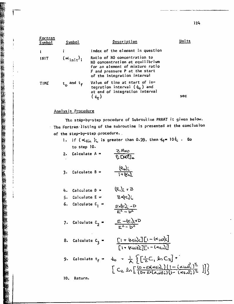
124
FortranSymbol Symbol Description Units
Ii Index of the element in questionINIT (4 )initi Ratio of NO concentration to
: t NO concentration at equilibrium
for an element of mixture ratioF and pressure P at the startof the integration interval
TIME to and tf Value of time at start of in-tegration interval (-) andat end of integration interval(•) sec
Analysis Procedure
The step-by-step procedure of Subroutine PRRAT is given below.
The Fortran-listing of the subroutine is presented at the conclusion
ii of the step-by-step -procedure.
1. If (oCL"n );_ is greater than 0.99, then-kF 10i, . Go
to step 10.
2. Calculate A =
3. Calculate 8 =
4. Calculate D = , r-
5. Calculate E =
6. Calculate C1 =
7- Calculate C2 - _ --______
8. Calculate C3 = 3ILi- t &-j.
9. Calculate t= -rI
10. Return.

125SUBROUTINE PRRAT(INITtFIN!SiTIME9I) PRRO0000REAL INIT PPRR'010COMMON/DATAI/AIR (SO) R(50) X(50) ,FF (50) ,BCON1 150) ,RCONý)(5O) ,'H2 (PRROO)O20
1S0).ZP(70),CUMDIS(70),VPRHOC501,BCON6(scflAfT(5o),PPiFp~NOXPsRl~buP~R*ro302) ,R6(50) 'EKI (50) tEK?(50) ,A2tA3,XLCN,8ETASPHIPEKSXEN~rtjd PRR*0040COI*ION/OUT4/CONGNO(SO) ,OEL'40(So) AREADsASLOPEDMFU0,SLOPE(50) ,TSLOPRR*005o1PENOP(50),EKKt~,DHFTUOM(50),ODDM(50), FBi50),0I4FU0,AIiROOMFFEDPRR*00602,IRSiJB~SIG.SIGZERAVEMIIOMDDAtS0) ,0M0D(014S) ,Dt.VP(50),DI4DPP(50) vFPRR~o0703PRImE(50) ,NOEQXrANOAQQOIFNO(50) vNOZERO(50) wROOT 50 ,SUEA(50) PRR*00ao
C****PRR*0090C**** CALCULATE CONSTANTS PHR*Pl~o
!W C**** PR* 0o110IF(FINIS*GT&0.99) GO TO0 2000 PRR*0120A =(2.0o30.cbuCRHO(U)*CONGNOtI)) PRP,01309 Rbtl,/(l.+Ek2ti)) PR04E 6EK1I PRR*0160R .DUMMY (E*EKIl)-D)/(E'E-D*D PRR*0 170
DI.JI*YA (E-EKl(I)*D)/(E*E-D*D) PRR*ol8o
C****PRROO 190IICo*** CALCULATE TIME PRR@02ooC****PRR* 0o21
TIME =(1./A)*( (0.5.DUMMY.ALOG(oUMMYB)) .(DUt4MYA*ALOG( ((D4E*FINIS)*PRR*0230ISQRTt1.-INIT*INITV)/((,E*INIT)*SQRT(1. -FINISOF14.gIS))))),TIME PRR@024oII 0 TO 1000 PRR*0250
2000 TIME =10*0*TImE PRR*0260w1000 RETURN PRR*0270
END PRR*0280

126
APPENDIX IX - SUBROUTINE MINT
The function of Subroutine MINT is to provide an interpolated
value of a tabulated function of one variable assumipg a linear,
logarithmic, or exponential relationship.
Subroutine MINT is called by Subroutines PRCALC, ZlNTER, DILUTE,
CALCBC, and ZMASS; it does not call any other subroutinas. Subroutine
MINT does not require external input and does not provide external output.
internal input and output are transmitted as argumentl of the subroutine.
The internal input consists of:
ILN NTAB X XTAB YTAB.
The internal output consists of:
Y
Fortran Nomenclature
The following table gives the Fortran nomenclature for those
symbols used in Subroutine MINT. Since the subroutine may be used with
any consistent set of units, the units of the symbols are not specified.
FortranSjmol Sybol Description Units
A a Ccefficient in the expression forY as a function of X
B b Coefficient in the expression forY as a function of X
ILN Indicator:ILN=I if 'inear interpola-tion is requiredILN=2 if logarithmic inter-polation is requiredILN=3 if exponential interrpolation is required
N n Index of the tabular-entry
NTAB N Number of tabular ertries
NI n I Index of the tabular entryprecedirg X
N2 n2 Index of the tzbular entryfol lowing X

• -127
-FortranSymbol Symbol Description Units
* X Value of the independent variableat which interpolation is required
-m.AXTAS(N) Xn Tabular entries of the independent
- variable
Xl Xn1 Value of the :inder-endent variable, at n,
X2 Xn2 Value of the independent variableat n2
Y Y The va-lue of 'the dependent variableto be inte~rpolated
YTAB(N) Tabular entries of the dependentvariable
YI Yn, Value of the dependent variableI at P,
Y2 Yn2 Value of the dependent variableI_ _ at n2
Analysis Procedure
The step-by-step procedure of subroutine MINT is given below.
The F&tran listing of the subroutine is presented at the conclusion
of the step-by-step procedure.
1. If there is only onie tabular entry, set Y.Y, and return.
2. lf'linear or logarithii.c interpolation is specified, exclude
extrapolation; that is,set Y-Y ' if X- x!
set Y-Yn if X 7)(a"nd return.
"3. Determine the tabular entries n1 and n? between which Xl-es..
4. Exclude those cases for which the interpolation formulas
will degenerate, that isset set = _L i
• . , ~or, set - Y•'- •'ni if '•,:"f n .
5. If linear interpolation is specified, set
; aI-~

128
where c•.•-Yn -- ,A"h
anti
and return
6. If logarithmic interpolation is specified, set0'.* b/X
where
2j:ii /nand Xnl.?IaJy 'l)
__ and return.7. If exponential interpolation is specified; set
•j y= Y/'b
WKI where
andb
ii and return.
El
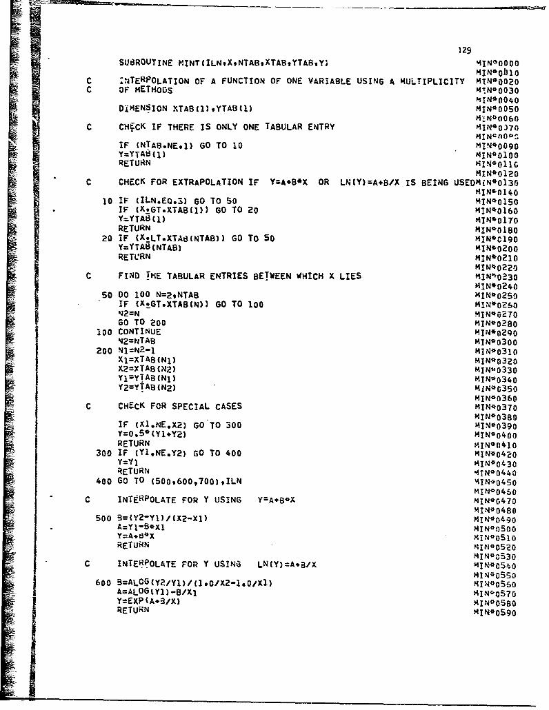
129SUt3ROUTINE ViINT(ILNgXtNTABXTAB#YTAB#Y; t4IN*O0O0
I4IN*01310C :;JTERPOLATION OF A FUNCTION OF ONE VARIABLE USING A MULLTIPLICITY MIN*0020C OF mE.'H0DS H'NO0030
MI N*0040DIMENSION XTAB cI) YTAB(l) MIN-OOSO
MIN*0060C CHECK IF THERE IS ONLY ONE TABULAR ENTRY MIN00370
MIN4A00f:-,IF CNTA8.NE.1) 60 TO 10 MIN~O090Y=YTA8ý(I) '4iN*0 100
L i 2 ~;;9W~d1;O T 20MIN*O120
C CHECK FOR EXTRAPOLATION IF Y=A*B*X OR LNCY)=A.B/X IS BEING USEDMiN*013010 IF (ILN.EQ.3) GO TO 5O MIN*0150
I xG*TB )) GO TO 20 MIN*016OY=YTA (NTA) MI N* 020:1RETU.RN MIN*0180
C 0 lFI (X-THETABULR NTRIES BE To EE 50C XL MIN*0130
50 0 10 N2NTAB) MIN*02S0
RETCN MIN*0210
100 COTINUEMIN*o22oIj FI2NDTHETBLRETREABWEWIHXLE MINqO2300200 NN2-1MIN*031o
soDo100TAN=29) MIN*0250I X2 G~XT ABB) GO42 TO10 N*0330j 142= AN 1 MIN*62TOGOYTO (200 MLN*0280
C o CHOCN FRTPEIAUCSE MIN*0370
RE=TURN MIN*0300200 N=N2-1M1N* 0010
300 IF Y1NE.Y) GTO00MIN*0320
Yl=YTA(1 MIN~0o34
MIN*0360C INTECKFRPOLA ECOAL CASENS A.O MIN~o370
MIN*0480I00 B(X2Y1/X2-x)GOT30 MI-N*0390Y=Ai.5*YX Y MIN*0400RETURN 1 I N*0320
MIN*043OC INTtRPOLATE FOR Y USING NY):A.B/X MINOG4705
MIN1*0480600 3=A0(Y2/Yl)/ 1.0,X2i) 0~ 1411*0490
A=YALOG I M1 B/1141*0570
RETURN1 MIN*0520II*03C NEOAEFRYUIG1NY=*/ i%~~~

1301 I N* 0600
c INTERPOLATE FOR Y USING YZA/X*98 MIN*0610
700 B=ALOG(yl/y2)/ALOG(X2/Xl) MP0N0630A=Y1@Al**B 141N*0640YZA/X**f3 11N00650RETURN 11N*0660
END MIN*0670

131
APPENDIX X - SUBROUTINE CALCBC
The function of Subroutine CALCBC is to zalculate the value of
the mass flao coefficient at each axial station in the combustor primary
"-and intermediate zones.
Subrdutine CALCBC is called by Subroutine ZHASS; it,. in turn,
calls Subroutine MINT. Subroutine CALCBC does not require external
input and does not provide external output. Internal input and output
are transmitted as arguments of the subroutine and through COMMON. The
internal input consists of:
CUMDIS MSTARD ZP ZPD
The internal output consists of:
C
Additional Fortran Nomenclature
The following table grves the Fortran nomenclature for those
symbols in Subroutine CALCBC which are not included in COMMON.
Fortran
Symbol Symbol Description Units
C CXD Mass flow coefficient gm/sec
P1 Value of the cumulative normaldistribution at Zp
P2 Value of the cumulative normaldistribution at -Zp
ZPD Limit of integration of ihe cumulativenormal distribution
Analysis Procedure
The step-by-step procedure of Subroutine CALZBC is given-below.
The Fortran listing of the subroutine is presented at the conclusion of the
step-by-step procedure.
1. Using Subroutine MINT, calculate P1
2. Calculat*.. P2 as
jLi-'

132
3. Calculate CXD as:
c~o : •np / (,- ?•.)
4. Return:
Ii
I
t±

SUBROUTINE CALCBC(ZPDvC) 33CAL*0000REAL MSTARDMSTARU CALOO010COPMiON/tDATAI/AIR(50O,RR(5O),XX(S0) FF(50),BCONI (5O),BCON2(5O),C112(CAL*0020150) ,ZP(70) ,CU14OIS(7O) ,VPRHO(50) ,BCON6(50) ,ATT(50) ,PPPFNOXPR1 (50CAL*00302) ,R6(bO) ,EKl (So) EKZ(50) A2,A3.XLCN,8ETASPHIPEKSXEUlDA1 CAL~bo4oCOI4MON/OUT5IMSTARD ,MSTARU CAL*0050
M7CALL MINT(19ZPD#709ZPtCUNDIS#Pll CAL*0060P2 = l.0-Pl CAL00071C =MSTARO/(Pl-P2) CAL*0080RETURN CAL00090END CAL*o100
VIRR
P-
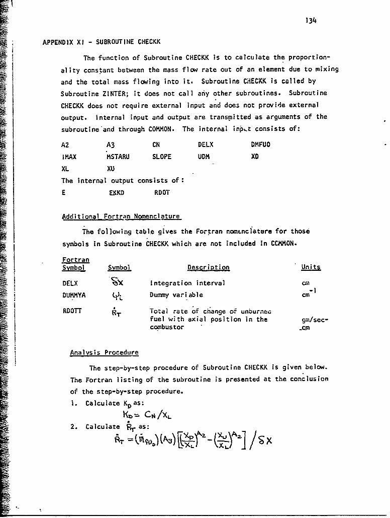
134
APPENDIX XI - SUBROUTINE CHECKK
I The function of Subroutine CHECKK is to calculate the proportion-
ality constant between the mass flow rate out of an element due to mixing
and the total mass flowing into it. Subroutine CHECKK is called by
S1Subroutine ZINTER; it does not call afiy other subroutines. Subroutine
I CIHECKK does not require external input and does not provide external
output. Internal input and output are transmitted as arguments of the
subroutine'and through COMMON. The internal inpLt consists of:
A2 A3 CN DELX DMFUO
IMAX MSTARU SLOPE UDM XD
XL XU
The internal output consists of:
E EKKD RDOT
Additional Fortran Nomenclature
The following tabl.e gives the Fortran nom~Lnclatare for those
symbols in Subroutine CHECKK which are not included in CCKMON.
FortranSym bol Smbol Descrinpti2on Un
DELX Integration interval crn-1
DUMMYA Dummy variable cm
RDOTUT Total rate of change of unburneGfuel with axial position in the gm/sec-
combustor _0.
Analysis Procedure
The step-by-step procedure of Subroutine CHECKK is given below.
The Fortran listing of the subroutine is presented at the conclusion
of the step-by-step procedure.
1. Calculate K as:
1 C /xL
2. Calculate as:
A-I

135
3- For the element in question, calculate E and R•,as:
Step 4 is performed only if C>
4. Go to step 7.
5. Calculate LL as:
Step 6 is performed only if U; 7/ 1
6. Calculate Ei as:
.Ej = iL Ia,
7. If this is the ].ast element to be considered go to step 8.
If not, return to step 3.
8. Return-
I

136
S0t3ROUTINE CHECKKcnELX) C:HK*0010IREAL MSTARU CHK*0010I ~~DIMENSION DUMMYA(50) C40~
f.j OMMON/OATA1/AIR(50) ,RRt5O) XX(S0) ,FF(50) ,BCON1 (50) ,8CON2(50) C2(H*03
1 50) .Z'(7O) ,CUMDIS(70) ,VPRMO(50) ,BCON6(50) ,ATT(50) ,PPPFNOXPR1(50CHK*0040
CO.MMON/OUT3/INOICNO(50) ,AVETTAUBARRH08AR,'2HI8ARIMAXXD* CHK*0060
I1FBARDXUtLENTAUINT,TAUDILVELOC CK07
I ~~COMMON/OUT4/CONGNO(50) ,DELI4D(5fl) AREAOASLOPEDMFUiOSLOPE(S0) ,TSLOCHK*0080
LK IPENOP(50),EKKDOMFT9UDM(50)tDDt4CS0)9 F8(5O),DMFUDAIROOMFFEDCHKOO090I ~2,RSUBXSIGSIGZERAVEMWDMDDA(50) ,DMDDM(50) ,MOMDP(50) ,QMDDPP(50).!iCHK*0100
3PRIME(50),NOEGXDANOAQQOIFNO(50)9NOZERO(50)9ROOT(50)9E(SO) CHK*O110
"COMt4ON/OUT5/MSTARDtMSTARU CH.K*0120
CO**@ CALCULATE K CHK*0140
C**** CHK*015O
EKKD=CN/XL CHK*01?0
C**** CtiCK K VALUE CHK*0O180
Wz C****CHK*0 190
RDOTT = DMFUO*A3*( ((XO/XL)**A2)-( (XU/XL)**A2) )/DELX CHK*0000
DO 1000 I=191MAX CHK*0016
E(I)=EKKO CHK*0220
RDOT(I) =RDOTT*UDM(I)/MSTARU CHK*0230
IF(UDM(I).EQ*0.O) GO TO 1000 CHK*0240
OUMMYA(I) a-(SLOPE(I)'"RDOT(I))/UOMC!) CpiK*050
IF(OUMHYACI)eGE*EKKO) E(I)a1.100UMMYA(I) CHK~o26o
1000 CONTINIIE CHK*0270RETUr~f CHK*028OEND CHK*0290
ro
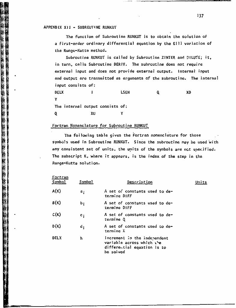
137
APPENDIX XI1 - SUBROUTINE RUNKUT
The function of Subroutine RUNKUT is to obtain the solution of
a first-order ordinary differential equation by the Gill variation of
the Runge-Kutta method.
Subroutine RUNKUT is called by Subroutine ZINTER and DILUTE; it,
in turn, calls Subroutine DERIV. The subroutine does not require
external input and does not provide external output. Internal input
i l and output are transmitted as arguments of the subroutine. The internal
input consists of:
DELX I LSGN Q XD
IYThe internal output consists of:Q xu Y
Fortran No.,menclature for Subroutine RUNKUT
The following table gives the Fortran nomenclature for those
symbois used in Subroutine RUNKUT. Since the subroutine may be used with
any consistent set of units, the units of the symbols are nca specified.
The subscript K, where it appears, is the index of the step in the
Runge-Kutta solution.
FortranSymbol Symbol Description Units
A(K) ai A set of constants used to de-termine DIFF
B(K) bi A set of constants used to de-termine D1FF
C(K) ci A set of constants used to de-
termine Q
D(K) di A set of constants used to de-temine X
DELX h Increment ;n the indenendentvariable across which L½ediffere,.tial equation is tobe solved

138
S~FortranSymbol Symbol Description Units
DELY k. Product of YPRIME and DELX ateach stage of the solution'
DIFF A•Y The change in the value ofthe dependent variable ateach stage of the solution
I Index of element
K Index cf the stage of thesolution
LSGN Indicator:LSGN=I if intermediate zoneand not the lest step in thezoneLSGN=2 if interi 3te zoneand the last ste- in the zoneLSGN=3 if dilution zone ordilution zone type calculation
SQ qQuantity used to calculate DIFFat each stage of the solution;the value of Q in the final stagecf the solution is a measure of theround-off error in Y
X I X. Value of the independent variableat each stage of the solution
Y Y. Value of the dependent variableat each stage of the solution
tix_ YPRIME f(XiX) Value of aY/87 at each stageof the solution
Analysis Procedure
The step-by-step procedure of Sibroutine RUNKUT is given below.I The Fortran listing of the subroutine is presented at the conclusion
of the step-by-step procedure.
1. Calculate the value of the independent variable at the
given stage L 'if the solution as
2. Using Subroutine DERIV, calculate the value of-ý(XLj
at the given stage of the zolution.

139
3- Calculate kL at the given -ýtage of the solution as:
4. Calculate the change in the dependent variable at the
given stage of the solution as:
5. Calculate the value of the dependent variable at the given
stage of the solution as:
Step 6 is performed only if Yz'O. Ify.•O go to step 7.
6. Set YL-o.
7- Calculate c6L as:
8. If this is the last stage of the solution, go to step 9.
If not, return to step 1.
9. Return
H

SUBROUTINE RUNKUT(X#DEL.XtYtQtLSGN)I) RUN00000
IDIMENSION A(4)tB(419Ct4-)iO(4) RUN4OOIO
DATA (A(I),Il,94)/O.BsOe2928932,1.707lO689OI1666667/9(B(I)9I1=14) RUN*002O
1/2.o,1.o,1.O,2.0/,(CCI),Ilzl94)/0.5.0.292B9329l.7O7lO689Oo5/9 RLJN*0030.
2(DCI)#I1,94)IO.O.0.So.OqO*SI RUt4.0050
C** RUNKY! SOLUTION OF A FIRST ORDER ORDINARY DIFFERENTIAL EQUATION RIJN*0060
BY THE GILL. VARIATION OF THE RUNGE-KUTTA METHOD UO7c****RUN*O0080.
I00 100 K=194 RON*0O9O.
IX = *D(K)'OELX RLJN*0100
CALL DERIV(XYYPRIMELSGNtI) RUN*0110
DELY =YPRIME*DELX RUN*0120
DIFF =A(K)*C0ELY-RCK)*Q) RUN*0130
Y =Y+DIFF RUN*0140
IF(YjLT.O.O) Y=0.0 RUN*015O
100 0 Q+3.O.DIFF-C(K)ODELY RUN*0160
RETURN AUN*0170
END RUN*0180

141
APPENOIX XIII - SUBROUUINE DERIV
SThe function of Subroutine DERIV is 5 to calculate the rote of
formation of nitric oxide with resperct to axial distance in the combustor
intermediate or dilution zone.
Subroutine.DERIV is called by Subroutine.RUNKUT; it does not
call any bther subroutines. Subroutine DERIV does not require external
input and does not provide external output.; Internal input and output
are transmitted as arguments of the subroutine and through COMMON. The
intern3l input: consists of:
AREAD ASLOPE CONGNO DDM
DDDP E, EKI EK2FNOXP I LSGN 14STARDIiNO NOEQXD NOP NOZERO
RDOT RI R6 SLOPE
UDM XD Y
The internal output cons:sts of:
DILL REAT YPRIME
Additional Fortran Nomenclature
The following table.gives the Fortran nomanclature for those
symbols in Subroutine DERIV which are not included in COMMON.
Fortran
S-Ymbol Symbol Descriotion Units
DFLAME Rate of change of elemental NOconcentration with axial positionin the combustor intermediate zone -ldue to formation of "prompt NO" cm
DMIXT VTOT Total rate of change of elemental
NO concentrati6n with axial position
*in the combustor intermediate zonedue to mixing cm

142
FortranSmo Symbol Description Units
• ~DRIX]•,•'I Rate of change of elementalNO concentration with axial
position in the combustorintermediate zone 4ue tomixing into the element cm
DMIX2 Rate of change of elementalNO concentration with axialposition in the combustor in-termediate zone due to masschange mixing term cm
DMIX3 Rate of change of elemental NOD3 concentration with axialposition in the combustorintermediate zone due tomixing out of the element cm
FNOXG NO formed in the flame
front (mass fraction)
i Index of element
LSGN Indicator:LSGN=1 if intermediatezone and not the laststep in the zoneLSGN=2 if inteimediate
zone and the last stepin the zoneLSGN=3 if dilution zoneor dilution zone typecalculation
RAT Ratio of NO concentration to NOUM concentraticn at equilibrium for
an element of mixture ratio Fand pressure P at axial position
Y0 ; ratio of NO concentration toNO concentration at equilibrium ataxial positionX!
X Axial position (downstream) in thecombustor cm
Y y xO D Nitric oxide concentration foran element of mixture ratio F
190,3XVand pressure P (mass fraction)at'XD; nitric oxide concentration
at XD
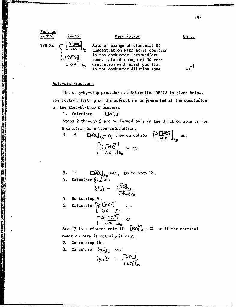
143
FortranSymbol Smbol Description Units
YPRIME - ENIL Rate of change of elemental NOL x•" concentration with axial position
L ~ in the combustor intermediate
zone; rate of change of NO con-L entration with axial position
W in the combustor dilution zone cm
Analysis Procedure
The step-by-step procedure of Subroutine DERIV is given below.
The Fortran list-ing of the subroutine is presented at the conclusion
of the step-by-step procedure.
!. Calculate 00001
Steps 2 through 5 are performed only in the dilution zone or for
a diluti.on zone type calculation.
2. If ["Oj,ýýo, then calculate 1 as:L x JXD
3. If L•=•D -- ) go to step 18.I 4. Calculate D~)a's:
5. Go to step 9.
6. Calculate rSO] as:
L -A.
Step 7 is performed only if Lt401=o or if the chemical
.reaction rate is not significant.
7. Go to step 18.
8. Calculate Z(ZLb as:
E 0.j

144
9. Calculate ON)
Steps 10 through 13 are performed in the intermediate zone
except. for the last step in the zone.
10. Calculate , , and
11. Calculate (M,( Y xITcr as:
~ 112. Calculate as:
13. Go to step I
Steps 14 and 15 are performed only for the last step in the
Intermediate zone.
14. Calculate •t i as:
15. Go to step 18
Steps 16 and 17 are performed in the dilution zone or for a -ilution
zone type calculation.16. Calculate
17. CRlculate turnoI1 •as:E- j
18. Return

SUa3ROUTINE DERIVCXvYYPRIMEtLSGNI) 15DER*0000REAL '4STARDMSTARUsNOP ,N0EQXONO DER*0 010ICOI4MON/DATA1,ATR(50) ,RR(50) 'XX(50) .FFC50) ,BCON1 (5ý ,iBCON2(50 ,CH2(OER0002O150) ,ZP(70) ,CUMOISC7O) ,VPRtO(5O) ,BCON6(50) ,ATT(50) ,FqPFN0XPR1 (SOOER@003()2),R6(5o),EK1(50VEK2(50),A2,A3,XLCN,8ETASPHIPEKSoXENDAl DER00040COJ*ION/OUT3,EINDICNOfSO) ,AVETtTAUBARRHOEbARtPHI8ARL4AXXD, DER*0050JF8ARD9XULENTALINTTAUDI~,VELOC DER*0060COMMON/OUT4/CONGNO (50) DELhtD(50 ,AREADASLOPEDMP4U0,SLOPE (50) ,TSLODEk*0070U 1IPENOP(50) ,EKKoD0MFTUDt4(50) .001(50), FB(50) 0ML'jDAIR0DJ4MFFEDDER@00B02,RSUBASIGSIGZERAVE?4h1D,400A(50) ,0330M(50) ,DMODP(50) ,O140PP(50) ,FDER*00903PRIME(50),NOEQXDANOAQQDIiNO(50),NOZERO(50),RDOT(50),E(50) DER90 100CO4MM0t, UT5/1MSTARD,MSTARU DER*0 110I.COMMON/OUT6/REAT, DILL DER*0120FNOXG =FNOXP.1.0E-06'(3090/28,O) DER*0130IF(LSGN.NE.3) GO TO 500 OER*01 40IF(NOEOXD.EQ.C,.0) YPRIME a 0.0 DER*0150IF(NOEOxD.EQ.0.0) GO TO 4000 OER~ol6GRAT a Y/NOEQXD DER*0170GO TO 750 OER~nlS0
500 CONTINUE OER*0190YPRIMEzo.0 DER*0 200IF(CONGNO(I).EO.O.O.OR.NOZERO(I).EO.1) GO TO 4000 DER*0 210RAT = Y/CONGNOMI DER*0220
750 CONTINUE DER*0 230YPRIME=,((2.O*3O.0)/(M4STARD/AREAD))e(1.0uRAYTkAT).4(RlcI)/(1.0.(RA0EReO24oIT*EK1(I )) ).(R6(I)/(190*EK2CT))))) OER*0250REAT 2 YPRIME DER*0260GO TO (10009200093000),LSGN DER0o270
1000 DMIX1=(DI4ODP(I)+RDOT(I))*NOP(I) DER*0280D14IXzE(I)*UDM(I)ONO(I) DER*0290Dl4IX3rSLOPE(I) *NO(I) DER*0300DFLAI4E a FNOXG*RDOT(I) 0ER*0310
DMIxT = DMIX1-0141X2-DMIX3#DFLAI4E OER*0o32
YPRIME =DI4IXT*REAT DER~o340
GOTI00DR05

146
APPENDIX XIV - SUBROUTINE ZMASS
The function of Subroutine- ZMASS is to determine the mass flow
in each element of the distribution function at a prescribed axiai
station in a gas turbine combustor. in addition, ZMASS calculates
the mean mixture ratio, total mass flow, ahd the airflow rate at
each of these axial stations.
Subroutine ZMASS is called by Subroutines PRIMRY, ZINTER, and
DILUTE; it, in turn, calls Subroutines CALCBC and MINT. The subroutine
does not require external input but does provide external output.
Internal input and output are transmitted as arguments of the sub-
routine and through COMMON. The internal input consists of:
AIR Al A2 A3 BETA
CUMlIS DDM DELX EKS FF
INDIC MSTARD PHIP PPP RR
S VP XD XL XU
XX ZPThe internal output consists of:
!AIRD AREAD ASLOPE DDM DELMD
DMFFED DMFT DMFUD DMFUO FB
FBARD IMAX MSTARD MSTARU NOZERO
SIG SIGZER SLOPE TSLOPE UDM
The external output consists of:
AFR DDM FEDF FULOAD IHIGHD
I LOWD
Additional Fortran Nomenclature
The following table gives the Fortran nomenclature for those
symbols used in Subroutine ZMASS which are not included in COMMON.
FortranSymbol Symbol Description Units
A A Lower integration limit for the evaluationof the cumulative normal distributionintegral

147
FortranSymbol symbol Description Units
ADDH Gm)A Dummy variable gm/sec
AFR A/F Over-all ai:-to-fuel ratio
AIRI (AA)l Airflow rate at the primary zone exit gm/sec
AIRU (MAAXU Airflow rate at the upstream axialUi.-egration limit of the combustor gm/sec
SB Upper integration limit for the evaluationof the cum~ulative normal distributionintegral
C CXD Mass flow coefficient gmsec
DELX ZX Increment of the combustor length acrosswhich the solution is generated cm
DUNIY (FB)DUM Dunmmy variable
FEDF (Af)f Total mass of fuel fed into the combustor lb/hr;lb/sec
FJLOAD Y Fuel loading lb/sec-ft 3-atm2
1 i Index of the element
I H, GHD (OIGP)D Subscript of the mass element with the
highest equivalence ratio (downstream end ofintegration interval)
IHIGHU OHIGH Subscript of the mass element with the highestequivalence ratio (upstream end of integrationIt interval)
ILOWD (ILOW)D Subscript of the mass element with the lowestequivalence ratio (downstream end of integrationS~interval)
ILOWU (0ILOW) Subscript of the mass element with the lowestequivalence ratio (downstream end of intcgrationinterval)
IN Counter; indicates first mass element with zeromass at upper end of equivalence ratio distribu-tion function
MOUNT KKKOUNT Indicator
KKOUNT = 0 if FB(I)i-.2F for the element iKKOUNT - 1 if FB(I)72T for the element i
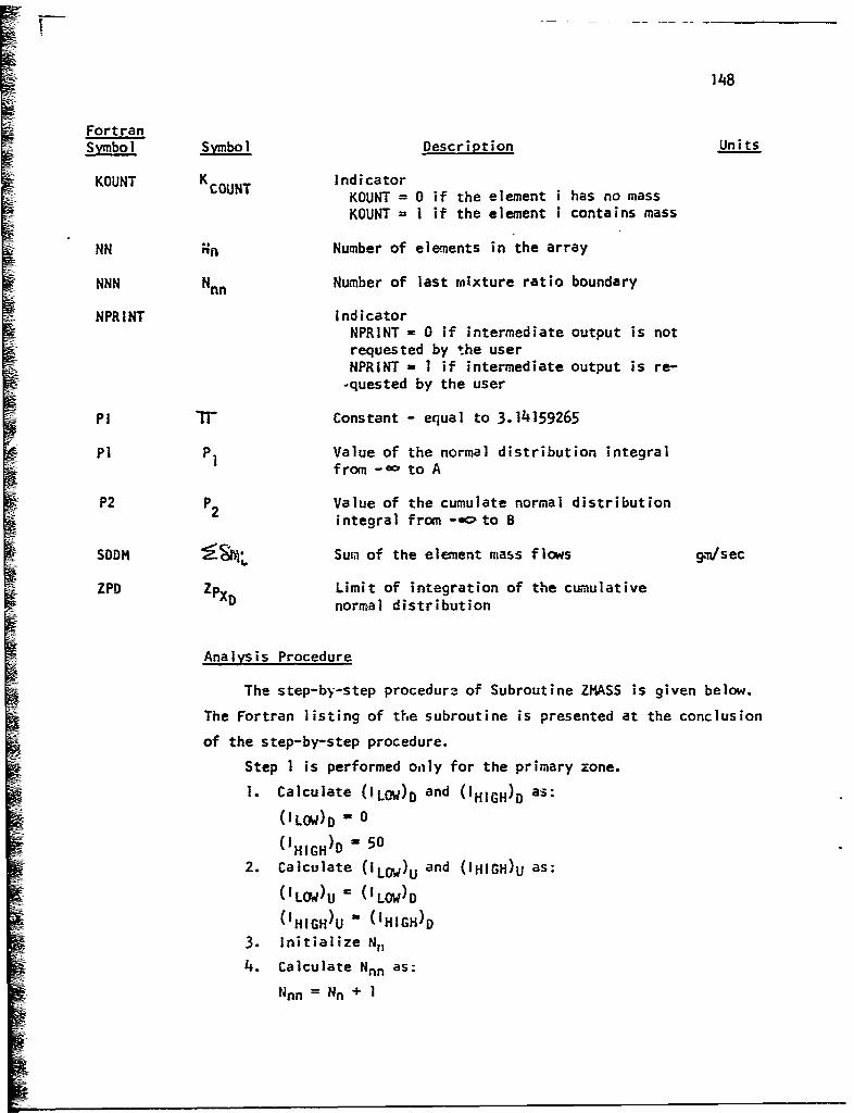
148
FortranSymbol Description Units
KOUNT K COUNT indicatorKOUNT = 0 if the element i has no massKOUNT = I if the element i contains mass
NN Rn Number of elements in the array
NNN Nnn Number of last mixture ratio boundary
NPRINT IndicatorNPRINT - 0 if intermediate output is notrequested by the userNPRINT - I if intermediate output is re-
-quested by the user
Pi IT- Constant - equal to 3.14159265
PI PI Value of the normal distribution integral1 from -a- to A
P2 P2 Value of the cumulate normal distributionintegral from -=oto B
SDDM •M Sum of the element mass flows gm/sec
ZPD Limit of integration of the cumulative0ZPD normal distribution
Analysis Procedure
The step-by-step procedur3 of Subroutine ZMASS is given below.
The Fortran listing of the subroutine is presented at the conclusion
of the step-by-step procedure.
Step I is performed only for the primary zone.
1. Calculate (ILOW)D and (OHIGH)D as:
(ILOW)D - 0
(IHIGH)D 50
2. Calculate (ILow)U and (IHIGH)U as:
(ILOW)U (LOw)D(IHIGH)U - (IHIGH)D
3. Initialize N,14. Calculate Nnn as:
Nnn = Nn + 1

149
5. Initialize -_.j "as:
6. Using Subroutine MINT, calculate (J•A~
7. Using Subroutine MINT, calculate A•r
7. Using Subroutine MINT, calculate
9. Using Subroutine MINT, calculate
10. Calculate A XD as:
A r
11. Calculate as:
Step 12 is only performed in the intermediate and dilution zones.
12. Calculate the fuel'Ioading, 4) as:
Step 13 is performed only in the intermediate zone and if JL 0.13. Write the fuel loading, to
14. Calculate (Ifdo and (Mf f as
15. Calculate the over-all air-to-fuel ratio A/F as:
A/FIV=A
16. Readjust the units on (Mf)f from lb/sec to lb/hr.
Step 17 is only performed for the primary zone.
17. Write (Af)f and A/F.
Step 18 is performed only in the dilution zone.
18. Calculate (¶s•o~as:
Step 19 is performed only in the primary and intermediate zones.
19. as:
(&~ [i A3
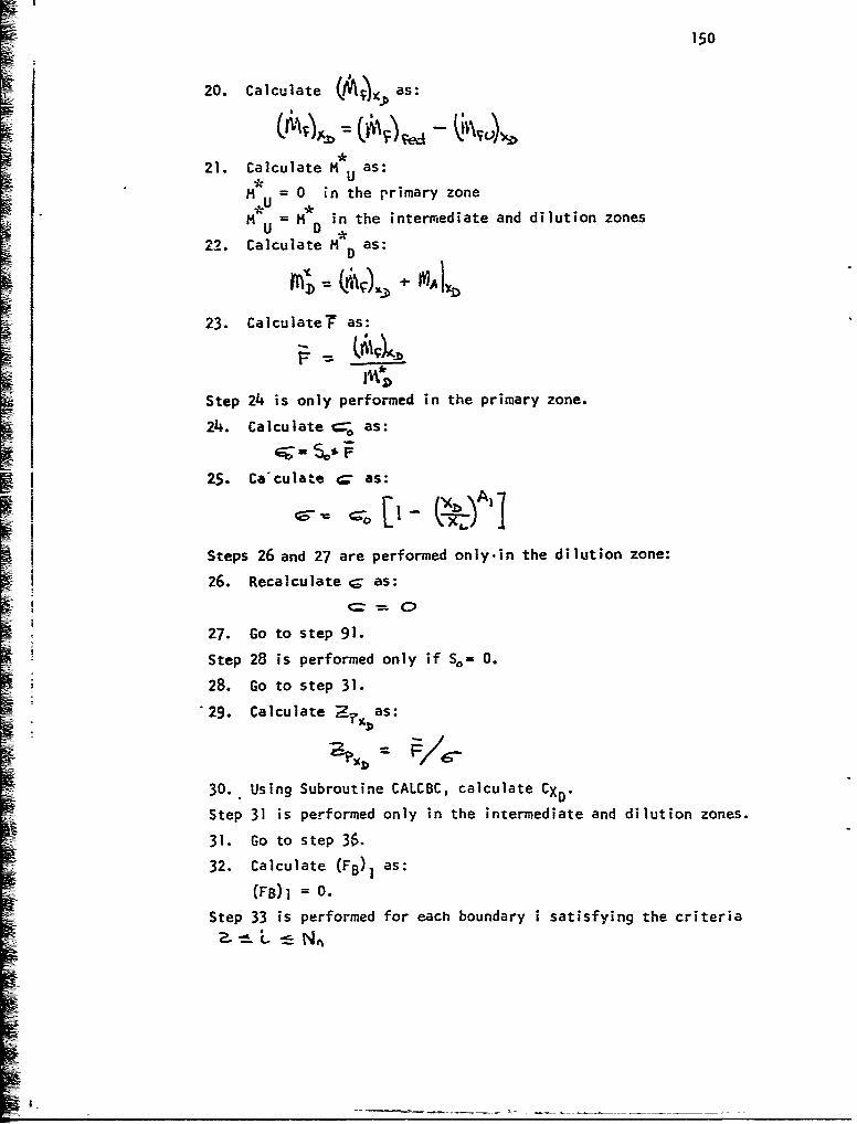
150
20. Calculate M as:
*3
21. Calculate H as:U
%•U = 0 in the primary zone
U = M in the intermediate and dilution zones22. Calculate H D as:
I
23. CalculateF as:
Step 24 is only performed in the primary zone.
24. Calculate = as:
S125. Ca-culate 4c= as:
Steps 26 and 27 are performed only.in the dilution zone:
26. Recalculate 4 as:
27. Go to step 91.
Step 28 is performed only if So= 0.
28. Go to step 31.
*29. Calculate F D as:
30. Using Subroutine CALCBC, calculate CXD.
Step 31 is performed only in the intermediate and dilution zones.
31. Go to step 36.
32. Calculate (FB)l as:
(FB)1 = 0.Step 33 is performed for each boundary i satisfying the criteria
L,

ii 151
S33. Calculate (F8 )i as:
34. Calculate (FB)N as;
35. Go to step 41.
Steps 36-and 37 are perfoimed for each element i satisfying the criteria
36. Calculate 1ý14 as:
(S mi) = 0in the primary zone
S•M"U in the intermediate and dilution zones
37. Calculate as:
I b = o
Step 38 is performed only if N38. Go to step 411.
-Steps 39 and 40 are performed for each element i in the array
satisfying the criteria (L + -I) i i • N.
39. Calculate as:
40. Calculate (,• as:
41. Calculate LL.X as:
thX = 50
Step 42 is performed only for the special case that So= 0 in the
primary zone.
42. Go to step 44.
43. Go to step 49.
Steps LA through 48 are perforvied for each element i in the array
satisfying the criteria 1.-- ; t ý w "
44. Calculate and ( ]L for tie next element as:
Step 45 is performed only if (FB). .

N 152
45. Go to step /44.
46. Recalculate & rs:
47. Calculate and as:
48. Go to step 92.
S49. Initialize the Indicators KCOUNT and K.KOUNT-as
K COUNT 0
K =0KOUNTSteps 50-85 are performed for each element i in the array
satisfying the .criteria - "'-.Ilnii
Steps 50 and 51 are performed only if the element i Is
equal to Nnn.
50. Calculate Lox as:S•-/•h;( = nn- l
51. Go to step 75.
Step 52 is performed only if (r-b) L -s Z=
52. So to step 54.
53. Calculate b)oo^ (Fs)ý , •,, :.and k,,• as:
• a?
(fflAx M. -
54. Calculate the distribution integration limits as:
Steps 55- and 56 are performed only if A 710.
"55. Using Subroutine MINT, calculate P,, the value of the normal
distribution integral from-, to A.

153
56. Go to step 60.
57. Calculate A as:
A - -A
58. Using Subroutine MINT, calculate the value of the normal
distribution integral from - o to A
59. Recalculate PI as
P = I-PI
Steps 60 and 61 are performed only If 8 7/0.
6P. Using Subroutine MINT, calculate P2 9 the value of the normal
distribution integral from - oO to B.
61. Go to step 65.
62. Calculate B as:B=-I-B
63. Using Subroutine MINT, calculate P2 3 the value of the normal
distribution integral from -oo to B.
64. Recalculate P2 as:
P2 I"P-2
65. Calculate (5m)D as:
Step 66 is performed only if (%ML•7 0.
66. Set (ILow)D equal to 1.
Step 67 is performed only if (ILOW) D 0.
67. Go to step 69.
Step 68 is performed only if ~11,=0 and
68. Set (ILGW ' equal to i-.
Step 69 is performed only if .$m&-) 7 o.6!1. Reset KCOUNT as:
KCOUNT I
Step 70 is performed only if - 0 and if
KCOUNT ].
70. Go to step 77.
Step 71 is performed only if (i-i) L • .
71. Go to step 74.
YR

S1 54.
72. Caieulate •ar':L as:
73. So to step 8 3.
74. Calculate ('5tv4 as:
ealCUlate SfI-Nad s
76. Go to step 81.
77. Calculate (ý;vv,-2)~ ~L ¾ a-,'I as:
78. Caiuclat6 . and as:
Step 79 is performed e.;', if K 1.KOUNT
79. Calculate (FEXm-sa as:
80. Reset KKOUNT =
Step 81 is performed only if Z T Nnn
81. Go to step 85.
82. Go to step 86.
82 ot se 6

155
83. C•1culate (thML:,1j3 as:
Step 8/+ is performed ohly if tJ"4C 50.
84,. Go to step 86.
85. If' this is the last element in the array, continue to step
86. If not, return to step 50 with i = i + I.Steps 86-87 are performed oily if intermediate output is re-quested by the user.
Step 86 is performed for eech element in the array satisfying4 a
the criteria it- • L
86. Vrite )87. rite LOWD and (I HIGH )*Step 88 is performed if:.Ko- = |'
i KOUNT88. Calculate as:
j Step 89 is performed only in the primary zone.
89. Go to step 92.
Step 90 is performed for each elanent in the array satisfying
-the r.i-teria S k'poý
ii. ,,0. Cacuat ,a. °+ ,,. s:
i - gx90. Calcas:
[~A]
92. Return.
-- - -- - -

SUBROUTINE ZMASSIDELX) ZI4A*0000REAL MSTARDeMSTARU ZMA000IOCOMMON/OATAI/AIR(50) .RR(50) ,XX(50) ,F~F50) ,BCON1 (50) ,BCON2(50) ,CH2(ZMA
0002O150) ,ZP(70) ,CUMDIS(70) VPtflO(50) ,8C0N6 (50) ,ATT (50) ,PPPFNOXPR1 (50ZmA*00302) ,R6(50) ,EK1 (50) ,EK2 (50) ,A2,A3,XLCNBETASPHIPEKSXENDA1 ZMA*0040
COl4MON/OUT3/INDICNO (50) ,AVETTAUBARRHGBAR*PHIBAR,'ktAXXO, ZMA*0050
COMMON/OUT4/CONGNO(SO) ,DEL'4D(50) ,AREA0,ASLOPEDMFUOSLOPE (50) TSL0OZMA*0070IPENOP(SO).EKKDDMFT.UUM(50),ODM(50), FB(50),DpIFUDAIRDDMFFEDLMA*00B0
2,i4SUBASIGSIGZERAVENDt4DODA50,OO(SO) ,OD(0)0DHD~tOP(0) DDPP(50) ,FbiAO0090
3PR114E(50),NOEQXDANOAQQDIFNO(S0),NOZERO(50),RD0T(50),E(50) Z,4A*0100COMMHON/OUT5/MSTARDI4STARU ZA01DATA P113.14159265/ ZMA*0120
ZMA*0130CO*O* CALCULATE AIR FLOW- AND COMBUSTOR AREA Zi4A*0O10
C****ZM~A*0150NPRINT=0 ZP4A*o160IFCINDICeNEe1) GO TO 10 ZMA*0170BILOWD=C ZMA*0180IHIGHD=50 ZMA*0190
10 ILOIU21LOWD ZMA~o2ooIHIGHU*IHIGHD ZMA*0210NN=35 ZMA00220'NNN=NN 1 ZMA*003nSD0mZO*o ZMA*0 240CALL MINTB1,0*0,11,XXAIRqAIRI) ZMA*0250CALL MINT(1,XU*11,XX*AIR#AIRU) ZMA*0260CALL MINT(jXD,11,XXAIRAIRD) ZMA*0 Z70CALL MINT(jXD.11,XXvRRRSUBX) ZMA*o28oAREAD U PI.RSU8X*RSUBX ZMA*0290
ZMAO0300C**** CALCULATE FUEL FLOW RATES AND DISTRIBUTION CHARACTERISTICS Z?4A*O2'0
C****ZMA* 0 320DMFFEO EKS*PHIP*AIRI/8ETA ZMA*0330
~ C'***IF(INDIC.NE.1) FULOAD2DMFFED*12.O**3.042e54**3.0/(4S4.*VP*PPP**2.* ZMA*0340IF(INDIC.EQ.Z.AND.HSTARU.EQ.0.0) bIRITE(698500) FULOAD ZMA*0 3SO
8500 FOIRMAT(/////t1X920bITHE FUEL- LODGI E12*5#28H LB./SEC..CUeFT*.Z4A*0360lATMO.;ATMO.) ZMA*0370
DMFUO aD?4FFED*(1.0-BETA) ZMA*0380FEOF OMFFED/454o ZMA*0390AFR AIR(11)/DMFFED ZMA*0400FEOF FEDF*3600, ZMA*0410IF(INI)IC*EQ.1) WRITE(6,9910) FEDF ZMA00420IF(INOIC.EQs1) WRITE(6,91S0) APR ZMA*0430IF(INDICeEQ*3) DMFUD a 0.0 Z14A*0440IF(INDIC*EQ.3) GO TO 100 Z14A*0450DmFuD x DMFUO*(1.-A3* (XD/XL)**A2) ZA06
100 Ot4FT xDMFFED-DMFUD ZMA*0470IF(INOIC*EO.) 14STARU a 0.0 114A*0'.BIFLINDICeNEa1) MSTARU a MSTARD ZMA*0 '90I4STARO a OMFT*AIt.O ZI4A*0500FEARD a DM4FT/t4STARD biA00510IF(INUIC.EQ.1) SIGZER*S*FBARD ZMA00520SIG*SIGZER* (1 - (XD/XL) **A1) ZMA*0530IF(INDIC9EQ*3) SIG a0.0 ZMA*0540IF(INI)IC.EQ.3) GO TO 8000 Z14A*0550IF(S*EQO..) GD To 500 ZMA*0560
C****ZMA* 0 B7OC**** CALCULATE DISTRIBUTION CHARACTERISTICS AND ZMA*0580
C****ZmA~o59o

:111.157ZPO FBARD/SIG ZmA*0600
-~CALL CALCBC(ZPDvC) ZMA0661 0C****ZMA~b 620
C** CALCULATE BOUNDARIES AT WHICH EACH F VALUE APPLaIES iMA*0630C****ZMA*0b40
500 CONTINUE ZMA*0650
IFCINUICoNEel) GO TO 1500 1MA0066C
F8(1) = 0.0 ZMA*0670
DO 1000 Ix:;NN ZMA*06RO1000 F8(I)8 o*5*(FF(I)*FF(I-1)) Z4A*0690
FBCNNN)=2.0*~FF(NN)-FB(NN) ZMA*0700GO TO 3000 114A*0710
C**** STORE MASS FLOWS AT PREVIOUS STATION ZMA*o730C****ZMA
00740
1500 CONTI1VUE ZMA*o750
DO 2000 I =1,IMAX ZmA~o760
IF(INDIC.*EO:1) UDM(I)= 0.0 ZMA~o770
IF(INDIC*NE 1) UDM(I) a DOM(I) LMA*0780
DELMD(I)zo.0 ZMA0O 190
2000 CONTINUE ZMA*0800
IF(IMAX*EO.NN) GO TO 2200 ZMA*0810
INzIMAX.1 ZMAOB820
DO 2100 IzIN#NN ZMA*0830
DELMD(I)20.0 Z,4A~oS402100 UDM(I) z 0.0 ZM-A*08502200 CONTINUE ZmkA.0860
C**** ZbiA*0870
C**** CALCULATE IMAX ZMA*0 880C****ZMA00890
3000 CONTINUE ZMA00903
I MAX=50 Z,4A*0910
C**** SPECIAL CASE S=090 IN PRIMARY ZONE ZMA*0930
f C**** ZMA0 09 40
IFCS*EQ..O.OANO.INDIC*EQ.1) GO TO 2300 ZMA*0950
GO TO 2500 ZI4A*0960
2300 DO 2400 I=1,IMAX 1MA00970
DD4(i&)=0.0 ZMA*0980
DELMO(Ijz0.0 ZMA*0990
NOZERO(I)=1 ZMA*1000
IF'FBCI).LT*FBARO) GO To 2400 ZMA*0 10
IMAX=I1 ZMA01 020
0DM (I1)=mSTARD ZMA*1 030
DELHI)(I-1 zmSTARD ZMA01040
NOZERO(II1)uo ZMA*1 050
GO-.TO 900~ ZMh0I 060
2400 CONTINUE ZMA*1070
2500 CONTINUE ZMA*1080
KOUNTWo ZMA* 390
KKOUNTzo Z.EA*1100
DO 5000 1 =Z2,NNN Zp4A*1110
IF(IEQ*NNN)'IMAX=NNN-1 Z.MA*1120
IF(I*EO.NNN) Go TO 4880 Z7eA*1130
IF(FB(I)*LT*(2,0OF8ARD)) GO TO 4000 ZIO &140
DUMMY a FB(I) 7MA* 11!50
FB(I) = 2,0*FBAeRO ZIA 0t1 160
"IMAX =I ZI4A-P 17n
KKOUNTX1 ZA4A1 180
4000 CONTINUE Z4119

158C****ZMA*1200
C**** CALCUL-ATE THE ELEMENT MASSES LMA012ioC****ZMA*t220
A = (FB(I)-FBARD)/SIG ZMA*12309 (FBU1-1)-FBARD)/SIG ZMA*1240IFIA.LiEo0.O) CALL MINT(1,A,70,ZPCUMOISP1) LMA912SO
jIF(A*GE*0*O) Go TO 4500 ZMA*1260A a:-A ZMA*1270CALL MINT~lIA,?OZPCUMOISPl) ZMA*1280Pi = :o0P1 ZMA01290
4500 IF!B.~bE0O) CALL MINT(1,8,70,ZPgCUMDISP2) ZMA*1300IF(8.GE*.0O) Go TO 4800 ZMA*1310
CALL MINT(198,7OtZPCUMDIStP2) ZMA*1330SP2 a1.0-P2 ZMA*] 340
4800 ODM(I-1) a C*{P1-P2) ZMA*1350IF(DDm(l).GTo.0) ILOWDsl ZMA*1360IF(ILOWD.GT.o) GO TO 4850 Z'iA*13TOIF(DUMCI-2).EQ,0.0.AND.ODM(I.1).GT.0.0) ILOWDzI.1 ZMA*1380
4850 IF(DDM(11I)*GT*0.0) KOUNTal ZMA*1390IF(DDM(1ml).EQ.O.0,AND.KOUNT.EQ.1) GO TO 4900 ZMAI1400IF((I-1)*EQ*IMAX) GO TO 4875 1MA*1410SDDM=SDDM+DDMCI-1) 1MA*1420GO TO 4950 ZMA*1430
4875 ADDMODDM(I-1) ZMA0I4404880 ODM(I-1)=MSTARD-SDDM ZMA*1450
DELMO(I-1)=DDM(I-1) ZMA*1460IHIGHO=I-l ZMA*1470GO TO 4925 ZMA0148o
4900 DDM(1-2)=MSTARD-SDDM*DDMfI-2) ZMA*1490DELMO(I-2) = DOM(I-2) ZMA*1500DELMD(I-1)uO.0 ZMA91510IHIGHL=IsI2 ZMA*1i520IiAXzI-2 ZMA*1530IF(KKOUNT.EQ.1) FBCIMAX*2)cOUMMY ZMA*1540KKOUNTzo Z,4A*1550
4925 CONTINUE ZA16IF(IMAX.GT*NNN) GO TO 5000 ZA1760 TO 6000 14A*15 80
4950 OELMD(1-1)zODM(I-1) ZMA*159OIF IIMAX*LT*50) GO TO 6000 Z11A91600
5000 CONTINUE ZiqAol6106000 CONTINUE ZMA0 1620
IF(NPRINT*Eo.1) WRITE(699999) (DOM(I)tIalIMAX) Z1A*1630IF(NPHINT.EQ.1) WRITE(6,9998) ILOWOIrIIGHO ZMA*1640IF(KKOUNT,EQ,I) FB(IMAX01) =DUMMY ZMA0165fl
C****ZMA*1 660C**** CALCULATE SLOPES Z?4A01670
C****ZMA*1680IF(INDIC-EQ.1) GO TO 9000 ZMA*1690DO 7000 1 u1,IMAX ZMA*1700SLORE(I) a (IOOM(I)-UDMCI))/DELX ZMA*1710
7000 CONTINUE ZMAOI 7208000 CONTINUE ZMA 01730
ASLOPE =(AIRfl-AIRU)/OELX ZMA*1740TSLOPE =(MSTARO-MSTARU)/DELX Z1A*17 50
9100 FORMPAT(//////,loXt5BHTHE COM4PUTED TOTAL MASS OF FUEL FED INTO THE CZMA*1760lOMBUStOR IS ,EJ2*StBH LB./HR,///) ZMA*1?70
9150 FORMAT(IOX,42HTHE COMPUTED OVERALL AIR-TO-FUEL RATIO IS 9El2o5t///ZMA*17801) ZMA*179O

IR 159
9998 FO~mAT(5X92015//! ZmA01B8fl
9999 FO~mAT(10XilOE10-3/ L M.4*18lO9000 RETURN LMA 0 183O
END ZA~3
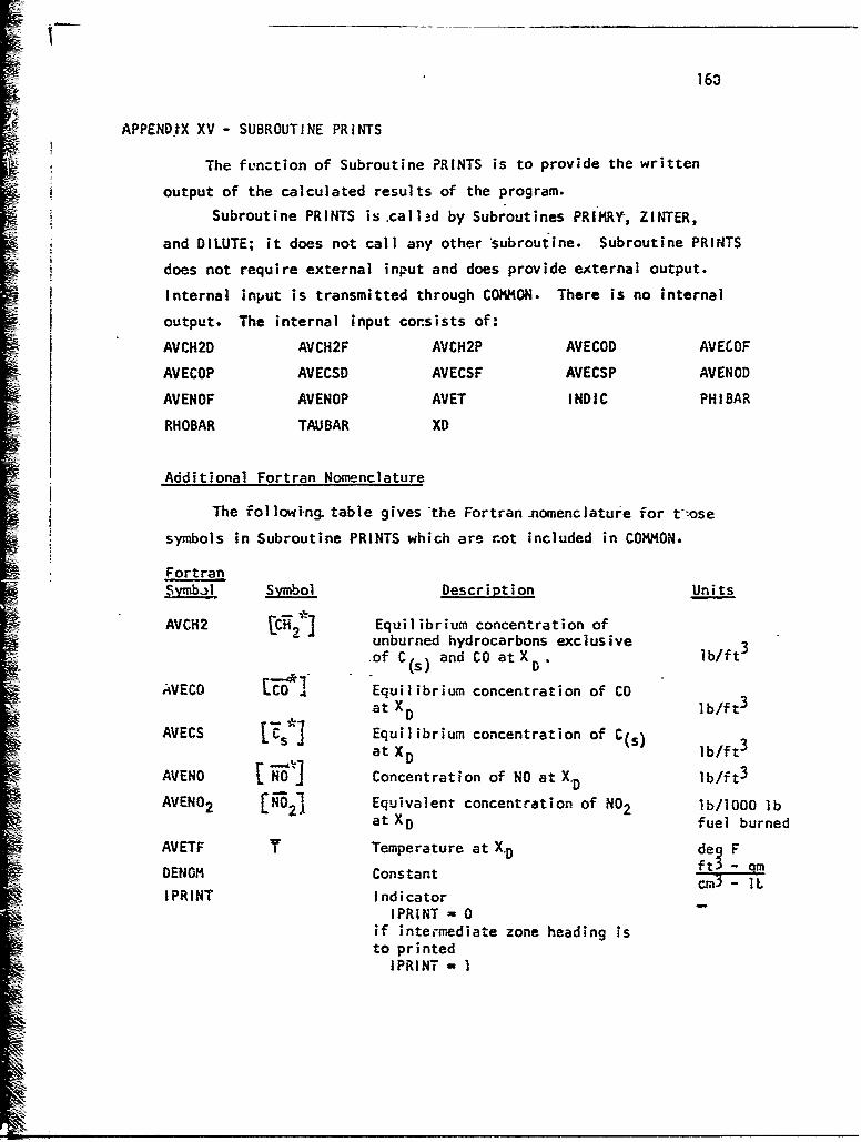
163
APPENDtX XV - SUBROUTI NE PR INTS
The function of Subroutine PRINTS is to provide the written
output of the calculated results of the program.
Subroutine PRINTS is .calld by Subroutines PRIMRY, ZINTER,
and DILUTE; it does not call any other 'subroutine. Subroutine PRINTS
does not require external input and does provide eAternal output.
Internal input is transmitted through COMMON. There is no internal
output. The internal input consists of:
AVCH2D AVCH2F AVCH2P AVECOD AVECOF
AVECOP AVECSD AVECSF AVECSP AVENOD
AVENOF AVENOP AVET INDIC PHIBAR
RHOBAR TAUBAR XD
Additional Fortran Nomenclature
The followi-ng table gives 'the Fortran nomenclature for t"ose
symbols in Subroutine PRINTS which are not included in COMMON.
Fortranjymbal Symbol Description Units
AVCH2 [C6i2 . Equilibrium concentration ofunburned hydrocarbons exclusive 3
of C(,) and CO atXD ,
AVECO EEO Equilibrium concentration of COat XD IWT D•
AVECS 1kI Equilibrium concentration of C(s)
at XD lb/ftS[ x.DAVENO NO Concentration of NO at X lb/ft3
AVEN0 2 LN-02 Equivalent concentration of NO2 lb/lOOO lbat XD fuel burned
AVETF T Temperature at X.D de• F
DENOM Constant 't. - IL
IPRINT IndicatorIPRINT - 0
if intermediate zone heading isto printed
IPRINT i 1

161
FortranSymbol j Description Units
if intermediate zone ;ieading is notto be printed
IPRINT - 2if dilutton zonL heading is not tobe printed
RHOBA Mean density of combustion products-XD lb/ft 3
TTUBAR Mean rt:idence time at X msecs
XOUT XD Axial position downstream in thecombustor in
Analysis Procedure
The step-by-step procedure of Subroutine PRINTS is given below.
The Fortran listing of the subroutine is presented at the conclusion
of the step-by-step procedure.
1. Convert XD from cm to in.
2. Convert•T- from secs to msecs.
3- Convert NO, CO, C(,), and CHI concentrations from gm/ccto lb/ft3.
4. Convert NO concentration at X.D to the equivalent NO2
concentration.
5. Convert f from gm/cc to lb/ft 3 .
6. Convert T from deg K to deg F.
7. If this is the primary zone, write the primary zone heading
and output. Go to step 12. if it is not the primary zone,
go to step 8.
8. If this is the intermediate zone and the first written
output for the zone, write the heading for the intermediate
zone. If not, go to step 9.
9. If this Is the intermediate zone, write the output atX 0.
Go to step 12. If it is not the intermediate zone, go to
step 10.
10. If this is the dilution zone and the first written output
in the zone, write the heading for the dilution zone. If
not, go to step 11.

162
11. If this is the dilution zone, write the output for the
dilutiot ;tone at XD. Go to step 12.
12. Return.
5-
I_ME

163
SUBROUTINE PRINTS PRT*o000REAL NO PRT*0 010ICOMMUN/OUT1/AVECSGAVECOG, AVCH2GAVECSPAVEC'OP, AVCH2PAVECSOAVECOPRT*0020
1D9AVCI42DtAVECSF9AVECOF9AVCm2F PRT*0030COMMON/OUT2/AVENOGAVENODAVENOPAVENOFAVENFURROILAST PRT*0040CODIMON/OUT3/INDICNO(50) ,AVETTAUBARRHOBARPHI8ARI'4AX,XD, PRT'005oIFBARDXULENTAUINTTAU.DILVELOC PRT*o060COMMON/OUT4/CONGNO(50) ,DELmD0(50) AREAOASLOPEDMFUOSLOPE(5L) ,TSLOPRT0 00701PENOP(50) ,EKKOOMFTUDM(50) .001(50), F8(50 ,014F1DtAIRDtOMFFEDPRT*00B02.RSU8ASIGSIGZERAVEMWOMDDA(50),OHODM(S0),OMDDP(50),OHODPP(50),FPRTOOO903PRIME(5O),NOEQXDANOsAUQOIFNO(5G),NOZERO(50),RDOT(50),E(50) PRT~o0ooNPRINT~o PRTcolloIF(IN51C.EQ-l) IPRINIuO PRT~ol2oXOUT=XD/2*54 PRT~ol30TTUHAR =TAUBAR*10OO. PRTO014-ODEN014 454;O*3o532E-'05 PRT*0150AVENO=AVENOD/DENOM PRT*G160AvEcO=AvECOO/DENOM PRT*O 170AVECS=AVECSD/LENOM PRT*0 180AVCH~zAVCH2D/DENOM PRT*o 190AVEN02 = AVENOF*46eO/30*0 PRT*0200RHOBA=RHORAR/DENOM PRT*0210AVETF= (AVET-273.16)*1*B)*32.0 PRT*0220Go TO (10009200093000),INDIC PRT*02'zn
1000 CONTINUE PRT*0240wRITE(6, 1010) PT05
1010 FORMAT(1Hj) PTo6WRITE(6*1020) PRT*0270
1020 FOHMAT(48H THIS IS THE MAIN PRINTOUT FOR THE PRIMARY ZONE Il/)PRT*o28oGO TO 4000 PRT*0290
2000 IF(IPRINT,EQ.1) 60 TO 5500 PRT*0300wRITE (6*1010) PRT'o31 0WRITEi6t2020) PRT*o320
2020 FO'94AT(53H THIS IS THE MAIN PRINTOUT FOR THE INJTERMEDIATE ZONE PRT*o3301/////) PRT*O34OI PR I NT1 PRT*O350GO TO 4000 PRT00360
3000 IF(IPR:NT.Eo.2) GO TO 5500 PRT*0370WRITEC69101O) PRT~o3BoWF.TE(6t.3020) PRT*039O
302-0 FOPCMAT(49H THIS IS THE MAIN PRINTOUT FOR THE DILUTION ZONE I////) PRT904001POINt=2 PRT-0410
4000 WRITE16t5000) PRT*o42o5000 FORMAT(1X.6HXCIN.) ,1X,3HPHI,3X,1HT,6X,3HRH0,3X,3HTAU,6Xs2HNO,9X,3HPRTQ0430
1N029 §Xs4HC(S), 6X94HC(S)t 8X,2HCO, 9X,2HCOt 8X93HCH29 8X#3HCH2 ) PRT*0 440wRITEC6,51o0) PRTOO450
f 5100 FO?~xAT(8X,4hAVE.,1X95HOE6 F.3Xt4HAVE.,2X,4HAVE.,5X,3HPP,4,6X,7HLBS PRT*046O1PER,7A,311PPM,5XTHLBS PER,Th,3mPPm95X97HLBS PER9 6Xs3HPPM97Xt7HLBSPRT*047o
2WRITE(695200) PRT*049O5200 FORMAT(19X,7HLR/CUFTt1X,4HMSEC,4X,5H(VOL),5XTH1OOO LtX5(O)PT0o
14X#7'11000 L8,6X,5H(VOL)t4X,7H1000 LBSX95H(VOL)s4Xt7H1000 LB) PRToo5loWRITE(695300) PRT*0520
5300 FORMAT(43Xt11HFUEL BURNEDi11XI1HFuEL BURNEO911X91IHFUEL 8URNED911?PRT~o53o1XI1IIFUEL BURNED) PRT~o54o
5500 WRITEC6,6000)XOUTtPHIBARAVETFRHOBATTU8ARAVENOPAVENO2,AVECSP, PRT*05501 AVECSF, AVECOP,AVE'O,AVCH2P tAVCH2F PRT*0560
6000 FORMAI(lX,F5.2,1X.F4.2,1XP5.0,1X9F6.4,1XF6.2,1Xtg(El0.3,1X),,)* PRT~o57oIFINPRINT.EQ.1) WA!TE(699999)( NO{I)vI31,IMAX) PRT@O5590
9999 FORMATQl0Xt4H **s8E12*4) PRT~o5go

164
PRT*0600
RETURN PRT*6610
END

165
APPENDIX XVI - METHOD OF CALCULATION OF AIR DISTRIBUTION CHARACTERISTICS
Air enters the combustor liner at discrete positions over the
whole length of the liner. The bulk of such flow normally enters
perpendicular to the direction of the mainstream product flow and
has then to be deflected and entrained before it can mix with the
combust-ion products. This action requires a finite time (i.e., dis-
tance) to occur, and its effect upon the nitric ox;de formation proc-
ess has to be cop:,tvered. A method has been developed, therefore,
to take account of this effect. The method is consistent with the
mixing assumption- made in the flow model described in this report
it has been applied to aNi combustors considered in this report and
j iis described below.
2 5 6
A ,X -0 X XL X - XEND
The flow behzavior et each port shown in the figure above is
assumed to behave as follows:•I Port I All air enterirg at this posit~on is assumed Le mix
with the products in the primary zone.
SPort 2 Some fraction of the air, f, mixes with the primary
zone and the remainder is entrained acco-ding to the
law described for port 4.

166
Port 3 Cooling air mixes according to the relationship
MX = M3 (Distance from port 3 to X dividedSby %Astance from port 3 toXL05
and that part which mixes before the primary zone
exit (X - 0), is assumed to burn in the primary zone.
9 Port 4
and 5 Both ccaling and combu.zion air mix according to the
relationship shown above,! i.e., MX - M4((X-Xit)/(XL-X4))0-5
Port 6
and 7 This air enters the dilution zone so it is assumed
that instantaneous mixing occurs (see Sectior. 2.5).
All these independent mass flows are then s1;nne¶d at a particular
position along the combustor to give the total airflow contained
with the combustion products at that poi it. For example:
air burning in the primary zone Mpz i's given by,
Mpz W io = Ml + fM2 + M3
air at position X (O4X4XL)
Mx = (1-f) M2 + M3x + M4x + M~x + Mpzair at position X, (X7 4X4-X6 )5r
Mx = _Mn + M7
This method was applied to combustors A and B studied in this
report and in each case the value of f, the fraction of air entering
the primary zone from the first row of air ports, was assumed to
equal one third. For Combu,.tor A this value corresponded to the
value recommended by the designers, but in the case of Combustor B,
the value was estimated based on the design features. Errors in the
predictions of nitric oxide em,,ssion leve;s from this latter estimate
can be expected to be negligible as the total airflow through port 2
represents less than two per cent of the total airflow.
I2