friction and wear of unlubricated nitihf with nitriding ... · the unlubricated tribological...
TRANSCRIPT

Malcolm K. StanfordGlenn Research Center, Cleveland, Ohio
Friction and Wear of Unlubricated NiTiHf With Nitriding Surface Treatments
NASA/TM—2018-219740
February 2018
https://ntrs.nasa.gov/search.jsp?R=20180001569 2019-05-23T18:10:51+00:00Z

NASA STI Program . . . in Profile
Since its founding, NASA has been dedicated to the advancement of aeronautics and space science. The NASA Scientific and Technical Information (STI) Program plays a key part in helping NASA maintain this important role.
The NASA STI Program operates under the auspices of the Agency Chief Information Officer. It collects, organizes, provides for archiving, and disseminates NASA’s STI. The NASA STI Program provides access to the NASA Technical Report Server—Registered (NTRS Reg) and NASA Technical Report Server—Public (NTRS) thus providing one of the largest collections of aeronautical and space science STI in the world. Results are published in both non-NASA channels and by NASA in the NASA STI Report Series, which includes the following report types: • TECHNICAL PUBLICATION. Reports of
completed research or a major significant phase of research that present the results of NASA programs and include extensive data or theoretical analysis. Includes compilations of significant scientific and technical data and information deemed to be of continuing reference value. NASA counter-part of peer-reviewed formal professional papers, but has less stringent limitations on manuscript length and extent of graphic presentations.
• TECHNICAL MEMORANDUM. Scientific
and technical findings that are preliminary or of specialized interest, e.g., “quick-release” reports, working papers, and bibliographies that contain minimal annotation. Does not contain extensive analysis.
• CONTRACTOR REPORT. Scientific and technical findings by NASA-sponsored contractors and grantees.
• CONFERENCE PUBLICATION. Collected papers from scientific and technical conferences, symposia, seminars, or other meetings sponsored or co-sponsored by NASA.
• SPECIAL PUBLICATION. Scientific,
technical, or historical information from NASA programs, projects, and missions, often concerned with subjects having substantial public interest.
• TECHNICAL TRANSLATION. English-
language translations of foreign scientific and technical material pertinent to NASA’s mission.
For more information about the NASA STI program, see the following:
• Access the NASA STI program home page at http://www.sti.nasa.gov
• E-mail your question to [email protected] • Fax your question to the NASA STI
Information Desk at 757-864-6500
• Telephone the NASA STI Information Desk at 757-864-9658 • Write to:
NASA STI Program Mail Stop 148 NASA Langley Research Center Hampton, VA 23681-2199

Malcolm K. StanfordGlenn Research Center, Cleveland, Ohio
Friction and Wear of Unlubricated NiTiHf With Nitriding Surface Treatments
NASA/TM—2018-219740
February 2018
National Aeronautics andSpace Administration
Glenn Research Center Cleveland, Ohio 44135
Acknowledgments
I am grateful for the generous technical assistance I received from J. A. Buehler, B. N. Cook, D. F. Johnson, R. A. Manco II, T. R. McCue, R. J. Pawlik, Dr. R. B. Rogers, K. H. Sirk, and F. Thomas, which made this study possible. I am also thankful for the helpful technical discussions with Drs. R. J. Bruckner, C. DellaCorte, T. L. Krantz and E. A. Rolinski. This study was funded by the Transformative Tools and Technologies (TTT) Project under NASA’s Aeronautics Research Mission Directorate.
Available from
Trade names and trademarks are used in this report for identification only. Their usage does not constitute an official endorsement, either expressed or implied, by the National Aeronautics and
Space Administration.
Level of Review: This material has been technically reviewed by technical management.
This report contains preliminary findings, subject to revision as analysis proceeds.
NASA STI ProgramMail Stop 148NASA Langley Research CenterHampton, VA 23681-2199
National Technical Information Service5285 Port Royal RoadSpringfield, VA 22161
703-605-6000
This report is available in electronic form at http://www.sti.nasa.gov/ and http://ntrs.nasa.gov/
This work was sponsored by the Transformative Aeronautics Concepts Program.
NASA/TM—2018-219740 1
Friction and Wear of Unlubricated NiTiHf With Nitriding Surface Treatments
Malcolm K. Stanford
National Aeronautics and Space Administration Glenn Research Center at Lewis Field
Cleveland, Ohio 44135
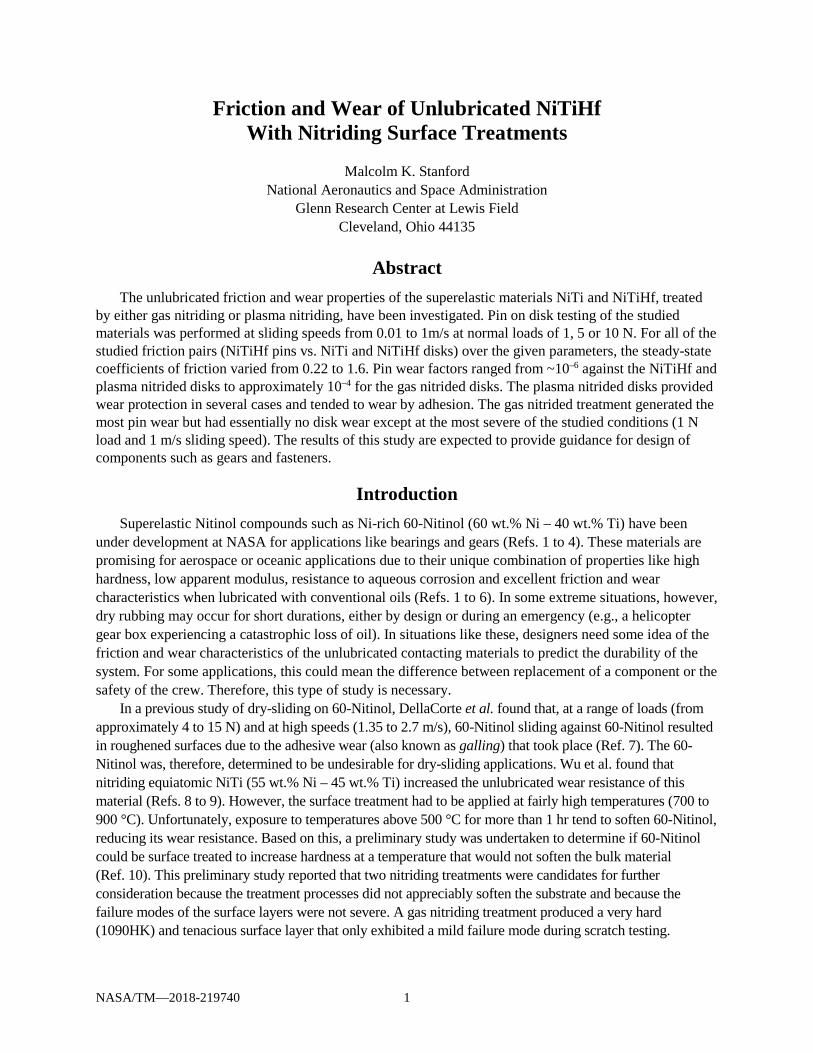
Abstract The unlubricated friction and wear properties of the superelastic materials NiTi and NiTiHf, treated
by either gas nitriding or plasma nitriding, have been investigated. Pin on disk testing of the studied materials was performed at sliding speeds from 0.01 to 1m/s at normal loads of 1, 5 or 10 N. For all of the studied friction pairs (NiTiHf pins vs. NiTi and NiTiHf disks) over the given parameters, the steady-state coefficients of friction varied from 0.22 to 1.6. Pin wear factors ranged from ~10–6 against the NiTiHf and plasma nitrided disks to approximately 10–4 for the gas nitrided disks. The plasma nitrided disks provided wear protection in several cases and tended to wear by adhesion. The gas nitrided treatment generated the most pin wear but had essentially no disk wear except at the most severe of the studied conditions (1 N load and 1 m/s sliding speed). The results of this study are expected to provide guidance for design of components such as gears and fasteners.
Introduction Superelastic Nitinol compounds such as Ni-rich 60-Nitinol (60 wt.% Ni – 40 wt.% Ti) have been
under development at NASA for applications like bearings and gears (Refs. 1 to 4). These materials are promising for aerospace or oceanic applications due to their unique combination of properties like high hardness, low apparent modulus, resistance to aqueous corrosion and excellent friction and wear characteristics when lubricated with conventional oils (Refs. 1 to 6). In some extreme situations, however, dry rubbing may occur for short durations, either by design or during an emergency (e.g., a helicopter gear box experiencing a catastrophic loss of oil). In situations like these, designers need some idea of the friction and wear characteristics of the unlubricated contacting materials to predict the durability of the system. For some applications, this could mean the difference between replacement of a component or the safety of the crew. Therefore, this type of study is necessary.
In a previous study of dry-sliding on 60-Nitinol, DellaCorte et al. found that, at a range of loads (from approximately 4 to 15 N) and at high speeds (1.35 to 2.7 m/s), 60-Nitinol sliding against 60-Nitinol resulted in roughened surfaces due to the adhesive wear (also known as galling) that took place (Ref. 7). The 60-Nitinol was, therefore, determined to be undesirable for dry-sliding applications. Wu et al. found that nitriding equiatomic NiTi (55 wt.% Ni – 45 wt.% Ti) increased the unlubricated wear resistance of this material (Refs. 8 to 9). However, the surface treatment had to be applied at fairly high temperatures (700 to 900 °C). Unfortunately, exposure to temperatures above 500 °C for more than 1 hr tend to soften 60-Nitinol, reducing its wear resistance. Based on this, a preliminary study was undertaken to determine if 60-Nitinol could be surface treated to increase hardness at a temperature that would not soften the bulk material (Ref. 10). This preliminary study reported that two nitriding treatments were candidates for further consideration because the treatment processes did not appreciably soften the substrate and because the failure modes of the surface layers were not severe. A gas nitriding treatment produced a very hard (1090HK) and tenacious surface layer that only exhibited a mild failure mode during scratch testing.

NASA/TM—2018-219740 2
However, the application of the surface treatment slightly roughened the surface and could increase wear of the counterface material. A plasma nitriding treatment also had a relatively mild failure mode (plastic deformation) with no cracking or delamination. Because the treatment layer was very thin, its durability was uncertain but the resultant surface was very smooth. The purpose of the present investigation is to evaluate the unlubricated tribological properties of 60-Nitinol surface treated by gas nitriding and plasma nitriding.
During the course of this investigation, there was a concurrent effort to develop Nitinol compounds with dilute concentrations of a third element (such as Hf or Zr) (Refs. 11 to 12). These ternary Nitinol compositions were found to be hardenable at heat treatment temperatures more than 100 °C lower than 60-Nitinol. Therefore, this investigation will include evaluation of tribological properties of plasma nitride and gas nitride surface treatments on the ternary material NiTiHf (57 wt.%Ni – 40 wt.% Ti – 3 wt.% Hf) as well as 60-Nitinol.
Procedures Ingots of Ni-Ti and Ni-Ti-Hf were obtained from Puris, LLC (Bruceton Mills, WV)1. The chemical
composition of the materials, as listed in Table I, were provided by the supplier. Cylindrical rider pins with hemispherical tip radii of approximately 3.2 mm and disks (55 mm diameter by 10 mm thick) were machined from NiTiHf. The pins and disks were hardened through heat treatment at 900 °C for 2 hr followed by water quenching. This heat treatment is designed to transform the material from its martensitic phase, which is relatively soft, to its austenitic phase, which is hard (Ref. 11). X-ray diffraction of the material using Cu Kα radiation and a 0.5 mm diameter collimator after this heat treatment confirmed that this heat treatment rendered the material in its desired hardened state, indicated by the predominant austenitic consistency of the material. One face of each heat treated disk was polished to a mirror finish using metallographic procedures beginning with planar grinding with SiC media and concluding with vibratory polishing with colloidal silica. The polished surfaces were subsequently treated by either plasma nitriding or gas nitriding (Refs. 13 to 14).
The plasma nitrided disks were heated to 540 °C in a gaseous mixture of N2 and H2 at a base pressure of 2.45 mbar. A plasma was formed, which consisted of positive ions (N2
+), electrons and neutral N2 molecules. The electrical potential that formed the plasma was used to drive the N2 molecules into the disk surface, which served as a cathode, creating the nitrided layer. The gas nitrided disks were heated to 570 °C for approximately 30 min in an ammonia (N2-rich) atmosphere (Refs. 15 to 16). The nitriding activation potential, Kn, is defined as
3
2
3 2NH
nH
pK
p=
where 3NHp is the partial pressure of ammonia and
2
3 2Hp is the partial pressure of hydrogen, was
(Refs. 17 to 18). For this study, Kn = 2.5 atm–1/2. A NiTi disk and a NiTiHf disk were left untreated to serve as baseline specimens.
TABLE I.—COMPOSITION OF SUBSTRATE MATERIALS USED IN THIS STUDY Material Measured composition,
wt.% Impurities,
ppm
60 wt.% Ni – 40 wt.% Ti 60.0 wt.% Ni 40.0 wt.% Ti No ternary element C (40), H (2), N (<100), O (410)
60.% Ni – 37 wt.% Ti – 3 wt.% Hf
57.16 wt.% Ni 39.60 wt.% Ti 3.24 wt.%Hf C (180), Fe (230), H (24), Mn (27), N (10), O (640)
1 Puris, LLC is now Carpenter Technology Corporation
NASA/TM—2018-219740 3
The rider and disk surfaces were scrubbed with a 5 µm levigated alumina slurry, followed by ultrasonic cleaning in ethyl alcohol. The disks were then rinsed with deionized water and dried with forced air. The average surface roughness of the untreated NiTiHf disk was Ra = 0.02 µm. The plasma nitride and gas nitride treatments rendered average surface roughness of 0.03 and 0.68 µm, respectively. The observed difference in surface roughness is expected. Plasma nitriding tends to result in chemisorption and limited implantation depth which does not significantly alter the surface of the substrate (Ref. 13). In contrast, gases and salts from gas nitriding tend to penetrate the surface more deeply, creating internal compositional variations that tend to result in increased surface roughness.
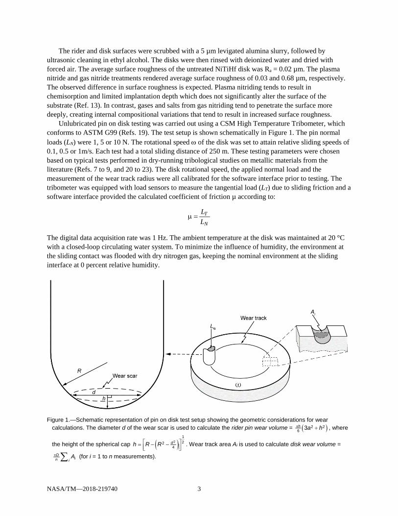
Unlubricated pin on disk testing was carried out using a CSM High Temperature Tribometer, which conforms to ASTM G99 (Refs. 19). The test setup is shown schematically in Figure 1. The pin normal loads (LN) were 1, 5 or 10 N. The rotational speed ω of the disk was set to attain relative sliding speeds of 0.1, 0.5 or 1m/s. Each test had a total sliding distance of 250 m. These testing parameters were chosen based on typical tests performed in dry-running tribological studies on metallic materials from the literature (Refs. 7 to 9, and 20 to 23). The disk rotational speed, the applied normal load and the measurement of the wear track radius were all calibrated for the software interface prior to testing. The tribometer was equipped with load sensors to measure the tangential load (LT) due to sliding friction and a software interface provided the calculated coefficient of friction µ according to:
T
N
LL
µ =
The digital data acquisition rate was 1 Hz. The ambient temperature at the disk was maintained at 20 °C with a closed-loop circulating water system. To minimize the influence of humidity, the environment at the sliding contact was flooded with dry nitrogen gas, keeping the nominal environment at the sliding interface at 0 percent relative humidity.
Figure 1.—Schematic representation of pin on disk test setup showing the geometric considerations for wear
calculations. The diameter d of the wear scar is used to calculate the rider pin wear volume = ( )π +2 26 3h a h , where
the height of the spherical cap ( ) = − − 2
122
4dh R R . Wear track area Ai is used to calculate disk wear volume =
π ∑Din i
A (for i = 1 to n measurements).

NASA/TM—2018-219740 4
To remove loose wear debris after testing, the pin and disk were cleaned in an ultrasonic bath with ethyl alcohol and dried with forced air. The volume of material worn was modeled as a spherical cap (see left side of Figure 1). Optical microscopy and digital image analysis software were used to measure the diameter of the wear scar. The resolution of the digital interface was approximately 3.2 µm/pixel. The average of two orthogonal, independent measurements of the wear scar diameter was used to calculate the volume of worn material, as described in the test standard (Ref. 19). Wear of the disk was determined using contact profilometry to measure the profile of each wear scar (see right side of Figure 1) in four radial locations, each 90° from the adjacent. The profile was then used to calculate the volume of wear (or material gained by adhesive transfer).
The wear volumes of both the pin and the disk were used to calculate Archard’s standard steady-state wear factor K for both members, given by
3N
HVKL S
=
using the Brinell hardness of the pin H, the measured wear volume V, the load normal to the surface LN and the distance slid S (Refs. 24 to 26). This metric is commonly used to allow direct comparison between tribological material pairs (or tribopairs) with various performance characteristics since the wear volume is normalized with respect to the applied load and sliding distance. A limitation of the metric is that it does not keep record of when material was transferred to (and, subsequently, removed from) a surface. Typically, and in the case of this study, the wear factor is measured after the test. Wear of metals typically occurs at a relatively high rate initially but then reduces significantly during the ensuing steady-state wear regime (Refs. 26). However, the linear variable differential transformer with which the tribometer was equipped was not functioning properly at the time of this study so the in-situ wear could not be measured. Therefore, the wear factor calculation included both the initial period, when wear occurred at a relatively high rate, and the steady-state period, when wear was essentially constant. Finally, to gain a better understanding of the nature of the wear that takes place during these tests, the surfaces of the tribopairs and the wear debris was examined with optical and scanning electron microscopy. Bulk material chemistry was analyzed by inductively-coupled plasma atomic emission spectroscopy (ICP-AES) while specimen surface chemistry was analyzed by energy dispersive x-ray spectroscopy (EDS) (Refs. 27 to 28).
Results and Discussion Friction
The coefficient of friction was measured throughout each test. The initial static friction F0 was the friction coefficient at the ordinate (when the test began). Friction rose steadily for the first stage of each test, traditionally designated the running-in period. An example of this is shown in Figure 2. During this interval, surface films on the friction pair were removed to expose fresh material and microscopic asperities were worn away to increase surface contact area, both phenomena contributing to the observed increase in friction (Refs. 29 and 30). Beyond this initial phase, the friction maintained a steady-state (constant) value, also denoted in Figure 2. This steady-state value, as well as the static friction, was reported for each of the studied friction pairs at the test conditions given in Table II. The nature of the friction curves is also noteworthy. The baseline and plasma nitrided friction traces (Figure 2(a) and (b)), are relatively jagged compared to the friction trace from the gas nitrided disk. These differences are likely due to the differences in the predominant friction mechanism, which will be discussed in the following section on wear. Friction coefficients ranged from approximately 0.7 to 1.6 for the treated specimens compared to 0.2 to 1.2 for the untreated disks.

NASA/TM—2018-219740 5
(a)
(b)
(c) Figure 2.—Typical friction measurements from (a) baseline NiTiHf disk, (b) plasma
nitrided disk and (c) gas nitrided disk. The baseline friction trace illustrates measurements of (i) static friction F0, (ii) run-in period and (iii) steady-state friction.
0
0.2
0.4
0.6
0.8
1
1.2
0 100 200 300 400
Coe
ffici
ent o
f fric
tion
Time, s
0
0.2
0.4
0.6
0.8
1
1.2
1.4
0 500 1000 1500 2000 2500
Coe
ffici
ent o
f fric
tion
Time, s
0
0.2
0.4
0.6
0.8
1
1.2
1.4
0 500 1000 1500 2000 2500
Coe
ffici
ent o
f fric
tion
Time, s
i
ii iii

NASA/TM—2018-219740 6
TABLE II.—STEADY-STATE FRICTION COEFFICIENTS FOR THE STUDIED FRICTION PAIRS (NiTiHf PIN)
Disk Load, N
Speed, m/s
F0 µ = FT/FN
NiTiHf 10 1 0.63 0.49 ± 0.07 NiTiHf 1 0.5 0.59 1.08 ± 0.09
NiTiHf 5 0.1 0.23 0.89 ± 0.10
NiTiHf 1 0.1 0.23 1.25 ± 0.11
NiTiHf 1 0.01 0.30 1.19 ± 0.13 NiTi 1 1 0.18 0.22 ± 0.01
NiTi 1 0.1 0.14 0.39 ± 0.03
Gas nitrided NiTiHf 10 1 0.31 0.72 ± 0.04
Gas nitrided NiTiHf 1 0.5 0.80 1.59 ± 0.08 Gas nitrided NiTiHf 5 0.1 0.38 0.86 ± 0.02
Gas nitrided NiTi 5 1 0.77 0.93 ± 0.03
Gas nitrided NiTi 1 1 0.54 1.49 ± 0.05
Gas nitrided NiTi 5 0.1 0.02 1.27 ± 0.04 Gas nitrided NiTi 1 0.1 0.52 1.39 ± 0.09
Plasma nitrided NiTiHf 10 1 0.10 0.68 ± 0.04
Plasma nitrided NiTiHf 1 1 0.20 1.03 ± 0.07
Plasma nitrided NiTiHf 1 0.5 0.16 1.10 ± 0.06 Plasma nitrided NiTiHf 5 0.1 0.05 0.76 ± 0.07
Plasma nitrided NiTiHf 1 0.01 0.10 1.29 ± 0.17
Plasma nitrided NiTi 5 1 0.14 0.88 ± 0.02 Plasma nitrided NiTi 5 0.1 0.49 1.24 ± 0.07
Plasma nitrided NiTi 1 0.1 0.16 1.56 ± 0.07
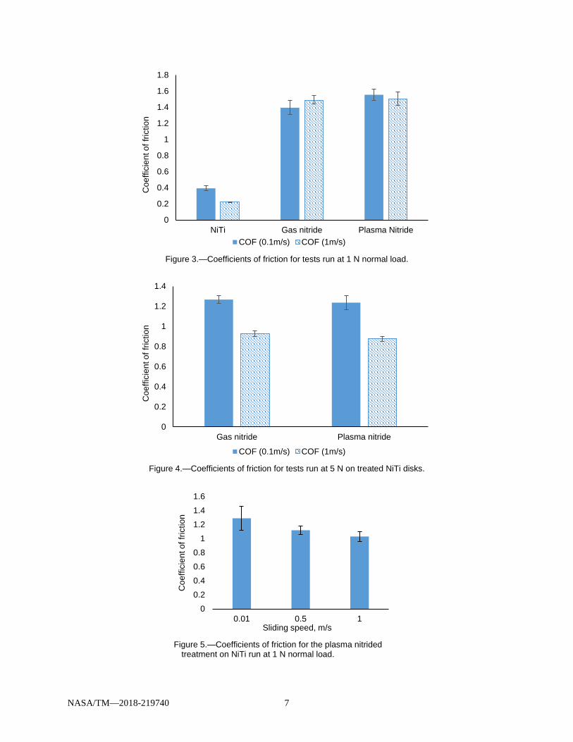
Figure 3 compares the friction coefficient for the untreated NiTi disk and the treated disks at a normal load of 1 N with respect to two sliding speeds (0.1 and 1.0 m/s). The data show that the coefficients of friction for the treated disks are significantly higher than the baseline disk at both speeds. The data also indicate a slight decrease in friction with increased sliding speed for the untreated disk but essentially no change in friction for the treated disks with respect to sliding speed. Figure 4 compares the friction coefficient for treated disks at 5 N with respect to two sliding speeds (0.1 and 1.0 m/s). These results clearly show a decrease in friction with increasing sliding speed. Figure 5 also shows that average coefficients of friction for tests run at 1 N on the plasma nitrided disk decreased slightly with increasing sliding speed. The apparent inverse correlation between sliding speed and friction shown in these examples was expected and has been noted in previous research (Ref. 31). A surprising finding, however, was that the untreated NiTi material has much lower friction than the treated disks. In fact, the measured friction values for the untreated disk (ranging from 0.2 to 0.4) are unusually low for any type of metal-on-metal sliding contact, not to mention NiTi-on-NiTi in dry sliding contact for which average coefficients of friction vary from approximately 0.6 to 0.8 (Refs. 32 and 33). Low coefficients of friction have also been reported in another recent study of unlubricated NiTi tribology (Ref. 7). This study attributes this result to the inverse relationship between coefficient of friction and sliding speed cited previously. However, the test of untreated NiTi at 1 N and 0.1 m/s (a relatively low speed) had a relatively low coefficient of friction (approximately 0.4). So, it seems that sliding speed alone does not fully account for the lower
NASA/TM—2018-219740 7
Figure 3.—Coefficients of friction for tests run at 1 N normal load.
Figure 4.—Coefficients of friction for tests run at 5 N on treated NiTi disks.
Figure 5.—Coefficients of friction for the plasma nitrided
treatment on NiTi run at 1 N normal load.
0
0.2
0.4
0.6
0.8
1
1.2
1.4
1.6
1.8
NiTi Gas nitride Plasma Nitride
Coe
ffici
ent o
f fric
tion
COF (0.1m/s) COF (1m/s)
0
0.2
0.4
0.6
0.8
1
1.2
1.4
Gas nitride Plasma nitride
Coe
ffici
ent o
f fric
tion
COF (0.1m/s) COF (1m/s)
0
0.2
0.4
0.6
0.8
1
1.2
1.4
1.6
0.01 0.5 1
Coe
ffici
ent o
f fric
tion
Sliding speed, m/s

NASA/TM—2018-219740 8
coefficients of friction observed in these tests. This phenomenon could be due to the superelastic effect observed in 60-Nitinol. In other research, the reduction of wear in 60-Nitinol was said to be due to the low ratio of apparent elastic modulus to hardness (Refs. 20, 34 to 37). Friction is the resistance to the relative motion of two surfaces caused by contact between microscopic asperities on opposing surfaces. If the contact stress is high enough, the asperities can transform from their hardened austenitic phase to the softer martensitic phase, which has less resistance to deformation. This softer asperity would then have less resistance to opposing motion and result in a lower local friction. This mechanism repeated over a large area would result in a lower overall friction coefficient. This explanation is speculative but the reduced friction that has been observed should be investigated further.
Figure 6 and Figure 7 compare the friction of treated and untreated NiTiHf disks at various loads and speeds. At low speeds, there is not much separation between the results of material pairs run at similar conditions. At 1 N (see Figure 6), the friction coefficient varies between 1.8 and 1.5 for tests run 0.01 and 0.5 m/s. For tests run at 5 or 10 N (see Figure 7), the friction coefficient varies from approximately 0.7 to 0.9 except for the baseline test run at 1 m/s. In this case, the coefficient of friction (approximately 0.5) is noticeably lower than the values obtained from other tests. This value may not be remarkable when considered in isolation, but when considered in the context of the relatively low friction noted for NiTi disks run at 1 N load, this phenomenon should be studied in more detail in the future. Nevertheless, friction should be considered along with wear, which is the subject of the following section.
Figure 6.—Friction for NiTiHf disks with and without surface treatment run at 1 N.
Figure 7.—Friction for NiTiHf disks at various test conditions.
00.20.40.60.8
11.21.41.61.8
NiTiHf Gas nitride Plasma Nitride
Coe
ffici
ent o
f fric
tion
COF (1N;0.01m/s) COF (1N;0.5m/s)
0
0.2
0.4
0.6
0.8
1
1.2
NiTiHf Gas nitride Plasma Nitride
Coe
ffici
ent o
f fric
tion
COF (5N;0.1m/s) COF (10N;1m/s)

NASA/TM—2018-219740 9
(a) (b)
(c)
Figure 8.—Optical micrographs of typical wear scars on NiTiHf pins after running against (a) baseline NiTiHf disk, (b) plasma nitrided NiTiHf disk and (c) gas nitrided NiTiHf disk. Each test was performed at 5 N load and 0.1 m/s sliding speed. Arrows in (a) and (b) indicate some areas where material has been removed by adhesion. The disk sliding direction (SD), as indicated in Figure 6(a), has the same orientation in each image. Each pin has grooves parallel to the sliding direction, which indicates abrasive wear.
Wear
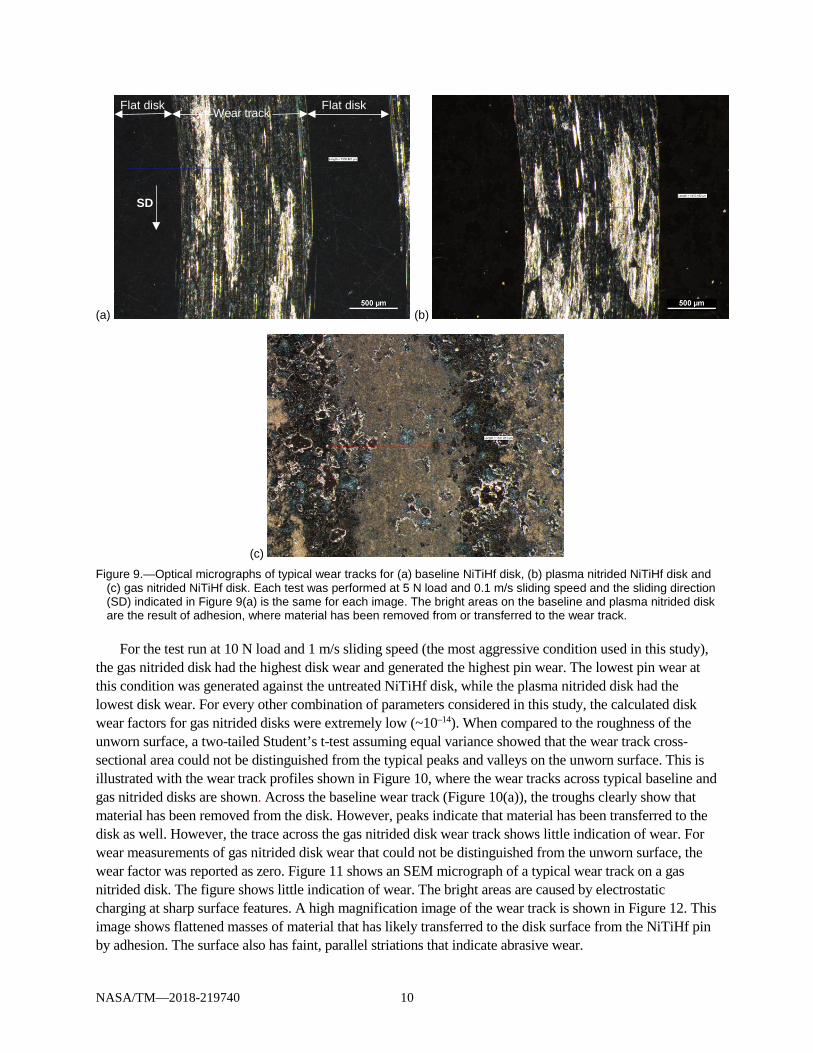
Pin wear resulted in a characteristic circular wear scar on the pin. Examples of typical wear scars are shown in Figure 8. The surface morphology of these wear scars gives an indication of the wear mechanisms that were in operation. For the baseline and plasma nitrided disks, clear signs of adhesive wear could be seen along the trailing edge of the pins, where chunks of material were removed as they adhered to the disk (see Figure 8(a) to 8(b)). Each pin also had grooves parallel to the sliding direction that indicated abrasive wear (Figure 8(a) to 8(c)). The pin wear factor from each test was listed in Table III. Figure 9 shows optical micrographs of typical wear tracks after testing treated and untreated surfaces. The disk wear factors are also listed in Table III. These values were typical for unlubricated materials (Refs. 24 and 31). A negative wear factor value indicates material removal, while a positive value indicates adhesive transfer onto the subject specimen from the counterface material.
SD
NASA/TM—2018-219740 10
(a) (b)
(c) Figure 9.—Optical micrographs of typical wear tracks for (a) baseline NiTiHf disk, (b) plasma nitrided NiTiHf disk and
(c) gas nitrided NiTiHf disk. Each test was performed at 5 N load and 0.1 m/s sliding speed and the sliding direction (SD) indicated in Figure 9(a) is the same for each image. The bright areas on the baseline and plasma nitrided disk are the result of adhesion, where material has been removed from or transferred to the wear track.
For the test run at 10 N load and 1 m/s sliding speed (the most aggressive condition used in this study),
the gas nitrided disk had the highest disk wear and generated the highest pin wear. The lowest pin wear at this condition was generated against the untreated NiTiHf disk, while the plasma nitrided disk had the lowest disk wear. For every other combination of parameters considered in this study, the calculated disk wear factors for gas nitrided disks were extremely low (~10–14). When compared to the roughness of the unworn surface, a two-tailed Student’s t-test assuming equal variance showed that the wear track cross-sectional area could not be distinguished from the typical peaks and valleys on the unworn surface. This is illustrated with the wear track profiles shown in Figure 10, where the wear tracks across typical baseline and gas nitrided disks are shown. Across the baseline wear track (Figure 10(a)), the troughs clearly show that material has been removed from the disk. However, peaks indicate that material has been transferred to the disk as well. However, the trace across the gas nitrided disk wear track shows little indication of wear. For wear measurements of gas nitrided disk wear that could not be distinguished from the unworn surface, the wear factor was reported as zero. Figure 11 shows an SEM micrograph of a typical wear track on a gas nitrided disk. The figure shows little indication of wear. The bright areas are caused by electrostatic charging at sharp surface features. A high magnification image of the wear track is shown in Figure 12. This image shows flattened masses of material that has likely transferred to the disk surface from the NiTiHf pin by adhesion. The surface also has faint, parallel striations that indicate abrasive wear.
SD
Flat disk Flat disk Wear track

NASA/TM—2018-219740 11
(a)
(b) Figure 10.—Typical disk wear scar profiles of (a) baseline disk (b) gas nitrided disk, each run at
5 N and 0.1 m/s. Note that the wear track area of the gas nitrided disk is visually indistinguishable from the unworn area.
Wear track
Unworn area Unworn area

NASA/TM—2018-219740 12
TABLE III.—MEASURED WEAR Disk Load,
N Speed,
m/s Kpin Kdisk
NiTiHf 10 1 –2.8×10⁻⁶ –2.9×10⁻³
NiTiHf 1 0.5 –1.5×10⁻⁵ 4.3×10⁻³
NiTiHf 5 0.1 –4.4×10⁻⁵ 1.9×10⁻⁴
NiTiHf 1 0.1 –2.3×10⁻⁴ –2.5×10⁻²
NiTiHf 1 0.01 –2.8×10⁻⁴ 6.4×10⁻⁴
NiTi 1 1 –9.7×10⁻⁴ –2.9×10⁻³
NiTi 1 0.1 –2.5×10⁻⁴ –2.8×10⁻³
Gas nitrided NiTiHf 10 1 –3.7×10⁻⁴ –8.4×10⁻¹
Gas nitrided NiTiHf 1 0.5 –5.5×10⁻⁴ 0
Gas nitrided NiTiHf 5 0.1 –4.4×10⁻⁴ 0
Gas nitrided NiTi 5 1 –1.1×10⁻⁴ 0
Gas nitrided NiTi 1 1 –5.4×10⁻⁴ 0
Gas nitrided NiTi 5 0.1 –3.0×10⁻⁴ 0
Gas nitrided NiTi 1 0.1 –6.6×10⁻⁴ 0
Plasma nitrided NiTiHf 10 1 –8.3×10⁻⁶ –3.7×10⁻⁴
Plasma nitrided NiTiHf 1 1 –2.5×10⁻⁵ –5.8×10⁻⁴
Plasma nitrided NiTiHf 1 0.5 –4.2×10⁻⁵ 1.3×10⁻⁴
Plasma nitrided NiTiHf 5 0.1 –5.3×10⁻⁶ –9.2×10⁻⁴
Plasma nitrided NiTiHf 1 0.01 –9.5×10⁻⁶ 4.3×10⁻⁵
Plasma nitrided NiTi 5 1 –5.9×10⁻⁵ –1.2×10⁻²
Plasma nitrided NiTi 5 0.1 –3.5×10⁻⁵ –3.8×10⁻³
Plasma nitrided NiTi 1 0.1 –1.1×10⁻⁵ 1.5×10⁻²
*Positive disk wear means material has transferred to the disk from the pin to the disk.

NASA/TM—2018-219740 13
Figure 11.—SEM micrograph of a typical gas nitrided NiTi disk wear track showing very little
indication of wear. The sliding direction (SD) is indicated with an arrow. The highlighted area within the wear track is analyzed further in Figure 12.
SD

NASA/TM—2018-219740 14
(a)
(b) Figure 12.—X-ray analysis of a typical gas nitrided wear track. The spectra from the image
at a indicate the presence of Ni, Ti, O and N, which are expected, along with negligible amounts of contaminant elements. The image at b shows masses of material that are primarily composed of Ni, Ti and Hf and appear to have been deformed plastically along the sliding direction.

NASA/TM—2018-219740 15
(c)
(d)
(e) Figure 12.—Concluded.
NASA/TM—2018-219740 16
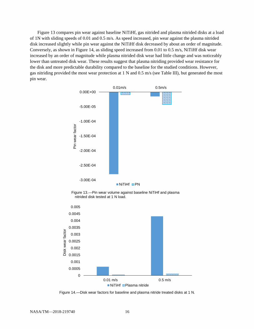
Figure 13 compares pin wear against baseline NiTiHf, gas nitrided and plasma nitrided disks at a load of 1N with sliding speeds of 0.01 and 0.5 m/s. As speed increased, pin wear against the plasma nitrided disk increased slightly while pin wear against the NiTiHf disk decreased by about an order of magnitude. Conversely, as shown in Figure 14, as sliding speed increased from 0.01 to 0.5 m/s, NiTiHf disk wear increased by an order of magnitude while plasma nitrided disk wear had little change and was noticeably lower than untreated disk wear. These results suggest that plasma nitriding provided wear resistance for the disk and more predictable durability compared to the baseline for the studied conditions. However, gas nitriding provided the most wear protection at 1 N and 0.5 m/s (see Table III), but generated the most pin wear.
Figure 13.—Pin wear volume against baseline NiTiHf and plasma
nitrided disk tested at 1 N load.
Figure 14.—Disk wear factors for baseline and plasma nitride treated disks at 1 N.
-3.00E-04
-2.50E-04
-2.00E-04
-1.50E-04
-1.00E-04
-5.00E-05
0.00E+000.01m/s 0.5m/s
Pin
wea
r fac
tor
NiTiHf PN
0
0.0005
0.001
0.0015
0.002
0.0025
0.003
0.0035
0.004
0.0045
0.005
0.01 m/s 0.5 m/s
Dis
k w
ear f
acto
r
NiTiHf Plasma nitride
NASA/TM—2018-219740 17
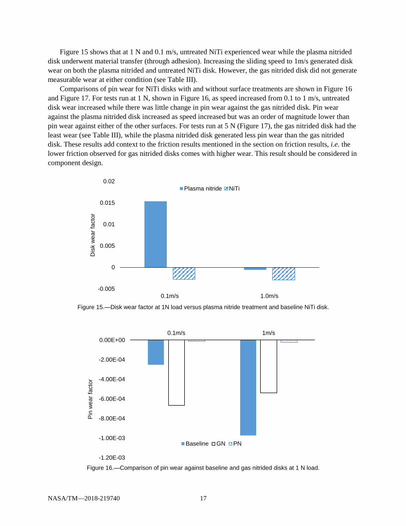
Figure 15 shows that at 1 N and 0.1 m/s, untreated NiTi experienced wear while the plasma nitrided disk underwent material transfer (through adhesion). Increasing the sliding speed to 1m/s generated disk wear on both the plasma nitrided and untreated NiTi disk. However, the gas nitrided disk did not generate measurable wear at either condition (see Table III).
Comparisons of pin wear for NiTi disks with and without surface treatments are shown in Figure 16 and Figure 17. For tests run at 1 N, shown in Figure 16, as speed increased from 0.1 to 1 m/s, untreated disk wear increased while there was little change in pin wear against the gas nitrided disk. Pin wear against the plasma nitrided disk increased as speed increased but was an order of magnitude lower than pin wear against either of the other surfaces. For tests run at 5 N (Figure 17), the gas nitrided disk had the least wear (see Table III), while the plasma nitrided disk generated less pin wear than the gas nitrided disk. These results add context to the friction results mentioned in the section on friction results, i.e. the lower friction observed for gas nitrided disks comes with higher wear. This result should be considered in component design.
Figure 15.—Disk wear factor at 1N load versus plasma nitride treatment and baseline NiTi disk.
Figure 16.—Comparison of pin wear against baseline and gas nitrided disks at 1 N load.
-0.005
0
0.005
0.01
0.015
0.02
0.1m/s 1.0m/s
Dis
k w
ear f
acto
r
Plasma nitride NiTi
-1.20E-03
-1.00E-03
-8.00E-04
-6.00E-04
-4.00E-04
-2.00E-04
0.00E+000.1m/s 1m/s
Pin
wea
r fac
tor
Baseline GN PN

NASA/TM—2018-219740 18
Figure 17.—Comparison of pin wear factors at 5N load.
Several fundamental wear mechanisms have been identified to describe the type of wear that occurs when surfaces are in contact (Refs. 25 and 39). These mechanisms are described schematically in Figure 18. Adhesive wear occurs after one surface becomes metallurgically bonded to the other and is then pulled away. This often results in fracture of the material perpendicular to the sliding direction (Ref. 40). Abrasive wear takes place when one surface plastically deforms the other through some cutting or plowing action (Ref. 41). This usually leaves grooves on the surface that run parallel to the sliding direction. Fatigue wear occurs when a cyclic load leads to fracture below the surface. Fatigue wear of 60-Nitinol results in a characteristic chevron pattern on the fracture surface indicating brittle fracture, as has been discussed in previous work (Refs. 42 to 44). Oxidative wear takes place when frictional heating results in oxidation at the surface and the oxidized material is worn away. Some magnification is needed to carefully inspect the surfaces and wear debris to be able to classify the wear mechanisms that are taking place. More than one mechanism may be active but identifying the predominant mechanism would still be useful to guide material selection or to drive design changes for improved component durability. The following is a discussion of the results of scanning electron microscopy (SEM) on selected wear surfaces and wear debris particles from this study.
SEM micrographs of the wear track on the untreated NiTiHf disk after testing at 5 N and 0.1 m/s are shown in Figure 19. This wear track showed signs of both adhesive wear (where it appears that the material has been plastically deformed and, in some locations, pulled away from the surface) and possibly abrasive wear mechanisms, as evidenced by parallel grooves along the sliding direction. SEM micrographs of a wear track on the plasma nitrided disk, as seen in Figure 20, show indications of material transfer to the wear track by the adhesive wear mechanism. It is noteworthy that, while the NiTiHf disk shows signs of adhesive wear from the disk, the plasma nitrided disk shows indications of adhesive transfer from the pin. Therefore, it appears that the plasma nitride treatment provides some protection from adhesive wear compared to the untreated surface. Adhesive wear is an undesirable wear mechanism for certain sliding systems like machine screw threads because the transferred material tends to form protrusions on the mating surface, increasing roughness and reducing clearance between the two surfaces, which can lead to seizure (Ref. 45). An interesting topic for a future study would be sliding friction of symmetric plasma nitrided systems (plasma nitrided NiTiHf versus plasma nitrided NiTiHf).
-3.50E-04
-3.00E-04
-2.50E-04
-2.00E-04
-1.50E-04
-1.00E-04
-5.00E-05
0.00E+000.1m/s 1m/s
Kpi
n, m
m3 /N
·m
PN GN

NASA/TM—2018-219740 19
Figure 18.—Fundamental wear mechanisms (Refs. 25).

NASA/TM—2018-219740 20
(a)
(b)
(c) Figure 19.—SEM micrographs at (a) low, (b) intermediate and
(c) high magnification of wear track on baseline NiTiHf disk after testing at 0.1 m/s sliding speed and 5 N normal load. Grooves parallel to the sliding direction (SD) due to abrasive wear can be seen in a and b, while fracture surfaces oriented parallel to the sliding direction, indicative of adhesive wear, are highlighted with arrows in c.
SD

NASA/TM—2018-219740 21
(a)
(b)
Figure 20.—SEM micrographs at (a) lower and (b) higher magnification of wear track on plasma nitrided disk after testing at 0.1 m/s sliding speed and 5 N normal load with the sliding direction (SD) indicated in (a). Adhesively-bonded wear debris, indicated with arrows in (a), is present on the wear track.
The wear debris from the plasma nitrided NiTiHf disk test at 0.1 m/s sliding speed and 5 N normal
load had the appearance of shiny flakes by visual inspection. SEM micrographs of this debris, as seen in Figure 21, showed that it was composed of flattened, irregularly-shaped particles (approximately 50 to 200 µm), consistent with the morphology of the adhesively transferred material in the wear track (see Figure 20). The particles were elongated along the sliding direction, a clear indicator of plastic deformation, and mildly striated, likely due to some combination of plastic deformation and abrasion. The SEM micrographs of the debris generally have the same greyscale value, indicating the similarity in their chemical compositions. The EDS spectrum from one of the particles (see Figure 21(b)), showed that it was composed of Ni, Ti and Hf, indicating that the material originated from the pin.
SD

NASA/TM—2018-219740 22
(a)
(b) Figure 21.—Wear debris from plasma nitrided NiTiHf disk test at 0.1 m/s and 5 N.
The SEM micrographs at (a) lower and (b) higher magnifications show flattened, irregularly-shaped particles, primarily composed of Ni, Ti and Hf. The morphology of the wear debris indicates adhesive wear.
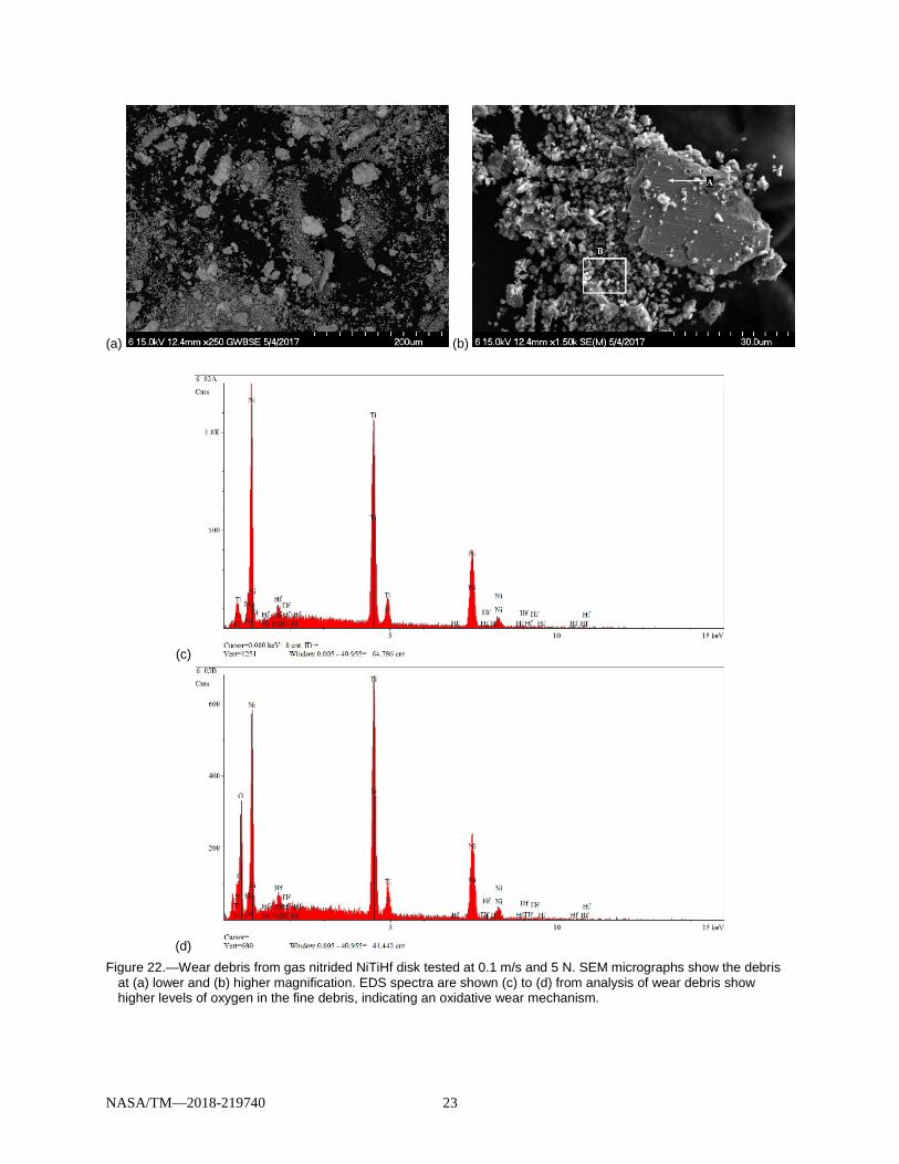
Visually, the wear debris from the gas nitrided NiTiHf disk tested at 0.1 m/s sliding speed and 5 N
load was black and powdery with a few larger, shiny particles interspersed within it. This debris was examined microscopically and some representative SEM micrographs are shown in Figure 22. The backscattered electron images emphasize the atomic number contrast between the larger (approximately 20 to 50 µm) irregularly-shaped particles and the fine (approximately 1 to 3 µm) particles, which contain elements with lower atomic weight (based on the fact that they appear darker in the micrograph). Regions of the larger debris particles adjacent to the wear surface also indicated the presence of lighter elements. EDS analysis (Figure 22(c) to (d)) showed that the lighter element was oxygen, indicating that oxidative wear lead to the generation of this fine wear debris (Refs. 21, 25, 36, and 37). The larger flakes are composed of NiTiHf, originating from the pin and indicating adhesive wear, based on their blocky and somewhat flattened morphology.
NASA/TM—2018-219740 23
(a) (b)
(c)
(d) Figure 22.—Wear debris from gas nitrided NiTiHf disk tested at 0.1 m/s and 5 N. SEM micrographs show the debris
at (a) lower and (b) higher magnification. EDS spectra are shown (c) to (d) from analysis of wear debris show higher levels of oxygen in the fine debris, indicating an oxidative wear mechanism.

NASA/TM—2018-219740 24
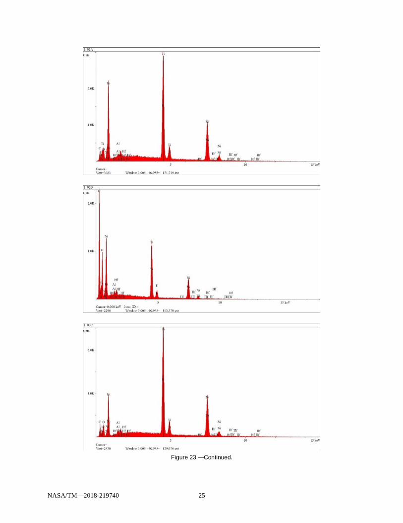
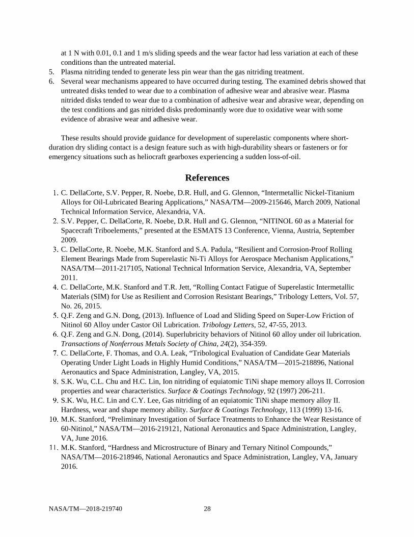
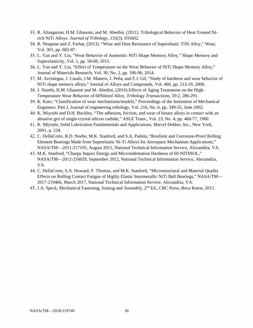
SEM micrographs and chemical analyses of wear debris collected after tests run at 0.1 m/s and 1N are shown in Figure 23. For pins run against the gas nitride treatment, the presence of fine, oxygen-rich particles indicates that the predominant wear mechanism was oxidative wear. The presence of blocky and somewhat flattened NiTiHf particles indicates adhesive wear of the pin on the plasma nitrided disk.
(a)
(b) Figure 23.—Wear debris after tests at 0.1 m/s and 1 N (NiTiHf substrate). The wear debris from the plasma nitrided
debris indicates adhesive wear, while the gas nitriding treatment indicates oxidative wear.
NASA/TM—2018-219740 25
Figure 23.—Continued.

NASA/TM—2018-219740 26
Figure 23.—Concluded.
(a) (b) Figure 24.—Wear debris particles generated during testing at 1 m/s and 1 N with NiTi disks against (a) plasma
nitrided and (b) gas nitrided disk treatments. For treated NiTi disks tested at 1 m/s and 1 N, the wear particles had irregular shapes with surface
striations. This morphology suggests that the particles were also generated through a combination of adhesion and abrasion. A particle from the plasma nitride treated test, shown in Figure 24(a), is composed of NiTiHf (likely originating from the pin). A particle from the gas nitride treated test, shown in Figure 24(b), was composed of NiTi (likely originating from the disk). Increasing the load to 5 N, some of the debris generated from the plasma nitride treatment has the appearance of long, continuous particles that resemble machining chips produced by a machining tool, as shown in Figure 24. This particle morphology is due to abrasion. Other debris had morphology consistent with adhesive wear (see Figure 25(d)).

NASA/TM—2018-219740 27
(a) (b)
(c) (d)
Figure 25.—Wear debris particles from (a) to (c) plasma nitrided and (d) gas nitrided NiTi disks testing performed at 1 m/s and 5 N. The long, continuous wear debris from the plasma nitrided disk indicate abrasive wear of the disk (like machining chips indicate ploughing wear, a type of abrasive wear) and blocky particles indicating adhesive wear of the pin. The gas nitrided treatment wear debris is blocky and indicates adhesive wear of the pin.
Conclusions The friction and wear characteristics of two superelastic alloys, NiTi (60 wt.% Ni – 40 wt.% Ti) and
NiTiHf (57.2 wt.% Ni – 39.6 wt.% Ti – 3.2 wt.% Hf) treated by either gas nitriding NiTiHf or plasma nitriding were studied using pin on disk testing. The results of this investigation showed:
1. The friction coefficient for untreated disks ranged from 0.2 to 1.1, while the friction coefficients for
the treated disks were slightly higher (ranging from approximately 0.7 to 1.6). 2. The plasma nitride treatment gave more erratic friction than the baseline while gas nitriding had more
stable friction versus time. 3. The gas nitriding treatment prevented wear of the disk for each of the studied test parameters except
the most severe (10 N and 1 m/s). Gas nitriding also generated the most pin wear for each of the studied test parameters except the most severe, where untreated NiTiHf and plasma nitrided disks had lower pin wear.
4. Plasma nitriding provided more disk wear protection than the untreated disks at 1N load at the range of speeds considered in this study. This treatment generated less pin wear than the untreated material
NASA/TM—2018-219740 28
at 1 N with 0.01, 0.1 and 1 m/s sliding speeds and the wear factor had less variation at each of these conditions than the untreated material.
5. Plasma nitriding tended to generate less pin wear than the gas nitriding treatment. 6. Several wear mechanisms appeared to have occurred during testing. The examined debris showed that
untreated disks tended to wear due to a combination of adhesive wear and abrasive wear. Plasma nitrided disks tended to wear due to a combination of adhesive wear and abrasive wear, depending on the test conditions and gas nitrided disks predominantly wore due to oxidative wear with some evidence of abrasive wear and adhesive wear. These results should provide guidance for development of superelastic components where short-
duration dry sliding contact is a design feature such as with high-durability shears or fasteners or for emergency situations such as heliocraft gearboxes experiencing a sudden loss-of-oil.
References C. DellaCorte, S.V. Pepper, R. Noebe, D.R. Hull, and G. Glennon, “Intermetallic Nickel-Titanium Alloys for Oil-Lubricated Bearing Applications,” NASA/TM—2009-215646, March 2009, National Technical Information Service, Alexandria, VA.
S.V. Pepper, C. DellaCorte, R. Noebe, D.R. Hull and G. Glennon, “NITINOL 60 as a Material for Spacecraft Triboelements,” presented at the ESMATS 13 Conference, Vienna, Austria, September 2009.
C. DellaCorte, R. Noebe, M.K. Stanford and S.A. Padula, “Resilient and Corrosion-Proof Rolling Element Bearings Made from Superelastic Ni-Ti Alloys for Aerospace Mechanism Applications,” NASA/TM—2011-217105, National Technical Information Service, Alexandria, VA, September 2011.
C. DellaCorte, M.K. Stanford and T.R. Jett, “Rolling Contact Fatigue of Superelastic Intermetallic Materials (SIM) for Use as Resilient and Corrosion Resistant Bearings,” Tribology Letters, Vol. 57, No. 26, 2015.
Q.F. Zeng and G.N. Dong, (2013). Influence of Load and Sliding Speed on Super-Low Friction of Nitinol 60 Alloy under Castor Oil Lubrication. Tribology Letters, 52, 47-55, 2013.
Q.F. Zeng and G.N. Dong, (2014). Superlubricity behaviors of Nitinol 60 alloy under oil lubrication. Transactions of Nonferrous Metals Society of China, 24(2), 354-359.
C. DellaCorte, F. Thomas, and O.A. Leak, “Tribological Evaluation of Candidate Gear Materials Operating Under Light Loads in Highly Humid Conditions,” NASA/TM—2015-218896, National Aeronautics and Space Administration, Langley, VA, 2015.
S.K. Wu, C.L. Chu and H.C. Lin, Ion nitriding of equiatomic TiNi shape memory alloys II. Corrosion properties and wear characteristics. Surface & Coatings Technology, 92 (1997) 206-211.
S.K. Wu, H.C. Lin and C.Y. Lee, Gas nitriding of an equiatomic TiNi shape memory alloy II. Hardness, wear and shape memory ability. Surface & Coatings Technology, 113 (1999) 13-16.
M.K. Stanford, “Preliminary Investigation of Surface Treatments to Enhance the Wear Resistance of 60-Nitinol,” NASA/TM—2016-219121, National Aeronautics and Space Administration, Langley, VA, June 2016.
M.K. Stanford, “Hardness and Microstructure of Binary and Ternary Nitinol Compounds,” NASA/TM—2016-218946, National Aeronautics and Space Administration, Langley, VA, January 2016.

NASA/TM—2018-219740 29
B.C. Hornbuckle, R.D. Noebe, and G.B. Thompson, Influence of Hf Solute Additions on the Precipitation and Hardenability in Ni-rich NiTi Alloys, Journal of Alloys and Compounds, Vol. 640, pp. 449–54, 2015.
E. Rolinski, “Mechanism of high-temperature plasma nitriding of titanium,” Materials Science and Engineering, Vol. 100, pp. 193–99, 1988.
G. Krauss, “Physical Metallurgy and the Heat Treatment of Steel,” in Metals Handbook Desk Edition, Chapter 28: Heat Treating, American Society for Metals, Metals Park, OH, 1985.
E.J. Mittemeijer, “Fundamentals of Nitriding and Nitrocarburizing,” in ASM Handbook, Volume 4A, Steel Heat Treating Fundamentals and Processes, J. Dossett and G.E. Totten, editors, 2013.
L. Liu, F. Ernst, G.M. Michal, and A.H. Heuer, “Surface Hardening of Ti Alloys by Gas-Phase Nitridation: Kinetic Control of the Nitrogen Surface Activity,” Metallurgical and Materials Transactions A, 36A, September 2005, pp. 2429–2434.
X. Wang, “Activated Atmosphere Case Hardening of Steels,” Ph.D. dissertation, Worcester Polytechnic Institute, 2011.
M. Yang, “Nitriding – Fundamentals, Modeling and Process Optimization,” Ph.D. dissertation, Worcester Polytechnic Institute, 2012.
ASTM Test Method G99-05, Standard Test Method for Wear Testing with a Pin-on-Disk Apparatus, Annual Book of ASTM Standards, Vol. 03.02, American Society for the Testing of Metals, West Conshohocken, PA, 2016.
C. Zang and Z.N. Farhat, “Sliding wear of superelastic TiNi alloy,” Wear, Vol. 267, p. 394, 2009. M. Mehdi, K. Farokhzadeh and A. Edrisy, “Dry Sliding Wear Behaviour of Superelastic Ti-10V-2Fe-3Al β-Titanium Alloy,” Wear, Vol. 350, pp. 10-20, 2015.
J. Singh and A.T. Alpas (1995). Dry sliding wear mechanisms in a Ti50Ni47Fe3 intermetallic alloy, Wear, 181-183, 302-311. M. Abedini, H.M. Ghasemi and M. Nili Ahmadabadi, “Effect of Normal Load and Sliding Distance on the Wear Behavior of NiTi Alloy,” Tribology Transactions, Vol. 55, pp. 677-84, 2012.
B.J. Johnson, F.E. Kennedy, and I. Baker (1996). Dry sliding wear of NiAl, Wear, 192, 241-247. J.F. Archard, “Contact and Rubbing of Flat Surfaces,” Journal of Applied Physics, Vol. 24, No. 8, 1953, pp. 981-88.
K. Kato and K. Adachi, “Wear Mechanisms,” in Modern Tribology Handbook, Vol. 1: Principles of Tribology, Bharat Bhushan, ed., CRC Press, Boca Raton, 2001.
L.J. Yang, “Wear Coefficient Equation for Aluminum-Based Matrix Composites Against Steel Disk” Wear, Vol. 255 (2003), pp. 579-592.
L.M. Fairies, “Inductively Coupled Plasma Atomic Emission Spectroscopy,” in ASM Handbook, Vol. 10: Materials Characterization, pp. 31–42, ASM International, Materials Park, OH, 1986.
D.E. Leyden, “X-Ray Spectrometry,” in ASM Handbook, Vol. 10, Materials Characterization, pp. 82–101, ASM International, Materials Park, OH, 1986.
D.H. Buckley, “Surface Effects in Adhesion, Friction, Wear and Lubrication,” Tribology Series, Vol. 5, Elsevier Scientific Publishing Co., New York, 1981.
D.H. Buckley, “Properties of Surfaces,” in CRC Handbook of Lubrication, Vol. II: Theory and Design, Booser, E. Richard, ed., CRC Press, Inc., Boca Raton, 1983, pp. 17-30.
W. Hirst, (1957). “Wear of Unlubricated Metals,” Proceedings of the Conference on Lubrication and Wear, Institute of Mechanical Engineers, London, pp. 674-81.
M. Abedini, H.M. Ghasemi and M. Nili Ahmadabadi, (2009). “Tribological Behavior of NiTi Alloy in Martensitic and Austenitic States,” Materials & Design, Vol. 30, p. 4493.
NASA/TM—2018-219740 30
R. Aliasgarian, H.M. Ghasemi, and M. Abedini, (2011). Tribological Behavior of Heat Treated Ni-rich NiTi Alloys. Journal of Tribology, 133(3), 031602.
R. Neupane and Z. Farhat, (2013). “Wear and Dent Resistance of Superelastic TiNi Alloy,” Wear, Vol. 301, pp. 682-87.
L. Yan and Y. Liu, “Wear Behavior of Austenitic NiTi Shape Memory Alloy,” Shape Memory and Superelasticity, Vol. 1, pp. 58-68, 2015.
L. Yan and Y. Liu, “Effect of Temperature on the Wear Behavior of NiTi Shape Memory Alloy,” Journal of Materials Research, Vol. 30, No. 2, pp. 186-96, 2014.
M. Arciniegas, J. Casals, J.M. Manero, J. Peña, and F.J. Gil, “Study of hardness and wear behavior of NiTi shape memory alloys,” Journal of Alloys and Compounds, Vol. 460, pp. 213-19, 2008.
J. Nasehi, H.M. Ghasemi and M. Abedini, (2016) Effects of Aging Treatments on the High-Temperature Wear Behavior of 60Nitinol Alloy, Tribology Transactions, 59:2, 286-291.
K. Kato, “Classification of wear mechanisms/models,” Proceedings of the Institution of Mechanical Engineers. Part J, Journal of engineering tribology, Vol. 216, No. 6, pp. 349-55, June 2002.
K. Miyoshi and D.H. Buckley, “The adhesion, friction, and wear of binary alloys in contact with an abrasive grit of single-crystal silicon carbide,” ASLE Trans., Vol. 23, No. 4, pp. 460-77, 1980.
K. Miyoshi, Solid Lubrication Fundamentals and Applications, Marcel Dekker, Inc., New York, 2001, p. 224.
C. DellaCorte, R.D. Noebe, M.K. Stanford, and S.A. Padula, “Resilient and Corrosion-Proof Rolling Element Bearings Made from Superelastic Ni-Ti Alloys for Aerospace Mechanism Applications,” NASA/TM—2011-217105, August 2011, National Technical Information Service, Alexandria, VA.
M.K. Stanford, “Charpy Impact Energy and Microindentation Hardness of 60-NITINOL,” NASA/TM—2012-216029, September 2012, National Technical Information Service, Alexandria, VA.
C. DellaCorte, S.A. Howard, F. Thomas, and M.K. Stanford, “Microstructural and Material Quality Effects on Rolling Contact Fatigue of Highly Elastic Intermetallic NiTi Ball Bearings,” NASA/TM—2017-219466, March 2017, National Technical Information Service, Alexandria, VA.
J.A. Speck, Mechanical Fastening, Joining and Assembly, 2nd Ed., CRC Press, Boca Raton, 2015.

