development of manufacturing technology for nitriding ... · key words: nitriding, potential, kn,...
TRANSCRIPT
2014 VOL. 60 NO.167 Development of Manufacturing Technology for Nitriding Processes Using Nitriding Potential Control
― 1 ―
Technical Paper
Development of Manufacturing Technology for Nitriding Processes Using Nitriding Potential Control
Takaaki Umeda
Kazuo Miyabe
Nitriding is used on main component parts of construction machinery because it provides excellent sliding properties and smaller deformation under thermal treatment. These parts are processed under specific conditions that are appropriate for their various requirements. On the other hand, conventional nitriding processes had technical issues in controlling atmospheres and setting conditions. These issues, however, can now be solved because the method of determining nitriding conditions using Lehrer phase diagram has been established thanks to the recent advances in the instrumentation technology such as H2 sensors. This paper describes the determining procedure of the optimum nitriding conditions when introducing the nitriding potential control to mass production processes and reports the resulting reduction in the amount of gasses used.
Key Words: Nitriding, Potential, KN, H2 sensor, Compound layer, Diffusion layer
1. Introduction
Gas nitriding is a thermal treatment process for diffusing
nitrogen into steels by introducing ammonia (NH3) gas in a
furnace and heating to 500 to 580℃. The diffused nitrogen
forms a very hard compound layer that consists of an
iron-nitrogen compound and a diffusion layer where nitrogen
is dissolved, thus improving the fatigue strength and wear
characteristics of steels.
Nitrided parts have two basic features: excellent sliding
characteristics provided by the compound layer, and a small
amount of deformation from thermal treatment due to low
process temperatures below the transformation temperature.
The latter, in particular, gives the benefit of simplified
processes when processing thin-walled parts because it
eliminates the process of correcting distortions, etc., after heat
treatment, which is required in carburizing processes that are
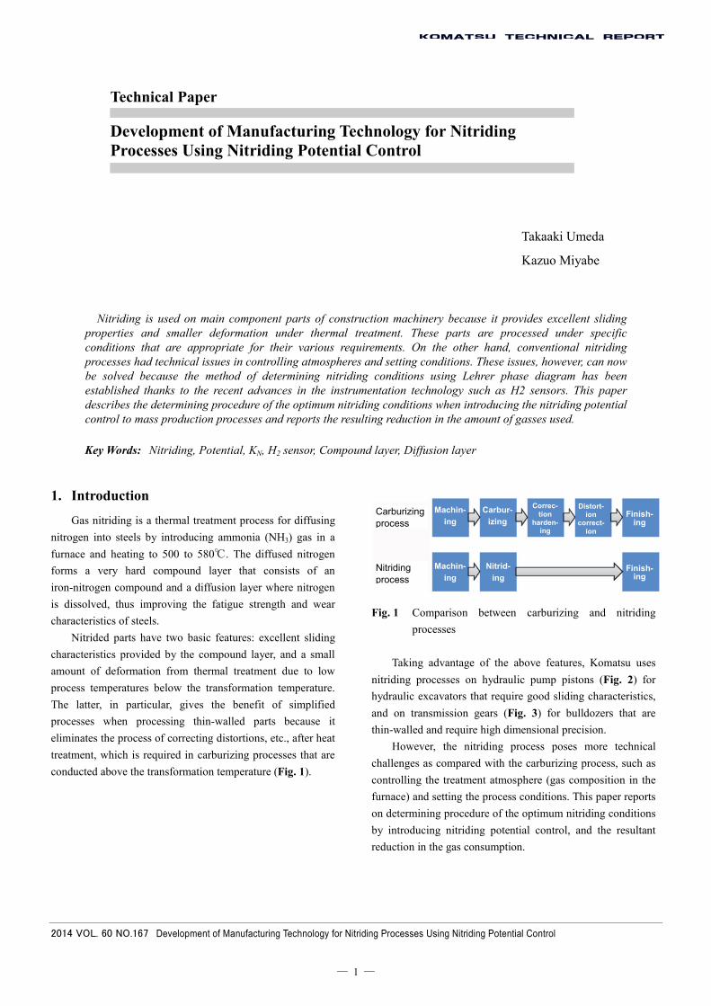
conducted above the transformation temperature (Fig. 1).
Fig. 1 Comparison between carburizing and nitriding
processes
Taking advantage of the above features, Komatsu uses
nitriding processes on hydraulic pump pistons (Fig. 2) for
hydraulic excavators that require good sliding characteristics,
and on transmission gears (Fig. 3) for bulldozers that are
thin-walled and require high dimensional precision.
However, the nitriding process poses more technical
challenges as compared with the carburizing process, such as
controlling the treatment atmosphere (gas composition in the
furnace) and setting the process conditions. This paper reports
on determining procedure of the optimum nitriding conditions
by introducing nitriding potential control, and the resultant
reduction in the gas consumption.
Carburizingprocess
Machin-ing
Carbur- izing
Correc- tion
harden- ing
Distort-ion
correct-ion
Finish-ing
Nitriding process
Nitrid-ing
Machin-ing
Finish-ing

2014 VOL. 60 NO.167 Development of Manufacturing Technology for Nitriding Processes Using Nitriding Potential Control
― 2 ―
Fig. 2 Hydraulic pump piston for hydraulic excavators
Fig. 3 Transmission gear for bulldozers
2. Phases Produced in the Nitriding Process
Fig. 4 shows a photo of the structure of a nitrided part,
and Fig. 5 shows a binary phase diagram1) of Fe-N. Nitriding
is conducted at temperatures lower than 592˚C, or the
eutectoid temperature of Fe-N. This process produces a 5 to
20m thick compound layer consisting of the and ’ phases,
and an approximately 0.5 mm thick diffusion layer.
The phase produced in the outermost surface of the
compound layer is composed of Fe2-3N and contains 7.7-11.1
mass% nitrogen. This phase, also called a porous layer, has a
structure of fine and brittle pores that are connected like a
chain. There are two different opinions as to its properties.
One says that this phase forms a conforming surface in the
initial stage of use, while the other insists that delamination
accelerates wear. Therefore, its thickness is controlled in an
atmosphere that is appropriately controlled according to the
properties required for the part. This phase is removed by
machining in some cases. The ’ phase, which is formed at the
inside of phase, is composed of Fe4N and contains 5.9
mass% nitrogen. Since this phase has a dense structure, it
exhibits good sliding characteristics.
At the temperature of 592˚C, up to 0.1 mass% nitrogen is
dissolved in the phase of the diffusion layer, causing solid
solution hardening, and also precipitation hardening occurs
due to the formation of fine nitride compounds by alloy
elements contained in the steel. The hardening depth is greater
than the compound layer thickness, and the depthwise
hardness is primarily provided by the diffusion layer.
The compound and diffusion layers generated in nitriding
vary in the formation state depending on the nitriding
conditions, which results in significant variations in the
hardness and sliding characteristics of parts. Therefore, it is
necessary to process parts under specific conditions that are
appropriate for the required properties.
Fig. 4 Structure of nitrided part
Fig. 5 Binary phase diagram of Fe-N
3. Atmosphere Control
In gas nitriding, NH3 is used as a nitrogen source to steels.
Two types of reaction occur in the furnace. The first is the
thermal decomposition of NH3, expressed by formula (1), and
the second is the generation of nitrogen by dissociation
caused by the catalytic reaction of iron, expressed by formula
(2).
NH3→1/2N2+3/2H2 ・・・(1)
NH3→[N]+3/2H2 ・・・(2)
At the process temperature, NH3 is thermally
decomposed as in formula (1), and the generated nitrogen
atoms quickly become nitrogen molecules, and therefore do
not diffuse in steels. On the other hand, the nascent nitrogen
generated by catalysis of steel, shown in formula (2), is
Tem
pera
ture
(˚C
)
Nitrogen concentration (mass%)
Compound layer
Diffusion layer

2014 VOL. 60 NO.167 Development of Manufacturing Technology for Nitriding Processes Using Nitriding Potential Control
― 3 ―
diffused into the steel2).
Since the above two reactions occur simultaneously in
the furnace, NH3 is constantly introduced in the furnace so
that the nitriding atmosphere containing NH3 is maintained to
supply nitrogen to the steel.
The atmosphere in the furnace needs to be maintained at
a required value to obtain stable nitriding quality. However,
since the atmosphere changes during the treatment depending
on the furnace temperature and the diffusion state of nitrogen
in the workpiece, the amount of introduced NH3 needs to be
constantly adjusted.
In the past, desociometers were used to measure and
adjust the amount of NH3 to be introduced since NH3 in the
atmosphere easily dissolves in water (Fig. 6). However, this
method allowed only intermittent measurement, and the
process could not be automated because the introducing
amount had to be adjusted manually.
In recent years, infrared absorption type NH3
concentration analyzers3) capable of automatic measurement
of NH3 concentration and heat conduction type H2 sensors4)
that allow automatic measurement of H2 concentration by
directly inserting the sensor in the furnace have been
developed. It is now possible to continuously measure the
atmosphere and automatically control the introducing amount
by combining these sensors with computers and mass flow
controllers (MFC) (Fig. 7).
Advances in these instrumentation technologies have
enabled highly accurate control of atmosphere that was not
possible before.
Fig. 6 Desociometer
Fig. 7 Control schematic
4. Setting the Conditions Using the Lehrer Phase Diagram
In the past, NH3 concentration has been used as an index
of furnace atmospheres. The ASM Metals Handbook5) shows
a two-stage nitriding process that changes temperature and
NH3 concentration during the process with the conditions of
500 to 525℃/NH3 70 to 85% in the first stage and 550 to
565℃/NH3 15 to 35% in the second stage. Temperature is
increased and NH3 concentration is decreased in the second
stage to promote nitrogen diffusion into the material and to
restrict the thickness of the phase. However, the correlation
between NH3 concentration and generated phases was not
clear.
Later, Lehrer studied the equilibrium of iron and NH3,
revealing the correlation between the nitriding potential KN
derived from NH3 concentration and the generated phases at
equilibrium using the Lehrer phase diagram6),7) (Fig. 8).
The nitriding potential KN defined by formula (3) is used
to replace NH3 concentration as an index of the nitriding
capability of atmospheres. = ・・・(3)
:Nitriding potential
:Partial pressure of ammonia
:Partial pressure of hydrogen
For example, applying formula (3) to the 500℃/NH370%
shown as the condition in the first stage of the two-stage
nitriding process produces the nitriding potential KN of 6.7,
which is expected to form in the outermost layer based on
the Lehrer phase diagram. If the amount of generation needs
to be restricted, we can expect that the desired phase can be
obtained by lowering the nitriding potential KN to close to
KN2 at the /’ boundary.
By using the Lehrer phase diagram, it is now possible to
examine in advance the conditions, i.e., the temperature and
KN (NH3 concentration), for obtaining generated phases as
desired. It has also become possible to set the optimum
conditions by determining the lowest KN for obtaining the
desired phase based on the Lehrer phase diagram.
Furnace concentration
Infrared NH3 analyzer
Regulator Signal

2014 VOL. 60 NO.167 Development of Manufacturing Technology for Nitriding Processes Using Nitriding Potential Control
― 4 ―
Fig. 8 Lehrer phase diagram
5. Forecasting Required Gas Flow Rate Due to Change in KN
We forecasted the required flow rate of NH3 gas due to
the change in KN8). The NH3 concentration in the furnace is
modeled in Fig. 9.
Fig. 9 NH3 concentration in the furnace
The change in NH3 concentration due to gas substitution
is expressed by formula (4). = ・・・(4)
Ci:Concentration of introduced NH3
C:Concentration of NH3 in furnace
V:Furnace volume
The change in NH3 concentration due the gas
decomposition reaction of formula (1) is expressed by
formula (5). = − =− ( ) ・・・(5)
k:Reaction speed constant
: (1-C)
By adding formulas (4) and (5), we obtained formula (6)
for determining the NH3 concentration in the furnace. = − ( ) ・・・(6)
The NH3 concentration, or the nitriding potential KN, can
be determined by calculating the reaction speed constant k,
specific to each furnace, in advance from a known NH3
concentration obtained for a certain flow rate and then
successively calculating formula (6) for each Δt.
Estimating the flow rate of NH3 when the nitriding
potential in the first stage of the two-stage nitriding would be
reduced from KN 6.7 to close to the /’ boundary, we
anticipated that the hourly flow rate could be reduced by 80%,
which indicated that the reduction of KN would be effective
for restricting the gas flow rate.
Fig. 10 Hourly change in gas flow rate
As described above, we are able to predict the condition
of the compound layer produced on the surface of a
workpiece in advance by introducing the potential control of
nitriding that combines atmosphere control using new
instrumentation technology and the condition setting method
using the Lehrer phase diagram. Based upon this, we
conducted quality examinations using a production furnace.
The aim was to determine the optimum nitriding conditions
required for achieving the target quality and to reduce gas
consumption.
6. Examination of Quality
We processed test pieces of a round bar shape with a 30
mm diameter using the nitriding potential control. The test
pieces are made of steel for nitriding based on SCM435H
added with nitride generating elements, and a pit type gas
nitriding furnace with an effective dimension of 1200 dia. x
1200 was used for the treatment. The process condition
consisted of changing the KN level in the first stage of the
two-stage nitriding described above between “small”,
“medium” and “large” in the phase region (Fig. 11).
NH
3 ga
s flo
w r
ate
(inde
x)
ε/γ’ boundary Nitriding potential KN
Temperature
Nitriding furnace
Volume: V
Concentration: C
,,

2014 VOL. 60 NO.167 Development of Manufacturing Technology for Nitriding Processes Using Nitriding Potential Control
― 5 ―
Fig. 11 Process pattern
This test resulted in a constant hardness in the 50 m
position regardless of the potential, as shown in Fig. 12, and
there was no significant difference in both the hardness
distribution in the diffusion layer in Fig. 13, and the nitrogen
concentration distribution in Fig. 14, between different KN
levels. The compound constituent in Fig. 15 and the structure
photos in Fig. 16 indicate that the ratio of the phase
decreases as the KN decreases, which is consistent with the
quality expected from the Lehrer phase diagram.
From the above observations, it was confirmed that the
hardness distribution in the diffusion layer does not change
even if the KN in the first stage of the two-stage nitriding
decreases in the phase region, allowing the KN to be
decreased in the range where the compound thickness satisfies
the specifications.
Fig. 12 Hardness at 50 m (N=10 in average)
Fig. 13 Hardness distribution in diffusion layer (N=10 in
average)
Fig. 14. Nitrogen concentration distribution
Fig. 15 Compound layer constitution (N=3 in average)
Com
poun
d la
yer
thic
knes
s (μ
m)
Nitriding potential KN
Small Medium Large
ε ra
tio (
%)
Nitr
ogen
con
cent
ratio
n(in
dex)
Nitr
ogen
con
cent
ratio
n(in
dex)
Depth (mm)
Depth (mm)
LargeKN
Small KN
Small KN
Large KN
Depth (mm)
Small
Har
dnes
s at
50 μ
m H
V
Medium Large
N=10 in average
Nitriding potential KN
Large KN
Medium KN
Small KN

2014 VOL. 60 NO.167 Development of Manufacturing Technology for Nitriding Processes Using Nitriding Potential Control
― 6 ―
Fig. 16 Structure photos
7. Considerations
We consider the reason why there was no change in the
hardness distribution in the diffusion layer of the test pieces.
The hardness in the diffusion layer is dependent on the
concentration of the nitrogen diffused in the layer, and the
diffusion speed of nitrogen is dependent on the concentration
gradient of active nitrogen if the material and temperature are
the same.
Fig. 17 shows a schematic of the phase generation and
the change in nitrogen concentration when nitriding takes
place in the region.
I. At the initial stage of the process, nitrogen
dissociated from ammonia dissolves and increases its
concentration in the phase.
II. The ’ phase is produced when the nitrogen
concentration in the phase reaches the saturation point at
the process temperature,
III. Similarly , the phase is produced when the ’ phase reaches the saturation point. The nitrogen concentration
on the steel surface becomes equilibrium with the potential
KN of the atmosphere.
When ’ compound is produced along the way of the
process, the phase is supplied with nitrogen through the ’ phase. Therefore, it is considered that the nitrogen diffusion in
the phase is dependent on the concentration difference
between the ’ and phases, and is not affected by the
potential KN of the atmosphere after ’ is generated.
Fig. 18 is a schematic of the nitrogen concentration when
the KN decreases, which shows that the reduction of the KN
affects the nitrogen concentration in the phase only without
causing changes in the concentration difference between the ’ and phases. This is considered to be the reason why there is
no difference in the nitrogen concentration distribution and a
similar hardness distribution is obtained in Fig. 14.
Fig. 17 Schematic of phase formation and nitrogen
concentration in nitriding process
Fig. 18 Schematic of nitrogen concentration when KN
reduces
8. Application to Mass Production Processes
An example of applying nitriding potential control to a
mass production process is shown below. We conducted the
optimization of the KN while maintaining the current hardness
distribution and phase formation in the nitriding process of
transmission gears.
As a result, the NH3 gas flow rate decreased during the
process, and we succeeded to reduce the gas consumption per
charge including the necessary displacement of in-furnace
atmosphere by 46% (Fig. 19).
Nitro
gen
conc
entra
tion
Depth
Concentration difference between α and γ’
Reduction in KN
Solution in α
Nitro
gen
conc
entra
tion
Generation of γ’
Generation of ε
Nitro
gen
conc
entra
tion
Nitro
gen
conc
entra
tion
Depth
Depth
Depth
Concentration difference between α and γ’
Concentration difference between α and γ’
Large KN
Small KN

2014 VOL. 60 NO.167 Development of Manufacturing Technology for Nitriding Processes Using Nitriding Potential Control
― 7 ―
Fig. 19 Comparison of gas consumption
9. Conclusion
We introduced nitriding potential control that combines
atmosphere control techniques and a condition setting method
using the Lehrer phase diagram in the nitriding process for
manufacturing transmission gears for construction equipment.
This has allowed us to predict the compound layer produced
on the workpiece surface and to determine the optimum
nitriding conditions for achieving the target quality. As a
result, we have succeeded in controlling the compound layer
while maintaining the current hardness distribution, thus
reducing NH3 gas consumption.
References
1) Dieter Liedtke, “Nitriding and Nitrocarburizing on Iron
Materials” (2011).
2) Shoichi Kiyooka, “Gas Nitriding” in Heat Treatment, Vol.
10, Issue 1 (1970).
3) Masahiko Fujiwara, “Continuously Measuring Device
for Ammonia Concentration in Nitriding Processes”, in
Heat Treatment, Vol. 45, Issue 5 (2005).
4) Kazuki Kawada, “Gas Nitrocarburizing Furnace with a
Nitriding Potential Control System”, in Heat Treatment,
Vol. 49, Issue 2 (2009).
5) METALS HANDBOOK, Vol. 2 “Heat Treating,
Cleaning and Finishing”, 8th Edition.
6) Lehrer, E, “Z. Elektrochemie” 36 (1930)
7) Spies, H.-J “Harterei-Techn. Mitt” 58 (2003)
8) Hyojiro Kurabe, “Behaviors of Ammonia Gas in
Carbonitriding Processes”, in Iron and Steel, Issue 9
(1973)
Introduction of the writers
Takaaki Umeda
Joined Komatsu Ltd. in 2009.
Currently a member of the Production
Engineering Department, Production
Division, Awazu Plant.
Kazuo Miyabe
Joined Komatsu Ltd. in 1994.
Currently General Manager of Components
and Heat Treatment Group, Manufacturing
Engineering Development Center,
Production Division.
[A few words from writers]
Our effort has contributed to the cost reduction of main
components. Based on this technology, we would like to further
develop heat treatment technologies including component layer
control for quality improvement and composite heat treatment
that combines nitriding and other heat treatment processes for
better functionality, thus contributing to the competitiveness of
Komatsu, which manufactures components in-house.
Gas c
onsu
mptio
n (ind
ex)
Current KN controlled