free ebooks download
DESCRIPTION
here you will get ebooks as per university syllabusTRANSCRIPT
Free Ebooks Download Mba Ebooks
By dholeMba ebooksFree ebooks download
http://ebooks.edhole.com

Department of Electrical and Computer Engineering
EE20A - Electromechanical Energy EE20A - Electromechanical Energy ConversionConversion
DC MachineDC Machine

Construction of DC Machines Construction of DC Machines
Commutator

Features of DC Machine Features of DC Machine
Field Winding

DC Machines- DC Machines- Direction of Power Flow and Losses Direction of Power Flow and Losses

DC Machines- DC Machines- Direction of Power Flow and Losses Direction of Power Flow and Losses

DC Machines AnalysisDC Machines AnalysisSymbols that will be used.
= flux per pole p = no. of poles z = total number of active conductors on the armature a = no. of parallel paths in the armature winding
Aside: Lap Winding -> a = p Wave Winding -> a = 2
n = speed of rotation of the armature in rpmwm = speed in radians per second

DC Machines ConnectionsDC Machines Connections
E
-
+Field
F F
Armature
b) Separately Excited
E
RaIf +
--
+
VT
a)
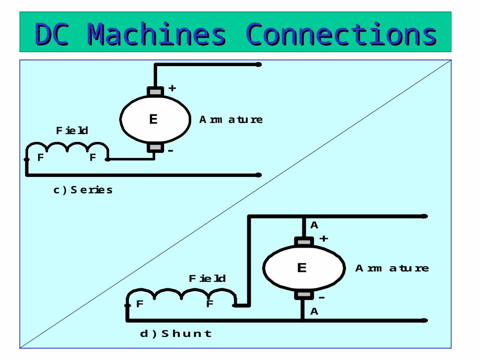
DC Machines ConnectionsDC Machines Connections
E
-
+
Field
F F
Armature
c) Series
E
-
+
Field
F F
Armature
d) Shunt
A
A

DC Machines ConnectionsDC Machines Connections
E
-
+
Field FF
Armaturee) Cummulative Compound
A
A
S S
E
-
+
Field FF
Armatured) Differential Compound
A
A
S S

DC Machines ConnectionsDC Machines Connections
E
-
+
Field FF
Armature
g) Short Shunt
A
A
S S
E
-
+
Field FF
Armature
f) Long Shunt
A
A
S S

EMF EquationEMF Equation
When the rotor rotates in the field a voltage is developed in the armature.
- the flux cut by one conductor in one rotation = p
-
-
- therefore in n rotations, the flux cut by one conductor = np

EMF EquationEMF Equation
EMF induced in the armature windings

TORQUE EQUATIONTORQUE EQUATION
EaIa=Tem - In the DC machine losses areexpressed as rotational losses due to friction and windage (F&W).
- The torque equation can then be rewritten as:-
SHAFT OUTPUT TORQUE = (Te - TF&W)

DC GeneratorDC Generator
LIfIaI
fR
LVf
I
aRaIaELV
ap
60Nz
aE
E
Ra I f+
--
+
VTR f
LOAD
I a
Note: VT = VL
i.e. Terminal Voltage is the Load Voltage

OPEN CIRCUIT CHARACTERISTICSOPEN CIRCUIT CHARACTERISTICS
The Open Circuit characteristic is a graph relating Open-Circuit Armature voltage of a D.C. Generator versus its field current when the machine is driven at it’s rated speed
DCSource
A
FL
F
L
ZZ
Z
Field Current
Fie
ld R
eg
ula
tor
R f Ea
R a
AA
A
V
OPENCIRCUIT
Diagram showing motor connections for the open circuit test, separately excited
The D.C. Generator field is excited by a separate D.C. source and the current is varied using a generator Field Regulator (a potential divider).

OPEN CIRCUIT CHARACTERISTICSOPEN CIRCUIT CHARACTERISTICS
R a
Z
R f
ZZ
Ea
AA
A
AField Current
V VT
R ext970 ohm s
Diagram showing the D.C. Generator as a self-excited shunt machine
Rext is set to its maximum value. The D.C. Generator is driven at
rated its speed. Rext is decrease to a lower value so that the
machine self-excites ( i.e.. Develop an e.m.f).

EXTERNAL CHARACTERISTIC OF SHUNT GENERATOREXTERNAL CHARACTERISTIC OF SHUNT GENERATOR
This is a graph relating terminal voltage and the load current of a D.C. Generator when driven at its rated speed with the field current maintained at its normal no-load value.
R a
Z
R f
ZZ
Ea
AA
A
AField Current
VR ext
970 ohm s
A
LOAD
Load Current
T erm inalVo ltage
Diagram showing connections for load test.

Summary
Losses Rotational andf
R 2
fI
-- Windings(Armature)-- Windings(Field )
aR 2
aI Losses
aEn
pza60aRaI -V
n Speed
a60pzn
aE
aRaI -VaE
Note: For motor
(Windage and Friction)
