fracture in phenolic impregnated carbon ablator · 42nd aiaa thermophysics conference, honolulu,...
TRANSCRIPT

42nd AIAA Thermophysics Conference, Honolulu, Hawaii, June 2011.
American Institute of Aeronautics and Astronautics
1
Fracture in Phenolic Impregnated Carbon Ablator
Parul Agrawal* and Jose F. Chavez-Garcia
ERC Corporation, NASA Ames Moffett Field, CA-94035.
The thermal protection materials used for spacecraft heat shields are subjected to various thermal-mechanical loads during an atmospheric entry which can threaten the structural integrity of the system. Thispaper describes the development of a novel technique to understand the failure mechanisms inside thermalprotection materials. The focus of research is on the class of materials known as Phenolic ImpregnatedCarbon Ablators (PICA). PICA has successfully flown on the Stardust spacecraft and is the TPS materialchosen for the Mars Science Laboratory (MSL) and SpaceX Dragon spacecraft. Although PICA has goodthermal properties, structurally, it is a weak material. In order to thoroughly understand failure in PICA,fracture tests were performed on FiberForm®* (precursor of PICA), virgin and charred PICA materials.Several samples of these materials were tested to investigate failure mechanisms at a microstructural scale.Stress-strain data were obtained simultaneously to estimate the fracture toughness. It was found that cracksinitiated and grew in the FiberForm when a critical stress limit was reached such that the carbon fibersseparated from the binder. However, both for virgin and charred PICA, crack initiation and growth occurredin the matrix (phenolic) phase. Both virgin and charred PICA showed greater strength values compared toFiberForm coupons, confirming that the presence of the porous matrix helps in absorbing the fractureenergy.
I. Introduction
Fracture in any system is a catastrophic event that system designers try to prevent. In spacecraft heat shields, it isof paramount importance as safety of the crew members and success of the mission is at stake, and it affects theplanning for future missions. The Columbia disaster occurred due to mechanical damage to the thermal protectionsystem (TPS) that could not survive the heating during re-entry1. However, the study and analysis work involvedwith thermal protection materials is very complex. Many factors contributing to this complexity are: porosity ofthermal protection materials, temperature dependent mechanical and physical properties, and a combination ofthermal and mechanical loads at various points in the trajectory. While arc-jet and other thermal-mechanical testsprovide some understanding regarding the survivability of TPS materials2,3, an in-depth systematic studies of fracturetoughness and failure mechanisms are required to optimize materials and predict the failure in TPS when subjectedto a combination of thermal-mechanical loads. Some researchers in past, have investigated the fracturecharacteristics of ceramic thermal protection tiles, used in Space Shuttle4,5, however, to the authors knowledge therehas not been extensive research performed to study fracture toughness and failure mechanisms at a microstructurescale in ablating TPS materials. The research discussed in this paper is one of the first attempts to investigate failuremechanisms in ablators at a micro-structural scale and provide an understanding that may lead to the development of
* Senior Research Scientist, NASA Ames Research Center, Thermal Protection Materials Branch, MS 234-1, MoffettField, CA 94035, (650)-604-3764, AIAA Sr. Member.
Research Scientist, NASA Ames Research Center, Thermal Protection Materials and Systems Branch, MS 234-1,Moffett Field, CA 94035.
* Registered trademark of Fiber Materials Incorporated.
https://ntrs.nasa.gov/search.jsp?R=20110015019 2018-08-04T17:43:01+00:00Z

42nd AIAA Thermophysics Conference, Honolulu, Hawaii, June 2011.
American Institute of Aeronautics and Astronautics
2
structurally stronger materials. The present work focuses on investigating the failure mechanisms in PhenolicImpregnated Carbon Ablator (PICA).
PICA is a logical choice for this research because it was the material used on the Stardust probe6 and will be usedin the heat shield for the Mars Science Lab (MSL)7 mission and on the SpaceX Dragon spacecraft8. PICA wasdeveloped by scientists at NASA Ames in 19969. Although PICA has very good thermal properties, structurally it isa weak material, posing a challenge for the system designers to use it in the presence of mechanical loads and severestresses. Several development efforts are underway to improve the structural properties of PICA withoutcompromising the thermal properties or significantly increasing the density. The researchers at NASA Ames andFiber Materials Incorporated (FMI) have been changing process parameters to alter the microstructure to improvemechanical properties10,11,12. In order to optimize the microstructure it is important to understand mechanisms ofcrack initiation and propagation at a microstructure scale. In the present research the mechanical tests wereperformed on FiberForm (precursor of PICA), virgin and charred PICA and crack propagation was investigated at amicrostructure scale in each case. These tests also provided the data for estimation of fracture toughness, which canbe later used for modeling of fracture as well as development of micromechanical failure models. The next sectiondescribes the microstructure of FiberForm, virgin, and charred PICA. Section III and IV discuss the instrumentationand specimen design. Section V describes the test data and results. Summary and conclusions are provided in sectionVI.
II.Microstructure
A. Fiberform
FiberForm is a low density very porous carbon fiber insulation material designed for high temperatures applications.It is processed at Fiber Materials Incorporated (FMI) and is the precursor substrate for processing PICA.Micrographs of FiberForm at different magnifications are shown in Figure 1. It consists of a group of carbon fibersbonded to each other by means of an organic binder that is carbonized at very high temperature. After carbonization,all the organics evaporate and only a thin carbonaceous phase remains as the binder that holds the fibers together.The binder concentration varies and, in some places, there are smaller concentrations while in other places there is afairly large group of fibers bound together. Some cross-linking that joins the fibers together and makes it a rigidpreform also takes place during the processing. Each individual strand of carbon fiber consists of 5-6 individualfibers of diameter 5-6 um that are joined together as shown in the higher magnification micrograph of Figure 1. Thecarbon fibers in FiberForm are oriented preferentially in one plane, as a result of the manufacturing process, makingit a transverse isotropic material with different material properties in through-the-thickness (TTT) and in-plane (IP)directions. The IP strength and stiffness of FiberForm is significantly higher compared to the TTT direction. Thismaterial was tested first in the in-plane direction to obtain tensile strength and understand the failure mechanism.
B. Virgin PICA
As the name suggests, PICA is made by impregnation of phenolic resin within the FiberForm, followed by a curecycle at an elevated temperature. It could be viewed as a two phase material consisting of a network of carbon fibersand a very porous phenolic matrix dispersed on and in-between the fibers as shown in Figure 2. This highly porousstructure makes it a low density ablator. Due to the preferential orientation of carbon fibers in the FiberForm, PICAalso displays the transverse isotropic behavior with significantly higher strength and stiffness in the in-plane directioncompared to TTT direction.
C. Charred PICA
Ablative TPS materials are subjected to very high heat flux during atmospheric re-entry causing them to pyrolyzeand char. In order to understand the effects of phase changes due to pyrolysis, two types of charred PICA materials,furnace charred and arc-jet charred PICA were studied. Furnace charred PICA samples were created by heating thespecimens in a tube furnace to 13000C in inert environment. All the specimens were heated until they were uniformlycharred. While all the organic material from the phenolic resin was evaporated, a thin carbonaceous matrix phase

42nd AIAA Thermophysics Conference, Honolulu, Hawaii, June 2011.
American Institute of Aeronautics and Astronautics
3
was still present between the carbon fibers. The arc-jet charred PICA samples were prepared by cutting the uppercharred PICA layer of post arc-jet test samples. Micrographs of both arc-jet and furnace charred PICA materials areshown in Figure 3a and 3b, respectively. Both materials show the presence of porous and thin carbonaceous matrixphase dispersed between the carbon fibers. However, in the arc-jet charred PICA the matrix on the top char layers issparser compared to the furnace charred PICA. This is caused by the oxidation in arc-jet environment. Thisphenomenon was also observed in the PICA char on the Stardust reentry probe13.
Figure 1: Micrographs of FiberForm at different magnifications.
Figure 2: Micrographs of PICA at different magnifications.
Figure 3: Micrographs of a) arc-jet char and b) furnace charred PICA.

42nd AIAA Thermophysics Conference, Honolulu, Hawaii, June 2011.
American Institute of Aeronautics and Astronautics
4
III. Experiment Design and Equipment
The experiments were performed inside a Philips XL-30 electron microscope unit from FEI (Fig. 4). A miniaturecustom designed mechanical stage was mounted inside the microscope chamber as shown in Figure 5. A dataacquisition system was integrated to the stage to acquire stress-strain data during the tests. The mechanical sub-stagewas driven by a small motor and could exert a tensile or compressive load of up to 5 kN on a suitable test specimen.A strain transducer was mounted on the stage that provided the displacement measurements. The stage canaccommodate a range of samples with dimensions varying from 20.0 mm to 60.0 mm in length, 5.0 mm to 15.0 mmin width and 0.01 mm to 6.0 mm in thickness. These dimensions are ideal to obtain preliminary mechanicalproperties data for an experimental material.
Figure 4: Experiment set-up for in-situ SEM fracture experiments
Figure 5: Close up of the mechanical sub-stage
IV. Specimen Design
Small samples of dimension 5.7 cm x 1.0 cm x 0.38 cm were cut from a single PICA billet and FiberForm block.Sample dimensions and drawings are shown in Figure 6. To initiate fracture in a controlled manner and focus theelectron beam to obtain high magnification micrographs, fine notches were cut into the samples at the midline, usinga micro scriber tool. One of the notched charred PICA samples is shown in Figure 7. Specimens were fabricated with

42nd AIAA Thermophysics Conference, Honolulu, Hawaii, June 2011.
American Institute of Aeronautics and Astronautics
5
and without notches for each FiberForm, virgin and charred PICA materials to compare the stress-strain behaviorand in-plane tensile strength. The notches were nominally 1.27mm to 2.54 mm in depth. The notch tip radius in mostspecimens was approximately 100 µm. These dimensions were sufficient to initiate crack at the notch tip and viewthe failure mechanisms in FiberForm and PICA. Thin aluminum tabs were glued to the ends of all the coupons withhelp of transfer coated RTV-560 (room temperature vulcanized) adhesive. This was required to avoid any localdamage, slipping and premature failure of specimens near the grips.
Figure 6: Specimen geometry (dimensions in mm).
Figure 7: Micrograph of a charred PICA coupon with a notch at different magnifications.
V.Test Results and Analysis
All the materials were tested at room temperature in the in-plane tension configuration as it is the strongerdirection and it is easier to obtain the data. The samples were pulled inside the SEM chamber under high vacuum of3.0e-04 mBar. To obtain quasi-static conditions, the samples were pulled at a rate of 0.1 mm/sec. The secondaryelectron mode detector was used to obtain high quality micrographs. For notched samples, the electron beam wasfocused at the notch tip prior to tests. Several micrographs were obtained near the notch tip prior to test in order tocreate a complete map near the notch at magnifications ranging from 25X-100X. A video camera was connected tothe microscope to capture the fracture in real time (30 frames/sec). When a specimen was fractured, micrographs atvarious magnifications were obtained to observe the crack initiation and growth. Stress strain data from the load celland strain transducer were obtained at the same time using the data acquisition system. Some of the coupons weretested without notches to create a uniform uniaxial tension test configuration. While the primary objective of in-situSEM testing was to observe the failure mechanisms inside the TPS material, the stress-strain data obtained duringthese tests helped in understanding the influence of material flaws on the stress-strain relationship. For somematerials, like charred PICA, there are no tension test data available. The tension tests described here helped to
Direction ofloading

42nd AIAA Thermophysics Conference, Honolulu, Hawaii, June 2011.
American Institute of Aeronautics and Astronautics
6
obtain the in-plane tensile strength and toughness of charred PICA materials. The in-plane strength data forFiberForm, virgin, and charred PICA obtained during the tests, were compared with the configuration managed(CM) Crew Exploration Vehicle (CEV) TPS Advanced Development Project (ADP) material properties databasevalues14 to validate the tests and establish accuracy.
A. FiberForm Fracture Tests
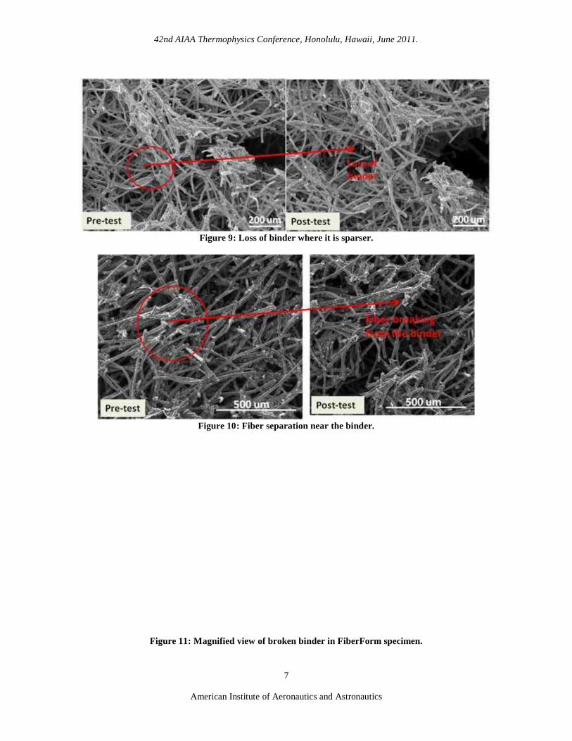
Fracture tests were performed on both notched and un-notched FiberForm samples. The dimensions werekept constant across the samples to obtain consistent results. A 450N load cell was used for these tests because itprovides more accurate information for smaller magnitude loads. For all the specimens with notches, cracks initiatedand grew near the tip of notch. All the specimens fractured in a brittle manner as soon as they reached a criticaltensile stress. The crack initiation was captured on video. Figure 8 shows the crack initiation near the notch tip in oneof the specimens. By examining the videos and comparing pre-test versus post test micrographs, it can be seen thatwhen the specimens reached a critical stress magnitude, the carbon fibers were pulled away from the binder where itwas in smaller concentration. Figure 9 shows the loss of binder material and Figure 10 shows micrograph of fiberseparation near the binder phase. Figure 11 also shows a magnified view of broken carbonaceous binder. Fiberbreaking was not observed in any of the specimens. The tensile strength values and stress-strain data forrepresentative un-notched and notched FiberForm coupons are shown in Figure 12. All the specimens fractured inthe range of 400-600 KPa stress magnitude and presence of notches did not make a significant difference in tensilestrength. This phenomenon is very different from traditional dense material and it will be important to take this intoaccount when modeling fracture behavior of porous material. The stress-strain curves obtained for these samples alsosuggested nonlinear stress-strain behavior from the very beginning. For most specimens, the strain-to-failure wasbetween 0.6%-1.0%. The strength data is comparable to the data obtained on FiberForm in the CM database for theOrion program14.
Figure 8: Crack initiation in FiberForm.
42nd AIAA Thermophysics Conference, Honolulu, Hawaii, June 2011.
American Institute of Aeronautics and Astronautics
7
Figure 9: Loss of binder where it is sparser.
Figure 10: Fiber separation near the binder.
Figure 11: Magnified view of broken binder in FiberForm specimen.

42nd AIAA Thermophysics Conference, Honolulu, Hawaii, June 2011.
American Institute of Aeronautics and Astronautics
8
Figure12: In-plane tensile strength and stress-strain data for FiberForm specimens.
B. Virgin PICA Fracture Tests
Fracture tests were performed on both notched and un-notched virgin PICA samples. The dimensions werekept constants across the samples to obtain consistent results. Specimens were fabricated with two different notchsizes, 1.27 mm and 2.54 mm, to investigate the effects of flaw size on strength and mechanical behavior. Similar toFiberForm, PICA specimens also fractured in a brittle fashion. Once specimens were at the critical stress magnitude,initiation and progress of cracks was rapid. Videos and micrographs capturing the crack initiation and crack pathswere obtained during the testing of multiple notched specimens. For notched PICA specimens, the cracks initiated inthe porous matrix phase near the notch tip, as shown in Figure 13. It progressed further in the phenolic matrix phase.The crack paths were governed by the presence of voids in the phenolic matrix phase. At various locations, crackbridging by carbon fibers as well as carbon fiber pull-out was observed. One such example is shown in one of posttest micrograph in Figure 14. Stress-strain data were obtained for all the specimens. The tensile strength values forvarious notched and un-notched samples, as well as representative stress-strain plot for un-notched and 2.54 mmnotched PICA samples, are shown in Figure 12. The presence of a phenolic matrix phase made a significantdifference in energy absorption in PICA. The critical stress of crack initiation and growth exceeded 1000 kPa, forsamples without notches and the ones with smaller (1.27 mm) notches. This magnitude is about twice the magnitudecompared to tensile strength in FiberForm samples. However, the samples with longer (2.54 mm) notches failed atlower values averaging 700 KPa. This shows that, unlike FiberForm, the presence of longer notches did reduce thetensile strength in virgin PICA. This is again an important aspect to consider when attempting to model porousmaterials and providing the critical stress values in the presence of flaws.
The specimens showed nonlinear stress-strain relation early on starting at 0.3% strain. The strain-to-failurefor these samples was in the range of 1.0% - 1.2% and tensile strength was in the range of 0.8 to 1.2 MPa, similar tothe CM database values, obtained during the in-plane tension test for Orion project 13.

42nd AIAA Thermophysics Conference, Honolulu, Hawaii, June 2011.
American Institute of Aeronautics and Astronautics
9
Figure 13: Crack initiation in virgin PICA Specimen.
Figure 14: Matrix cracking and fiber bridging in virgin PICA
Figure 15: In-plane tensile strength and stress-strain data for virgin PICA specimens.

42nd AIAA Thermophysics Conference, Honolulu, Hawaii, June 2011.
American Institute of Aeronautics and Astronautics
10
C. Charred PICA Tests
The charred PICA samples were prepared by two methods: charring the virgin material inside an inertfurnace, and sectioning pieces off of the charred portion of arc-jet tested PICA articles. Several furnace charredPICA specimens with ~2.54 mm notch size were tested inside the electron microscope. The crack initiation andgrowth was rapid once the critical stress was achieved, showing very similar behavior as virgin PICA samples.Videos and micrographs were obtained for the notched specimens. The crack initiated in the porous matrix phase andthe crack path followed the porous matrix. Carbon particle shedding in the porous matrix was also observed in somevideos. Fiber pull-out and bridging phenomenon, similar to virgin PICA samples, were observed at some locations asshown in Figure16. Figure 17 shows the evidence of matrix cracking. Most specimens failed between 600 kPa - 900kPa. The charred PICA samples made from arc-jet articles showed similar behavior and tensile strength as thefurnace char. Again, based on test data from most of the samples, the introduction of a notch did not make significantdifference in maximum tensile stress at which failure occurred. The stress-strain data and tensile strength forrepresentative samples are shown in Figure 18. The maximum tensile stress achieved for these specimens wasslightly higher than FiberForm samples but lower than virgin PICA. This suggests that fracture toughness of PICAablator is driven by the extent of energy that can be absorbed by the porous matrix phase. The charred PICAspecimens showed a similar non-linear stress-strain relation as FiberForm and virgin PICA samples. However, thestrain-to-failure in charred PICA samples was lower than virgin PICA. To the best of our knowledge, to date noother tensile testing of charred PICA material has been conducted. This was the first test series where stress-strainplots and tensile strength data for the in-plane tension loading configuration were obtained.
Figure 16: Crack initiation and growth in charred PICA coupons.
Figure 17: Matrix cracking in charred PICA samples.

42nd AIAA Thermophysics Conference, Honolulu, Hawaii, June 2011.
American Institute of Aeronautics and Astronautics
11
Figure 18: In-plane tensile strength and stress strain data for charred PICA specimens.
VI. Conclusions
Successful fracture testing of FiberForm, virgin PICA and charred PICA inside an electron microscope wasperformed. This research proved that investigation of failure mechanisms for TPS materials can be successfullyconducted at a microstructure scale. The tests provided valuable insights into failure mechanism of FiberForm andPICA materials. For notched samples, the crack initiated and grew at the notch tip and failure mechanisms in each ofthe materials was investigated at a microstructural scale by capturing videos of failure events and high magnificationmicrographs. FiberForm specimens fractured due to fiber pull-out from the carbonaceous binder wherever it waspresent in lower concentration. Occasional cracking of binder was also observed where it was sparse. In virgin andcharred PICA, the fracture was governed by the cracking of the matrix phase. In PICA, the phenolic matrix phaseplays an important role in absorbing the energy, and the fracture toughness of the material is significantly influencedby the toughness of the porous phenolic matrix. The stress-strain data were obtained simultaneously for each test.The data suggests that, for small flaws, the tensile strength is not affected, and the stress distribution inside thesample is governed by the material porosity. However, for larger flaws the critical failure stress values start todecrease. The in-plane tensile strength magnitude for FiberForm and virgin PICA was comparable to the valuesobtained during the CEV TPS ADP. The data suggests that this method can be very useful for obtaining reasonableestimates of the mechanical properties of charred ablators, including experimental TPS materials at TRL 1-2 stagewhere fabrication of large samples may not be possible. This research can also provide very valuable information forcomputational modeling of the fracture of porous materials and micromechanical modeling of TPS materials.
VII. Acknowledgments
The authors would like to acknowledge the support of the Exploration Technology Development andDemonstration (ETDD) Program, managed at NASA-Glenn Research Center. The work documented herein was
oject, which ismanaged at NASA Langley Research Center and supported by NASA Ames Research Center, NASA Johnson SpaceCenter, and the Jet Propulsion Laboratory. The authors gratefully acknowledge the support of element lead RobinBeck for the Entry, Descent and Landing (EDL) TPS program, Dr. Sylvia Johnson and Tom Squire for providingadditional funds for this research. We also acknowledge support of Peter Fullam for design and fabrication of sub-stages and support of summer interns Sammy Sabar and John Pham. Finally, we acknowledge the NASA STRADcontracts # NNA10DE12C to ERC to make this work possible.
VIII. References1 Columbia Crew Survival Investigation Report, NASA SP-2008-565, 2008.2 Driver, D. M., Arc Jet Testing in a Shear Environment for Mars Science Laboratory Thermal Protection System,
AIAA paper 2009-4230, 41st AIAA Thermophysics Conference, San Antonio, TX, June 2009.

42nd AIAA Thermophysics Conference, Honolulu, Hawaii, June 2011.
American Institute of Aeronautics and Astronautics
12
3 Agrawal P., Empey D.M., Squire T.H., "Thermal-Structural Analysis of PICA Tiles for Solar Tower Test," AIAA paper2009-3755, 41st AIAA Thermophysics Conference, San Antonio, TX, June 2009.
4 Green, D. J. and Lange, F. (1982), Journal of the AmericanCeramic Society, Vol. 65, No. 3, 1982, pp.138 140.
5 Komine A. and Kobayashi A. S., Interfacial-fracture of space shuttle thermal protection system, ExperimentalMechanics, Vol. 22, No. 12, 1982, pp. 454-461.
6 Journal of Spacecraft and Rockets, Vol. 36,No. 3, 1999, pp. 470-474.
7 Journal of Spacecraftand Rockets, Vol. 43, No. 2, 2006, pp. 257.
8 SpaceX Manufactured Heat Shield Material Passes High Temperature Tests Simulating Reentry Heating Conditions ofDragon Spacecraft SpaceX press release, URL http://www.spacex.com/press.php?page=20090223, Hawthorne, CA, February23, 2009.
9 Tran, H., Johnson, C, Rasky, D., Hui, F., Chen, Y.--1911, June 1996.
10 Fan W.,et Strengthening PICA with Functionalized Carbon Nanotubes, NASA TM-2010-216388, 2010.11 Fan W., Thornton J. and Stackpoole Chemistry and Material Properties of a New Class of Lightweight Ablators,
35th Annual Conference on Composites, Materials, and Structures, January 24-27, 2010 Cocoa Beach / Cape Canaveral, Florida.12 Low-Temperature Preform Processing, FMI technical disclosure, case #, ARC 16638-1.13 -flight evaluation of Stardust sample return capsule forebody
heatshield material, AIAA-2008-1202, 46th AIAA Aerospace Sciences Meeting and Exhibit, January 2008.14 Thermal and Mechanical Property Testing Orion Heat Shield Candidates, 34th
Annual Conference on Composites, Materials, and Structures, Cocoa Beach/Cape Canaveral, Florida, January 25-28, 2010.