fourier representations of switching functions freiberg · switching theory and digital signal...
TRANSCRIPT
Fourier Representations of
Switching Functions for Circuit Design
Radomir S. Stanković, Jaakko T. Astola
Tampere International Center for Signal ProcessingTampere University of Technology
FIN-33101 Tampere, Finland
Dept. of Computer Science, Faculty of Electronics18 000 Niš, Serbia

Outline
Motivations
Spectral Methods for Logic Design
- Why compact representations?
Fourier transforms on groups
Complexity of Fourier representations

Switching Theory and Digital Signal Processing
Switching theory mathematic foundations for Logic design TransmissionStorageProcessingof information encoded in digital (binary) signals
Methods in signal processing to solve problems in
DesignOptimizationVerification and testing of switching circuits and systems
Switching TheoryLogic Design
DSP

Goal of the Paper
Applications of group-theoretic methods in DSP to
Derivation of compact representations for switching functions
Design of logic circuits with regular structure
Logic circuit design from spectral representationsFourier series expression with varyed domain groupsEstimation of complexity

Transmission of Information
Discrete Signals and Digital Systems
Digital System
Logic Network
C.E. Shannon

Boolean Algebra
J. Boole
Design of digital systems from skills and art to science and engineering
Boole
Mathematical Analysis of Logic18471854

Why Compact Representations?
System-on-ChipNetwork-on-Chip
Design objective
Use fewer chips
Requirements in practice
Do more on a chipEliminating redundant gates
Reduces power dissipationFries up the chip area
Simplifies testing, etc.

Spectral Representations
Compact encoding of information Natural phenomena modelled by spectral methods
Implications
Different algebraic structuresMany, for instance
Group theory Spectral techniques
Hurst, S.L., Logical Processing of Digital Signals, Crane Russak and Edward Arnold, London and Basel, 1978.
Komamiya, Y., Information Theory,Application of Logical Mathematics to Information Theory,Application of Theory of Group to Logical Mathematics, 1953.

Aiken and his Comments
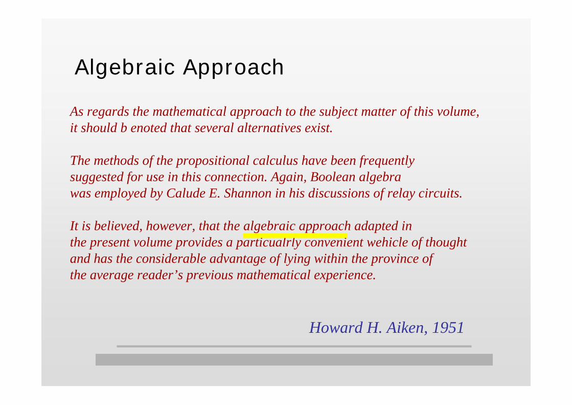
As regards the mathematical approach to the subject matter of this volume,it should b enoted that several alternatives exist.
The methods of the propositional calculus have been frequently suggested for use in this connection. Again, Boolean algebra was employed by Calude E. Shannon in his discussions of relay circuits.
It is believed, however, that the algebraic approach adapted in the present volume provides a particualrly convenient wehicle of thought and has the considerable advantage of lying within the province of the average reader’s previous mathematical experience.
Howard H. Aiken, 1951
Algebraic Approach
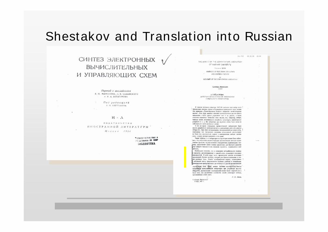
Shestakov and Translation into Russian

Switching Theory and DSP
Different interpretation of existing methods forbetter understanding and improved exploiting in practice
A unified approach to various results, their extensions, and generalizations
Derivation of completely new resutls for switching functions

Spectral Methods
Classical approaches
Change of basis functions Preserving some but not all useful properties
Mostly FFT-like algorithms Reduced number of non-zero coefficients
Fixed domain group, selected transforms
Disadvantage - missing of some properties
Group-theoretic approachFixed transform (Fourier), selected domain groups

Basic Characteristics of FutureComputing Technologies Regularity
Programmability and re-programmability
Delay constrains
Deep sub-micron effects
Logic span
Reusability
Brayton, R.K., "The future of logic synthesis and verfication", inHassoun, S., Sasao, T., (eds.), Logic Synthesis and Verication, Kluwer Academic Publishers, Boston, MA, USA, 2002, 403-434.

Some Available FPGA
IOB
IOB
IOB
IOB
IOB
IOB
IOB
IOB
IOB
IOB
IOB
IOB
IOB
IOB
IOB
IOB
IOB
IOB
IOB
IOB
IOB
IOB
IOB
IOB
IOB
IOB
IOB
IOB
IOB
IOB
IOB
IOB
CLB CLB CLB CLB
CLB CLB CLB CLB
CLB CLB CLB CLB
CLB CLB CLB CLB
B-SCAN
Routing Channel
OSC
RDBKSTART-UP
CLB - functional elements to implement logicIOB - interface between the package pins and
internal signal linesRouting Channels - pats to interconnect the inputs
and outputs of CLB and IOBsRDBK - read back the content of the configuration memoryand the level of certain internal nodes
START-UP - start-up bytes of data to provide four clocksfor the start-up sequence at the end of configuration
Spartan by Xilinix
Q
G-LUT
LogicFunctionofG1-G4
G4
G3
G2
G1
SR
H1
DIN
F4
F3
F2
F1
F-LUT
LogicFunctionofF1-F4
K
EC
H-LUT
LogicFunctionofF,G,H1
Multiplexer controlled byconfiguration program
SRD Q YQ
CK
EC
Y
SRD
CK
EC
XQ
X

Stratix by Altera
FPGA with DSP Block
22 DSP blocks with up to 172 9-bit × 9-bit embedded multipliers
IOE
IOE
IOE
IOE
IOE
IOE
IOE
IOE
IOE
IOE
IOE
IOE
IOE
IOE
IOE
IOE
IOE
IOE IOE IOEIOE
LAB LAB LABLAB
LAB LAB LABLAB
LAB LAB LABLAB
LAB LAB LABLAB
LAB LAB LABLAB
LAB LAB LABLAB
LAB LAB LABLAB
LAB LAB LABLAB
LAB LAB LABLAB
LAB LAB LABLAB
LAB LAB LABLAB
LAB LAB LABLAB
LAB LAB LABLAB
LAB LAB LABLAB
LAB LAB LABLAB
LAB LAB LABLAB
LAB LAB LAB
LAB
LAB
LAB
LAB
LAB
LAB
LAB
LABLAB
. . . . . . .
..
..
.
. . . . . . .
..
..
.
. . . . . . .
..
..
.
M-RAM Block
M512 RAM blocks for dual-port memory,shift registers and FIFO buffers
DSP block for multiplication andfull implementation of FIR and IIR filters
M4K RAM blocks for true duall-port memoryand other embedded memory functions Support to various
input-otput standards
LAB- Logic array block
IOE - Input/Output element
addnsub
data1
data2data3
data4
Look-uptable
Carrychain
SynchronousLoad andClear Logic
Carry-Out0
Carry-Out1
LAB Carry-out
LUT chainrouting to next LE
Row, column,and direct link routing
Row, column,and direct link routing
Local routing
Register chainoutput
LAB Carry-In
Carry-In1
Carry-In0
AsynchronousClear/Preset/Load Logic
Cock andClock EnableSelect
Register chainrouting fromprevious LE
LAB-wideSynchronousLoad
LAB-wideSynchronousClear
Clk1
Clk2
Enable Clk1
Enable Clk2

Design from Fourier Representations
Decomposition of f in terms of Fourier coefficientsDesign principle
Realization of coefficients
Network of subnetworks for the coefficients
Genetrator of unitary ireducible representations
Fourier coefficients
Multipliers Adders
f

1
1
1
1
1
1
1
1
1
1
0
0
0
0
0
0
f
z0
z0
z0
z0
z1
z1
z1
z1
z2
z2
z2
z2
1
f
z0
z0
z0
z0
z0
z0
z0
z0
z1
z1
z1
z1
z1
z1
z1
z1
z2
z2
z2
z2
z2
z2
z2
z2
_
_
_
_
_
_
_
_
_
_
_
_
1 0 0 0 0 1 1 1
SOP and Reed-Muller Realizations
Transform ⎥⎦
⎤⎢⎣
⎡=
1001
)1(I ⎥⎦
⎤⎢⎣
⎡=
1101
)1(R

Circuit from Haar Series
har z(0, )har z(1, )har z(3, )har z(6, )har z(7, )
har z(12, )har z(13, )har z(24, )har z(35, )har z(43, )
har z(114, )har z(115, )
⊗⊗
⊗⊗
⊗⊗
⊗
⊗⊗
⊗⊗
⊗
+
Haar coefficients for con 1
con1Generator ofHaar functions
148 -20 -12-12-16 -4 -8 -4 -4 -4 2 2
Selection andReordering
z0
z0
z1
z 1
z2
z 2
z3
z3
z 4
z 4
z5 z 5
z6
z 6
Transform – (27×27) Haar transform
A. Haar

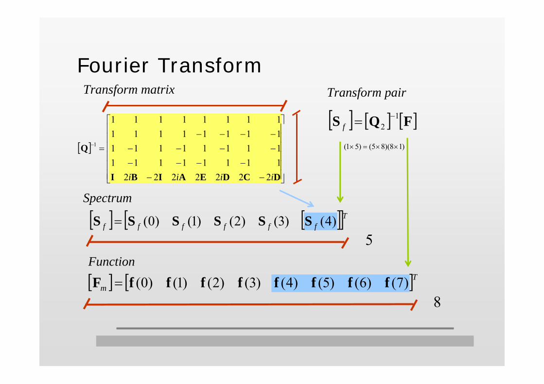
Fourier Transform
J. B. Fourier
Fourier G = R
∫∞
∞−
= dwewSxf wxf
π2)()(
∫∞
∞−
−= dxexfwS iwxf
π2)()(

Spectral Transforms
Walsh = Fourier on C2n
∑=w
f xwwalwSf ),()(
∑−=x
nf xwwalxfS ),()(2
Fourier on G = Finite non-Abelian
∑−
=
==1
0
),(),( ))()(())(()(K
ww
jif
ji xwTrxfx RSf
∑−
=
−−==1
0
1),(1),( )()())(()(g
uu
jiw
jiff uufgrwSw RS
J.B. Fourier J.L.Walsh
H.K.H.Weyl
|G| - finite
∑−
=
=1
0),()()(
g
wf xwwSxf χ
∑−
=
∗−=1
0
1 ),()()(g
xf xwxfgwS χ

Quaternion Group
2Q
⎥⎦
⎤⎢⎣
⎡=
1001
I ⎥⎦
⎤⎢⎣
⎡−
=1001
A ⎥⎦
⎤⎢⎣
⎡−=
1001
B
⎥⎦
⎤⎢⎣
⎡ −=
0110
C ⎥⎦
⎤⎢⎣
⎡=
0110
D ⎥⎦
⎤⎢⎣
⎡−
=0110
E01234567
11111111
1111
-1-1-1-1
1-11
-11
-11
-1
1-11
-1-11
-11
IiA-IiBC
-iDE
iD
x R0 R1 R2 R3 R4
r0 = 1 r1 = 1 r2 = 1 r3 = 1 r4 = 2
Group representationsrw = 1, rw = 2Coefficientscomplex numbers and (2×2) matrices
[ ]
⎥⎥⎥⎥⎥⎥
⎦
⎤
⎢⎢⎢⎢⎢⎢
⎣
⎡
−−−−−−
−−−−−−−−
=−
DCDEAIBI
Q
iiii 222222211111111111111111111111111111111
1
Transform matrix
Fourier Transform
Spectrum
Transform pair
[ ] [ ] [ ]FQS 12
−=f
[ ] [ ][ ]Tffffff )4()3()2()1()0( SSSSSS =
Function
[ ] [ ]Tm )7()6()5()4()3()2()1()0( ffffffffF =
5
8
)18)(85()51( ××=×

⎥⎥⎥⎥⎥⎥⎥⎥⎥⎥⎥
⎦
⎤
⎢⎢⎢⎢⎢⎢⎢⎢⎢⎢⎢
⎣
⎡
−−−−−−−−−
−−−−−−
−−−−−
=
0011110110111100111101101111
00111110011111
00111110011111
2
ii
ii
ii
ii
Q
Fourier Tranform Matrix
⎥⎥⎥⎥⎥⎥⎥⎥⎥⎥⎥
⎦
⎤
⎢⎢⎢⎢⎢⎢⎢⎢⎢⎢⎢
⎣
⎡
−−−−−−
−−−−−−
−−−−−−−−
=−
0000222222220000222200000000222211111111111111111111111111111111
811
2
iiiiii
iiQ
[ ]Tffffffff )7()6()5()4()3()2()1()0(=F
[ ]Tfffffffff SSSSSSSS )7()6()5()4()3()2()1()0(=S
No restrictions to entiries in FCould be matrices
8

Fourier Representations on Finite GroupsGroups of the same order, subgroups of different orders
i
n
iGG
1=×= ∏
=
=n
iigg
0
n = 7
n = 8
n = 9
n = 10
C27, C2C4
3, C2C82, C2
4q22, C4
2q2
C28, C4
4, C25q2, C2
5C8, C22q2
2, C4q22
C29, C2C4
4, C26q2, C2
6C8, C83, q2
3
C210, C4
5, C27C8, C2
4C82, C2C8
3, C27q2, C2
4q22, C2q2
3
The optimization method = Selecting suitable groups

# of non-zero coefficientsCalculation timeMemory
add5mul5sao2ex1010
C210
C210
C210
C27q2
5xp1 C2q22 C2C8
2
C24C8
2
C45
C2C83
C45
rd84 C44 C2
5C8clip C2
9 q23
C27
C28
C29
C210
C210
C210
C210
f In Coff. Time Memory789
10101010
C2
7
C2
8
C2
8
C2
10
C C2 4
7 3
C4
4
C C2 4
4
C4
5
C C2 8
2
C C2 8
5
C C2 8
6
C C2 8
7
C q2 2
4
C q2 2
5
C8
3
C C2 8
3
C q2 2
2
C q2 2
2 2
C q2 2
6
C q2 2
7
C q4 2
2
C q4 2
2
q2
3
C q2 2
3
200
150
100
50
0
350
300
250
200
150
100
50
0
1000
800
600
400
200
0
1400
1200
1000
800
600
400
200
0
n = 7
n = 8
n = 9
n = 10
Complexity of Fourier Representations

Coefficients and Bits
C27
cos(x)exp(x)ln(x)sin(x)tan(x)x2
x3
x4
x5
124128128128128103128111115
109914721485862
1421752859869931
240224240226238210220202236
15921904208711462102997
114812301360
248240248246248231246248246
164721522211143821561207530
16121686
182192192184192159168167178
1280562577953548851984
10531143
189144220210212189210102202
722562577715548683701709731
222192220228236189234231232
1477147757711855481007117713081396
C2C43 C2C8
2 C24 q2 C2q2
2 C24 q2
coeff. coeff. coeff. coeff. coeff. coeff.bits bits bits bits bits bitsf
av. 121 1083 226 1506 195 1626 168 883 186 660 220 1128

Bits and 1-Bits
C27
cos(x)exp(x)ln(x)sin(x)tan(x)x2
x3
x4
x5
360608656336501157323247262
109914721485862
1421752859869931
788992
1135726
102150617
770799
15921904208711462102997
114812301360
713888969558
1004394538464641
164721522211143821561207530
16121686
4963535
45320
274409383392
1280562577953548851984
10531143
1263535
16920
110136127125
722562577715548683701709731
6463535
61020
359582626617
1477147757711855481007117713081396
C2C43 C2C8
2 C24 q2 C2q2
2 C24 q2
1-bits 1-bits 1-bits 1-bits 1-bits 1-bitsbits bits bits bits bits bitsf
av. 3831083 6851506 7501626 277883 98660 3921128

Coefficients, Time, Memory add5mul5sao2 ex1010 fun10
1136
1024 1024826
26102
181620161823
2196
146418921638
31262
201619681984
41229
195620321980
1878
96015361343
25112
183017921791
32152
154019201740
av. 584.2 1156.6 1022.2 1252.2 1247.0 787.0 1110.0 1076.8101103414431457
18892
201244275
211113280317486
80130210280251
162129157170243
792502630617874
331280370491410
762538528403695
142184187187187
269266269269269
433386282433433
388386377385388
433430433433433
428426421438438
380379367388385
428426421438438
add5mul5sao2 ex1010 fun10 av.add5mul5sao2 ex1010 fun10 av.
301 200 281 190 172 683 376 585
177 268 402 458 432 430 380 430

Design Recommendations
usually (not always) requires smallest number of non-zero coefficients
C2iq2
r requires smallest number of bits and 1 bits
5xp1, rd84, sao2 C2q22, C4
4, C27
C2iC8
r, C4i fastes computations
C2n smallest memory
C2n

Closing Remarks
Relating of DSP and Switching theory assumes cahange of the underlying algebraic structures usually used in study of switching functionsDue to that
Different intepretations of existing methods and techniques
A unified way for extensions and genralizations of theory
Derivation of new results in Switching Thory by borrowing ideas from DSP

Acknowledgment