foundation engineering, inc. draft professional...
TRANSCRIPT

820 NW Cornell Avenue • Corvallis, Oregon 97330 • 541-757-7645
7857 SW Cirrus Drive, Bldg 24 • Beaverton, Oregon 97008 • 503-643-1541
Foundation Engineering, Inc. Professional Geotechnical Services Memorandum
Date: September 7, 2017
To: Unitarian Universalist Fellowship Corvallis
c/o Chris Bentley
From: James K. Maitland, P.E., G.E.
Erin J. Gillaspie, P.E.
Subject: Geotechnical Investigation - DRAFT
Project: UUFC Addition
Project 2171085
We have completed the geotechnical investigation for the above-referenced project.
Our findings and recommendations are summarized below.
BACKGROUND
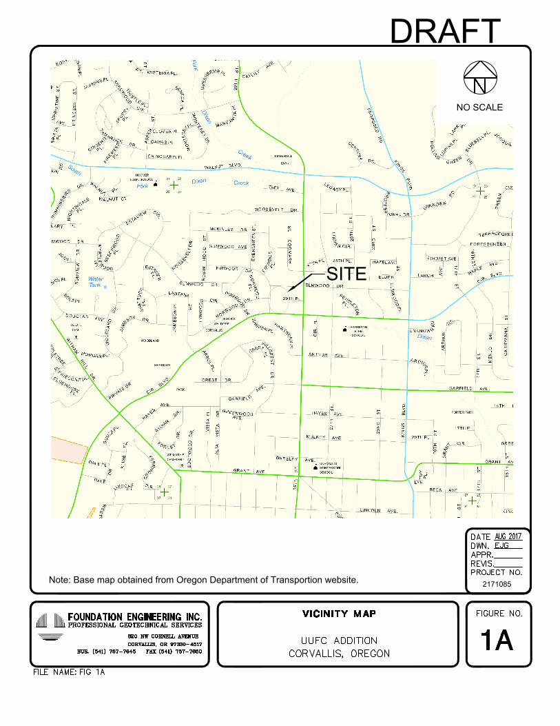
The Unitarian Universalist Fellowship of Corvallis (UUFC) is planning to expand their
facility located at 2945 NW Circle Blvd in Corvallis, Oregon. The expansion includes a
single-story, ±4,000 SF addition located north of the existing facility and an extension
of the parking lot in the northeast corner of the property. The planned addition includes
a social hall, kitchen, and storage area. The site location is shown on Figure 1A
(Appendix A).
UUFC retained Foundation Engineering to complete a geotechnical investigation and
infiltration testing for the planned addition. Per the Oregon Structural Specialty Code
(OSSC), the occupancy of the addition does not require a site specific seismic hazard
study. Our scope of work was outlined in a proposal dated August 15, 2017, and
authorized by a signed purchase order dated August 25, 2015.
FIELD EXPLORATION
We dug three exploratory test pits (TP-1 through TP-3) near the footprint of the
planned addition using a Hitachi 60 USB mini tracked excavator. Two additional test
pits (TP-4 and TP-5) were dug north of the addition for infiltration tests. The
approximate test pit locations are shown on Figure 2A (Appendix A).
The test pits extended to depths of ±3 to 9 feet. Representative soil samples were
obtained at selected depths for possible laboratory testing. Where feasible,
undrained shear strength measurements were made using a Field Vane shear device.
At most locations, the soil was too dry and stiff for vane shear tests.
DRAFT
UUFC Addition September 7, 2017
Geotechnical Investigation 2. Project 2171085
Corvallis, Oregon Unitarian Universalist Fellowship Corvallis
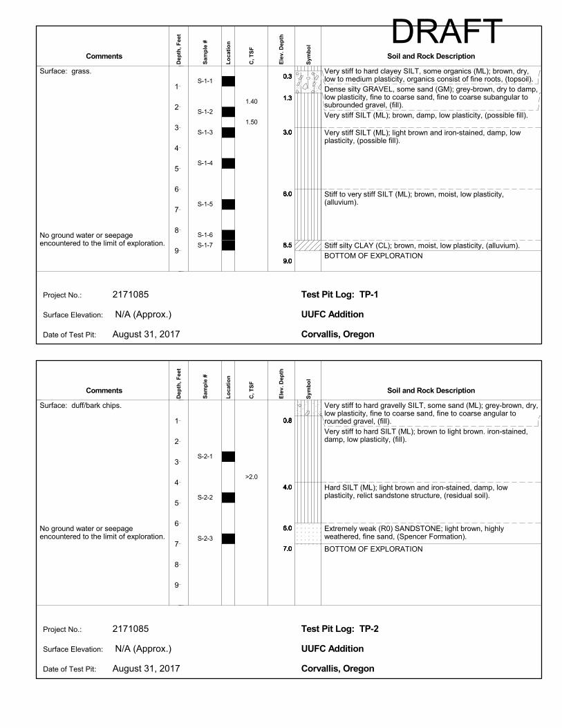
At each test pit, the soil profiles were logged and the absence of ground water was
noted. The soil profiles, sampling depths, and strength measurements are
summarized on the test pit logs (Appendix B). Upon completion of the excavations,
the test pits were backfilled with the excavated materials and the surface was graded
relatively smooth. No topographic information was available to estimate ground
surface elevations at the test pits.
DISCUSSION OF SITE CONDITIONS
Site Topography and Surface Conditions
The proposed addition will be built immediately north of the main building. The site
slopes gently uphill to the north and is covered with grass and scattered trees. We
estimate a ±4 to 5 foot difference in the ground surface elevation within the
footprint of the proposed addition.
The parking lot addition is planned at the northeast corner of the parcel, adjacent to
the existing parking that encompasses the northwest portion of the property. The
parking lot addition will be constructed over an area that is presently covered
primarily by an existing lawn.
The Benton County GIS office has prepared a map of historic streams that have been
filled in or altered. The map available online indicates a stream ran diagonally through
the parcel and crossed the footprint of the addition. Therefore, we expect to find fill
within the foundation area of the addition, once the site excavation is completed.
Subsurface Conditions
A general discussion of the soils encountered in the test pits is presented below. A
more detailed description of the subsurface conditions is provided on the test pit logs
(Appendix B).
Topsoil
Topsoil was encountered in test pits TP-1, TP-3, TP-4, and TP-5 to a depth of ±4 to
6 inches. The topsoil consists of very stiff to hard, dry silt with scattered organics and
gravel, and trace sand.
Site Fill
Site fill (or possible fill) was encountered to depths of 2.5 to 6 feet. The fill typically
consists of brown, very stiff to hard, dry, low plasticity silt with scattered small gravel
and trace sand. The appearance of the site fill was similar to the underlying soil,
possibly because it was generated from on-site grading. Therefore, the contact
between site fill and native soil is inferred and approximate. The site fill may have been
placed when the historic stream (described above) was filled in.
DRAFT

UUFC Addition September 7, 2017
Geotechnical Investigation 3. Project 2171085
Corvallis, Oregon Unitarian Universalist Fellowship Corvallis
Fine-Grained Alluvium
The native soil consists of brown, very stiff to hard, low to medium plasticity silt. A
vane shear test recorded at 3 feet in TP-1 indicated an undrained shear strength of
1.5 tsf. However, the soil was typically too stiff for vane tests.
Residual Soil
At TP-2, a 2-foot thick layer of residual soils was encountered at ±4 feet. The residual
soil represents material that has weathered in place from the underlying parent
formation. The residual soil consists of brown, hard, low plasticity silt with relict
sandstone/siltstone structure.
Bedrock
Extremely weak (R0), highly weathered to decomposed sandstone was encountered in
TP-2 at ±6 feet. The sandstone is part of the Spencer Formation, which underlies
much of the Witham Hills area. We anticipate it underlies the entire parcel at relatively
shallow depths. The upper portion of the bedrock could be readily excavated with the
small excavator.
Ground Water
No ground water or seepage was observed to the maximum depth of the test pits.
However, the soils moisture increased with depth. The mapped historic stream now
buried by site fill may be a conduit for subsurface seepage during periods of prolonged
wet weather.
LABORATORY TESTING
The laboratory work was limited to index tests (natural water content and Atterberg
limits) to classify the soils and estimate their engineering properties. Laboratory
index test results are summarized in Table 1C (Appendix C). Field vane shear test
results are summarized on the test pit logs.
INFILTRATION TESTING
Infiltration testing was performed on September 2, 2017 using the Encased Falling
Head infiltration test procedure outlined in Appendix D of the City of Corvallis
Stormwater Design Standards (2015). The tests were completed in TP-4 and TP-5 at
a depth of ±3 to 3.5 feet. Upon completion of the infiltration testing, the test pits and
trenches were backfilled with the excavated materials.
The results of the infiltration testing are provided in Appendix C and summarized in
Table 1.
DRAFT
UUFC Addition September 7, 2017
Geotechnical Investigation 4. Project 2171085
Corvallis, Oregon Unitarian Universalist Fellowship Corvallis
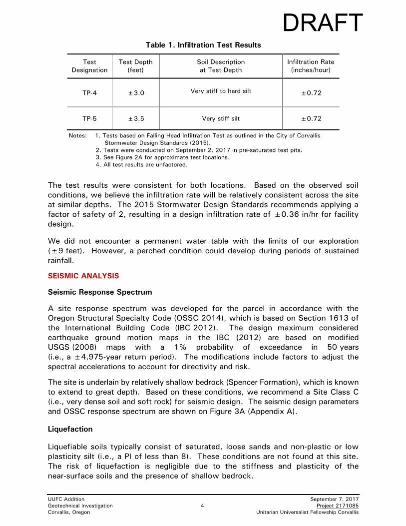
Table 1. Infiltration Test Results
Test
Designation
Test Depth
(feet)
Soil Description
at Test Depth
Infiltration Rate
(inches/hour)
TP-4 ±3.0 Very stiff to hard silt ±0.72
TP-5 ±3.5 Very stiff silt ±0.72
Notes: 1. Tests based on Falling Head Infiltration Test as outlined in the City of Corvallis
Stormwater Design Standards (2015).
2. Tests were conducted on September 2, 2017 in pre-saturated test pits.
3. See Figure 2A for approximate test locations.
4. All test results are unfactored.
The test results were consistent for both locations. Based on the observed soil
conditions, we believe the infiltration rate will be relatively consistent across the site
at similar depths. The 2015 Stormwater Design Standards recommends applying a
factor of safety of 2, resulting in a design infiltration rate of ±0.36 in/hr for facility
design.
We did not encounter a permanent water table with the limits of our exploration
(±9 feet). However, a perched condition could develop during periods of sustained
rainfall.
SEISMIC ANALYSIS
Seismic Response Spectrum
A site response spectrum was developed for the parcel in accordance with the
Oregon Structural Specialty Code (OSSC 2014), which is based on Section 1613 of
the International Building Code (IBC 2012). The design maximum considered
earthquake ground motion maps in the IBC (2012) are based on modified
USGS (2008) maps with a 1% probability of exceedance in 50 years
(i.e., a ±4,975-year return period). The modifications include factors to adjust the
spectral accelerations to account for directivity and risk.
The site is underlain by relatively shallow bedrock (Spencer Formation), which is known
to extend to great depth. Based on these conditions, we recommend a Site Class C
(i.e., very dense soil and soft rock) for seismic design. The seismic design parameters
and OSSC response spectrum are shown on Figure 3A (Appendix A).
Liquefaction
Liquefiable soils typically consist of saturated, loose sands and non-plastic or low
plasticity silt (i.e., a PI of less than 8). These conditions are not found at this site.
The risk of liquefaction is negligible due to the stiffness and plasticity of the
near-surface soils and the presence of shallow bedrock.
DRAFT

UUFC Addition September 7, 2017
Geotechnical Investigation 5. Project 2171085
Corvallis, Oregon Unitarian Universalist Fellowship Corvallis
ENGINEERING ANALYSIS AND DESIGN
Proposed Foundations and Loads
The planned addition will be a single-story, wood-framed structure with a
slab-on-grade concrete floor. Conventional continuous and spread footings are
planned. Foundation loads were not available at the time this report was prepared.
For the purpose of this report, we assumed maximum column loads would be in the
range of ±25 to 50 kips.
Bearing Capacity
The foundation soils were relatively dry and very stiff at the time of our exploration.
For these conditions, a very high theoretical bearing pressure could be calculated.
However, we believe the soils could soften during wet weather. Therefore, we have
recommended a presumptive (allowable) bearing pressure of 2,000 psf based on
assumed conditions during the winter and spring. This value assumes the base of the
foundation will be set at least 18 inches below the surrounding grade and will be
underlain by at least 6 inches of Select Fill extending at least 6 inches beyond the
footing edges. We have also assumed any unsuitable fill encountered during
construction will be removed and replaced with compacted Select Fill (defined below).
Settlement
A formal settlement analysis was not performed. However, due to the limited
thickness of existing site fill and native overburden, and the stiffness of the existing
foundation soils, we anticipate the total settlement of the building footings will be
less than ±½ inch, if foundation preparation is completed as recommended herein.
We estimate the maximum differential settlement between building footings will be
approximately half of the total settlement, or ±¼ inch.
Sliding Coefficient and Passive Resistance for Footings
We recommend a coefficient of friction of 0.5 between the base of the footings and
the crushed rock fill for sliding analysis. An equivalent fluid density of 150 pcf is
recommended to represent the potential passive resistance against the vertical face
of the footings. This assumes limited horizontal movement (i.e., less than 1 inch)
for service-level design. This presumptive (allowable) value assumes all footings will
be backfilled with compacted Select Fill extending at least 6 inches beyond the edge
of the footings.
Pavements
Pavement design was not part of the scope of work. We have provided the below
recommendations for subgrade preparation beneath the new parking lot expansion.
However, we assume the pavement section will match the existing one.
DRAFT

UUFC Addition September 7, 2017
Geotechnical Investigation 6. Project 2171085
Corvallis, Oregon Unitarian Universalist Fellowship Corvallis
RECOMMENDATIONS
UUFC indicated they would like to start construction of the planned addition in the
spring of 2018, but construction is more likely to occur during next summer.
Therefore, we have assumed site preparation and foundation construction will occur
during dry weather. We should be contacted if wet weather construction is
anticipated so we can make appropriate modifications to our recommendations.
General Earthwork and Materials Specifications
1. Select Fill as defined in this report should consist of ¾, 1, or 1½-inch
minus, clean, well-graded, crushed gravel or rock. We should be provided
a sample of the intended fill or a gradation curve for approval, prior to
delivery to the site.
2. Granular Site Fill as defined in this report should consist of 3 or 4-inch
minus, clean, (i.e., less than 5% passing the #200 U.S. Sieve),
well-graded, angular, crushed quarry rock. A material gradation should
be provided to us for approval prior to delivery to the site.
3. Fine-grained soil generated from on-site grading and demolition debris
should not be placed beneath new slabs or foundations, and should be
hauled from construction areas.
4. Drain Rock should consist of 2-inch minus, clean (less than 2% passing
the #200 sieve), open-graded crushed gravel or rock. The actual
gradation and maximum aggregate size will depend on availability by local
suppliers. We should be provided a sample of the intended fill and
gradation curve for approval, prior to delivery to the site.
5. Filter Fabric as defined in this report should consist of a non-woven
geotextile with a grab tensile strength greater than 200 lb., an apparent
opening size (AOS) of between #70 and 100 (US Sieve) and a permittivity
greater than 0.1 sec-1.
6. The Separation Geotextile (if required) should meet the minimum
requirements of an AASHTO M 288-06 geotextile for separation and have
Mean Average Roll Value (MARV) strength properties meeting the
requirements of an AASHTO M 288-06 Class 2, woven geotextile. We
should be provided a specification sheet on the selected geotextile for
approval prior to delivery to the site.
7. Moisture condition and compact all imported granular fill in loose lifts not
exceeding 12 inches. Thinner lifts may be required if light or
hand-operated equipment is used for compaction. Compact the subgrade
(during dry weather only) and all fill to a minimum of 95% relative
compaction. The maximum dry density of ASTM D 698 should be used
as the standard for estimating relative compaction.
DRAFT

UUFC Addition September 7, 2017
Geotechnical Investigation 7. Project 2171085
Corvallis, Oregon Unitarian Universalist Fellowship Corvallis
Field density tests should be run frequently to confirm adequate
compaction. The completed subgrade and building pad should be
proof-rolled using a loaded, 10-yd3 dump truck or another approved
vehicle. Adequate compaction based on proof-rolling should be confirmed
by a Foundation Engineering representative. Areas of pumping or
deflection observed beneath the truck wheels should be reworked, or
overexcavated and replaced with compacted Select Fill and proof-rolled
again.
8. Shoring should be provided in trenches according to OR-OSHA Standards
to protect workers from sloughing or caving soils. The site fill and native
overburden correspond to OR-OSHA soil Type B. However, the soil may
degrade to Type C during the winter or in the presence of perched ground
water. Shoring and worker safety are the sole responsibility of the
contractor.
Site Preparation and Foundation Construction
9. Strip the site to remove surface vegetation and roots. Deeper grubbing
may be required to remove roots from larger bushes or trees. Haul all
stripping from the site.
10. Excavate to the required grade. The extent of unsuitable fill (if any) due
to the filling of the original stream is not currently known. Therefore, the
depth and limits of the required overexcavation should be confirmed by
Foundation Engineering during construction. Replace the over-excavated
site fill with compacted Granular Site fill or a combination of Granular Site
Fill and Select Fill. We recommend a line item in the bid documents for
any overexcavation and replacement with granular fill under the footprint
of the building.
11. Compact the exposed subgrade as specified in Item 7 (dry weather only).
A Separation Geotextile is not required during dry weather, but is
recommended if slab and foundation construction extends into wet
weather.
12. Place and compact a minimum of 12 inches of Select Fill to create the
building pad. The building pad thickness may need to be increased to
24 inches in areas used by construction traffic or during wet weather
conditions.
13. Provide a minimum of 6 inches of compacted Select Fill beneath building
footings. Select Fill should extend at least 6 inches beyond the edge of
the footings. Overexcavation will be required for footing excavations
terminating in soft material or unsuitable fill. The limits and depth of any
overexcavation should be confirmed by Foundation Engineering.
DRAFT
UUFC Addition September 7, 2017
Geotechnical Investigation 8. Project 2171085
Corvallis, Oregon Unitarian Universalist Fellowship Corvallis
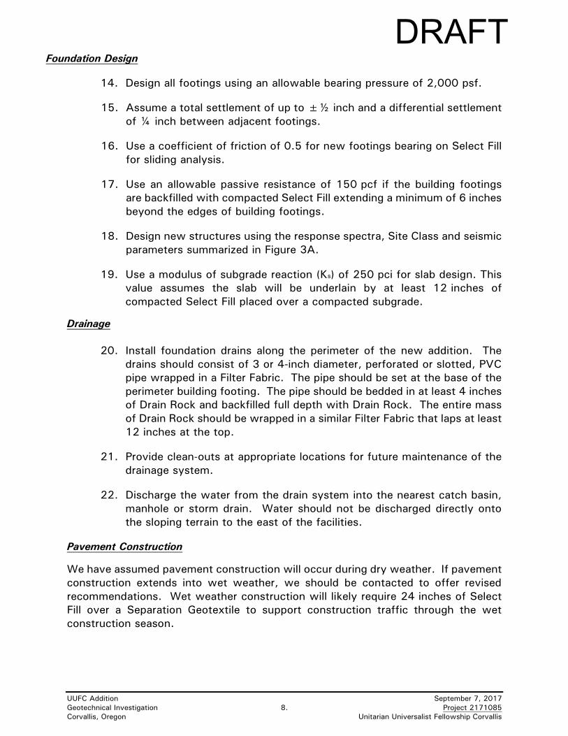
Foundation Design
14. Design all footings using an allowable bearing pressure of 2,000 psf.
15. Assume a total settlement of up to ±½ inch and a differential settlement
of ¼ inch between adjacent footings.
16. Use a coefficient of friction of 0.5 for new footings bearing on Select Fill
for sliding analysis.
17. Use an allowable passive resistance of 150 pcf if the building footings
are backfilled with compacted Select Fill extending a minimum of 6 inches
beyond the edges of building footings.
18. Design new structures using the response spectra, Site Class and seismic
parameters summarized in Figure 3A.
19. Use a modulus of subgrade reaction (Ks) of 250 pci for slab design. This
value assumes the slab will be underlain by at least 12 inches of
compacted Select Fill placed over a compacted subgrade.
Drainage
20. Install foundation drains along the perimeter of the new addition. The
drains should consist of 3 or 4-inch diameter, perforated or slotted, PVC
pipe wrapped in a Filter Fabric. The pipe should be set at the base of the
perimeter building footing. The pipe should be bedded in at least 4 inches
of Drain Rock and backfilled full depth with Drain Rock. The entire mass
of Drain Rock should be wrapped in a similar Filter Fabric that laps at least
12 inches at the top.
21. Provide clean-outs at appropriate locations for future maintenance of the
drainage system.
22. Discharge the water from the drain system into the nearest catch basin,
manhole or storm drain. Water should not be discharged directly onto
the sloping terrain to the east of the facilities.
Pavement Construction
We have assumed pavement construction will occur during dry weather. If pavement
construction extends into wet weather, we should be contacted to offer revised
recommendations. Wet weather construction will likely require 24 inches of Select
Fill over a Separation Geotextile to support construction traffic through the wet
construction season.
DRAFT

UUFC Addition September 7, 2017
Geotechnical Investigation 9. Project 2171085
Corvallis, Oregon Unitarian Universalist Fellowship Corvallis
Subgrade preparation and pavement construction during dry weather should be
completed as follows:
23. Excavate to the required subgrade elevation. Compact the subgrade
during dry weather as recommended in Item 7.
24. Place a Separation Geotextile on the prepared subgrade. The geotextile
should be placed as recommended in Item 6.
25. Provide a pavement section matching (at a minimum) the base rock and
asphaltic concrete thicknesses of the adjacent, existing parking area.
DESIGN REVIEW/CONSTRUCTION OBSERVATION/TESTING
We should be provided the opportunity to review all drawings and specifications that
pertain to site preparation and foundation construction. Site preparation will require
field evaluation of the soil conditions during excavation and the extent of any
unsuitable site fill. Construction observation should be provided by a Foundation
Engineering representative. Frequent field density tests should be run on all
compacted subgrade and Select Fill. We recommend that we be retained to provide
the necessary construction observation.
VARIATION OF SUBSURFACE CONDITIONS, USE OF THIS REPORT, AND WARRANTY
The analysis, conclusions and recommendations contained herein assume the
subsurface profiles encountered in the test pits are representative of the site
conditions. No changes in the enclosed recommendations should be made without
our approval. We will assume no responsibility or liability for any engineering
judgment, inspection or testing performed by others.
This report was prepared for the exclusive use of the Unitarian Universalist
Fellowship Corvallis, and its design consultants for the UUFC Addition project in
Corvallis, Oregon. Information contained herein should not be used for other sites or
for unanticipated construction without our written consent. This report is intended
for planning and design purposes. Contractors using this information to estimate
construction quantities, production rates, or costs do so at their own risk.
Climate conditions in western Oregon typically consist of wet weather for almost
half of the year (typically between mid-October and late May). The recommendations
for site preparation are not intended to represent any warranty (expressed or implied)
against the growth of mold, mildew or other organisms that grow in a humid or moist
environment.
Our services do not include any survey or assessment of potential surface
contamination or contamination of the soil or ground water by hazardous or toxic
materials. We assume that those services, if needed, have been completed by
others. Our work was done in accordance with generally accepted soil and
foundation engineering practices. No other warranty, expressed or implied, is made.
Attachments
DRAFT
UUFC Addition September 7, 2017
Geotechnical Investigation 11. Project 2171085
Corvallis, Oregon Unitarian Universalist Fellowship Corvallis
REFERENCES
AASHTO, 2006, Geotextile Specification for Highway Applications: American
Association of State Highway and Transportation Officials (AASHTO), M
288-06, 21 p.
IBC, 2012, International Building Code: International Code Council, Inc., Sections
1613 and 1803.3.
OR-OSHA, 2011, Oregon Administrative Rules Chapter 437, Division 3 -
Construction, Subdivision P – Excavations: Oregon Occupational Safety and
Health Division (OR-OSHA).
OSSC, 2014, Oregon Structural Specialty Code (OSSC): Based on the International
Code Council, Inc., 2012 IBC, Sections 1613 and 1803.3.
USGS, 2008, National Seismic Hazard Mapping Project, US Seismic Design Maps:
USGS website: http://earthquake.usgs.gov/designmaps/us/application.php.
DRAFT

Appendix A
Figures
Professional Geotechnical Services
Foundation Engineering, Inc.
DRAFT
2171085
NO SCALE
SITE
Note: Base map obtained from Oregon Department of Transportion website.
DRAFT

TP-4
TP-5
TP-1
TP-2
TP-3
2171085
402010
SCALE IN FEET
0
DRAFT

Notes:1. The Design Response Spectrum is based on IBC 2012 Section 1613.
2. The following parameters are based on the modified USGS 2008 maps provided
in IBC 2012/OSSC 2014:
Site Class= C Damping = 5%
SS = 0.97 Fa = 1.01 SMS = 0.98 SDS = 0.66
S1 = 0.48 Fv = 1.32 SM1 = 0.63 SD1 = 0.42
3. SS and S1 values indicated in Note 2 are the mapped, risk-targeted maximum considered
earthquake spectral acclerations for 1% probability of exceedence in 50 years.
4. Fa and Fv were established based on IBC 2012, Tables 1613.3.3(1) and 1613.3.3(2)
using the selected SS and S1 values. SDS and SD1 values include a 2/3 reduction on
SMS and SM1 as discussed in IBC 2012 Section 1613.3.4.
5. Site location is: Latitude 44.5869, Longitude -123.2850.
Corvallis, Oregon
FIGURE 3A
UUFC AdditionIBC 2012/OSSC 2014 SITE RESPONSE SPECTRUM
Project 2171085
0.0
0.1
0.2
0.3
0.4
0.5
0.6
0.7
0 0.5 1 1.5 2 2.5 3
Spec
tral
Acc
eler
atio
n, S
a(g
)
Period (seconds)
IBC 2012/OSSC 2014Response Spectrum
DRAFT
Appendix B
Test Pit Logs
Professional Geotechnical Services
Foundation Engineering, Inc.
DRAFT
DRAFT

DRAFT
1.40
1.50
0.3
1.3
3.0
6.0
8.5
9.0
0.3
1.3
3.0
6.0
8.5
9.0
0.3
1.3
3.0
6.0
8.5
9.0
Surface: grass.
No ground water or seepageencountered to the limit of exploration.
Very stiff to hard clayey SILT, some organics (ML); brown, dry,low to medium plasticity, organics consist of fine roots, (topsoil).Dense silty GRAVEL, some sand (GM); grey-brown, dry to damp,low plasticity, fine to coarse sand, fine to coarse subangular tosubrounded gravel, (fill).Very stiff SILT (ML); brown, damp, low plasticity, (possible fill).
Very stiff SILT (ML); light brown and iron-stained, damp, lowplasticity, (possible fill).
Stiff to very stiff SILT (ML); brown, moist, low plasticity,(alluvium).
Stiff silty CLAY (CL); brown, moist, low plasticity, (alluvium).BOTTOM OF EXPLORATION
S-1-1
S-1-2
S-1-3
S-1-4
S-1-5
S-1-6
S-1-7
0.3
1.3
3.0
6.0
8.5
9.0
0.3
1.3
3.0
6.0
8.5
9.0
Corvallis, Oregon
Surface Elevation:
Date of Test Pit:
Project No.:
Ele
v. D
epth
Sym
bo
l N/A (Approx.) UUFC Addition
August 31, 2017
2171085 Test Pit Log: TP-1
Comments
Dep
th,
Fee
t
Sam
ple
#
Lo
cati
on
Soil and Rock Description
1
2
3
4
5
6
7
8
9C
, TS
F
>2.0
0.8
4.0
6.0
7.0
0.8
4.0
6.0
7.0
0.8
4.0
6.0
7.0
Surface: duff/bark chips.
No ground water or seepageencountered to the limit of exploration.
Very stiff to hard gravelly SILT, some sand (ML); grey-brown, dry,low plasticity, fine to coarse sand, fine to coarse angular torounded gravel, (fill).Very stiff to hard SILT (ML); brown to light brown. iron-stained,damp, low plasticity, (fill).
Hard SILT (ML); light brown and iron-stained, damp, lowplasticity, relict sandstone structure, (residual soil).
Extremely weak (R0) SANDSTONE; light brown, highlyweathered, fine sand, (Spencer Formation).
BOTTOM OF EXPLORATION
S-2-1
S-2-2
S-2-3
0.8
4.0
6.0
7.0
0.8
4.0
6.0
7.0
Corvallis, Oregon
Surface Elevation:
Date of Test Pit:
Project No.:
Ele
v. D
epth
Sym
bo
l
N/A (Approx.) UUFC Addition
August 31, 2017
2171085 Test Pit Log: TP-2
Comments
Dep
th,
Fee
t
Sam
ple
#
Lo
cati
on
Soil and Rock Description
1
2
3
4
5
6
7
8
9
C, T
SF
DRAFT

2.00
>2.5
0.5
2.5
6.0
8.0
0.5
2.5
6.0
8.0
0.5
2.5
6.0
8.0
Surface: grass.
No ground water or seepageencountered to the limit of exploration.
Very stiff SILT, some gravel and organics, trace sand (CL);brown, dry, low plasticity, fine to coarse sand, fine to coarsesubangular to subrounded gravel, organics consist of roots up to±½-inch diameter, blocky structure, (topsoil).Very stiff to hard SILT, some gravel, trace sand (ML); brown,damp, low plasticity, (fill).Hard SILT (ML); light brown to brown, iron-stained, damp, lowplasticity, (alluvium).
Very stiff SILT (ML); brown and iron-stained, moist, low plasticity,(alluvium).
BOTTOM OF EXPLORATION
S-3-1
S-3-2
S-3-3
S-3-4
S-3-5
0.5
2.5
6.0
8.0
0.5
2.5
6.0
8.0
Corvallis, Oregon
Surface Elevation:
Date of Test Pit:
Project No.:
Ele
v. D
epth
Sym
bo
l N/A (Approx.) UUFC Addition
August 31, 2017
2171085 Test Pit Log: TP-3
Comments
Dep
th,
Fee
t
Sam
ple
#
Lo
cati
on
Soil and Rock Description
1
2
3
4
5
6
7
8
9C
, TS
F
0.3
3.0
0.3
3.0
0.3
3.0
Surface: grass.
No ground water or seepageencountered to the limit of exploration.
Very stiff SILT, some organics (ML); brown, dry to damp, lowplasticity, organics consist of fine roots, blocky structure,(topsoil).Very stiff SILT (ML); light brown to brown and iron-stained, damp,low plasticity, (alluvium).
BOTTOM OF EXPLORATION
0.3
3.0
0.3
3.0
Corvallis, Oregon
Surface Elevation:
Date of Test Pit:
Project No.:
Ele
v. D
epth
Sym
bo
l
N/A (Approx.) UUFC Addition
August 31, 2017
2171085 Test Pit Log: TP-4
Comments
Dep
th,
Fee
t
Sam
ple
#
Lo
cati
on
Soil and Rock Description
1
2
3
4
5
6
7
8
9
C, T
SF
DRAFT

0.3
3.5
0.3
3.5
0.3
3.5
Surface: grass.
No ground water or seepageencountered to the limit of exploration.
Very stiff SILT, some organics (ML); brown, dry, low plasticity,organics consist of fine roots, blocky structure, (topsoil).Very stiff SILT, scattered organics (ML); brown, damp, lowplasticity, organics consist of roots up to ±1-inch diameter andwood debris, (alluvium).
BOTTOM OF EXPLORATION
0.3
3.5
0.3
3.5
Corvallis, Oregon
Surface Elevation:
Date of Test Pit:
Project No.:
Ele
v. D
epth
Sym
bo
l N/A (Approx.) UUFC Addition
August 31, 2017
2171085 Test Pit Log: TP-5
Comments
Dep
th,
Fee
t
Sam
ple
#
Lo
cati
on
Soil and Rock Description
1
2
3
4
5
6
7
8
9C
, TS
F
DRAFT

Appendix C
Field and Laboratory Test Results
Professional Geotechnical Services
Foundation Engineering, Inc.
DRAFT

Foundation Engineering, Inc. UUFC Addition Project 2171085
Table 1C. Natural Water Contents and Atterberg Limits
Sample Number
Sample Depth (ft)
Natural Water Content (percent)
LL PL PI USCS
Classification
S-1-2 2.0 – 2.5 16.4 41 29 12 ML
S-1-4 4.5 – 5.0 18.6
S-1-5 6.5 – 7.0 35.7
S-1-7 8.5 – 9.0 34.1
S-2-1 2.5 – 3.0 13.2
S-2-2 4.5 – 5.0 22.0
S-3-3 4.5 – 5.0 20.5 36 27 9 ML
S-3-4 6.5 – 7.0 22.2
S-3-5 7.5 – 8.0 26.4
DRAFT

Foundation Engineering, Inc.UUFC AdditionProject 2171085
Test Hole Number: TP-4
Trial Number: 1Time: Timer Interval Measurement Drop in water level Infilteration Rate Remakrs
(min) (feet) (feet) (in/hr)7:17 AM 0 3.98 - - Filled with 6'' of water
20 4.03 0.05 1.8040 - - -60 4.11 0.08 1.4480 4.15 0.04 1.44
100 4.19 0.04 1.449:17 AM 120 4.22 0.03 1.08
Adjusted to 6'' level for Trial 2
Trial Number: 2Time: Timer Interval Measurement Drop in water level Infilteration Rate Remakrs
(min) (feet) (feet) (in/hr)9:24 AM 0 3.96 - - Filled with 6'' of water
20 4.00 0.04 1.4440 4.03 0.03 1.0860 4.06 0.03 1.0880 4.09 0.03 1.08
100 4.12 0.03 1.0811:24 AM 120 4.15 0.03 1.08
Adjusted to 6'' level for Trial 3
Trial Number: 3Time: Timer Interval Measurement Drop in water level Infilteration Rate Remakrs
(min) (feet) (feet) (in/hr)11:27 AM 0 3.99 - - Filled with 6'' of water
20 4.02 0.03 1.0840 4.05 0.03 1.0860 4.08 0.03 1.0880 4.11 0.03 1.08
100 4.14 0.03 1.081:27 PM 120 4.16 0.02 0.72 Test Infiltration Rate
DRAFT

Foundation Engineering, Inc.UUFC AdditionProject 2171085
Test Hole Number: TP-5
Trial Number: 1Time: Timer Interval Measurement Drop in water level Infilteration Rate Remakrs
(min) (feet) (feet) (in/hr)7:23 AM 0 3.83 - - Filled with 6'' of water
20 3.89 0.06 2.1640 3.95 0.06 2.1660 4.00 0.05 1.880 4.04 0.04 1.44
100 4.08 0.04 1.449:23 AM 120 4.11 0.03 1.08
Adjusted to 6'' level for Trial 2
Trial Number: 2Time: Timer Interval Measurement Drop in water level Infilteration Rate Remakrs
(min) (feet) (feet) (in/hr)9:23 AM 0 3.89 - - Filled with 6'' of water
20 3.93 0.04 1.4440 3.97 0.04 1.4460 4.01 0.04 1.4480 4.05 0.04 1.44
100 4.08 0.03 1.0811:23 AM 120 4.10 0.02 0.72
Adjusted to 6'' level for Trial 3
Trial Number: 3Time: Timer Interval Measurement Drop in water level Infilteration Rate Remakrs
(min) (feet) (feet) (in/hr)11:28 AM 0 3.89 - - Filled with 6'' of water
20 3.92 0.03 1.0840 3.95 0.03 1.0860 3.98 0.03 1.0880 4.00 0.02 0.72
100 4.02 0.02 0.721:28 PM 120 4.04 0.02 0.72 Test Infiltration Rate
DRAFT