draft geotechnical report magnolia bridge replacement
TRANSCRIPT

Draft Geotechnical ReportMagnolia Bridge Replacement Project –
Concept DesignSeattle, Washington
November 28, 2006
Submitted To: Mr. Pete Smith
HNTB 600 108th Avenue NE, Suite 400
Bellevue, Washington 98004
By:Shannon & Wilson, Inc.
400 N 34th Street, Suite 100 Seattle, Washington 98103
21-1-09759-011 DRAFT

TABLE OF CONTENTS
Page
1.0 INTRODUCTION..................................................................................................................1
2.0 TASK 5 OVERVIEW ............................................................................................................1
3.0 SUBSURFACE CONDITIONS.............................................................................................2
4.0 GEOTECHNICAL RECOMMENDATIONS FOR CONCEPTUAL DESIGN ...................2 4.1 General .......................................................................................................................2 4.2 Ground Improvement .................................................................................................3
4.2.1 Recommended Depths and Extents .............................................................3 4.2.2 Cost and Feasibility......................................................................................4 4.2.3 Consideration of Existing Bridge Foundations............................................4 4.2.4 Ground Improvement West of Proposed Station 35+00..............................4
4.3 Foundation Recommendations...................................................................................5 4.3.1 Axial Capacity .............................................................................................5 4.3.2 Cost and Feasibility......................................................................................7 4.3.3 Construction Considerations........................................................................7 4.3.4 Integrity Testing of Drilled Shafts ...............................................................8
4.4 West Approach Abutment ..........................................................................................8 4.4.1 Proposed West Abutment ............................................................................8 4.4.2 Existing West Abutment ..............................................................................9
4.5 Mechanically Stabilized Earth (MSE) Walls for Approach Fill Embankments ........9 4.5.1 Facings .......................................................................................................10 4.5.2 Reinforced and Retained Backfill Materials..............................................10 4.5.3 Drainage Provisions ...................................................................................10
4.6 Removal and Replacement of Approach Fill West of 15th Avenue West................10 4.7 Temporary Structures ...............................................................................................11
4.7.1 MSE Temporary Ramps ............................................................................11 4.7.2 Timber Pile-supported Staging ..................................................................11 4.7.3 Mat Foundation-supported Staging............................................................12
4.8 Fill Placement at Jacobs Lake ..................................................................................12 4.9 Potential Contamination Issues ................................................................................13
5.0 LIMITATIONS ....................................................................................................................13
TABLE
Recommended Extent and Depth of Ground Improvement
LIST OF FIGURES
Figure No.
1 Site and Exploration Plan, Bridge Rehabilitation Alternative 2 Generalized Subsurface Profile, Bridge Rehabilitation Alternative 3 Updated Estimated Static Allowable Axial Capacities, Bents 63 to 74 (Drilled
Shafts) 4 Updated Estimated Static Allowable Axial Capacities, Bents 63 to 74 (Steel Piles) 5 Updated Estimated Static Ultimate Uplift Capacities, Bents 63 to 74 6 Updated Estimated Static Allowable Axial Capacities, Bents 47 to 62 (Drilled
Shafts) 7 Updated Estimated Static Allowable Axial Capacities, Bents 47 to 62 (Steel Piles) 8 Updated Estimated Static Ultimate Uplift Capacities, Bents 47 to 62 9 Updated Estimated Static Allowable Axial Capacities, Bents 26 to 46 (Drilled
Shafts) 10 Updated Estimated Static Allowable Axial Capacities, Bents 26 to 46 (Steel Piles) 11 Updated Estimated Static Ultimate Uplift Capacities, Bents 26 to 46 12 Updated Estimated Static Allowable Axial Capacities, Bents 18 to 25 (Drilled
Shafts) 13 Updated Estimated Static Allowable Axial Capacities, Bents 18 to 25 (Steel Piles) 14 Updated Estimated Static Ultimate Uplift Capacities, Bents 18 to 25 15 Updated Estimated Static Allowable Axial Capacities, Bents 1 to 18 (Drilled
Shafts) 16 Updated Estimated Static Allowable Axial Capacities, Bents 1 to 18 (Steel Piles) 17 Updated Estimated Static Ultimate Uplift Capacities, Bents 1 to 18 18 Estimated Static Allowable Axial Capacities, East of Bent 1 (Drilled Shafts) 19 Estimated Static Allowable Axial Capacities, East of Bent 1 (Steel Piles) 20 Estimated Static Ultimate Uplift Capacities, East of Bent 1 21 Estimated Static Allowable Axial Capacities, 15th Ave West (Drilled Shafts) 22 Estimated Static Allowable Axial Capacities, 15th Ave West (Steel Piles) 23 Estimated Static Ultimate Uplift Capacities, 15th Ave West 24 Estimated Seismic Ultimate Axial Capacities, Bents 63 to 74 (Drilled Shafts) 25 Estimated Seismic Ultimate Axial Capacities, Bents 63 to 74 (Steel Piles) 26 Estimated Seismic Ultimate Uplift Capacities, Bents 63 to 74 27 Estimated Seismic Ultimate Axial Capacities, Bents 47 to 62 (Drilled Shafts) 28 Estimated Seismic Ultimate Axial Capacities, Bents 47 to 62 (Steel Piles) 29 Estimated Seismic Ultimate Uplift Capacities, Bents 47 to 62 30 Estimated Seismic Ultimate Axial Capacities, Bents 26 to 46 (Drilled Shafts) 31 Estimated Seismic Ultimate Axial Capacities, Bents 26 to 46 (Steel Piles) 32 Estimated Seismic Ultimate Uplift Capacities, Bents 26 to 46 33 Estimated Seismic Ultimate Axial Capacities, Bents 18 to 25 (Drilled Shafts) 34 Estimated Seismic Allowable Axial Capacities, Bents 18 to 25 (Steel Piles) 35 Estimated Seismic Ultimate Uplift Capacities, Bents 18 to 25 36 Estimated Seismic Ultimate Axial Capacities, Bents 1 to 18 (Drilled Shafts)
LIST OF FIGURES (cont.) Figure No.
37 Estimated Seismic Ultimate Axial Capacities, Bents 1 to 18 (Steel Piles) 38 Estimated Seismic Ultimate Uplift Capacities, Bents 1 to 18 39 Estimated Seismic Ultimate Axial Capacities, East of Bent 1 (Drilled Shafts) 40 Estimated Seismic Ultimate Axial Capacities, East of Bent 1 (Steel Piles) 41 Estimated Seismic Ultimate Uplift Capacities, East of Bent 1 42 Estimated Seismic Ultimate Axial Capacities, 15th Ave West (Drilled Shafts) 43 Estimated Seismic Ultimate Axial Capacities, 15th Ave West (Steel Piles) 44 Estimated Seismic Ultimate Uplift Capacities, 15th Ave West 45 Ultimate Footing Bearing Resistance Versus Effective Footing Width
APPENDIX
Important Information About Your Geotechnical Report

21-1-09759-011-R1_edited.doc/wp/LMM 21-1-09759-011 DRAFT
1
DRAFT GEOTECHNICAL REPORT MAGNOLIA BRIDGE REPLACEMENT PROJECT – CONCEPT DESIGN
SEATTLE, WASHINGTON
1.0 INTRODUCTION
This report summarizes our geotechnical recommendations developed during Concept Design (Task 5) of the Magnolia Bridge Replacement Project in Seattle, Washington. Our recommendations are based on existing subsurface information, conversations with experienced Contractors, and our experience on similar projects. Our engineering analyses, recommendations, and discussions should be considered conceptual; additional field explorations and analyses will be required during the Type, Size, and Location (TS&L) design phase.
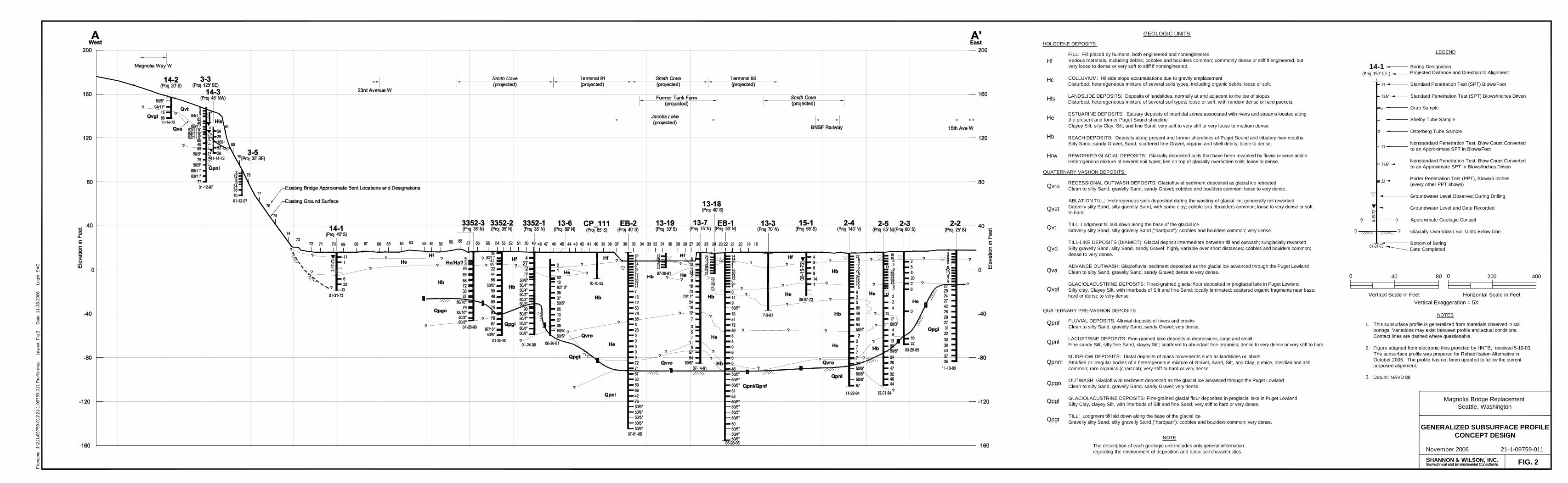
A site plan is provided in Figure 1, Site and Exploration Plan, Concept Design. Additionally, a subsurface profile presenting our interpretation of the existing subsurface and geologic conditions at the site is shown in Figure 2, Generalized Subsurface Profile, Concept Design.
2.0 TASK 5 OVERVIEW
During Task 5, the project team evaluated a number of alignment, structure, and construction sequencing alternatives before selecting the preferred alternative for TS&L design. Our scope of services for this task included developing updated foundation design recommendations; providing consultation for items such as ground improvement and construction-related issues; and preparing this report. In addition to these scope items, we attended four meetings to discuss Concept Design issues.
It is our understanding that the selected structure type for TS&L design is a concrete box structure supported on drilled shafts, which will be located just south of the existing bridge structure as shown in Figure 1. Demolition of the existing structure and construction of the proposed new structure will be coordinated so that traffic closure time is kept to a minimum. During TS&L design, the project team will consider using ground improvement, either stone columns, compaction grouting, or a combination of the two, at each proposed pier, from the east end of the 15th Avenue NW Overpass to the existing Pier 9 of the mainline bridge. Portions of the 23rd Avenue West on-ramp will be constructed overwater at Smith Cove, as well as portions

21-1-09759-011-R1_edited.doc/wp/LMM 21-1-09759-011 DRAFT
2
of the new mainline structure over Jacobs Lake. Temporary staging will be necessary to construct the proposed structure. Temporary structures will also be necessary during construction, so that traffic can be rerouted and traffic disruptions are minimized.
3.0 SUBSURFACE CONDITIONS
Additional subsurface explorations and laboratory testing were not performed during Task 5. Recommendations provided to the project team during this phase of work are based on existing subsurface information, which consists of existing data presented in our geotechnical data report submitted in December 2003, and two additional subsurface explorations and subsequent laboratory testing performed for the Rehabilitation Alternative in 2005. The Generalized Subsurface Profile, which was enclosed in our Rehabilitation Alternative letter dated October 13, 2005, has been included in this report as Figure 2 for reference. As mentioned earlier, additional field explorations and engineering analyses will be required during the TS&L design phase.
4.0 GEOTECHNICAL RECOMMENDATIONS FOR CONCEPTUAL DESIGN
4.1 General
As mentioned previously, as part of Task 5, Concept Design, the project team evaluated a number of alignment, structure, and construction sequencing alternatives before selecting the preferred alternative for TS&L design. During the evaluation period, the team concentrated mainly on two structure alternatives - the prestressed girder and the concrete box and steel girder options. We provided geotechnical consultation to the project team through email and telephone correspondence, and at team meetings, as concept design progressed. Consultation was provided for the following geotechnical items:
Estimated extent, depth, type, and impacts of ground improvement.
Cost, feasibility, and construction time for various foundation and ground improvement alternatives.
Construction impacts related to the removal of existing foundations and/or preserving the existing foundations during construction.
Mechanically Stabilized Earth (MSE) walls for approach fill embankments.
Removal and replacement of existing approach fill embankment retained by concrete retaining walls west of 15th Avenue West.

21-1-09759-011-R1_edited.doc/wp/LMM 21-1-09759-011 DRAFT
3
Temporary ramp wall alternatives and impacts to existing structures, such as settlement.
Temporary staging foundation recommendations.
Geotechnical impacts resulting from filling Jacobs Lake.
Contaminated soil and groundwater handling, testing, and disposal, and impacts resulting from proposed construction.
The following sections summarize our geotechnical recommendations provided to the project team during Concept Design. As the project team evaluated different design schemes, we provided recommendations pertaining to the above geotechnical issues, as requested. Consultation provided to the project team was based on the existing subsurface information and our experience with similar projects. As a result, our engineering analyses, recommendations, and discussions for Task 5 should be considered conceptual. Additional field explorations and analyses will be required during the TS&L design phase.
4.2 Ground Improvement
Please refer our Memorandum No. 1, dated September 26, 2003, for a generalized overview of compaction grouting and vibro-replacement (i.e., stone columns).
4.2.1 Recommended Depths and Extents
Recommended ground improvement depths and extents for stone column installation and compaction grouting have been summarized in the attached Table, Ground Improvement Recommendations. We assumed that ground improvement would be performed to the bottom of the loose, potentially liquefiable beach deposits and the upper loose and/or soft Estuarine deposits underlying the project site. Underlying these soils, dense beach deposits exist overlying a soft Estuarine layer of varying thickness. Ground improvement of the lower estuarine layer underlying the beach deposits is not recommended, as advancement through the overlying dense beach deposits would be difficult and not cost effective. In addition, the lower Estuarine layer consists of primarily cohesive soils that have a low liquefaction potential.
The depths provided in the attached Table are based on the existing subsurface information available at this time, and will be re-evaluated when additional explorations are performed.
21-1-09759-011-R1_edited.doc/wp/LMM 21-1-09759-011 DRAFT
4
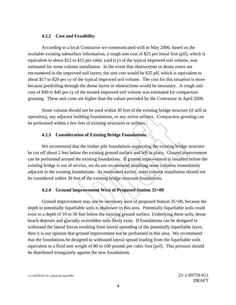
4.2.2 Cost and Feasibility
According to a local Contractor we communicated with in May 2006, based on the available existing subsurface information, a rough unit cost of $25 per lineal foot (plf), which is equivalent to about $12 to $15 per cubic yard (cy) of the typical improved soil volume, was estimated for stone column installation. In the event that obstructions or dense zones are encountered in the improved soil layers, the unit cost would be $35 plf, which is equivalent to about $17 to $20 per cy of the typical improved soil volume. The cost for this situation is more because predrilling through the dense layers or obstructions would be necessary. A rough unit cost of $40 to $45 per cy of the treated improved soil volume was estimated for compaction grouting. These unit costs are higher than the values provided by the Contractor in April 2006.
Stone column should not be used within 30 feet of the existing bridge structure (if still in operation), any adjacent building foundations, or any active utilities. Compaction grouting can be performed within a few feet of existing structures or utilities.
4.2.3 Consideration of Existing Bridge Foundations
We recommend that the timber pile foundations supporting the existing bridge structure be cut off about 2 feet below the existing ground surface and left in place. Ground improvement can be performed around the existing foundations. If ground improvement is installed before the existing bridge is out of service, we do not recommend installing stone columns immediately adjacent to the existing foundations. As mentioned earlier, stone column installation should not be considered within 30 feet of the existing bridge structure foundations.
4.2.4 Ground Improvement West of Proposed Station 35+00
Ground improvement may not be necessary west of proposed Station 35+00, because the depth to potentially liquefiable soils is shallower in this area. Potentially liquefiable soils could exist to a depth of 10 to 30 feet below the existing ground surface. Underlying these soils, dense beach deposits and glacially overridden soils likely exist. If foundations can be designed to withstand the lateral forces resulting from lateral spreading of the potentially liquefiable layer, then it is our opinion that ground improvement not be performed in this area. We recommend that the foundations be designed to withstand lateral spread loading from the liquefiable soils equivalent to a fluid unit weight of 80 to 100 pounds per cubic foot (pcf). This pressure should be distributed triangularly against the new foundations.

21-1-09759-011-R1_edited.doc/wp/LMM 21-1-09759-011 DRAFT
5
4.3 Foundation Recommendations
4.3.1 Axial Capacity
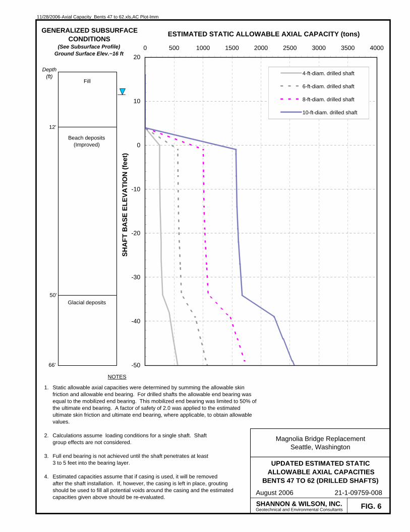
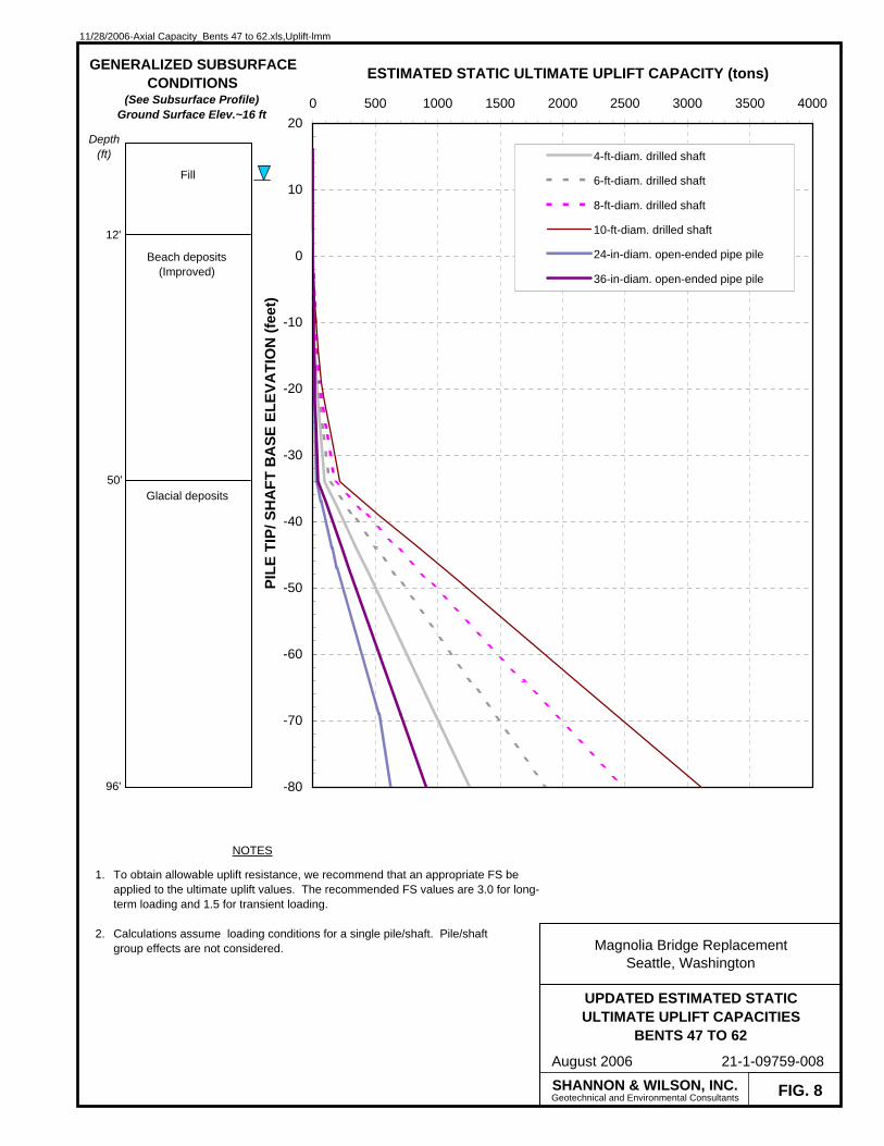
Axial capacities for proposed drilled shaft foundations were provided during the evaluation of the Rehabilitation Alternative in 2005. Our previous axial capacity analyses were performed for 6-foot-diameter drilled shafts based on the available subsurface soil information and our experience with similar soil and project conditions. Ground improvement of the beach deposits was considered in these analyses. Static soil properties and loading conditions only were evaluated. For this Task, the static axial capacities previously provided for 6-foot-diameter drilled shafts were updated, and two additional segments - East of Bent 1 and 15th Avenue West – were analyzed. In addition, we evaluated three more shaft sizes – 4-, 8-, and 10-foot-diameter drilled shafts, and 24- and 36-inch-diameter, steel pipe piles, driven open-ended. The seismic loading condition was also evaluated; seismic soil properties and downdrag due to seismically induced settlement were considered when developing the seismic axial capacities.
Seven segments were evaluated - Bents 63 to 74, Bents 47 to 62, Bents 26 to 46, Bents 18 to 25, Bents 1 to 18, East of Bent 1, and 15th Avenue West. For all seven segments, the following figures were developed:
Estimated Static Allowable Axial Capacities (Drilled Shafts) Estimated Static Allowable Axial Capacities (Steel Pipe Piles) Estimated Static Ultimate Uplift Capacities Estimated Seismic Ultimate Axial Capacities (Drilled Shafts) Estimated Seismic Ultimate Axial Capacities (Steel Pipe Piles) Estimated Seismic Ultimate Uplift Capacities
Static allowable axial capacities and ultimate uplift capacities are presented in Figures 3 through 23; seismic ultimate axial capacities and ultimate uplift capacities are provided in Figures 24 through 44. Axial capacity analyses were performed using an in-house computer program that determines axial compressive capacity by summing skin friction along the side of the shaft and end bearing at its base. For the static loading case, static axial capacities were presented as allowable for Allowable Stress Design (ASD). We understand that final design will be performed using Load Resistance Factor Design (LRFD); however, since the seismic case is likely to control, the static axial capacities provided in this report were not updated and presented as ultimate for use in LRFD design. Static axial capacities provided in the TS&L design phase, however, will be presented as ultimate for use in LRFD design. For the driven steel pipe piles, a

21-1-09759-011-R1_edited.doc/wp/LMM 21-1-09759-011 DRAFT
6
factor-of-safety (FS) of 2.0 was applied to both the ultimate static skin friction and end bearing values, before summing the two to obtain the static allowable axial capacity. For the drilled shafts, an FS of 2.0 was applied to the ultimate static skin friction and combined with the mobilized end bearing, to obtain the static allowable axial capacity. The mobilized end bearing is typically a function of drilled shaft size and anticipated settlement. However, for this loading case, it was limited to 50 percent of the ultimate end bearing, which is equivalent to applying a FS of 2.0 to the ultimate value.
For the seismic loading case, seismic axial capacities, which were determined by summing the ultimate skin friction and end bearing values, were presented as ultimate for LRFD design. For drilled shafts, the ultimate end bearing was equal to the mobilized end bearing. Mobilized end bearing values for drilled shafts in nonglacial soils were determined based on assumed settlements for varying shaft sizes. Mobilized end bearing values for drilled shafts in glacially overridden soils were based on maximum assumed mobilized end bearing values. We recommend that a resistance factor of 1.0 be applied to the ultimate axial capacities when evaluating the extreme limit state in LRFD design.
Ultimate uplift capacities were provided for the both the static and seismic loading conditions. For the static loading condition, we recommend that FS values of 3.0 and 1.5 be considered for long term and transient loading, respectively, in ASD. For the seismic loading condition, we recommend applying a resistance factor of 1.0 when considering the extreme limit state in LRFD design.
Ground improvement of site soils was considered when determining the static properties for axial capacity analyses. Downdrag forces associated with significant seismically-induced settlement of the soft clay and silt (lower Estuarine deposits) underlying the site were also considered. During an earthquake, the estuarine deposits may experience a reduction in shear strength, resulting in some settlement of the layer. Downdrag forces associated with the downward movement of this soil layer were calculated by summing the estimated skin friction from the reduced-strength, or residual strength, lower estuarine deposits and the static strength of the overlying soils. We recommend that a load factor of 1.25 be applied to the estimated downdrag forces when considering them in LRFD design.
Where ground improvement is not considered, the recommended equivalent fluid unit weight associated with liquefiable soils should be considered. This value was discussed earlier in Section 4.2.4. In addition, estimated axial capacity and ultimate uplift within the liquefiable,

21-1-09759-011-R1_edited.doc/wp/LMM 21-1-09759-011 DRAFT
7
non-improved soil layer should be ignored west of proposed Station 35+00 (existing Bents 47 to 63). Subsequently, axial capacities and uplift resistances presented in Figures 24 to 29 would be reduced.
Finally, in developing our recommendations, we assumed that the shafts or piles would be spaced no closer than three shaft/pile diameters, measured center-to-center. At this spacing, no group reduction factor is warranted when estimating the group axial capacity.
4.3.2 Cost and Feasibility
A number of contractors were contacted for drilled shaft installation cost estimates and comments on construction feasibility. Based on the available subsurface information, the estimated unit costs we received in May 2006 ranged from $550 to $800 per cy of drilled shaft. This unit cost includes shaft excavation, reinforcing cage installation, and cost of concrete; cost of steel is not included. A mobilization cost would also be expected. Depending on where the Contractor is located, this mobilization cost could be on the order of $200,000 to $300,000. The Contractors’ estimated that it would take 2.5 to 3 days to construct a 6- or 8-foot-diameter drilled shaft, approximately 130 to 140 feet long. The Contractors’ estimated costs and schedules are based on using an oscillator or rotator to construct the drilled shafts. Contractors’ contacted have constructed drilled shafts as deep as 150 feet in the Puget Sound area.
4.3.3 Construction Considerations
If driven piles are used as foundations, it may be necessary to construct a cofferdam and perform dewatering to install pile caps, as the groundwater levels are high in this area. If contamination is encountered, the cost of soil excavation and disposal of contaminated soils and groundwater will be significant.
There is a potential for damage to existing nearby structures and utilities due to vibrations caused by pile driving operations; however, with open-ended pipe piles the potential is less than with closed-ended steel piles. Vibration criteria should be established for existing structures and utilities in the vicinity of the proposed foundations. The magnitude and frequency of vibrations and the structural design and condition of existing structures and/or utilities should be considered when developing the criteria. Based on our previous project experience, 24-inch-diameter steel pipe piles, driven open-ended, could possibly be installed within 25 to 30 feet from the existing structure and/or utilities without causing significant impact. However, the actual distance should be determined based on the vibration criteria established. Further, this distance would be subject
21-1-09759-011-R1_edited.doc/wp/LMM 21-1-09759-011 DRAFT
8
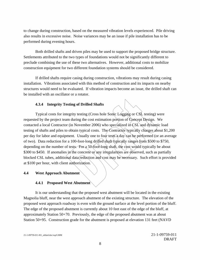
to change during construction, based on the measured vibration levels experienced. Pile driving also results in excessive noise. Noise variances may be an issue if pile installation has to be performed during evening hours.
Both drilled shafts and driven piles may be used to support the proposed bridge structure. Settlements attributed to the two types of foundations would not be significantly different to preclude combining the use of these two alternatives. However, additional costs to mobilize construction equipment for two different foundation systems should be considered.
If drilled shafts require casing during construction, vibrations may result during casing installation. Vibrations associated with this method of construction and its impacts on nearby structures would need to be evaluated. If vibration impacts become an issue, the drilled shaft can be installed with an oscillator or a rotator.
4.3.4 Integrity Testing of Drilled Shafts
Typical costs for integrity testing (Cross hole Sonic Logging or CSL testing) were requested by the project team during the cost estimation portion of Concept Design. We contacted a local Contractor (in November 2006) who specialized in CSL and dynamic load testing of shafts and piles to obtain typical costs. The Contractor typically charges about $1,200 per day for labor and equipment. Usually one to four tests a day can be performed (or an average of two). Data reduction for a 100-foot-long drilled shaft typically ranges from $500 to $750, depending on the number of tests. For a 50-foot-long shaft, the cost would typically be about $300 to $450. If anomalies in the concrete or any irregularities are observed, such as partially blocked CSL tubes, additional data reduction and cost may be necessary. Such effort is provided at $100 per hour, with client authorization.
4.4 West Approach Abutment
4.4.1 Proposed West Abutment
It is our understanding that the proposed west abutment will be located in the existing Magnolia bluff, near the west approach abutment of the existing structure. The elevation of the proposed west approach roadway is even with the ground surface at the level portion of the bluff. The edge of the proposed abutment is currently about 10 feet east of the edge of the bluff, at approximately Station 50+70. Previously, the edge of the proposed abutment was at about Station 50+95. Construction grade for the abutment is proposed at elevation 131 feet (NAVD

21-1-09759-011-R1_edited.doc/wp/LMM 21-1-09759-011 DRAFT
9
88). At Station 50+70, the existing ground surface elevation is around elevation 130 feet; at station 50+95, the ground surface elevation is around elevation 141 feet. We understand that by moving the abutment to the east, less excavation into the bluff will be necessary.
Additional subsurface explorations will be necessary to accurately estimate how much excavation will be necessary. If further explorations indicate that the proposed abutment is located on top of weathered soil or colluvium, excavation of these soils will be necessary before the abutment can be constructed.
Additionally, prior to finalizing the abutment location, the space required to perform drilled shaft construction should be considered. A level bench should be wide enough to accommodate drilled shaft construction equipment.
4.4.2 Existing West Abutment
We recommend that the foundation for the west abutment of the existing bridge structure remain in place. If the foundation is removed, soil behind the existing abutment wall would also have to be removed, which could potentially create an unstable condition.
4.5 Mechanically Stabilized Earth (MSE) Walls for Approach Fill Embankments
We understand that MSE walls are being considered for the approach fill embankments at the eastern end of the project site. MSE walls are one of the most cost-effective alternatives for retaining walls. It has been our experience that MSE walls generally result in savings of 25 to 40 percent in comparison with conventional reinforced concrete retaining walls. Additional savings can be realized by the flexibility of these systems when compared to conventional walls. The cost of an MSE wall is highly dependent on the facing selection, which can vary from one-fourth to one-third of the total wall cost.
There are a number of different types of MSE walls that could be constructed at the project site. Three common types of proprietary MSE walls are Hilfiker Retaining Walls, Keystone Blocks with earth reinforcing geogrids, and geogrid-reinforced earth with geotextile wrapping at the face. The Hilfiker wall uses metallic welded wire mesh to reinforce the soil and retain the backfill. Most walls with non-metallic (geosynthetic) inclusions are non-proprietary systems in that there is a choice of several different types of geosynthetics with similar strengths, combined with a choice of several different facing systems. Connection of the geosynthetic to the facing is critical to the success of the retaining wall.

21-1-09759-011-R1_edited.doc/wp/LMM 21-1-09759-011 DRAFT
10
The base width of MSE walls is typically on the order of 70 percent of the wall height (0.7H).
4.5.1 Facings
A consideration in determining the type of facing is the settlement that is anticipated to occur from the fill placement and construction of the walls. It has been our experience that Keystone blocks generally withstand up to 2 to 3 inches of differential settlement over a distance of about 200 feet without showing distress. For walls with differential settlements greater than 2 to 3 inches, we recommend using a flexible wall system where the facing is applied after the settlement is substantially completed.
4.5.2 Reinforced and Retained Backfill Materials
Backfill within the zone of reinforced soil is generally specified to be a granular fill such as gravel borrow per Section 9-03.14 (1) of the 2006 Standard Specifications for Road, Bridge, and Municipal Construction. For Hilfiker walls, the backfill in the reinforced zone can be angular gravel and quarry spall material. We recommend a maximum particle size of 6 inches. If material smaller than the Hilfiker welded wire mat opening is used, we recommend a hardware cloth (typically a ¼ inch galvanized wire mesh screen) be placed within the facing of the Hilfiker wall to retain the backfill. The use of a hardware cloth should be in accordance with the manufacturer’s recommendations.
4.5.3 Drainage Provisions
The proposed MSE walls would be constructed as fill walls above the surrounding ground surface, the top of the fill would likely be sealed with pavement, and the reinforced and retained fills would be constructed with relatively clean material. However, in sloping ground conditions or in wet weather, groundwater or surface water may be able to periodically build up behind the walls. Therefore, we recommend that a specific drainage layer located on the back side of the reinforced soil zone be included in the design and construction of all MSE walls on the project.
4.6 Removal and Replacement of Approach Fill West of 15th Avenue West
We understand that the existing approach fill embankment west of 15th Avenue West is retained by concrete retaining walls, which will be removed and replaced with MSE walls, as part of this project. The height of this embankment will be approximately 2 to 3 feet higher than the existing

21-1-09759-011-R1_edited.doc/wp/LMM 21-1-09759-011 DRAFT
11
concrete retaining walls. It is our opinion that settlement resulting from the additional wall height will not be significant. However, for long term performance and stability, we recommend that ground improvement be performed to mitigate the liquefaction potential that exists underlying the embankment.
4.7 Temporary Structures
4.7.1 MSE Temporary Ramps
We understand that a MSE wall is proposed for the temporary ramp in the northwest quadrant of the existing BNSF Railway Company (BNSF) railroad and Magnolia Bridge intersection. This temporary ramp would head north and loop southwest to reconnect with the existing bridge (see Figure 1). The initial portion of the ramp structure will have a 6 percent grade, therefore, 100 feet north of the existing bridge structure, the ramp will be 6 feet high. Within the initial 100 feet from the existing bridge structure, the ramp will likely be constructed as an earthen embankment. Beyond 100 feet, we understand that the project team is considering an MSE embankment. Where the temporary ramp structure is within 50 feet of the existing bridge structure and the wall height is greater than 6 feet, we recommend that the ramp structure be an elevated structure, rather than an MSE embankment, to prevent settlement of the existing bridge structure.
4.7.2 Timber Pile-supported Staging
It is our understanding that temporary work platforms will be necessary overwater, in Smith Cove (between proposed Stations 36+00 and 41+00) and at Jacobs Lake. We understand that timber piles are preferred for foundation support, as excavation for and/or placement of mat foundations would be difficult in the water. Additionally, the magnitude of vibrations will be small by driving low capacity timber piles.
Timber piles would be a feasible alternative for temporary staging support constructed over Smith Cove, unless a lot of obstructions are present. Timber piles would be typically 30 to 50 feet long. At Smith Cove, refusal when driving timber piles would probably occur around a depth of about 30 feet below the ground surface (around elevation -15 feet NAVD88). At Jacobs Lake, refusal would likely occur around 50 feet below the ground surface (around elevation -30 feet NAVD88). For estimating purposes, given our knowledge of the existing subsurface conditions in this area and the estimated pile lengths, we recommend that timber piles in these two locations be designed for an allowable load of 30 tons per pile.
21-1-09759-011-R1_edited.doc/wp/LMM 21-1-09759-011 DRAFT
12
Untreated timber piles will be acceptable for temporary construction staging support, as staging will probably be in use for about one year. Degradation of timber piles over one year should be minimal.
4.7.3 Mat Foundation-supported Staging
Mat foundations are proposed for support of temporary construction staging on land. Figure 45, Ultimate Footing Bearing Resistance Versus Effective Footing Width provides our recommendations for mat foundation design.
Based on the existing borings, loose to medium dense fill would likely be encountered in the upper 7 to 10 feet below the existing ground surface. We assumed that the footings would be placed in the existing fill layer, within 6 to 12 inches of the ground surface. This figure contain ultimate bearing resistances for service and strength limit state design, with footing sizes ranging from 2 to 5 feet. Compressible fine-grained soils are generally present below the upper fill soils. If the mat foundation widths need to be larger than 5 feet, we will need to re-evaluate the settlements. In general, the borings indicate that the fill material is predominantly granular, therefore, most of the settlement would occur during the loading period or shortly thereafter.
Based on field mud sill load tests (plate bearing load tests) that we performed on similar loose to medium dense fill soils at previous project sites, we recommend that the ultimate bearing resistances for the 1-inch service limit state (in Figure 45) be considered in the evaluation of the falsework support during construction.
4.8 Fill Placement at Jacobs Lake
We understand that Jacobs Lake (see Figure 1 for location) will be filled at some point in the future, likely during or after this bridge replacement project. The existing man-made lake is approximately 10 to 15 feet deep, 200 feet wide, and 400 feet long. The application of this fill load would likely result in significant settlement of the underlying Estuarine deposits. Downdrag forces attributed to this settlement would subsequently be imposed on the existing and new foundations in this area.
When considering downdrag forces resulting from settlement due to fill loading (i.e., of Jacobs Lake), we recommend an FS of 1.3 (resistance factor of 0.75) be considered. For Concept Design, it is our opinion that downdrag forces resulting from settlement due to the fill

21-1-09759-011-R1_edited.doc/wp/LMM 21-1-09759-011 DRAFT
13
loads will be similar to downdrag forces resulting from seismically-induced settlement. During TS&L design, we will reevaluate this situation.
4.9 Potential Contamination Issues
Contaminated soil with high polychlorinated biphenyl (PCB) concentrations (greater than 50 milligrams per kilogram (mg/kg) is banned from general landfill disposal. If such soils are encountered during excavation, the cost of disposal by incineration will likely be between $1,000 and $1,500 per cubic yard. This cost estimate includes field work costs to segregate soils. Product from wells within the former tank farm (see Figure 1) contained an average PCB concentration of 50 milligrams per liter (mg/L), which indicates that soil with PCB concentrations above 50 mg/kg is likely present in some areas. For a conservative estimate, we recommend assuming that approximately 5 percent of the soils will be contaminated from the proposed construction excavations.
5.0 LIMITATIONS
This report was prepared for the exclusive use of Seattle Department of Transportation (SDOT), HNTB, and the project team for Task 5, Concept Design, of the Magnolia Bridge Replacement Project. This report should not be considered a warranty of subsurface conditions, such as those interpreted from previous exploration logs and discussions of subsurface conditions included in this report.
The analyses, conclusions, and recommendations contained in this report are based on site conditions as they presently exist. We assume that the existing subsurface explorations performed at this site are representative of the subsurface conditions at the project site; i.e., the subsurface conditions everywhere are not significantly different from those disclosed by the explorations. The content of this report is not intended for final design or construction; additional field explorations and analyses will be required during the TS&L design phase.
Within the limitations of the scope, schedule and budget, the analyses, conclusions, and recommendations presented in this report were prepared in accordance with generally accepted professional geotechnical engineering principles and practice in this area at the time this report was prepared. We make no other warranty, either express or implied.

21-1-09759-011-R1_edited.doc/wp/LMM 21-1-09759-011 DRAFT
14
The scope of our services for Task 5 did not include any environmental assessment or evaluation of hazardous or toxic materials in the soil, surface water, groundwater, or air at the subject site. Shannon & Wilson, Inc., has qualified personnel to assist you with these services should they be necessary.
Shannon & Wilson, Inc. has prepared and included as Appendix, “Important Information About Your Geotechnical Report,” to assist you and others in understanding the use and limitations of our reports.
SHANNON & WILSON, INC. Laureen M. McKenna, P.E. Senior Engineer Ming-Jiun (Jim) Wu, P.E., Ph.D. Senior Vice President LMM:JW/lmm

TABLEGROUND IMPROVEMENT RECOMMENDATIONS(1)
StoneColumns
Compaction Grouting
West of Station 35+00(around existing Bent 45) 10 to 30
Between approximate stations 35+00 and 19+50 50 50 40 30
East of approximatly station 19+50 to 15th Ave West 30 30 40 30
East of 15th Ave West 30 30 15 10
Notes:
Recommended Lateral Extent of Improvement(4)
(feet)Estimated Depth of Improvement
(feet)
Approximate Depth of Liquefiable Soils(3)
(feet)Location(2)
4. The recommended lateral extent of improvement should be considered a uniform distance measured from all sides of the foundation cap, drilled shafts, or approach fill embankment.
1. The recommendations and conclusions provided in this table are based on the existing subsurface information gathered for the Geotechnical Data Report, which was prepared in 2003, and the two additional subsurface explorations performed in 2005. Subsurface explorations were not performed for this phase of work. Additional explorations and analyses will be necessary in the TS&L design phase to better define the depth and extent of ground improvement.
Ground Improvement not recommended;structure should be designed to withstand equivalent lateral
spread force
2. Locations are based on proposed alignment stationiong for the concrete box and steel girder option; stationing is presented on Figure 1, Site Plan and Exploration.
3. Depth of liquefiable soils were estimated based on the limited liquefaction analyses we have performed for the project to this date. Additional liquefaction analyses will be necessary in the TS&L design phase.
Ground improvement recommendations.xls/ lmm- 11/29/2006 21-1-09759-011

Northwest Harvest
National GuardArmory
Terminal 90Terminal 91
Port ofSeattle
SMITH COVE SMITH COVE SMITH COVE
14-1
14-2
1647-2
15-1 2-32-2
2-42-5
13-1813-19
13-713-6
3352-2 3352-13352-3CP_108B
CP_103BCP_111
13-313-2
3-33-5
14-3
EB-2
A
A'
21-1-09759-011
SITE AND EXPLORATION PLANCONCEPT DESIGN
FIG. 1
Magnolia Bridge ReplacementSeattle, Washington
November 2006
0 200 400
Scale in Feet
SHANNON & WILSON, INC.
LEGENDCurrent Shannon & Wilson, Inc.Boring Designation andApproximate Location
Previous Boring Designationand Approximate Location
Smith Cove and Jacobs Lake(water)
Generalized Subsurface Profile(See Figure 2)
Figure adapted from electronic filesprovided by HTNB, received 11-27-06.The generalized subsurface profileshown on this plan was prepared forRehabilitation Alternative in October2005. The profile has not beenupdated to follow the current proposedalignment.
Boring locations and elevations areapproximate.
NOTES
1.
2.
A
Bent 65Location ofExploratory Test Pit
Bent 45Location ofExploratory Test Pit
Jacobs Lake
Existing15th Ave NWOverpass
File
nam
e: J
:\211
\097
59-0
11\2
1-1-
0975
9-01
1 S
ite P
lan.
dwg
L
ayou
t: Fi
g 1
D
ate:
11-
28-2
006
L
ogin
: SAC
PROPOSED23RD AVE W
ONRAMP
PROPOSED23RD AVE WOFFRAMP
PROPOSEDTEMPORARYRAMP STRUCTURE
21-1-09759-011
GENERALIZED SUBSURFACE PROFILECONCEPT DESIGN
FIG. 2
Magnolia Bridge ReplacementSeattle, Washington
November 2006
SHANNON & WILSON, INC.
01-31-73
73/6"
11
14-1(Proj. 150' S.E.)
LEGEND
Boring DesignationProjected Distance and Direction to Alignment
Standard Penetration Test (SPT) Blows/Foot
Standard Penetration Test (SPT) Blows/Inches Driven
Grab Sample
Shelby Tube Sample
Osterberg Tube Sample
Nonstandard Penetration Test, Blow Count Convertedto an Approximate SPT in Blows/Foot
Nonstandard Penetration Test, Blow Count Convertedto an Approximate SPT in Blows/Inches Driven
Porter Penetration Test (PPT), Blows/6 Inches(every other PPT shown)
Groundwater Level Observed During Drilling
Groundwater Level and Date Recorded
Approximate Geologic Contact
Glacially Overridden Soil Units Below Line
Bottom of BoringDate Completed
??
NOTES
This subsurface profile is generalized from materials observed in soilborings. Variations may exist between profile and actual conditions.Contact lines are dashed where questionable.
Figure adapted from electronic files provided by HNTB, received 5-19-03.The subsurface profile was prepared for Rehabilitation Alternative inOctober 2005. The profile has not been updated to follow the currentproposed alignment.
Datum: NAVD 88
1.
2.
3.
6-15
-72
11
73/6"
22
O
G
Vertical Exaggeration = 5X
0 40 80
Vertical Scale in Feet
0 200 400
Horizontal Scale in Feet
GEOLOGIC UNITS
Qvat
Qva
Qpnl
Qpnf
Qvgl
Qvd
FILL: Fill placed by humans, both engineered and nonengineeredVarious materials, including debris; cobbles and boulders common; commonly dense or stiff if engineered, butvery loose to dense or very soft to stiff if nonengineered.
COLLUVIUM: Hillside slope accumulations due to gravity emplacementDisturbed, heterogeneous mixture of several soils types, including organic debris; loose or soft.
LANDSLIDE DEPOSITS: Deposits of landslides, normally at and adjacent to the toe of slopesDisturbed, heterogeneous mixture of several soil types; loose or soft, with random dense or hard pockets.
ESTUARINE DEPOSITS: Estuary deposits of intertidal zones associated with rivers and streams located alongthe present and former Puget Sound shorelineClayey Silt, silty Clay, Silt, and fine Sand; very soft to very stiff or very loose to medium dense.
BEACH DEPOSITS: Deposits along present and former shorelines of Puget Sound and tributary river mouthsSilty Sand, sandy Gravel, Sand, scattered fine Gravel, organic and shell debris; loose to dense.
REWORKED GLACIAL DEPOSITS: Glacially deposited soils that have been reworked by fluvial or wave actionHeterogenous mixture of several soil types; lies on top of glacially overridden soils; loose to dense.
RECESSIONAL OUTWASH DEPOSITS: Glaciofluvial sediment deposited as glacial ice retreatedClean to silty Sand, gravelly Sand, sandy Gravel; cobbles and boulders common; loose to very dense.
ABLATION TILL: Heterogenous soils deposited during the wasting of glacial ice; geneerally not reworkedGravelly silty Sand, silty gravelly Sand, with some clay; cobble sna dboulders common; loose to very dense or softto hard.
TILL: Lodgment till laid down along the base of the glacial iceGravelly silty Sand, silty gravelly Sand ("hardpan"); cobbles and boulders common; very dense.
TILL-LIKE DEPOSITS (DIAMICT): Glacial deposit intermediate between till and outwash; subglacially reworkedSilty gravelly Sand, silty Sand, sandy Gravel; highly variable over short distances; cobbles and boulders common;dense to very dense.
ADVANCE OUTWASH: Glaciofluvial sediment deposited as the glacial ice advanced through the Puget LowlandClean to silty Sand, gravelly Sand, sandy Gravel; dense to very dense.
GLACIOLACUSTRINE DEPOSITS: Fined-grained glacial flour deposited in proglacial lake in Puget LowlandSilty clay, Clayey Silt, with interbeds of Silt and fine Sand; locally laminated; scattered organic fragments near base;hard or dense to very dense.
Qvro
Qvt
Hrw
He
Hb
Hls
Hf
FLUVIAL DEPOSITS: Alluvial deposits of rivers and creeksClean to silty Sand, gravelly Sand, sandy Gravel; very dense.
LACUSTRINE DEPOSITS: Fine-grained lake deposits in depressions, large and smallFine sandy Silt, silty fine Sand, clayey Silt; scattered to abundant fine organics; dense to very dense or very stiff to hard.
MUDFLOW DEPOSITS: Distal deposits of mass movements such as landslides or laharsStraified or irregular bodies of a heterogeneous mixture of Gravel, Sand, Silt, and Clay; pumice, obsidian and ashcommon; rare organics (charcoal); very stiff to hard or very dense.
OUTWASH: Glaciofluvial sediment deposited as the glacial ice advanced through the Puget LowlandClean to silty Sand, gravelly Sand, sandy Gravel; very dense.
GLACIOLACUSTRINE DEPOSITS: Fine-grained glacial flour deposited in proglacial lake in Puget LowlandSilty Clay, clayey Silt, with interbeds of Silt and fine Sand; very stiff to hard or very dense.
TILL: Lodgment till laid down along the base of the glacial iceGravelly silty Sand, silty gravelly Sand ("hardpan"); cobbles and boulders common; very dense.
Hc
HOLOCENE DEPOSITS
QUATERNARY VASHON DEPOSITS
Qpgo
QUATERNARY PRE-VASHON DEPOSITS
The description of each geologic unit includes only general informationregarding the environment of deposition and basic soil characteristics.
NOTE
Qpgl
Qpnm
? ?
Qpgt
01-31-73
73/6"
11
14-1(Proj. 150' S.E.)
LEGEND
Boring DesignationProjected Distance and Direction to Alignment
Standard Penetration Test (SPT) Blows/Foot
Standard Penetration Test (SPT) Blows/Inches Driven
Grab Sample
Shelby Tube Sample
Osterberg Tube Sample
Nonstandard Penetration Test, Blow Count Convertedto an Approximate SPT in Blows/Foot
Nonstandard Penetration Test, Blow Count Convertedto an Approximate SPT in Blows/Inches Driven
Porter Penetration Test (PPT), Blows/6 Inches(every other PPT shown)
Groundwater Level Observed During Drilling
Groundwater Level and Date Recorded
Approximate Geologic Contact
Glacially Overridden Soil Units Below Line
Bottom of BoringDate Completed
?? 6-15
-72
11
73/6"
22
O
G
Vertical Exaggeration = 5X
0 40 80
Vertical Scale in Feet
0 200 400
Horizontal Scale in Feet
GEOLOGIC UNITS
Qvat
Qva
Qpnl
Qpnf
Qvgl
Qvd
FILL: Fill placed by humans, both engineered and nonengineeredVarious materials, including debris; cobbles and boulders common; commonly dense or stiff if engineered, butvery loose to dense or very soft to stiff if nonengineered.
COLLUVIUM: Hillside slope accumulations due to gravity emplacementDisturbed, heterogeneous mixture of several soils types, including organic debris; loose or soft.
LANDSLIDE DEPOSITS: Deposits of landslides, normally at and adjacent to the toe of slopesDisturbed, heterogeneous mixture of several soil types; loose or soft, with random dense or hard pockets.
ESTUARINE DEPOSITS: Estuary deposits of intertidal zones associated with rivers and streams located alongthe present and former Puget Sound shorelineClayey Silt, silty Clay, Silt, and fine Sand; very soft to very stiff or very loose to medium dense.
BEACH DEPOSITS: Deposits along present and former shorelines of Puget Sound and tributary river mouthsSilty Sand, sandy Gravel, Sand, scattered fine Gravel, organic and shell debris; loose to dense.
REWORKED GLACIAL DEPOSITS: Glacially deposited soils that have been reworked by fluvial or wave actionHeterogenous mixture of several soil types; lies on top of glacially overridden soils; loose to dense.
RECESSIONAL OUTWASH DEPOSITS: Glaciofluvial sediment deposited as glacial ice retreatedClean to silty Sand, gravelly Sand, sandy Gravel; cobbles and boulders common; loose to very dense.
ABLATION TILL: Heterogenous soils deposited during the wasting of glacial ice; geneerally not reworkedGravelly silty Sand, silty gravelly Sand, with some clay; cobble sna dboulders common; loose to very dense or softto hard.
TILL: Lodgment till laid down along the base of the glacial iceGravelly silty Sand, silty gravelly Sand ("hardpan"); cobbles and boulders common; very dense.
TILL-LIKE DEPOSITS (DIAMICT): Glacial deposit intermediate between till and outwash; subglacially reworkedSilty gravelly Sand, silty Sand, sandy Gravel; highly variable over short distances; cobbles and boulders common;dense to very dense.
ADVANCE OUTWASH: Glaciofluvial sediment deposited as the glacial ice advanced through the Puget LowlandClean to silty Sand, gravelly Sand, sandy Gravel; dense to very dense.
GLACIOLACUSTRINE DEPOSITS: Fined-grained glacial flour deposited in proglacial lake in Puget LowlandSilty clay, Clayey Silt, with interbeds of Silt and fine Sand; locally laminated; scattered organic fragments near base;hard or dense to very dense.
Qvro
Qvt
Hrw
He
Hb
Hls
Hf
FLUVIAL DEPOSITS: Alluvial deposits of rivers and creeksClean to silty Sand, gravelly Sand, sandy Gravel; very dense.
LACUSTRINE DEPOSITS: Fine-grained lake deposits in depressions, large and smallFine sandy Silt, silty fine Sand, clayey Silt; scattered to abundant fine organics; dense to very dense or very stiff to hard.
MUDFLOW DEPOSITS: Distal deposits of mass movements such as landslides or laharsStraified or irregular bodies of a heterogeneous mixture of Gravel, Sand, Silt, and Clay; pumice, obsidian and ashcommon; rare organics (charcoal); very stiff to hard or very dense.
OUTWASH: Glaciofluvial sediment deposited as the glacial ice advanced through the Puget LowlandClean to silty Sand, gravelly Sand, sandy Gravel; very dense.
GLACIOLACUSTRINE DEPOSITS: Fine-grained glacial flour deposited in proglacial lake in Puget LowlandSilty Clay, clayey Silt, with interbeds of Silt and fine Sand; very stiff to hard or very dense.
TILL: Lodgment till laid down along the base of the glacial iceGravelly silty Sand, silty gravelly Sand ("hardpan"); cobbles and boulders common; very dense.
Hc
HOLOCENE DEPOSITS
QUATERNARY VASHON DEPOSITS
Qpgo
QUATERNARY PRE-VASHON DEPOSITS
The description of each geologic unit includes only general informationregarding the environment of deposition and basic soil characteristics.
NOTE
Qpgl
Qpnm
? ?
Qpgt
21-1-09759-011
GENERALIZED SUBSURFACE PROFILECONCEPT DESIGN
FIG. 2
Magnolia Bridge ReplacementSeattle, Washington
November 2006
SHANNON & WILSON, INC.
NOTES
This subsurface profile is generalized from materials observed in soilborings. Variations may exist between profile and actual conditions.Contact lines are dashed where questionable.
Figure adapted from electronic files provided by HNTB, received 5-19-03.The subsurface profile was prepared for Rehabilitation Alternative inOctober 2005. The profile has not been updated to follow the currentproposed alignment.
Datum: NAVD 88
1.
2.
3.
File
nam
e: J
:\211
\097
59-0
11\2
1-1-
0975
9-01
1 P
rofil
e.dw
g
Lay
out:
Fig
2
Dat
e: 1
1-28
-200
6
Log
in: S
ACFi
lena
me:
J:\2
11\0
9759
-011
\21-
1-09
759-
011
Pro
file.
dwg
L
ayou
t: Fi
g 2
D
ate:
11-
28-2
006
L
ogin
: SAC

11/28/2006-Axial Capacity_Bents 63 to 74.xls,AC Plot-lmm
FIG. 3
UPDATED ESTIMATED STATICALLOWABLE AXIAL CAPACITIES
BENTS 63 TO 74 (DRILLED SHAFTS)
Magnolia Bridge ReplacementSeattle, Washington
August 2006 21-1-09759-008
-50
-40
-30
-20
-10
0
10
200 500 1000 1500 2000 2500 3000 3500 4000
ESTIMATED STATIC ALLOWABLE AXIAL CAPACITY (tons)
SHA
FT B
ASE
ELE
VATI
ON
(fee
t)
4-ft-diam. drilled shaft
6-ft-diam. drilled shaft
8-ft-diam. drilled shaft
10-ft-diam. drilled shaft
SHANNON & WILSON, INC.Geotechnical and Environmental Consultants
NOTES
1.
2.
3.
4.
Static allowable axial capacities were determined by summing the allowable skin friction and allowable end bearing. For drilled shafts the allowable end bearing was equal to the mobilized end bearing. This mobilized end bearing was limited to 50% of the ultimate end bearing. A factor of safety of 2.0 was applied to the estimated ultimate skin friction and ultimate end bearing, where applicable, to obtain allowable values.
Calculations assume loading conditions for a single shaft. Shaft group effects are not considered.
Full end bearing is not achieved until the shaft penetrates at least 3 to 5 feet into the bearing layer.
Estimated capacities assume that if casing is used, it will be removedafter the shaft installation. If, however, the casing is left in place, grouting should be used to fill all potential voids around the casing and the estimated capacities given above should be re-evaluated.
Fill
Beach deposits(Improved)
Glacial deposits
6'
42'
GENERALIZED SUBSURFACECONDITIONS
(See Subsurface Profile)Ground Surface Elev.~16 ft
Depth (ft)
21'
Estuarine deposits
66'

11/28/2006-Axial Capacity_Bents 63 to 74.xls,AC Plot (2)-lmm
FIG. 4
UPDATED ESTIMATED STATICALLOWABLE AXIAL CAPACITIESBENTS 63 TO 74 (STEEL PILES)
Magnolia Bridge ReplacementSeattle, Washington
August 2006 21-1-09759-008
-80
-70
-60
-50
-40
-30
-20
-10
0
10
200 100 200 300 400 500 600 700
ESTIMATED STATIC ALLOWABLE AXIAL CAPACITY (tons)
PILE
TIP
ELE
VATI
ON
(fee
t)
24-in-diam. opened-ended pipe pile
36-in-diam. opened-ended pipe pile
SHANNON & WILSON, INC.Geotechnical and Environmental Consultants
NOTES
1.
2.
3.
Static allowable axial capacities were determined by summing the allowable skin friction and allowable end bearing. A factor of safety of 2.0 was applied to the estimated ultimate skin friction and ultimate end bearing to obtain allowable values.
Calculations assume loading conditions for a single pile. PIlegroup effects are not considered.
A wall thickness of 3/4 inches was assumed.
Fill
Beach deposits(Improved)
Glacial deposits
6'
42'
GENERALIZED SUBSURFACECONDITIONS
(See Subsurface Profile)Ground Surface Elev.~16 ft
Depth (ft)
21'
Estuarine deposits
96'

11/28/2006-Axial Capacity_Bents 63 to 74.xls,Uplift-lmm
FIG. 5
UPDATED ESTIMATED STATICULTIMATE UPLIFT CAPACITIES
BENTS 63 TO 74
Magnolia Bridge ReplacementSeattle, Washington
August 2006 21-1-09759-008
-80
-70
-60
-50
-40
-30
-20
-10
0
10
200 500 1000 1500 2000 2500 3000 3500 4000
ESTIMATED STATIC ULTIMATE UPLIFT CAPACITY (tons)
PILE
TIP
/ SH
AFT
BA
SE E
LEVA
TIO
N (f
eet)
4-ft-diam. drilled shaft
6-ft-diam. drilled shaft
8-ft-diam. drilled shaft
10-ft-diam. drilled shaft
24-in-diam. open-ended pipe pile
36-in-diam. open-ended pipe pile
SHANNON & WILSON, INC.Geotechnical and Environmental Consultants
NOTES
1.
2.
To obtain allowable uplift resistance, we recommend that an appropriate FS be applied to the ultimate uplift values. The recommended FS values are 3.0 for long-term loading and 1.5 for transient loading.
Calculations assume loading conditions for a single pile/shaft. Pile/shaft group effects are not considered.
Fill
Beach deposits(Improved)
Glacial deposits
6'
42'
GENERALIZED SUBSURFACECONDITIONS
(See Subsurface Profile)Ground Surface Elev.~16 ft
21'
Estuarine deposits
Depth (ft)
96'
11/28/2006-Axial Capacity_Bents 47 to 62.xls,AC Plot-lmm
FIG. 6
UPDATED ESTIMATED STATICALLOWABLE AXIAL CAPACITIES
BENTS 47 TO 62 (DRILLED SHAFTS)
Magnolia Bridge ReplacementSeattle, Washington
August 2006 21-1-09759-008
-50
-40
-30
-20
-10
0
10
200 500 1000 1500 2000 2500 3000 3500 4000
ESTIMATED STATIC ALLOWABLE AXIAL CAPACITY (tons)
SHA
FT B
ASE
ELE
VATI
ON
(fee
t)
4-ft-diam. drilled shaft
6-ft-diam. drilled shaft
8-ft-diam. drilled shaft
10-ft-diam. drilled shaft
SHANNON & WILSON, INC.Geotechnical and Environmental Consultants
NOTES
1.
2.
3.
4.
Static allowable axial capacities were determined by summing the allowable skin friction and allowable end bearing. For drilled shafts the allowable end bearing was equal to the mobilized end bearing. This mobilized end bearing was limited to 50% of the ultimate end bearing. A factor of safety of 2.0 was applied to the estimated ultimate skin friction and ultimate end bearing, where applicable, to obtain allowable values.
Calculations assume loading conditions for a single shaft. Shaft group effects are not considered.
Full end bearing is not achieved until the shaft penetrates at least 3 to 5 feet into the bearing layer.
Estimated capacities assume that if casing is used, it will be removedafter the shaft installation. If, however, the casing is left in place, grouting should be used to fill all potential voids around the casing and the estimated capacities given above should be re-evaluated.
Fill
Beach deposits(Improved)
Glacial deposits
12'
50'
GENERALIZED SUBSURFACECONDITIONS
(See Subsurface Profile)Ground Surface Elev.~16 ft
Depth (ft)
66'

11/28/2006-Axial Capacity_Bents 47 to 62.xls,AC Plot (2)-lmm
FIG. 7
UPDATED ESTIMATED STATICALLOWABLE AXIAL CAPACITIESBENTS 47 TO 62 (STEEL PILES)
Magnolia Bridge ReplacementSeattle, Washington
August 2006 21-1-09759-008
-80
-70
-60
-50
-40
-30
-20
-10
0
10
200 100 200 300 400 500 600 700 800
ESTIMATED STATIC ALLOWABLE AXIAL CAPACITY (tons)
PILE
TIP
ELE
VATI
ON
(fee
t)
24-in-diam. open-ended pipe pile
36-in-diam. open-ended pipe pile
SHANNON & WILSON, INC.Geotechnical and Environmental Consultants
NOTES
1.
2.
3.
Static allowable axial capacities were determined by summing the allowable skin friction and allowable end bearing. A factor of safety of 2.0 was applied to the estimated ultimate skin friction and ultimate end bearing to obtain allowable values.
Calculations assume loading conditions for a single pile. Pile group effects are not considered.
A wall thickness of 3/4 inches was assumed.
Fill
Beach deposits(Improved)
Glacial deposits
12'
50'
GENERALIZED SUBSURFACECONDITIONS
(See Subsurface Profile)Ground Surface Elev.~16 ft
Depth (ft)
96'
11/28/2006-Axial Capacity_Bents 47 to 62.xls,Uplift-lmm
FIG. 8
UPDATED ESTIMATED STATICULTIMATE UPLIFT CAPACITIES
BENTS 47 TO 62
Magnolia Bridge ReplacementSeattle, Washington
August 2006 21-1-09759-008
-80
-70
-60
-50
-40
-30
-20
-10
0
10
200 500 1000 1500 2000 2500 3000 3500 4000
ESTIMATED STATIC ULTIMATE UPLIFT CAPACITY (tons)
PILE
TIP
/ SH
AFT
BA
SE E
LEVA
TIO
N (f
eet)
4-ft-diam. drilled shaft
6-ft-diam. drilled shaft
8-ft-diam. drilled shaft
10-ft-diam. drilled shaft
24-in-diam. open-ended pipe pile
36-in-diam. open-ended pipe pile
SHANNON & WILSON, INC.Geotechnical and Environmental Consultants
NOTES
1.
2.
To obtain allowable uplift resistance, we recommend that an appropriate FS be applied to the ultimate uplift values. The recommended FS values are 3.0 for long-term loading and 1.5 for transient loading.
Calculations assume loading conditions for a single pile/shaft. Pile/shaft group effects are not considered.
Fill
Beach deposits(Improved)
Glacial deposits
12'
50'
GENERALIZED SUBSURFACECONDITIONS
(See Subsurface Profile)Ground Surface Elev.~16 ft
Depth (ft)
96'

11/28/2006-Axial Capacity_Bents 26 to 46.xls,AC Plot-lmm
FIG. 9
UPDATED ESTIMATED STATICALLOWABLE AXIAL CAPACITIES
BENTS 26 TO 46 (DRILLED SHAFTS)
Magnolia Bridge ReplacementSeattle, Washington
August 2006 21-1-09759-008
-110
-100
-90
-80
-70
-60
-50
-40
-30
-20
-10
0
10
200 500 1000 1500 2000 2500 3000 3500 4000
ESTIMATED STATIC ALLOWABLE AXIAL CAPACITY (tons)
SHA
FT B
ASE
ELE
VATI
ON
(fee
t)
4-ft-diam. drilled shaft
6-ft-diam. drilled shaft
8-ft-diam. drilled shaft
10-ft-diam. drilled shaft
SHANNON & WILSON, INC.Geotechnical and Environmental Consultants
NOTES
1.
2.
3.
4.
Static allowable axial capacities were determined by summing the allowable skin friction and allowable end bearing. For drilled shafts the allowable end bearing was equal to the mobilized end bearing. This mobilized end bearing was limited to 50% of the ultimate end bearing. A factor of safety of 2.0 was applied to the estimated ultimate skin friction and ultimate end bearing, where applicable, to obtain allowable values.
Calculations assume loading conditions for a single shaft. Shaft group effects are not considered.
Full end bearing is not achieved until the shaft penetrates at least 3 to 5 feet into the bearing layer.
Estimated capacities assume that if casing is used, it will be removedafter the shaft installation. If, however, the casing is left in place, grouting should be used to fill all potential voids around the casing and the estimated capacities given above should be re-evaluated.
Fill
Estuarine deposits
Recessional Outwash
12'
100'
GENERALIZED SUBSURFACECONDITIONS
(See Subsurface Profile)Ground Surface Elev.~16 ft
65'
Beach deposits(Improved)
Glacial deposits110'
Depth (ft)
126'
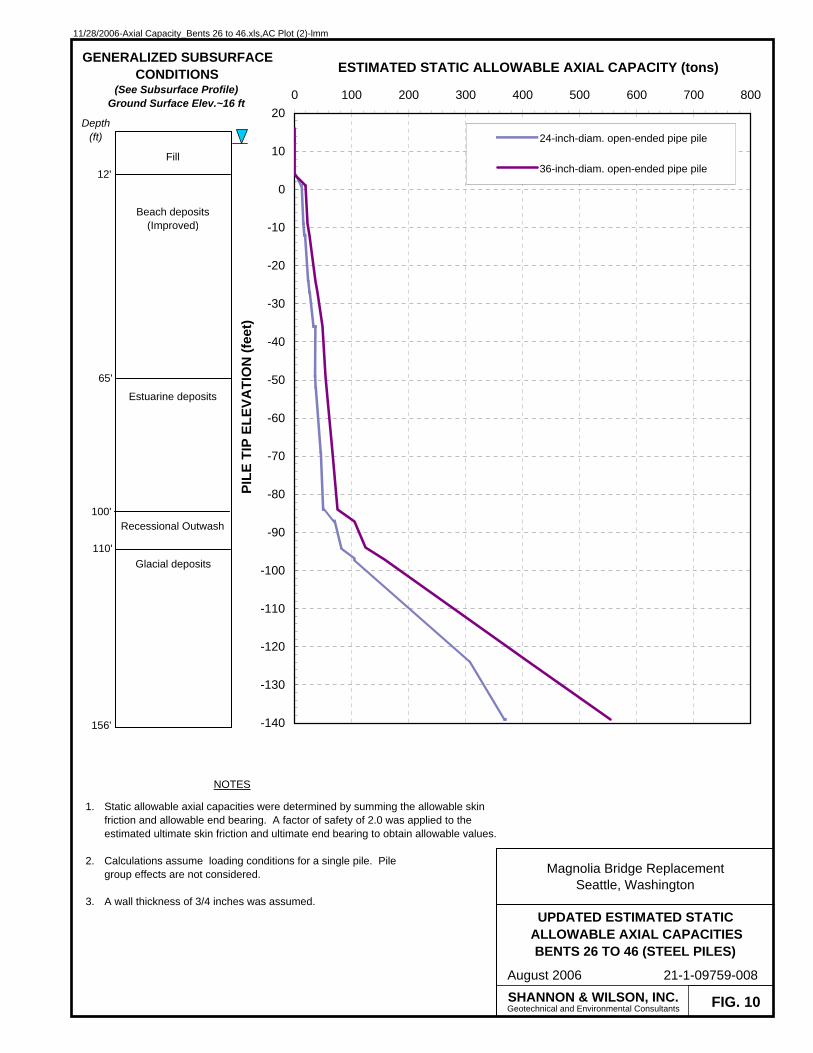
11/28/2006-Axial Capacity_Bents 26 to 46.xls,AC Plot (2)-lmm
FIG. 10
UPDATED ESTIMATED STATICALLOWABLE AXIAL CAPACITIESBENTS 26 TO 46 (STEEL PILES)
Magnolia Bridge ReplacementSeattle, Washington
August 2006 21-1-09759-008
-140
-130
-120
-110
-100
-90
-80
-70
-60
-50
-40
-30
-20
-10
0
10
200 100 200 300 400 500 600 700 800
ESTIMATED STATIC ALLOWABLE AXIAL CAPACITY (tons)
PILE
TIP
ELE
VATI
ON
(fee
t)
24-inch-diam. open-ended pipe pile
36-inch-diam. open-ended pipe pile
SHANNON & WILSON, INC.Geotechnical and Environmental Consultants
NOTES
1.
2.
3.
Static allowable axial capacities were determined by summing the allowable skin friction and allowable end bearing. A factor of safety of 2.0 was applied to the estimated ultimate skin friction and ultimate end bearing to obtain allowable values.
Calculations assume loading conditions for a single pile. Pile group effects are not considered.
A wall thickness of 3/4 inches was assumed.
Fill
Estuarine deposits
Recessional Outwash
12'
100'
GENERALIZED SUBSURFACECONDITIONS
(See Subsurface Profile)Ground Surface Elev.~16 ft
65'
Beach deposits(Improved)
Glacial deposits110'
Depth (ft)
156'

11/28/2006-Axial Capacity_Bents 26 to 46.xls,Uplift-lmm
FIG. 11
UPDATED ESTIMATED STATICULTIMATE UPLIFT CAPACITIES
BENTS 26 TO 46
Magnolia Bridge ReplacementSeattle, Washington
August 2006 21-1-09759-008
-140
-130
-120
-110
-100
-90
-80
-70
-60
-50
-40
-30
-20
-10
0
10
200 500 1000 1500 2000 2500 3000 3500 4000
ESTIMATED STATIC ULTIMATE UPLIFT CAPACITY (tons)
PILE
TIP
/ SH
AFT
BA
SE E
LEVA
TIO
N (f
eet)
4-ft-diam. drilled shaft
6-ft-diam. drilled shaft
8-ft-diam. drilled shaft
10-ft-diam. drilled shaft
24-inch-diam. open-ended pipe pile
36-inch-diam. open-ended pipe pile
SHANNON & WILSON, INC.Geotechnical and Environmental Consultants
NOTES
1.
2.
To obtain allowable uplift resistance, we recommend that an appropriate FS be applied to the ultimate uplift values. The recommended FS values are 3.0 for long-term loading and 1.5 for transient loading.
Calculations assume loading conditions for a single pile/shaft. Pile/shaft group effects are not considered.
Fill
Estuarine deposits
Recessional Outwash
12'
100'
GENERALIZED SUBSURFACECONDITIONS
(See Subsurface Profile)Ground Surface Elev.~16 ft
65'
Beach deposits(Improved)
Glacial deposits110'
Depth (ft)
156'

11/28/2006-Axial Capacity_Bents 18 to 25.xls,AC Plot-lmm
FIG. 12
UPDATED ESTIMATED STATICALLOWABLE AXIAL CAPACITIES
BENTS 18 TO 25 (DRILLED SHAFTS)
Magnolia Bridge ReplacementSeattle, Washington
August 2006 21-1-09759-008
-110
-100
-90
-80
-70
-60
-50
-40
-30
-20
-10
0
10
200 500 1000 1500 2000 2500 3000 3500 4000
ESTIMATED STATIC ALLOWABLE AXIAL CAPACITY (tons)
SHA
FT B
ASE
ELE
VATI
ON
(fee
t)
4-ft-diam. drilled shaft
6-ft-diam. drilled shaft
8-ft-diam. drilled shaft
10-ft-diam. drilled shaft
SHANNON & WILSON, INC.Geotechnical and Environmental Consultants
NOTES
1.
2.
3.
4.
Static allowable axial capacities were determined by summing the allowable skin friction and allowable end bearing. For drilled shafts the allowable end bearing was equal to the mobilized end bearing. This mobilized end bearing was limited to 50% of the ultimate end bearing. A factor of safety of 2.0 was applied to the estimated ultimate skin friction and ultimate end bearing, where applicable, to obtain allowable values.
Calculations assume loading conditions for a single shaft. Shaft group effects are not considered.
Full end bearing is not achieved until the shaft penetrates at least 3 to 5 feet into the bearing layer.
Estimated capacities assume that if casing is used, it will be removedafter the shaft installation. If, however, the casing is left in place, grouting should be used to fill all potential voids around the casing and the estimated capacities given above should be re-evaluated.
Fill
Estuarine deposits
Estuarine deposits
11'
73'
GENERALIZED SUBSURFACECONDITIONS
(See Subsurface Profile)Ground Surface Elev.~16 ft
35'
Beach deposits(Improved)
Glacial deposits
110'
Beach deposits(Improved)
40'
Recessional Outwash102'
Depth (ft)
126'

11/28/2006-Axial Capacity_Bents 18 to 25.xls,AC Plot (2)-lmm
FIG. 13
UPDATED ESTIMATED STATICALLOWABLE AXIAL CAPACITIESBENTS 18 TO 25 (STEEL PILES)
Magnolia Bridge ReplacementSeattle, Washington
August 2006 21-1-09759-008
-140
-130
-120
-110
-100
-90
-80
-70
-60
-50
-40
-30
-20
-10
0
10
200 100 200 300 400 500 600 700 800
ESTIMATED STATIC ALLOWABLE AXIAL CAPACITY (tons)
PILE
TIP
ELE
VATI
ON
(fee
t)
24-inch-diam. open-ended pipe pile
36-inch-diam. open-ended pipe pile
SHANNON & WILSON, INC.Geotechnical and Environmental Consultants
NOTES
1.
2.
3.
Static allowable axial capacities were determined by summing the allowable skin friction and allowable end bearing. A factor of safety of 2.0 was applied to the estimated ultimate skin friction and ultimate end bearing to obtain allowable values.
Calculations assume loading conditions for a single pile. Pilegroup effects are not considered.
A wall thickness of 3/4 inches was assumed.
Fill
Estuarine deposits
Estuarine deposits
11'
73'
GENERALIZED SUBSURFACECONDITIONS
(See Subsurface Profile)Ground Surface Elev.~16 ft
35'
Beach deposits(Improved)
Glacial deposits110'
Beach deposits(Improved)
40'
Recessional Outwash102'
Depth (ft)
156'

11/28/2006-Axial Capacity_Bents 18 to 25.xls,Uplift-lmm
FIG. 14
UPDATED ESTIMATED STATICULTIMATE UPLIFT CAPACITIES
BENTS 18 TO 25
Magnolia Bridge ReplacementSeattle, Washington
August 2006 21-1-09759-008
-140
-130
-120
-110
-100
-90
-80
-70
-60
-50
-40
-30
-20
-10
0
10
200 500 1000 1500 2000 2500 3000 3500 4000
ESTIMATED STATIC ULTIMATE UPLIFT CAPACITY (tons)
PILE
TIP
/ SH
AFT
BA
SE E
LEVA
TIO
N (f
eet)
4-ft-diam. drilled shaft
6-ft-diam. drilled shaft
8-ft-diam. drilled shaft
10-ft-diam. drilled shaft
24-inch-diam. open-ended pipe pile
36-inch-diam. open-ended pipe pile
SHANNON & WILSON, INC.Geotechnical and Environmental Consultants
NOTES
1.
2.
To obtain allowable uplift resistance, we recommend that an appropriate FS be applied to the ultimate uplift values. The recommended FS values are 3.0 for long-term loading and 1.5 for transient loading.
Calculations assume loading conditions for a single pile/ shaft. Pile/ shaft group effects are not considered.
Fill
Estuarine deposits
Estuarine deposits
11'
73'
GENERALIZED SUBSURFACECONDITIONS
(See Subsurface Profile)Ground Surface Elev.~16 ft
35'
Beach deposits(Improved)
Glacial deposits110'
Beach deposits(Improved)
40'
Recessional Outwash102'
Depth (ft)
156'

11/28/2006-Axial Capacity_Bents 1 to 18.xls,AC Plot-lmm
FIG. 15
UPDATED ESTIMATED STATICALLOWABLE AXIAL CAPACITIES
BENTS 1 TO 18 (DRILLED SHAFTS)
Magnolia Bridge ReplacementSeattle, Washington
August 2006 21-1-09759-008
-110
-100
-90
-80
-70
-60
-50
-40
-30
-20
-10
0
10
200 500 1000 1500 2000 2500 3000 3500 4000
ESTIMATED STATIC ALLOWABLE AXIAL CAPACITY (tons)
SHA
FT B
ASE
ELE
VATI
ON
(fee
t)
4-ft-diam. drilled shaft
6-ft-diam. drilled shaft
8-ft-diam. drilled shaft
10-ft-diam. drilled shaft
SHANNON & WILSON, INC.Geotechnical and Environmental Consultants
NOTES
1.
2.
3.
4.
Static allowable axial capacities were determined by summing the allowable skin friction and allowable end bearing. For drilled shafts the allowable end bearing was equal to the mobilized end bearing. This mobilized end bearing was limited to 50% of the ultimate end bearing. A factor of safety of 2.0 was applied to the estimated ultimate skin friction and ultimate end bearing, where applicable, to obtain allowable values.
Calculations assume loading conditions for a single shaft. Shaft group effects are not considered.
Full end bearing is not achieved until the shaft penetrates at least 3 to 5 feet into the bearing layer.
Estimated capacities assume that if casing is used, it will be removedafter the shaft installation. If, however, the casing is left in place, grouting should be used to fill all potential voids around the casing and the estimated capacities given above should be re-evaluated.
Fill
Estuarine deposits
Estuarine deposits
10'
68'
GENERALIZED SUBSURFACECONDITIONS
(See Subsurface Profile)Ground Surface Elev.~16 ft
28'
Beach deposits(Improved)
Glacial deposits102'
Beach deposits(Improved)
45'
Recessional Outwash97'
Depth (ft)
126'

11/28/2006-Axial Capacity_Bents 1 to 18.xls,AC Plot (2)-lmm
FIG. 16
UPDATED ESTIMATED STATICALLOWABLE AXIAL CAPACITIES
BENTS 1 TO 18 (STEEL PILES)
Magnolia Bridge ReplacementSeattle, Washington
August 2006 21-1-09759-008
-140
-130
-120
-110
-100
-90
-80
-70
-60
-50
-40
-30
-20
-10
0
10
200 100 200 300 400 500 600 700
ESTIMATED STATIC ALLOWABLE AXIAL CAPACITY (tons)
PILE
TIP
ELE
VATI
ON
(fee
t)
24-inch-diam. open-ended pipe pile
36-inch-diam. open-ended pipe pile
SHANNON & WILSON, INC.Geotechnical and Environmental Consultants
NOTES
1.
2.
3.
Static allowable axial capacities were determined by summing the allowable skin friction and allowable end bearing. A factor of safety of 2.0 was applied to the estimated ultimate skin friction and ultimate end bearing to obtain allowable values.
Calculations assume loading conditions for a single pile. PIle group effects are not considered.
A wall thickness of 3/4 inches was assumed.
Fill
Estuarine deposits
Estuarine deposits
10'
68'
GENERALIZED SUBSURFACECONDITIONS
(See Subsurface Profile)Ground Surface Elev.~16 ft
28'
Beach deposits(Improved)
Glacial deposits102'
Beach deposits(Improved)
45'
Recessional Outwash97'
Depth (ft)
156'

11/28/2006-Axial Capacity_Bents 1 to 18.xls,Uplift-lmm
FIG. 17
UPDATED ESTIMATED STATICULTIMATE UPLIFT CAPACITIES
BENTS 1 TO 18
Magnolia Bridge ReplacementSeattle, Washington
August 2006 21-1-09759-008
-140
-130
-120
-110
-100
-90
-80
-70
-60
-50
-40
-30
-20
-10
0
10
200 500 1000 1500 2000 2500 3000 3500 4000
ESTIMATED STATIC ULTIMATE UPLIFT CAPACITY (tons)
PILE
TIP
/ SH
AFT
BA
SE E
LEVA
TIO
N (f
eet)
4-ft-diam. drilled shaft
6-ft-diam. drilled shaft
8-ft-diam. drilled shaft
10-ft-diam. drilled shaft
24-inch-diam. open-ended pipe pile
36-inch-diam. open-ended pipe pile
SHANNON & WILSON, INC.Geotechnical and Environmental Consultants
NOTES
1.
2.
To obtain allowable uplift resistance, we recommend that an appropriate FS be applied to the ultimate uplift values. The recommended FS values are 3.0 for long-term loading and 1.5 for transient loading.
Calculations assume loading conditions for a single pile/ shaft. Pile/shaft group effects are not considered.
Fill
Estuarine deposits
Estuarine deposits
10'
68'
GENERALIZED SUBSURFACECONDITIONS
(See Subsurface Profile)Ground Surface Elev.~16 ft
28'
Beach deposits(Improved)
Glacial deposits102'
Beach deposits(Improved)
45'
Recessional Outwash97'
Depth (ft)
156'

11/28/2006-Axial Capacity_East of Bent 1.xls,AC Plot-lmm
FIG. 18
ESTIMATED STATICALLOWABLE AXIAL CAPACITIES
EAST OF BENT 1 (DRILLED SHAFTS)
Magnolia Bridge ReplacementSeattle, Washington
August 2006 21-1-09759-008
-110
-100
-90
-80
-70
-60
-50
-40
-30
-20
-10
0
10
200 500 1000 1500 2000 2500 3000 3500 4000
ESTIMATED STATIC ALLOWABLE AXIAL CAPACITY (tons)
SHA
FT B
ASE
ELE
VATI
ON
(fee
t)
4-ft-diam. drilled shaft
6-ft-diam. drilled shaft
8-ft-diam. drilled shaft
10-ft-diam. drilled shaft
SHANNON & WILSON, INC.Geotechnical and Environmental Consultants
NOTES
1.
2.
3.
4.
Static allowable axial capacities were determined by summing the allowable skin friction and allowable end bearing. For drilled shafts the allowable end bearing was equal to the mobilized end bearing. This mobilized end bearing was limited to 50% of the ultimate end bearing. A factor of safety of 2.0 was applied to the estimated ultimate skin friction and ultimate end bearing, where applicable, to obtain allowable values.
Calculations assume loading conditions for a single shaft. Shaft group effects are not considered.
Full end bearing is not achieved until the shaft penetrates at least 3 to 5 feet into the bearing layer.
Estimated capacities assume that if casing is used, it will be removedafter the shaft installation. If, however, the casing is left in place, grouting should be used to fill all potential voids around the casing and the estimated capacities given above should be re-evaluated.
Fill
Estuarine deposits
7'
80'
GENERALIZED SUBSURFACECONDITIONS
(Based on Borings 2-3 and 2-5)Ground Surface Elev.~16 ft
27'
Beach deposits(Improved)
Glacial deposits
Depth (ft)
126'
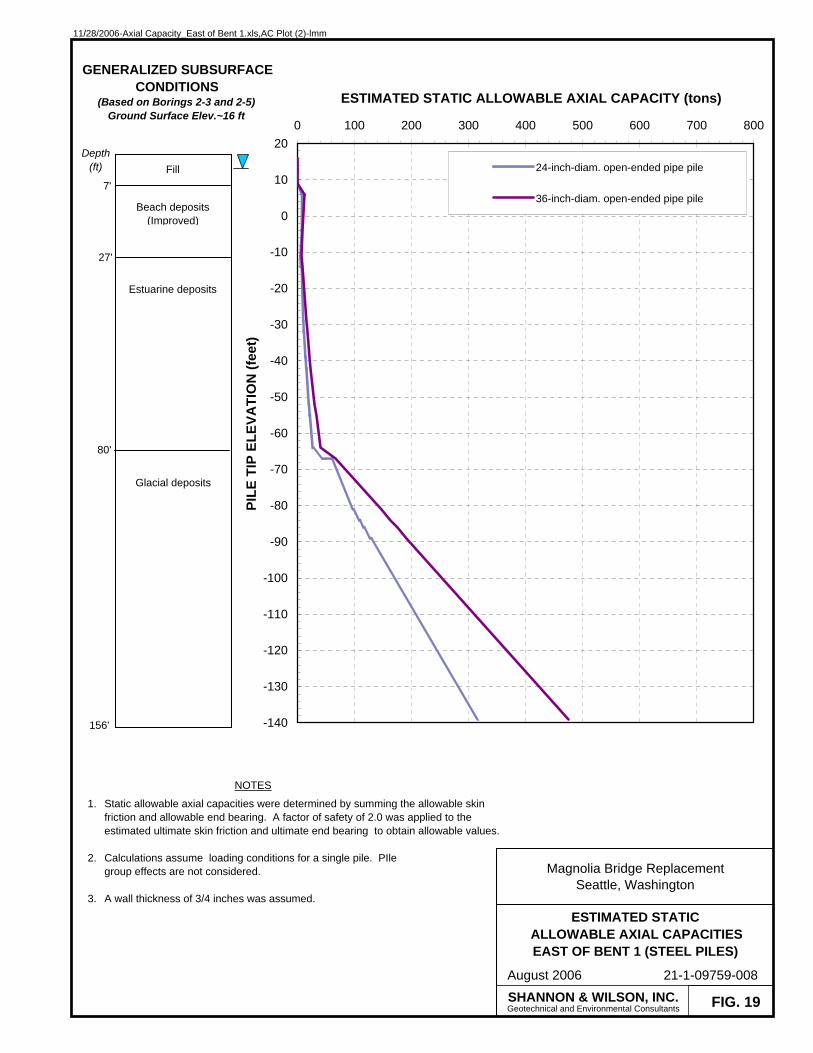
11/28/2006-Axial Capacity_East of Bent 1.xls,AC Plot (2)-lmm
FIG. 19
ESTIMATED STATICALLOWABLE AXIAL CAPACITIESEAST OF BENT 1 (STEEL PILES)
Magnolia Bridge ReplacementSeattle, Washington
August 2006 21-1-09759-008
-140
-130
-120
-110
-100
-90
-80
-70
-60
-50
-40
-30
-20
-10
0
10
200 100 200 300 400 500 600 700 800
ESTIMATED STATIC ALLOWABLE AXIAL CAPACITY (tons)
PILE
TIP
ELE
VATI
ON
(fee
t)
24-inch-diam. open-ended pipe pile
36-inch-diam. open-ended pipe pile
SHANNON & WILSON, INC.Geotechnical and Environmental Consultants
NOTES
1.
2.
3.
Static allowable axial capacities were determined by summing the allowable skin friction and allowable end bearing. A factor of safety of 2.0 was applied to the estimated ultimate skin friction and ultimate end bearing to obtain allowable values.
Calculations assume loading conditions for a single pile. PIle group effects are not considered.
A wall thickness of 3/4 inches was assumed.
Fill
Estuarine deposits
7'
80'
GENERALIZED SUBSURFACECONDITIONS
(Based on Borings 2-3 and 2-5)Ground Surface Elev.~16 ft
27'
Beach deposits(Improved)
Glacial deposits
Depth (ft)
156'
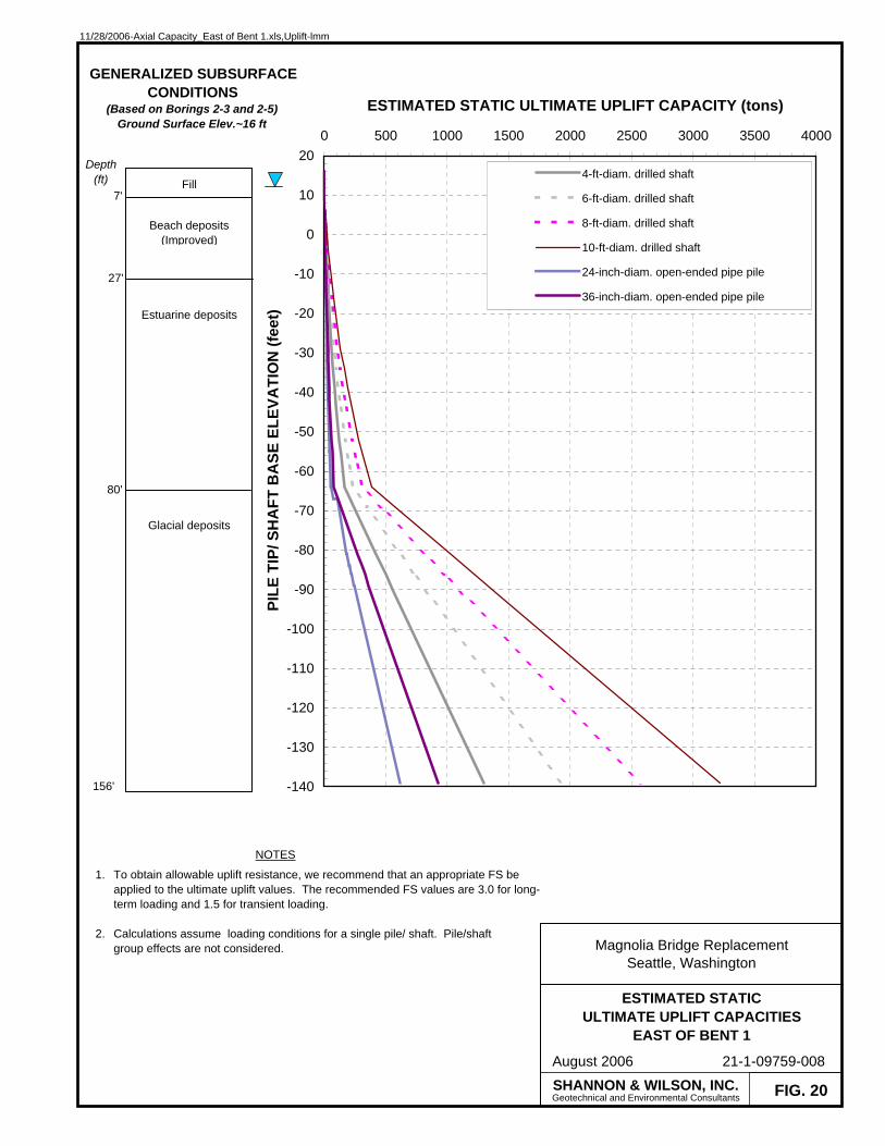
11/28/2006-Axial Capacity_East of Bent 1.xls,Uplift-lmm
FIG. 20
ESTIMATED STATICULTIMATE UPLIFT CAPACITIES
EAST OF BENT 1
Magnolia Bridge ReplacementSeattle, Washington
August 2006 21-1-09759-008
-140
-130
-120
-110
-100
-90
-80
-70
-60
-50
-40
-30
-20
-10
0
10
200 500 1000 1500 2000 2500 3000 3500 4000
ESTIMATED STATIC ULTIMATE UPLIFT CAPACITY (tons)
PILE
TIP
/ SH
AFT
BA
SE E
LEVA
TIO
N (f
eet)
4-ft-diam. drilled shaft
6-ft-diam. drilled shaft
8-ft-diam. drilled shaft
10-ft-diam. drilled shaft
24-inch-diam. open-ended pipe pile
36-inch-diam. open-ended pipe pile
SHANNON & WILSON, INC.Geotechnical and Environmental Consultants
NOTES
1.
2.
To obtain allowable uplift resistance, we recommend that an appropriate FS be applied to the ultimate uplift values. The recommended FS values are 3.0 for long-term loading and 1.5 for transient loading.
Calculations assume loading conditions for a single pile/ shaft. Pile/shaft group effects are not considered.
GENERALIZED SUBSURFACECONDITIONS
(Based on Borings 2-3 and 2-5)Ground Surface Elev.~16 ft
Depth (ft) Fill
Estuarine deposits
7'
80'
27'
Beach deposits(Improved)
Glacial deposits
156'

11/28/2006-Axial Capacity_15th Ave W.xls,AC Plot-lmm
FIG. 21
ESTIMATED STATICALLOWABLE AXIAL CAPACITIES
15TH AVE WEST (DRILLED SHAFTS)
Magnolia Bridge ReplacementSeattle, Washington
August 2006 21-1-09759-008
-110
-100
-90
-80
-70
-60
-50
-40
-30
-20
-10
0
10
200 500 1000 1500 2000 2500 3000 3500 4000
ESTIMATED STATIC ALLOWABLE AXIAL CAPACITY (tons)
SHA
FT B
ASE
ELE
VATI
ON
(fee
t)
4-ft-diam. drilled shaft
6-ft-diam. drilled shaft
8-ft-diam. drilled shaft
10-ft-diam. drilled shaft
SHANNON & WILSON, INC.Geotechnical and Environmental Consultants
NOTES
1.
2.
3.
4.
Static allowable axial capacities were determined by summing the allowable skin friction and allowable end bearing. For drilled shafts the allowable end bearing was equal to the mobilized end bearing. This mobilized end bearing was limited to 50% of the ultimate end bearing. A factor of safety of 2.0 was applied to the estimated ultimate skin friction and ultimate end bearing, where applicable, to obtain allowable values.
Calculations assume loading conditions for a single shaft. Shaft group effects are not considered.
Full end bearing is not achieved until the shaft penetrates at least 3 to 5 feet into the bearing layer.
Estimated capacities assume that if casing is used, it will be removedafter the shaft installation. If, however, the casing is left in place, grouting should be used to fill all potential voids around the casing and the estimated capacities given above should be re-evaluated.
Fill8'
GENERALIZED SUBSURFACECONDITIONS
(Based on Borings 2-2)Ground Surface Elev.~16 ft
30'
Beach deposits(Improved)
Glacial deposits
Depth (ft)
126'
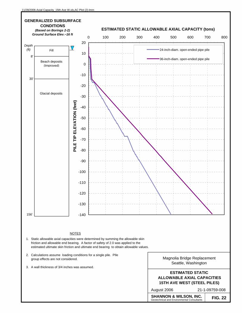
11/28/2006-Axial Capacity_15th Ave W.xls,AC Plot (2)-lmm
FIG. 22
ESTIMATED STATICALLOWABLE AXIAL CAPACITIES15TH AVE WEST (STEEL PILES)
Magnolia Bridge ReplacementSeattle, Washington
August 2006 21-1-09759-008
-140
-130
-120
-110
-100
-90
-80
-70
-60
-50
-40
-30
-20
-10
0
10
200 100 200 300 400 500 600 700 800
ESTIMATED STATIC ALLOWABLE AXIAL CAPACITY (tons)
PILE
TIP
ELE
VATI
ON
(fee
t)
24-inch-diam. open-ended pipe pile
36-inch-diam. open-ended pipe pile
SHANNON & WILSON, INC.Geotechnical and Environmental Consultants
NOTES
1.
2.
3.
Static allowable axial capacities were determined by summing the allowable skin friction and allowable end bearing. A factor of safety of 2.0 was applied to the estimated ultimate skin friction and ultimate end bearing to obtain allowable values.
Calculations assume loading conditions for a single pile. PIle group effects are not considered.
A wall thickness of 3/4 inches was assumed.
Fill
8'
GENERALIZED SUBSURFACECONDITIONS
(Based on Borings 2-2)Ground Surface Elev.~16 ft
30'
Beach deposits(Improved)
Glacial deposits
Depth (ft)
156'

11/28/2006-Axial Capacity_15th Ave W.xls,Uplift-lmm
FIG. 23
ESTIMATED STATICULTIMATE UPLIFT CAPACITIES
15TH AVE WEST
Magnolia Bridge ReplacementSeattle, Washington
August 2006 21-1-09759-008
-140
-130
-120
-110
-100
-90
-80
-70
-60
-50
-40
-30
-20
-10
0
10
200 500 1000 1500 2000 2500 3000 3500 4000
ESTIMATED STATIC ULTIMATE UPLIFT CAPACITY (tons)
PILE
TIP
/ SH
AFT
BA
SE E
LEVA
TIO
N (f
eet)
4-ft-diam. drilled shaft
6-ft-diam. drilled shaft
8-ft-diam. drilled shaft
10-ft-diam. drilled shaft
24-inch-diam. open-ended pipe pile
36-inch-diam. open-ended pipe pile
SHANNON & WILSON, INC.Geotechnical and Environmental Consultants
NOTES
1.
2.
To obtain allowable uplift resistance, we recommend that an appropriate FS be applied to the ultimate uplift values. The recommended FS values are 3.0 for long-term loading and 1.5 for transient loading.
Calculations assume loading conditions for a single pile/ shaft. Pile/shaft group effects are not considered.
GENERALIZED SUBSURFACECONDITIONS
(Based on Borings 2-2)Ground Surface Elev.~16 ft
Depth (ft) Fill
8'
30'
Beach deposits(Improved)
Glacial deposits
156'
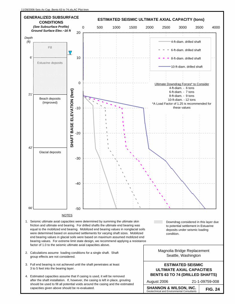
11/28/2006-Seis Ax Cap_Bents 63 to 74.xls,AC Plot-lmm
FIG. 24
ESTIMATED SEISMICULTIMATE AXIAL CAPACITIES
BENTS 63 TO 74 (DRILLED SHAFTS)
Magnolia Bridge ReplacementSeattle, Washington
August 2006 21-1-09759-008
-50
-40
-30
-20
-10
0
10
200 500 1000 1500 2000 2500 3000 3500 4000
ESTIMATED SEISMIC ULTIMATE AXIAL CAPACITY (tons)
SHA
FT B
ASE
ELE
VATI
ON
(fee
t)
4-ft-diam. drilled shaft
6-ft-diam. drilled shaft
8-ft-diam. drilled shaft
10-ft-diam. drilled shaft
SHANNON & WILSON, INC.Geotechnical and Environmental Consultants
NOTES
1.
2.
3.
4.
Seismic ultimate axial capacities were determined by summing the ultimate skin friction and ultimate end bearing. For drilled shafts the ultimate end bearing was equal to the mobilized end bearing. Mobilized end bearing values in nonglacial soils were determined based on assumed settlements for varying shaft sizes. Mobilized end bearing values in glacial soils were based on maximum assumed moblized end bearing values. For extreme limit state design, we recommend applying a resistance factor of 1.0 to the seismic ultimate axial capacities above.
Calculations assume loading conditions for a single shaft. Shaft group effects are not considered.
Full end bearing is not achieved until the shaft penetrates at least 3 to 5 feet into the bearing layer.
Estimated capacities assume that if casing is used, it will be removedafter the shaft installation. If, however, the casing is left in place, grouting should be used to fill all potential voids around the casing and the estimated capacities given above should be re-evaluated.
Fill
Beach deposits(Improved)
Glacial deposits
6'
42'
GENERALIZED SUBSURFACECONDITIONS
(See Subsurface Profile)Ground Surface Elev.~16 ft
Depth (ft)
21'
Estuarine deposits
Downdrag considered in this layer due to potential settlement in Estuarine deposits under seismic loading condition.
Ultimate Downdrag Forces* to Consider4-ft-diam. - 6 tons6-ft-diam. - 7 tons8-ft-diam. - 9 tons
10-ft-diam. - 12 tons*A Load Factor of 1.25 is recommended for
these values
66'

11/28/2006-Seis Ax Cap_Bents 63 to 74.xls,AC Plot (2)-lmm
FIG. 25
ESTIMATED SEISMICULTIMATE AXIAL CAPACITIES
BENTS 63 TO 74 (STEEL PILES)
Magnolia Bridge ReplacementSeattle, Washington
August 2006 21-1-09759-008
-80
-70
-60
-50
-40
-30
-20
-10
0
10
200 200 400 600 800 1000 1200 1400
ESTIMATED SEISMIC ULTIMATE AXIAL CAPACITY (tons)
PILE
TIP
ELE
VATI
ON
(fee
t)
24-in-diam. opened-ended pipe pile
36-in-diam. opened-ended pipe pile
SHANNON & WILSON, INC.Geotechnical and Environmental Consultants
NOTES
1.
2.
3.
Seismic ultimate axial capacities were determined by summing the ultimate skin friction and ultimate end bearing. For extreme limit state design, we recommend applying a resistance factor of 1.0 to the seismic ultimate axial capacities above.
Calculations assume loading conditions for a single pile. PIlegroup effects are not considered.
A wall thickness of 3/4 inches was assumed.
Fill
Beach deposits(Improved)
Glacial deposits
6'
42'
GENERALIZED SUBSURFACECONDITIONS
(See Subsurface Profile)Ground Surface Elev.~16 ft
Depth (ft)
21'
Estuarine deposits
Downdrag considered in this layer due to potential settlement in Estuarine deposits under seismic loading condition.
Ultimate Downdrag Forces* to Consider24-in-diam. - 2 tons36-in-diam. - 3 tons
*A Load Factor of 1.25 is recommended for these values
96'
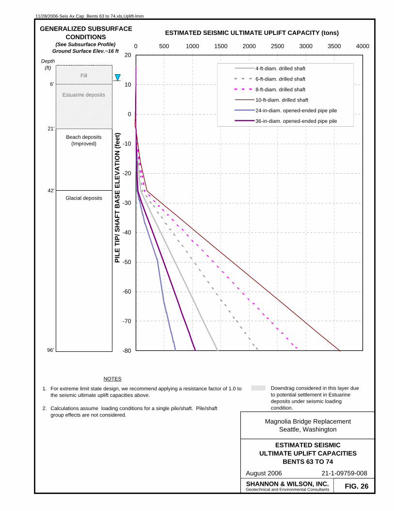
11/28/2006-Seis Ax Cap_Bents 63 to 74.xls,Uplift-lmm
FIG. 26
ESTIMATED SEISMICULTIMATE UPLIFT CAPACITIES
BENTS 63 TO 74
Magnolia Bridge ReplacementSeattle, Washington
August 2006 21-1-09759-008
-80
-70
-60
-50
-40
-30
-20
-10
0
10
200 500 1000 1500 2000 2500 3000 3500 4000
ESTIMATED SEISMIC ULTIMATE UPLIFT CAPACITY (tons)
PILE
TIP
/ SH
AFT
BA
SE E
LEVA
TIO
N (f
eet)
4-ft-diam. drilled shaft
6-ft-diam. drilled shaft
8-ft-diam. drilled shaft
10-ft-diam. drilled shaft
24-in-diam. opened-ended pipe pile
36-in-diam. opened-ended pipe pile
SHANNON & WILSON, INC.Geotechnical and Environmental Consultants
NOTES
1.
2.
For extreme limit state design, we recommend applying a resistance factor of 1.0 to the seismic ultimate uplift capacities above.
Calculations assume loading conditions for a single pile/shaft. Pile/shaft group effects are not considered.
Fill
Beach deposits(Improved)
Glacial deposits
6'
42'
GENERALIZED SUBSURFACECONDITIONS
(See Subsurface Profile)Ground Surface Elev.~16 ft
21'
Estuarine deposits
Depth (ft)
Downdrag considered in this layer due to potential settlement in Estuarine deposits under seismic loading condition.
96'

11/28/2006-Seis Ax Cap_Bents 47 to 62.xls,AC Plot-lmm
FIG. 27
ESTIMATED SEISMICULTIMATE AXIAL CAPACITIES
BENTS 47 TO 62 (DRILLED SHAFTS)
Magnolia Bridge ReplacementSeattle, Washington
August 2006 21-1-09759-008
-50
-40
-30
-20
-10
0
10
200 500 1000 1500 2000 2500 3000 3500 4000
ESTIMATED SEISMIC ULTIMATE AXIAL CAPACITY (tons)
SHA
FT B
ASE
ELE
VATI
ON
(fee
t)
4-ft-diam. drilled shaft
6-ft-diam. drilled shaft
8-ft-diam. drilled shaft
10-ft-diam. drilled shaft
SHANNON & WILSON, INC.Geotechnical and Environmental Consultants
NOTES
1.
2.
3.
4.
Seismic ultimate axial capacities were determined by summing the ultimate skin friction and ultimate end bearing. For drilled shafts the ultimate end bearing was equal to the mobilized end bearing. Mobilized end bearing values in nonglacial soils were determined based on assumed settlements for varying shaft sizes. Mobilized end bearing values in glacial soils were based on maximum assumed moblized end bearing values. For extreme limit state design, we recommend applying a resistance factor of 1.0 to the seismic ultimate axial capacities above
Calculations assume loading conditions for a single shaft. Shaft group effects are not considered.
Full end bearing is not achieved until the shaft penetrates at least 3 to 5 feet into the bearing layer.
Estimated capacities assume that if casing is used, it will be removedafter the shaft installation. If, however, the casing is left in place, grouting should be used to fill all potential voids around the casing and the estimated capacities given above should be re-evaluated.
Fill
Beach deposits(Improved)
Glacial deposits
12'
50'
GENERALIZED SUBSURFACECONDITIONS
(See Subsurface Profile)Ground Surface Elev.~16 ft
Depth (ft)
66'

11/28/2006-Seis Ax Cap_Bents 47 to 62.xls,AC Plot (2)-lmm
FIG. 28
ESTIMATED SEISMICULTIMATE AXIAL CAPACITIES
BENTS 47 TO 62 (STEEL PILES)
Magnolia Bridge ReplacementSeattle, Washington
August 2006 21-1-09759-008
-80
-70
-60
-50
-40
-30
-20
-10
0
10
200 200 400 600 800 1000 1200 1400
ESTIMATED SEISMIC ULTIMATE AXIAL CAPACITY (tons)
PILE
TIP
ELE
VATI
ON
(fee
t)
24-in-diam. open-ended pipe pile
36-in-diam. open-ended pipe pile
SHANNON & WILSON, INC.Geotechnical and Environmental Consultants
NOTES
1.
2.
3.
Seismic ultimate axial capacities were determined by summing the ultimate skin friction and ultimate end bearing. For extreme limit state design, we recommend applying a resistance factor of 1.0 to the seismic ultimate axial capacities above.
Calculations assume loading conditions for a single pile. Pile group effects are not considered.
A wall thickness of 3/4 inches was assumed.
Fill
Beach deposits(Improved)
Glacial deposits
12'
50'
GENERALIZED SUBSURFACECONDITIONS
(See Subsurface Profile)Ground Surface Elev.~16 ft
Depth (ft)
96'

11/28/2006-Seis Ax Cap_Bents 47 to 62.xls,Uplift-lmm
FIG. 29
ESTIMATED SEISMICULTIMATE UPLIFT CAPACITIES
BENTS 47 TO 62
Magnolia Bridge ReplacementSeattle, Washington
August 2006 21-1-09759-008
-80
-70
-60
-50
-40
-30
-20
-10
0
10
200 500 1000 1500 2000 2500 3000 3500 4000
ESTIMATED SEISMIC ULTIMATE UPLIFT CAPACITY (tons)
PILE
TIP
/ SH
AFT
BA
SE E
LEVA
TIO
N (f
eet)
4-ft-diam. drilled shaft
6-ft-diam. drilled shaft
8-ft-diam. drilled shaft
10-ft-diam. drilled shaft
24-in-diam. open-ended pipe pile
36-in-diam. open-ended pipe pile
SHANNON & WILSON, INC.Geotechnical and Environmental Consultants
NOTES
1.
2.
For extreme limit state design, we recommend applying a resistance factor of 1.0 to the seismic ultimate uplift capacities above.
Calculations assume loading conditions for a single pile/shaft. Pile/shaft group effects are not considered.
Fill
Beach deposits(Improved)
Glacial deposits
12'
50'
GENERALIZED SUBSURFACECONDITIONS
(See Subsurface Profile)Ground Surface Elev.~16 ft
Depth (ft)
96'
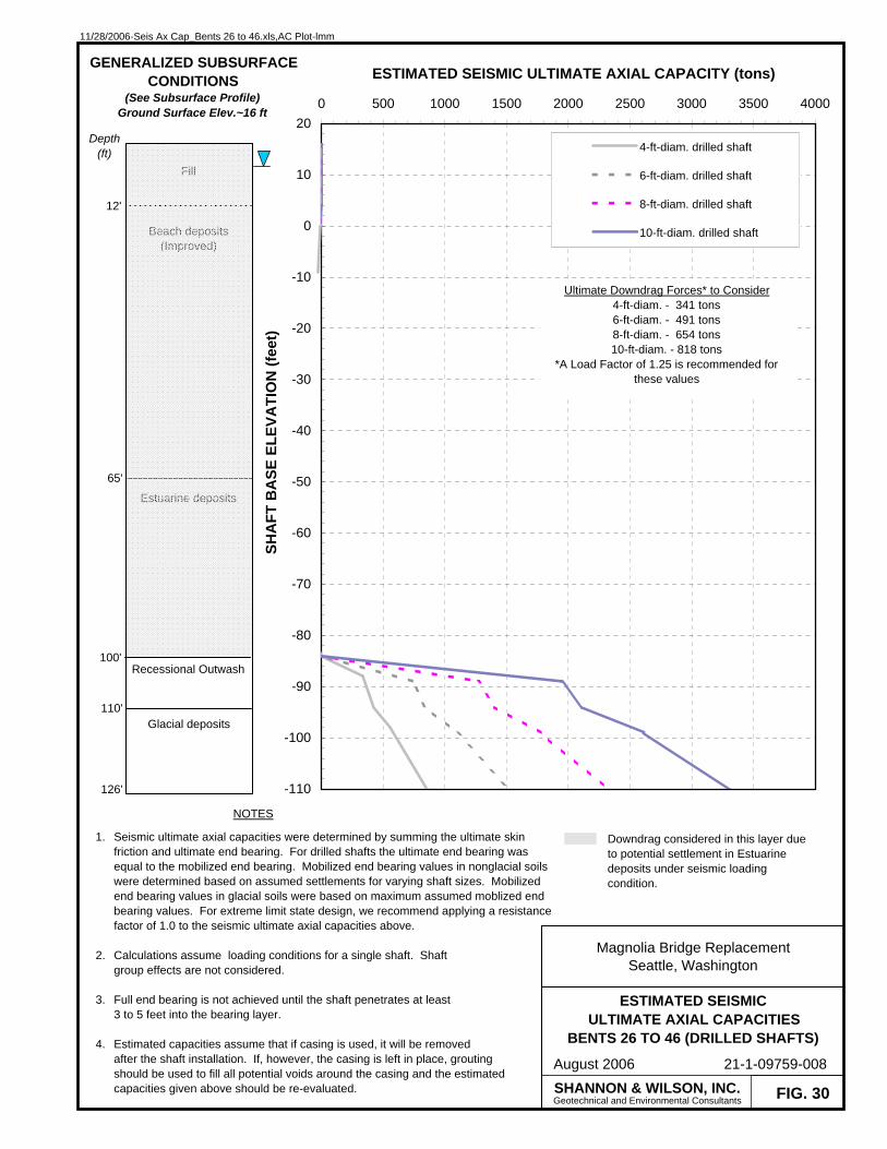
11/28/2006-Seis Ax Cap_Bents 26 to 46.xls,AC Plot-lmm
FIG. 30
ESTIMATED SEISMICULTIMATE AXIAL CAPACITIES
BENTS 26 TO 46 (DRILLED SHAFTS)
Magnolia Bridge ReplacementSeattle, Washington
August 2006 21-1-09759-008
-110
-100
-90
-80
-70
-60
-50
-40
-30
-20
-10
0
10
200 500 1000 1500 2000 2500 3000 3500 4000
ESTIMATED SEISMIC ULTIMATE AXIAL CAPACITY (tons)
SHA
FT B
ASE
ELE
VATI
ON
(fee
t)
4-ft-diam. drilled shaft
6-ft-diam. drilled shaft
8-ft-diam. drilled shaft
10-ft-diam. drilled shaft
SHANNON & WILSON, INC.Geotechnical and Environmental Consultants
NOTES
1.
2.
3.
4.
Seismic ultimate axial capacities were determined by summing the ultimate skin friction and ultimate end bearing. For drilled shafts the ultimate end bearing was equal to the mobilized end bearing. Mobilized end bearing values in nonglacial soils were determined based on assumed settlements for varying shaft sizes. Mobilized end bearing values in glacial soils were based on maximum assumed moblized end bearing values. For extreme limit state design, we recommend applying a resistance factor of 1.0 to the seismic ultimate axial capacities above.
Calculations assume loading conditions for a single shaft. Shaft group effects are not considered.
Full end bearing is not achieved until the shaft penetrates at least 3 to 5 feet into the bearing layer.
Estimated capacities assume that if casing is used, it will be removedafter the shaft installation. If, however, the casing is left in place, grouting should be used to fill all potential voids around the casing and the estimated capacities given above should be re-evaluated.
Fill
Estuarine deposits
Recessional Outwash
12'
100'
GENERALIZED SUBSURFACECONDITIONS
(See Subsurface Profile)Ground Surface Elev.~16 ft
65'
Beach deposits(Improved)
Glacial deposits110'
Depth (ft)
Downdrag considered in this layer due to potential settlement in Estuarine deposits under seismic loading condition.
Ultimate Downdrag Forces* to Consider4-ft-diam. - 341 tons6-ft-diam. - 491 tons8-ft-diam. - 654 tons10-ft-diam. - 818 tons
*A Load Factor of 1.25 is recommended for these values
126'
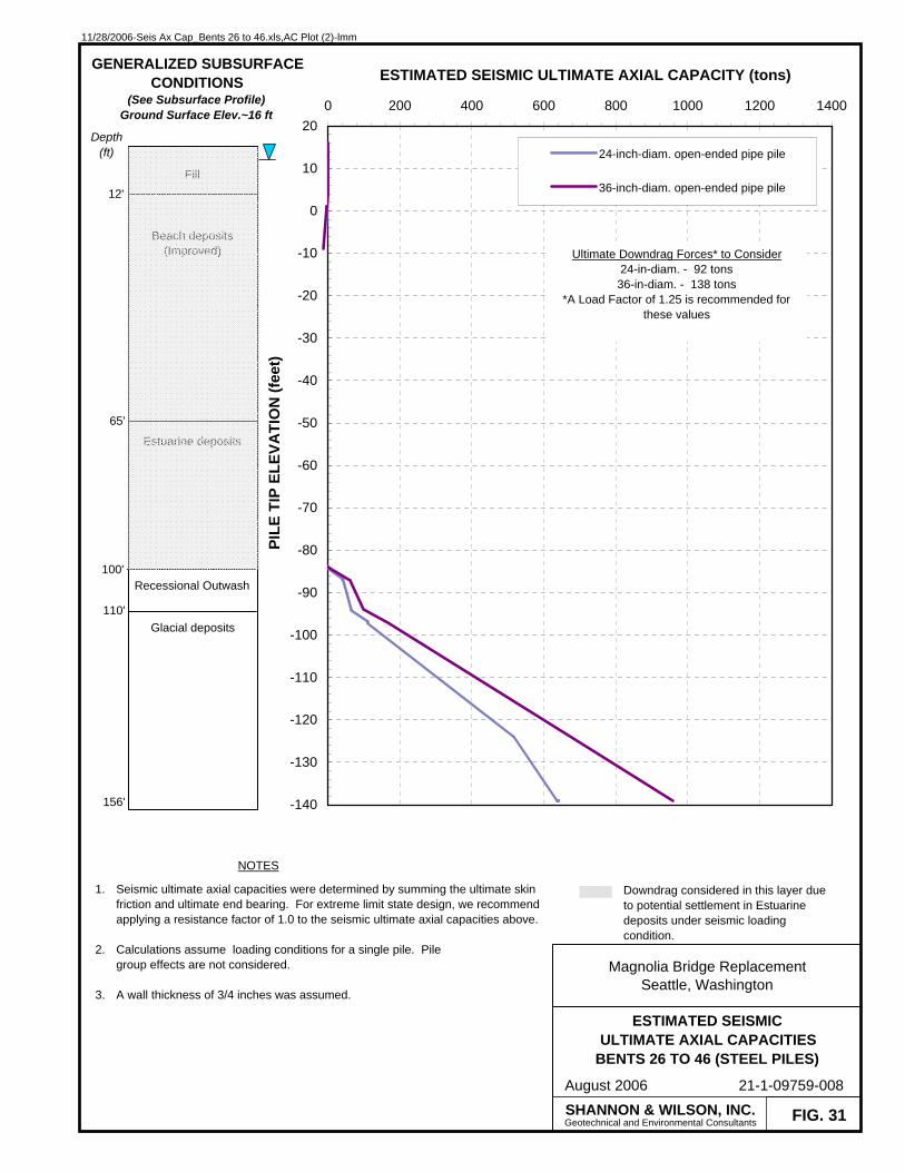
11/28/2006-Seis Ax Cap_Bents 26 to 46.xls,AC Plot (2)-lmm
FIG. 31
ESTIMATED SEISMICULTIMATE AXIAL CAPACITIES
BENTS 26 TO 46 (STEEL PILES)
Magnolia Bridge ReplacementSeattle, Washington
August 2006 21-1-09759-008
-140
-130
-120
-110
-100
-90
-80
-70
-60
-50
-40
-30
-20
-10
0
10
200 200 400 600 800 1000 1200 1400
ESTIMATED SEISMIC ULTIMATE AXIAL CAPACITY (tons)
PILE
TIP
ELE
VATI
ON
(fee
t)
24-inch-diam. open-ended pipe pile
36-inch-diam. open-ended pipe pile
SHANNON & WILSON, INC.Geotechnical and Environmental Consultants
NOTES
1.
2.
3.
Seismic ultimate axial capacities were determined by summing the ultimate skin friction and ultimate end bearing. For extreme limit state design, we recommend applying a resistance factor of 1.0 to the seismic ultimate axial capacities above.
Calculations assume loading conditions for a single pile. Pile group effects are not considered.
A wall thickness of 3/4 inches was assumed.
Fill
Estuarine deposits
Recessional Outwash
12'
100'
GENERALIZED SUBSURFACECONDITIONS
(See Subsurface Profile)Ground Surface Elev.~16 ft
65'
Beach deposits(Improved)
Glacial deposits110'
Depth (ft)
Downdrag considered in this layer due to potential settlement in Estuarine deposits under seismic loading condition.
Ultimate Downdrag Forces* to Consider24-in-diam. - 92 tons36-in-diam. - 138 tons
*A Load Factor of 1.25 is recommended for these values
156'
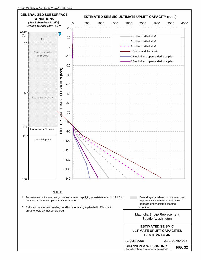
11/28/2006-Seis Ax Cap_Bents 26 to 46.xls,Uplift-lmm
FIG. 32
ESTIMATED SEISMICULTIMATE UPLIFT CAPACITIES
BENTS 26 TO 46
Magnolia Bridge ReplacementSeattle, Washington
August 2006 21-1-09759-008
-140
-130
-120
-110
-100
-90
-80
-70
-60
-50
-40
-30
-20
-10
0
10
200 500 1000 1500 2000 2500 3000 3500 4000
ESTIMATED SEISMIC ULTIMATE UPLIFT CAPACITY (tons)
PILE
TIP
/ SH
AFT
BA
SE E
LEVA
TIO
N (f
eet)
4-ft-diam. drilled shaft
6-ft-diam. drilled shaft
8-ft-diam. drilled shaft
10-ft-diam. drilled shaft
24-inch-diam. open-ended pipe pile
36-inch-diam. open-ended pipe pile
SHANNON & WILSON, INC.Geotechnical and Environmental Consultants
NOTES
1.
2.
For extreme limit state design, we recommend applying a resistance factor of 1.0 to the seismic ultimate uplift capacities above.
Calculations assume loading conditions for a single pile/shaft. Pile/shaft group effects are not considered.
Fill
Estuarine deposits
Recessional Outwash
12'
100'
GENERALIZED SUBSURFACECONDITIONS
(See Subsurface Profile)Ground Surface Elev.~16 ft
65'
Beach deposits(Improved)
Glacial deposits110'
Depth (ft)
Downdrag considered in this layer due to potential settlement in Estuarine deposits under seismic loading condition.
156'

11/28/2006-Seis Ax Cap_Bents 18 to 25.xls,AC Plot-lmm
FIG. 33
ESTIMATED SEISMICULTIMATE AXIAL CAPACITIES
BENTS 18 TO 25 (DRILLED SHAFTS)
Magnolia Bridge ReplacementSeattle, Washington
August 2006 21-1-09759-008
-110
-100
-90
-80
-70
-60
-50
-40
-30
-20
-10
0
10
200 500 1000 1500 2000 2500 3000 3500 4000
ESTIMATED SEISMIC ULTIMATE AXIAL CAPACITY (tons)
SHA
FT B
ASE
ELE
VATI
ON
(fee
t)
4-ft-diam. drilled shaft
6-ft-diam. drilled shaft
8-ft-diam. drilled shaft
10-ft-diam. drilled shaft
SHANNON & WILSON, INC.Geotechnical and Environmental Consultants
NOTES
1.
2.
3.
4.
Seismic ultimate axial capacities were determined by summing the ultimate skin friction and ultimate end bearing. For drilled shafts the ultimate end bearing was equal to the mobilized end bearing. Mobilized end bearing values in nonglacial soils were determined based on assumed settlements for varying shaft sizes. Mobilized end bearing values in glacial soils were based on maximum assumed moblized end bearing values. For extreme limit state design, we recommend applying a resistance factor of 1.0 to the seismic ultimate axial capacities above.
Calculations assume loading conditions for a single shaft. Shaft group effects are not considered.
Full end bearing is not achieved until the shaft penetrates at least 3 to 5 feet into the bearing layer.
Estimated capacities assume that if casing is used, it will be removedafter the shaft installation. If, however, the casing is left in place, grouting should be used to fill all potential voids around the casing and the estimated capacities given above should be re-evaluated.
Fill
Estuarine deposits
Estuarine deposits
11'
73'
GENERALIZED SUBSURFACECONDITIONS
(See Subsurface Profile)Ground Surface Elev.~16 ft
35'
Beach deposits(Improved)
Glacial deposits
110'
Beach deposits(Improved)
40'
Recessional Outwash102'
Depth (ft)
Downdrag considered in this layer due to potential settlement in Estuarine deposits under seismic loading condition.
Ultimate Downdrag Forces* to Consider4-ft-diam. - 377 tons6-ft-diam. - 541 tons8-ft-diam. - 721 tons
10-ft-diam. - 901 tons*A Load Factor of 1.25 is recommended for
these values
126'

11/28/2006-Seis Ax Cap_Bents 18 to 25.xls,AC Plot (2)-lmm
FIG. 34
ESTIMATED SEISMICULTIMATE AXIAL CAPACITIES
BENTS 18 TO 25 (STEEL PILES)
Magnolia Bridge ReplacementSeattle, Washington
August 2006 21-1-09759-008
-140
-130
-120
-110
-100
-90
-80
-70
-60
-50
-40
-30
-20
-10
0
10
200 200 400 600 800 1000 1200 1400
ESTIMATED SEISMIC ULTIMATE AXIAL CAPACITY (tons)
PILE
TIP
ELE
VATI
ON
(fee
t)
24-inch-diam. open-ended pipe pile
36-inch-diam. open-ended pipe pile
SHANNON & WILSON, INC.Geotechnical and Environmental Consultants
NOTES
1.
2.
3.
Seismic ultimate axial capacities were determined by summing the ultimate skin friction and ultimate end bearing. For extreme limit state design, we recommend applying a resistance factor of 1.0 to the seismic ultimate axial capacities above.
Calculations assume loading conditions for a single pile. Pilegroup effects are not considered.
A wall thickness of 3/4 inches was assumed.
Fill
Estuarine deposits
Estuarine deposits
11'
73'
GENERALIZED SUBSURFACECONDITIONS
(See Subsurface Profile)Ground Surface Elev.~16 ft
35'
Beach deposits(Improved)
Glacial deposits110'
Beach deposits(Improved)
40'
Recessional Outwash102'
Depth (ft)
Downdrag considered in this layer due to potential settlement in Estuarine deposits under seismic loading condition.
Ultimate Downdrag Forces* to Consider24-in-diam. - 105 tons36-in-diam. - 157 tons
*A Load Factor of 1.25 is recommended for these values
156'
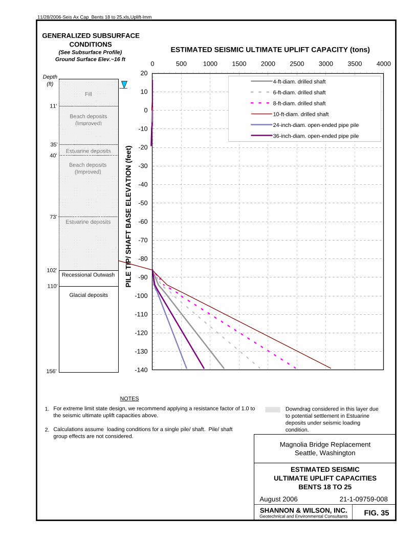
11/28/2006-Seis Ax Cap_Bents 18 to 25.xls,Uplift-lmm
FIG. 35
ESTIMATED SEISMICULTIMATE UPLIFT CAPACITIES
BENTS 18 TO 25
Magnolia Bridge ReplacementSeattle, Washington
August 2006 21-1-09759-008
-140
-130
-120
-110
-100
-90
-80
-70
-60
-50
-40
-30
-20
-10
0
10
200 500 1000 1500 2000 2500 3000 3500 4000
ESTIMATED SEISMIC ULTIMATE UPLIFT CAPACITY (tons)
PILE
TIP
/ SH
AFT
BA
SE E
LEVA
TIO
N (f
eet)
4-ft-diam. drilled shaft
6-ft-diam. drilled shaft
8-ft-diam. drilled shaft
10-ft-diam. drilled shaft
24-inch-diam. open-ended pipe pile
36-inch-diam. open-ended pipe pile
SHANNON & WILSON, INC.Geotechnical and Environmental Consultants
NOTES
1.
2.
For extreme limit state design, we recommend applying a resistance factor of 1.0 to the seismic ultimate uplift capacities above.
Calculations assume loading conditions for a single pile/ shaft. Pile/ shaft group effects are not considered.
Fill
Estuarine deposits
Estuarine deposits
11'
73'
GENERALIZED SUBSURFACECONDITIONS
(See Subsurface Profile)Ground Surface Elev.~16 ft
35'
Beach deposits(Improved)
Glacial deposits110'
Beach deposits(Improved)
40'
Recessional Outwash102'
Depth (ft)
Downdrag considered in this layer due to potential settlement in Estuarine deposits under seismic loading condition.
156'
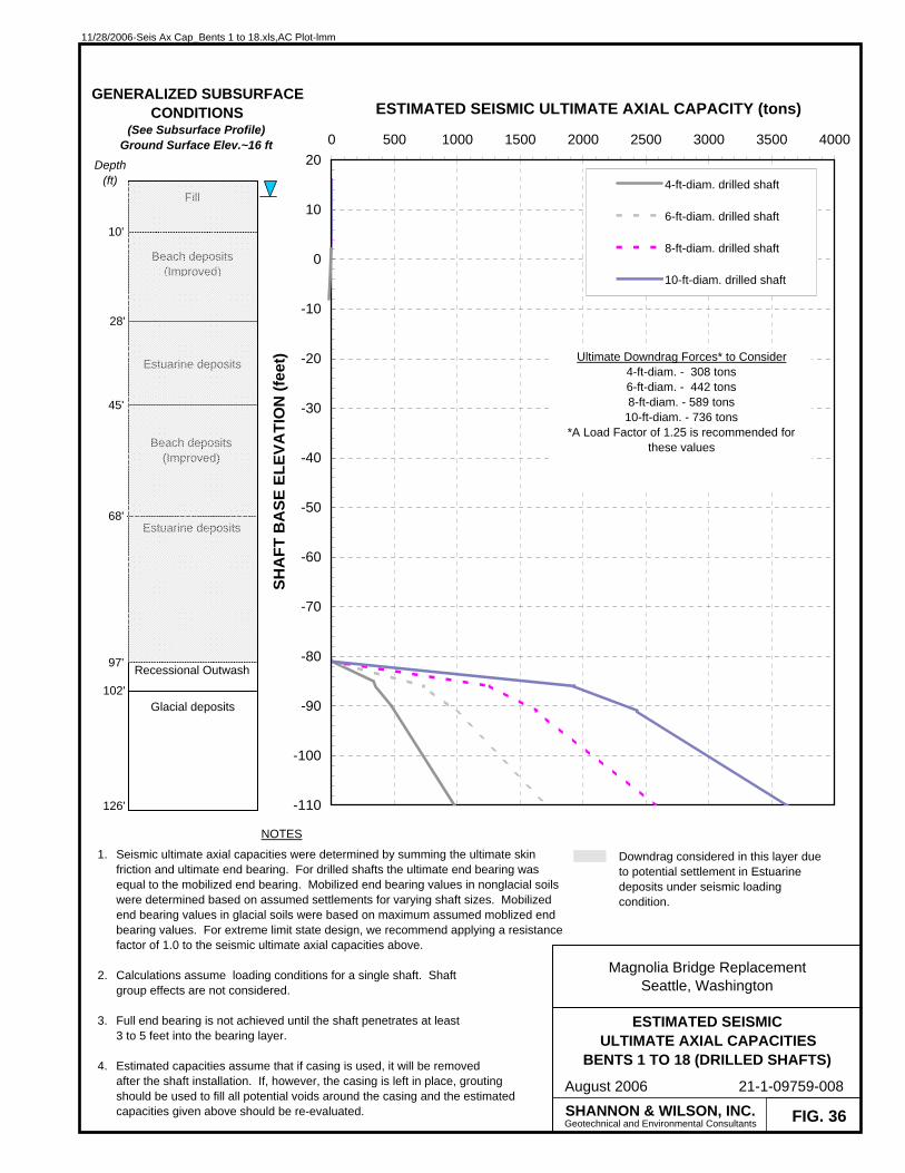
11/28/2006-Seis Ax Cap_Bents 1 to 18.xls,AC Plot-lmm
FIG. 36
ESTIMATED SEISMICULTIMATE AXIAL CAPACITIES
BENTS 1 TO 18 (DRILLED SHAFTS)
Magnolia Bridge ReplacementSeattle, Washington
August 2006 21-1-09759-008
-110
-100
-90
-80
-70
-60
-50
-40
-30
-20
-10
0
10
200 500 1000 1500 2000 2500 3000 3500 4000
ESTIMATED SEISMIC ULTIMATE AXIAL CAPACITY (tons)
SHA
FT B
ASE
ELE
VATI
ON
(fee
t)
4-ft-diam. drilled shaft
6-ft-diam. drilled shaft
8-ft-diam. drilled shaft
10-ft-diam. drilled shaft
SHANNON & WILSON, INC.Geotechnical and Environmental Consultants
NOTES
1.
2.
3.
4.
Seismic ultimate axial capacities were determined by summing the ultimate skin friction and ultimate end bearing. For drilled shafts the ultimate end bearing was equal to the mobilized end bearing. Mobilized end bearing values in nonglacial soils were determined based on assumed settlements for varying shaft sizes. Mobilized end bearing values in glacial soils were based on maximum assumed moblized end bearing values. For extreme limit state design, we recommend applying a resistance factor of 1.0 to the seismic ultimate axial capacities above.
Calculations assume loading conditions for a single shaft. Shaft group effects are not considered.
Full end bearing is not achieved until the shaft penetrates at least 3 to 5 feet into the bearing layer.
Estimated capacities assume that if casing is used, it will be removedafter the shaft installation. If, however, the casing is left in place, grouting should be used to fill all potential voids around the casing and the estimated capacities given above should be re-evaluated.
Fill
Estuarine deposits
Estuarine deposits
10'
68'
GENERALIZED SUBSURFACECONDITIONS
(See Subsurface Profile)Ground Surface Elev.~16 ft
28'
Beach deposits(Improved)
Glacial deposits102'
Beach deposits(Improved)
45'
Recessional Outwash97'
Depth (ft)
Downdrag considered in this layer due to potential settlement in Estuarine deposits under seismic loading condition.
Ultimate Downdrag Forces* to Consider4-ft-diam. - 308 tons6-ft-diam. - 442 tons8-ft-diam. - 589 tons
10-ft-diam. - 736 tons*A Load Factor of 1.25 is recommended for
these values
126'

11/28/2006-Seis Ax Cap_Bents 1 to 18.xls,AC Plot (2)-lmm
FIG. 37
ESTIMATED SEISMICULTIMATE AXIAL CAPACITIESBENTS 1 TO 18 (STEEL PILES)
Magnolia Bridge ReplacementSeattle, Washington
August 2006 21-1-09759-008
-140
-130
-120
-110
-100
-90
-80
-70
-60
-50
-40
-30
-20
-10
0
10
200 200 400 600 800 1000 1200 1400
ESTIMATED SEISMIC ULTIMATE AXIAL CAPACITY (tons)
PILE
TIP
ELE
VATI
ON
(fee
t)
24-inch-diam. open-ended pipe pile
36-inch-diam. open-ended pipe pile
SHANNON & WILSON, INC.Geotechnical and Environmental Consultants
NOTES
1.
2.
3.
Seismic ultimate axial capacities were determined by summing the ultimate skin friction and ultimate end bearing. For extreme limit state design, we recommend applying a resistance factor of 1.0 to the seismic ultimate axial capacities above.
Calculations assume loading conditions for a single pile. PIle group effects are not considered.
A wall thickness of 3/4 inches was assumed.
Fill
Estuarine deposits
Estuarine deposits
10'
68'
GENERALIZED SUBSURFACECONDITIONS
(See Subsurface Profile)Ground Surface Elev.~16 ft
28'
Beach deposits(Improved)
Glacial deposits102'
Beach deposits(Improved)
45'
Recessional Outwash97'
Depth (ft)
Downdrag considered in this layer due to potential settlement in Estuarine deposits under seismic loading condition.
Ultimate Downdrag Forces* to Consider24-in-diam. - 85 tons36-in-diam. - 128 tons
*A Load Factor of 1.25 is recommended for these values
156'

11/28/2006-Seis Ax Cap_Bents 1 to 18.xls,Uplift-lmm
FIG. 38
ESTIMATED SEISMICULTIMATE UPLIFT CAPACITIES
BENTS 1 TO 18
Magnolia Bridge ReplacementSeattle, Washington
August 2006 21-1-09759-008
-140
-130
-120
-110
-100
-90
-80
-70
-60
-50
-40
-30
-20
-10
0
10
200 500 1000 1500 2000 2500 3000 3500 4000
ESTIMATED SEISMIC ULTIMATE UPLIFT CAPACITY (tons)
PILE
TIP
/ SH
AFT
BA
SE E
LEVA
TIO
N (f
eet)
4-ft-diam. drilled shaft
6-ft-diam. drilled shaft
8-ft-diam. drilled shaft
10-ft-diam. drilled shaft
24-inch-diam. open-ended pipe pile
36-inch-diam. open-ended pipe pile
SHANNON & WILSON, INC.Geotechnical and Environmental Consultants
NOTES
1.
2.
For extreme limit state design, we recommend applying a resistance factor of 1.0 to the seismic ultimate uplift capacities above.
Calculations assume loading conditions for a single pile/ shaft. Pile/shaft group effects are not considered.
Fill
Estuarine deposits
Estuarine deposits
10'
68'
GENERALIZED SUBSURFACECONDITIONS
(See Subsurface Profile)Ground Surface Elev.~16 ft
28'
Beach deposits(Improved)
Glacial deposits102'
Beach deposits(Improved)
45'
Recessional Outwash97'
Depth (ft)
Downdrag considered in this layer due to potential settlement in Estuarine deposits under seismic loading condition.
156'

11/28/2006-Seis Ax Cap_East of Bent 1.xls,AC Plot-lmm
FIG. 39
ESTIMATED SEISMICULTIMATE AXIAL CAPACITIES
EAST OF BENT 1 (DRILLED SHAFTS)
Magnolia Bridge ReplacementSeattle, Washington
August 2006 21-1-09759-008
-110
-100
-90
-80
-70
-60
-50
-40
-30
-20
-10
0
10
200 500 1000 1500 2000 2500 3000 3500 4000
ESTIMATED SEISMIC ULTIMATE AXIAL CAPACITY (tons)
SHA
FT B
ASE
ELE
VATI
ON
(fee
t)
4-ft-diam. drilled shaft
6-ft-diam. drilled shaft
8-ft-diam. drilled shaft
10-ft-diam. drilled shaft
SHANNON & WILSON, INC.Geotechnical and Environmental Consultants
NOTES
1.
2.
3.
4.
Seismic ultimate axial capacities were determined by summing the ultimate skin friction and ultimate end bearing. For drilled shafts the ultimate end bearing was equal to the mobilized end bearing. Mobilized end bearing values in nonglacial soils were determined based on assumed settlements for varying shaft sizes. Mobilized end bearing values in glacial soils were based on maximum assumed moblized end bearing values. For extreme limit state design, we recommend applying a resistance factor of 1.0 to the seismic ultimate axial capacities above.
Calculations assume loading conditions for a single shaft. Shaft group effects are not considered.
Full end bearing is not achieved until the shaft penetrates at least 3 to 5 feet into the bearing layer.
Estimated capacities assume that if casing is used, it will be removedafter the shaft installation. If, however, the casing is left in place, grouting should be used to fill all potential voids around the casing and the estimated capacities given above should be re-evaluated.
Fill
Estuarine deposits
7'
80'
GENERALIZED SUBSURFACECONDITIONS
(Based on Borings 2-3 and 2-5)Ground Surface Elev.~16 ft
27'
Beach deposits(Improved)
Glacial deposits
Depth (ft)
Downdrag considered in this layer due to potential settlement in Estuarine deposits under seismic loading condition.
Ultimate Downdrag Forces* to Consider4-ft-diam. - 129 tons6-ft-diam. - 181 tons8-ft-diam. - 242 tons
10-ft-diam. - 302 tons*A Load Factor of 1.25 is recommended for
these values
126'

11/28/2006-Seis Ax Cap_East of Bent 1.xls,AC Plot (2)-lmm
FIG. 40
ESTIMATED SEISMICULTIMATE AXIAL CAPACITIES
EAST OF BENT 1 (STEEL PILES)
Magnolia Bridge ReplacementSeattle, Washington
August 2006 21-1-09759-008
-140
-130
-120
-110
-100
-90
-80
-70
-60
-50
-40
-30
-20
-10
0
10
200 200 400 600 800 1000 1200 1400
ESTIMATED SEISMIC ULTIMATE AXIAL CAPACITY (tons)
PILE
TIP
ELE
VATI
ON
(fee
t)
24-inch-diam. open-ended pipe pile
36-inch-diam. open-ended pipe pile
SHANNON & WILSON, INC.Geotechnical and Environmental Consultants
NOTES
1.
2.
3.
Seismic ultimate axial capacities were determined by summing the ultimate skin friction and ultimate end bearing. For extreme limit state design, we recommend applying a resistance factor of 1.0 to the seismic ultimate axial capacities above.
Calculations assume loading conditions for a single pile. PIle group effects are not considered.
A wall thickness of 3/4 inches was assumed.
Fill
Estuarine deposits
7'
80'
GENERALIZED SUBSURFACECONDITIONS
(Based on Borings 2-3 and 2-5)Ground Surface Elev.~16 ft
27'
Beach deposits(Improved)
Glacial deposits
Depth (ft)
Downdrag considered in this layer due to potential settlement in Estuarine deposits under seismic loading condition.
Ultimate Downdrag Forces* to Consider24-in-diam. - 43 tons36-in-diam. - 65 tons
*A Load Factor of 1.25 is recommended for these values
156'

11/28/2006-Seis Ax Cap_East of Bent 1.xls,Uplift-lmm
FIG. 41
ESTIMATED SEISMICULTIMATE UPLIFT CAPACITIES
EAST OF BENT 1
Magnolia Bridge ReplacementSeattle, Washington
August 2006 21-1-09759-008
-140
-130
-120
-110
-100
-90
-80
-70
-60
-50
-40
-30
-20
-10
0
10
200 500 1000 1500 2000 2500 3000 3500 4000
ESTIMATED SEISMIC ULTIMATE UPLIFT CAPACITY (tons)
PILE
TIP
/ SH
AFT
BA
SE E
LEVA
TIO
N (f
eet)
4-ft-diam. drilled shaft
6-ft-diam. drilled shaft
8-ft-diam. drilled shaft
10-ft-diam. drilled shaft
24-inch-diam. open-ended pipe pile
36-inch-diam. open-ended pipe pile
SHANNON & WILSON, INC.Geotechnical and Environmental Consultants
NOTES
1.
2.
For extreme limit state design, we recommend applying a resistance factor of 1.0 to the seismic ultimate uplift capacities above.
Calculations assume loading conditions for a single pile/ shaft. Pile/shaft group effects are not considered.
GENERALIZED SUBSURFACECONDITIONS
(Based on Borings 2-3 and 2-5)Ground Surface Elev.~16 ft
Depth (ft) Fill
Estuarine deposits
7'
80'
27'
Beach deposits(Improved)
Glacial deposits
Downdrag considered in this layer due to potential settlement in Estuarine deposits under seismic loading condition.
156'

11/28/2006-Seis Ax Cap_15th Ave W.xls,AC Plot-lmm
FIG. 42
ESTIMATED SEISMICULTIMATE AXIAL CAPACITIES
15TH AVE WEST (DRILLED SHAFTS)
Magnolia Bridge ReplacementSeattle, Washington
August 2006 21-1-09759-008
-110
-100
-90
-80
-70
-60
-50
-40
-30
-20
-10
0
10
200 500 1000 1500 2000 2500 3000 3500 4000
ESTIMATED SEISMIC ULTIMATE AXIAL CAPACITY (tons)
SHA
FT B
ASE
ELE
VATI
ON
(fee
t)
4-ft-diam. drilled shaft
6-ft-diam. drilled shaft
8-ft-diam. drilled shaft
10-ft-diam. drilled shaft
SHANNON & WILSON, INC.Geotechnical and Environmental Consultants
NOTES
1.
2.
3.
4.
Seismic ultimate axial capacities were determined by summing the ultimate skin friction and ultimate end bearing. For drilled shafts the ultimate end bearing was equal to the mobilized end bearing. Mobilized end bearing values in nonglacial soils were determined based on assumed settlements for varying shaft sizes. Mobilized end bearing values in glacial soils were based on maximum assumed moblized end bearing values. For extreme limit state design, we recommend applying a resistance factor of 1.0 to the seismic ultimate axial capacities above.
Calculations assume loading conditions for a single shaft. Shaft group effects are not considered.
Full end bearing is not achieved until the shaft penetrates at least 3 to 5 feet into the bearing layer.
Estimated capacities assume that if casing is used, it will be removedafter the shaft installation. If, however, the casing is left in place, grouting should be used to fill all potential voids around the casing and the estimated capacities given above should be re-evaluated.
Fill8'
GENERALIZED SUBSURFACECONDITIONS
(Based on Borings 2-2)Ground Surface Elev.~16 ft
30'
Beach deposits(Improved)
Glacial deposits
Depth (ft)
126'
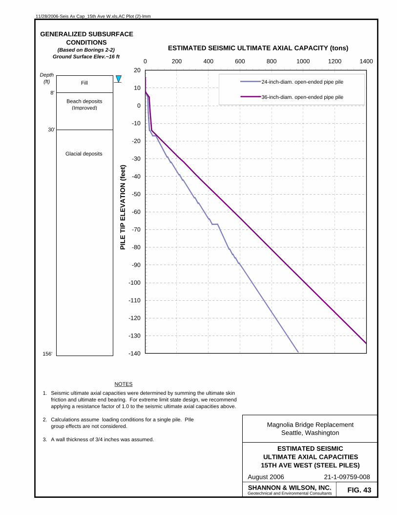
11/28/2006-Seis Ax Cap_15th Ave W.xls,AC Plot (2)-lmm
FIG. 43
ESTIMATED SEISMICULTIMATE AXIAL CAPACITIES
15TH AVE WEST (STEEL PILES)
Magnolia Bridge ReplacementSeattle, Washington
August 2006 21-1-09759-008
-140
-130
-120
-110
-100
-90
-80
-70
-60
-50
-40
-30
-20
-10
0
10
200 200 400 600 800 1000 1200 1400
ESTIMATED SEISMIC ULTIMATE AXIAL CAPACITY (tons)
PILE
TIP
ELE
VATI
ON
(fee
t)
24-inch-diam. open-ended pipe pile
36-inch-diam. open-ended pipe pile
SHANNON & WILSON, INC.Geotechnical and Environmental Consultants
NOTES
1.
2.
3.
Seismic ultimate axial capacities were determined by summing the ultimate skin friction and ultimate end bearing. For extreme limit state design, we recommend applying a resistance factor of 1.0 to the seismic ultimate axial capacities above.
Calculations assume loading conditions for a single pile. PIle group effects are not considered.
A wall thickness of 3/4 inches was assumed.
Fill
8'
GENERALIZED SUBSURFACECONDITIONS
(Based on Borings 2-2)Ground Surface Elev.~16 ft
30'
Beach deposits(Improved)
Glacial deposits
Depth (ft)
156'

11/28/2006-Seis Ax Cap_15th Ave W.xls,Uplift-lmm
FIG. 44
ESTIMATED SEISMICULTIMATE UPLIFT CAPACITIES
15TH AVE WEST
Magnolia Bridge ReplacementSeattle, Washington
August 2006 21-1-09759-008
-140
-130
-120
-110
-100
-90
-80
-70
-60
-50
-40
-30
-20
-10
0
10
200 500 1000 1500 2000 2500 3000 3500 4000
ESTIMATED SEISMIC ULTIMATE UPLIFT CAPACITY (tons)
PILE
TIP
/ SH
AFT
BA
SE E
LEVA
TIO
N (f
eet)
4-ft-diam. drilled shaft
6-ft-diam. drilled shaft
8-ft-diam. drilled shaft
10-ft-diam. drilled shaft
24-inch-diam. open-ended pipe pile
36-inch-diam. open-ended pipe pile
SHANNON & WILSON, INC.Geotechnical and Environmental Consultants
NOTES
1.
2.
For extreme limit state design, we recommend applying a resistance factor of 1.0 to the seismic ultimate uplift capacities above.
Calculations assume loading conditions for a single pile/ shaft. Pile/shaft group effects are not considered.
GENERALIZED SUBSURFACECONDITIONS
(Based on Borings 2-2)Ground Surface Elev.~16 ft
Depth (ft) Fill
8'
30'
Beach deposits(Improved)
Glacial deposits
156'
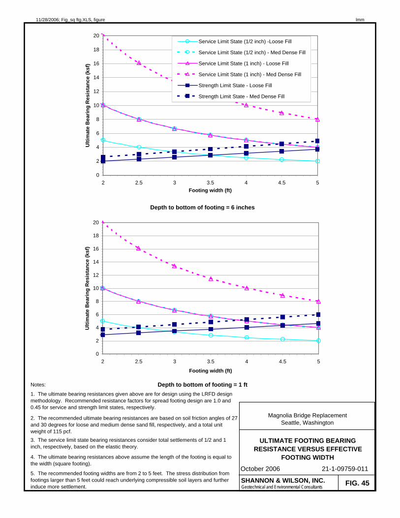
11/28/2006; Fig_sq ftg.XLS, figure lmm
Notes:
5. The recommended footing widths are from 2 to 5 feet. The stress distribution from footings larger than 5 feet could reach underlying compressible soil layers and further induce more settlement.
4. The ultimate bearing resistances above assume the length of the footing is equal to the width (square footing).
Depth to bottom of footing = 1 ft1. The ultimate bearing resistances given above are for design using the LRFD design methodology. Recommended resistance factors for spread footing design are 1.0 and 0.45 for service and strength limit states, respectively.
Magnolia Bridge ReplacementSeattle, Washington
ULTIMATE FOOTING BEARING RESISTANCE VERSUS EFFECTIVE
FOOTING WIDTH
21-1-09759-011
FIG. 45
October 2006
2. The recommended ultimate bearing resistances are based on soil friction angles of 27 and 30 degrees for loose and medium dense sand fill, respectively, and a total unit weight of 115 pcf.3. The service limit state bearing resistances consider total settlements of 1/2 and 1 inch, respectively, based on the elastic theory.
Depth to bottom of footing = 6 inches
0
2
4
6
8
10
12
14
16
18
20
2 2.5 3 3.5 4 4.5 5Footing width (ft)
Ulti
mat
e B
earin
g R
esis
tanc
e (k
sf)
Service Limit State (1/2 inch) -Loose Fill
Service Limit State (1/2 inch) - Med Dense Fill
Service Limit State (1 inch) - Loose Fill
Service Limit State (1 inch) - Med Dense Fill
Strength Limit State - Loose Fill
Strength Limit State - Med Dense Fill
SHANNON & WILSON, INC.Geotechnical and Environmental Consultants
0
2
4
6
8
10
12
14
16
18
20
2 2.5 3 3.5 4 4.5 5
Footing width (ft)
Ulti
mat
e B
earin
g R
esis
tanc
e (k
sf)