formal verification in industrial setting
TRANSCRIPT

Verilog HDLVerilogVerilog HDLHDL
Pallab Pallab DasguptaDasguptaProfessor, Dept. of Computer Science & Professor, Dept. of Computer Science & EnggEngg.,.,ProfessorProfessor--inin--charge, AVLSI Design Lab,charge, AVLSI Design Lab,Indian Institute of Technology KharagpurIndian Institute of Technology Kharagpur
Testing & VerificationDept. of Computer Science & Engg, IIT KharagpurTesting & VerificationTesting & VerificationDept. of Computer Science & Dept. of Computer Science & EnggEngg, IIT Kharagpur, IIT Kharagpur

AgendaAgenda
Structural Hardware ModelsStructural Hardware Models44--Valued LogicValued LogicDelayDelayInstantiationInstantiationWiringWiringTest BenchesTest BenchesBehavioral ModelsBehavioral ModelsConcurrencyConcurrencySummarySummary
Source: The Verilog Hardware Description Language,
By Thomas and Moorby, Kluwer Academic Publishers

3Dept. of Computer Sc & Dept. of Computer Sc & EnggEngg, IIT Kharagpur, IIT Kharagpur
Representation: Structural ModelsRepresentation: Structural ModelsStructural modelsStructural models■■ Are built from gate primitives and/or other modulesAre built from gate primitives and/or other modules■■ They describe the circuit using logic gates They describe the circuit using logic gates —— much as you much as you
would see in an implementation of a circuit.would see in an implementation of a circuit.
Identify:Identify:■■ Gate instances, wire names, delay from Gate instances, wire names, delay from aa or or bb to to ff..■■ This is a This is a multiplexormultiplexor —— it selects one of n inputs (2 here) and it selects one of n inputs (2 here) and
passes it on to the outputpasses it on to the outputmodule MUX (f, a, b, sel);output f;input a, b, sel;
and #5 g1 (f1, a, nsel),g2 (f2, b, sel);
or #5 g3 (f, f1, f2);not g4 (nsel, sel);
endmodule
a
bf
sel
f = a • sel’ + b • sel
a
bf
sel
nsel
f2
f1

4Dept. of Computer Sc & Dept. of Computer Sc & EnggEngg, IIT Kharagpur, IIT Kharagpur
Representation: GateRepresentation: Gate--Level ModelsLevel ModelsNeed to model the gateNeed to model the gate’’s:s:■■ FunctionFunction■■ DelayDelay
FunctionFunction■■ Generally, Generally, HDLsHDLs have builthave built--in gatein gate--level primitives level primitives
●● Verilog has NAND, NOR, AND, OR, XOR, XNOR, BUF, Verilog has NAND, NOR, AND, OR, XOR, XNOR, BUF, NOT, and some othersNOT, and some others
■■ The gates operate on input values producing an output valueThe gates operate on input values producing an output value●● Typical Verilog gate instantiation is:Typical Verilog gate instantiation is:
and #delay instanceand #delay instance--name (out, in1, in2, in3, name (out, in1, in2, in3, ……););
and #5and #5 g1 (f1, a, g1 (f1, a, nselnsel););
optional “many”
a comma here let’s you list other instance names and their port lists.
a comma here let’s you list other instance names and their port lists.

5Dept. of Computer Sc & Dept. of Computer Sc & EnggEngg, IIT Kharagpur, IIT Kharagpur
FourFour--Valued LogicValued Logic
Verilog Logic ValuesVerilog Logic Values■■ The underlying data representation allows for any bit to have The underlying data representation allows for any bit to have
one of four valuesone of four values■■ 1, 0, x (unknown), z (high impedance)1, 0, x (unknown), z (high impedance)■■ x x —— one of: 1, 0, z, or in the state of changeone of: 1, 0, z, or in the state of change■■ z z —— the high impedance output of a trithe high impedance output of a tri--state gate.state gate.

6Dept. of Computer Sc & Dept. of Computer Sc & EnggEngg, IIT Kharagpur, IIT Kharagpur
FourFour--Valued LogicValued LogicWhat basis do these have in reality?What basis do these have in reality?■■ 0, 1 0, 1 …… no questionno question■■ zz …… A A tritri--statestate gate drives either a zero or one on its output gate drives either a zero or one on its output
……and if itand if it’’s not doing that, its output is high impedance (z). s not doing that, its output is high impedance (z). TriTri--state gates are real devices and z is a state gates are real devices and z is a realreal electrical affect.electrical affect.
■■ x x …… not a real value. There is no not a real value. There is no realreal gate that drives an x on gate that drives an x on to a wire. x is used as a to a wire. x is used as a debuggingdebugging aid. x means the simulator aid. x means the simulator cancan’’t determine the answer and so maybe you should worry! t determine the answer and so maybe you should worry! All values in a simulation start as x.All values in a simulation start as x.
BTW BTW ……■■ Verilog keeps track of more values than these in some Verilog keeps track of more values than these in some
situations. situations.

7Dept. of Computer Sc & Dept. of Computer Sc & EnggEngg, IIT Kharagpur, IIT Kharagpur
FourFour--Valued LogicValued Logic
Logic with multiLogic with multi--level logic valueslevel logic values■■ Logic with these four values make senseLogic with these four values make sense
●● NandNand anything with a 0, and you get a 1. This includes anything with a 0, and you get a 1. This includes having an x or z on the other input. Thathaving an x or z on the other input. That’’s the nature of s the nature of the the nandnand gategate
●● NandNand two two xx’’ss and you get an x and you get an x —— makes sense!makes sense!■■ Note: z treated as an x on input. Their rows and columns are Note: z treated as an x on input. Their rows and columns are
the samethe same■■ If you forget to connect an input If you forget to connect an input …… it will be seen as an z.it will be seen as an z.■■ At the start of simulation, At the start of simulation, everythingeverything is an x.is an x.
NandNand 00 11 xx zz00 11 11 11 1111 11 00 xx xxxx 11 xx xx xxzz 11 xx xx xx
A 4A 4--valued truth table for a valued truth table for a NandNand gate with two inputsgate with two inputs
Inpu
t AIn
put A
Input BInput B AABB

8Dept. of Computer Sc & Dept. of Computer Sc & EnggEngg, IIT Kharagpur, IIT Kharagpur
DelayDelayTransportTransport delaydelay —— input to output delayinput to output delay■■ ““nandnand #35 (f1, a, b, c);#35 (f1, a, b, c);”” #35 is the transport delay#35 is the transport delay
What if the input changes during that time?What if the input changes during that time?■■ i.e., how wide must an input spike be to affect the output?i.e., how wide must an input spike be to affect the output?■■ Think of the gate as having inertia. Think of the gate as having inertia. —— The input change must The input change must
be present long enough to get the output to change. (That be present long enough to get the output to change. (That ““long enoughlong enough”” time is called time is called inertialinertial delay)delay)
■■ in Verilog, this time is equal to the transport delayin Verilog, this time is equal to the transport delay
ab c
τ — transport delay
ab c
ab c
pulse too small, no
output change

9Dept. of Computer Sc & Dept. of Computer Sc & EnggEngg, IIT Kharagpur, IIT Kharagpur
Let’s Build a Wider 2Let’s Build a Wider 2--bit MUXbit MUXBuild a 2Build a 2--bit 2:1 MUXbit 2:1 MUX■■ OK, letOK, let’’s put two 1s put two 1--bit 2:1 bit 2:1 MUXesMUXes in the same module with in the same module with
a common select linea common select line■■ What would it look like?What would it look like?
f1
f0a0
a1
b0
b1
sel
a
b
sel
f

10Dept. of Computer Sc & Dept. of Computer Sc & EnggEngg, IIT Kharagpur, IIT Kharagpur
Reuse!Reuse!
Reuse of smaller objectsReuse of smaller objects■■ Can we use the MUX module that we already designed? Can we use the MUX module that we already designed? ■■ A big idea A big idea —— instantiationinstantiation■■ Modules and primitive gates can be Modules and primitive gates can be instantiatedinstantiated —— copied copied
—— to many sites in a designto many sites in a design■■ Previously, two Previously, two ANDsANDs, one OR, and a NOT gate were , one OR, and a NOT gate were
instantiated into module MUXinstantiated into module MUX■■ Now we instantiate two copies of module MUX into module Now we instantiate two copies of module MUX into module
wideMuxwideMux
module wideMux (f1, f0, a1, a0, b1, b0, sel);input a1, a0, b1, b0, sel;output f1, f0;
MUX bit1 (f1, a1, b1, sel),bit0 (f0, a0, b0, sel);
endmodule
Instantiate two MUX modules, name them, and specify connections (the order is important).

11Dept. of Computer Sc & Dept. of Computer Sc & EnggEngg, IIT Kharagpur, IIT Kharagpur
Instantiation Instantiation —— CopiesCopies
Modules and gate primitives are Modules and gate primitives are instantiatedinstantiated == == copiedcopied
■■ Note the word Note the word ““copiescopies””
●● The copies (also called The copies (also called instancesinstances) share the module (or ) share the module (or primitive) definitionprimitive) definition
●● If we ever change a module definition, the copies will all If we ever change a module definition, the copies will all change toochange too
●● However, the internal entities (gate names, internal port However, the internal entities (gate names, internal port names, and other things to come) are all private, separate names, and other things to come) are all private, separate copiescopies

12Dept. of Computer Sc & Dept. of Computer Sc & EnggEngg, IIT Kharagpur, IIT Kharagpur
Instantiation Instantiation —— CopiesCopies
Modules and gate primitives are Modules and gate primitives are instantiatedinstantiated == == copiedcopied■■ DonDon’’tt think of module instantiations as subroutines that are think of module instantiations as subroutines that are
calledcalled●● They are They are copiescopies —— there are 2 MUX modules in there are 2 MUX modules in wideMuxwideMux
with a total of:with a total of:
______ AND gates, ______ AND gates,
______ OR gates, ______ OR gates,
______ NOT gates______ NOT gates
4
2
2

13Dept. of Computer Sc & Dept. of Computer Sc & EnggEngg, IIT Kharagpur, IIT Kharagpur
Why Is This Cool?Why Is This Cool?
In VerilogIn Verilog■■ ““PrimitivePrimitive”” gates are predefined (NAND, NOR, gates are predefined (NAND, NOR, ……) ) ■■ Other modules are built by instantiating these gatesOther modules are built by instantiating these gates■■ Other modules are built by instantiating other modules, Other modules are built by instantiating other modules, ……
The design The design hierarchyhierarchy of modules is built using instantiationof modules is built using instantiation■■ Bigger modules of useful functionality are definedBigger modules of useful functionality are defined■■ You can then design with these bigger modulesYou can then design with these bigger modules
●● You can reuse modules that youYou can reuse modules that you’’ve already built and testedve already built and tested●● You can hide the detail You can hide the detail —— why show a bunch of gates and why show a bunch of gates and
their interconnection when you know ittheir interconnection when you know it’’s a s a muxmux! !
Instantiation & hierarchy control complexity. Instantiation & hierarchy control complexity. ■■ No one designs 1M+ random gates No one designs 1M+ random gates —— they use hierarchy. they use hierarchy. ■■ What are the software analogies?What are the software analogies?

14Dept. of Computer Sc & Dept. of Computer Sc & EnggEngg, IIT Kharagpur, IIT Kharagpur
How to Wire Modules TogetherHow to Wire Modules TogetherReal designs have many modules and gatesReal designs have many modules and gates
module bbb (i1, i2, o1, clk);input i1, i2, clk;output o1;
xor (o1, i2, …);…
module aaa (in1, out1, out2);input in1;output out1, out2;
…
nand #2 (out1, in1, b);nand #6 (out2, in1, b);…
module putTogether ();wire w1, w2, w3, w4;
bbb lucy (w1, w2, w3, w4);aaa ricky (w3, w2, w1);
…what happens when out1 is set to 1?
Each module has it’s own namespace. Wires connect elements of namespaces.
Each module has it’s own namespace. Wires connect elements of namespaces.

15Dept. of Computer Sc & Dept. of Computer Sc & EnggEngg, IIT Kharagpur, IIT Kharagpur
Implicit WiresImplicit WiresHow come there were no wires declared in some of these How come there were no wires declared in some of these modules?modules?■■ GateGate instantiations implicitly declare wires for their outputs.instantiations implicitly declare wires for their outputs.■■ AllAll otherother connections must be connections must be explicitly declared as wires explicitly declared as wires ——
for instance, connections between module portsfor instance, connections between module ports■■ OutputOutput and and inputinput declarations are wiresdeclarations are wires
module putTogether ();wire w1, w2, w3, w4;
mux inst1 (w1, w2, w3, w4);aaa duh (w3, w2, w1);
…
module mux (f, a, b, sel);output f;input a, b, sel;
and #5 g1 (f1, a, nsel),g2 (f2, b, sel);
or #5 g3 (f, f1, f2);not g4 (nsel, sel);
endmodule
wires implicitly declared (f1, f2, nsel)
wires explicitly declared

16Dept. of Computer Sc & Dept. of Computer Sc & EnggEngg, IIT Kharagpur, IIT Kharagpur
How to Build and Test a ModuleHow to Build and Test a Module
Construct a Construct a ““test benchtest bench”” for your designfor your design■■ Develop your hierarchical system within a module that has Develop your hierarchical system within a module that has
input and output ports (called input and output ports (called ““designdesign”” here)here)■■ Develop a separate module to generate tests for the module Develop a separate module to generate tests for the module
((““testtest””))■■ Connect these together within another module (Connect these together within another module (““testbenchtestbench””))
module design (a, b, c);input a, b;output c;…
module test (q, r);output q, r;
initial begin//drive the outputs with signals…
module testbench ();wire l, m, n;
design d (l, m, n);test t (l, m);
initial begin//monitor and display…
17Dept. of Computer Sc & Dept. of Computer Sc & EnggEngg, IIT Kharagpur, IIT Kharagpur
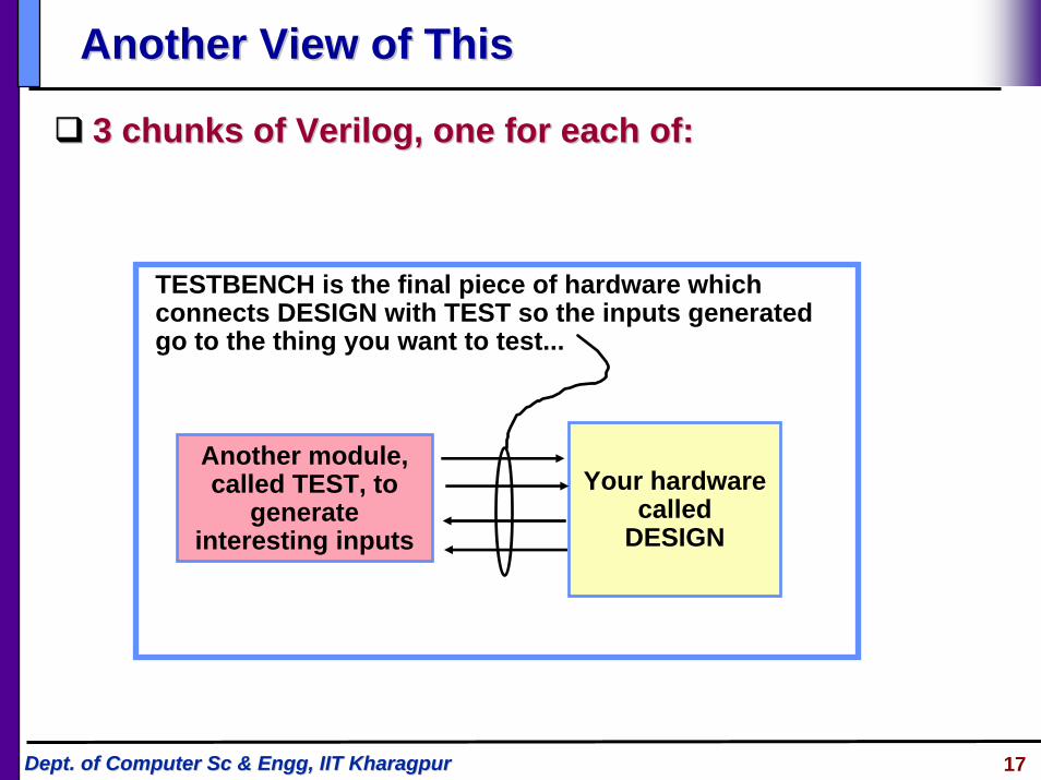
Another View of ThisAnother View of This
3 chunks of Verilog, one for each of:3 chunks of Verilog, one for each of:
Your hardwarecalled
DESIGN
TESTBENCH is the final piece of hardware whichconnects DESIGN with TEST so the inputs generatedgo to the thing you want to test...
Another module, called TEST, to
generate interesting inputs

18Dept. of Computer Sc & Dept. of Computer Sc & EnggEngg, IIT Kharagpur, IIT Kharagpur
An ExampleAn ExampleModule Module testAddtestAdd generated inputs for module generated inputs for module halfAddhalfAdd and displayed and displayed
changes. Module changes. Module halfAddhalfAdd was the was the designdesign
module tBench;wire su, co, a, b;
halfAdd ad (su, co, a, b);testAdd tb (a, b, su, co);
endmodule
module halfAdd (sum, cOut, a, b); output sum, cOut;input a, b;
xor #2 (sum, a, b);and #2 (cOut, a, b);
endmodule
module testAdd (a, b, sum, cOut);input sum, cOut;output a, b;reg a, b;
initial begin$monitor ($time,,
“a=%b, b=%b, sum=%b, cOut=%b”,a, b, sum, cOut);
a = 0; b = 0;#10 b = 1;#10 a = 1;#10 b = 0;#10 $finish;
endendmodule

19Dept. of Computer Sc & Dept. of Computer Sc & EnggEngg, IIT Kharagpur, IIT Kharagpur
The Test ModuleThe Test ModuleItIt’’s the test generators the test generator$monitor $monitor ■■ prints its string when executed. prints its string when executed. ■■ after that, the string is printed after that, the string is printed
when one of the listed values when one of the listed values changes.changes.
■■ only one monitor can be active at only one monitor can be active at any timeany time
■■ prints at end of current simulation prints at end of current simulation timetime
Function of this testerFunction of this tester■■ at time zero, print values and set at time zero, print values and set
a=b=0a=b=0■■ after 10 time units, set b=1after 10 time units, set b=1■■ after another 10, set a=1 after another 10, set a=1 ■■ after another 10 set b=0after another 10 set b=0■■ then another 10 and finishthen another 10 and finish
module testAdd(a, b, sum, cOut);input sum, cOut;output a, b;reg a, b;
initial begin$monitor ($time,,
“a=%b, b=%b, sum=%b, cOut=%b”,
a, b, sum, cOut);a = 0; b = 0;#10 b = 1;#10 a = 1;#10 b = 0;#10 $finish;
endendmodule

20Dept. of Computer Sc & Dept. of Computer Sc & EnggEngg, IIT Kharagpur, IIT Kharagpur
Another Version of a Test ModuleAnother Version of a Test Module
MultiMulti--bit bit ““thingiesthingies””■■ test is a twotest is a two--bit register bit register
and outputand output■■ It acts as a twoIt acts as a two--bit bit
number (counts 00number (counts 00--0101--1010--1111--0000……))
■■ Module Module tBenchtBench needs to needs to connect it correctly connect it correctly ——mod mod halfAddhalfAdd has 1has 1--bit bit ports.ports.
module testAdd (test, sum, cOut);input sum, cOut;output [1:0] test;reg [1:0] test;
initial begin$monitor ($time,,
"test=%b, sum=%b, cOut=%b",test, sum, cOut);
test = 0;#10 test = test + 1;#10 test = test + 1;#10 test = test + 1;#10 $finish;
endendmodule
module tBench;wire su, co;wire [1:0] t;
halfAdd ad (su, co, t[1], t[0]);testAdd tb (t, su, co);
endmoduleConnects bit 0 or wire t to this port (b of the module halfAdder)

21Dept. of Computer Sc & Dept. of Computer Sc & EnggEngg, IIT Kharagpur, IIT Kharagpur
Another Version of Another Version of testAddtestAdd
Other procedural Other procedural statementsstatements■■ You can use You can use ““forfor””, ,
““whilewhile””, , ““ifif--thenthen--elseelse”” and others and others here.here.
■■ This makes it easier This makes it easier to write if you have to write if you have lots of input bits.lots of input bits.
module tBench;wire su, co;wire [1:0] t;
halfAdd ad (su, co, t[1], t[0]);testAdd tb (t, su, co);
endmodule
module testAdd (test, sum, cOut);input sum, cOut;output [1:0] test;reg [1:0] test;
initial begin$monitor ($time,,
"test=%b, sum=%b, cOut=%b",test, sum, cOut);
for (test = 0; test < 3; test = test + 1)#10;
#10 $finish;end
endmodule
hmm… “<3” … ?

22Dept. of Computer Sc & Dept. of Computer Sc & EnggEngg, IIT Kharagpur, IIT Kharagpur
Structural Vs. Behavioral ModelsStructural Vs. Behavioral Models
Structural modelStructural model■■ Just specifies primitive gates and wiresJust specifies primitive gates and wires■■ i.e., the structure of a logical i.e., the structure of a logical netlistnetlist■■ You basically know how to do this now.You basically know how to do this now.
Behavioral modelBehavioral model■■ More like a procedure in a programming languageMore like a procedure in a programming language■■ Still specify a module in Verilog with inputs and outputs...Still specify a module in Verilog with inputs and outputs...■■ ...but inside the module you write code to tell what you want t...but inside the module you write code to tell what you want to o
have happen, NOT what gates to connect to make it happenhave happen, NOT what gates to connect to make it happen■■ i.e., you specify the behavior you want, not the structure to doi.e., you specify the behavior you want, not the structure to do itit
Why use behavioral modelsWhy use behavioral models■■ For For testbenchtestbench modules to test structural designsmodules to test structural designs■■ For highFor high--level specs to drive logic synthesis toolslevel specs to drive logic synthesis tools

23Dept. of Computer Sc & Dept. of Computer Sc & EnggEngg, IIT Kharagpur, IIT Kharagpur
How Do Behavioral Models Fit In?How Do Behavioral Models Fit In?How do they work with the event list How do they work with the event list and scheduler?and scheduler?■■ Initial (and always) begin Initial (and always) begin
executing at time 0 in arbitrary executing at time 0 in arbitrary orderorder
■■ They execute until they come to They execute until they come to a a ““#delay#delay”” operatoroperator
■■ They then suspend, putting They then suspend, putting themselves in the event list 10 themselves in the event list 10 time units in the future (for the time units in the future (for the case at the right)case at the right)
■■ At 10 time units in the future, At 10 time units in the future, they resume executing where they resume executing where they left off.they left off.
Some details omittedSome details omitted■■ ...more to come...more to come
module testAdd (a, b, sum, cOut);input sum, cOut;output a, b;reg a, b;
initial begin$monitor ($time,,
“a=%b, b=%b, sum=%b, cOut=%b”,a, b, sum, cOut);
a = 0; b = 0;#10 b = 1;#10 a = 1;#10 b = 0;#10 $finish;
endendmodule

24Dept. of Computer Sc & Dept. of Computer Sc & EnggEngg, IIT Kharagpur, IIT Kharagpur
Concurrent ActivityConcurrent Activity
Do these two evaluations happen at the same time?Do these two evaluations happen at the same time?■■ Yes and No!Yes and No!
Yes Yes ……■■ They happen at the same They happen at the same simulatedsimulated (or virtual) time(or virtual) time■■ After all, the time when they occur is 27After all, the time when they occur is 27
No No ……■■ We all know the processor is only doing one thing at any We all know the processor is only doing one thing at any
given timegiven time
So, which is done first?So, which is done first?■■ ThatThat’’s undefined. We cans undefined. We can’’t assume anything except that the t assume anything except that the
order is arbitrary.order is arbitrary.
Eval g2, g3Eval g2, g3
Yes and No!

25Dept. of Computer Sc & Dept. of Computer Sc & EnggEngg, IIT Kharagpur, IIT Kharagpur
Concurrent ActivityConcurrent Activity
The point isThe point is■■ In the real implementation, all activity will be concurrentIn the real implementation, all activity will be concurrent■■ Thus the simulator models the elements of the system as Thus the simulator models the elements of the system as
being concurrent in simulated timebeing concurrent in simulated time●● The simulator stands on its head trying to do this!The simulator stands on its head trying to do this!
Thus,Thus,■■ Even though the simulator executes each element of the Even though the simulator executes each element of the
design one at a time design one at a time ……■■ …… wewe’’ll call it concurrentll call it concurrent

26Dept. of Computer Sc & Dept. of Computer Sc & EnggEngg, IIT Kharagpur, IIT Kharagpur
Behavioral Behavioral VerilogVerilog HDL codesHDL codes
module module module_namemodule_name(port_names(port_names););
input [input [port_sizeport_size] ] input_port_namesinput_port_names;;
output [output [port_sizeport_size] ] output_port_namesoutput_port_names;;
wire [wire [wire_sizewire_size] ] wire_nameswire_names;;
regreg [[reg_sizereg_size] ] reg_namesreg_names;;
always @(sensitivity list)always @(sensitivity list)
-- -- -- --
behavioral statementsbehavioral statements
-- -- -- --
endmoduleendmodule
MultiplexerMultiplexermodule module muxmux (f, a, b, (f, a, b, selsel););input [3:0] a, b;input [3:0] a, b;input input selsel;;output [3:0] f;output [3:0] f;regreg [3:0] f;[3:0] f;always @(a or b or always @(a or b or selsel))if (if (selsel))
f=b;f=b;elseelse
f=a;f=a;endmoduleendmodule

27Dept. of Computer Sc & Dept. of Computer Sc & EnggEngg, IIT Kharagpur, IIT Kharagpur
FlipFlip--flop Design: flop Design: An ExampleAn Example
module module DFF(dDFF(d, q, , q, qbarqbar, , clkclk, reset);, reset);input d, input d, clkclk, reset;, reset;output q, output q, qbarqbar;;regreg q, q, qbarqbar;;
always @(always @(posedgeposedge clkclk or or posedgeposedge reset)reset)beginbeginif (if (selsel))
begin q = 1begin q = 1’’b0; b0; qbarqbar = 1= 1’’b1; endb1; endelseelse
begin q = d; begin q = d; qbarqbar = ~d; end= ~d; endendend
endmoduleendmodule

28Dept. of Computer Sc & Dept. of Computer Sc & EnggEngg, IIT Kharagpur, IIT Kharagpur
Behavioral StatementsBehavioral Statements
Continuous assignment statements Continuous assignment statements ■■ using using assignassign
Procedural assignment statementsProcedural assignment statements■■ Blocking assignment (using =)Blocking assignment (using =)■■ Non blocking assignment (using <=)Non blocking assignment (using <=)

29Dept. of Computer Sc & Dept. of Computer Sc & EnggEngg, IIT Kharagpur, IIT Kharagpur
Blocks StatementsBlocks Statements
Sequential Block Statements:Sequential Block Statements:■■ Sequential block is a group of statements between a Sequential block is a group of statements between a beginbegin
and an and an endend..■■ A sequential block, in an A sequential block, in an alwaysalways statement executes statement executes
repeatedlyrepeatedly■■ Inside an Inside an initial initial statement, it operates only oncestatement, it operates only once
Parallel Block Statements:Parallel Block Statements:■■ Statements are enclosed withinStatements are enclosed within
forkfork----------------joinjoin

30Dept. of Computer Sc & Dept. of Computer Sc & EnggEngg, IIT Kharagpur, IIT Kharagpur
Block statements: Block statements: ExamplesExamples
always @(a or b or c);always @(a or b or c);beginbegin#5 d = #5 d = a+ba+b;;#10 e = a#10 e = a--c;c;#15 f = #15 f = b+cb+c;;endend
initialinitialbeginbegin#5 d = #5 d = a+ba+b;;#10 e = a#10 e = a--c;c;#15 f = #15 f = b+cb+c;;endend
always @(a or b or c);always @(a or b or c);forkfork#5 d = #5 d = a+ba+b;;#10 e = a#10 e = a--c;c;#15 f = #15 f = b+cb+c;;joinjoin

31Dept. of Computer Sc & Dept. of Computer Sc & EnggEngg, IIT Kharagpur, IIT Kharagpur
ExamplesExamplesBlocking:Blocking:
always @(A1 or B1 or C1 or M1)always @(A1 or B1 or C1 or M1)beginbegin
M1 = #3 (A1 & B1);M1 = #3 (A1 & B1);Y1 = #1 (M1 | C1);Y1 = #1 (M1 | C1);
endend
NonNon--blocking:blocking:always @(A2 or B2 or C2 or M2)always @(A2 or B2 or C2 or M2)beginbegin
M2 <= #3 (A2 & B2);M2 <= #3 (A2 & B2);Y2 <= #1 (M1 | C1);Y2 <= #1 (M1 | C1);
endend
Statement executed at time t Statement executed at time t causing M1 to be assigned at t+3causing M1 to be assigned at t+3
Statement executed at time t+3 Statement executed at time t+3 causing Y1 to be assigned at time causing Y1 to be assigned at time t+4t+4
Statement executed at time t Statement executed at time t causing M2 to be assigned at t+3causing M2 to be assigned at t+3
Statement executed at time t Statement executed at time t causing Y2 to be assigned at time causing Y2 to be assigned at time t+1. Uses old values.t+1. Uses old values.
32Dept. of Computer Sc & Dept. of Computer Sc & EnggEngg, IIT Kharagpur, IIT Kharagpur
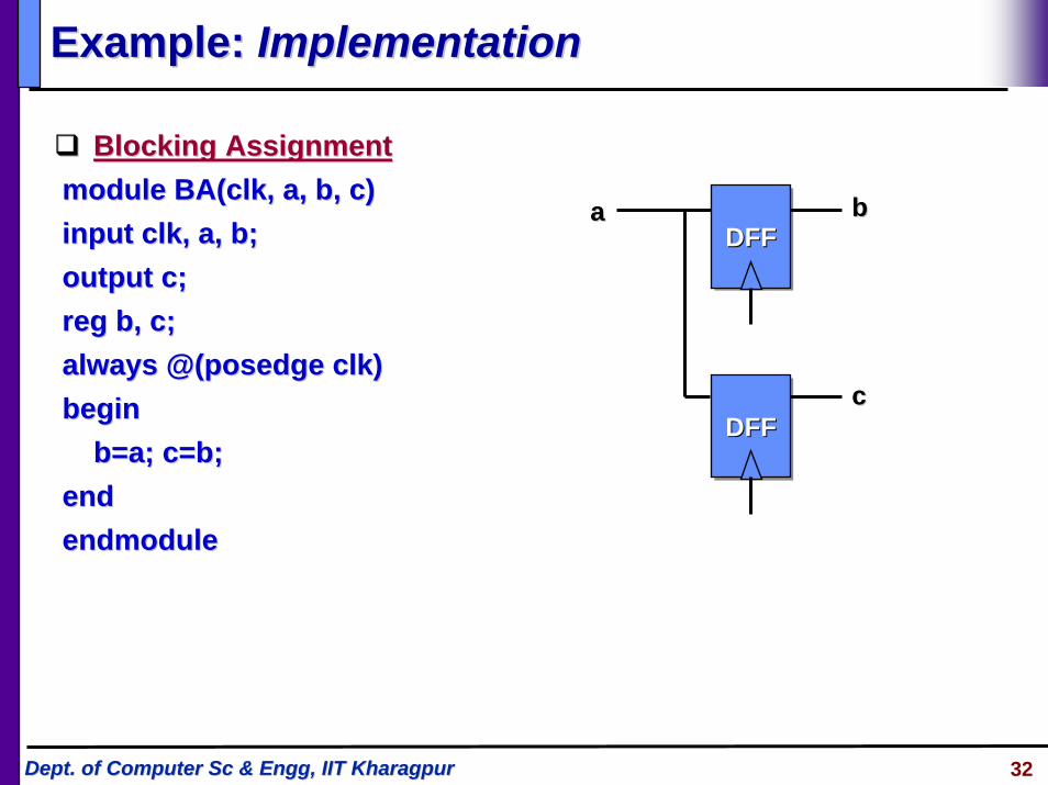
Example: Example: ImplementationImplementation
Blocking AssignmentBlocking Assignmentmodule module BA(clkBA(clk, a, b, c), a, b, c)input input clkclk, a, b;, a, b;output c;output c;regreg b, c;b, c;always @(always @(posedgeposedge clkclk))beginbegin
b=a; c=b;b=a; c=b;endendendmoduleendmodule
DFFDFFDFF
DFFDFFDFF
aa bb
cc

33Dept. of Computer Sc & Dept. of Computer Sc & EnggEngg, IIT Kharagpur, IIT Kharagpur
Example: Example: ImplementationImplementation
Non Blocking AssignmentNon Blocking Assignmentmodule module NBA(clkNBA(clk, a, b, c), a, b, c)input input clkclk, a, b;, a, b;output c;output c;regreg b, c;b, c;always @(always @(posedgeposedge clkclk))beginbegin
b<=a; c<=b;b<=a; c<=b;endendendmoduleendmodule
DFFDFFDFF
DFFDFFDFF
aa bb
cc

34Dept. of Computer Sc & Dept. of Computer Sc & EnggEngg, IIT Kharagpur, IIT Kharagpur
Design using Functions and TasksDesign using Functions and TasksFunctionFunction
module module m_namem_name( ( port_declarationsport_declarations))------beginbegin------ret_valret_val = = func_name(argumentsfunc_name(arguments););endend
function function func_namefunc_name;;input declarationinput declarationvariable declarationvariable declarationbeginbegin<statements><statements>
endendendfunctionendfunction
endmoduleendmodule
TaskTaskmodule module m_namem_name( ( port_declarationsport_declarations))------beginbegin------task_name(argumentstask_name(arguments););endend
task task task_nametask_name;;input declarationinput declarationoutput declarationoutput declarationvariable declarationvariable declarationbeginbegin<statements><statements>
endendendtaskendtaskendmoduleendmodule

35Dept. of Computer Sc & Dept. of Computer Sc & EnggEngg, IIT Kharagpur, IIT Kharagpur
FSM Design using FSM Design using VerilogVerilog HDLHDLmodule parity (module parity (clkclk, reset, i, o) ;, reset, i, o) ;input input clkclk, reset, i;, reset, i;output 0;output 0;regreg stst, , next_stnext_st, o;, o;parameter parameter st_evenst_even = 0, = 0, st_oddst_odd = 1;= 1;always @ (always @ (posedgeposedge clkclk or or posedgeposedge reset)reset)beginbegin
if (reset == 1) if (reset == 1) stst <= <= st_evenst_even;;
else else stst <= <= next_stnext_st;;
endend/* State transitions *//* State transitions *//* Output computation *//* Output computation */endmoduleendmodule
Even/0
Odd/1
i = 1 i = 1
Reset

36Dept. of Computer Sc & Dept. of Computer Sc & EnggEngg, IIT Kharagpur, IIT Kharagpur
State Transitions & O/P computationsState Transitions & O/P computations// State Transitions// State Transitionsalways @ (i or always @ (i or stst))beginbegin
if (i==1) beginif (i==1) beginif (if (stst == == st_evenst_even))next_stnext_st = = st_oddst_odd;;
else else next_stnext_st = = st_evenst_even;;endendelse else next_stnext_st = = stst;;
endend// Output Computation// Output Computationalways @(always @(stst))beginbegin
if (if (stst == == st_evenst_even) o=0;) o=0;else o=1;else o=1;
endend
Even/0
Odd/1
i = 1 i = 1
Reset