form 150.68-eg1.en.ce (0911)yorkrussia.ru/files/inzhenepnoe_rykovodstvo_ylpa.pdf · engineering...
TRANSCRIPT
ENGINEERING GUIDE
YLPA0340SE-YLPA0610SE YLPA0355HE-YLPA0640HE
Revision 1 FORM 150.68-EG1.EN.CE (0911)
REVERSE CYCLE AIR TO WATER HEAT PUMPSWITH SCROLL COMPRESSORS
STYLE ACooling Capacities: 342 kW to 647 kWHeating Capacities: 351 kW to 666 kW
R410A

2 EN
All data in this document is subject to change without prior notice.
Table of Contents
Nominal Data. ... ... ... ... ... ... ... ... ... ... ... ... 2
Specifi cation .. ... ... ... ... ... ... ... ... ... ... ... ... 3
Accessories and Options ... ... ... ... ... ... ... ... ... 4
Refrigerant Flow Block Diagrams ... ... ... ... ... ... 6
Component Location Diagrams ... ... ... ... ... ... ... 7
Application Data . ... ... ... ... ... ... ... ... ... ... ... 8
Pipework Arrangement . ... ... ... ... ... ... ... ... .. 10
Electrical Connection ... ... ... ... ... ... ... ... ... ...11
Connection Diagram ... ... ... ... ... ... ... ... ... .. 13
Refrigerant to Water Heat Exchanger Pressure Drop Graph... ... ... ... ... ... ... ... ... ... ... ... ... ... .. 14
Operating Limitations ... ... ... ... ... ... ... ... ... .. 14
Physical Data. ... ... ... ... ... ... ... ... ... ... ... .. 15
Fan Data ... ... ... ... ... ... ... ... ... ... ... ... ... .. 16
Nominal DataYLPA Model 0355HE 0425HE 0505HE 0570HE 0640HE
Capacity kW (1) 359 444 526 590 647
EER (2) 3.26 3.24 3.23 3.11 3.02
Eurovent Class A A A A B
ESEER (3) 4.50 4.50 4.60 4.4 4.4
Capacity kW (4) 369 460 554 600 666
EER (4) 3.27 3.22 3.20 3.24 3.23
Eurovent Class A A A A A
Sound Pressure at 10 Metres dB(A)(5) 55 55 55 56 56
YLPA Model 0340SE 0415SE 0495SE 0560SE 0610SECapacity kW (1) 342 424 513 568 636EER (2) 3.08 3.01 3.00 2.96 2.97Eurovent Class B B B C CESEER (3) 4.00 4.10 4.10 3.9 3.9Capacity kW (4) 351 439 527 581 666EER (4) 3.11 3.18 3.19 3.17 3.1Eurovent Class B B B B B
Sound Pressure at 10 Metres dB(A)(5) 54 55 56 55 56
(1) At 12/7°C leaving chilled water and 35°C ambient.
(2) Energy Efficiency Ratio at 12/7°C leaving chilled water and 35°C ambient.
(3) ESEER is European Energy Efficiency Ratio. ESEER = 0.03A x 0.33B x 0.41C x 0.23D
ESEER values are for VSD fan option.
A = EER is 100% capacity at 35°C ambient. B = EER is 75% capacity at 30°C ambient.
C = EER is 50% capacity at 25°C ambient. D = EER is 25% capacity at 20°C ambient.
(4) At 45°C leaving chilled water and 7°C ambient.(5) Sound Pressure according to Eurovent conditions. LS models
Cooling Mode
Heat Pump Mode
Cooling Mode
Heat Pump Mode
Compressor Data ... ... ... ... ... ... ... ... ... ... .. 16
Electrical Data ... ... ... ... ... ... ... ... ... ... ... .. 16
Dimensions - YLPA0355HE ... ... ... ... ... ... ... .. 17
Dimensions - YLPA0425HE ... ... ... ... ... ... ... .. 18
Dimensions - YLPA0505HE ... ... ... ... ... ... ... .. 19
Dimensions - YLPA0570HE ... ... ... ... ... ... ... .. 20
Dimensions - YLPA0640HE ... ... ... ... ... ... ... .. 21
Dimensions - YLPA0340SE ... ... ... ... ... ... ... .. 22
Dimensions - YLPA0415SE ... ... ... ... ... ... ... .. 23
Dimensions - YLPA0495SE ... ... ... ... ... ... ... .. 24
Dimensions - YLPA0560SE ... ... ... ... ... ... ... .. 25
Dimensions - YLPA0610SE ... ... ... ... ... ... ... .. 26

3EN
Specifi cation
YLPA air-to-water heat pumps are completely factory assembled with all interconnecting refrigerant piping and wiring ready for fi eld installation. The unit is pressure tested, evacuated, and fully factory charged with refrigerant R410A and oil in each of the independent refrigerant circuits. After assembly, an operational test is performed with water fl owing through the heat exchanger to ensure that each refrigerant circuit operates correctly.
The unit structure is manufactured from heavy-gauge, galvanised steel coated with baked-on powder paint (Champagne (RAL 7006, Munsell No. 9.8YR4.36/1.2)).
YLPA heat pumps are designed and manufactured within an EN ISO 9001 accredited organisation and in conformity with the following European Directives: Machinery Directive (2006/42/EC) EMC Directive (2004/108/EC) Pressure Equipment Directive (97/23/EC) Safety Code for Mechanical Refrigeration
(EN378-2 (2008))
Compressors
The unit has suction-cooled, hermetic scroll compressors. High effi ciency is achieved through a controlled orbit and the use of advanced scroll geometry. The compressors incorporate a compliant scroll design in both the axial and radial directions. All rotating parts are statically and dynamically balanced. The compressor motors have integral protection against overloads that will automatically reset. Starting is direct on line, and soft start is available as an option.
The compressors are switched On and Off by the unit microprocessor to provide capacity control. Each compressor is fi tted with a crankcase strap heater. All compressors are mounted on isolator pads to reduce transmission of vibration to the rest of the unit.
The motor terminal boxes have IP54 weather protection.
Refrigerant Circuits
Two independent refrigerant circuits are provided on each unit. Each circuit uses copper refrigerant pipe formed on computer controlled bending machines to reduce the number of brazed joints resulting in a high integrity and reliable system.
Each circuit shall incorporate all components necessary for the designed operation including: a suction accumulator, a liquid receiver, a four way reversing valve, service valves, isolation (ball/angle) valves, pressure relief valves, a high absorption removable core fi lter-drier, a sight glass with moisture indicator, a cooling mode thermal expansion valve and a heat pump mode thermal expansion valve. Suction lines shall be covered with closed-cell insulation.
Refrigerant to water heat exchanger
The 2-pass dual circuit shell and tube type direct expansion (DX) heat exchanger has refrigerant in the tubes and liquid fl owing through the baffl ed shell. The waterside (shell) design working pressure is 10.3 barg. The refrigerant side (tubes) design working pressure is 44.8 barg. The refrigerant side is protected by pressure relief valve(s).
The heat exchanger is equipped with a heater for frost protection to -29°C and insulated with fl exible closed-cell foam.
Water connection to the heat exchanger is via victaulic grooved connections. Victaulic groove to fl ange converters are available as an option.
Ambient Coils
The ambient coils are seamless copper tubes, arranged in staggered rows, mechanically expanded into coated aluminium fi ns. Integral sub-cooling is included.
The condenser fans have composite metal/plastic `sickle` blades integrated into the rotor of an external rotor motor. They are designed for maximum effi ciency and statically and dynamically balanced for vibration free operation. They are directly driven by independent motors, and positioned for vertical air discharge. The fan guards are constructed from heavy-gauge, corrosion resistant, coated steel.
The IP54 fan motors are the totally enclosed air-over type with permanently lubricated double-sealed ball bearings.
Power and Controls Panels
All power and controls are contained in an IP 55 cabinet with hinged and gasket sealed outer doors.
The power panel includes: A factory mounted non-fused disconnect switch
with external red/yellow, lockable handle to enable connection of the unit power supply. The disconnect switch can be used to isolate the power for servicing and as a emergency stop.
Factory mounted compressor contactors and compressor fuses provide short circuit protection. Overload protection for each compressor is provided by inherent motor winding temperature sensing and a trip module.
Factory mounted fan contactors and fuses provide short circuit protection. Overload protection for each fan is provided by a inherent motor winding temperature device.
Factory mounted control transformer to convert the unit supply voltage to 110 V - 1 Ø - 50 Hz for the control system.
Control supply fuses and connections for a remote emergency stop device.
The control panel includes: A Liquid Crystal Display (two display lines of
twenty characters per line) with Light Emitting Diode backlighting for easy viewing

4 EN
A Colour coded 12-button keypad Customer terminal blocks for control inputs and
liquid fl ow switch.
Microprocessor Controls
The microprocessor control includes: Automatic control of compressor start/stop,
anticoincidence and anti-recycle timers, pump and unit alarm contacts. Automatic reset to normal unit operation after power failure.
Remote water temperature setpoint reset via analog input or a pulse width modulated (PWM) input signal or up to two steps of demand (load) limiting.
Software is loaded into the microprocessor controller via a SD card, with programmed setpoints retained in a lithium battery backed real time clock (RTC) memory.
Forty character liquid crystal display, with description available in fi ve languages (English, French, German, Spanish or Italian).
Programmable setpoints: Chilled liquid temperature setpoint and range Hot liquid temperature setpoint and range Remote reset temperature range Set daily schedule/holiday for start/stop Manual override for servicing Low ambient cutout High ambient cutout (heating only - fi xed) Low liquid temperature cutout Low suction pressure cutout High discharge pressure cutout Anti-recycle timer (compressor start cycle time) Anti-coincident timer (delay compressor starts)
Displayed Data: Leaving liquid temperature Air coil defrost temperatures Low leaving liquid temperature cutout setting Low ambient temperature cutout setting Ambient air temperature Metric or Imperial data Discharge and suction pressure cutout settings System discharge and suction pressures Anti-recycle timer status for each system Anti-coincident system start timer condition Compressor run status No load condition Day, date and time Daily start/stop times Holiday status Automatic or manual system lead/lag control Lead system defi nition Compressor starts & operating hours (each
compressor) Status of evaporator heater and fan operation Run permissive status
Number of compressors running Mode solenoid valve status Load & unload timer status Liquid pump status
System Safeties: Cause individual compressors to perform auto
shut down and require manual reset in the event of 3 trips in a 90-minute time period
High discharge pressure Low suction pressure High-pressure switches Motor protector
Unit Safeties:
They are automatic reset and cause compressor to shut down Low leaving chilled liquid temperature Under voltage Loss of liquid fl ow (through fl ow switch)
For each system a common alarm contact for: Low leaving chilled liquid temperature Low voltage Low battery High discharge pressure (per system) Low suction pressure (per system) Compressor motor protection
Accessories and Options
Power Factor Correction
Factory mounted passive (static) power factor correction capacitors to correct unit compressor power factors to a target of 0.9 (depending on operating conditions). Option not available on compressors fi tted with soft start option.Soft Starters
Factory mounted soft starters reduce the inrush current to the last compressor on each refrigerant circuit. They are preset so that no fi eld adjustment is required. Language LCD and Keypad
Dual speed fans
Fans operate either in high mode (920 RPM) or in low mode (670 RPM). Fan speed reduces automatically from high to low mode as head pressure falls, or at customer defi ned and programmed times within the control software.VSD Fans
Factory fi tted, high effi ciency VSD condenser fans. With integral “EC” style inverter driven motor. Fan speed varies with system cooling load and ambient conditions. Speed is optimized to ensure highest possible part load effi ciency.Language LCD and Keypad
English, French, German, Italian, Spanish, Polish, and Portuguese and unit LCD read out and keypad available. Standard Language is English.

5EN
38 mm Evaporator Insulation
Double thickness insulation provided for enhanced thermal effi ciency, and low temperature applications.Flow Switch
Vapour Proof, paddle-type with 1’’NPT connection for upright mounting in horizontal pipe. This fl ow switch or its equivalent must be supplied with each unit to protect the evaporator from loss of liquid fl ow (Field Mounted)Dual Pressure Relief Valves
Two pressure relief valves mounted on a 3-way valve in parallel of which one is operational whilst the other remains inoperative. This feature assists with routine maintenance on the PRVs. Neoprene Pads Isolators
Recommended for normal installations (Field mounted)25 mm Spring Isolators
Level adjustable, spring and cage type isolators for mounting under the unit base rails (Field mounted).Lifting Lug Kit
One set of ISO MK5 Camlocs to enable safe and easy unit handling.EEV
Factory fi tted Electronic Expansion Valve to provide a fl exible and reliable range of operation from brine to comfort cooling conditions. Mandatory option for application below -1°C chilled water temperature.Containerisation
Secure shipping in ISO hi-cube standard containers. The kit consists of nylon runners fi tted to the underside of the base frame to assist with stuffi ng & un-stuffi ng of the container plus wooden side rubbing rails that locate the unit central to the container. As with normal road transportation the refrigerant charge is locked away within the ambient coil section of the unit.Compressor Acoustic Blankets
Each compressor is individually enclosed in an acoustic sound blanket. The sound blankets are made with one layer of acoustical absorbent textile fi bre of 15 mm thickness and one layer of anti vibrating heavy material thickness of 3 mm. Both are closed by two sheets of welded PVC, reinforced for temperature and UV resistance.Compressor Acoustic Enclosure
Factory fi t acoustically lined, painted galvanised steel, enclosure with removable panels for maintenance purposes. High Ambient Kit
Double skinned control panel, to offset solar heat. Must be selected for all units operating in ambients greater than 46°C. Uncoated Condenser Coils
Condenser coils provided with uncoated fi ns. Note: Standard coils are hydrophilic coated.
Post-Coated Epoxy Dipped Condenser Coils
Condenser coils provided with dipped-cured epoxy for units being installed in marine or other aggressive operating environments.Hydro Kit
Factory fi tted Hydro Kit suitable for water glycol systems with up to 35% glycol at leaving water temperatures between 4°C and 35°C. The kit is available in single or dual pump variants, with open drive air cooled motor running at 2900 rpm.
Components are mounted on a painted galvanised steel base plate and include: one or two pumps, two isolation valves per hydrokit, a fl ow switch, a water fi lter (1000 microns), relief, bleed and drain valves, a pressure gauge, a trace heater and an expansion vessel.
The pumps and fl ow switch are factory wired to the unit control system to provide auto pump starting and running. With the dual pump option, in the event of failure of the running pump the standby pump starts automatically.
All pipework and fi ttings are painted carbon steel and outlets are Victaulic groove type. Victaulic ring to fl ange converter available as an option. 19 mm, thermal insulation is included. Pressure tapping points are included for differential pressure measurement (gauges to be supplied by others). Dual pump models have non-return valves and isolating valves.Condenser Coil Wire Enclosure
Welded wire mesh guards mounted over the condenser coils (factory mounted).Condenser Coil Louvred Panels
Louvred panels mounted over the condenser coils (factory mounted). Should be used with Dual Speed Fans if chiller is to operate at –10°C or below.Condenser Coil Louvred Panels and Unit Wire Guards
Louvred panels mounted over the condenser coils, and welded wire mesh guards mounted around the bottom of the unit (factory mounted).Unit Wire Enclosure
Welded wire mesh guards over condenser coils and around the bottom of the unit (fi eld or factory mounted options available).Unit Louvred Panels
Louvred panels over condenser coils and around the bottom of the unit (factory mounted). Note: When this option is installed there will be a cooling capacity loss of 1% and an effi ciency loss of 2%.E-Link Gateway
Interface to enable communication with building control systems using LONworks protocol. See separate York documentation. Modbus, BACnet MS/TP and N2 protocols are standard.

6 EN
Refrigerant Flow Block Diagrams
Cooling and Defrost Modes
Low pressure liquid refrigerant enters the heat exchanger and is evaporated and superheated by the heat energy absorbed from the chilled liquid. Low pressure vapour enters the compressor, via the four-way reversing valve and accumulator, where pressure and superheat are increased. The high pressure vapour is fed to the ambient coils and fans, via the four way reversing valve, where heat is removed. The fully condensed and subcooled liquid passes through the expansion valve (cooling) where pressure is reduced and further cooling takes place before returning to the heat exchanger.
Heat Pump Mode
Liquid refrigerant enters the ambient coil and is fully evaporated and superheated by the energy absorbed from the ambient air. Low-pressure superheated refrigerant vapour passes through the four-way reversing valve and the accumulator and enters the compressor, where pressure and superheat are increased. High-pressure superheated refrigerant vapour enters the refrigerant to water plate heat exchanger where heat is rejected to the water. The high-pressure liquid refrigerant, leaving the heat exchanger passes through the liquid receiver and enters thermostatic expansion valve (heating) where the refrigerant pressure is reduced and subsequently cooled before returning to the ambient coil.
Defrost
When ice builds up on the ambient coils defrost is initiated by operating the machine in a cooling mode. Each of the two refrigerant circuits will be defrosted one at a time. When defrost is operative the circuit operating in heat pump mode is in balance with the circuit operating in defrost (cooling). Therefore, heat energy is not removed from the hot water system.
Ambient Coils (Condenser)
Refrigerant flow
Compressors Heat Exchanger (Evaporator)
4-way valve
Accumulator
Receiver
TXV (heating)
TXV (cooling)
Ambient Coils (Evaporator)
Refrigerant flow
Compressors Heat Exchanger (Condenser)
4-way valve
Accumulator
Receiver iverR
TXV (heating)
TXV (cooling)

7EN
Component Location Diagrams
1
2
3
8
54
67
1 Power Panel 5 Heat Exchanger2 Non-Fused Disconnect Switch 6 Suction Accumulator3 Control Panel 7 Ambient Coils4 Compressors 8 Fans

8 EN
Application Data
Location Requirements
To achieve optimum performance and trouble-free service, it is essential that the proposed installation site meet with the location and space requirements for the model being installed.
The clearances recommended are nominal for the safe and effi cient operation and maintenance of the unit and power and control panels. Local Health and safety regulations, or practical considerations for service replacement of large components, may require larger clearances than those given in this manual.
Outdoor installations
The units can be installed at ground level on a suitable at level foundation easily capable of supporting the weight of the unit, or on a suitable rooftop location. In both cases an adequate supply of air is required. Avoid locations where the sound output and air discharge from the unit may be objectionable.
The location should be selected for minimum sun exposure and away from boiler fl ues and other sources of airborne chemicals that could attack the condenser coils and steel parts of the unit.
If located in an area accessible to unauthorized persons, steps must be taken to prevent access to the unit by means of a protective fence. This will help to prevent the possibility of vandalism, accidental damage, or possible harm caused by unauthorized removal of protective guards or opening panels to expose rotating or electrically live components.
For ground level locations, the unit must be installed on a suitable fl at and level concrete base that extends to fully support the two side channels of the unit base frame. A one-piece concrete slab, with footings extending below the frost line is recommended. To avoid noise and vibration transmission, the unit should not be secured to the building foundation.
On rooftop locations, choose a place with adequate structural strength to safely support the entire operating weight of the unit and service personnel. The unit can be mounted on a concrete slab, similar to ground fl oor locations, or on steel channels of suitable strength. The channels should be spaced with the same centres as the unit side and front base rails. This will allow vibration isolators to be fi tted if required. Isolators are recommended for rooftop locations.
Location Clearances
Adequate clearances around the unit(s) are required for the unrestricted air-fl ow for the ambient coils and to prevent re-circulation of discharge air back onto the coils. If clearances given are not maintained, air-fl ow restriction or re-circulation will cause a loss of unit performance, an increase in power consumption, and may cause the unit to malfunction. Consideration should also be given to the possibility of down drafts, caused by adjacent buildings, which may cause re-circulation or uneven unit air-fl ow.
For locations where signifi cant cross winds are expected, such as exposed roof tops, an enclosure of solid or louvre type is recommended to prevent wind turbulence interfering with the unit air-fl ow.
When units are installed in an enclosure, the enclosure height should not exceed the height of the unit on more than one side. Where accumulation of snow is likely, additional height must be provided under the unit to ensure normal air-fl ow to the unit.
0340SE 0415SE 0495SE 0560SE 0610SEA 1.2 1.2 1.2 1.2 1.2B 0.8 0.8 0.8 0.8 0.8C 0.8 0.8 0.8 0.8 0.8D 1.4 1.4 1.4 1.4 1.4A 1.2 1.2 1.2 1.2 1.2B 0.8 0.8 0.8 0.8 0.8C 0.8 0.8 0.8 0.8 0.8D 2.7 2.7 2.7 2.7 2.7E 1.4 1.4 1.4 1.4 1.4A 1.2 1.2 1.2 1.2 1.2B 0.8 0.8 0.8 0.8 0.8C 0.8 0.8 0.8 0.8 0.8D 2.3 2.3 2.8 2.8 2.8E 1.4 1.4 1.4 1.4 1.4A 1.2 1.2 1.2 1.2 1.2B 1.2 1.2 1.2 1.2 1.2C 0.8 0.8 0.8 0.8 0.8D 0.8 0.8 0.8 0.8 0.8E 1.7 1.7 1.7 1.7 1.7A 1.2 1.2 1.2 1.2 1.2B 1.2 1.2 1.2 1.2 1.2C 0.8 0.8 0.8 0.8 0.8D 0.8 0.8 0.8 0.8 0.8E 1.4 1.4 1.4 1.4 1.4
0355HE 0425HE 0505HE 0570HE 0640HEA 1.2 1.2 1.2 1.2 1.2B 0.8 0.8 0.8 0.8 0.8C 0.8 1.0 1.2 1.2 1.2D 1.4 1.4 1.4 1.4 1.4A 1.2 1.2 1.2 1.2 1.2B 0.8 0.8 0.8 0.8 0.8C 0.8 1.0 1.2 1.2 1.2D 2.7 3.2 3.2 3.2 3.2E 1.4 1.4 1.4 1.4 1.4A 1.2 1.2 1.2 1.2 1.2B 0.8 0.8 0.8 0.8 0.8C 0.8 1.0 1.2 1.2 1.2D 2.3 3.0 3.2 3.2 3.2E 1.4 1.4 1.4 1.4 1.4A 1.2 1.2 1.2 1.2 1.2B 1.2 1.2 1.2 1.2 1.2C 0.8 0.8 0.8 0.8 0.8D 0.8 1.0 1.2 1.2 1.2E 1.7 1.9 2.1 2.1 2.1A 1.2 1.2 1.2 1.2 1.2B 1.2 1.2 1.2 1.2 1.2C 0.8 0.8 0.8 0.8 0.8D 0.8 0.8 0.8 0.8 0.8E 1.4 1.4 1.4 1.4 1.4
Arrangement A2
Solid Walls
Arrangement A3
Louvres on 2 walls
Arrangement A4
Solid Walls
Arrangement A5
Louvres on 2 walls
YLPA Standard Efficiency
YLPA High EfficiencyDim.(m)
ArrangementA1
Solid Walls
Arrangement A5
Louvres on 2 walls
Dim.(m)
ArrangementA1
Solid Walls
Arrangement A2
Solid Walls
Arrangement A3
Louvres on 2 walls
Arrangement A4
Solid Walls

9EN
A1
A
B
C
DE
A1
C
C
D
D
E
A
B
CD
A1
A4
A
A
B
B
A2
A3
A5
A
B
CDE
E
10 EN
Installation of Vibration Isolators
An optional set of vibration isolators can be supplied loose with each unit.
Pipework Connection
The following piping recommendations are intended to ensure satisfactory operation of the unit. Failure to follow these recommendations could cause damage to the unit, or loss of performance, and may invalidate the warranty.
A fl ow switch must be installed in the customer pipework at the outlet of the evaporator as shown in the arrangement diagrams, and wired back to the control panel using screened cable. This is to prevent damage to the evaporator caused by inadequate liquid fl ow. To prevent turbulent fl ow, there must be straight pipework either side of the fl ow switch equal in length to at least 5 times the diameter of the pipe.
The fl ow switches used must have gold plated contacts for low voltage/current operation
The liquid pumps installed in the pipework systems should discharge directly into the unit heat exchanger sections of the system. The pumps require an auto-starter (by others) to be wired to the control panel.
Pipework and fi ttings must be separately supported to prevent any loading on the heat exchanger(s). Flexible connections are recommended which will also minimize transmission of vibrations to the building. Flexible connections must be used if the unit is mounted on anti-vibration mounts as some movement of the unit can be expected in normal operation.
Pipework and fi ttings immediately next to the heat exchanger(s) should be readily demountable to enable cleaning prior to operation, and to facilitate visual inspection of the exchanger nozzles.
Each heat exchanger must be protected by a strainer, preferably of 20 mesh, fi tted as close as possible to the liquid inlet connection, and provided with a means of local isolation.
The heat exchanger(s) must not be exposed to fl ushing velocities or debris released during fl ushing. It is recommended that a suitably sized by-pass and valve arrangement be installed to allow fl ushing of the pipework system. The by-pass can be used during maintenance to isolate the heat exchanger(s) without disrupting fl ow to other units.
Thermometer and pressure gauge connections should be provided on the inlet and outlet connections of each heat exchanger.
Drain and air vent connections should be provided at all low and high points in the pipework to permit drainage of the system, and to vent any air in the pipes.
Liquid systems at risk of freezing, due to low ambient temperatures, should be protected using insulation and heater tape and/or a suitable glycol solution. The liquid pumps must also be used to ensure liquid is circulated when the ambient temperature approaches freezing point. Insulation should also be installed around the heat exchanger nozzles.
Heater tape of 21 W/m under the insulation is recommended, supplied independantly and controlled by an ambient temperature thermostat set to switch on at approximately 2.2ºC above the freezing temperature of the chilled liquid.
The heat excanger is protected by a heater mat placed under the insulation, which are powered from the unit control system power supply. During cold weather when there is a risk of freezing, chiller power should be left switched on to provide the freeze protection function unless the liquid systems have been drained.
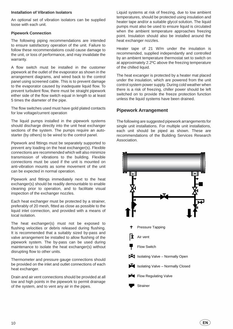
Pipework Arrangement
The following are suggested pipework arrangements for single unit installations. For multiple unit installations, each unit should be piped as shown. These are recommendations of the Building Services Research Association.
Isolating Valve – Normally Closed
Flow Regulating Valve
Strainer
Pressure Tapping
Air vent
Flow Switch
Isolating Valve – Normally Open

11EN
Connection Types and Sizes
Standard pipework connections are of the Victaulic groove type.
For connection sizes relevant to individual models refer to the physical data tables in this manual.
Water Treatment
The unit performance given in the Design Guide is based on a fouling factor of 0.018 m² °C/kW. Dirt, scale, grease and certain types of water treatment will adversely affect the heat exchanger surfaces and therefore unit performance. Foreign matter in the water system(s) can increase the pressure drop, reducing the fl ow rate and causing potential damage.
Aerated, brackish or salt water is not recommended for use in the water systems. JCI recommends that a water treatment specialist be consulted to determine whether the proposed water composition will not affect the heat exchanger materials of carbon steel and copper. The pH value of the water fl owing through the unit must be kept between 7 and 8.5.
Water Quality Requirements
The water used in the unit liquid system must meet the requirements detailed in the table below:
Water quality should be inspected before unit installation and regularly during unit operation. The water quality must meet the limits above. If parameters are not within limits, the heat exchanger may leak or have problems within scale formation.These problems may result in the unit not operating normally, excessive heat exchanger pressure drops and reduced nominal capacities.
Allowable Value Corrosion Fouling
pH (25°C) pH 7.0 to 8.5 ■SO4 ppm <100 ■
HCO3/SO4 ppm >1.0 ■Cl ppm <50 ■
PO4 ppm <2.0 ■NH3 ppm <0.5 ■
Free Cl ppm <0.5 ■Fe+++ ppm <0.5 ■Mn++ ppm <0.05 ■CO² ppm <10 ■H²S ppm <50 ■
Temp °C <65 ■ ■O content ppm <0.1 ■Hardness dH 4.8 to 8.5 ■
Item Unit Potential Problem
Refrigerant Relief Valve Piping
The heat exchanger is protected against internal refrigerant overpressure by refrigerant relief valves. A pressure relief valve is mounted on each of the main refrigerant lines connecting the evaporator to the compressors.
For indoor installations, pressure relief valves should be piped to the exterior of the building.
The size of any pipework attached to a relief valve must be of suffi cient diameter so as not to cause resistance to the operation of the valve. For critical or complex installations refer to EN13136.
Unless otherwise specifi ed by local regulations, the internal diameter depends on the length of pipe required and can be estimated with the following formula:
D5=1.447 x L
Where:D = minimum pipe internal diameter (cm)L = length of pipe (m).
If relief pipework is common to more than one valve its cross sectional area must be at least the total required by each valve. Valve types should not be mixed on a common pipe. Precautions should be taken to ensure that the exit of relief valves/vent pipe remain clear of obstructions at all times.
Electrical Connection
The following connection recommendations are intended to ensure safe and satisfactory operation of the unit. Failure to follow these recommendations could cause harm to persons, or damage to the unit, and may invalidate the warranty.
No additional controls (relays, etc.) should be mounted in the control panel. Power and control wiring not connected to the control panel should not be run through the control panel. If these precautions are not followed it could lead to a risk of electrocution. In addition, electrical noise could cause malfunctions or damage the unit and its controls.
Power Wiring
These units are suitable for 400 V, 3-phase, 50Hz nominal supplies only.
All electrical wiring should be carried out in accordance with local regulations. Route properly sized cables to the cable entries in the bottom of the power panel.
In accordance with EN 60204 it is the responsibility of the user to install over current protection devices between the supply conductors and the power supply terminals on the unit.
To ensure that no eddy currents are set up in the power panel, the cables forming each 3 phase power supply must enter via the same cable entry.
All sources of supply to the unit must be taken via a common point of isolation (not supplied by JCI).
12 EN
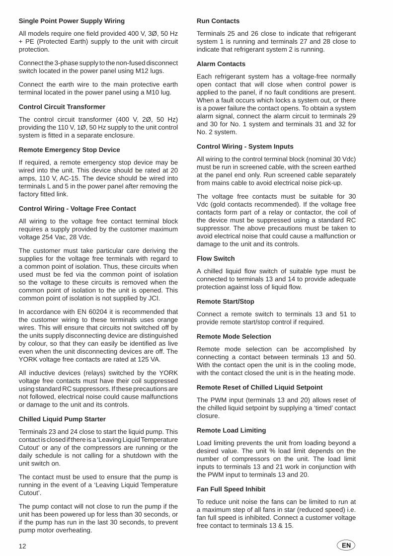
Single Point Power Supply Wiring
All models require one fi eld provided 400 V, 3Ø, 50 Hz + PE (Protected Earth) supply to the unit with circuit protection.
Connect the 3-phase supply to the non-fused disconnect switch located in the power panel using M12 lugs.
Connect the earth wire to the main protective earth terminal located in the power panel using a M10 lug.
Control Circuit Transformer
The control circuit transformer (400 V, 2Ø, 50 Hz) providing the 110 V, 1Ø, 50 Hz supply to the unit control system is fi tted in a separate enclosure.
Remote Emergency Stop Device
If required, a remote emergency stop device may be wired into the unit. This device should be rated at 20 amps, 110 V, AC-15. The device should be wired into terminals L and 5 in the power panel after removing the factory fi tted link.
Control Wiring - Voltage Free Contact
All wiring to the voltage free contact terminal block requires a supply provided by the customer maximum voltage 254 Vac, 28 Vdc.
The customer must take particular care deriving the supplies for the voltage free terminals with regard to a common point of isolation. Thus, these circuits when used must be fed via the common point of isolation so the voltage to these circuits is removed when the common point of isolation to the unit is opened. This common point of isolation is not supplied by JCI.
In accordance with EN 60204 it is recommended that the customer wiring to these terminals uses orange wires. This will ensure that circuits not switched off by the units supply disconnecting device are distinguished by colour, so that they can easily be identifi ed as live even when the unit disconnecting devices are off. The YORK voltage free contacts are rated at 125 VA.
All inductive devices (relays) switched by the YORK voltage free contacts must have their coil suppressed using standard RC suppressors. If these precautions are not followed, electrical noise could cause malfunctions or damage to the unit and its controls.
Chilled Liquid Pump Starter
Terminals 23 and 24 close to start the liquid pump. This contact is closed if there is a ‘Leaving Liquid Temperature Cutout’ or any of the compressors are running or the daily schedule is not calling for a shutdown with the unit switch on.
The contact must be used to ensure that the pump is running in the event of a ‘Leaving Liquid Temperature Cutout’.
The pump contact will not close to run the pump if the unit has been powered up for less than 30 seconds, or if the pump has run in the last 30 seconds, to prevent pump motor overheating.
Run Contacts
Terminals 25 and 26 close to indicate that refrigerant system 1 is running and terminals 27 and 28 close to indicate that refrigerant system 2 is running.
Alarm Contacts
Each refrigerant system has a voltage-free normally open contact that will close when control power is applied to the panel, if no fault conditions are present. When a fault occurs which locks a system out, or there is a power failure the contact opens. To obtain a system alarm signal, connect the alarm circuit to terminals 29 and 30 for No. 1 system and terminals 31 and 32 for No. 2 system.
Control Wiring - System Inputs
All wiring to the control terminal block (nominal 30 Vdc) must be run in screened cable, with the screen earthed at the panel end only. Run screened cable separately from mains cable to avoid electrical noise pick-up.
The voltage free contacts must be suitable for 30 Vdc (gold contacts recommended). If the voltage free contacts form part of a relay or contactor, the coil of the device must be suppressed using a standard RC suppressor. The above precautions must be taken to avoid electrical noise that could cause a malfunction or damage to the unit and its controls.
Flow Switch
A chilled liquid fl ow switch of suitable type must be connected to terminals 13 and 14 to provide adequate protection against loss of liquid fl ow.
Remote Start/Stop
Connect a remote switch to terminals 13 and 51 to provide remote start/stop control if required.
Remote Mode Selection
Remote mode selection can be accomplished by connecting a contact between terminals 13 and 50. With the contact open the unit is in the cooling mode, with the contact closed the unit is in the heating mode.
Remote Reset of Chilled Liquid Setpoint
The PWM input (terminals 13 and 20) allows reset of the chilled liquid setpoint by supplying a ‘timed’ contact closure.
Remote Load Limiting
Load limiting prevents the unit from loading beyond a desired value. The unit % load limit depends on the number of compressors on the unit. The load limit inputs to terminals 13 and 21 work in conjunction with the PWM input to terminals 13 and 20.
Fan Full Speed Inhibit
To reduce unit noise the fans can be limited to run at a maximum step of all fans in star (reduced speed) i.e. fan full speed is inhibited. Connect a customer voltage free contact to terminals 13 & 15.

13EN
EMS Analogue Input
Provides a means of resetting the leaving chilled or hot liquid temperature from the BAS/EMS. Accepts 4 to 20 mA, 0 to 20 mA, 0 to 10 Vdc or 2-10 Vdc. Connect to terminal A+ and A-.
Modbus, BACnet MS/TP and N2
Enable communications with building protocol systems using Modbus, BACnet or N2 protocol. Connect through standard RS485 port.
Connection Diagram
13 13 13 13 13 14 1513 20 21 50 51 A+A-A+-XTBC3-XTBC1
L 5
LK
23 24 25 26 27 28 29 30 31 32 33 34-XTBC2
ELECTRONIC SECTIONPOWER SECTION ELECTRONIC SECTIONPOWER SECTION
M 1
M 2
TUS
TUS
ACT
23 24 25 26 27 28 29 30 31 32 33 34
ON NLY
H Y GTT L
13 14 13 15 13 20 13 21 13 50 13 51 A+ A-
STA
TUS
SYST
EM
STA
TUS
SYST
EM
1 A
LARM
STA
T
2 A
LARM
STA
T
P ST
ART
CO
NTA
OD
E IN
DIC
ATI
OVE
RY O
PTIO
N O
E ST
ART
/ S
TOP
FLO
W S
WIT
C H
D IN
HIB
ITN
OPT
ION
ON
LY
D F
OR
HEA
TIN
G
AG
E LO
AD
LIM
IT
OR
PWM
INPU
T
E RE
SET
SIG
NA
L
REMOTE EMERGENCYSTOP DEVICE
CHIL
LER
RUN
S
CHIL
LER
RUN
S
SYST
EM 1
SYST
EM
LIQ
UID
PU
MP
COO
LIN
G M
HEA
T RE
COV
REM
OTE
FAN
SPE
EDTW
O S
PEED
FA
N
ECTI
ON
CLO
SED
1STST
A
GE
LOA
D L
IMIT
TEM
PERA
TURE
T
MO
DE
SEL
2ND
STA
G
AN
ALO
GU
E
YLPA CUSTOMER WIRING

14 EN
Refrigerant to Water Heat Exchanger Pressure Drop Graph
Operating Limitations
10 15 20 6030 40
10
15
20
30
405060
80100120150180210
Flow Rate (l/s)
Pre
ssur
e D
rop
(kP
a)
50
5
0340SE
0355HE
0570HE0640HE
0415SE 0495SE 0560SE 0610SE 0425HE 0505HE
522
Min. Max. Min. Max. Min. Max. Min. Max. Min. Max.
Liquid Outlet Temperature (Water) °CLiquid Outlet Temperature Range (T) °CAir Temperature - Standard Unit °CLiquid Outlet Temperature (Water) °CLiquid Outlet Temperature Range (T) °CAir Temperature - Standard Unit °C
l/s 6 38 11 44 11 44 11 44 11 44
kPa 7.7 191.3 16.0 128.7 16.0 128.7 16.0 128.7 16.0 128.7
barbarV
Min. Max. Min. Max. Min. Max. Min. Max. Min. Max.
Liquid Outlet Temperature (Water) °CLiquid Outlet Temperature Range (T) °CAir Temperature - Standard Unit °CLiquid Outlet Temperature (Water) °CLiquid Outlet Temperature Range (T) °CAir Temperature - Standard Unit °C
l/s 8 38 11 44 11 44 13 54 13 54
kPa 5.3 88.4 16.0 128.7 16.0 128.7 10.1 165.6 10.1 165.6
barbarV
(1) Unit may operate unloaded up to 52ºC depending on model size and site conditions.(2) Tolerance +/-10%
0505HE
0 to 46 (1)
YLPA High Efficiency 0425HE
Power Supply Voltage
Maximum Water Side PressureMaximum Refrigerant Side Pressure
Power Supply Voltage
Cooling Mode
Heating Mode
Heat Exchanger Presssure DropHeat Exchanger Flow Rate
35 to 55
4 to 15
10.344.8
3 to 8
Heating Mode
Maximum Refrigerant Side Pressure
Heat Exchanger Flow Rate
Maximum Water Side PressureHeat Exchanger Presssure Drop
-10 to 35
400V 3Ø, 50Hz (nominal) (2)
3 to 8
10.344.8
400V 3Ø, 50Hz (nominal) (2)
0570HE
-10 to 35
0355HE 0640HE
3 to 8
0610SE0495SE0415SE0340SE
35 to 55
YLPA Standard Efficiency
4 to 153 to 8
0560SE
Cooling Mode
0 to 46 (1)

15EN
Physical Data0340SE 0415SE 0495SE 0560SE 0610SE
Number of refrigerant circuitsRefrigerant Charge (1) Circuit 1 / Circuit 2 kg 40/42 68/50 68/68 80/76 81/81Oil Charge Circuit 1 / Circuit 2 l 11/11 17/11 17/17 18.9/17 18.9/18.9
Number of compressors 2 / 2 3 / 2 3 / 3 3 / 3 3 / 3TypeNumberTypeWater Volume l 200Water Connections InchNumber of Fans (circuit 1 / circuit 2) 3 / 3 4 / 3 4 / 4 5/5 6 / 6Total Air Flow - Standard Models m3/s 35 41 47 58 70Length mm 4937 4937 4937 5854 6971Width mm 2246 2246 2246 2246 2246Height mm 2501 2501 2501 2501 2501Shipping Weight kg 4400 4700 4900 5395 5935Operating Weight kg 4600 5000 5200 5695 6235
0355HE 0425HE 0505HE 0570HE 0640HENumber of refrigerant circuitsRefrigerant Charge (1) Circuit 1 / Circuit 2 kg 59/62 82/60 82/82 104/95 104/110Oil Charge Circuit 1 / Circuit 2 l 11/11 17/11 17/17 18.9/17 18.9/18.9
Number of compressors 2 / 2 3 / 2 3 / 3 3 / 3 3 / 3TypeNumberTypeWater Volume l 250Water Connections Inch 10 10Number of Fans (circuit 1 / circuit 2) 4 / 4 6 / 4 6 / 6 6 / 6 6 / 6Total Air Flow - Standard Models m3/s 47 58 70 70 70Length mm 4937 5854 6971 6971 6971Width mm 2246 2246 2246 2246 2246Height mm 2501 2501 2501 2501 2501Shipping Weight kg 4500 5100 5800 6095 6295Operating Weight kg 4750 5400 6100 6495 6695
(1) Liquid sub-cooling measured at the liquid line should be between 8.5 and 11.0°C at circuit full load. Sub-cooling is determined by the level of refrigerant charge in each system
YLPA
Compressor
Refrigerant to Water Heat Exchanger 300
8
2
Scroll1
Shell and Tubes
Basic Unit Weight
Refrigerant to Water Heat Exchanger 600300
Ambient Coils Fans
1Shell and Tubes
8
Ambient Coils Fans
Dimensions
Dimensions
Basic Unit Weight
2YLPA
CompressorScroll

16 EN
Fan Data
Compressor Data
Electrical Data
KW FLC @400V [email protected] 4.33 18
Slow 1.15 2.45 6Fast 1.64 4.33 18
1.4 2.2 2.2Values are for each fan. (FLA: Full Load Amps; LRA: Lock Rotor Amps)VSD Option
Fan DataFAN TYPE
StandardTwo Speed
Option
KWAmps
@400VKW
Amps@400V
Amps@360V
DOL Soft Start
Standard 43.1 52.9 55.2PF Option 40.8 50.8 53.8Standard 54.9 66.7 70.6PF Option 51.5 63.5 67.3
Compressor DataInrush Current @ 400V
25
32.3
31.7
40.3
310 195
389 233
0340SE to 0505HE Sys 1 & 20560SE and 0570HE Sys 20560SE and 0570HE Sys 10610SE and 0640HE Sys 1 & 2
Nominal MaximumYLPA
Nominal Running Conditions
Amps @ 400 V
Amps @400V
Amps @ 360V
Direct on Line (1)
Soft Start (1)
Soft Start(2)
Standard 198 238 247 465 350 422PF 189 229 241 458 - -PF & SS 194 233 244 - 346 420Standard 207 246 255 474 359 431PF 198 238 250 467 - -PF & SS 202 242 253 - 354 429Standard 246 295 306 513 398 470PF 234 284 299 504 - -PF & SS 239 289 302 - 391 465Standard 259 308 319 526 411 483PF 247 297 312 517 - -PF & SS 252 302 315 - 404 478Standard 293 352 366 560 445 517PF 279 339 357 549 - -PF & SS 284 344 360 - 436 510Standard 311 369 383 577 462 534PF 297 357 375 566 - -PF & SS 301 361 378 - 453 527Standard 337 402 421 671 515 617PF 320 386 406 658 - -PF & SS 326 392 411 - 504 609Standard 346 411 429 680 524 625PF 329 395 415 666 - -PF & SS 335 400 420 - 513 617Standard 381 452 476 715 559 661PF 361 433 455 698 - -PF & SS 368 439 462 - 546 650Standard 381 452 476 715 559 661PF 361 433 455 698 - -PF & SS 368 439 462 - 546 650
PF = Power Factor OptionPF & SS = Power Factor and Soft Start Option(1) Start up amps is the last compressor starting with all other compressors/fans operating at nominal conditions at 400V.(2) Value of Start up amps is the hightest possible with running compressors and all fans operationg at nominal conditions at 400V
0610SE
0640HE
0495SE
0505HE
0560SE
0570HE
0340SE
0355HE
0415SE
0425HE
Unit Data (Using Standard Fans or Two speed Optional Fans at Full Speed)Start up AmpsMaximum Running Conditions
YLPA

17EN
Dimensions - YLPA0355HE
23
7
45
11
6
988k
g82
7kg
984k
g
846k
g46
6kg
642k
g
1D
ista
nce
betw
een
anti
vibr
atio
n m
ount
s
2P
ower
cab
le e
ntry
via
gla
nd p
late
3C
ontr
ol c
able
ent
ry
4W
ater
inle
t con
nect
ion
to h
eat e
xcha
nger
5W
ater
out
let c
onne
ctio
n to
hea
t exc
hang
er
6M
ount
ing
hole
s fo
r an
ti vi
brat
ion
mou
nts
7R
iggi
ng h
oles

18 EN
Dimensions - YLPA0425HE
4
6
11
1
724k
g99
4kg
699k
g77
4kg
463k
g66
7kg
465k
g61
5kg
75
23
1D
ista
nce
betw
een
anti
vibr
atio
n m
ount
s
2P
ower
cab
le e
ntry
via
gla
nd p
late
3C
ontr
ol c
able
ent
ry
4W
ater
inle
t con
nect
ion
to h
eat e
xcha
nger
5W
ater
out
let c
onne
ctio
n to
hea
t exc
hang
er
6M
ount
ing
hole
s fo
r an
ti vi
brat
ion
mou
nts
7R
iggi
ng h
oles

19EN
Dimensions - YLPA0505HE
6
11
1
724k
g10
24kg
1125
kg71
8kg
485k
g70
1kg
745k
g58
0kg
47
5
23
1D
ista
nce
betw
een
anti
vibr
atio
n m
ount
s
2P
ower
cab
le e
ntry
via
gla
nd p
late
3C
ontr
ol c
able
ent
ry
4W
ater
inle
t con
nect
ion
to h
eat e
xcha
nger
5W
ater
out
let c
onne
ctio
n to
hea
t exc
hang
er
6M
ount
ing
hole
s fo
r an
ti vi
brat
ion
mou
nts
7R
iggi
ng h
oles

20 EN
Dimensions - YLPA0570HE
11
1
6
5
47
23
1D
ista
nce
betw
een
anti
vibr
atio
n m
ount
s
2P
ower
cab
le e
ntry
via
gla
nd p
late
3C
ontr
ol c
able
ent
ry
4W
ater
inle
t con
nect
ion
to h
eat e
xcha
nger
5W
ater
out
let c
onne
ctio
n to
hea
t exc
hang
er
6M
ount
ing
hole
s fo
r an
ti vi
brat
ion
mou
nts
7R
iggi
ng h
oles
21EN
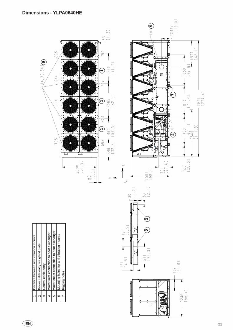
Dimensions - YLPA0640HE
11
1
6
5
47
23
1D
ista
nce
betw
een
anti
vibr
atio
n m
ount
s
2P
ower
cab
le e
ntry
via
gla
nd p
late
3C
ontr
ol c
able
ent
ry
4W
ater
inle
t con
nect
ion
to h
eat e
xcha
nger
5W
ater
out
let c
onne
ctio
n to
hea
t exc
hang
er
6M
ount
ing
hole
s fo
r an
ti vi
brat
ion
mou
nts
7R
iggi
ng h
oles

22 EN
Dimensions - YLPA0340SE
4937
23
45
11
6 7
957k
g80
1kg
952k
g
819k
g45
1kg
621k
g
1D
ista
nce
betw
een
anti
vibr
atio
n m
ount
s
2P
ower
cab
le e
ntry
via
gla
nd p
late
3C
ontr
ol c
able
ent
ry
4W
ater
inle
t con
nect
ion
to h
eat e
xcha
nger
5W
ater
out
let c
onne
ctio
n to
hea
t exc
hang
er
6M
ount
ing
hole
s fo
r an
ti vi
brat
ion
mou
nts
7R
iggi
ng h
oles

23EN
Dimensions - YLPA0415SE
4
116
886k
g10
84kg
1066
kg
620k
g66
8kg
706k
g
57
23
1D
ista
nce
betw
een
anti
vibr
atio
n m
ount
s
2P
ower
cab
le e
ntry
via
gla
nd p
late
3C
ontr
ol c
able
ent
ry
4W
ater
inle
t con
nect
ion
to h
eat e
xcha
nger
5W
ater
out
let c
onne
ctio
n to
hea
t exc
hang
er
6M
ount
ing
hole
s fo
r an
ti vi
brat
ion
mou
nts
7R
iggi
ng h
oles

24 EN
Dimensions - YLPA0495SE
6
11
1009
kg10
06kg
1117
kg
742k
g61
3kg
734k
g
45
7
2
3
1D
ista
nce
betw
een
anti
vibr
atio
n m
ount
s
2P
ower
cab
le e
ntry
via
gla
nd p
late
3C
ontr
ol c
able
ent
ry
4W
ater
inle
t con
nect
ion
to h
eat e
xcha
nger
5W
ater
out
let c
onne
ctio
n to
hea
t exc
hang
er
6M
ount
ing
hole
s fo
r an
ti vi
brat
ion
mou
nts
7R
iggi
ng h
oles

25EN
Dimensions - YLPA0560SE
6
11
1
4
5
7
23
1D
ista
nce
betw
een
anti
vibr
atio
n m
ount
s
2P
ower
cab
le e
ntry
via
gla
nd p
late
3C
ontr
ol c
able
ent
ry
4W
ater
inle
t con
nect
ion
to h
eat e
xcha
nger
5W
ater
out
let c
onne
ctio
n to
hea
t exc
hang
er
6M
ount
ing
hole
s fo
r an
ti vi
brat
ion
mou
nts
7R
iggi
ng h
oles

26 EN
Dimensions - YLPA0610SE
11
16
5
47
23
1D
ista
nce
betw
een
anti
vibr
atio
n m
ount
s
2P
ower
cab
le e
ntry
via
gla
nd p
late
3C
ontr
ol c
able
ent
ry
4W
ater
inle
t con
nect
ion
to h
eat e
xcha
nger
5W
ater
out
let c
onne
ctio
n to
hea
t exc
hang
er
6M
ount
ing
hole
s fo
r an
ti vi
brat
ion
mou
nts
7R
iggi
ng h
oles

27EN

Form 150.68-EG1.EN.CE (0911) Subject to change without notice. ALL RIGHTS RESERVED
www.johnsoncontrols.com