foreword - stars club franceatelierstarsclub.free.fr/pdf/5bn4-ae1.pdf · foreword this...
TRANSCRIPT


FOREWORD
This Supplementary Service Manual has been prepared to introduce new service and data for theXVS650 ’97. For complete service information procedures it is necessary to use this SupplementaryService Manual together with the followin manual.
XVS650 ’97 SERVICE MANUAL: 4VR-AE1
XVS650A ’98SUPPLEMENTARYSERVICE MANUAL
1998 by Yamaha Motor Co., Ltd.First Edition, Feburary 1998
All rights reserved. Any reproduction orunauthorized use without the writtenpermission fo Yamaha Motor Co., Ltd.
is expressly prohibited.

NOTE:
CAUTION:
EB001000
NOTICEThis manual was produced by the Yamaha Motor Company primarily for use by Yamaha dealers andtheir qualified mechanics. It is not possible to include all the knowledge of a mechanic in one manual,so it is assumed that anyone who uses this book to perform maintenance and repairs on Yamaha mo-torcycles has a basic understanding of the mehanical ideas and the procedures of motorcycle repair.Repairs attempted by anyone without this knowledge are likely to render the motorcycle unsafe andunfit for use.
Yamaha Motor Company, Ltd. is ontinually striving to improve all its models. Modifications and signifi-cant changes in specifications or procedures will be forwarded to all authorized Yamaha dealers andwill appear in future editions of this manual where applicable.
Designs and specifications are subject to change without notice.
IMPORTANT INFORMATIONParticularly important information is distinguished in this manual by the following notations.
The Safety Alert Symbol means ATTENTION! BECOME ALERT! YOURSAFETY IS INVOLVED!
Failure to follow WARNING instructions could result in severe injury or death tothe motorcycle operator, a bystander or a person inspecting or repairing themotorcycle.
A CAUTION indicates special precautions that must be taken to avoid damageto the motorcycle.
NOTE: A NOTE provides key information to make procedures easier or clearer.
12 6
3
5
4
7
8
EB002000
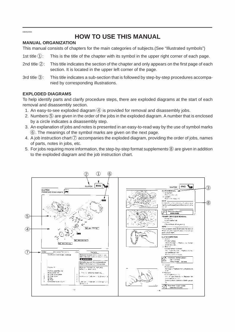
HOW TO USE THIS MANUALMANUAL ORGANIZATIONThis manual consists of chapters for the main categories of subjects.(See “Illustrated symbols”)
1st title 1 : This is the title of the chapter with its symbol in the upper right corner of each page.
2nd title 2 : This title indicates the section of the chapter and only appears on the first page of eachsection. It is located in the upper left corner of the page.
3rd title 3 : This title indicates a sub-section that is followed by step-by-step procedures accompa-nied by corresponding illustrations.
EXPLODED DIAGRAMSTo help identify parts and clarify procedure steps, there are exploded diagrams at the start of eachremoval and disassembly section.
1. An easy-to-see exploded diagram 4 is provided for removal and disassembly jobs.2. Numbers 5 are given in the order of the jobs in the exploded diagram. A number that is enclosed
by a circle indicates a disassembly step.3. An explanation of jobs and notes is presented in an easy-to-read way by the use of symbol marks
6 . The meanings of the symbol marks are given on the next page.4. A job instruction chart 7 accompanies the exploded diagram, providing the order of jobs, names
of parts, notes in jobs, etc.5. For jobs requiring more information, the step-by-step format supplements 8 are given in addition
to the exploded diagram and the job instruction chart.

1
3
5
7
9
11
13
15
18
2
4
8
10
12
14
16
6
21
24 25
17
19 20
22 23
EB003000
ILLUSTRATED SYMBOLSIllustrated symbols 1 to 9 are printed on thetop right of each page and indicate the subjectof each chapter.
1 General information2 Specifications3 Periodic inspections and adjustments4 Engine5 Cooling system6 Carburetion7 Chassis8 Electrical9 Troubleshooting
Illustrated symbols 10 to 17 are use to identifythe specifications appearing in the text.
10 Can be serviced with engine mounted11 Filling fluid12 Lubricant13 Special tool14 Torque15 Wear limit, clearance16 Engine speed17 Ω, V, A
Illustrated symbols 18 to 23 in the exploded dia-grams indicate the types of lubricants and lu-brication points.
18 Apply engine oil19 Apply gear oil20 Apply molybdenum disulfide oil21 Apply wheel bearing grease22 Apply lightweight lithium-soap base grease23 Apply molybdenum disulfide grease
Illustrated symbols 24 to 25 in the exploded dia-grams indicate where to apply a locking agent 24and when to install new parts 25.
24 Apply locking agent (LOCTITE )25 Replace

CONTENTS
GENERAL INFORMATION 1. . . . . . . . . . . . . . . . . . . . . . . . . . . . . . . . . . . . . . MOTORCYCLE IDENTIFICATION 1. . . . . . . . . . . . . . . . . . . . . . . . . . . .
VEHICLE IDENTIFICATION NUMBER 1. . . . . . . . . . . . . . . . . . . . . MODEL LABEL 1. . . . . . . . . . . . . . . . . . . . . . . . . . . . . . . . . . . . . . . . . .
SPECIFICATIONS 2. . . . . . . . . . . . . . . . . . . . . . . . . . . . . . . . . . . . . . . . . . . . . GENERAL SPECIFICATIONS 2. . . . . . . . . . . . . . . . . . . . . . . . . . . . . . . . MAINTENANCE SPECIFICATIONS 3. . . . . . . . . . . . . . . . . . . . . . . . . . .
ENGINE 3. . . . . . . . . . . . . . . . . . . . . . . . . . . . . . . . . . . . . . . . . . . . . . . . CHASSIS 3. . . . . . . . . . . . . . . . . . . . . . . . . . . . . . . . . . . . . . . . . . . . . . . ELECTRICAL 4. . . . . . . . . . . . . . . . . . . . . . . . . . . . . . . . . . . . . . . . . . .
CABLE ROUTING 5. . . . . . . . . . . . . . . . . . . . . . . . . . . . . . . . . . . . . . . . . .
PERIODIC INSPECTION AND ADJUSTMENT 16. . . . . . . . . . . . . . . . . . . . FUEL TANK AND SEATS 16. . . . . . . . . . . . . . . . . . . . . . . . . . . . . . . . . . . . HEAD LICHT BEAM ADJUSTMENT 17. . . . . . . . . . . . . . . . . . . . . . . . . . . HEAD LICHT BULB REPLACEMENT 17. . . . . . . . . . . . . . . . . . . . . . . . . .
ENGINE 18. . . . . . . . . . . . . . . . . . . . . . . . . . . . . . . . . . . . . . . . . . . . . . . . . . . . . . ENGINE REMOVAL 18. . . . . . . . . . . . . . . . . . . . . . . . . . . . . . . . . . . . . . . . .
CYLINDER HEAD COVERS REMOVAL 18. . . . . . . . . . . . . . . . . . . .
CARBURATION 20. . . . . . . . . . . . . . . . . . . . . . . . . . . . . . . . . . . . . . . . . . . . . . . AIR INDUCTION SYSTEM(AIS) <For D,A> 20. . . . . . . . . . . . . . . . . . . . .
AIR INDUCTION 20. . . . . . . . . . . . . . . . . . . . . . . . . . . . . . . . . . . . . . . . . AIR CUT-OFF VALVES 20. . . . . . . . . . . . . . . . . . . . . . . . . . . . . . . . . . . AIR INDUCTION SYSTEM INSPECTION 21. . . . . . . . . . . . . . . . . . .
CHASSIS 22. . . . . . . . . . . . . . . . . . . . . . . . . . . . . . . . . . . . . . . . . . . . . . . . . . . . . FRONT FORK 22. . . . . . . . . . . . . . . . . . . . . . . . . . . . . . . . . . . . . . . . . . . . . .
FRONT FORK DISASSEMBLY 26. . . . . . . . . . . . . . . . . . . . . . . . . . . . FRONT FORK INSPECTION 27. . . . . . . . . . . . . . . . . . . . . . . . . . . . . . FRONT FORK ASSEMBLY 27. . . . . . . . . . . . . . . . . . . . . . . . . . . . . . . FRONT FORD INSTALLATION 30. . . . . . . . . . . . . . . . . . . . . . . . . . . .
STEERING HEAD 32. . . . . . . . . . . . . . . . . . . . . . . . . . . . . . . . . . . . . . . . . .


– 1 –
MOTORCYCLE IDENTIFICATIONGENINFO
EB100000
GENERAL INFORMATIONMOTORCYCLE IDENTIFICATIONEB100010
VEHICLE IDENTIFICATION NUMBERThe vehicle identification number 1 isstamped into the right side of the steeringhead.
MODEL LABELThe model label 1 is affixed to the frame. Thisinformation will be needed to order spare parts.
– 2 –
GENERAL SPECIFICATIONS SPEC
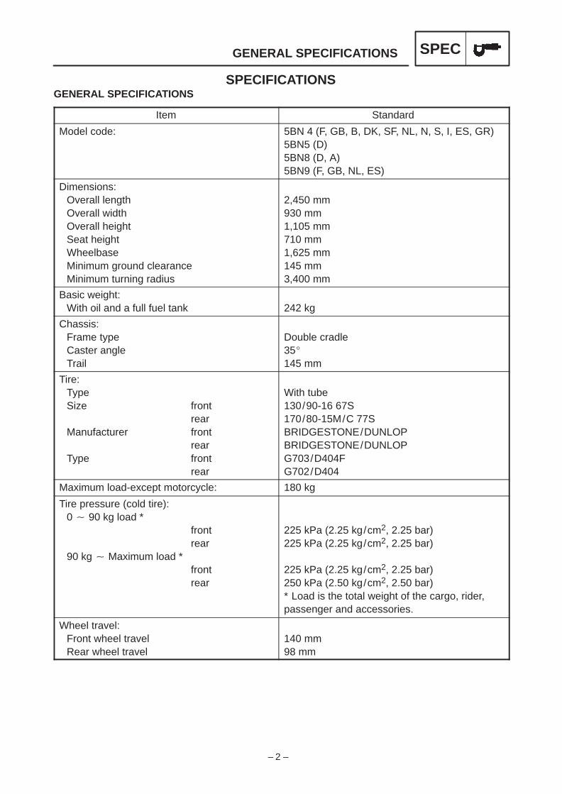
SPECIFICATIONSGENERAL SPECIFICATION S
Item Standard
Model code: 5BN 4 (F, GB, B, DK, SF, NL, N, S, I, ES, GR)5BN5 (D)5BN8 (D, A)5BN9 (F, GB, NL, ES)
Dimensions:Overall lengthOverall widthOverall heightSeat heightWheelbaseMinimum ground clearanceMinimum turning radius
2,450 mm930 mm1,105 mm710 mm1,625 mm145 mm3,400 mm
Basic weight:With oil and a full fuel tank 242 kg
Chassis:Frame typeCaster angleTrail
Double cradle35145 mm
Tire:TypeSize front
rearManufacturer front
rearType front
rear
With tube130/90-16 67S170/80-15M/C 77SBRIDGESTONE/DUNLOPBRIDGESTONE/DUNLOPG703/D404FG702/D404
Maximum load-except motorcycle: 180 kg
Tire pressure (cold tire):0 90 kg load *
frontrear
90 kg Maximum load *frontrear
225 kPa (2.25 kg/cm2, 2.25 bar)225 kPa (2.25 kg/cm2, 2.25 bar)
225 kPa (2.25 kg/cm2, 2.25 bar)250 kPa (2.50 kg/cm2, 2.50 bar)* Load is the total weight of the cargo, rider,passenger and accessories.
Wheel travel:Front wheel travelRear wheel travel
140 mm98 mm

– 3 –
MAINTENANCE SPECIFICATIONS SPEC
MAINTENANCE SPECIFICATIONSENGINE
Item Standard Limit
Carburetor:I. D. mark
Main jet (M.J)Main air jet (M.A.J)Jet needle (J.N)
Needle jet (N.J)Pilot air jet (P.A.J.1)Pilot outlet (P.O)Pilot jet (P.J)Bypass 1 (B.P.1)Bypass 2 (B.P.2)Bypass 3 (B.P.3)Pilot screw (P.S)Valve seat size (V.S)Starter jet (G.S.1)Starter jet (G.S.2)Throttle valve size (Th.V)Fuel level (F.L)Engine idle speedIntake vacuumCO %Engine oil temperature
4VR 00(5BN4), 4XR-00 (5BN9),5BN5-20 (5BN5), 5BN8-30 (5BN8)#90#504CP10-3 (5BN4), 4CZ11-3 (5BN9),4CT2-2 (5BN5/8)O-6 (5BN4/9) O-4 (5BN5/8)#1000.85#200.80.80.82 (5BN4/9), 2-1/2 (5BN5/8)1.0#17.50.9#1407.5 8.5 mm1,150 1,250 r/min29.0 kPa (0.29 kg/cm2, 220 mmHg)3 4 %80 90 C
CHASSIS
Item Standard Limit
Front suspension:Front fork travelFork spring free lengthFitting lengthSpring rate (K1)Stroke (K1)Optional springOil capacityOil levelOil grade
140 mm332.5 mm287.4 mm3.5 N/mm (0.35 kg/mm)0 140 mmNo0.507 L95 mmFork oil 10W or equivalent
325.9 mm
Rear suspension:Shock absorber travelSpring free lengthFitting lengthSpring rate (K1)Stroke (K1)Optional spring
42 mm179.5 mm165.5 mm137 N/mm (13.7 kg/mm)0 42 mmNo
165 mm

– 4 –
MAINTENANCE SPECIFICATIONS SPEC
Item Standard Limit
Front wheel:TypeRim sizeRim materialRim runout limit radial
lateral
Spoke wheel16 MT3.00Steel1.0 mm0.5 mm
2 mm2 mm
Front brake:TypeDisc outside diameter thicknessPad thickness innerPad thickness outer
Single disk298 5 mm6.0 mm6.0 mm
0.8 mm0.8 mm
Master cylinder inside diameterCaliper cylinder inside diameterCaliper cylinder inside diameterBrake fluid type
14.0 mm30.2 mm33.3 mmDOT 4
ELECTRICAL
Item Standard Limit
Rectifier regulator:TypeModel/manufacturerNo load regulated voltageCapacityWithstand voltage
Semi-conductor, short-circuit typeSH650D-11/SHINDENGEN14.1 14.9 V18 A200 V
Horn:TypeQuantityModel/manufacturerMaximum amperage
Plane type1YF-12/NIKKO3.0 A

– 5 –
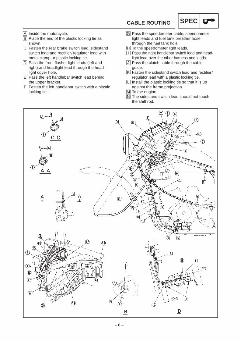
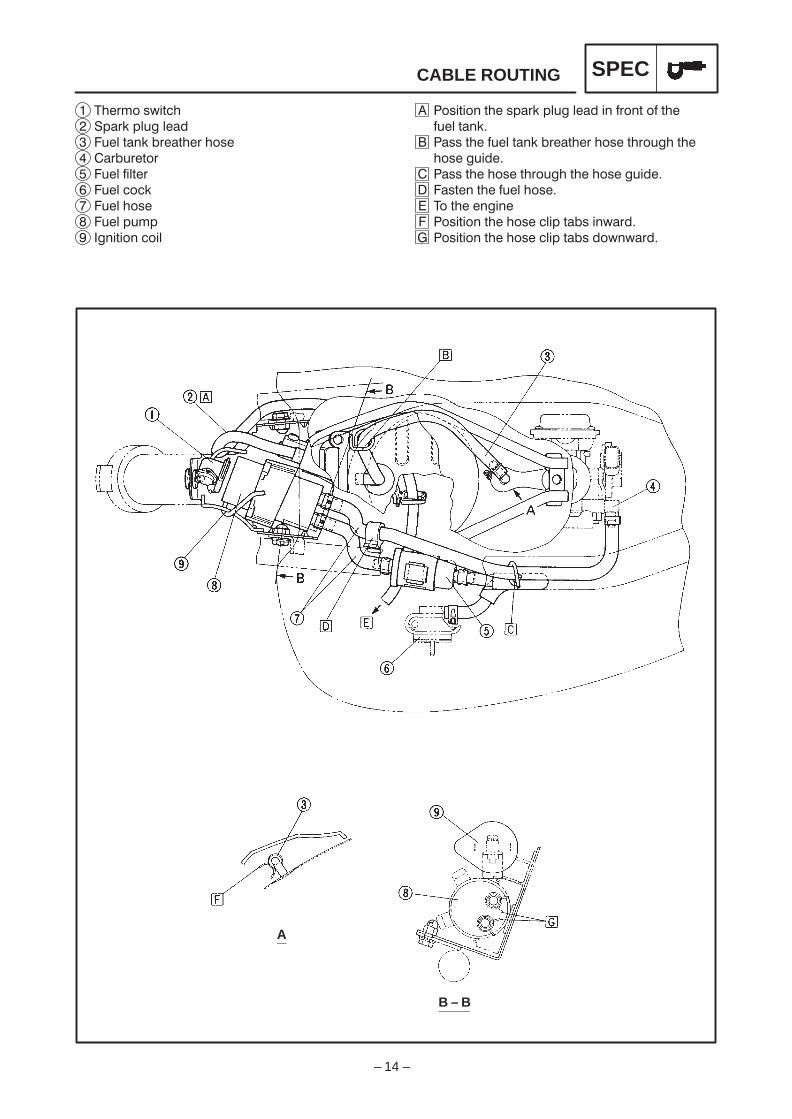
19 Spark plug lead20 Fuel pump
10 Sidestand switch lead11 Rear brake switch lead12 Horn13 Headlinght lead14 Right handlebar switch lead15 Main switch16 Main switch lead17 Fuel pump lead18 Fuel hose
1 Frame2 Clutch cable3 Left handlebar switch lead4 Fuel tank breather hose5 Speedometer cable6 Speedometer7 Speedometer light leads8 Vacuum chamber air vent hose9 Rectifier / regulator
CABLE ROUTING SPEC
EB206000
CABLE ROUTING
– 6 –
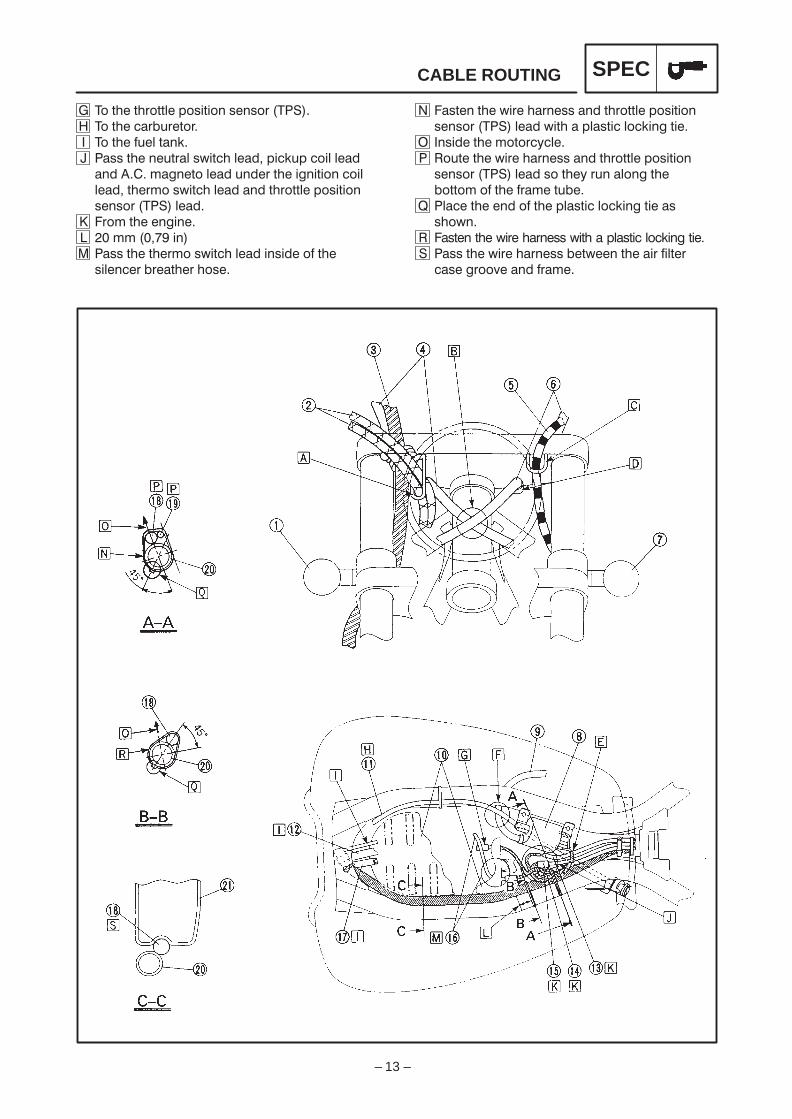
G Pass the speedometer cable, speedometerlight leads and fuel tank breather hosethrough the fuel tank hole.
H To the speedometer light leads.I Pass the right handlebar switch lead and head-
light lead over the other harness and leads.J Pass the clutch cable through the cable
guide.K Fasten the sidestand switch lead and rectifier/
regulator lead with a plastic locking tie.L Install the plastic locking tie so that it is up
against the frame projection.M To the engine.N The sidestand switch lead should not touch
the shift rod.
A Inside the motorcycle.B Place the end of the plastic locking tie as
shown.C Fasten the rear brake switch lead, sidestand
switch lead and rectifier / regulator lead withmetal clamp or plastic locking tie.
D Pass the front flasher light leads (left andright) and headlight lead through the head-light cover hole.
E Pass the left handlebar switch lead behindthe upper bracket.
F Fasten the left handlebar switch with a plasticlocking tie.
CABLE ROUTING SPEC

– 7 –
U Fasten the rear brake switch lead with a plasticlocking tie.
V To the speedometer light leads.W Pass the fuel tank breather hose and vacuum
chamber air vent hose through the holder.X Pass the speedometer cable through the
holder.Y Place the couplers behind the steering head.
CABLE ROUTING SPEC
O Fasten the sidestand switch lead with a metalclamp.
P Connect the rear brake switch coupler in frontof the roll over valve stay.
Q Install the plastic locking tie immediatelybellow the cable guide bracket.
R Pass the speedometer cable through thespeedometer cable holder.
S To the rectifier / regulator.T Pass the rear brake switch lead between the
frame and rectifier / regulator. Do not pinchthe rear brake switch lead.
– 8 –
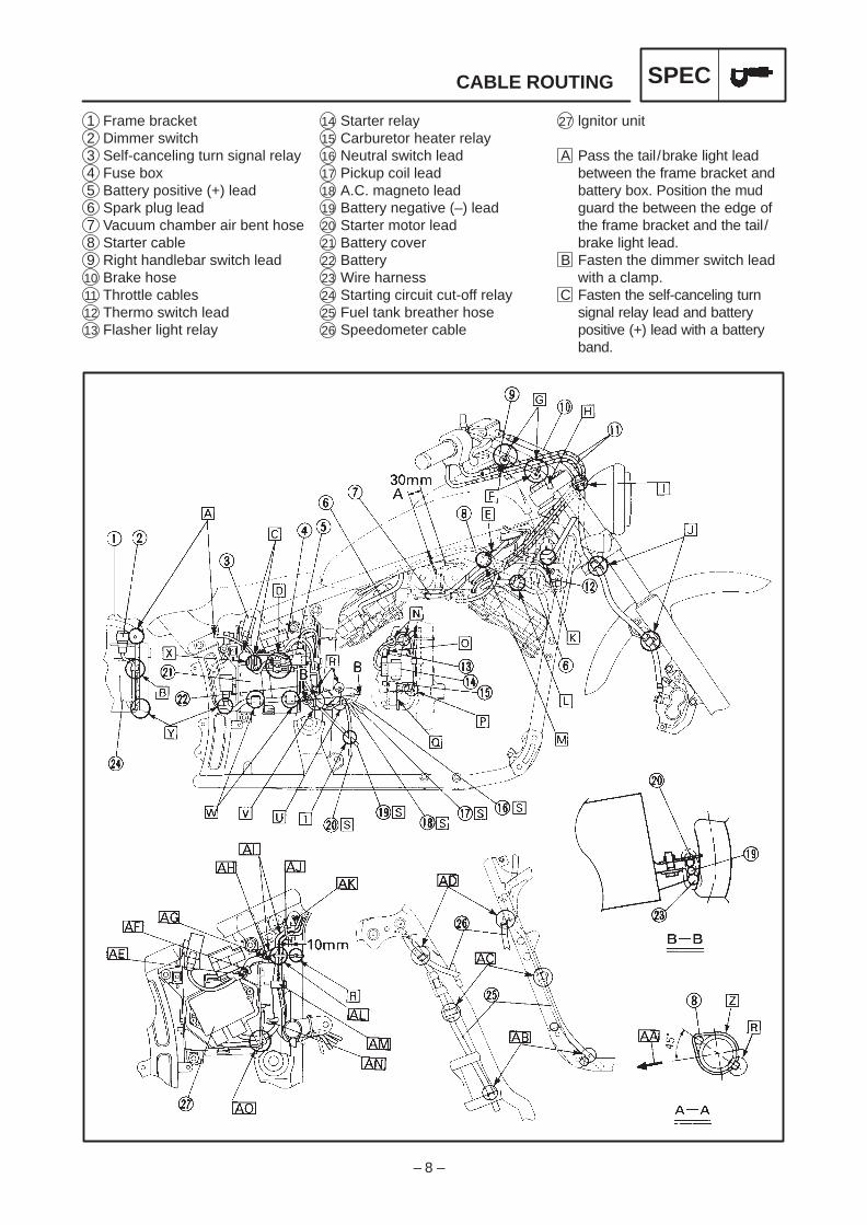
27 lgnitor unit
A Pass the tail/brake light leadbetween the frame bracket andbattery box. Position the mudguard the between the edge ofthe frame bracket and the tail/brake light lead.
B Fasten the dimmer switch leadwith a clamp.
C Fasten the self-canceling turnsignal relay lead and batterypositive (+) lead with a batteryband.
14 Starter relay15 Carburetor heater relay16 Neutral switch lead17 Pickup coil lead18 A.C. magneto lead19 Battery negative (–) lead20 Starter motor lead21 Battery cover22 Battery23 Wire harness24 Starting circuit cut-off relay25 Fuel tank breather hose26 Speedometer cable
1 Frame bracket2 Dimmer switch3 Self-canceling turn signal relay4 Fuse box5 Battery positive (+) lead6 Spark plug lead7 Vacuum chamber air bent hose8 Starter cable9 Right handlebar switch lead10 Brake hose11 Throttle cables12 Thermo switch lead13 Flasher light relay
CABLE ROUTING SPEC

– 9 –
J Fasten the brake hose with a brake hoseholder.
K Pass the left handlebar switch lead under themain switch.
L Fasten the spark plug lead with a metal clamp.M Pass the ignition coil lead inside of the starter
cable.N Fasten the fuse box lead with a plastic locking
tie.
D Fasten the tail/brake light lead coupler and bat-tery negative (–) lead coupler with a clamp.
E To the ignition coil.F The end of the plastic locking tie should face
towards the under the handlebar.G Fasten the right handlebar switch lead with a
plastic locking tie.H Pass the right handlebar switch lead behind
the upper bracket.I Fasten the brake hose grommet with a brake
hose holder. (depending on model type)
CABLE ROUTING SPEC
– 10 –
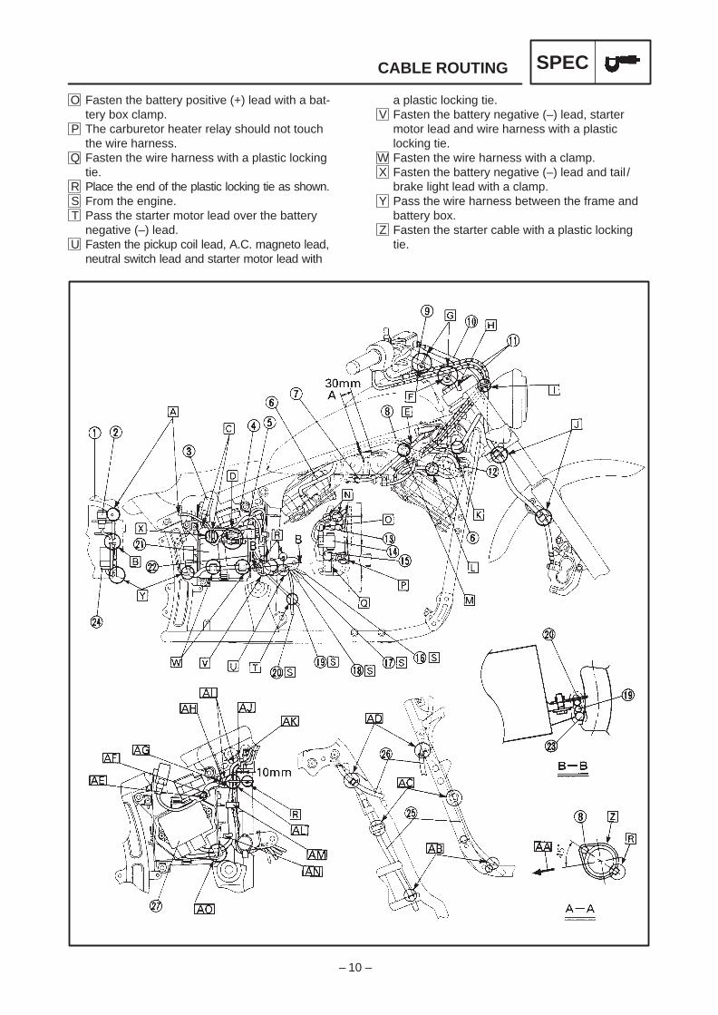
a plastic locking tie.V Fasten the battery negative (–) lead, starter
motor lead and wire harness with a plasticlocking tie.
W Fasten the wire harness with a clamp.X Fasten the battery negative (–) lead and tail /
brake light lead with a clamp.Y Pass the wire harness between the frame and
battery box.Z Fasten the starter cable with a plastic locking
tie.
O Fasten the battery positive (+) lead with a bat-tery box clamp.
P The carburetor heater relay should not touchthe wire harness.
Q Fasten the wire harness with a plastic lockingtie.
R Place the end of the plastic locking tie as shown.S From the engine.T Pass the starter motor lead over the battery
negative (–) lead.U Fasten the pickup coil lead, A.C. magneto lead,
neutral switch lead and starter motor lead with
CABLE ROUTING SPEC
– 11 –
CABLE ROUTING SPEC
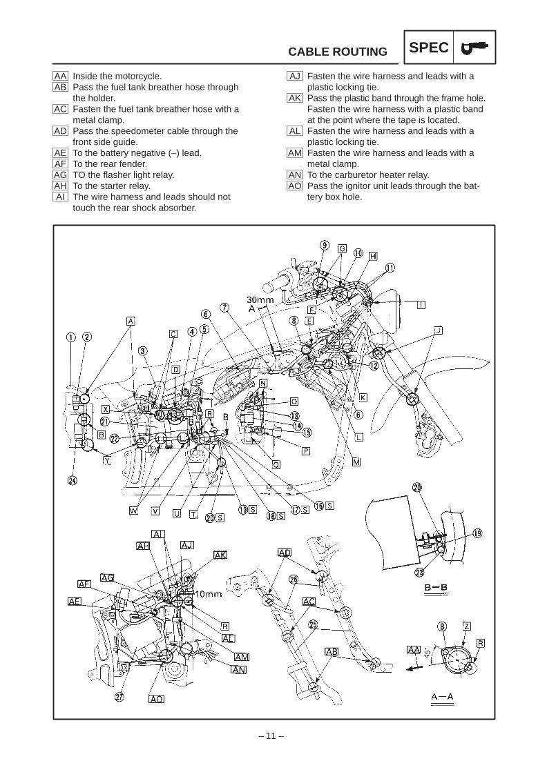
AJ Fasten the wire harness and leads with aplastic locking tie.
AK Pass the plastic band through the frame hole.Fasten the wire harness with a plastic bandat the point where the tape is located.
AL Fasten the wire harness and leads with aplastic locking tie.
AM Fasten the wire harness and leads with ametal clamp.
AN To the carburetor heater relay.AO Pass the ignitor unit leads through the bat-
tery box hole.
AA Inside the motorcycle.AB Pass the fuel tank breather hose through
the holder.AC Fasten the fuel tank breather hose with a
metal clamp.AD Pass the speedometer cable through the
front side guide.AE To the battery negative (–) lead.AF To the rear fender.AG TO the flasher light relay.AH To the starter relay.AI The wire harness and leads should not
touch the rear shock absorber.

– 12 –
12 Speedometer cable13 Neutral switch lead14 Pickup coil lead15 A.C. magneto lead16 Thermo switch lead17 Fuel tank breather hose18 Wire harness19 Throttle position sensor (TPS)
lead20 Frame21 Air filter case
1 Front flasher light (right)2 Throttle cables3 Brake hose4 Right handlebar switch lead5 Clutch cable6 Left handlebar switch lead7 Front flasher light (left)8 Ignition coil9 Spark plug lead10 Silencer11 Starter cable
CABLE ROUTING SPEC
– 13 –
+,' ," /#* "*'++ ' ,"*(,,% )(+#,#('
+'+(* % /#," )%+,# %($#'! ,#
'+# ," &(,(*0%
(-, ," /#* "*'++ ' ,"*(,,% )(+#,#('
+'+(* % +( ,"0 *-' %('! ,"
(,,(& ( ," *& ,-
% ," ' ( ," )%+,# %($#'! ,# +
+"(/'
+,' ," /#* "*'++ /#," )%+,# %($#'! ,#
++ ," /#* "*'++ ,/' ," #* #%,*
+ !*((. ' *&
( ," ,"*(,,% )(+#,#(' +'+(*
( ," *-*,(*
( ," -% ,'$
++ ," '-,*% +/#," % )#$-) (#% %
' &!',( % -'* ," #!'#,#(' (#%
% ,"*&( +/#," % ' ,"*(,,% )(+#,#('
+'+(* %
*(& ," '!#'
&& #'
++ ," ,"*&( +/#," % #'+# ( ,"
+#%'* *,"* "(+
CABLE ROUTING SPEC
– 14 –
A
B – B
$'($# ( '%& %!) ! # &$#( $ (
)! (#
'' ( )! (# &(& $' (&$) (
$' )
'' ( $' (&$) ( $' )
'(# ( )! $'
$ ( ##
$'($# ( $' !% (' #*&
$'($# ( $' !% (' $*#*&
CABLE ROUTING SPEC
&"$ '*(
%& %!) !
)! (# &(& $'
&)&($&
)! !(&
)! $
)! $'
)! %)"%
#($# $!

– 15 –
A
CABLE ROUTING SPEC
*" )$! ')' %(
'*')%'
*" %(
*" ")'
&'! &"* "
*" &*#& "
*" &*#&
%""%+' +"+
$ ) %$ % "
% ) '%""%+' +"+
% ) $ $
'%# ) *" %!
%( ) %$ ) %( " & )( %,$,'
'%# ) *" )$!
"%$' ()# %$ ) '%""%+' +"+ ( *&
)( %$ %) %( " &( (%*" $ )
(# ') %$

– 16 –
Disconnect the speedometer cable from the front wheel side first.
Set the fuel cock to “OFF” before disconnecting the fuel hose.
For installation, reverse the removal procedure.
Order Job name/Part name Q’ty Remarks
1
234
56789
Fuel tank and seats removalFuel hose
Meter assemblyMeter lead couperSpeedometer cable
Starter knob bracketFuel tank assemblyPassenger seatSeat bracketRider’s seat
1
121
11111
Remove the parts in the order below.NOTE:
NOTE:
30 Nm (3.0 m kg)
7 Nm (0.7 m kg)
7 Nm (0.7 m kg)
FUEL TANK AND SEATSINSPADJ
PERIODIC INSPECTION AND ADJUSTMENTFUEL TANK AND SEATS

– 17 –
HEADLIGHT BEAM ADJUSTMENT/HEADLIGHT BULB REPLACEMENT
INSPADJ
EB305020
HEADLIGHT BEAM ADJUSTMENT1. Adjust:
Headlight beam (vertically)Turn the adjuster 1 in or out.
Turning in: headlight beam is raised.
Turning out: headlight beam is lowered.
2. Adjust:Headlight beam (horizontally)Turn the adjuster 2 in or out.
Turning in: headlight beam to the left.
Turning out: headlight beam to the right.
EB305030
HEADLIGHT BULB REPLACEMENT1. Remove:
Headlight lens unit2. Disconnect:
Leads (in headlight body) 13. Remove:
Bulb cover 2
4. Unhook:Bulb holder 1
5. Remove:Bulb 2
Since the bulb may be hot, keep flammableproducts and your hands away from it. Donot touch the bulb until it has cooled down.
6. Install:Bulb (new)Secure the new bulb with the bulb holder.

– 18 –
Order Job name/Part name Q’ty Remarks
1
2345678
Cylinder head covers removalFuel tank
Carburetor assembly
Battery leads
Starter motor assemblySpark plug capIgnition coil (cylinder #1 side)Baffle coverUpper cylinder head cover (rear)Lower cylinder head cover (rear)Upper cylinder head cover (front)
2
1111111
Remove the parts in the order below.Refer to “FUEL TANK AND SEATS” inCHAPTER 3.Refer to “CARBURETOR” in CHAPTER5.Disconnect
First, disconnect the negative lead,then disconnect the positive lead.
NOTE:
5 Nm (0.5 m kg)
10 Nm (1.0 m kg)
10 Nm (1.0 m kg)
10 Nm (1.0 m kg)
10 Nm (1.0 m kg)
10 Nm (1.0 m kg)
ENGINE REMOVAL ENG
ENGINEENGINE REMOVALCYLINDER HEAD COVERS

– 19 –
Order Job name/Part name Q’ty Remarks
91011
Lower cylinder head cover (front)CoverAIS ass’y
111
For installation reverse the removalprocedure.
5 Nm (0.5 m kg)
10 Nm (1.0 m kg)
10 Nm (1.0 m kg)
10 Nm (1.0 m kg)
10 Nm (1.0 m kg)
10 Nm (1.0 m kg)
ENGINE REMOVAL ENG

– 20 –
AIR INDUCTION SYSTEM (AIS) <For D, A> CARB
EB601000
CARBURATIONAIR INDUCTION SYSTEM (AIS)<For D, A>AIR INJECTIONThis system burns the unburned exhaust gasesby injecting fresh air (secondary air) at the ex-haust port. This is to reduce the output of the hy-drocarbons.When there is negative pressure around theexhaust port, the reed valve opens and thesecondary air flows into the exhaust port. Therequired temperature for burning the un-burned exhaust gases is approximately 600to 700 C.
AIR CUT-OFF VALVEThe air cut-off valve is operated by intake gaspressure through the diaphragm. Normally, thisvalve is opened in order to allow fresh air to flowinto the exhaust port.When the throttle is rapidly closed, negativepressure is generated and the valve closes inorder to prevent after-burning.
VIEW 1. (NO FLOW)When decelerating (the throttle closes), thevalve will close.
VIEW 2. (FLOW)During normal operation the valve is open.A From the air filterB To the reed valveC To the carburetor joint

– 21 –
AIR INDUCTION SYSTEM (AIS) <For D, A> CARB
1 Reed valve2 Air filter3 Air cut-off valve
A To the front cylinder headB To the rear cylinder head
AIR INDUCTION SYSTEM INSPECTION1. Inspect:
Hose connectionsPoor connections Properly connect.
HosesReed valvesAir cut-off valveAir filterCracks/damage ReplaceClogged Clean.

– 22 –
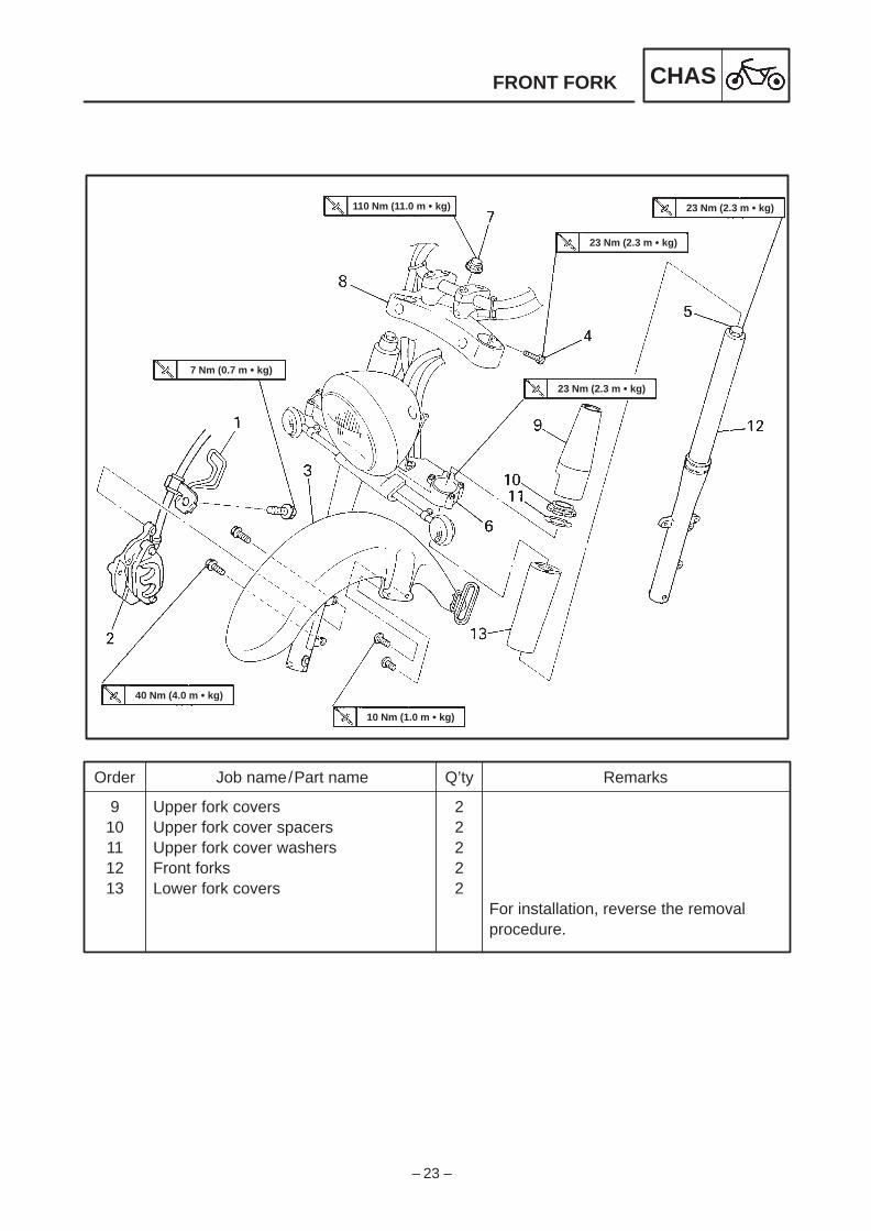
Order Job name/Part name Q’ty Remarks
12345678
Front fork removalFront wheelBrake hose holderBrake caliper assemblyFront fenderUpper bracket boltsCap boltsLower bracket boltsSteering stem nutUpper bracket with handle
11122211
Remove the parts in the order below.Refer to “FRONT WHEEL”
LoosenRefer to “FRONT FORK INSTALLA-TION”.
110 Nm (11.0 m kg)
23 Nm (2.3 m kg)
23 Nm (2.3 m kg)
23 Nm (2.3 m kg)
7 Nm (0.7 m kg)
40 Nm (4.0 m kg)
10 Nm (1.0 m kg)
FRONT FORK CHAS
CHASSISFRONT FORK
– 23 –
Order Job name/Part name Q’ty Remarks
910111213
Upper fork coversUpper fork cover spacersUpper fork cover washersFront forksLower fork covers
22222
For installation, reverse the removalprocedure.
110 Nm (11.0 m kg)
23 Nm (2.3 m kg)
23 Nm (2.3 m kg)
23 Nm (2.3 m kg)
7 Nm (0.7 m kg)
40 Nm (4.0 m kg)
10 Nm (1.0 m kg)
FRONT FORK CHAS

– 24 –
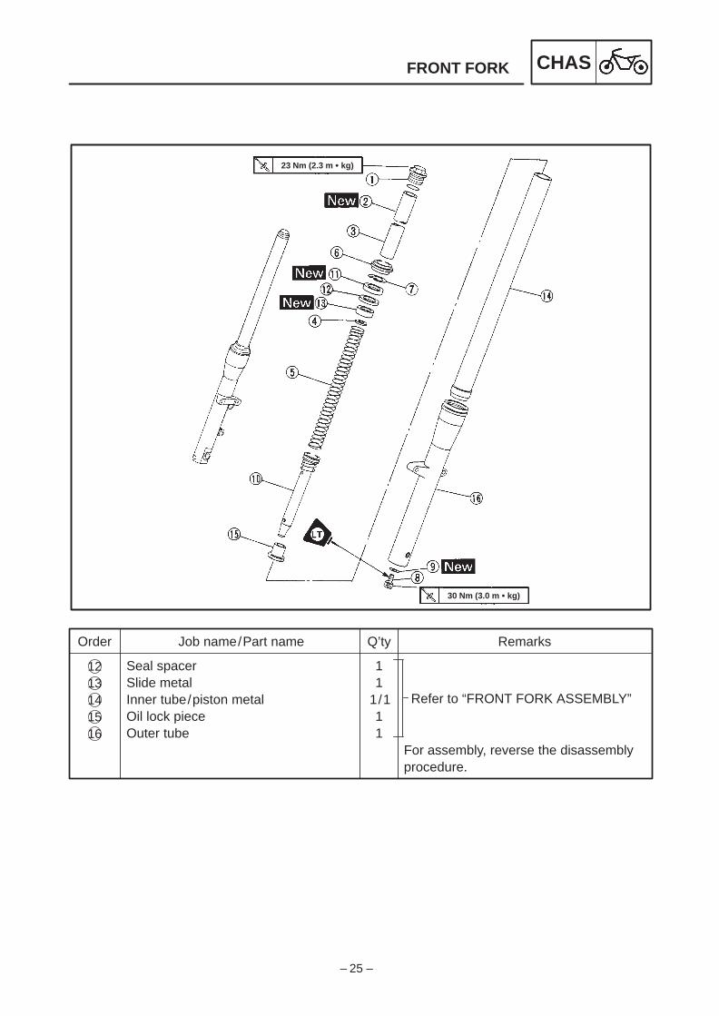
FRONT FORK CHAS
109
Order Job name/Part name Q’ty Remarks
Front fork disassembly
Cap boltO-ringSpacer collarSpring seatFork springDust sealRetaining clipDamper rod boltGasketDamper rod/rebound springOil seal
111111111
1/11
Disassemble the parts in the orderbelow.
Refer to “FRONT FORK DISASSEM-BLY/ASSEMBLY”.
Refer to “FRONT FORK ASSEMBLY”
12345678
11
23 Nm (2.3 m kg)
30 Nm (3.0 m kg)
j
– 25 –
FRONT FORK CHAS
12
Order Job name/Part name Q’ty Remarks
Seal spacerSlide metalInner tube/piston metalOil lock pieceOuter tube
11
1/111
For assembly, reverse the disassemblyprocedure.
Refer to “FRONT FORK ASSEMBLY”13141516
23 Nm (2.3 m kg)
30 Nm (3.0 m kg)

– 26 –
FRONT FORK CHAS
CAUTION:
NOTE:
*************************************
*************************************
CAUTION:
FRONT FORK DISASSEMBLY1. Remove:
Dust seal 1Retaining clip 2(use a slotted-head screwdriver)
Take care not to scratch the inner tube.
2. Remove:Damper rod bolt 1
Loosen the damper rod bolt while holding thedamper rod with the T-handle 2 and the damp-er rod holder 3 .
T-Handle:90890-01326
Damper rod holder:90890-01388
3. Remove:Damper rodRebound spring
4. Remove Inner tube
Removal steps: Hold the fork leg horizontally. Securely clamp the caliper mounting boss of
the outer tube in a vise with soft jaws. Separate the inner tube from the outer tube
by pulling forcefully but carefully on the innertube.
Excessive force will damage the oil sealand/or the slide metal. A damaged oil sealand metal must be replaced.
Avoid bottoming the inner tube into theouter tube during the above procedure, asthe oil lock piece will be damaged.

– 27 –
FRONT FORK CHAS
NOTE:
EB703030
FRONT FORK INSPECTION1. Inspect:
Inner tube 1Outer tube 2Scratches/bends/damage Replace.
Do not attempt to straighten a bent innertube as this may dangerously weaken thetube.
2. Measure:Fork spring length aOver the specified limit Replace.
Fork spring free length (limit):325.9 mm
3. Inspect:Damper rod 1Wear/damage Replace.Contamination Blow out all of the oilpassages with compressed air.
Oil lock piece 2Damage Replace.
4. Inspect:O-ring (cap bolt)Wear/damage Replace.
FRONT FORK ASSEMBLY
When reassembling the front fork, replacethe following parts.*Piston metal*Slide metal*Oil seal*Dust seal
Before reassembly make sure that all thecomponents are clean.

– 28 –
FRONT FORK CHAS
CAUTION:
30 Nm (3.0 mkg)
NOTE:
1. Install:Damper rod 1Rebound springOil lock piece 2 Inner tube 3
Allow the damper rod to slide slowly downthe inner tube until it protrudes from the bot-tom, being careful not to damage the innertube.
2. Lubricate: Inner tube (outer surface)
Recommended lubricant:Yamaha fork oil 10WT orequivalent
3. Install: Inner tube 1(to outer tube 2 )
4. Install:Gasket 1 Damper rod bolt 2
5. Tighten:Damper rod bolt 1
Apply LOCTITE) to the threads of the damperrod holder. Tighten the damper rod bolt whileholding the damper rod with a T-handle 2 and adamper rod holder 3 .
T-handle:90890-01326
Damper rod holder:90890-01388

– 29 –
FRONT FORK CHAS
NOTE:
CAUTION:
NOTE:
6. Install:Slide metal 1 Seal spacerUse the fork seal driver weight 2 andthe adapter 3 .
7. Install:Oil seal 1 Use the fork seal driver weight 2 andthe adapter 3 .
Fork seal driver weight:
90890-01367
Adapter:
90890-01381
Before installing the oil seal, apply lithiumsoap base grease onto the oil seal lips.
Make sure that the numbered side of the oil
seal faces up.
8. Install:Retaining clip 1
Adjust the retaining clip so that it fits into theouter tube groove.
9. Install:Dust seal 1Use the fork seal driver weight.
Fork seal driver weight:
90890-01367

– 30 –
FRONT FORK CHAS
NOTE:
NOTE:
110 Nm (11.0 mkg)
NOTE:
10. Fill:Fork oil
Each fork:507 cm3 (17.8 lmp oz)Yamaha fork oil 10WT or equiv-alent. After filling up, slowlypump the fork up and down todistribute the fork oil.
Oil level a :95 mm(from the top of the inner tubefully compressed and withoutthe fork spring)
Hold the fork in an upright position.
11. Install:Fork spring 1Spring seat 2Spacer collar 3O-ringCap bolt
Before installing the cap bolt, apply grease tothe O-ring.
Temporarily tighten the cap bolt.
FRONT FORK INSTALLATION1. Install:
Lower fork covers 1Front forks Temporarily tighten the lower bracketpinch bolts.
2. Tighten:Upper bracketSteering stem nut
When aligning the fork tubes do not install theupper fork covers.
Make sure that the inner tube end is flush withthe top of the handlebar crown.

– 31 –
FRONT FORK CHAS
23 Nm (2.3 mkg)
23 Nm (2.3 mkg)
110 Nm (11.0 mkg)
23 Nm (2.3 mkg)
3. TightenFront fork pinch bolts (lower) 1
Cap bolts4. Remove:
Steering stem nutUpper bracket
5. Install:Upper fork cover washers 1Upper fork cover spacers 2Upper fork covers 3
6. Instal:Upper bracket 1Steering stem nut 2
7. Tighten:Fron fork pinch bolts (upper)
8. Install:Front fender 1Brake hose holders 2

– 32 –
Refer to “FRONT FORK”.Refer to “HANDLEBAR”.
Disconnect
For installation, reverse the removalprocedure.
Order Job name/Part name Q’ty Remarks
123456789
Steering head removal
Front forksHandlebarHeadlight lens unitLeads (in the headlight body)Front flasher light (left /right)Headlight bodyUpper bracketLock washerUpper ring nutLock washerUpper ring nut
1–
1/1111111
Remove the parts in the order below.Stand the motorcycle on a level surface.
Securely support the motorcycle sothat there is no danger of it falling over.
32 Nm (3.2 m kg)
110 Nm (11.0 m kg)
52 Nm (5.2 m kg)
18 Nm (1.8 m kg)
STEERING HEAD CHAS
STEERING HEAD