ford focus owner's manual - · pdf fileford focus owner's manual. ... under bonnet...
TRANSCRIPT

FORD FOCUS Owner's Manual

The information contained in this publication was correct at the time of going to print. In the interest ofcontinuous development, we reserve the right to change specifications, design or equipment at any timewithout notice or obligation. No part of this publication may be reproduced, transmitted, stored in aretrieval system or translated into any language in any form by any means without our written permission.Errors and omissions excepted.© Ford Motor Company 2012
All rights reserved.Part Number: (CG3568en) 04/2012 20120306142435

IntroductionAbout This Manual...........................................7Symbols Glossary.............................................7Replacement Parts
Recommendation........................................9
At a GlanceAt a Glance........................................................10
Child SafetyChild Seats.........................................................17Child Seat Positioning...................................18Booster Seats...................................................21ISOFIX Anchor Points...................................22Child Safety Locks..........................................23
Occupant protectionPrinciple of Operation...................................25Fastening the seat belts..............................26Seat belt height adjustment......................27Seat belt reminder..........................................27Using seat belts during pregnancy..........28Disabling the passenger airbag................28
Keys and Remote ControlsGeneral Information on Radio
Frequencies.................................................30Programming the remote control............30Changing the remote control
battery............................................................30
LocksLocking and Unlocking.................................33Keyless Entry....................................................35Global Opening and Closing......................37
Door Edge ProtectionPrinciple of Operation..................................39Changing the Door Edge Protector.........39
Engine immobiliserPrinciple of Operation..................................40Coded keys.......................................................40Arming the engine immobiliser................40Disarming the engine immobiliser..........40
AlarmPrinciple of Operation...................................41Arming the alarm...........................................42Disarming the alarm.....................................42
Steering WheelAdjusting the Steering Wheel....................43Audio Control...................................................43Voice Control...................................................44
Wipers and WashersWindscreen Wipers.......................................45Autowipers.......................................................45Windscreen Washers...................................46Rear Window Wiper and Washers..........46Headlamp Washers.......................................47Checking the Wiper Blades........................47Changing the Wiper Blades........................47
LightingLighting Control..............................................49Autolamps........................................................50Automatic Main Beam Control.................50Front Fog Lamps............................................52Rear Fog Lamps..............................................52Adjusting the Headlamps - Vehicles
With: Adaptive Front Lighting/XenonHeadlamps...................................................53
Headlamp Levelling......................................53Hazard Warning Flashers............................53Direction Indicators.......................................54Cornering Lamps............................................54Interior Lamps.................................................55
1
Table of Contents

Removing a Headlamp................................56Changing a Bulb..............................................57Bulb Specification Chart.............................64
Windows and MirrorsPower Windows.............................................65Exterior Mirrors................................................66Electric exterior mirrors................................67Auto-Dimming Mirror...................................68Blind Spot Monitor........................................68
Instrument ClusterGauges.................................................................71Warning Lamps and Indicators.................73Audible Warnings and Indicators.............76
Information DisplaysGeneral Information......................................78Trip Computer.................................................85Personalised Settings..................................85Information Messages.................................86
Climate ControlPrinciple of Operation..................................98Air Vents............................................................98Manual Climate Control..............................99Automatic Climate Control.......................101Heated Windows and Mirrors..................104Electric sunroof.............................................104Auxiliary Heater............................................106
SeatsSitting in the Correct Position.................109Manual Seats.................................................109Head Restraints.............................................110Power Seats - Vehicles With: 6-Way
Power Seats.................................................112Power Seats - Vehicles With: 8-Way
Power Seats.................................................112Rear Seats........................................................113
Heated Seats...................................................114
Convenience featuresInstrument Lighting Dimmer.....................116Clock...................................................................116Cigar Lighter....................................................116Auxiliary Power Points.................................116Cup Holders......................................................117Glasses Holder................................................117Childminder Mirror.........................................117Auxiliary Input Socket..................................117USB Port............................................................117Satellite Navigation Unit Holder..............118Floor Mats........................................................118
Starting and Stopping theEngine
General Information.....................................119Ignition Switch................................................119Steering Wheel Lock....................................119Starting a Petrol Engine.............................120Starting a Petrol Engine - E85.................120Starting a Diesel Engine..............................121Keyless Starting..............................................121Diesel Particulate Filter...............................123Switching Off the Engine...........................124Engine Block Heater....................................124
Start-StopPrinciple of Operation.................................125Using start-stop............................................125
Eco ModePrinciple of Operation.................................127Using Eco mode.............................................127
Fuel and RefuellingSafety Precautions.......................................128Fuel Quality - Petrol....................................128
2
Table of Contents

Fuel Quality - E85........................................128Fuel Quality - Diesel....................................128Catalytic Converter......................................129Fuel filler flap.................................................129Refuelling..........................................................131Refuelling - E85..............................................131Fuel Consumption.........................................131Technical Specifications............................132
TransmissionManual Transmission..................................134Automatic Transmission............................134
BrakesPrinciple of Operation.................................137Hints on Driving With Anti-Lock
Brakes............................................................137Parking Brake..................................................137
Stability ControlPrinciple of Operation.................................138Using Stability Control...............................138Using Stability Control - 2.0L EcoBoost
SCTi (MI4)..................................................139
Hill Start AssistPrinciple of Operation................................140Using hill start assist...................................140
Parking AidsPrinciple of Operation.................................142Parking Aid - Vehicles With: Rear Parking
Aid..................................................................142Parking Aid - Vehicles With: Front and
Rear Parking Aid........................................143
Rear view cameraPrinciple of Operation................................146Rear View Camera.......................................146
Active Park AssistPrinciple of Operation................................149Using active park assist.............................149
Cruise ControlPrinciple of Operation.................................152Using Cruise Control....................................152
Adaptive cruise control(ACC)
Principle of Operation.................................154Using Adaptive Cruise Control................156Forward alert function................................158
Speed LimiterPrinciple of Operation.................................159Using the speed limiter..............................159
Driver AlertPrinciple of Operation................................160Using driver alert..........................................160
Lane Departure WarningPrinciple of Operation.................................162Using lane departure warning.................162
Lane Keeping AidPrinciple of Operation................................164Using the lane keeping aid........................164
Traffic Sign RecognitionPrinciple of Operation................................166Using traffic sign recognition...................166
Active City StopPrinciple of Operation................................168Using Active City Stop................................168Using Active City Stop - 2.0L EcoBoost
SCTi (MI4)..................................................169
3
Table of Contents

Load CarryingGeneral Information....................................170Luggage Anchor Points..............................170Luggage Covers.............................................170Cargo Nets........................................................171Dog Guard........................................................172Roof Racks and Load Carriers..................174
TowingTowing a Trailer..............................................176Towing a Trailer - 2.0L EcoBoost SCTi
(MI4).............................................................176Retractable tow ball....................................176Tow Ball............................................................179
Driving HintsRunning-In.......................................................182Cold Weather Precautions........................182Driving Through Water................................182
Roadside EmergenciesFirst Aid Kit......................................................183Warning Triangle...........................................183
FusesFuse Box Locations.....................................184Changing a Fuse...........................................185Fuse Specification Chart...........................186
Vehicle recoveryTowing Points................................................194Towing the Vehicle on Four Wheels......194
MaintenanceGeneral Information....................................196Opening and Closing the Bonnet...........196Under Bonnet Overview - 1.0L
EcoBoost.....................................................198Under Bonnet Overview - 1.6L
Duratec-16V (Sigma).............................199
Under Bonnet Overview - 1.6L EcoBoostSCTi (Sigma)...........................................200
Under Bonnet Overview - 2.0L EcoBoostSCTi (MI4)..................................................201
Under Bonnet Overview - 2.0LDuratec-HE (MI4)...................................202
Under Bonnet Overview - 1.6LDuratorq-TDCi (DV) Diesel.................204
Under Bonnet Overview - 2.0LDuratorq-TDCi (DW) Diesel................205
Engine Oil Dipstick - 1.0L EcoBoost......206Engine Oil Dipstick - 1.6L Duratec-16V
(Sigma)......................................................206Engine Oil Dipstick - 1.6L EcoBoost SCTi
(Sigma)......................................................206Engine Oil Dipstick - 2.0L EcoBoost SCTi
(MI4)............................................................206Engine Oil Dipstick - 2.0L Duratec-HE
(MI4)............................................................207Engine Oil Dipstick - 1.6L Duratorq-TDCi
(DV) Diesel/2.0L Duratorq-TDCi (DW)Diesel............................................................207
Engine Oil Check..........................................207Engine Coolant Check...............................208Brake and Clutch Fluid Check................209Washer Fluid Check....................................209Technical Specifications..........................209
Vehicle CareCleaning the Exterior...................................213Cleaning the Interior....................................214Repairing Minor Paint Damage...............214
Vehicle batteryJump-Starting the Vehicle........................215Changing the Vehicle Battery..................216Battery connection points.........................216
Wheels and TyresGeneral Information.....................................217Changing a Road Wheel.............................217Temporary Mobility Kit................................221
4
Table of Contents

Tyre Care.........................................................225Using Winter Tyres......................................225Using Snow Chains.....................................225Using Snow Chains - 2.0L EcoBoost SCTi
(MI4)............................................................226Tyre Pressure Monitoring System..........226Technical Specifications............................227
Vehicle identificationVehicle Identification Plate......................232Vehicle Identification Number................233
Capacities and Specific-ations
Technical Specifications...........................234
Audio introductionImportant audio information..................239
Audio unit overviewAudio unit overview....................................240
Audio System SecuritySecurity code................................................246
Audio unit operationOn/off control...............................................247Sound button................................................247Waveband button........................................247Station tuning control................................247Station preset buttons..............................248Autostore control........................................248Traffic information control.......................248
Audio unit menusAutomatic volume control.......................250Digital signal processing (DSP).............250News broadcasts.........................................250Alternative frequencies.............................250Regional mode (REG).................................251
Compact Disc PlayerCompact disc playback.............................252Track selection..............................................252Fast forward/reverse..................................252Shuffle/random............................................252Repeat compact disc tracks....................252Compact disc track scanning..................253MP3 file playback........................................253MP3 display options...................................253Ending compact disc playback..............254
Auxiliary input (AUX IN)socket
Auxiliary input (AUX IN) socket..............255
Audio TroubleshootingAudio troubleshooting...............................256
TelephoneGeneral Information....................................257Bluetooth setup............................................257Telephone setup...........................................257Telephone controls.....................................258Using the telephone...................................258
Voice controlPrinciple of Operation.................................261Using voice control.......................................261Audio unit commands...............................262Telephone commands..............................269Climate control commands.....................274
ConnectivityGeneral Information....................................277Connecting an external device...............278Connecting an external device - Vehicles
With: Bluetooth........................................278Using a USB device.....................................279Using an iPod................................................280
5
Table of Contents

Navigation introductionGeneral Information...................................282Road Safety...................................................282
Navigation unit overviewNavigation unit overview..........................284Loading the navigation data...................288
Navigation Quick startNavigation Quick start...............................289
System settingsSystem settings............................................292
Navigation systemRoute options menu...................................295Route displays..............................................296
Traffic Message ChannelPrinciple of Operation................................297Using TMC......................................................297
Map updatesMap updates.................................................298
AppendicesType approvals.............................................299Type approvals.............................................299Type approvals.............................................299Type approvals............................................300Type approvals............................................300Type approvals..............................................301Type approvals..............................................301Type approvals..............................................301Electromagnetic compatibility................301
6
Table of Contents

ABOUT THIS MANUALThank you for choosing Ford. Werecommend that you take some time toget to know your vehicle by reading thismanual. The more that you know about it,the greater the safety and pleasure youwill get from driving it.
WARNINGAlways drive with due care andattention when using and operatingthe controls and features on your
vehicle.
Note: This manual describes productfeatures and options available throughoutthe range, sometimes even before they aregenerally available. It may describe optionsnot fitted to your vehicle.Note: Some of the illustrations in thismanual may be used for different models,so may appear different to your vehicle.However, the essential information in theillustrations is always correct.Note: Always use and operate your vehiclein line with all applicable laws andregulations.Note: Pass on this manual when sellingyour vehicle. It is an integral part of thevehicle.
Protecting the EnvironmentYou must play your part in protecting theenvironment. Correct vehicle usage andthe authorised disposal of waste, cleaningand lubrication materials are significantsteps toward this aim.
SYMBOLS GLOSSARYThese are some of the symbols you maysee on your vehicle.
Safety alert
See Owner's Manual
Anti-lock braking system
Avoid smoking, flames or sparks
Battery
Battery acid
Brake fluid - non petroleumbased
Brake system
Cabin air filter
Check fuel cap
Child safety door lock or unlock
Child seat lower anchor
Child seat tether anchor
E71340
Cruise control
7
Introduction
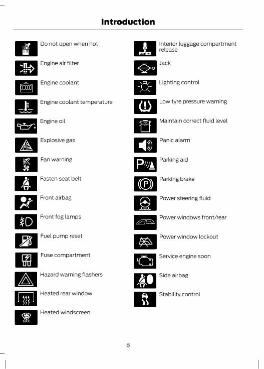
Do not open when hot
Engine air filter
Engine coolant
Engine coolant temperature
Engine oil
Explosive gas
Fan warning
Fasten seat belt
Front airbag
Front fog lamps
Fuel pump reset
Fuse compartment
Hazard warning flashers
Heated rear window
E91392
Heated windscreen
Interior luggage compartmentrelease
Jack
Lighting control
Low tyre pressure warning
Maintain correct fluid level
Panic alarm
E139213
Parking aid
Parking brake
Power steering fluid
Power windows front/rear
Power window lockout
Service engine soon
Side airbag
Stability control
8
Introduction

Windscreen wash and wipe
REPLACEMENT PARTSRECOMMENDATIONYour vehicle has been built to the higheststandards using quality parts. Werecommend that you demand the use ofgenuine Ford and Motorcraft partswhenever your vehicle requires scheduledmaintenance or repair. You can clearlyidentify genuine Ford and Motorcraft partsby looking for the Ford, FoMoCo orMotorcraft branding on the parts or theirpackaging.
Scheduled Maintenance andMechanical RepairsOne of the best ways for you to make surethat your vehicle provides years of serviceis to have it maintained in line with ourrecommendations using parts thatconform to the specifications detailed inthis Owner’s Manual. Genuine Ford andMotorcraft parts meet or exceed thesespecifications.
Collision RepairsWe hope that you never experience acollision but, accidents do happen. GenuineFord replacement collision parts meet ourstringent requirements for fit, finish,structural integrity, corrosion protectionand dent resistance. During vehicledevelopment we validate these partsdeliver the intended level of protection asa whole system. A great way to know forsure you are getting this level of protectionis to use genuine Ford replacementcollision parts.
Warranty on Replacement PartsGenuine Ford and Motorcraft replacementparts are the only replacement parts thatbenefit from a Ford Warranty. Damagecaused to your vehicle as a result of thefailure of non-Ford parts may not becovered by the Ford Warranty. Foradditional information, refer to the termsand conditions of the Ford Warranty.
9
Introduction

Front exterior overview
E133220F E
H
A B
C
D
G
See Locking and Unlocking (page 33). See Keyless Entry (page 35).ASee Automatic Main Beam Control (page 50). See Driver Alert (page 160).See Lane Departure Warning (page 162). See Lane Keeping Aid (page 164).See Traffic Sign Recognition (page 166). See Active City Stop (page 168).
B
See Changing the Wiper Blades (page 47).CSee Maintenance (page 196).DSee Towing Points (page 194).E
10
At a Glance

See Changing a Bulb (page 57).FTyre pressures. See Technical Specifications (page 227).GSee Changing a Road Wheel (page 217).H
Vehicle interior overview
E133222FG
I
H
A B C D
E
See Transmission (page 134).ASee Locking and Unlocking (page 33).BSee Power Windows (page 65). See Electric exterior mirrors (page 67).C
11
At a Glance

See Head Restraints (page 110).DSee Fastening the seat belts (page 26).ESee Rear Seats (page 113).FSee Manual Seats (page 109). See Power Seats (page 112).GSee Parking Brake (page 137).HSee Opening and Closing the Bonnet (page 196).I
Instrument panel overviewLeft-hand drive
E132738
H IGFEDCBA
X W U T S Q P O N M LR K JV
12
At a Glance

Right-hand drive
E132739
HI G B DC FE A
XSU TWK RQO N LMPJ
V
Air vents. See Air Vents (page 98).ADirection indicators. See Direction Indicators (page 54). Main beam. SeeLighting Control (page 49).
B
Left-hand drive vehicles with voice control - Information display control. SeeInformation Displays (page 78).
C
Left-hand drive vehicles without voice control - Information display control.See Information Displays (page 78).
C
Right-hand drive vehicles with voice control - Information and entertainmentdisplay control.
C
Right-hand drive vehicles without voice control - Information display control.See Information Displays (page 78).
C
Instrument cluster. See Gauges (page 71). See Warning Lamps andIndicators (page 73).
D
Left-hand drive vehicles with voice control - Information and entertainmentdisplay control.
E
13
At a Glance

Left-hand drive vehicles without voice control - Audio control. See AudioControl (page 43).
E
Right-hand drive vehicles with voice control - Information display control. SeeInformation Displays (page 78).
E
Right-hand drive vehicles without voice control - Audio control. See AudioControl (page 43).
E
Wiper lever. See Wipers and Washers (page 45).FInformation and entertainment display.GAudio unit. See Audio unit overview (page 240).HDoor lock button. See Locking and Unlocking (page 33).IHazard warning flasher switch. See Hazard Warning Flashers (page 53).JStability control switch. See Using Active City Stop (page 169).KParking aid switch. See Parking Aids (page 142).LActive park assist switch. See Active Park Assist (page 149).MStart-stop switch. See Using start-stop (page 125).NHeated rear window switch. See Heated Windows and Mirrors (page 104).OHeated windscreen switch. See Heated Windows and Mirrors (page 104).PClimate controls. See Climate Control (page 98).QStart button. See Keyless Starting (page 121).RIgnition switch. See Ignition Switch (page 119).SAudio control. See Audio Control (page 43). Voice control. See Voice Control(page 44). Telephone control. See Telephone controls (page 258).
T
Steering wheel adjustment. See Adjusting the Steering Wheel (page 43).UHorn.VCruise control switches. See Using Cruise Control (page 152). Adaptive cruisecontrol (ACC) switches. See Using Adaptive Cruise Control (page 156).Speed limiter switches. See Using the speed limiter (page 159).
W
Lighting control. See Lighting Control (page 49). Front fog lamps. See FrontFog Lamps (page 52). Rear fog lamp. See Rear Fog Lamps (page 52).Headlamp levelling control. See Headlamp Levelling (page 53). Instrumentlighting dimmer. See Instrument Lighting Dimmer (page 116).
X
14
At a Glance

Rear exterior overview
E133221
D
EG
BA C
H F
See Changing the Wiper Blades (page 47).ASee Changing a Bulb (page 57).BSee Changing a Bulb (page 57).CSee Fuel filler flap (page 129).DSee Changing a Road Wheel (page 217).ETyre pressures. See Technical Specifications (page 227).F
15
At a Glance
See Towing Points (page 194).GSee First Aid Kit (page 183). See Warning Triangle (page 183). See TemporaryMobility Kit (page 221). Spare wheel. See Changing a Road Wheel (page217). Jack. See Changing a Road Wheel (page 217). Wheel brace. SeeChanging a Road Wheel (page 217). Towing eye. See Towing Points (page194). Fuel funnel. See Fuel filler flap (page 129).
H
16
At a Glance

CHILD SEATS
E133140
E68916
WARNINGSSecure children that are less than150 centimetres (59 inches) tall in asuitable, approved child restraint, in
the rear seat.Extreme Hazard! Do not use arearward facing child restraint on aseat protected by an air bag in front
of it!Read and follow the manufacturer’sinstructions when you are fitting achild restraint.Do not modify child restraints in anyway.Do not hold a child on your lap whenthe vehicle is moving.
WARNINGSDo not leave unattended children inyour vehicle.If your vehicle has been involved inan accident, have the child restraintschecked by properly trained
technicians.
Note: Mandatory use of child restraintsvaries from country to country.Only child restraints certified toECE-R44.03 (or later) have been testedand approved for use in your vehicle. Achoice of these are available from yourDealer.
Child restraints for different massgroupsUse the correct child restraint as follows:
Baby safety seat
E68918
Secure children that weigh less than 13kilograms (29 pounds) in a rearward facingbaby safety seat (Group 0+) in the rearseat.
17
Child Safety

Child safety seat
E68920
Secure children that weigh between 13 and18 kilograms (29 and 40 pounds) in a childsafety seat (Group 1) in the rear seat.
CHILD SEAT POSITIONING
WARNINGSPlease consult your Dealer for thelatest details relating to Fordrecommended child seats.
WARNINGSExtreme Hazard! Do not use arearward facing child restraint on aseat protected by an air bag in front
of it!When using a child seat with asupport leg, the support leg mustrest securely on the floor.When using a child seat with a seatbelt, make sure that the seat belt isnot slack or twisted.
CAUTIONThe child seat must rest tightlyagainst the vehicle seat. It may benecessary to lift or remove the head
restraint. See Head Restraints (page 110).
Note: When using a child seat on a frontseat, always adjust the front passenger seatto its fully rearwards position. If it provesdifficult to tighten the lap section of the seatbelt without slack remaining, adjust theseatback to the fully upright position andraise the height of the seat. See Seats(page 109).
18
Child Safety

Mass group categories
Seating positions3210+0
22 - 36 kg(49 - 79
lbs)
15 - 25 kg(33 - 55
lbs)
9 - 18 kg(20 - 40
lbs)Up to 13 kg
(29 lbs)Up to 10 kg
(22 lbs)
UF¹UF¹UF¹XXFront passenger seatwith airbag ON
UUUUUFront passenger seatwith airbag OFF
UUUUURear seats
X Not suitable for children in this mass group.U Suitable for universal category child seats approved for use in this mass group.UF¹ Suitable for universal category forward facing child restraints approved for use inthis mass group. However, we recommend that you secure children in a governmentapproved child restraint, in the rear seat.
ISOFIX child seats
Mass group categories
Seating positions10+
Forward facingRear facing
9 - 18 kg (20 - 40 lbs)Up to 13 kg (29 lbs)
Not ISOFIX equippedSize classFront seat
Seat type
A, B, B1, C, D1C, D, E1Size classRear outboard seat ISOFIX
IL, IUF3IL2Seat type
19
Child Safety

Mass group categories
Seating positions10+
Forward facingRear facing
9 - 18 kg (20 - 40 lbs)Up to 13 kg (29 lbs)
Not ISOFIX equippedSize classRear centre seat
Seat type
IL Suitable for particular ISOFIX child restraints systems of the semi-universal category.Please consult child restraints systems suppliers' vehicle recommendation lists.IUF Suitable for ISOFIX forward facing child restraints systems of universal categoryapproved for use in this mass group and ISOFIX size class.1The ISOFIX size class for both universal and semi-universal child restraints systemsis defined by the capital letters A to G. These identification letters are displayed on ISOFIXchild restraints.2At time of publishing the recommended Group O+ ISOFIX baby safety seat is the BritaxRoemer Baby Safe. Please consult your Dealer for the latest details relating to Fordrecommended child seats.3At time of publishing the recommended Group 1 ISOFIX child seat is the Britax RoemerDuo. Please consult your Dealer for the latest details relating to Ford recommended childseats.
20
Child Safety

BOOSTER SEATS
WARNINGSDo not install a booster seat or abooster cushion with only the lapstrap of the seat belt.Do not install a booster seat or abooster cushion with a seat belt thatis slack or twisted.Do not put the seat belt under yourchild’s arm or behind its back.Do not use pillows, books or towelsto boost your child’s height.Make sure that your children sit in anupright position.Secure children that weigh morethan 15 kilograms (33 pounds) butare less than 150 centimetres (59
inches) tall in a booster seat or a boostercushion.
CAUTIONWhen using a child seat on a rear seat,make sure that the child seat reststightly against the vehicle seat. It may
be necessary to lift or remove the headrestraint. See Head Restraints (page 110).
Booster seat (Group 2)
E70710
We recommend that you use a boosterseat that combines a cushion with abackrest instead of a booster cushion only.The raised seating position will allow youto position the shoulder strap of the adultseat belt over the centre of your child’sshoulder and the lap strap tightly acrossits hips.
Booster cushion (Group 3)
E68924
21
Child Safety
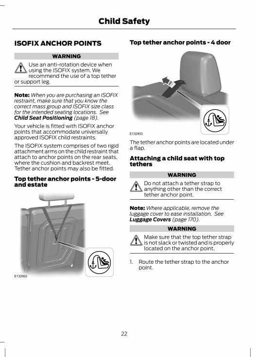
ISOFIX ANCHOR POINTS
WARNINGUse an anti-rotation device whenusing the ISOFIX system. Werecommend the use of a top tether
or support leg.
Note: When you are purchasing an ISOFIXrestraint, make sure that you know thecorrect mass group and ISOFIX size classfor the intended seating locations. SeeChild Seat Positioning (page 18).Your vehicle is fitted with ISOFIX anchorpoints that accommodate universallyapproved ISOFIX child restraints.The ISOFIX system comprises of two rigidattachment arms on the child restraint thatattach to anchor points on the rear seats,where the cushion and backrest meet.Tether anchor points may also be fitted.
Top tether anchor points - 5-doorand estate
E132902
Top tether anchor points - 4 door
E132903
The tether anchor points are located undera flap.
Attaching a child seat with toptethers
WARNINGDo not attach a tether strap toanything other than the correcttether anchor point.
Note: Where applicable, remove theluggage cover to ease installation. SeeLuggage Covers (page 170).
WARNINGMake sure that the top tether strapis not slack or twisted and is properlylocated on the anchor point.
1. Route the tether strap to the anchorpoint.
22
Child Safety

E87145
2. Push the child seat back firmly toengage the ISOFIX lower anchor points.
3. Tighten the tether strap in line with thechild seat manufacturer's instructions.
CHILD SAFETY LOCKS
WARNINGYou cannot open the doors frominside if you have put the child safetylocks on.
Manual child safety locksNote: On vehicles with keyless entry, usethe spare key. See Keyless Entry (page35).
E78298
Left-hand sideTurn anti-clockwise to lock and clockwiseto unlock.
Right-hand sideTurn clockwise to lock and anti-clockwiseto unlock.
Electric child safety locksNote: Pressing the switch will also disablethe rear electric window switches.
23
Child Safety

E124779
24
Child Safety

PRINCIPLE OF OPERATIONAirbags
WARNINGSDo not modify the front of yourvehicle in any way. This couldadversely affect deployment of the
airbags.Extreme Hazard! Do not use arearward facing child restraint on aseat protected by an airbag in front
of it!Wear a seat belt and keep sufficientdistance between yourself and thesteering wheel. Only when you use
the seat belt properly, can it hold you in aposition that allows the airbag to achieveits optimum effect. See Sitting in theCorrect Position (page 109).
Have repairs to the steering wheel,steering column, seats, airbags andseat belts carried out by a properly
trained technician.Keep the areas in front of the airbagsfree from obstruction. Do not affixanything to or over the airbag covers.Do not poke sharp objects into areaswhere airbags are fitted. This coulddamage and adversely affect
deployment of the airbags.Use seat covers designed for seatswith side airbags. Have these fittedby a properly trained technician.
Note: You will hear a loud bang and see acloud of harmless powdery residue if anairbag deploys. This is normal.Note: Only wipe airbag covers with a dampcloth.
Front airbags
E74302
The driver airbag, front passenger airbagand the front seat belt pretensioners willdeploy during significant frontal collisionsor collisions that are up to 30 degrees fromthe left or the right. The airbags will inflatewithin a few thousandths of a second anddeflate on contact with the occupants,thus cushioning forward body movement.During minor frontal collisions, overturns,rear collisions and side collisions, the driverand front passenger airbags will notdeploy.
Side and curtain airbagsDuring significant lateral collisions, onlythe airbags on the side affected by thecollision and the front seat beltpretensioners will deploy. The airbags willinflate within a few thousandths of asecond and deflate on contact with theoccupants, thus providing protection forthe body. The side and curtain airbags willnot deploy during minor lateral collisions,front collisions, rear collisions or overturns.
25
Occupant protection

Side airbags
E72658
Side airbags are fitted inside the seatbackof the front seats. A label indicates thatside airbags are fitted to your vehicle.
Curtain airbags
E75004
Curtain airbags are fitted inside the trimpanels over the front and rear sidewindows. Moulded badges in the B-pillartrim panels indicate that curtain airbagsare fitted to your vehicle.
Seat beltsWARNINGS
Wear a seat belt and keep sufficientdistance between yourself and thesteering wheel. Only when you use
the seat belt properly, can it hold you in aposition to achieve its optimum effect. SeeSitting in the Correct Position (page109).
WARNINGSNever use a seat belt for more thanone person.Use the correct buckle for each seatbelt.Do not use a seat belt that is slackor twisted.Do not wear thick clothing. The seatbelt must fit tightly around your bodyto achieve its optimum effect.Position the shoulder strap of theseat belt over the centre of yourshoulder and position the lap strap
tightly across your hips.
The driver and front passenger seat beltsystems are fitted with a seat beltpretensioner. Seat belt pretensioners havea lower deployment threshold than theairbags. During minor collisions, it ispossible that only the seat beltpretensioners will deploy.
Status after a collision
WARNINGSSeat belts subjected to strain, as aresult of an accident, should berenewed and the anchorages
checked by a properly trained technician.If a seat belt pretensioner has beendeployed the seat belt must berenewed.
FASTENING THE SEAT BELTS
WARNINGInsert the tongue into the buckle untilyou hear a distinct click. You havenot fastened the seat belt properly
if you do not hear a click.
26
Occupant protection

E74124
E85817
Pull the belt out steadily. It may lock if youpull it sharply or if the vehicle is on a slope.Press the red button on the buckle torelease the belt. Let it retract completelyand smoothly.
SEAT BELT HEIGHTADJUSTMENT
E87511
Note: Lifting the slider slightly whilepressing the locking button makes it easierto release the locking mechanism.To raise or lower, press the locking buttonon the adjuster and move as necessary.
SEAT BELT REMINDER
WARNINGThe occupant protection system willonly provide optimum protectionwhen you use the seat belt properly.
The seat belt reminder warninglamp illuminates and an audiblewarning will sound if the driver's
or front seat passenger's seat belt has notbeen fastened and the vehicle exceeds arelatively low speed. It will also illuminateif the driver's or front seat passenger's seatbelt is unfastened when the vehicle ismoving. The audible warning will go offafter a few minutes but the seat beltreminder warning lamp will remain on untilthe driver's or front seat passenger's seatbelt is fastened.
27
Occupant protection

Rear seat belt reminderWARNING
If multiple belts are unfastenedwithin a few seconds of each other,only one audible chime will sound.
Note: Press the OK button on the steeringwheel control to confirm the message.A visual reminder of the seat belt statuswill be shown on the instrument displayonce the engine is started, and once againif any are unfastened when the vehicle ismoving.Fastened seat belts are indicated by a ticksymbol.If a belt is unfastened when the vehicle ismoving, the seat belt status screen will bedisplayed and the relevant seats will behighlighted by an exclamation mark. Anaudible chime will also sound.
Deactivating the seat beltreminderSee your dealer.
USING SEAT BELTS DURINGPREGNANCY
E68587
WARNINGPosition the seat belt correctly foryour safety and that of your unbornchild. Do not use only the lap strap
or the shoulder strap.
Position the lap strap comfortably acrossyour hips and low beneath your pregnantabdomen. Position the shoulder strapbetween your breasts, above and to theside of your pregnant abdomen.
DISABLING THE PASSENGERAIRBAG
WARNINGMake sure that the passenger airbagis disabled when using a rearwardfacing child restraint on the front
passenger seat.
E71313
Fitting the passenger airbagdeactivation switch
WARNINGIf you need to fit a child restraint ona seat protected by an operationalairbag in front of it, have a passenger
airbag deactivation switch fitted. Ask yourdealer for further information.
28
Occupant protection

Note: The key switch is located in the glovecompartment with an airbag deactivationlamp in the overhead console.If the airbag warning lamp illuminates orflashes when you are driving, this indicatesa malfunction. See Warning Lamps andIndicators (page 73). Remove the childrestraint and have the system checkedimmediately.
Disabling the passenger airbag
A BE71312
DisabledAEnabledB
Turn the switch to position A.When you switch the ignition on, check thatthe passenger airbag deactivation warninglamp illuminates.
Enabling the passenger airbagWARNING
Make sure that the passenger airbagis enabled when you are not using achild restraint on the front passenger
seat.
Turn the switch to position B.
29
Occupant protection

GENERAL INFORMATION ONRADIO FREQUENCIES
CAUTIONSThe radio frequency used by yourremote control can also be used byother short distance radio
transmissions (e.g. amateur radios,medical equipment, wireless headphones,remote controls and alarm systems). If thefrequencies are jammed, you will not beable to use your remote control. You canlock and unlock the doors with the key.
Check your vehicle is locked beforeleaving it unattended. This willsafeguard against any potential
malicious frequency blocking.
Note: You could unlock the doors if youpress the buttons on the remote controlunintentionally.The operating range between your remotecontrol and your vehicle varies dependingon the environment.
PROGRAMMING THE REMOTECONTROLYou can programme a maximum of eightremote controls to use with your vehicle(including any supplied with your vehicle).
Programming a new remotecontrol1. Insert the key in the ignition.2. Cycle the key from position 0 to II and
then back to 0 four times within sixseconds.
3. Leave the key in position 0 and pressany button on the remote controlwithin 10 seconds. You will receiveconfirmation via a chime or LED thatprogramming has been successful.
Note: Further remote controls may beprogrammed at this stage.4. Press any button on each additional
remote control within 10 seconds ofeach other.
Reprogramming the unlockingfunctionNote: When you press the unlock buttoneither all the doors are unlocked or only thedriver’s door is unlocked. Pressing the unlockbutton again unlocks all the doors.Press and hold the unlock and lock buttonson the remote key simultaneously for atleast four seconds with the ignition off. Thedirection indicators will flash twice toconfirm the change.To return to the original unlocking function,repeat the process.
CHANGING THE REMOTECONTROL BATTERY
E107998
Make sure that you dispose ofold batteries in anenvironmentally friendly way.
Seek advice from your local authorityregarding recycling.
Remote control with a folding keyblade
E1288092
1
30
Keys and Remote Controls

1. Insert a screwdriver in the positionshown and gently push the clip.
2. Press the clip down to release thebattery cover.
E128810
3. Carefully remove the cover.
E128811
4. Turn the remote control over to removethe battery.
5. Install a new battery (3V CR 2032) withthe + facing upwards.
6. Replace the battery cover.
Remote control without a foldingkey blade
1
2
1
E87964
1. Press and hold the pushbuttons on theedges to release the cover. Carefullyremove the cover.
2. Remove the key blade.
E105362
3
3. Twist a flat bladed screwdriver in theposition shown to separate the twohalves of the remote control.
E119190
4
31
Keys and Remote Controls

4. Carefully insert the screwdriver in theposition shown to open the remotecontrol.
E125860
5
CAUTIONDo not touch the battery contacts orthe printed circuit board with thescrewdriver.
5. Carefully prise out the battery with thescrewdriver.
6. Install a new battery (3V CR 2032) withthe + facing downwards.
7. Assemble the two halves of the remotecontrol.
8. Install the key blade.
32
Keys and Remote Controls

LOCKING AND UNLOCKING
CAUTIONCheck your vehicle is locked beforeleaving it unattended.
Note: Do not leave your keys in the vehicle.
LockingLocking with the keyTurn the top of the key towards the frontof the vehicle.
Locking with the remote controlNote: The driver’s door can be locked withthe key. This needs to be used if the remotecontrol is not functioning.Note: Your vehicle can be locked with a reardoor open. The door will be locked when itis closed.
Press the button.
Double lockingWARNING
Do not activate double locking whenpersons or animals are inside thevehicle. You will not be able to
unlock the doors from the inside if you havedouble locked them.
Note: If you double lock your vehicle whilstinside, switch the ignition on to return thedoor locks to a single locked state.Note: Your vehicle can be double lockedwith a rear door open. The door will bedouble locked when it is closed.Double locking is a theft protection featurethat prevents someone from opening thedoors from the inside.
Double locking with the keyTurn the key to the lock position twicewithin three seconds.
Double locking with the remote controlPress the button twice withinthree seconds.
UnlockingUnlocking with the keyTurn the top of the key towards the rear ofthe vehicle.
Unlocking with the remote controlNote: The driver’s door can be unlockedwith the key. This needs to be used if theremote control is not functioning.Note: If the vehicle remains locked forseveral weeks, the remote control will bedisabled. The vehicle must be unlocked andthe engine started using the key. Unlockingand starting the vehicle once will enable theremote control.
Press the button.
Automatic relockingThe doors will relock automatically if youdo not open a door, the luggagecompartment lid, or turn on the ignitionwithin 45 seconds of unlocking the doorswith the remote control. The doors lockand the alarm will return to its previousstate.
Reprogramming the unlocking functionThe unlocking function may bereprogrammed so that only the driver’sdoor is unlocked ( See Programming theremote control (page 30). ).
33
Locks

Locking and unlockingconfirmationNote: If your vehicle has double locking, thedirection indicators will flash once after youhave activated central locking, followed bytwo further flashes after double locking.When you lock the doors, the directionindicators will flash once.When you double lock the doors, thedirection indicators will flash three times.When you unlock the doors, the directionindicators will flash once.
Locking and unlocking the doorsfrom inside
E102566
Press the button. For itemlocation: See At a Glance (page10).
Luggage compartment lidOpening the luggage compartment lidwith the remote control
Press the button twice withinthree seconds.
Closing the luggage compartment lid
E133536
Locking the doors individually withthe keyNote: If the central locking function fails tooperate, the doors can be individually lockedusing the key in the position shown.
E112203
Left-hand sideTurn clockwise to lock.
Right-hand sideTurn anti-clockwise to lock.
UnlockingNote: If the child safety locks have alsobeen activated, pulling the internal lever willonly deactivate the emergency locking andnot the child safety lock. The doors can onlybe opened using the external door handle.Note: If the doors have been unlocked usingthis method, the doors must be lockedindividually until the central locking functionhas been repaired.Unlock the driver's door using the key. Theother doors can be unlocked individuallyby pulling the interior door handles onthose doors.
34
Locks

KEYLESS ENTRYGeneral information
WARNINGThe keyless entry system may notfunction if the key is close to metalobjects or electronic devices such as
mobile phones.
The passive entry system will not functionif:• The vehicle battery is flat.• The passive key frequencies are
jammed.• The passive key battery is flat.Note: If the passive entry system does notfunction, you will need to use the key bladeto lock and unlock your vehicle.The keyless system allows the driver tooperate the vehicle without the use of akey or remote control.
E78276
Passive locking and unlocking requires avalid passive key to be located within oneof the three external detection ranges.These are located approximately one anda half metres from the driver and frontpassenger door handles and the luggagecompartment lid.
Passive keyThe vehicle can be locked and unlockedwith the passive key. The passive key canalso be used as a remote control. SeeLocking and Unlocking (page 33).
Locking the vehicleWARNING
The vehicle does not lock itselfautomatically. If the locking functionis not activated, the vehicle will
remain unlocked.
Note: The ignition will automatically switchoff when you lock your vehicle from theoutside. This is to prevent the vehicle batteryfrom discharging.Note: Do not grab the door handle.
E87384
Touch a front door handle lock sensor tolock the vehicle.To activate central locking and arm thealarm:• Touch a front door handle lock sensor
once.To activate double locking and arm thealarm:• Touch a front door handle lock sensor
twice within three seconds.Note: There must be clearance betweeneach touch of the door handle.Note: Once activated, the vehicle willremain locked for approximately threeseconds. When the delay period is over, thedoors can be opened again, provided thepassive key is within the respectivedetection range.
35
Locks
Two short flashes of the directionindicators confirms that all the doors andthe luggage compartment lid have beenlocked and that the alarm has been armed.
Luggage compartment lidNote: The luggage compartment lid cannotbe closed and, will pop back up if thepassive key is located inside the vehicle withthe doors locked.Note: If a second valid passive key islocated within the rear exterior detectionrange, the luggage compartment lid can beclosed.
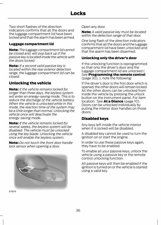
Unlocking the vehicleNote: If the vehicle remains locked forlonger than three days, the keyless systemwill enter an energy-saving mode. This is toreduce the discharge of the vehicle battery.When the vehicle is unlocked while in thismode, the reaction time of the system maybe a little longer than normal. Unlocking thevehicle once will deactivate theenergy-saving mode.Note: If the vehicle remains locked forseveral weeks, the keyless system will bedisabled. The vehicle must be unlockedusing the key blade. Unlocking the vehicleonce will enable the keyless system.Note: Do not touch the front door handlelock sensor when opening a door.
E78278
Open any door.Note: A valid passive key must be locatedwithin the detection range of that door.One long flash of the direction indicatorsconfirms that all the doors and the luggagecompartment lid have been unlocked andthat the alarm has been disarmed.
Unlocking only the driver's doorIf the unlocking function is reprogrammedso that only the driver’s door and theluggage compartment lid are unlocked (See Programming the remote control(page 30). ), note the following:If the driver’s door is the first door which isopened, the other doors will remain locked.All the other doors can be unlocked frominside the vehicle by pressing the unlockbutton on the instrument panel. For itemlocation: See At a Glance (page 10).Doors can be unlocked individually bypulling the interior door handles on thosedoors.
Disabled keysAny keys left inside the vehicle interiorwhen it is locked will be disabled.A disabled key cannot be used to turn theignition on or start the engine.In order to use these passive keys again,they have to be enabled.To enable all your passive keys, unlock thevehicle using a passive key or the remotecontrol unlocking function.All passive keys will then be enabled if theignition is turned on or the vehicle is startedusing a valid key.
36
Locks

Locking and unlocking the doorswith the key blade
1
2
1
E87964
1. Carefully remove the cover.2. Remove the key blade and insert it into
the lock.Note: Only the driver's door handle is fittedwith a lock cylinder.
GLOBAL OPENING ANDCLOSINGYou can also operate the electric windowswith the ignition off via the global openingand global closing function.Note: Global closing will only operate if youhave set the memory correctly for eachwindow. See Power Windows (page 65).
Global opening
E71955
To open all the windows, press and holdthe remote control unlock button for atleast three seconds. Press the lock orunlock button to stop the opening function.
Global closingVehicles without keyless entry
WARNINGTake care when using global closing.In an emergency, press the lock orunlock button immediately to stop.
E71956
37
Locks

To close all the windows, press and holdthe remote control lock button for at leastthree seconds. Press the lock or unlockbutton to stop the closing function. Theanti-trap function is also active duringglobal closing.
Vehicles with keyless entry
E87384
WARNINGTake care when using global closing.In an emergency, touch a doorhandle lock sensor to stop.
Note: Global closing can be activated usingthe driver’s door handle. Global opening andclosing can also be activated using thebuttons on the passive key.To close all the windows, press and holdthe driver’s door handle for at least twoseconds. The anti-trap function is alsoactive during global closing.
38
Locks

PRINCIPLE OF OPERATIONNote: The protective flap may be movedgently out of position when the door is opento allow access for cleaning. Make sure thatthe flap is repositioned correctly otherwisethe flap may not retract when you attemptto close the door.Note: Keep the door edges free fromobstructions such as heavy dirt and snowor ice.The front and rear doors have a retractableplastic flap that will move into positionwhen you open a door. The flap will protectthe door edge from damage that may becaused by contact with other objects andobstacles.
CHANGING THE DOOR EDGEPROTECTORNote: The front and rear door protectorflaps are different lengths. If you install thewrong sized flap it may not operatecorrectly.Note: Open the door and make sure theprotector is extended to change the flap.
E132609
1. Insert a screwdriver in the positionshown and turn the blade to gentlyraise the flap from the holder.
2. Remove the flap.Note: Pull out the flap holder if requiredwhen refitting.3. Install by pushing the flap down onto
the holder.
39
Door Edge Protection

PRINCIPLE OF OPERATIONThe engine immobiliser is a theft protectionsystem that prevents someone fromstarting the engine with an incorrectlycoded key.
CODED KEYSNote: Do not shield your keys with metalobjects. This may prevent the receiver fromrecognising your key as a valid one.Note: Have all of your remaining keyserased and recoded if you lose a key. Askyour dealer for further information. Havereplacement keys recoded together withyour existing keys.If you lose a key, you can obtain areplacement from your Ford Dealer. Ifpossible, provide them with the keynumber from the tag provided with theoriginal keys. You can also obtainadditional keys from your Ford Dealer.
ARMING THE ENGINEIMMOBILISERThe engine immobiliser is armedautomatically a short time after you haveswitched the ignition off.
DISARMING THE ENGINEIMMOBILISERThe engine immobiliser is disarmedautomatically when you switch the ignitionon with a correctly coded key.
40
Engine immobiliser

PRINCIPLE OF OPERATIONAlarm systemYour vehicle may be equipped with one ofthe following alarm systems:• Perimeter alarm.• Perimeter alarm with interior sensors.• Category one alarm with interior
sensors and battery back-up sounder.
Perimeter alarmThe perimeter alarm is a deterrent againstunauthorised access to your vehiclethrough the doors and the bonnet. It alsoprotects the audio unit.
Interior sensors
E129005
WARNINGThe sensors in the interior lamp unitmust not be covered up. Do notactivate the alarm with full guard if
any persons, animals or other movingobjects are inside the vehicle.
The sensors act as a deterrent againstunauthorised intrusion by sensing anymovement within the vehicle.
Battery back-up sounderThe battery back-up sounder is an extraalarm system which will sound a sirenwhen the alarm is triggered. It is armeddirectly when you lock the vehicle. Thesounder has its own battery and will soundan alarm siren even if someonedisconnects the vehicle battery or thebattery back-up sounder itself.
Triggering the alarmOnce armed, the alarm is triggered in anyof the following ways:• If someone opens a door, the tailgate
or the bonnet without a valid key orremote control.
• If someone removes the audio ornavigation system.
• If the ignition is turned to position I, IIor III without a valid key.
• If the interior sensors detect movementwithin the vehicle.
• On vehicles with a battery back-upsounder, if someone disconnects thevehicle battery or the battery back-upsounder itself.
If the alarm is triggered, the alarm horn willsound for 30 seconds and the hazardwarning flasher will flash for five minutes.Any further attempts to perform one of theabove will trigger the alarm again.
Full and reduced guardFull guardFull guard is the standard setting.In full guard, the interior sensors areactivated when you arm the alarm.Note: This may result in false alarms ifanimals or moving objects are inside thevehicle.
41
Alarm

Note: False alarms can also be triggeredby the auxiliary heater See Auxiliary Heater(page 106). If you are using the auxiliaryheater, direct the air flow towards thefootwell.
Reduced guardIn reduced guard, the interior sensors aredeactivated when you arm the alarm.Note: You can set the alarm to reducedguard for the current ignition cycle only. Thenext time you switch on the ignition, thealarm will be reset to full guard.
Ask on ExitYou can set the information display to askyou each time which level of guard youwish to set.If you select Ask on Exit, the messageReduced guard? appears in theinstrument cluster display each time youswitch the ignition off.If you wish to arm the alarm with reducedguard, press the OK button when thismessage appears.If you wish to arm the alarm with full guard,leave the vehicle without pressing the OKbutton.
Selecting full or reduced guardNote: Selecting Reduced does not set thealarm permanently to reduced guard. It setsit to reduced guard only for the currentignition cycle. If you regularly set the alarmto reduced guard, select Ask on Exit.You can select full or reduced guard usingthe information display. See GeneralInformation (page 78).
Information messagesSee Information Messages (page 86).
ARMING THE ALARMTo arm the alarm, lock the vehicle. SeeLocks (page 33).
DISARMING THE ALARMVehicles without keyless entryPerimeter alarmDisarm and silence the alarm by unlockingthe doors with the key and switching theignition on with a correctly coded key, orunlocking the doors or the luggagecompartment lid with the remote control.
Category one alarmDisarm and silence the alarm by unlockingthe doors with the key and switching theignition on with a correctly coded keywithin 12 seconds, or unlocking the doorsor the luggage compartment lid with theremote control.
Vehicles with keyless entryNote: A valid passive key must be locatedwithin the detection range of that door forkeyless entry. See Keyless Entry (page 35).
Perimeter alarmDisarm and silence the alarm by unlockingthe doors and switching the ignition on, orunlocking the doors or the luggagecompartment lid with the remote control.
Category one alarmDisarm and silence the alarm by unlockingthe doors and switching the ignition onwithin 12 seconds, or unlocking the doorsor the luggage compartment lid with theremote control.
42
Alarm

ADJUSTING THE STEERINGWHEEL
WARNINGNever adjust the steering wheelwhen the vehicle is moving.
Note: Make sure that you are sitting in thecorrect position. See Sitting in the CorrectPosition (page 109).
1
2
2
E95178
3E95179
WARNINGMake sure that you fully engage thelocking lever when returning it to itsoriginal position.
AUDIO CONTROLSelect the required source on the audiounit.The following functions can be operatedwith the remote control:
Type 1
E129462
BD
C
AE
Volume upASeek up or nextBVolume downCSeek down or previousDModeE
Press the mode button to select the audiosource.
43
Steering Wheel

Type 2
E129463
C
D
A
B
Volume upASeek up or nextBVolume downCSeek down or previousD
Seek, next or previousPress the seek button to:• tune the radio to the next or previous
stored preset• play the next or the previous track.Press and hold the seek button to:• tune the radio to the next station up or
down the frequency band• seek through a track.
VOICE CONTROL
E129464
Pull the button to select or deselect voicecontrol. See Voice control (page 261).
44
Steering Wheel

WINDSCREEN WIPERS
E128444
A
C
D
B
Single wipeAIntermittent wipe or autowipersBNormal wipeCHigh speed wipeD
Intermittent wipe
C
A B
E128445
Short wipe intervalAIntermittent wipeBLong wipe intervalC
The rotary control can be used to adjustthe intermittent wipe interval.
Automatic wiper systemSome models without autowipers arefitted with a speed-dependent front screenwiper system.When the vehicle is slowed to walkingspeed or is brought to a standstill, thewiper speed will automatically switch tothe next lower wiper speed setting.When the vehicle speed is increased, thewiper speed will return to themanually-chosen setting.Moving the wiper lever when the system isoperating will switch off the system.If the vehicle is again slowed to walkingspeed or is brought to a standstill, thesystem is reactivated.
AUTOWIPERS
CAUTIONSDo not switch autowipers on in dryweather conditions. The rain sensoris very sensitive and the wipers may
operate if dirt, mist or flies hit thewindscreen.
Replace the wiper blades as soon asthey begin to leave bands of waterand smears. If you do not replace
them, the rain sensor will continue todetect water on the windscreen and thewipers will operate, even though themajority of the windscreen is dry.
Fully defrost the windscreen in icyconditions before you switchautowipers on.Switch autowipers off before youenter a car wash.
Note: If autolamps have been switched onin conjunction with autowipers, dippedheadlamps will illuminate automaticallywhen the rain sensor activates thewindscreen wipers continuously.
45
Wipers and Washers

C
A B
E128445
High sensitivityAOnBLow sensitivityC
If you switch autowipers on, the wipers willnot cycle until water is detected on thewindscreen. The rain sensor will thencontinuously measure the amount of wateron the windscreen and adjust the speedof the wipers automatically.Adjust the sensitivity of the rain sensorusing the rotary control. With lowsensitivity, the wipers will operate whenthe sensor detects a lot of water on thewindscreen. With high sensitivity, thewipers will operate if the sensor detects asmall amount of water on the windscreen.
WINDSCREEN WASHERS
E129188
WARNINGDo not operate the washer for morethan 10 seconds at a time, and neverwhen the reservoir is empty.
Whilst the lever is pulled towards thesteering wheel the washer will work inconjunction with the wipers.After releasing the lever, the wipersoperate for a short time.
REAR WINDOW WIPER ANDWASHERSIntermittent wipe
E129193
A B
Intermittent wipeALow speed wipeB
Press the button at the end of the lever tochange between off, intermittent and lowspeed.
46
Wipers and Washers

Reverse gear wipeThe rear wiper will be activatedautomatically when selecting reverse gearif the rear wiper is not already switched onand the front wiper is operating.
Rear window washer
E129194
WARNINGDo not operate the washer for morethan 10 seconds at a time, and neverwhen the reservoir is empty.
While the lever is pushed away from thesteering wheel the washer will work inconjunction with the wipers.After releasing the lever, the wipersoperate for a short time.
HEADLAMP WASHERSThe headlamp washers will operate withthe windscreen washers when theheadlamps are on.Note: To stop the washer fluid reservoiremptying quickly, the headlamp washerswill not operate every time that you use thewindscreen washers.
CHECKING THE WIPERBLADES
E66644
Run the tip of your fingers over the edge ofthe blade to check for roughness.Clean the wiper blade lips with waterapplied with a soft sponge.
CHANGING THE WIPERBLADESWindscreen wiper blades
CAUTIONSSet the windscreen wipers in theservice position to change the wiperblades.You can use the service position inwinter to provide easier access to thewiper blades for freeing them from
snow and ice. The windscreen wipers willreturn to their normal position as soon asyou switch on the ignition so make surethat the outside of the windscreen is freefrom snow and ice before you switch onthe ignition.
47
Wipers and Washers

Service position
E75184
E129986A
Switch off the ignition and move the wiperlever to position A within three seconds.Release the lever when the windscreenwipers have moved to the service position.
Changing the windscreen wiper bladesSet the windscreen wipers in the serviceposition and lift the wiper arms.
E728991
2
Install in the reverse order.Note: Make sure that the wiper blade locksinto place.
Rear window wiper blade1. Lift the wiper arm.
2
3
4
E86456
2. Position the wiper blade at right anglesto the wiper arm.
3. Disengage the wiper blade from thewiper arm.
4. Remove the wiper blade.Note: Make sure that the wiper blade locksinto place.5. Install in the reverse order.
48
Wipers and Washers

LIGHTING CONTROLLighting control positions
E132706
A CB
OffASide and tail lampsBHeadlampsC
Parking lampsWARNING
Prolonged use of the parking lampswill discharge the battery.
Switch off the ignition.
Both sidesTurn the lighting control switch to positionB.
One side
E130139
A
B
Right-hand sideALeft-hand sideB
Main and dipped beam
E130140
Push the lever forward to switch betweenmain and dipped beam.
Headlamp flasherPull the lever slightly towards the steeringwheel.
49
Lighting

Home safe lightingSwitch the ignition off and pull thedirection indicator lever towards thesteering wheel to switch the headlampson. You will hear a short tone. Theheadlamps will go off automatically afterthree minutes with any door open, or 30seconds after the last door has beenclosed.The home safe lights can be cancelled byeither pulling the direction indicator levertowards the steering wheel again or byturning the ignition switch ON.
AUTOLAMPS
WARNINGIn severe weather conditions, it maybe necessary to switch yourheadlamps on manually.
Note: If you have switched autolamps on,you can only switch the main beam on whenautolamps has switched the headlamps on.Note: If autolamps have been switched onin conjunction with autowipers, dippedheadlamps will illuminate automaticallywhen the rain sensor activates thewindscreen wipers continuously.
E132707
The headlamps will come on and go offautomatically depending on the ambientlight.The headlamps will remain on for a periodof time after you switch the ignition off.You can adjust the time delay using theinformation display. See InformationDisplays (page 78).
AUTOMATIC MAIN BEAMCONTROL
WARNINGSThe system does not relieve you ofyour responsibility to drive with duecare and attention. A manual
override may be necessary if the systemfails to switch the main beam on or off.
A manual override may be requiredwhen approaching other road userssuch as cyclists.Do not use the system in fog.
CAUTIONSIn cold and severe weather conditionsthe system may not function. Amanual override may be necessary in
these cases.Reflective road signs may be detectedas oncoming traffic and theheadlamps may be switched to
dipped beam.If the lights of oncoming vehicles arehidden by obstacles (for exampleguard rails) the system may not
deactivate the main beam.Always fit Ford Original Parts whenreplacing headlamp bulbs. Otherbulbs may reduce system
performance.
50
Lighting

CAUTIONSCheck and replace wiper bladesregularly to ensure the camera sensorhas a clear view through the
windscreen. Replacement wiper bladesmust be the correct length.
Note: Keep the windscreen free fromobstructions such as bird droppings, insectsand snow or ice.The system will automatically switch onmain beam if it is dark enough and no othertraffic is present. If it detects anapproaching vehicle’s headlamps or taillamps, or street lighting ahead the systemwill switch off main beam before it candistract other road users. Dipped beamswill remain on.A camera sensor is centrally mountedbehind the windscreen of the vehicle, andmonitors conditions continuously to decidewhen to switch the main beam off and on.Once the system is active the main beamwill switch on if:• It is dark enough to require the use of
main beams and• there is no traffic or street lighting
ahead and• vehicle speed is greater than 40 km/h
(25 mph).The main beam will switch off if:• The ambient light is high enough that
main beam is not required.• An approaching vehicle's headlamps
or tail lamps are detected.• Street lighting is detected.• Vehicle speed falls below 25 km/h (16
mph).• The camera sensor is too hot or
becomes blocked.
Activating the systemSwitch on the system using the informationdisplay and autolamps. See InformationDisplays (page 78). See Autolamps(page 50).
E132707
Turn the switch to the autolamps position.Note: The system may take a short time toinitialise after first switching the ignition on,especially in very dark conditions. The mainbeam will not automatically switch onduring this period.
Setting the system sensitivityThe system has three sensitivity levelswhich can be accessed via the informationdisplay. See Information Displays (page78).The sensitivity determines the speed atwhich the main beam will be restored afterdetected traffic leaves the field of view.
51
Lighting

Manually overriding the system
E133632
Push or pull the lever to switch betweenmain and dipped beam.Note: This is a temporary override and thesystem will return to automatic operationafter a short period.To permanently deactivate the system usethe information display menu or turn thelighting control switch from autolamps toheadlamps.
FRONT FOG LAMPS
WARNINGOnly use the front fog lamps whenvisibility is considerably restricted byfog, snow or rain.
E132709
REAR FOG LAMPS
WARNINGSOnly use the rear fog lamps whenvisibility is restricted to less than 50metres (164 feet).Do not use the rear fog lamps whenit is raining or snowing and visibilityis more than 50 metres (164 feet).
E132710
52
Lighting

ADJUSTING THE HEADLAMPS- VEHICLES WITH: ADAPTIVEFRONT LIGHTING/XENONHEADLAMPSTo adjust the headlamps for driving on theleft or right hand side of the road, see yourdealer.
HEADLAMP LEVELLINGNote: Vehicles with Xenon headlamps areequipped with automatic headlamplevelling.1. Press to release the pop out button.
E132711
1
2
2
2. Rotate the button to the requiredsetting.
3. Push the button to the closed position.You can adjust the level of the headlampbeams according to the vehicle load.
Recommended headlamp levelling switch positions
Switch positionLoad in luggagecompartment
Load
Second row seatsFront seats
0--1-2
1-32
2Max132
3Max1-1
1 See Vehicle identification (page 232).
HAZARD WARNING FLASHERS
E71943
For item location: See At a Glance (page10).
53
Lighting

DIRECTION INDICATORS
E130141
Note: Tap the lever up or down to make thedirection indicators flash only three times.
CORNERING LAMPS
E72898
B
A
B
A
Headlamp beamACornering lamp beamB
54
Lighting
The cornering lamps illuminate the insideof a corner when you are turning.
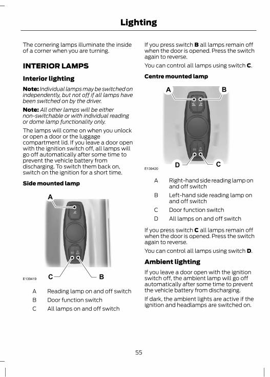
INTERIOR LAMPSInterior lightingNote: Individual lamps may be switched onindependently, but not off if all lamps havebeen switched on by the driver.Note: All other lamps will be eithernon-switchable or with individual readingor dome lamp functionality only.The lamps will come on when you unlockor open a door or the luggagecompartment lid. If you leave a door openwith the ignition switch off, all lamps willgo off automatically after some time toprevent the vehicle battery fromdischarging. To switch them back on,switch on the ignition for a short time.
Side mounted lamp
BCE139419
A
Reading lamp on and off switchADoor function switchBAll lamps on and off switchC
If you press switch B all lamps remain offwhen the door is opened. Press the switchagain to reverse.You can control all lamps using switch C.
Centre mounted lamp
E139420CD
A B
Right-hand side reading lamp onand off switch
A
Left-hand side reading lamp onand off switch
B
Door function switchCAll lamps on and off switchD
If you press switch C all lamps remain offwhen the door is opened. Press the switchagain to reverse.You can control all lamps using switch D.
Ambient lightingIf you leave a door open with the ignitionswitch off, the ambient lamp will go offautomatically after some time to preventthe vehicle battery from discharging.If dark, the ambient lights are active if theignition and headlamps are switched on.
55
Lighting
Type 1Ambient lighting illuminates several areas,for example footwells, cup holders anddoors with a single colour and can beswitched on and off using the informationdisplay menu. See General Information(page 78).Use the instrument lighting dimmerswitches to adjust to the desiredbrightness. See Instrument LightingDimmer (page 116).
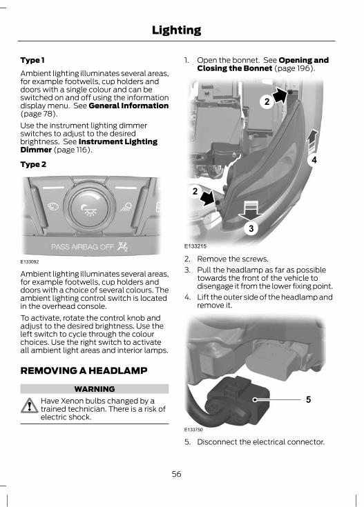
Type 2
E133092
Ambient lighting illuminates several areas,for example footwells, cup holders anddoors with a choice of several colours. Theambient lighting control switch is locatedin the overhead console.To activate, rotate the control knob andadjust to the desired brightness. Use theleft switch to cycle through the colourchoices. Use the right switch to activateall ambient light areas and interior lamps.
REMOVING A HEADLAMP
WARNINGHave Xenon bulbs changed by atrained technician. There is a risk ofelectric shock.
1. Open the bonnet. See Opening andClosing the Bonnet (page 196).
E133215
2
2
4
3
2. Remove the screws.3. Pull the headlamp as far as possible
towards the front of the vehicle todisengage it from the lower fixing point.
4. Lift the outer side of the headlamp andremove it.
E133750
5
5. Disconnect the electrical connector.
56
Lighting

Note: When fitting the headlamp, makesure that you reconnect the electricalconnector properly.Note: When fitting the headlamp, makesure that you fully engage the headlamp inthe lower fixing point.Note: When fitting the headlamp, makesure that the screw is located in theheadlamp moulding before you install it.
CHANGING A BULB
WARNINGSSwitch the lights and the ignition off.
Let the bulb cool down beforeremoving it.Have Xenon bulbs changed by aproperly trained technician. There isa risk of electric shock.
CAUTIONSDo not touch the glass of the bulb.
Only fit bulbs of the correctspecification. See BulbSpecification Chart (page 64).
Note: The following instructions describehow to remove the bulbs. Fit replacementsin the reverse order unless otherwise stated.
HeadlampNote: Remove the covers to gain access tothe bulbs.
E133102
A B C D
Side lampAHeadlamp dipped beamBHeadlamp main beamCDirection indicatorD
Direction indicator1. Remove the headlamp. See
Removing a Headlamp (page 56).
E1331042
3
2. Remove the cover.3. Turn the bulb holder anti-clockwise
and remove it.4. Gently press the bulb into the bulb
holder, turn it anti-clockwise andremove it.
57
Lighting
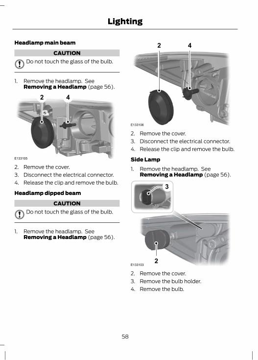
Headlamp main beam
CAUTIONDo not touch the glass of the bulb.
1. Remove the headlamp. SeeRemoving a Headlamp (page 56).
E133105
2 4
2. Remove the cover.3. Disconnect the electrical connector.4. Release the clip and remove the bulb.
Headlamp dipped beam
CAUTIONDo not touch the glass of the bulb.
1. Remove the headlamp. SeeRemoving a Headlamp (page 56).
E133106
2 4
2. Remove the cover.3. Disconnect the electrical connector.4. Release the clip and remove the bulb.
Side Lamp1. Remove the headlamp. See
Removing a Headlamp (page 56).
E1331032
3
2. Remove the cover.3. Remove the bulb holder.4. Remove the bulb.
58
Lighting

Side repeater
E133426
1
1. Carefully remove the cover.
E133427
2. Using a suitable implement release theretaining clip.
E133108
3. Carefully remove the side repeater.
E133109
4. Remove the bulb holder.5. Remove the bulb.
Approach lampCAUTION
When removing the mirror glass, takecare not to break it.
Note: Position the mirror glass as farinwards as possible.
E133110
59
Lighting

1. Insert your fingers into the gap betweenthe mirror housing and the mirror glassand pull gently to remove the mirrorglass.
E133717
2
2. Remove the lamp.
E133718 33. Remove the bulb.
Front fog lamps1. Remove the headlamp. See
Removing a Headlamp (page 56).
2
E133107
3
Note: You cannot separate the fog lampbulb from the bulb holder.2. Disconnect the electrical connector.3. Turn the bulb holder anti-clockwise
and remove it.
Rear lamps - 5 door
E133111
1. Remove the trim panel.
60
Lighting

E133112
2
2. Remove the wing nuts and detach theclip.
3. Remove the lamp.
E133127
4
4. Disconnect the electrical connector.
E133113D
B
C
A
5. Remove the bulb holder.6. Gently press the bulb into the bulb
holder, turn it anti-clockwise andremove it.
A. Brake lampB. Reversing lampC. Tail and fog lampD. Direction indicator
Rear lamps - 4 doorDirection indicator, tail and fog lamp
E133702
1. Remove the trim panel.
61
Lighting

2
E133703
2. Remove the wing nuts and detach theclip.
3. Remove the lamp.
E133713
4
4. Disconnect the electrical connector.
A
B
E133714
5. Remove the bulb holder.
6. Gently press the bulb into the bulbholder, turn it anti-clockwise andremove it.
A. Tail and fog lampB. Direction indicator
Brake and reversing lamp1. Open the luggage compartment lid.
x10 2
E133724
2. Remove the luggage compartment lidtrim.
3
E133725
CAUTIONUnclip the outboard side first.
62
Lighting

3. Remove the wing nut and detach the2 clips.
4. Remove the lamp.
5E133726
5. Disconnect the electrical connector.
E133727
A
B
6. Remove the bulb holder.7. Gently press the bulb into the bulb
holder, turn it anti-clockwise andremove it.
A. Brake lampB. Reversing lamp
Central high mounted brake lampNote: These are not serviceable items,please consult your dealer if they fail.
Number plate lampNote: These are not serviceable items,please consult your dealer if they fail.
Interior lampsVehicles with LED lampsNote: The LED board is not a serviceableitem, please consult your dealer if this fails.
E125092
Luggage compartment lamp,footwell lamp and tailgate lamp
E72784
1. Carefully prise out the lamp.2. Remove the bulb.
63
Lighting

BULB SPECIFICATION CHART
Power (watt)SpecificationLamp
21PY21WFront direction indicator
55H1Headlamp main beam
551H7Headlamp dipped beam
55H1Cornering lamp
55H11Front fog lamp
5W5WSide lamp
5WY5WSide repeater
5W5WApproach lamp
21PY21WRear direction indicator
21/5P21/5WBrake and tail lamp
5W5WTail lamp
21P21WRear fog lamp
16W16WReversing lamp
5W5WLuggage compartment lamp1Fit a replacement with the same rating as the one you have removed.
64
Lighting

POWER WINDOWS
WARNINGDo not operate the electric windowsunless they are free from obstruction.
Note: If you operate the switches oftenduring a short period of time, the systemmight become inoperable for a certain timeto prevent damage due to overheating.Switch on the ignition to operate theelectric windows.
Global opening and closingYou can also operate the electric windowswith the ignition off via the global openingand closing function. See Locks (page33).
Driver's door switchesYou can operate all the windows with theswitches on the door trim panel of thedriver’s door.
E70848
Opening and closing the windowsautomaticallyPress or lift the switch to the second actionpoint and release it completely. Press orlift it again to stop the windows.
Safety switch for rear windowsWARNING
On some vehicles, pressing theswitch will also lock the rear doorsfrom inside. See Child Safety
Locks (page 23).
Note: You can always operate the rearwindows from the driver’s door.
E70850
A switch in the driver’s door disables therear electric window switches.The light in the switch comes on and thelights in the rear window switches go offwhen the rear windows are disabled.
Anti-trap functionWARNING
Careless closing of the windows canoverride the protection function andcause injuries.
65
Windows and Mirrors

The electric windows will stopautomatically while closing and reversesome distance if there is an obstacle in theway.
Overriding the anti-trap function
WARNINGWhile you close the window for thethird time, the anti-trap function isdisabled. Make sure there are no
obstacles in the way of the closing window.
To override this protection function whenthere is a resistance, e.g. in the winter,proceed as follows:1. Close the window twice until it reaches
the resistance and let it reverse.2. Close the window a third time to the
resistance. The anti-trap function isdisabled and you cannot close thewindow automatically. The windowwill override the resistance and you canclose it fully.
3. If the window does not close after thethird attempt, have it checked by anexpert.
Resetting the memory of theelectric windows
WARNINGThe anti-trap function is deactivateduntil you have reset the memory.
After the battery has been disconnectedfrom the vehicle you must reset thememory separately for each window:Note: On vehicles with a convertible top,the roof and doors must be fully closedbefore carrying out the following procedure.1. Lift and hold the switch until the
window is fully closed.2. Release the switch.
3. Lift the switch again for one moresecond.
4. Push and hold the switch until thewindow is fully open.
5. Release the switch.6. Lift and hold the switch until the
window is fully closed.7. Open the window and try to close it
automatically.8. Reset and repeat procedure if the
window does not close automatically.
EXTERIOR MIRRORS
WARNINGDo not overestimate the distance ofthe objects that you see in theconvex mirror. Objects seen in
convex mirrors will appear smaller andfurther away than they actually are.
Manual folding mirrorsFoldingPush the mirror towards the door windowglass.
UnfoldingMake sure that you fully engage the mirrorin its support when returning it to itsoriginal position.
66
Windows and Mirrors
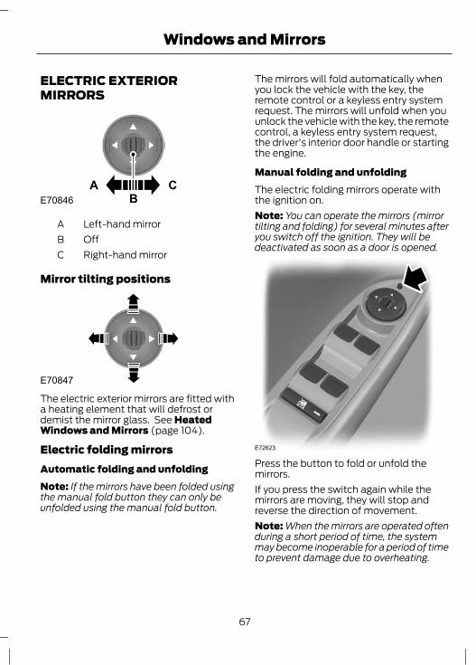
ELECTRIC EXTERIORMIRRORS
A CBE70846
Left-hand mirrorAOffBRight-hand mirrorC
Mirror tilting positions
E70847
The electric exterior mirrors are fitted witha heating element that will defrost ordemist the mirror glass. See HeatedWindows and Mirrors (page 104).
Electric folding mirrorsAutomatic folding and unfoldingNote: If the mirrors have been folded usingthe manual fold button they can only beunfolded using the manual fold button.
The mirrors will fold automatically whenyou lock the vehicle with the key, theremote control or a keyless entry systemrequest. The mirrors will unfold when youunlock the vehicle with the key, the remotecontrol, a keyless entry system request,the driver's interior door handle or startingthe engine.
Manual folding and unfoldingThe electric folding mirrors operate withthe ignition on.Note: You can operate the mirrors (mirrortilting and folding) for several minutes afteryou switch off the ignition. They will bedeactivated as soon as a door is opened.
E72623
Press the button to fold or unfold themirrors.If you press the switch again while themirrors are moving, they will stop andreverse the direction of movement.Note: When the mirrors are operated oftenduring a short period of time, the systemmay become inoperable for a period of timeto prevent damage due to overheating.
67
Windows and Mirrors

AUTO-DIMMING MIRROR
E71028
The auto-dimming mirror will adjustautomatically when hit by glaring lightfrom behind. It will not work when you haveselected reverse gear.
BLIND SPOT MONITORBlind spot information system(BLIS)
WARNINGSThe system is not designed toprevent contact with other vehiclesor objects. The system only provides
a warning to assist you in detectingvehicles in the blind spot zones. Thesystem will not detect obstacles,pedestrians, motorcyclists or cyclists.
Do not use the system as areplacement for using the side andrear view mirrors, and looking over
your shoulder before changing lanes. Thesystem is not a replacement for carefuldriving and is only to be used as an aid.
The system is a convenience feature thataids the driver in detecting vehicles thatmay have entered the blind spot zone (A).The detection area is on both sides of thevehicle extending rearwards from theexterior mirrors to approximately 3 metres(10 feet) beyond the bumper. The systemwill alert you if certain vehicles enter theblind spot zone whilst driving.
A
A
E124788
Using the systemThe system displays a yellow indicatorlocated in the exterior mirrors.
E124736
Note: Both indicators will illuminate brieflywhen you switch the ignition on to confirmthat the system is operational.Note: On vehicles with automatictransmission, the system is active only in S,D and N.The system is only active when you exceed10 km/h (6 mph). The system istemporarily deactivated when you selectreverse gear.
System detection and alertsThe system will trigger the alert for vehiclesthat enter the blind spot zone from the rearor merge from the side. Vehicles that youpass, or vehicles that enter the blind spotzone from the front, will only trigger thealert after the vehicle has remained in theblind spot zone for a short period of time.
68
Windows and Mirrors

Note: Vehicles that pass through the blindzone quickly (typically less than 2 seconds)will not trigger the alert.The system consists of two radar sensorseach located behind the rear wheelshidden behind the bumpers.
CAUTIONSDo not place items such as bumperstickers in this area.Repairs to these areas using body fillerwill affect the performance of thesystem.
E124741
Detection limitationsThere may be certain instances wherevehicles entering and exiting the blind spotzones may not be detected.Instances which may cause non-detection:• Debris build up on the rear bumper
panels in the area of the sensors.• Certain manoeuvring of vehicles
entering and exiting the blind zone.• Vehicles passing through the blind zone
at high speed.• Severe weather conditions.• Several vehicles passing through the
blind zone following each other closely.
False alertsNote: False alerts are temporary and willself correct.There may be certain instances when thesystem will alert with no vehicle present inthe blind zone.Circumstances where false alerts mayoccur:• Road guardrails.• Motorway concrete walls.• Construction areas.• Sharp turns around a building.• Bushes and trees.• Cyclists and motorcyclists.• Coming to a stop with a vehicle directly
behind but very close.
Turning the system on and offNote: The on or off position will remain untilmanually changed.You can turn the system on and off usingthe information display. See InformationDisplays (page 78).When you turn the system off no furtheralerts will be received. The BLIS warningindicator will illuminate. See WarningLamps and Indicators (page 73).
Detection errorsNote: The alert indicator in the mirror willnot illuminate.If the system senses a fault on eithersensor, the system warning symbol willilluminate and remain on. The informationdisplay will confirm the fault and indicatewhether the left or right side is affected.
69
Windows and Mirrors

Blocked sensor
WARNINGPrior to the system recognizing ablocked condition and issuing awarning, the number of missed
objects will increase.
CAUTIONThe sensors may not detect vehiclesin heavy rain or other conditions thatcause disruptive reflections.
Note: Keep the rear bumper areasurrounding the sensors free from dirt, iceand snow.If a sensor becomes blocked the systemperformance may degrade. A blockedsensor message may be displayed.The system will automatically return tonormal operation once two other vehicleshave been detected on both sides.
Trailer towing false alerts
CAUTIONVehicles fitted with a trailer towmodule not approved by us may notcorrectly be detected. Switch the
system off to avoid false alerts. SeeInformation Displays (page 78).
If the vehicle is fitted with a trailer towmodule approved by us, the system willdetect a connected trailer and deactivate.A confirmation message will be shown inthe information display. See InformationMessages (page 86). The BLIS warningindicator will illuminate. See WarningLamps and Indicators (page 73).
70
Windows and Mirrors

GAUGESType 1
BCEF
A
E132065
D
Information display. See Information Displays (page 78).ASpeedometerBEngine coolant temperature gaugeCTripmeter reset buttonDFuel gaugeETachometerF
71
Instrument Cluster

Type 2 and 3
BCDE
A
E130149
Information display. See Information Displays (page 78).ASpeedometerBEngine coolant temperature gaugeCFuel gaugeDTachometerE
2.0L EcoBoost - MI4A B C
E141657
Oil temperature gaugeATurbocharger boost gaugeBOil pressure gaugeC
Engine coolant temperature gaugeAll vehiclesShows the temperature of the enginecoolant. At normal operating temperature,the needle will remain in the centre section.
WARNINGDo not restart the engine until thecause of overheating has beenresolved.
72
Instrument Cluster

If the needle enters the red section, theengine is overheating. Stop the engine,switch the ignition off and determine thecause once the engine has cooled down.See Engine Coolant Check (page 208).
Oil temperature gaugeIndicates the temperature of the engineoil.At normal operating temperature, theneedle remains within the normal area.If it enters the red section, the engine isoverheating. Reduce engine speed as soonas safely possible to allow the engine tocool. If the engine is continued to be drivenat high engine speeds with the needle inthe red section, the engine speed will bereduced automatically to prevent enginedamage.
Turbocharger boost gaugeIndicates the added intake pressureprovided by the turbocharger.
Oil pressure gaugeWARNING
Driving with your oil pressure gaugepointer continuously in the redsection of the scale may damage the
engine.
Note: When the engine is cold, oil pressureclose to 5 bar may be indicated. This isnormal. As the engine warms up, the oilpressure will drop.This gauge indicates engine oil pressureup to a recommended safe maximum of5 bar.During normal driving the indicated oilpressure will vary with engine speed, thepressure rising as engine speed rises anddropping as engine speed drops.
If the engine oil pressure drops below thenormal range, the oil pressure gaugepointer will drop into the red section of thegauge scale and the engine oil pressurewarning lamp in the main instrumentcluster will illuminate. Stop the vehicle assoon as safely possible and switch off theengine immediately. Check the oil level andadd oil if needed. See Engine Oil Check(page 207).
Fuel gaugeThe arrow adjacent to the fuel pumpsymbol indicates on which side of thevehicle the fuel filler cap is located.
WARNING LAMPS ANDINDICATORSThe following warning lamps andindicators illuminate when the ignition isswitched on:• Airbag• ABS• Stability control (ESP)• Low fuel• Brake system• Frost• ESP offIf a warning or indicator lamp does notilluminate when the ignition is switchedon, it indicates a malfunction. Have thesystem checked by properly trainedtechnician.
ABS warning lampIf it illuminates when you aredriving, this indicates amalfunction. You will continue
to have normal braking (without ABS).Have the system checked by a properlytrained technician as soon as possible.
73
Instrument Cluster

Airbag warning lampIf it illuminates when you aredriving, this indicates amalfunction. Have the system
checked by a properly trained technician.
Blind spot monitor indicator
E124823
It will illuminate when thisfeature is deactivated or inconjunction with a message.
See Blind Spot Monitor (page 68). SeeInformation Messages (page 86).
Brake system lampIt illuminates when the parkingbrake is engaged.
WARNINGReduce your speed gradually andstop your vehicle as soon as it is safeto do so. Use your brakes with care.
If it illuminates when you are driving, checkthat the parking brake is not engaged. Ifthe parking brake is not engaged, thisindicates a malfunction. Have the systemchecked by a properly trained technicianimmediately.
Cruise control indicator
E71340
It will illuminate when you haveset a speed using the cruisecontrol system. See Using
Cruise Control (page 152).
Direction indicatorsFlashes during operation. Asudden increase in the rate offlashing warns of a failed
indicator bulb. See Changing a Bulb(page 57).
Engine warning lampIf it illuminates with the enginerunning, this indicates amalfunction. If it flashes when
you are driving, reduce the speed of yourvehicle immediately. If it continues toflash, avoid heavy acceleration ordeceleration. Have the system checked bya properly trained technician immediately.
CAUTIONIf the engine warning lamp illuminatesin conjunction with a message, havethe system checked as soon as
possible.
Forward alert warning indicatorIt will illuminate when thisfeature is switched off or inconjunction with a message.
See Forward alert function (page 158).
Front fog lamp indicatorIt will illuminate when you switchthe front fog lamps on.
Frost warning lampWARNING
Even if the temperature rises toabove +4°C (39°F) there is noguarantee that the road is free of
hazards caused by inclement weather.
It will illuminate and glow amberwhen the outside airtemperature is between +4°C
(39°F) and 0°C (32°F). It will glow redwhen the temperature is below 0°C(32°F).
74
Instrument Cluster

Glow plug indicatorSee Starting a Diesel Engine(page 121).
Headlamp indicatorIt will illuminate when you switchthe headlamp dipped beam orthe side and tail lamps on.
Ignition warning lampIf it illuminates when you aredriving, this indicates amalfunction. Switch off all
unnecessary electrical equipment. Havethe system checked by a properly trainedtechnician immediately.
Lane departure warning indicatorIt will illuminate when thisfeature is switched off or inconjunction with a message.
See Lane Departure Warning (page 162).
Low fuel level warning lampIf it illuminates, refuel as soon aspossible.
Low tyre pressure warning lampSee Tyre Pressure MonitoringSystem (page 226).
Main beam indicatorIt will illuminate when you switchthe headlamp main beam on. Itwill flash when you use the
headlamp flasher.
Message indicatorIt will illuminate when a newmessage is stored in theinformation display. See
Information Messages (page 86).
Oil pressure warning lampCAUTION
Do not resume your journey if itilluminates despite the level beingcorrect. Have the system checked by
a properly trained technician immediately.
If it stays on after starting orilluminates when driving, thisindicates a malfunction. Stop
your vehicle as soon as it is safe to do soand switch the engine off. Check the engineoil level. See Engine Oil Check (page 207).
Rear fog lamp indicatorIt will illuminate when you switchthe rear fog lamps on.
Seat belt reminderSee Seat belt reminder (page27).
Shift indicatorIt will illuminate to inform youthat shifting to a higher gear maygive better fuel economy and
lower CO2 emissions. It will not illuminateduring periods of high acceleration, brakingor when the clutch pedal is pressed.
75
Instrument Cluster

Stability control (ESP) indicatorWhile driving, it flashes duringactivation of the system. Afterswitching on the ignition, if it
does not illuminate or illuminatescontinuously while driving, this indicates amalfunction. During a malfunction, thesystem switches off. Have the systemchecked by a properly trained technicianas soon as possible.
If you switch traction control off,the warning lamp will illuminate.The lamp will go out when you
switch the system back on or when youswitch the ignition off.
Start-stop indicatorIt will illuminate to inform youwhen the engine shuts down orin conjunction with a message.
See Using start-stop (page 125). SeeInformation Messages (page 86).
AUDIBLE WARNINGS ANDINDICATORSSwitching the chimes on and offYou can deactivate certain chimes in theInformation display using the steeringwheel control. For item location: See At aGlance (page 10).To set which chimes should sound:1. Press the left arrow button on the
steering wheel to enter the main menu.2. Highlight Settings with the up and
down arrow buttons and press the rightarrow button.
3. Highlight Chimes and press the rightarrow button.
4. Highlight Information or Warning andpress the OK button to switch thechime on and off.
5. Press the left arrow button to exit themenu. Press and hold the left arrowbutton to return to the main menudisplay.
Automatic transmissionIf position P is not selected, a warningchime will sound when the driver’s door isopened.
FrostWARNING
Even if the temperature rises toabove +4°C (39°F) there is noguarantee that the road is free of
hazards caused by inclement weather.
A warning chime will sound in the followingconditions:• +4°C (39°F) or lower: frost warning.• 0°C (32°F) or lower: danger of icy
roads.
Key outside carVehicles with keyless entryIf the engine is running and a passive keyis no longer detected within the vehicleinterior, a warning chime will sound.
Door openA warning chime will sound when any dooris opened if the vehicle exceeds a relativelylow speed.
Lights onA warning chime will sound if the driver’sdoor is opened with the exterior lightsswitched on and the ignition switched off.
76
Instrument Cluster

Low fuelA warning chime will sound when theremaining fuel is less than approximately6 litres (1.3 gallons).
Seat belt reminderSee Seat belt reminder (page 27).
77
Instrument Cluster

GENERAL INFORMATIONNote: The information display will remainon for several minutes after you switch offthe ignition.Various systems on your vehicle can becontrolled using the information displaycontrols on the steering column.Corresponding information is displayed inthe information display.For detailed instructions on navigation,refer to the appropriate manual.
Device listThe icon changes to show the currentfunction in use.
CD
Radio
Auxiliary input
Phone
Settings
ControlsPress the up and down arrow buttons toscroll through and highlight the optionswithin a menu.Press the right arrow button to enter asub-menu.Press the left arrow button to exit a menu.Hold the left arrow button pressed at anytime to return to the main menu display(escape button).Press the OK button to choose andconfirm a setting.
Menu structure - informationdisplayAll vehiclesYou can access the menu using theInformation display control. For itemlocation: See At a Glance (page 10).
78
Information Displays

Trip Computer Trip odometerDist to emptyInstant fuelAverage fuel
Average speedOutside airAll values
Traction ctrl
Forward alert
BLISCity Stop
Hill start assist
Lane departure
Traffic signs
Driver assist
Deflation detection
SeatbeltsAuto StartStopDriver AlertTraffic signs
Ford EcoMode
Dimming
Auto light rainAmbient light
Auto highbeam
Lighting
AutoManualSet
Gear shiftingAnticipationSpeedFord EcoMode
High SensitivityNormal SensLow SensitivityOff
OnESCSport modeOff
RecognitionSpeed warning
SensitivityIntensity
Hdlamp delay Manual20 seconds40 seconds60 seconds
Information
Settings
BAE133367
Driver alert
OnSensitivity
79
Information Displays

Chimes
Convenience
Park slot found
WarningInformation
Aux heaterPark heater
Alarm
Time 1Time 2OnceHeat now
Full guardReducedAsk on exit
System check
BA
E133368
EnglishDeutschItalianoFrançaisEspañol
PyccкийNederlandsPolski
PortuguêsSvenska
Language
Measure unit
Display
l/100kmMiles/Gallon
Always onOn demandAlways off
Navigation info
Temp unit °Celsius°Fahrenheit
ČeštinaDanskNorsk
80
Information Displays

Menu structure - information andentertainment display
You can access the menu using thebuttons on the audio or navigation unit.
All vehicles
CD
FMFM ASTDAB1DAB2AM
Adaptive volume
iPODUSBBluetooth audioLine in
AM AST
Radio
Auxiliary
Dial numberPhone bookCall listsBluetoothRedialSelect phoneReject all calls
Phone
Audio settingsSoundNav audio mixingDSP settingsDSP equaliserNewsAlt frequencyRDS regionalDAB service linkBluetoothSet timeClock settingsSet dateGPS timeSet time zoneSummertime24-hour mode
Menu
E130532
81
Information Displays

Menu structure - information andentertainment display
You can access the menu using theInformation and entertainment displaycontrol. For item location: See At aGlance (page 10).
82
Information Displays

Vehicles with navigation system
Navigation RouteRoute sections listBlock next section
Destination inputUnblock rt sectn
Unblock rt sectn
EcoFastShortAlways askLeisurelyNormalFast
Driver
Active guidance
City/postcodeStreetDistrictStart guidance
Country
TrafficTMC messagesBlock next sectionRoute sections list
TA
Points of interestNear destinationAlong motorwayPOIs near addressSearch by name
POIs nearby
Home address
Last destinationsChange addressStart guidance
Route options Route
Tour planningStored tours
Store position
New tour
Favourites Favourites A-Z
B CAE130534
83
Information Displays

CD
Special functions
TrailerRoof box
Eco settings
MotorwayTunnelFerry/motorailTollSeasonal roads
Dynamic
Toll sticker
See separate menu structureRadio See separate menu structureAuxiliary See separate menu structurePhone See separate menu structure
Menu Navigation
System infoEnter positionDemo mode
GPS info
DriverEco SettingsDynamicMotorwayTunnelFerry/motorailTollSeasonal roads
Route
Toll sticker
Route options
Arrows on mapNav time displayMap heading upBest contrast
Map contentMap display
B C
CB
A
E130535
84
Information Displays

Audio SettingsClock Settings
Signs/lanesSpeed limitsNav icons in listsHazard spot warning
Clear last destinationClear favouritesDelete home addressClear all
Assistance options
Personal data
Reset all settings
See separate menu structureSee separate menu structure
B C
E130536
TRIP COMPUTERTrip OdometerRegisters the mileage of individualjourneys.
Distance to emptyIndicates the approximate distance thevehicle will travel on the fuel remaining inthe tank. Changes in driving pattern maycause the value to vary.
Instantaneous fuel consumptionIndicates the current average fuelconsumption.
Average fuel consumptionIndicates the average fuel consumptionsince the function was last reset.
Average speedIndicates the average speed calculatedsince the function was last reset.
Outside air temperatureShows the outside air temperature.
OdometerRegisters the total mileage of the vehicle.
Resetting the trip computerTo reset a particular display:1. Highlight Trip Computer with the up
and down arrow buttons and press theright arrow button.
2. Highlight the function to be reset.3. Hold the OK button pressed.
PERSONALISED SETTINGSLanguage settingA choice of 13 languages are available:English, German, Italian, French, Spanish,Russian, Dutch, Polish, Swedish,Portuguese, Czech, Danish and Norwegian.
85
Information Displays

Measure unitsTo toggle between metric and imperialunits, scroll to this display and press theOK button.Toggling the units of measure using thisdisplay will affect the following displays:• Distance to empty.• Average fuel consumption.• Instantaneous fuel consumption.• Average speed.
Temperature unitsTo toggle between metric and imperialunits, scroll to this display and press theOK button.Toggling the temperature units using thisdisplay will affect the following displays:• Outside air temperature.• The temperature display in the
automatic climate control.
Chime deactivationThe following chimes can be deactivated:• Warning messages.• Information messages.
INFORMATION MESSAGESNote: Certain messages may beabbreviated or shortened depending uponwhich cluster type you have.
E130248
Press the OK button to acknowledge andremove some messages from theinformation display. Other messages willbe removed automatically after a shorttime.Certain messages need to be confirmedbefore you can access the menus.
Message indicatorThe message indicatorilluminates to supplement somemessages. It will be red or amber
depending on the severity of the messageand will remain on until the cause of themessage has been rectified.
Some messages will be supplemented bya system specific symbol with a messageindicator.
86
Information Displays

Active City Stop
ActionIndicatorMessage
See (page 168).amberActive City Stop Sensorblocked Clean screen
See (page 168).amberActive City Stop notavailable
See (page 168).-Active City Stop Autobraking
Airbag
ActionMessageindicatorMessage
Have the system checked by a properly trainedtechnician as soon as possible.amberAirbag malfunction
service now
Alarm
ActionMessageindicatorMessage
See Alarm (page 41).amberAlarm triggered checkvehicle
Have the system checked by a properly trainedtechnician.-Alarm malfunction
service required
Automatic main beam control
ActionIndicatorMessage
The front camera sensor has reduced visibility.Clean the windscreen.
amberFront camera low visib-ility Clean screen
The front camera sensor has malfunctioned. Havethis checked as soon as possible.
amberFront camera malfunc-tion Service required
87
Information Displays

Battery and charging system
ActionMessageindicatorMessage
Stop your vehicle as soon as it is safe to do so andswitch off the ignition. Have the system checkedby a properly trained technician as soon aspossible.
redElectrical system overvoltage stop safely
Have the system checked by a properly trainedtechnician as soon as possible.amberBattery low check
handbook
Blind spot monitor
ActionMessageindicatorMessage
See Blind Spot Monitor (page 68).amberBLIS low visibility checkhandbook
Have the system checked by a properly trainedtechnician as soon as possible.amberBLIS: right sensor fault
service required
Have the system checked by a properly trainedtechnician as soon as possible.amberBLIS: left sensor fault
service required
See Blind Spot Monitor (page 68).amberBLIS not availabletrailer attached
Child power lock
ActionMessageindicatorMessage
Have the system checked by a properly trainedtechnician as soon as possible.amberChild lock malfunction
service required
Climate control
ActionIndicatorMessage
See Auxiliary Heater (page 106).amberAuxiliary Heater on
See Auxiliary Heater (page 106).-Auxiliary Heater off
88
Information Displays

Cruise control and Adaptive cruise control (ACC)
ActionIndicatorMessage
See Adaptive cruise control (ACC) (page 154).amberFront radar sensor
blocked check hand-book
See Adaptive cruise control (ACC) (page 154).amberForward Alert not avail-able
See Adaptive cruise control (ACC) (page 154).amberACC not available
Doors open
ActionMessageindicatorMessage
Stop the vehicle as soon as safely possible andclose.redDriver door open
Stop the vehicle as soon as safely possible andclose.redDriver side rear door
open
Stop the vehicle as soon as safely possible andclose.redPassenger door open
Stop the vehicle as soon as safely possible andclose.redPassenger side rear
door open
Stop the vehicle as soon as safely possible andclose.redLuggage compartment
lid open
Stop the vehicle as soon as safely possible andclose. See Opening and Closing the Bonnet(page 196).
redBonnet open
Driver alert
ActionIndicatorMessage
Stop and rest as soon as it is safe to do so.redDriver fatigue warningRest now
Take a rest break soon.amberDriver fatigue warningRest suggested
89
Information Displays

Engine immobiliser
ActionMessageindicatorMessage
Your key has not been recognised. Remove thekey and try again.amberImmobiliser active
check handbook
Have the system checked by a properly trainedtechnician as soon as possible.amberImmobiliser malfunc-
tion service required
Hill start assist
ActionMessageindicatorMessage
Have the system checked by a properly trainedtechnician.amberHill start assist not
available
Keyless entry
ActionMessageindicatorMessage
See Keyless Entry (page 35).redFord KeyFree key notinside car
See Keyless Entry (page 35).amberFord KeyFree key insidevehicle
See Keyless Entry (page 35).-Ford KeyFree Place keyin key holder
See Keyless Entry (page 35).-Ford KeyFree no keydetected
See Changing the remote control battery (page30).-Key battery low replace
soon
See Steering Wheel Lock (page 119).-Steering lock engagedturn steering wheel
90
Information Displays

Lane keeping aid
ActionIndicatorMessage
Have the system checked by a properly trainedtechnician as soon as possible.
amberLane keeping aidmalfunction Servicerequired
Lighting
ActionMessageindicatorMessage
Have the system checked by a properly trainedtechnician as soon as possible.amberHeadlamp malfunction
service required
One or both of the brake lamp bulbs have blown.Check the brake lamp bulbs. See Changing aBulb (page 57).
-Brake lamp bulb fault
One or both of the side or tail lamp bulbs haveblown. Check the side and tail lamp bulbs. SeeChanging a Bulb (page 57).
-Park lamp bulb fault
One or both of the rear fog lamp bulbs have blown.Check the rear fog lamp bulbs. See Changing aBulb (page 57).
-Rear fog lamp bulbfault
One or both of the headlamp dipped beam bulbshave blown. Check the headlamp dipped beambulbs. See Changing a Bulb (page 57).
-Dipped beam bulb fault
One or both of the brake lamp bulbs on your trailerhave blown. Check the brake lamp bulbs on yourtrailer.
-Trailer brake lamp bulbfault
One or both of the direction indicator bulbs onyour trailer have blown. Check the direction indic-ator bulbs on your trailer.
-Trailer turn lamp bulbfault
91
Information Displays
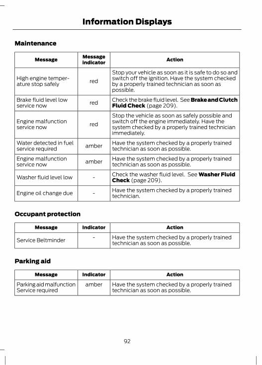
Maintenance
ActionMessageindicatorMessage
Stop your vehicle as soon as it is safe to do so andswitch off the ignition. Have the system checkedby a properly trained technician as soon aspossible.
redHigh engine temper-ature stop safely
Check the brake fluid level. See Brake and ClutchFluid Check (page 209).redBrake fluid level low
service now
Stop the vehicle as soon as safely possible andswitch off the engine immediately. Have thesystem checked by a properly trained technicianimmediately.
redEngine malfunctionservice now
Have the system checked by a properly trainedtechnician as soon as possible.amberWater detected in fuel
service required
Have the system checked by a properly trainedtechnician as soon as possible.amberEngine malfunction
service now
Check the washer fluid level. See Washer FluidCheck (page 209).-Washer fluid level low
Have the system checked by a properly trainedtechnician.-Engine oil change due
Occupant protection
ActionIndicatorMessage
Have the system checked by a properly trainedtechnician as soon as possible.
-Service Beltminder
Parking aid
ActionIndicatorMessage
Have the system checked by a properly trainedtechnician as soon as possible.
amberParking aid malfunctionService required
92
Information Displays
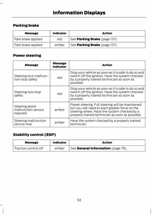
Parking brake
ActionIndicatorMessage
See Parking Brake (page 137).redPark brake applied
See Parking Brake (page 137).amberPark brake applied
Power steering
ActionMessageindicatorMessage
Stop your vehicle as soon as it is safe to do so andswitch off the ignition. Have the system checkedby a properly trained technician as soon aspossible.
redSteering lock malfunc-tion stop safely
Stop your vehicle as soon as it is safe to do so andswitch off the ignition. Have the system checkedby a properly trained technician as soon aspossible.
redSteering loss stopsafely
Power steering. Full steering will be maintainedbut you will need to exert greater force on thesteering wheel. Have the system checked by aproperly trained technician as soon as possible.
amberSteering assistmalfunction servicerequired
Have the system checked by a properly trainedtechnician.amberSteering malfunction
service now
Stability control (ESP)
ActionIndicatorMessage
See General Information (page 78).amberTraction control off
93
Information Displays

Starting the engine
ActionMessageindicatorMessage
See Keyless Starting (page 121).redFord KeyFree switchignition off pressPOWER
See Diesel Particulate Filter (page 123).amberDrive to clean exhaustfilter check handbook
See Diesel Particulate Filter (page 123).amberEngine malfunctionservice now
See Keyless Starting (page 121).-Press brake to start
See Keyless Starting (page 121).-Press clutch to start
See Keyless Starting (page 121).-Press brake and clutchto start
See Starting and Stopping the Engine (page119).-Cranking time
exceeded
See Starting a Diesel Engine (page 121).-Engine preheating
See Diesel Particulate Filter (page 123).-Cleaning exhaust filter
See Diesel Particulate Filter (page 123).-Filter cleaningcomplete
94
Information Displays

Start-stop
ActionMessageindicatorMessage
Switch the ignition off before leaving the vehicleif the system has shut down the engine. See Usingstart-stop (page 125).
redAuto StartStop Switchignition off
Have the system checked by a properly trainedtechnician.amber
Auto StartStopmalfunction servicerequired
The engine needs to be restarted, press the clutchpedal to start. See Using start-stop (page 125).-Auto StartStop Press
clutch to start engine
Select neutral for the system to restart the engine.See Using start-stop (page 125).-Auto StartStop Select
neutral
The system is not functioning. A manual restart isrequired.-Auto StartStop Manual
Start required
95
Information Displays

Transmission
ActionMessageindicatorMessage
Under certain driving conditions it is possible thatthe clutches in the transmission can overheat. Inthese circumstances it is necessary to press thebrake pedal and stop the vehicle to prevent furtheroverheating. Select N (NEUTRAL) or P (PARK)and apply the foot brake and parking brake untilthe transmission has cooled and the messagedisappears from the display. If the vehicle is drivenwith this message active you may experiencevehicle judder as a further overheat warning.
redTransmission too hotpress brake
Have the system checked by a properly trainedtechnician as soon as possible.redTransmission malfunc-
tion service now
The transmission is too hot. In these extremeconditions the transmission will disengage drivein order to prevent damage due to overheating.You will not be able to drive until the transmissionhas cooled. Select N (NEUTRAL) or P (PARK)and apply the foot brake and parking brake untilthe transmission has cooled and the messagedisappears from the display.
redTransmission over-heating stop safely
Under certain driving conditions it is possible thatthe clutches in the transmission can overheat. Inthese circumstances it is necessary to press thebrake pedal and stop the vehicle to prevent furtheroverheating. Select N (NEUTRAL) or P (PARK)and apply the foot brake and parking brake untilthe transmission has cooled and the messagedisappears from the display. If the vehicle is drivenwith this message active you may experiencevehicle judder as a further overheat warning.
amberTransmission too hotpress brake
Some gears may not be available. Have thesystem checked by a properly trained technicianas soon as possible.
amberTransmission limitedfunction check hand-book
At low outside temperatures, after starting theengine, it may take the transmission severalseconds to engage R (REVERSE) or D (DRIVE).Keep the brake pedal depressed until thesemessages disappear from the display.
-Transmission warmingup please wait
96
Information Displays

ActionMessageindicatorMessage
See Automatic Transmission (page 134). SeeStarting and Stopping the Engine (page 119).-Transmission not in
Park select P
See Automatic Transmission (page 134). SeeStarting and Stopping the Engine (page 119).-To start press brake
See Automatic Transmission (page 134).-Press brake pedal
Tyre pressure monitoring system
ActionMessageindicatorMessage
The pressure in one or more tyres has dropped.Check as soon as possible.amberCheck tyre pressures
Permanent malfunction. Have your vehiclechecked by a properly trained technician.amber
Tyre pressure sysmalfunction servicerequired
97
Information Displays
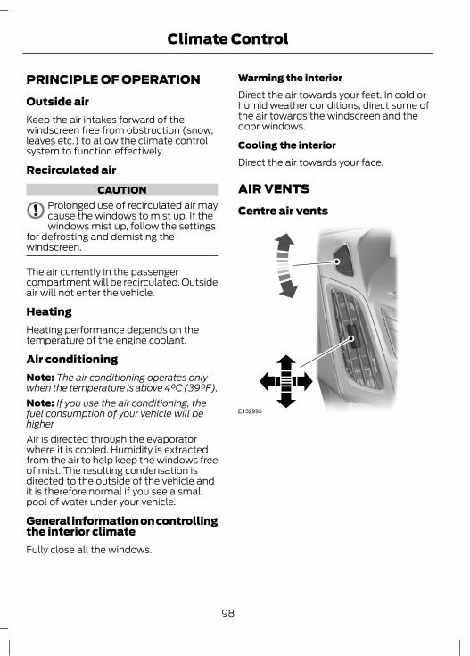
PRINCIPLE OF OPERATIONOutside airKeep the air intakes forward of thewindscreen free from obstruction (snow,leaves etc.) to allow the climate controlsystem to function effectively.
Recirculated airCAUTION
Prolonged use of recirculated air maycause the windows to mist up. If thewindows mist up, follow the settings
for defrosting and demisting thewindscreen.
The air currently in the passengercompartment will be recirculated. Outsideair will not enter the vehicle.
HeatingHeating performance depends on thetemperature of the engine coolant.
Air conditioningNote: The air conditioning operates onlywhen the temperature is above 4°C (39°F).Note: If you use the air conditioning, thefuel consumption of your vehicle will behigher.Air is directed through the evaporatorwhere it is cooled. Humidity is extractedfrom the air to help keep the windows freeof mist. The resulting condensation isdirected to the outside of the vehicle andit is therefore normal if you see a smallpool of water under your vehicle.
General information on controllingthe interior climateFully close all the windows.
Warming the interiorDirect the air towards your feet. In cold orhumid weather conditions, direct some ofthe air towards the windscreen and thedoor windows.
Cooling the interiorDirect the air towards your face.
AIR VENTSCentre air vents
E132995
98
Climate Control

Side air vent
E132996
MANUAL CLIMATE CONTROLAir distribution control
E74660
A
CB D
E
Face levelAFace level and footwellBFootwellCFootwell and windscreenDWindscreenE
You can set the air distribution control toany position between the symbols.
99
Climate Control

Blower
E75470
A
OffANote: If you switch the blower off, thewindscreen may mist up.
Recirculated air
E73059
Press the button to toggle between outsideair and recirculated air.
Heating the interior quickly
E129884
Ventilation
E129885
Set the air distribution control, blower andair vents to suit your requirements.
Air conditioningSwitching the air conditioning on andoff
If you turn the blower off, the airconditioning will turn off. When you turnthe blower on again, the air conditioningwill come on automatically.
Cooling with outside air
E129886
Cooling the interior quickly
E129887
100
Climate Control

With the heater control in this position, theair conditioning and recirculated air willswitch on automatically.You can switch the air conditioning andrecirculated air on and off.
Defrosting and demisting thewindscreen
E129888
When the temperature is above 4°C(39°F), the air conditioning will switch onautomatically. Make sure that the bloweris on. The indicator in the switch willilluminate during defrosting and demisting.
If you move the air distribution control toa position other than windscreen, the A/Cwill remain on.You can switch the air conditioning andrecirculated air on and off while the airdistribution control is set to windscreenIf necessary, switch the heated windowson. See Heated Windows and Mirrors(page 104).
Reducing interior air humidity
E129889
AUTOMATIC CLIMATE CONTROL
E133114
The system controls the temperature,amount and distribution of the air flowautomatically and adjusts them accordingto the driving and weather conditions.Pressing the AUTO button once switcheson the auto mode.
The system in your vehicle is dual-zoneautomatic climate control. When thesystem is in mono mode, all thetemperature zones are linked to the driver'szone. When you switch mono mode off,the dual-zone system allows you to setdifferent temperatures for the driver's andfront passenger's side.
101
Climate Control
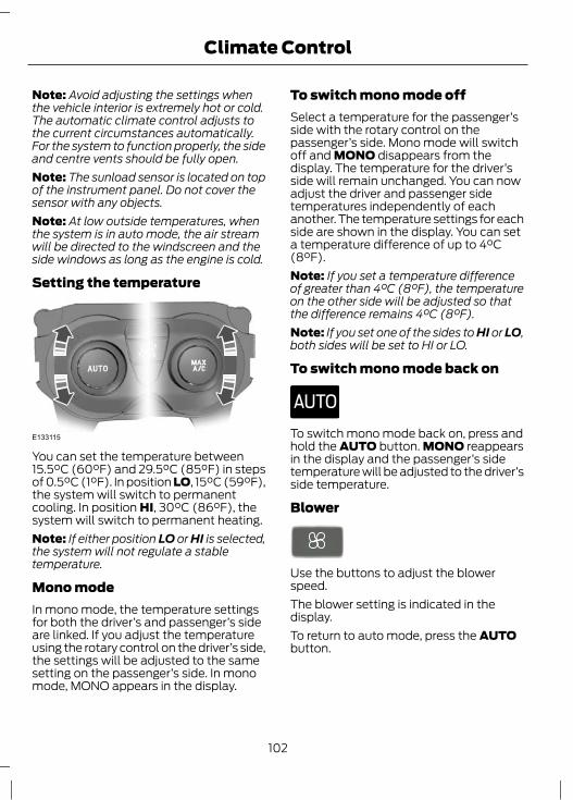
Note: Avoid adjusting the settings whenthe vehicle interior is extremely hot or cold.The automatic climate control adjusts tothe current circumstances automatically.For the system to function properly, the sideand centre vents should be fully open.Note: The sunload sensor is located on topof the instrument panel. Do not cover thesensor with any objects.Note: At low outside temperatures, whenthe system is in auto mode, the air streamwill be directed to the windscreen and theside windows as long as the engine is cold.
Setting the temperature
E133115
You can set the temperature between15.5°C (60°F) and 29.5°C (85°F) in stepsof 0.5°C (1°F). In position LO, 15°C (59°F),the system will switch to permanentcooling. In position HI, 30°C (86°F), thesystem will switch to permanent heating.Note: If either position LO or HI is selected,the system will not regulate a stabletemperature.
Mono modeIn mono mode, the temperature settingsfor both the driver’s and passenger’s sideare linked. If you adjust the temperatureusing the rotary control on the driver’s side,the settings will be adjusted to the samesetting on the passenger’s side. In monomode, MONO appears in the display.
To switch mono mode offSelect a temperature for the passenger’sside with the rotary control on thepassenger’s side. Mono mode will switchoff and MONO disappears from thedisplay. The temperature for the driver’sside will remain unchanged. You can nowadjust the driver and passenger sidetemperatures independently of eachanother. The temperature settings for eachside are shown in the display. You can seta temperature difference of up to 4°C(8°F).Note: If you set a temperature differenceof greater than 4°C (8°F), the temperatureon the other side will be adjusted so thatthe difference remains 4°C (8°F).Note: If you set one of the sides to HI or LO,both sides will be set to HI or LO.
To switch mono mode back on
E133120
To switch mono mode back on, press andhold the AUTO button. MONO reappearsin the display and the passenger’s sidetemperature will be adjusted to the driver’sside temperature.
Blower
Use the buttons to adjust the blowerspeed.The blower setting is indicated in thedisplay.To return to auto mode, press the AUTObutton.
102
Climate Control

Air distributionTo adjust air distribution, press the desiredbutton. Any combination of settings canbe selected simultaneously.
E70308
A B C
FootwellAFace levelBWindscreenC
When you select windscreen defrostingand demisting, A, B and C switch offautomatically and the air conditioningswitches on. Outside air will flow into thevehicle. You cannot select recirculated air.
Cooling the interior quickly
E133122
Windscreen defrosting anddemisting
E91392
Press the windscreen defrosting anddemisting button. Outside air will flow intothe vehicle. Air conditioning isautomatically selected. As long as the airdistribution is set to this position, youcannot select recirculated air.
The blower speed and the temperaturecontrol operate automatically and cannotbe adjusted manually. The blower is set tohigh speed and the temperature to HI.When you select windscreen defrostingand demisting, the heated screens switchon automatically and switch off after ashort time.To return to auto mode, press the AUTObutton.
Switching the air conditioning onand off
E91393
Press the A/C button to switch the airconditioning on and off. A/C OFF appearsin the display when the air conditioning isswitched off.A/C ON appears in the display when theair conditioning is switched on.
Recirculated air
Press the recirculated air button to togglebetween outside air and recirculated air.Note: When the system is in auto mode andthe interior and exterior temperatures arequite hot, the system selects recirculatedair automatically to maximise cooling of theinterior. Once the selected temperature isreached, the system will reselect outside airautomatically.
Switching off the automaticclimate control
E133093
Press the button.
103
Climate Control

When switched off, the heating, ventilationand air conditioning system is switched offand recirculated air is selected.
HEATED WINDOWS ANDMIRRORSHeated windowsUse the heated windows to defrost ordemist the windscreen or rear window.Note: The heated windows operate onlywhen the engine is running.
Heated windscreen
E72506
Heated rear window
E72507
Vehicles without auxiliary heaterIf the ambient temperature is below 5°C(41°F) and the engine coolant is below65°C (149°F), the heated windscreen andheated rear window will switch onautomatically. They will switch offautomatically.
Heated exterior mirrorsElectric exterior mirrors are fitted with aheating element that will defrost or demistthe mirror glass. They will switch onautomatically when you switch the heatedrear window on.
ELECTRIC SUNROOF
WARNINGBefore operating the electric sunroofyou should verify it is free ofobstructions and ensure that children
and/or pets are not in the proximity of thesunroof opening. Failure to do so couldresult in serious personal injury. It is theprimary responsibility of the supervisingadults to never leave a child unattendedin a vehicle and to never leave the keys inan unattended vehicle.
Note: When the switches are operatedoften during a short period of time, thesystem might become inoperable for acertain time to prevent damage due tooverheating.Note: The electric sunroof can also beoperated with the ignition off via the globalopening and global closing function. SeeGlobal Opening and Closing (page 37).There are two ways of opening the sunroof– the rear of the sunroof lifts open or thesunroof opens from the front, sliding backunder the roof. The sunroof opens andcloses whilst the switch is pressed.Switch on the ignition to operate theelectric sunroof.The power sunroof is operated by a switchlocated between the sun visors.
104
Climate Control
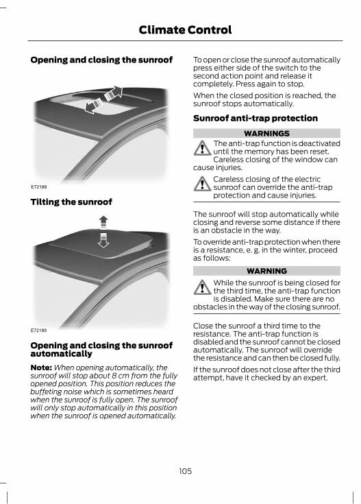
Opening and closing the sunroof
E72188
Tilting the sunroof
E72189
Opening and closing the sunroofautomaticallyNote: When opening automatically, thesunroof will stop about 8 cm from the fullyopened position. This position reduces thebuffeting noise which is sometimes heardwhen the sunroof is fully open. The sunroofwill only stop automatically in this positionwhen the sunroof is opened automatically.
To open or close the sunroof automaticallypress either side of the switch to thesecond action point and release itcompletely. Press again to stop.When the closed position is reached, thesunroof stops automatically.
Sunroof anti-trap protectionWARNINGS
The anti-trap function is deactivateduntil the memory has been reset.Careless closing of the window can
cause injuries.Careless closing of the electricsunroof can override the anti-trapprotection and cause injuries.
The sunroof will stop automatically whileclosing and reverse some distance if thereis an obstacle in the way.To override anti-trap protection when thereis a resistance, e. g. in the winter, proceedas follows:
WARNINGWhile the sunroof is being closed forthe third time, the anti-trap functionis disabled. Make sure there are no
obstacles in the way of the closing sunroof.
Close the sunroof a third time to theresistance. The anti-trap function isdisabled and the sunroof cannot be closedautomatically. The sunroof will overridethe resistance and can then be closed fully.If the sunroof does not close after the thirdattempt, have it checked by an expert.
105
Climate Control

Sunroof safety modeWARNING
The anti-trap function is not activeduring this procedure. Make sure thatthere are no obstacles in the way of
the closing sunroof.
If the system detects a malfunction, itenters a safety mode. The sunroof willmove for only about 0.5 seconds at a timeand then stop again. Close the sunroof bypressing the button again when thesunroof stops moving. When the rear ofthe sunroof is lifted, lift the rear all the wayand then close the sunroof. Have thesystem checked by an expert immediately.
Sunroof relearningWARNING
The anti-trap function is not activeduring this procedure. Make sure thatthere are no obstacles in the way of
the closing sunroof.
In case the sunroof no longer closesproperly, follow this relearning procedure:• Tilt the rear of the sunroof as far as
possible. Release the button.• Press and hold the same button again
for 30 seconds until you see thesunroof move.
• Release the button and immediatelypress and hold it again. The sunroofwill close, open fully and then closeagain. Do not release the button beforethe sunroof has reached the closedposition for the second time.
If the button is not pressed continuously,the relearning function will be interrupted.Start the procedure once more from thebeginning.
AUXILIARY HEATERParking heater
WARNINGSThe parking heater must not beoperated at filling stations, nearsources of combustible vapours or
dust or in enclosed spaces.The parking heater should beswitched on for approximately 10minutes at least once a month all
year round. This prevents the water pumpand heater motor from seizing.
Note: The parking heater will only operateif there is at least 7.5 litres (1.6 gallons) offuel in the fuel tank and the ambienttemperature is below 15°C (59°F). Theheater will not operate if the battery is low.Note: The heating depends on the outsideair temperature.Note: When the parking heater is activated,exhaust fumes may come from under thesides of the vehicle. This is normal.Note: On vehicles with manual climatecontrol the heating of the vehicle interior isdependent on the temperature, airdistribution and blower control settings.The parking heater operates independentlyof the vehicle heater by heating theengine’s coolant circuit. It is fed from thevehicle fuel tank. You can also use it whilethe vehicle is in motion to help the vehicleheater warm up the interior more quickly.Used properly, the parking heater providesthe following benefits:
106
Climate Control

• It preheats the interior of the vehicle.• It keeps the windows clear of ice in the
event of frost and preventscondensation.
• It avoids cold starts and allows theengine to reach operating temperaturesooner.
To prevent the battery from discharging:• Once the parking heater has performed
one heating cycle, the nextprogrammed heating cycle will only becarried out if you have started thevehicle’s engine in between.
• After a heating cycle, drive the vehiclefor at least the period of the heatingcycle.
Programming the parking heaterNote: The programmed time is the time atwhich you wish the vehicle to be warm andready to drive, not the time at which theheater switches on.Note: You must programme the times atleast 70 minutes in advance of the time youwish to set.Note: You must set the time and datecorrectly. See Clock (page 116).To programme the heating times:1. Use the arrow buttons on the steering
wheel to enter the main menu. SeeInformation Displays (page 78).
2. Select the park heater option.
E136301
Once
Time 1Time 2
Heat now
Park Heater
• The two time functions allow you toprogramme up to two heating cyclesfor each day of the week. These timeswill remain stored and the heater willwarm up the vehicle at these times onthese days every week.
• The function once allows you toprogramme one heating cycle for onespecific day.
• The function Heat now automaticallyswitches on the heater.
Programming the functions Time 1 andTime 2
E74468
Tuesday
[07:55]Monday
Wednesday
Time 1
ThursdayFriday
107
Climate Control

1. Use the arrow buttons on the steeringwheel to enter the main menu.
2. Select the first programme time list.3. Highlight the day on which the heater
should warm up the vehicle.4. Press the OK button.5. Continue in the same way to select all
the days on which the heater shouldwarm up the vehicle.
6. To set the time at which the vehicleshould be warmed up, highlight thetime at the top of the display and pressthe OK button. The hours start to flash.
7. Adjust the hours and minutes asnecessary.
You can use the second programme timelist to set a second cycle, for exampledifferent times on different days or twiceon the same day. The programmingprocedure is the same as for the firstprogramme timer..
Deactivating the programmed heater1. Use the arrow buttons on the steering
wheel to enter the main menu.2. Uncheck the active program session.
Programming the heater for a singlecycle1. Select Once and press the right arrow
button.2. Press the OK button and set the
required time and date.3. Press OK to confirm the set time and
date.
Activating the heater manuallyHighlight Heat now and press the OKbutton. A cross appears in the box whenthe heater is activated.To deactivate the heater, uncheck theHeat now function.
Fuel operated heater (dependingon country)
WARNINGThe fuel operated heater must notbe operated at filling stations, nearsources of combustible vapours or
dust or in enclosed spaces.
The fuel operated heater aids in warmingthe engine and the vehicle interior onvehicles with a diesel engine. It is switchedon or off automatically depending on theoutside air temperature and the coolanttemperature, unless you have deactivatedit.To deactivate the fuel operated heater:1. Highlight Aux. Heater and press the
OK button. A cross appears in the boxwhen the heater is activated.
Diesel auxiliary heater (dependingon country)The diesel auxiliary heater (PTC electricalheater) aids in warming the engine and thevehicle interior on vehicles with a dieselengine. It is switched on or offautomatically depending on the outsideair temperature, the coolant temperatureand the alternator load.
108
Climate Control
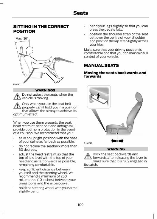
SITTING IN THE CORRECTPOSITION
E68595
WARNINGSDo not adjust the seats when thevehicle is moving.Only when you use the seat beltproperly, can it hold you in a positionthat allows the airbag to achieve its
optimum effect.
When you use them properly, the seat,head restraint, seat belt and airbags willprovide optimum protection in the eventof a collision. We recommend that you:• sit in an upright position with the base
of your spine as far back as possible.• do not recline the seatback more than
30 degrees.• adjust the head restraint so that the
top of it is level with the top of yourhead and as far forwards as possible,remaining comfortable.
• keep sufficient distance betweenyourself and the steering wheel. Werecommend a minimum of 250millimetres (10 inches) between yourbreastbone and the airbag cover.
• hold the steering wheel with your armsslightly bent.
• bend your legs slightly so that you canpress the pedals fully.
• position the shoulder strap of the seatbelt over the centre of your shoulderand position the lap strap tightly acrossyour hips.
Make sure that your driving position iscomfortable and that you can maintain fullcontrol of your vehicle.
MANUAL SEATSMoving the seats backwards andforwards
E130249
WARNINGRock the seat backwards andforwards after releasing the lever tomake sure that it is fully engaged in
its catch.
109
Seats

Adjusting the lumbar support
E78058
Adjusting the height of the driver’sseat
E70730
Adjusting the angle of theseatback
E130250
HEAD RESTRAINTS
WARNINGSRaise the rear head restraint whenthe rear seat is occupied by apassenger.Do not remove the front headrestraints when the front seats arein use.When using a forward facing childrestraint on a rear seat, alwaysremove the head restraint from that
seat.
Adjusting the head restraintAdjust the head restraint so that the topof it is level with the top of your head.
110
Seats
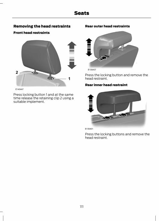
Removing the head restraintsFront head restraints
E140447
21
Press locking button 1 and at the sametime release the retaining clip 2 using asuitable implement.
Rear outer head restraints
E135437
Press the locking button and remove thehead restraint.
Rear inner head restraint
E135401
Press the locking buttons and remove thehead restraint.
111
Seats

POWER SEATS - VEHICLES WITH: 6-WAY POWER SEATS
E78060
POWER SEATS - VEHICLES WITH: 8-WAY POWER SEATS
E141827
112
Seats

Adjust the length of the seatcushion
E78816
Press the locking handle underneath thecushion extension and slide the extensionforward or backward.
REAR SEATS
WARNINGSWhen folding the seatbacks downand up, take care not to get yourfingers caught between the seatback
and seat frame.Make sure that the seats and theseatbacks are secure and fullyengaged in their catches.
Folding the rear seatbacksforwards
WARNINGLower the head restraints. See HeadRestraints (page 110).
1
2
1
E135629
1. Press and hold the unlock buttons.2. Push the seatback forwards.
E135628
3
Note: Make sure that the seat belt is fullytightened into the retractor.3. Place the seat belts in the clips on the
outboard trim.
113
Seats

Folding the seat cushions and therear seatbacks forwards
WARNINGSMake sure the red indicator is notshowing when you engage the seatin the catches.Lower the head restraints. See HeadRestraints (page 110).When inserting your fingers betweenthe seat cushion and seatback, takecare not to get your fingers caught
on the ISOFIX anchor points and bracket.See ISOFIX Anchor Points (page 22).
2
13
2
E135646
Note: Hold the cushion edge to avoid theISOFIX anchor points and brackets.1. Insert your fingers between the seat
cushion and seatback and fold the seatcushion forwards.
2. Press and hold the unlock buttons.3. Push the seatback forwards.
E135647
4
Note: Make sure that the seat belt is fullytightened into the retractor.4. Place the seat belts in the clips on the
outboard trim.
Folding the seatbacks upWARNING
When folding the seatbacks up,make sure that the belts are visibleto an occupant and not caught
behind the seat.
HEATED SEATS
CAUTIONOperating this function with theengine off will drain the battery.
114
Seats
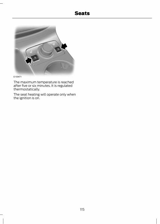
E130471
The maximum temperature is reachedafter five or six minutes. It is regulatedthermostatically.The seat heating will operate only whenthe ignition is on.
115
Seats

INSTRUMENT LIGHTINGDIMMER
E132712
Press repeatedly or press and hold untilthe desired level is reached.Note: If the battery is disconnected,discharged, or a new battery is installed, thedimmer will set the illuminated componentsto the maximum setting automatically.
CLOCKSee Information Displays (page 78).
CIGAR LIGHTER
CAUTIONSIf you use the socket when the engineis not running, the battery maydischarge.Do not hold the cigar lighter elementpressed in.
Note: You can use the socket to power 12volt appliances that have a maximumcurrent rating of 10 Amperes. Use only Fordaccessory connectors or connectorsspecified for use with SAE standard sockets.
E132415
Press the element in to use the cigarlighter. It will pop out automatically.
AUXILIARY POWER POINTS
CAUTIONIf you use the socket when the engineis not running, the battery maydischarge.
Note: You can use the socket to power 12volt appliances that have a maximumcurrent rating of 10 Amperes. Use only Fordaccessory connectors or connectorsspecified for use with SAE standard sockets.
E78056
Auxiliary power sockets are located in thecentre console and in the luggagecompartment.
116
Convenience features

CUP HOLDERS
WARNINGDo not place hot drinks in the cupholders when the vehicle is moving.
Rear seat armrest
E132505
GLASSES HOLDER
E75193
E91508
CHILDMINDER MIRROR
E75192
AUXILIARY INPUT SOCKETYou can find the socket in the glove box orthe centre console. See Auxiliary input(AUX IN) socket (page 255).
USB PORTYou can find the socket in the glove box orthe centre console. See Connectivity(page 277).
117
Convenience features

SATELLITE NAVIGATION UNITHOLDERAdjusting the holder
E112711
1
3
2
1. Unlock.2. Adjust the holder to the desired
position.3. Lock.Note: Make sure that the navigation unitholder is locked in position.
FLOOR MATS
WARNINGWhen using the floor mats, alwaysmake sure the floor mat is properlysecured using the appropriate fixings
and positioned so that it does not interferewith the operation of the pedals.
118
Convenience features

GENERAL INFORMATIONGeneral points on startingIf the battery has been disconnected thevehicle may exhibit some unusual drivingcharacteristics for approx. 8 kilometres (5miles) after reconnecting the battery.This is because the engine managementsystem must realign itself with the engine.Any unusual driving characteristics duringthis period may be disregarded.
Starting the engine by towing orpushing
WARNINGTo prevent damage you must notpush or tow start your vehicle. Usebooster cables and a booster battery.
See Jump-Starting the Vehicle (page215).
IGNITION SWITCH
WARNINGNever return the key to position 0 orI when the vehicle is in motion.
E72128
0 The ignition is off.I The ignition and all main electrical circuitsare disabled.Note: Do not leave the ignition key in thisposition for too long to avoid dischargingthe battery.
II The ignition is switched on. All electricalcircuits are operational. Warning lampsand indicators illuminate. This is the keyposition when driving. You must also selectit when being towed.III The starter motor is activated. Releasethe key as soon as the engine starts.
STEERING WHEEL LOCK
WARNINGAlways check that the steering isunlocked before attempting to moveyour vehicle.
Vehicles without keyless startingTo activate the steering wheel lock;1. Remove the key from the ignition
switch.2. Turn the steering wheel.
Vehicles with keyless startingNote: The steering wheel lock will notactivate when the ignition is on or thevehicle is moving.Your vehicle has an electronicallycontrolled steering wheel lock. Thisoperates automatically.The steering wheel lock will activate aftera short period of time once you haveparked your vehicle and the passive key isoutside of the vehicle, or when you lock thevehicle. See Keyless Entry (page 35).
Deactivating the steering wheel lockSwitch the ignition on, or:Vehicles with automatic transmission• Press the brake pedal.Vehicles with manual transmission• Press the clutch pedal.
119
Starting and Stopping the Engine

STARTING A PETROL ENGINENote: You can only operate the starter fora limited period of time, for example 10seconds. The number of start attempts islimited to approximately six. If you exceedthis limit, the system will not allow you totry again until a period of time has elapsed,for example 30 minutes.
Cold or hot engineVehicles with manual transmissionNote: Do not touch the accelerator pedal.Note: Releasing the clutch pedal duringengine start may stop the engine crankingand return to ignition on.1. Fully depress the clutch pedal.2. Start the engine.
Vehicles with automatic transmissionNote: Do not touch the accelerator pedal.Note: Releasing the brake pedal duringengine start may stop the engine crankingand return to ignition on.1. Move the transmission selector lever
to position P or N.2. Fully depress the brake pedal.3. Start the engine.
All vehiclesIf the engine does not start, wait for a shortperiod and try again.If the engine does not start after threeattempts, wait 10 seconds and follow theflooded engine procedure.If you have difficulty starting the enginewhen the temperature is below -25°C(-13°F), press the accelerator pedal to themid-way point of its travel and try again.
Flooded engineVehicles with manual transmission1. Fully depress the clutch pedal.2. Fully depress the accelerator pedal and
hold it there.3. Start the engine.
Vehicles with automatic transmission1. Move the transmission selector lever
to position P or N.2. Fully depress the accelerator pedal and
hold it there.3. Fully depress the brake pedal.4. Start the engine.
All vehiclesIf the engine does not start, repeat the coldor hot engine procedure.
Engine idle speed after startingThe speed at which the engine idlesimmediately after starting will varydepending on the engine temperature.The idle speed is automatically increasedwhen the engine is cold this is to heat thecatalytic converter. This keeps the vehicleemissions to an absolute minimum.The idle speed will slowly decrease to thenormal level as the catalytic converterwarms up.
STARTING A PETROL ENGINE- E85For general information on starting a petrolengine. See Starting a Petrol Engine(page 120).
120
Starting and Stopping the Engine

Starting at low ambienttemperaturesWhen the temperature is lower than -10°C(14°F) and the vehicle is filled with E85, anengine block heater should be used tofacilitate starting. See Engine BlockHeater (page 124). Failure to do this willresult in a non start.If the temperature is expected to remainbelow -10°C (14°F), it is recommendedthat you increase the proportion of petrolin the tank by topping up with 95 octaneunleaded petrol if the tank is not alreadyfull. About 10 litres (2.2 gallons) of petrolwill reduce the proportion of E85 in a ¾ fulltank from 85% to 70% and willconsiderably improve cold start capability.If, at very low temperatures, the tank isfilled with only E85 and there is no way touse an engine block heater, you mayexperience difficulties starting the engine.If the engine fails to start, proceed asfollows:1. Fully depress the accelerator pedal.2. Turn the ignition key to position III.
CAUTIONRelease the ignition key as soon asthe engine has started.
3. Gradually release the accelerator pedalafter five seconds of engine crankingor as the engine speed rises.
If the engine fails to start, repeat steps 1, 2and 3, or connect an engine block heaterfor two hours before attempting anotherstart.During starting, the fuel injectors are turnedoff as long as the accelerator pedal isdepressed. This can be used to drainexcessive fuel from the intake manifoldafter several unsuccessful startingattempts.
If the battery has been disconnected orafter the fuel type has been changed, theidle speed may be irregular. This willimprove after 10 to 30 seconds.
STARTING A DIESEL ENGINECold or hot engineAll vehiclesNote: When the temperature is below -15°C(5°F), you may need to crank the engine forup to 25 seconds.Note: Continue cranking the engine until itstarts.Note: You can only operate the starter fora maximum of 30 seconds at a time.
Switch the ignition on and waituntil the glow plug indicator goesoff.
Vehicles with manual transmissionNote: Do not touch the accelerator pedal.1. Fully depress the clutch pedal.2. Start the engine.
Vehicles with automatic transmission1. Select park or neutral.2. Fully depress the brake pedal.3. Start the engine.
KEYLESS STARTING
WARNINGSThe keyless starting system may notfunction if the key is close to metalobjects or electronic devices such as
mobile phones.
121
Starting and Stopping the Engine
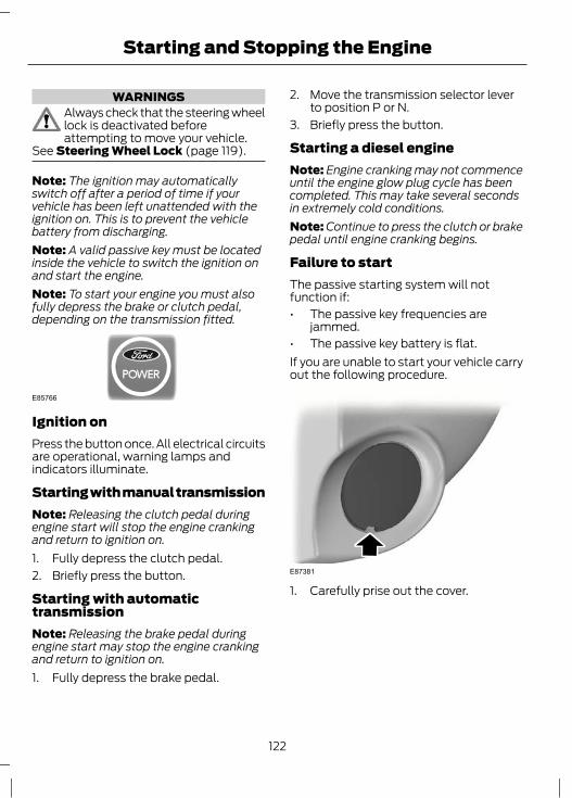
WARNINGSAlways check that the steering wheellock is deactivated beforeattempting to move your vehicle.
See Steering Wheel Lock (page 119).
Note: The ignition may automaticallyswitch off after a period of time if yourvehicle has been left unattended with theignition on. This is to prevent the vehiclebattery from discharging.Note: A valid passive key must be locatedinside the vehicle to switch the ignition onand start the engine.Note: To start your engine you must alsofully depress the brake or clutch pedal,depending on the transmission fitted.
E85766
Ignition onPress the button once. All electrical circuitsare operational, warning lamps andindicators illuminate.
Starting with manual transmissionNote: Releasing the clutch pedal duringengine start will stop the engine crankingand return to ignition on.1. Fully depress the clutch pedal.2. Briefly press the button.
Starting with automatictransmissionNote: Releasing the brake pedal duringengine start may stop the engine crankingand return to ignition on.1. Fully depress the brake pedal.
2. Move the transmission selector leverto position P or N.
3. Briefly press the button.
Starting a diesel engineNote: Engine cranking may not commenceuntil the engine glow plug cycle has beencompleted. This may take several secondsin extremely cold conditions.Note: Continue to press the clutch or brakepedal until engine cranking begins.
Failure to startThe passive starting system will notfunction if:• The passive key frequencies are
jammed.• The passive key battery is flat.If you are unable to start your vehicle carryout the following procedure.
E87381
1. Carefully prise out the cover.
122
Starting and Stopping the Engine

E85767
2. Insert the key into the key holder.
E85766
3. With the key in this position you canpress the button to switch the ignitionon and start your vehicle.
Stopping the engine with thevehicle stationaryNote: The ignition, all electrical circuits,warning lamps and indicators will beswitched off.
Manual transmissionBriefly press the button.
Automatic transmission1. Move the transmission selector lever
to position P.2. Briefly press the button.
Stopping the engine when thevehicle is moving
WARNINGSwitching off the engine when thevehicle is still moving will result in aloss of brake and steering assistance.
The steering will not be locked, but highereffort will be required. When the ignition isswitched off some electrical circuits,warning lamps and indicators may also beOFF.
Press and hold the button or press twicewithin two seconds.
DIESEL PARTICULATE FILTERThe DPF forms part of the emissionsreduction systems fitted to your vehicle. Itfilters harmful diesel particulates (soot)from the exhaust gas.
RegenerationWARNING
Do not park or idle your vehicle overdry leaves, dry grass or othercombustible materials. The DPF
regeneration process creates very highexhaust gas temperatures and the exhaustwill radiate a considerable amount of heatduring and after DPF regeneration, andafter you have switched the engine off.This is a potential fire hazard.
CAUTIONAvoid running out of fuel.
Note: During regeneration at low speed orengine idle, you may smell a hot metallicodour and could notice a clicking metallicsound. This is due to the high temperaturesreached during regeneration and is normal.
123
Starting and Stopping the Engine
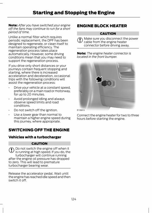
Note: After you have switched your engineoff the fans may continue to run for a shortperiod of time.Unlike a normal filter which requiresperiodic replacement, the DPF has beendesigned to regenerate, or clean itself tomaintain operating efficiency. Theregeneration process takes placeautomatically. However, some drivingconditions mean that you may need tosupport the regeneration process.If you drive only short distances or yourjourneys contain frequent stopping andstarting, where there is increasedacceleration and deceleration, occasionaltrips with the following conditions willassist the regeneration process:• Drive your vehicle at a constant speed,
preferably on a main road or motorway,for up to 20 minutes.
• Avoid prolonged idling and alwaysobserve speed limits and roadconditions.
• Do not switch off the ignition.• Use a lower gear than normal to
maintain a higher engine speed duringthis journey, where appropriate.
SWITCHING OFF THE ENGINEVehicles with a turbocharger
CAUTIONDo not switch the engine off when itis running at high speed. If you do, theturbocharger will continue running
after the engine oil pressure has droppedto zero. This will lead to prematureturbocharger bearing wear.
Release the accelerator pedal. Wait untilthe engine has reached idle speed and thenswitch it off.
ENGINE BLOCK HEATER
CAUTIONMake sure you disconnect the powercable from the engine heaterconnector before driving away.
Note: The engine heater connector islocated in the front bumper.
E135813
Connect the engine heater for two to threehours before starting the engine.
124
Starting and Stopping the Engine

PRINCIPLE OF OPERATION
CAUTIONFor vehicles with Start-stop thebattery requirement is different. Itmust be replaced by one of exactly
the same specification as the original.
The system reduces fuel consumption andCO2 emissions by shutting down theengine when the vehicle is idling, forexample at traffic lights. The engine willautomatically restart when the driverpresses the clutch pedal or when requiredby a vehicle system, for example torecharge the battery.To obtain maximum benefit from thesystem, move the gear lever to the neutralposition and release the clutch pedalduring any stop of longer than threeseconds.
USING START-STOP
WARNINGSThe engine may restartautomatically if required by thesystem. See Principle of Operation
(page 125).Switch the ignition off beforeopening the bonnet or carrying outany maintenance.Always switch the ignition off beforeleaving your vehicle, as the systemmay have shut down the engine but
the ignition will still be live.
Note: The system only operates when theengine is warm and the outside temperatureis between 0°C (32°F) and 30°C (86°F).
Note: If you stall the engine, and thendepress the clutch pedal within a couple ofseconds, the system will automaticallyrestart the engine.Note: The Start-stop indicator willilluminate green when the engine shutsdown. See Warning Lamps and Indicators(page 73).Note: The Start-stop indicator will flashamber, requiring you to select neutral ordepress the clutch pedal. In conjunction amessage will be shown in the display.Note: If the system detects a malfunction,it is deactivated. Have the system checkedby a properly trained technician.Note: If you have switched the system off,the switch will be illuminated.Note: The system is on by default. Toswitch the system off, press the switch inthe instrument panel. The system will onlybe de-activated for the current ignitioncycle. To turn it on, press the switch again.For item location. See At a Glance (page10).
To stop the engine1. Stop the vehicle.2. Move the gear lever to the neutral
position.3. Release the clutch pedal.4. Release the accelerator pedal.The system may not shut down the engineunder certain conditions, for example:• To maintain the interior climate.• Low battery voltage.• The outside temperature is too low or
too high.• The driver's door has been opened.
125
Start-Stop
• Low engine operating temperature.• Low brake system vacuum.• If a road speed of 5 km/h (3 mph) has
not been exceeded.• The driver's seat belt has not been
fastened.
To re-start the engineNote: The gear lever must be in the neutralposition.Depress the clutch pedal.The system may automatically restart theengine under certain conditions, forexample:• Low battery voltage.• To maintain the interior climate.
126
Start-Stop
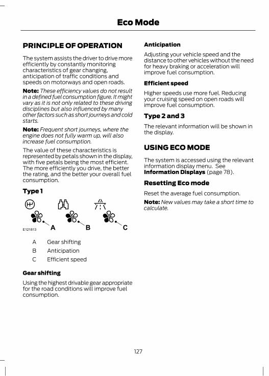
PRINCIPLE OF OPERATIONThe system assists the driver to drive moreefficiently by constantly monitoringcharacteristics of gear changing,anticipation of traffic conditions andspeeds on motorways and open roads.Note: These efficiency values do not resultin a defined fuel consumption figure. It mightvary as it is not only related to these drivingdisciplines but also influenced by manyother factors such as short journeys and coldstarts.Note: Frequent short journeys, where theengine does not fully warm up, will alsoincrease fuel consumption.The value of these characteristics isrepresented by petals shown in the display,with five petals being the most efficient.The more efficiently you drive, the betterthe rating, and the better your overall fuelconsumption.
Type 1
E121813 CBA
Gear shiftingAAnticipationBEfficient speedC
Gear shiftingUsing the highest drivable gear appropriatefor the road conditions will improve fuelconsumption.
AnticipationAdjusting your vehicle speed and thedistance to other vehicles without the needfor heavy braking or acceleration willimprove fuel consumption.
Efficient speedHigher speeds use more fuel. Reducingyour cruising speed on open roads willimprove fuel consumption.
Type 2 and 3The relevant information will be shown inthe display.
USING ECO MODEThe system is accessed using the relevantinformation display menu. SeeInformation Displays (page 78).
Resetting Eco modeReset the average fuel consumption.Note: New values may take a short time tocalculate.
127
Eco Mode

SAFETY PRECAUTIONS
WARNINGSStop refuelling after the fuel nozzlestops the second time. Additionalfuel will fill the expansion space in
the fuel tank which could lead to fueloverflowing. Fuel spillage could behazardous to other road users.
Do not use any kind of flames or heatnear the fuel system. The fuel systemis under pressure. There is a risk of
injury if the fuel system is leaking.
FUEL QUALITY - PETROL
CAUTIONDo not use leaded petrol or petrol withadditives containing other metalliccompounds (e.g. manganese-based).
They could damage the emission system.
Note: We recommend that you use onlyhigh quality fuel without additives or otherengine treatments.Use minimum 95 octane unleaded petrolthat meets the specification defined by EN228, or the equivalent nationalspecification.Your vehicle is suitable for use with ethanolblends up to 10% (E5 and E10).
FUEL QUALITY - E85
WARNINGSDo not modify the fuel systemconfiguration or the components inthe system.Do not replace the fuel system or thecomponents with parts not speciallydesigned to be used with E85.
CAUTIONSDo not use leaded petrol or petrol withadditives containing other metalliccompounds (e.g. manganese-based).
They could damage the emission system.Do not use methanol instead of E85.
Note: We recommend that you use onlyhigh quality fuel without additives or otherengine treatments.Note: When using E85, you may experiencea higher fuel consumption.Note: Your vehicle will operate well oncommercial quality 95 octane unleadedpetrol, but only high quality E85 offers thesame protection and performance.Use minimum 95 octane unleadedpetrol that meets the specification definedby EN 228, or equivalent. You can also usea mixture of unleaded petrol and E85.
Long-term storageDue to small amounts of corrosiveimpurities that may be found in the E85, itis recommended that you fill the tank withonly 95 octane unleaded petrol prior tolong-term storage of your vehicle.
FUEL QUALITY - DIESEL
WARNINGDo not mix diesel with oil, petrol orother liquids. This could cause achemical reaction.
CAUTIONSDo not add kerosene, paraffin orpetrol to diesel. This could causedamage to the fuel system.
128
Fuel and Refuelling
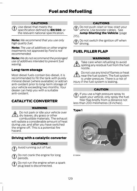
CAUTIONSUse diesel that meets thespecification defined by EN 590, orthe relevant national specification.
Note: We recommend that you use onlyhigh quality fuel.Note: The use of additives or other enginetreatments not approved by Ford is notrecommended.Note: We do not recommend the prolongeduse of additives intended to prevent fuelwaxing.
Long-term storageMost diesel fuels contain bio-diesel, it isrecommended to fill the tank with purelymineral diesel (where available) or add ananti-oxidant prior to long-term storage ofyour vehicle exceeding two months. Yourdealer can help you with a suitableanti-oxidant.
CATALYTIC CONVERTER
WARNINGDo not park or idle your vehicle overdry leaves, dry grass or othercombustible materials. The exhaust
will radiate a considerable amount of heatduring use, and after you have switchedthe engine off. This is a potential firehazard.
Driving with a catalytic converterCAUTIONS
Avoid running out of fuel.
Do not crank the engine for longperiods.Do not run the engine when a sparkplug lead is disconnected.
CAUTIONSDo not push-start or tow-start yourvehicle. Use booster cables. SeeJump-Starting the Vehicle (page
215).Do not switch the ignition off whendriving.
FUEL FILLER FLAP
WARNINGSTake care when refuelling to avoidspilling any residual fuel from the fuelnozzle.Do not use any kind of flames or heatnear the fuel system. The fuel systemis under pressure. There is a risk of
injury if the fuel system is leaking.
CAUTIONIf you use a high pressure spray towash your vehicle, only spray the fuelfiller flap briefly from a distance not
less than 200 millimetres (8 inches).
Type 1
E135934
129
Fuel and Refuelling

Type 2
E135935
1. Press the flap to open it. Open the flapfully until it engages.
E139202
A
Note: When you insert the fuel nozzle, aspring loaded inhibitor will open if thecorrect size nozzle is detected. This helpsto avoid filling up with the wrong fuel.2. Insert the fuel nozzle up to and
including the first notch on the nozzleA. Keep it resting on the cover of thefuel pipe opening.
WARNINGStop refuelling after the fuel nozzlestops the second time. Additionalfuel will fill the expansion space in
the fuel tank which could lead to fueloverflowing. Fuel spillage could behazardous to other road users.
E139203
A
B
Incorrect positionACorrect positionB
3. Do not lift the nozzle during refilling. Thiscan affect the flow of fuel and shut off ofthe fuel nozzle before the fuel tank is full.Type 1
E139204
130
Fuel and Refuelling

Type 2
E139205
4. Operate the nozzle within the areashown.
WARNINGSWe recommend that you remove thefuel nozzle slowly to allow anyresidual fuel to drain into the fuel
tank. Alternatively you can wait 10 secondsbefore removing the fuel nozzle.
Do not remove the nozzle from itsfully inserted position during theentire refuelling process.
E119081
5. Slightly raise the fuel nozzle to removeit.
Refuelling with a fuel canUse the funnel which is located in the glovebox.
REFUELLING
CAUTIONDo not attempt to start the engine ifyou have filled the fuel tank with theincorrect fuel. This could damage the
engine. Have the system checked by aproperly trained technician immediately.
REFUELLING - E85
CAUTIONDo not attempt to start the engine ifyou have filled the fuel tank with theincorrect fuel. This could damage the
engine. Have the system checked by aproperly trained technician immediately.
After refuelling, allow 5 minutes of normalengine operation above 48 km/h (30 mph)to reduce the risk of an increased enginerestart time.
FUEL CONSUMPTIONThe CO2 and fuel consumption figures arederived from laboratory tests according toEEC Directive 80/1268/EEC andsubsequent amendments and are carriedout by all vehicle manufacturers.They are intended as a comparisonbetween makes and models of vehicles.They are not intended to represent the realworld fuel consumption you may get fromyour vehicle. Real world fuel consumptionis governed by many factors including;driving style, high speed driving, stop/startdriving, air conditioning usage, theaccessories fitted and towing etc.Your Ford dealer can give you advice onimproving your fuel consumption.
131
Fuel and Refuelling

TECHNICAL SPECIFICATIONS
FocusFuel Consumption Figures
CO2 Emis-sionsCombinedExtra-UrbanUrban
Variantg/kml/100 km
(mpg)l/100 km
(mpg)l/100 km
(mpg)
1094.8 (58.9)4.1 (68.9)5.9 (47.9)1.0L EcoBoost(73kW/100PS), 5-door
1124.9 (57.6)4.2 (67.3)6 (47.1)1.0L EcoBoost(73kW/100PS), 4-door andestate
1145 (56.5)4.2 (67.3)6.3 (44.8)1.0L EcoBoost(92kW/125PS), 5-door
1175.1 (55.4)4.4 (64.2)6.4 (44.1)1.0L EcoBoost(92kW/125PS), 4-door andestate
1365.9 (47.9)4.7 (60.1)8 (35.3)1.6L Duratec-16V Ti-VCT, 5-door, vehicles with manualtransmission
1396 (47.1)4.8 (58.9)8.1 (34.9)1.6L Duratec-16V Ti-VCT, 4-door and estate, vehicleswith manual transmission
1496.4 (44.1)4.8 (58.9)9.3 (30.4)1.6L Duratec-16V Ti-VCT,vehicles with DPS6 auto-matic transmission
1446.2 (45.6)5 (56.5)8.3 (34)1.6L EcoBoost, vehicleswithout start-stop
1396 (47.1)5 (56.5)7.7 (36.7)1.6L EcoBoost, vehicles withstart-stop
1496.7 (42.2)5 (56.5)9.6 (29.4)2.0L Duratec-HE - MI4,vehicles with manual trans-mission
132
Fuel and Refuelling

CO2 Emis-sionsCombinedExtra-UrbanUrban
Variantg/kml/100 km
(mpg)l/100 km
(mpg)l/100 km
(mpg)
1566.4 (44.1)4.9 (57.6)9.1 (31)2.0L Duratec-HE - MI4,vehicles with automatictransmission
1697.2 (39.2)5.6 (50.4)9.9 (28.5)2.0L EcoBoost - MI4
1174.5 (62.8)3.7 (76.3)5.7 (49.6)1.6L Duratorq-TDCi, vehicleswithout start-stop
1094.2 (67.3)3.7 (76.3)5.1 (55.4)1.6L Duratorq-TDCi, vehicleswith start-stop
1295 (56.5)4.2 (67.3)6.3 (44.8)2.0L Duratorq-TDCi - DW,vehicles with manual trans-mission
1395.3 (53.3)4.4 (64.2)6.8 (41.5)2.0L Duratorq-TDCi - DW,vehicles with automatictransmission
133
Fuel and Refuelling
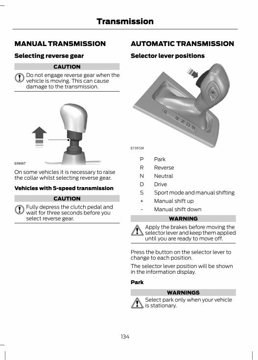
MANUAL TRANSMISSIONSelecting reverse gear
CAUTIONDo not engage reverse gear when thevehicle is moving. This can causedamage to the transmission.
E99067
On some vehicles it is necessary to raisethe collar whilst selecting reverse gear.
Vehicles with 5-speed transmission
CAUTIONFully depress the clutch pedal andwait for three seconds before youselect reverse gear.
AUTOMATIC TRANSMISSIONSelector lever positions
E133124
ParkPReverseRNeutralNDriveDSport mode and manual shiftingSManual shift up+Manual shift down-
WARNINGApply the brakes before moving theselector lever and keep them applieduntil you are ready to move off.
Press the button on the selector lever tochange to each position.The selector lever position will be shownin the information display.
Park
WARNINGSSelect park only when your vehicleis stationary.
134
Transmission

WARNINGSApply the parking brake andselect park before leaving yourvehicle. Make sure that the selector
lever is latched in position.
Note: An audible warning will sound if youopen the driver's door and you have notselected park.In this position, power is not transmittedto the drive wheels and the transmissionis locked. You can start the engine with theselector lever in this position.
Reverse
WARNINGSSelect reverse only when your vehicleis stationary and the engine is at idlespeed.Always come to a complete stopbefore shifting out of reverse.
Select reverse to allow the vehicle to movebackwards.
NeutralIn this position, power is not transmittedto the drive wheels but the transmission isnot locked. You can start the engine withthe selector lever in this position.
DriveNote: A shift will occur only when thevehicle speed and the engine speed areappropriate.Note: You may temporarily override thecurrent gear selected using the + and -buttons.Select drive to shift automatically throughthe forward gears.
The transmission will select theappropriate gear for optimum performancebased on ambient temperature, roadgradient, vehicle load and driver input.
Sport mode and manual shiftingSport ModeNote: In Sport mode the transmissionoperates as normal but gears are selectedmore quickly and at higher engine speeds.Note: In Sport mode S will be displayed onthe instrument panel.Activate Sport mode by moving theselector lever to position S. Sport modewill remain active until either you shiftmanually up or down the gears using + and-, or return the selector lever to position D.
Manual shifting
WARNINGDo not hold the buttons permanentlyin – or +.
CAUTIONThe transmission will automaticallydownshift when the engine speed istoo low.
Press the - button to shift down and pressthe + button to shift up.Gears may be skipped by pressing thebuttons repeatedly at short intervals.Manual mode also provides a kickdownfunction. See Kickdown.
Hints on driving with an automatictransmission
CAUTIONDo not idle the engine for long periodsof time in drive with the brakesapplied.
135
Transmission

Moving off1. Release the parking brake.2. Release the brake pedal and press the
accelerator pedal.
Stopping1. Release the accelerator pedal and
press the brake pedal.2. Apply the parking brake.3. Select neutral or park.
KickdownPress the accelerator pedal fully with theselector lever in the drive position to selectthe next lowest gear for optimumperformance. Release the acceleratorpedal when you no longer requirekickdown.
Emergency park position releaseleverUse the lever to move the selector leverfrom the park position in the event of anelectrical malfunction or if your vehicle hasa flat battery.
E13312813 2
1. Carefully remove the cover.2. Remove the retaining clip.3. Remove the centre console side panel.
E133129
4
Note: The lever is white.4. Apply the brake pedal. Using a suitable
tool press and hold the lever forwardwhile pulling the selector lever out ofthe park position and into the neutralposition.
136
Transmission

PRINCIPLE OF OPERATIONNote: Depending on applicable laws andregulations in the country for which yourvehicle was originally built, the brake lampsmay flash if you brake heavily.Note: Occasional brake noise is normal andoften does not indicate a concern. In normaloperation, the system may emit occasionalor intermittent squeal or groan noises whenthe brakes are applied. Such noises areusually caused by environmental conditionssuch as cold, heat, moisture, road dust, saltor mud.
Disc brakesWet brake discs result in reduced brakingefficiency. Dab the brake pedal whendriving from a car wash to remove the filmof water.
ABSWARNING
The ABS does not relieve you of yourresponsibility to drive with due careand attention.
The ABS helps you to maintain full steeringand directional stability when you brakeheavily in an emergency, by preventing theroad wheels from locking.
HINTS ON DRIVING WITHANTI-LOCK BRAKESNote: When the system is operating, thebrake pedal will pulse and may travelfurther. Maintain pressure on the brakepedal. You may also hear a noise from thesystem. This is normal.
The ABS will not eliminate the risks when:• you drive too close to the vehicle in
front of you• the vehicle is aquaplaning• you take corners too fast• the road surface is poor.
PARKING BRAKE
WARNINGVehicles with an automatictransmission should always be leftwith the selector lever in position P
(Park).
• Press the foot brake pedal firmly.• Pull the parking brake lever up smartly
to its fullest extent.• Do not press the release button while
pulling the lever up.• If your vehicle is parked on a hill and
facing uphill, select first gear or P(Park) and turn the steering wheelaway from the kerb.
• If your vehicle is parked on a hill andfacing downhill, select reverse gear orP (Park) and turn the steering wheeltowards the kerb.
To release the parking brake, press thebrake pedal firmly, pull the lever up slightly,depress the release button and push thelever down.
137
Brakes

PRINCIPLE OF OPERATIONElectronic stability programme(ESP)
WARNINGESP does not relieve you of yourresponsibility to drive with due careand attention.
E72903
A A
AB
B
B
B
without ESPAwith ESPB
The ESP supports stability when thevehicle starts to slide away from yourintended path. This is performed by brakingindividual wheels and reducing enginetorque as needed.The system also provides an enhancedtraction control function by reducingengine torque and may brake individualwheels if they spin when you accelerate.This improves your ability to pull away onslippery roads or loose surfaces, andimproves comfort by limiting wheel spin inhairpin bends.
Stability control (ESP) warning lampThe ESP warning lamp will flash when thesystem is operating. See Warning Lampsand Indicators (page 73).
Emergency brake assistWARNING
Emergency brake assist does notrelieve you of your responsibility todrive with due care and attention.
Emergency brake assist will detect whenyou brake heavily by measuring the rate atwhich you press the brake pedal. It willprovide maximum braking efficiency aslong as you press the pedal. Emergencybrake assist can reduce stopping distancesin critical situations.
Trailer stability controlWARNING
Trailer stability control does notrelieve you of your responsibility totow with due care and attention.
Trailer stability control is an enhancedfeature of ESP, and automatically detectswhen an attached trailer starts to sway.If this situation occurs, the system willautomatically brake individual wheels tostabilise the trailer and vehicle. In case avery severe sway is detected, the enginetorque will be reduced and the vehicle willbe slowed automatically.
USING STABILITY CONTROLNote: The system will be switched onautomatically every time you switch theignition on.To turn the system off and on. SeeInformation Displays (page 78).
138
Stability Control

USING STABILITY CONTROL -2.0L ECOBOOST SCTI (MI4)
WARNINGIf you switch stability control off,active city stop will also be switchedoff.
Note: The system will be switched onautomatically every time you switch theignition on.Note: You can also turn the system off andon using the information display. SeeGeneral Information (page 78).The switch is located in the instrumentpanel. See At a Glance (page 10).
Switching sport mode onNote: Stability control is only reduced andnot switched off completely.Press the switch. You will see a messagein conjunction with an illuminated icon inthe display. Press the switch again toreturn the system to normal mode.
Switching the system offPress and hold the switch forapproximately five seconds. You will seea message in conjunction with anilluminated icon in the display.
139
Stability Control

PRINCIPLE OF OPERATIONThe system makes it easier to pull awaywhen the vehicle is on a slope without theneed to use the parking brake.When the system is active, the vehicle willremain stationary on the slope for a shorttime after you release the brake pedal.During this time, you have time to moveyour foot from the brake to the acceleratorpedal and pull away. The brakes arereleased automatically once the enginehas developed sufficient drive to preventthe vehicle from rolling down the slope.This is an advantage when pulling awayon a slope, for example from a car parkramp, traffic lights or when reversing uphillinto a parking space.
WARNINGThe system does not replace theparking brake. When you leave thevehicle, always apply the parking
brake and select first or reverse gear.
USING HILL START ASSISTThe system is activated automaticallywhen you stop your vehicle on a slopegreater than 3%. The system operates withthe vehicle facing downhill if reverse gearis selected and with the vehicle facinguphill if any forward gear is selected.
Vehicles with manualtransmission onlyThe system can be switched on and offusing the information display. See GeneralInformation (page 78).
Activating the systemWARNINGS
You must remain in the vehicle onceyou have activated the system.
WARNINGSAt all times you are responsible forcontrolling the vehicle, supervisingthe system and intervening, if
required.If a malfunction is detected when thesystem is active, the system will bedeactivated and a message will be
shown in the display. See InformationMessages (page 86).
You can activate the system only if thefollowing conditions have been met:• The engine is running.• The system is switched on.• On vehicles with manual transmission,
the clutch pedal is pressed.• No failure mode is present.
To activate the system:1. Press the brake pedal to bring the
vehicle to a complete standstill. Keepthe brake pedal depressed.
2. If the sensors detect that the vehicle ison a slope the system will be activatedautomatically.
3. When you remove your foot from thebrake pedal, the vehicle will remain onthe slope without rolling away for ashort time. This hold time willautomatically be extended if you arein the process of driving off.
4. Drive off in the normal manner. Thebrakes will be released automatically.
Deactivating the systemTo deactivate the system, perform one ofthe following:
140
Hill Start Assist

• Wait for a short time until the systemdeactivates automatically.
• If a forward gear was selected whenthe system became active, selectreverse gear.
• If reverse gear was selected when thesystem became active, select aforward gear.
141
Hill Start Assist

PRINCIPLE OF OPERATION
WARNINGThe system does not relieve you ofyour responsibility to drive with duecare and attention.
CAUTIONSVehicles fitted with a trailer towmodule not approved by us may notcorrectly detect obstacles.The sensors may not detect objectsin heavy rain or other conditions thatcause disruptive reflections.The sensors may not detect objectswith surfaces that absorb ultrasonicwaves.The parking aid does not detectobstacles moving away from thevehicle. They will only be detected
shortly after they start to move towardsthe vehicle again.
If you use a high pressure spray towash your vehicle, only spray thesensors briefly from a distance not
less than 20 centimetres (8 inches).Parking aid sends tones via the audiosystem fitted and approved by us. Ifthis is not working the parking aid
system will not work.
Note: On vehicles fitted with a tow ballarm, the rear parking aid is deactivatedautomatically when any trailer lamps (orlighting boards) are connected to the 13-pinsocket via a trailer tow module we haveapproved.Note: Keep the sensors free from dirt, iceand snow. Do not clean with sharp objects.Note: The parking aid may emit false tonesif it detects a signal using the samefrequency as the sensors or if the vehicle isfully laden.
Note: The outer sensors may detect theside walls of a garage. If the distancebetween the outer sensor and the side wallremains constant for three seconds, thetone will switch off. As you continue, theinner sensors will detect rearward objects.
PARKING AID - VEHICLESWITH: REAR PARKING AID
WARNINGThe parking aid does not relieve youof your responsibility to drive withdue care and attention.
E77927
The parking aid is automatically activatedwhen you select reverse gear with theignition switched on.You will hear an intermittent tone at adistance of approximately 150 centimetres(59 inches) between the obstacle and rearbumper and approximately 50 centimetres(20 inches) to the side. Decreasing thedistance accelerates the intermittent tone.
142
Parking Aids

E130178
A
Distance Indicator.A
As the distance decreases the indicatormoves towards the vehicle.A continuous tone will start at a distanceof less than 30 centimetres (11 inches) tothe rear bumper.Note: On Vehicles with a tow bar fitted andapproved by us the continuous tone willstart at a distance of 45 centimetres (18inches) from the rear bumper.
E130179
A
Malfunction indicator.ANote: If a malfunction is indicated thesystem will be disabled. Have the systemchecked by a properly trained technician.
E130180
A trailer symbol indicates there is a trailerattached and the system is disabled.
PARKING AID - VEHICLESWITH: FRONT AND REARPARKING AID
WARNINGThe parking aid does not relieve youof your responsibility to drive withdue care and attention.
Switching the parking aid on andoffThe parking aid is per default off. To switchthe parking aid on, select reverse gear orpress the switch in the instrument panel.For item location: See At a Glance (page10).The light in the switch illuminates whenthe parking aid is activated.To turn it off, press the switch again.
143
Parking Aids

Manoeuvring with the parking aid
E130381
A B
D C
1
2
Reverse gear selected1Neutral or forward gear selected2Display and toneADisplay and toneBDisplay onlyCDisplay and toneD
You will hear an intermittent tone at adistance of approximately 150 centimetres(59 inches) between the obstacle and rearbumper, approximately 80 centimetres (31inches) between the obstacle and frontbumper and approximately 50 centimetres(20 inches) to the side. Decreasing thedistance accelerates the intermittent tone.A continuous tone will start at a distanceof less than 30 centimetres (11 inches) tothe front or rear bumper.Note: On vehicles with a tow bar fitted andapproved by us the continuous tone willstart at a distance of 45 centimetres (18inches) from the rear bumper.
You will hear an alternating tone from thefront and rear if obstacles are closer than30 centimetres (11 inches) to the front andrear bumpers.
E130382
A
Distance Indicator.A
As the distance decreases the indicatormoves towards the vehicle.
E130383
A
Malfuction indicator.ANote: If a malfunction is indicated thesystem will be disabled. Have the systemchecked by a properly trained technician.
144
Parking Aids

E130180
A trailer symbol indicates there is a trailerattached and the rear sensors are disabled.
145
Parking Aids

PRINCIPLE OF OPERATIONThe camera is a visual aid for use whenreversing.
WARNINGThe system does not relieve you ofyour responsibility to drive with duecare and attention.
CAUTIONSIf you use a high pressure spray towash your vehicle, only spray thecamera briefly from a distance not
less than 20 centimetres (8 inches).Do not apply pressure to the camera.
Note: Keep the camera free from dirt, iceand snow. Do not clean with sharp objects,degreaser, wax or organic products. Use onlya soft cloth.During operation, guide lines appear in thedisplay which represent your vehicle's pathand approximate distance from rearwardobjects.
REAR VIEW CAMERA
WARNINGSThe operation of the camera mayvary depending on the ambienttemperature, vehicle and road
conditions.The distances shown in the displaymay differ from the actual distance.Do not place objects in front of thecamera.
The camera is located on the luggagecompartment lid near the handle.
E99105
Activating the rear view cameraCAUTION
The camera may not detect objectsthat are close to the vehicle.
With the ignition and the audio unitswitched on:1. Press the parking aid switch in the
instrument panel. For item location:See At a Glance (page 10). Or,
2. Engage reverse gear.The image is displayed on the screen.The lamp in the switch illuminates whenthe system is activated.The camera may not operate correctly inthe following conditions:• Dark areas.• Intense light.• If the ambient temperature increases
or decreases rapidly.• If the camera is wet, for example in rain
or high humidity.• If the camera's view is obstructed, for
example by mud.
146
Rear view camera

Using the displayCAUTIONS
Obstacles above the camera positionwill not be shown. Inspect the areabehind your vehicle if necessary.Marks are for general guidance only,and are calculated for vehicles inmaximum load conditions on an even
road surface.
The lines show a projected vehicle path(based on the current steering wheelangle) and the distance from the exteriormirrors and rear bumper.
E99458
A
B
C
D E
A
B
C
D
Exterior mirror clearance - 0.1metre (4 inches)
A
Red - up to 0.3 (12 inches)BAmber - 0.3 - 0.6 metre (12 - 24inches)
C
147
Rear view camera
Green - 0.6 - 0.9 metre (24 - 35inches)
D
Amber - centre line of theprojected vehicle path
E
Note: The green line is extended from 0.9metre (35 inches) up to a distance of 3.2metres (126 inches).Note: When reversing with a trailer, the lineson the screen are not shown. The camerawill show the vehicle direction and not thetrailer.
Deactivating the rear view cameraNote: Disengage reverse gear. The displaywill stay on for a short period beforeswitching off.Note: The system will automatically switchoff once the vehicle speed has reachedapproximately 15 km/h (9 mph).Press the parking aid switch in theinstrument panel. For item location: SeeAt a Glance (page 10).
Vehicles with parking aidThe display will additionally show acoloured distance bar. This guide indicatesthe distance from the rear bumper to thedetected obstacle.These are colour coded as follows:• Green - 0.6 to 1.8 metres (24 - 71
inches).• Amber - 0.3 to 0.6 metre (12 - 24
inches).• Red - 0.3 metre (12 inches) or less.
148
Rear view camera
PRINCIPLE OF OPERATION
WARNINGSThe system does not relieve you ofyour responsibility to drive with duecare and attention.At all times you are responsible forcontrolling the vehicle, supervisingthe system and intervening if
required.You must observe that the selectedspace remains clear of obstructionsat all times in the manoeuver.Vehicles with overhanging loads,street furniture and other items maynot be detected by the system. You
must make sure that the selected spaceis suitable for parking.
Do not use the system if a trailer isattached to the vehicle.Do not use the system if a bike rackis attached to the back of the vehicle.Do not use the system if anoverhanging item is attached to theroof.If the manoeuvre is interruptedbefore completion, the system willbe disabled. The steering wheel
position will not indicate the true positionof the steering and you will have to takecontrol of the vehicle.
Make sure that loose clothing, yourhands or your arms do not get caughtin the rotating steering wheel.
The system will detect a suitable parallelparking space and steer the vehicle intothe space. The system controls thesteering while the driver controls theaccelerator, transmission and brakes. Themanoeuvre can be stopped at any time byholding the steering wheel or pressing theactive park assist switch. See At a Glance(page 10).The system will visually and audiblyinstruct the driver throughout theprocedure to safely park the vehicle.
USING ACTIVE PARK ASSIST
CAUTIONSThe sensors may not detect objectsin heavy rain or other conditions thatcause disruptive reflections.The sensors may not detect objectswith surfaces that absorb ultrasonicwaves.The sensors may not detect the kerb.
Note: If the traction control system isdisabled active park assist will not beavailable. See General Information (page78).The system will not align the vehiclecorrectly if:• a spare tyre, or a tyre worn significantly
more than the other tyres is used• the factory installed tyre size is not
used on the vehicle• the tyres skid• you allow the vehicle to roll• the weather conditions are poor (heavy
rain, snow, fog, etc).
149
Active Park Assist

Move forwards at a maximum speed of 30km/h (18 mph). Press the active park assistswitch. See At a Glance (page 10). Usethe direction indicator lever to selectsearching either to the left-hand side orright-hand side of the vehicle.
Note: If no selection is made via thedirection indicator lever the system willdefault to the passenger side of the vehicle.
A
E130107
Note: To disable the chimes: SeePersonalised Settings (page 85).The information and entertainment displaywill inform you and a chime will be heardwhen a suitable space is found. To parkthe vehicle, follow the instructions on theinformation and entertainment display.
Note: The arrow symbols or graphics in thedisplay indicate on which side of the vehiclethe system will park. The display will alsoadvise you when to select reverse gear.Slow down and stop at approximatelyposition A, then follow the systeminstructions.
E130108
WARNINGIf a speed of 10 km/h (6 mph) isexceeded the system will be disabledand you will need to take full control
of the vehicle.
Move the vehicle backwards cautiouslyusing the accelerator and brake pedals tocontrol the vehicle. Parking aid warningtones will sound. Stop the vehicle whenyou hear a continuous tone.
150
Active Park Assist
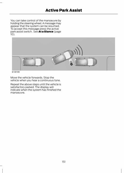
You can take control of the manoeuvre byholding the steering wheel. A message mayappear that the system can be resumed.To accept this message press the activepark assist switch. See At a Glance (page10).
E130109
Move the vehicle forwards. Stop thevehicle when you hear a continuous tone.Repeat the above steps until the vehicle issatisfactory parked. The display willindicate when the system has finished themanoeuvre.
151
Active Park Assist

PRINCIPLE OF OPERATION
WARNINGThe system does not relieve you ofyour responsibility to drive with duecare and attention.
Cruise control allows you to control yourspeed using the switches on the steeringwheel. You can use cruise control whenyou exceed approximately 30 km/h (20mph).
USING CRUISE CONTROL
WARNINGDo not use cruise control in heavytraffic, on twisty roads or when theroad surface is slippery.
Switching cruise control on
E130072
Note: The system is ready for you to set aspeed.
Setting a speedPress the SET+ switch or the SET- switchto store and maintain your current speed.The cruise control indicator will illuminate.See Warning Lamps and Indicators(page 73).
Changing the set speedWARNING
When you are going downhill, yourspeed may increase above the setspeed. The system will not apply the
brakes. Change down a gear and press theSET- switch to assist the system inmaintaining the set speed.
Note: If you accelerate by pressing theaccelerator pedal, the set speed will notchange. When you release the acceleratorpedal, you will return to the speed that youpreviously set.
E130073
A
B
AccelerateADecelerateB
Cancelling the set speedPress the brake pedal or pull the CANswitch.
152
Cruise Control

Note: The system will no longer controlyour speed. The cruise control indicator willnot illuminate but the system will retain thespeed that you previously set.
Resuming the set speedPull the RES switch.The cruise control indicator will illuminateand the system will attempt to resume thespeed that you previously set.
Switching cruise control off
E130072
The system will not retain the speed thatyou previously set. The cruise controlindicator will not illuminate.
153
Cruise Control

PRINCIPLE OF OPERATION
WARNINGSThe system is not a collision warningor avoidance system. The separateforward alert function provides a
collision warning and mitigation feature.See Forward alert function (page 158).You must intervene if the system does notdetect a vehicle in front.
When driving you are responsible formaintaining the correct distance andspeed, even when adaptive cruise
control is used. You must always payattention to the traffic conditions andintervene when adaptive cruise control isnot maintaining a suitable speed orsuitable distance.
The system does not relieve you ofyour responsibility to drive with duecare and attention.The system does not brake for slowor stationary vehicles, pedestrians,objects in the road, oncoming and
crossing vehicles.
CAUTIONSOnly use adaptive cruise control whenconditions are favourable, for exampleon motorways and main roads with
steady free flowing traffic.Do not use in poor visibility,specifically fog, heavy rain, spray orsnow.Do not use on icy or slippery roads.
Do not use the system when enteringor leaving a motorway.The radar sensor has a limited field ofvision. In some situations it maydetect a vehicle other than the one
expected or not detect any vehicle at all.
Note: When adaptive cruise control isactivated, you may hear some unusualsounds during automatic braking. This isnormal and caused by the automaticbraking system.Note: Keep the front of the vehicle freefrom dirt, metal badges or objects, includingvehicle front protectors and additional lightswhich may prevent the sensor fromoperating.The system is designed to help youmaintain a gap from the vehicle ahead ora set road speed if there is no slowervehicle ahead. The system is intended toprovide enhanced operation of the vehiclewhen following other vehicles which are inthe same lane and travelling in the samedirection.The system is based on the use of a radarsensor which projects a beam directlyforward of the vehicle. This beam willdetect any vehicle ahead within thesystem's range.The radar sensor is mounted behind thefront grille.
154
Adaptive cruise control (ACC)
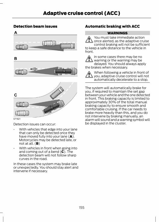
Detection beam issues
E71621
Detection issues can occur:• With vehicles that edge into your lane
that can only be detected once theyhave moved fully into your lane (A).Motorcycles may be detected late, ornot at all. (B)
• With vehicles in front when going intoand coming out of a bend (C). Thedetection beam will not follow sharpcurves in the road.
In these cases the system may brake lateor unexpectedly. You should stay alert andintervene if necessary.
Automatic braking with ACCWARNINGS
You must take immediate actiononce alerted, as the adaptive cruisecontrol braking will not be sufficient
to keep a safe distance to the vehicle infront.
In some cases there may be nowarning or the warning may bedelayed. You should always apply
the brakes when necessary.When following a vehicle in front ofyou, adaptive cruise control will notautomatically decelerate to a stop.
The system will automatically brake foryou, if required to maintain the set gapbetween your vehicle and the one detectedin front. This braking capacity is limited toapproximately 30% of the total manualbraking capacity to ensure smooth andcomfortable cruising. If the car needs tobrake more heavily than this, and you donot intervene by braking manually, analarm will sound and a warning symbol willbe displayed in the cluster.
155
Adaptive cruise control (ACC)

USING ADAPTIVE CRUISECONTROLThe system is operated by adjustmentcontrols mounted on the steering wheel.
E133195
A
B
F
CD
E
Set speed increaseASet speed decreaseBACC on/offCACC gap increaseDACC gap decreaseEACC cancel/resumeF
Switching the system onPress switch C. The system is set tostandby mode.
Setting a speedNote: The system must be in standbymode.Press switch A or switch B to select yourdesired cruise speed. The speed isdisplayed in the information display andstored as the set speed.
Changing the set speedNote: Vehicle speed may be increased anddecreased at intervals of 5 km/h or 5 mph.Note: If the system does not react to thesechanges the reason may be that the gapinterval to the vehicle in front prevents anincrease in speed.Press switch A to increase or switch B todecrease the set speed until the desiredset speed is shown in the informationdisplay. The vehicle speed will graduallychange to the selected speed.
Setting the vehicle gapCAUTION
Use the appropriate gap setting inaccordance with local trafficregulations.
Note: The gap setting is time dependentand therefore the distance willautomatically adjust with your speed. Forexample on a gap setting of four bars, thetime gap is 1.8 seconds. This will mean thatat a speed of 100 km/h (62 mph), thedistance to the vehicle in front will bemaintained at 50 metres (164 feet).Note: If the accelerator is depressed for ashort period, for example when overtaking,the system is temporarily deactivated andthen reactivated when the accelerator pedalis released. A message is displayed in theinformation display.Note: The gap setting will remainunchanged during ignition cycles.
E82311
156
Adaptive cruise control (ACC)

The distance between you and the vehicledetected in front is maintained by avariable setting. There are five steps whichare represented by horizontal barsdisplayed in the information display. Onebar indicates the smallest gap and fivebars indicates the largest gap. These barsare shown empty when in standby modeand filled when in active mode.If no vehicle is detected in front, then onlyyour vehicle is displayed in the informationdisplay below the bars. The system willmaintain the set speed when conditionspermit. The set gap is maintained anddisplayed.If a vehicle is detected by the sensor, thedisplay will show another vehicle abovethe horizontal bars:
E82312
This is a follow mode, and the system willaccelerate or decelerate as necessary tomaintain the set gap.Pull switch E to decrease the gap or switchD to increase the gap. The gap selectedwill be represented by the number of barsin the display.Note: The recommended gap setting is fouror five bars.
Temporarily deactivating thesystemNote: The system is cancelled when thegear lever is moved to a neutral position orif the accelerator pedal or clutch isdepressed for a long period of time.
Press the brake pedal or pull switch F tocancel the system. The system will returnto standby mode allowing you full manualcontrol of the vehicle. The set speed andgap setting are retained in the memory.Pull switch F again to resume. The systemwill resume with the previously set speedand vehicle gap setting if conditions permit.
Switching the system offPress switch C to turn the system off.Note: When deactivating the system bypressing switch C, the stored speed is notretained.
Automatic deactivationNote: If the engine speed drops too low, amessage is displayed in the informationdisplay instructing you to change down agear (manual transmission only). If you donot follow this recommendation then thesystem will go into automatic deactivationmode.Note: The system will not operate iftraction control has been switched off.The system is dependent on various othersafety systems, for example ABS and ESP.If any of these systems are malfunctioningor reacting to an emergency, the system isautomatically deactivated.In the event of automatic deactivation asignal will sound and the message isdisplayed in the information display. SeeInformation Messages (page 86). Youmust then intervene and adapt your drivingand speed to vehicles in front.An automatic deactivation can be due tothe:• vehicle speed falling below 30 km/h
(20 mph)• wheels losing traction
157
Adaptive cruise control (ACC)

• brake temperature being too high, forexample when driving on mountainousor hilly roads
• engine speed being too low• radar sensor being covered• parking brake being applied.
FORWARD ALERT FUNCTION
WARNINGSNever wait for a collision warning.When driving you are responsible formaintaining the correct distance and
speed, even when the system is used.The system will only react to vehiclesin front travelling in the samedirection and will not react to slow
or stationary vehicles.Never drive in a manner to provokethe system. The system is designedto assist in emergencies only.
CAUTIONSWarnings may be triggered late, beabsent or triggered unnecessarily dueto detection beam issues. See
Principle of Operation (page 154).The system uses the same radarsensors as adaptive cruise control andtherefore has the same limitations.
See Principle of Operation (page 154).
Note: The brake support system onlyreduces the collision speed if you brakeimmediately once alerted.Note: If the brake pedal is depressedsufficiently quickly then braking isimplemented with full brake function, evenif the force on the pedal is light.Note: Brake support prepares the brakesystem for rapid braking and the brakes areapplied gently, which may be noticed as aslight jerk.
Note: The collision alerts will only occur ifthe system is switched on, however thebrake support is always on and cannot beturned off.Note: The system may be used with orwithout the Adaptive cruise control systembeing activated.The system assists you by warning of therisk of a collision with a vehicle in front.The system alerts you by warning chimesand a visual warning in the informationdisplay. See Information Messages(page 86).Brake support is activated to enable fullbraking effectiveness, and reduce theseverity of a collision with the vehicle infront.
Switching the system on and offNote: When the system is switched off, awarning indicator will remain illuminated inthe information display. See WarningLamps and Indicators (page 73).Note: The system status and settings willremain unchanged during ignition cycles.The system can be switched on and offusing the information display. See GeneralInformation (page 78).
Adjusting the warning sensitivityYou may adjust the system warningsensitivity using the buttons on the steeringwheel. See General Information (page78). This controls how early the visual andaudible warning is activated.
158
Adaptive cruise control (ACC)

PRINCIPLE OF OPERATION
WARNINGWhen you are going downhill, yourspeed may increase above the setspeed. The system will not apply the
brakes but a warning will be given.
The system allows you to set a speed, towhich the vehicle then becomes limited.The set speed will become the effectivemaximum speed of the vehicle, but withthe option to temporarily exceed this limitif required.
USING THE SPEED LIMITERNote: The set speed limit can beintentionally exceeded for a short period ifrequired, for example when overtaking.The system is operated by adjustmentcontrols mounted on the steering wheel.
E133198
A
B
C
D
Set speed increaseASpeed limiter on/offBSet speed decreaseCSpeed limiter cancel/resumeD
Switching the system on and offPress switch B. The information displaywill prompt for a speed to be set.
Setting the speed limitUse the cruise control switches to alter themaximum speed setting.Press switch A or switch C to select yourdesired speed limit. The speed is displayedin the information display and stored asthe set speed.Pull switch D to cancel the limiter andplace it in standby mode. The informationdisplay will confirm deactivation byshowing the set speed crossed out.Pull switch D again to resume the limiter.The information display will confirm thesystem is active by showing the set speedagain.
Intentionally exceeding the setspeed limitDepress the accelerator fully to temporarilydeactivate the system. The system willreactivate once the vehicle speed dropsbelow the set speed.
System warningsIf the set limit is accidentally exceeded, forexample driving downhill, the informationdisplay will show the set speed flashingtogether with an audible warning chime.If the set limit is intentionally exceeded theinformation display will show the set speedcrossed out.
159
Speed Limiter

PRINCIPLE OF OPERATION
WARNINGSThe system does not relieve you ofyour responsibility to drive with duecare and attention.At all times you are responsible forcontrolling the vehicle, supervisingthe system and intervening if
required.If the sensor becomes blocked thesystem may not function.Take regular rest breaks as requiredand do not wait for the system towarn you if you feel tired.Take rest breaks only where it is safeto do so.Certain driving styles and behaviourmay result in the system issuing awarning even if you are not feeling
tired.
CAUTIONSIn cold and severe weather conditionsthe system may not function. Rain,snow, spray and large contrasts in
lighting can all influence the sensor.The system will not operate if thesensor cannot track the road lanemarkings.The system may not operate in areasduring roadworks construction.The system may not operate on roadswith sharp bends or narrow lanes.Do not carry out windscreen repairs inthe immediate area surrounding thesensor.If your vehicle is fitted with asuspension kit not approved by us, thesystem may not function correctly.
Note: Keep the windscreen free fromobstructions such as bird droppings, insectsand snow or ice.Note: The system is intended as a driver aidwhen driving on fast main roads andmotorways.Note: The system calculates an alertnesslevel at vehicle speeds above approximately65 km/h (40 mph).The system automatically monitors yourdriving behaviour using various inputsincluding the front camera sensor.If the system detects that you arebecoming drowsy or there is a deteriorationin your driving, the system will alert you.
USING DRIVER ALERTSwitching the system on and offNote: The system status will remainunchanged during ignition cycles.Activate the system using the informationdisplay. See Information Displays (page78).Once activated the system will calculateyour alertness level based upon yourdriving behaviour in relation to the lanemarkings, and other factors.
System warningsNote: The system will not issue warningsbelow approximately 65 km/h (40 mph).The warning system is in two stages. Atfirst the system issues a temporary warningthat a rest should be taken. This messagewill only appear for a short time. If a rest isnot then taken a further warning may beissued which will remain in the informationdisplay until cancelled. See InformationMessages (page 86).Press OK on the steering wheel control toremove the warning.
160
Driver Alert

System displayWhen active the system will runautomatically in the background and onlyissue warnings if required. You can viewthe status at any time using theinformation display. See GeneralInformation (page 78).The alertness level is shown by six stepsas a coloured bar.
E131358
Alertness level is fine, no rest required.
E131359
Alertness level is critical, indicating that arest should be taken as soon as safelypossible.The status bar will travel from left to rightas the calculated alertness leveldecreases. As the rest icon is approachedthe colour turns from green to yellow andthen finally red when a rest break must betaken.• Green - No rest required.• Yellow - First (temporary) warning.• Red - Second warning.Note: The alertness level will be shown ingrey if the camera sensor cannot track theroad lane markings or if the vehicle speeddrops below approximately 65 km/h (40mph).
Resetting the systemYou can reset the system by either:• Switching the ignition off and on.• Stopping the vehicle and then opening
and closing the driver's door.
161
Driver Alert

PRINCIPLE OF OPERATION
WARNINGSThe system does not relieve you ofyour responsibility to drive with duecare and attention.At all times you are responsible forcontrolling the vehicle, supervisingthe system and intervening if
required.If the sensor becomes blocked thesystem may not function.Lane markings may not always beproperly tracked by the sensor. Otherstructures or objects may sometimes
be incorrectly detected as a lane marking,resulting in a false or missed warning.
CAUTIONSIn cold and severe weather conditionsthe system may not function. Rain,snow, spray and large contrasts in
lighting can all influence the sensor.The system will not operate if thesensor cannot track the road lanemarkings.The system may not operate in areasduring roadworks construction.The system may not operate on roadswith sharp bends or narrow lanes.Do not carry out windscreen repairs inthe immediate area surrounding thesensor.If your vehicle is fitted with asuspension kit not approved by us, thesystem may not function correctly.
Note: Keep the windscreen free fromobstructions such as bird droppings, insectsand snow or ice.
Note: The system is intended as a driver aidwhen driving on fast main roads andmotorways.Note: The system may not operate duringhard braking or acceleration and, when youare intentionally steering the vehicle.Note: The system will operate with aminimum of one tracked lane marking.Note: The system will only operate abovevehicle speeds of approximately 65 km/h(40 mph).A sensor is mounted behind the interiorrear view mirror. It continuously monitorsconditions to alert you of unintentionallane drifting at high speeds.The system will automatically detect andtrack the lane markings on the road. If itdetects that the vehicle is unintentionallydrifting towards the lane boundaries thena visual warning will be displayed in theinformation display. There is also a warninggiven in the form of a vibration felt throughthe steering wheel.
USING LANE DEPARTUREWARNINGSwitching the system on and offNote: When the system is switched off, awarning indicator will remain illuminated inthe information display. See WarningLamps and Indicators (page 73).Note: The system status and settings willremain unchanged during ignition cycles.
E132099
162
Lane Departure Warning

Activate and deactivate the system usingthe button on the indicator stalk.Press the button to turn the system off.Press the button twice to turn the systemon.
Setting the steering wheelvibration levelThe system has three intensity levels whichcan be set using the information display.See General Information (page 78).
Setting the system sensitivityYou can adjust how quickly the systemwarns you of a dangerous situation. Thesystem has two sensitivity levels which canbe set using the information display. SeeGeneral Information (page 78).
System warnings
E132651
A column of lane markings is displayedeither side of the vehicle graphic.
The lane markings are colour coded asfollows:• Green - The system is ready to warn
you of any unintentional lanedeparture.
• Red - The vehicle is approaching or istoo close to the detected laneboundary. Take immediate safe actionto reposition the vehicle.
• Grey - The relevant lane boundary willbe suppressed.
Instances where a lane boundary may besuppressed:• Lane markings on the road may not be
detected by the sensor.• The direction indicator for that side of
the vehicle is on.• During hard acceleration and braking,
or if direct steering is applied.• Vehicle speed is outside the operating
limits• If there is an ABS or Stability Control
(ESP) intervention.• Narrow lane width.If the lane markings turn red or a vibrationis felt through the steering wheel you musttake immediate and safe action to alignthe vehicle and correct any unintendedlane drift.
163
Lane Departure Warning

PRINCIPLE OF OPERATION
WARNINGSThe system does not relieve you ofyour responsibility to drive with duecare and attention.At all times you are responsible forcontrolling the vehicle, supervisingthe system and intervening if
required.If the sensor becomes blocked thesystem may not function.Lane markings may not always beproperly tracked by the sensor. Otherstructures or objects may sometimes
be incorrectly detected as a lane marking,resulting in a false or missed warning inconjunction with a false or missed steeringintervention.
Always have your hands on thesteering wheel in case you need tooverrule the system.
CAUTIONSIn cold and severe weather conditionsthe system may not function. Rain,snow, spray and large contrasts in
lighting can all influence the sensor.The system will not operate if thesensor cannot track the road lanemarkings.The system may not operate in areasduring roadworks construction.The system may not operate on roadswith sharp bends or narrow lanes.Do not carry out windscreen repairs inthe immediate area surrounding thesensor.If your vehicle is fitted with asuspension kit not approved by us, thesystem may not function correctly.
Note: Keep the windscreen free fromobstructions such as bird droppings, insectsand snow or ice.Note: The system is intended as a driver aidwhen driving on fast main roads andmotorways.Note: The system may not operate duringhard braking or acceleration and when youare intentionally steering the vehicle.Note: The system will operate with aminimum of one tracked lane marking.Note: The system will only operatebetween vehicle speeds of approximately65 km/h (40 mph) and 180 km/h (112 mph).Note: If the system does not detect anactive steering input by the driver it will betemporarily deactivated until you resumecontrol. The system alerts you with awarning chime and a message in the display.A sensor is mounted behind the interiorrear view mirror. It continuously monitorsconditions to alert you of unintentionallane drifting at high speeds.The system will automatically detect andtrack the lane markings on the road. If itdetects that the vehicle is unintentionallydrifting towards the lane boundaries thena visual warning will be displayed in theinformation display. The system will alsoautomatically apply a steering torque tocorrect the vehicle path. If the system isunable to correct the vehicle path a lanedeparture warning will be given. See Usinglane departure warning (page 162).
USING THE LANE KEEPING AIDSwitching the system on and offNote: The system is per default off.Note: When the system has been switchedon, lane departure warning is per default on.
164
Lane Keeping Aid
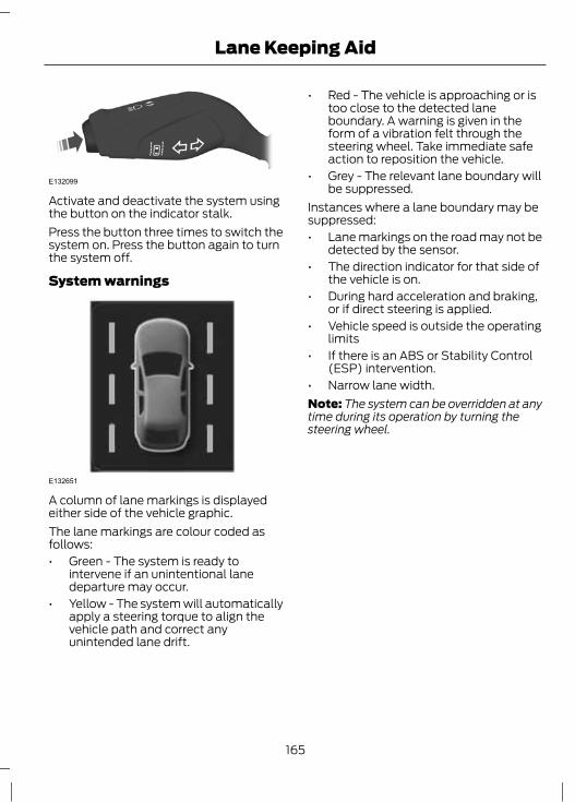
E132099
Activate and deactivate the system usingthe button on the indicator stalk.Press the button three times to switch thesystem on. Press the button again to turnthe system off.
System warnings
E132651
A column of lane markings is displayedeither side of the vehicle graphic.The lane markings are colour coded asfollows:• Green - The system is ready to
intervene if an unintentional lanedeparture may occur.
• Yellow - The system will automaticallyapply a steering torque to align thevehicle path and correct anyunintended lane drift.
• Red - The vehicle is approaching or istoo close to the detected laneboundary. A warning is given in theform of a vibration felt through thesteering wheel. Take immediate safeaction to reposition the vehicle.
• Grey - The relevant lane boundary willbe suppressed.
Instances where a lane boundary may besuppressed:• Lane markings on the road may not be
detected by the sensor.• The direction indicator for that side of
the vehicle is on.• During hard acceleration and braking,
or if direct steering is applied.• Vehicle speed is outside the operating
limits• If there is an ABS or Stability Control
(ESP) intervention.• Narrow lane width.Note: The system can be overridden at anytime during its operation by turning thesteering wheel.
165
Lane Keeping Aid

PRINCIPLE OF OPERATION
WARNINGSThe system does not relieve you ofyour responsibility to drive with duecare and attention.At all times you are responsible forcontrolling the vehicle, supervisingthe system and intervening if
required.If the sensor becomes blocked thesystem may not function.
CAUTIONSIn cold and severe weather conditionsthe system may not function. Rain,snow, spray and large contrasts in
lighting can all influence the sensor.Do not carry out windscreen repairs inthe immediate area surrounding thesensor.If your vehicle is fitted with asuspension kit not approved by us, thesystem may not function correctly.Always fit Ford Original Parts whenreplacing headlamp bulbs. Otherbulbs may reduce system
performance.
Note: Keep the windscreen free fromobstructions such as bird droppings, insectsand snow or ice.Note: The system may not detect all trafficsigns.Note: The system is designed to read signsmeeting the Vienna convention.A sensor is mounted behind the interiorrear view mirror. It continuously monitorsroad signs to alert you of the current legalspeed limit and overtaking regulations.
The system will automatically detectrecognizable traffic signs, for examplespeed limit signs, no overtaking signs andspeed limit cancellation signs.
USING TRAFFIC SIGNRECOGNITIONSwitching the system on and offNote: The system status and settings willremain unchanged during ignition cycles.The system can be switched on and offusing the information display. See GeneralInformation (page 78).
Setting the system speed warningThe system has a number of speedwarning levels which can be set using theinformation display. See GeneralInformation (page 78).
System display
E132994
The system can display two traffic signsin parallel.You can view the status at any time usingthe information display.The system display is in four stages asfollows:1. All new recognisable traffic signs will
appear brighter than the other warningsigns in the display.
2. After a predetermined time they willbe shown normally.
166
Traffic Sign Recognition

3. After a predetermined distance theywill be shown greyed out.
4. After another predetermined distancethey will be deleted.
If a supplementary traffic sign is detected,for example a reduced speed limit in wetroad conditions sign, it will not be shownbut will appear as an empty boxunderneath the respective sign.
167
Traffic Sign Recognition
PRINCIPLE OF OPERATION
WARNINGSThe system does not relieve you ofyour responsibility to drive with duecare and attention.At all times you are responsible forcontrolling the vehicle, supervisingthe system and intervening if
required.Never look directly into the sensorwith any type of object, there is a riskof eye injury.If the sensor becomes blocked thesystem may not function.To achieve full system performance,the brake system needs to bebedded in. See Running-In (page
182).The system performance may varydepending on the vehicle and roadconditions.The system will not react to vehiclesdriving in a different direction.The system will not react to bicycles,motorcycles, people or animals.When the ignition is on the sensorwill constantly transmit a laserbeam.The system will not operate duringharsh acceleration and steering.In cold and severe weatherconditions the system may notfunction. Rain, snow, spray and ice
can all influence the sensor.Do not carry out windscreen repairsin the immediate area surroundingthe sensor.If your vehicle is fitted with awindscreen not approved by us, thesystem may not function correctly.
WARNINGSIf the engine stops after the systemhas been activated, the hazardwarning flashers will be activated.The system may not function whendriving around sharp curves.
Note: Keep the windscreen free fromobstructions such as bird droppings, insectsand snow or ice.Note: Keep the bonnet free of ice and snow,otherwise the system may not functioncorrectly.A sensor is mounted behind the interiorrear view mirror. It continuously monitorsconditions to decide when to intervene.The system is designed to help you reducelow speed collisions into the rear ofanother vehicle. It will also help you reducethe impact damage or potentially avoidthe collision completely.The system operates at speeds belowapproximately 30 km/h (19 mph) byapplying the brakes when the sensordetects that a collision is likely.You must depress the brake pedal toobtain full braking force.When the system is braking or hasautomatically applied the brakes, amessage will be shown in the display.For laser sensor information and data: SeeType approvals (page 299).
USING ACTIVE CITY STOP
WARNINGNever look directly into the sensorwith any type of object, there is a riskof eye injury.
168
Active City Stop

Switching the system on and offNote: The system is per default on.Note: In certain situations, it may beadvisable to disable the system, for exampledriving off road when objects may cover thewindscreen.Activate and deactivate the system usingthe information display. See GeneralInformation (page 78).
USING ACTIVE CITY STOP -2.0L ECOBOOST SCTI (MI4)
WARNINGSNever look directly into the sensorwith any type of object, there is a riskof eye injury.If you switch stability control off,active city stop will also be switchedoff. A message will be shown in the
display.
Switching the system on and offNote: The system is per default on.Note: In certain situations, it may beadvisable to disable the system, for exampledriving off road when objects may cover thewindscreen.Activate and deactivate the system usingthe information display. See GeneralInformation (page 78).
169
Active City Stop
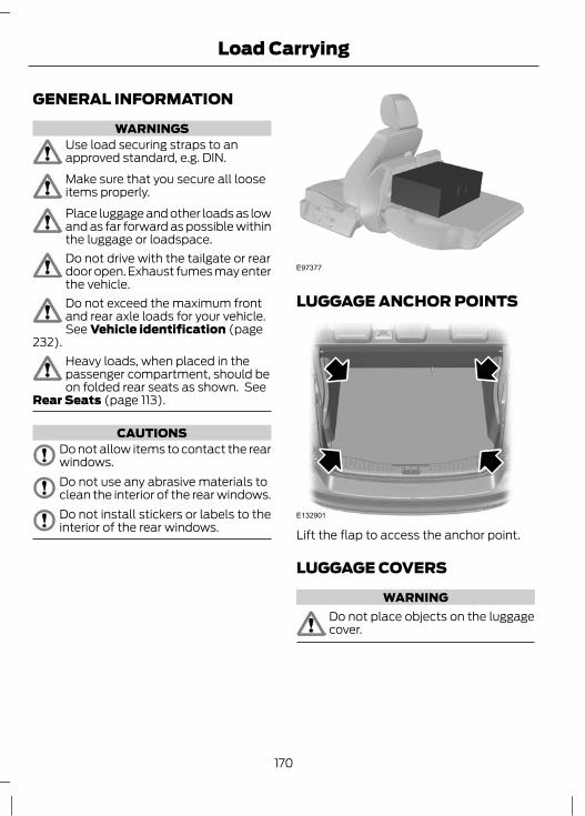
GENERAL INFORMATION
WARNINGSUse load securing straps to anapproved standard, e.g. DIN.Make sure that you secure all looseitems properly.Place luggage and other loads as lowand as far forward as possible withinthe luggage or loadspace.Do not drive with the tailgate or reardoor open. Exhaust fumes may enterthe vehicle.Do not exceed the maximum frontand rear axle loads for your vehicle.See Vehicle identification (page
232).Heavy loads, when placed in thepassenger compartment, should beon folded rear seats as shown. See
Rear Seats (page 113).
CAUTIONSDo not allow items to contact the rearwindows.Do not use any abrasive materials toclean the interior of the rear windows.Do not install stickers or labels to theinterior of the rear windows.
E97377
LUGGAGE ANCHOR POINTS
E132901
Lift the flap to access the anchor point.
LUGGAGE COVERS
WARNINGDo not place objects on the luggagecover.
170
Load Carrying

E72969
Pull out the cover and secure it in theretaining points.Release it from the retaining points and letit roll back into the case. Clip the retaininghook onto the case.
E72970
To remove or install the cover, push eitherend of the case inwards.
CARGO NETSLuggage retention net
WARNINGOn Estate vehicles, luggage retentionnet anchor points are not fittedbehind the first row seats, but are
fitted behind the second row seats.
To install the cargo retention net cassette:Remove the luggage cover.Push the sliders on the cassette towardseach other and insert the telescopic barinto the holes on the sidewall behind therear seatbacks.Ensure that the end caps with theanti-rotation pin are correctly fitted in theside trim.
E78834
Pull up the net and insert the ends of thebar into the retainers on the roof.Ensure that the bar is pushed forwards intothe narrow section of the retainers.
WARNINGAfter installing the cassette, pressthe front edge of the luggage coverback down into its original position
(forwards) to prevent vision out of the rearscreen being obscured.
171
Load Carrying

Reinstall the luggage cover.Remove in the reverse order.
Cargo net
E78835
A B
With retaining ringsAWithout retaining ringsB
The cargo net can be used to preventobjects sliding around.Attach the hooks at each corner of the netto the four retaining points on the loadfloor.
DOG GUARD
CAUTIONKeep a distance of at least onecentimetre between the dog guardand the seats in front of it.
Installing behind the front seats
E86848
1. Push the ends of the bar on the grilletowards each other and insert theminto the retainers on the roof. Push thebar forwards into the narrow sectionof the retainers.
E87782
2. Attach the dog guard to the loweranchor points. Do not tighten thescrews.
172
Load Carrying

E87783
3. Attach the grille to the lower bar withthe handwheels. Do not tighten thehandwheels.
4. Tighten the screws at the lower anchorpoints.
5. Tighten the handwheels.
Installing behind the rear seats
E86848
1. Push the ends of the bar on the grilletowards each other and insert theminto the retainers on the roof. Push thebar forwards into the narrow sectionof the retainers.
E104424
2. Remove two screws from both theluggage anchor points. See LuggageAnchor Points (page 170).
3. Attach the lower bar to the grille withthe handwheels. Do not tighten thehandwheels.
4. Attach the dog guard lower bar to theluggage anchor points, secure with thenew supplied screws.
5. Tighten the handwheels.Remove in the reverse order.
173
Load Carrying

ROOF RACKS AND LOADCARRIERSRoof rack
WARNINGSIf you use a roof rack, the fuelconsumption of your vehicle will behigher and you may experience
different driving characteristics.On vehicles with a 2.0L EcoBoostSCTi (MI4) engine, do not switchstability control off or select sport
mode if you use a roof rack.Read and follow the manufacturer’sinstructions when you are fitting aroof rack.Do not exceed the maximumpermissible roof load of 75kilogrammes (165 pounds)
(including the roof rack).
Check the security of the roof rack andtighten its fittings as follows:• Before starting.• After driving 50 kilometres (30 miles).• At 1000 kilometres (600 miles)
intervals.To reduce fuel consumption, cross railsshould be removed when not in use.
Installing the crossbarsWARNINGS
Distribute the load evenly over theloading area and keep the centre ofgravity as low as possible. Secure the
load well to prevent it from slipping. Neverplace any loads directly onto the roofsurface.
Remove the crossbars beforeentering an automatic car wash.
Note: The side mounting tracks aredesigned such that crossbars (for bicyclecarriers, ski carriers etc.) from the Fordaccessories range can be fitted.Note: Before installing the crossbars, cleanthe side mounting tracks with water and asponge.Note: Position the crossbars as shown.
A B
E135136
515 mm (20 inches)A750 mm (30 inches)B
E135137
Note: Adhesive pads are supplied to helpreduce the buffeting noise.Note: Make sure the surface of thecrossbars is clean before attaching theadhesive pads.1. Remove the backing and attach the
adhesive pads to the crossbars in thepositions shown.
174
Load Carrying

3E135138
4
2
2. Insert the key. Turn the keyanti-clockwise.
3. Remove the cover.4. Loosen the screws.
E135140
A B
5. Install rubber strips in the positionsshown.
E135139
4Nm
4 Nm
7
A
Note: Make sure there is no gap betweencrossbar and rail(A).6. Install the crossbars.7. Tighten the screws until you hear a
distinct click.8. Install the cover. Turn the key clockwise
to lock.9. Remove the key.
Installing a roof box
E135141
Make sure the adhesive pads are not incontact with the installation bolt.
175
Load Carrying

TOWING A TRAILER
WARNINGSThe Focus ECOnetic is not approvedfor trailer towing.Do not exceed 100 km/h (62 mph).
The rear tyre pressures must beincreased by 0.2 bar (3 psi) abovespecification. See Technical
Specifications (page 227).Do not exceed the maximum grosstrain weight stated on the vehicleidentification plate. See Vehicle
identification (page 232).Do not exceed the maximumpermissible nose weight, i.e. verticalweight on the tow ball, of 75
kilogrammes (165 pounds).
Note: Not all vehicles are suitable orapproved to have tow bars fitted. Checkwith your dealer first.Place loads as low and central to theaxle(s) of the trailer as possible. If you aretowing with an unladen vehicle, the loadin the trailer should be placed toward thenose, within the maximum nose load, asthis gives the best stability.The stability of the vehicle to trailercombination is very much dependant onthe quality of the trailer.In high altitude regions above 1000 metres(3281 feet), the stipulated maximumpermitted gross train weight must bereduced by 10% for every additional 1000metres (3281 feet).
Steep gradientsWARNING
The overrun brake on a trailer is notcontrolled by ABS.
Change down a gear before you reach asteep downhill gradient.
TOWING A TRAILER - 2.0LECOBOOST SCTI (MI4)
WARNINGYour vehicle is not approved fortrailer towing.
RETRACTABLE TOW BALL
WARNINGYou will hear a warning tone whenthe tow ball arm is not in one of thelocked positions. The warning tone
will switch off after 30 seconds. If you donot hear the tone when moving the towball arm or at system activation, do notuse the tow bar and have it checked by aproperly trained technician.
CAUTIONOnly move the tow ball arm with yourhand. Never use your foot or auxiliarytools as damage to the mechanism
may result.
E139283
A
B
A 13-pin trailer socket A is providedunderneath the rear bumper next to thetow ball arm B.
176
Towing

Releasing the tow ball armCAUTION
Do not touch the tow ball arm duringthe release process.
Note: If the release process is interrupted,for example an obstacle in the way or lossof power supply, the system will need to bereset. To reset the system, repeat therelease process.Note: The lamp in the switch illuminateswhen the system is activated.The following conditions must be metbefore releasing the tow ball arm:• The luggage compartment lid must be
open.• The ignition must be switched off.• No plug must be attached to the 13-pin
trailer socket.• The battery voltage must be greater
than 11 volts.
E132909
1. Press the button to activate thesystem.
2. Press the button again within fourseconds to release the tow ball arm.
E139284
The tow ball arm automatically swivelsinto the lowered position.If the tow ball arm fails to release, pressthe button again for 15 seconds.
WARNINGIf it still fails to release, do not usethe tow bar and have it checked bya properly trained technician.
Swivelling the tow ball arm out
E75179
Move the tow ball arm to the operatingposition. The tow ball arm automaticallylocks in the operating position. The lockingprocess is clearly audible and the warningtone will stop.
177
Towing

Swivelling the tow ball arm inCAUTION
Before swivelling the tow ball arm in,always unhitch the trailer or dismantleload carriers and their attachments.
Dismantle attachments for trackingstabilisation. Remove the plug for thetrailer power supply and the adapter fromthe socket. Failure to do so may result indamage to the bumper.
1. Release the tow ball arm. See releasingthe tow ball arm.
E139284
2. The tow ball arm automatically swivelsinto the lowered position.
E75177
3. Move the tow ball arm to the stop inthe stowed position. The tow ball armautomatically locks in the stowedposition. The locking process is clearlyaudible and the warning tone will stop.
Fault conditionsIf the tow ball arm release button isilluminated or you hear a warning tonewhen the ignition switch is in position II,repeat the release process.If you pull on the tow ball arm during therelease process, the system will stopmoving to prevent an overload condition.To reset the system, press the releasebutton for 15 seconds.
Driving with a trailerWARNINGS
In the event of a vehicle breakdown,disconnect the trailer before towingthe vehicle.If any of the conditions below cannotbe met, do not use the tow bar andhave it checked by a properly trained
technician.
Before starting your journey, make surethat the tow ball arm is properly locked.Check that:• there is no warning tone when the
locking procedure has been completed• the tow ball arm is locked. It must not
move when jerked.
MaintenanceCAUTIONS
The towing hitch and control unit aremaintenance-free. Do not grease oroil them.Only the manufacturer should carryout repairs or dismantle the towinghitch.If you use a high pressure spray towash your vehicle, do not direct thespray onto the swivel joint of the tow
ball arm.
178
Towing

TOW BALL
WARNINGSWhen not in use, always transportthe tow ball arm securely fastenedin the luggage compartment.Take special care when fitting thetow ball arm as the safety of thevehicle and the trailer depends on
this.Do not use any tools for mounting ordismounting the tow ball arm. Do notmodify the trailer coupling. Do not
disassemble or repair the tow ball arm.
E71328
A 13-pin trailer socket and the tow ball armseat are provided underneath the rearbumper. Turn the trailer socket downthrough 90 degrees until it engages in theend position.
Unlocking the tow ball armmechanism
E713292
1
3
1. Remove the protecting cap (1). Insertthe key and turn it clockwise to unlock(2).
2. Hold the tow ball arm. Pull thehandwheel out and turn it clockwiseuntil it clicks (3).
3. The red mark on the handwheel mustalign with the green mark on the towball.
4. Release the handwheel. The tow ballarm is unlocked.
179
Towing

Inserting the tow ball arm
1
2E71330
WARNINGThe tow ball arm may only beinserted when completely unlocked.
1. Pull out the plug.2. Insert the tow ball arm vertically and
press it upwards until it engages (1).Do not hold your hand near thehandwheel.
3. The green mark on the handwheelmust align with the green mark on thetow ball.
4. To lock, turn the key anti-clockwise andremove the key (2).
5. Pull the protecting cap from the keybow and press it onto the lock.
Driving with a trailer
E71331
A
B
WARNINGIf any of the below conditions cannotbe met, do not use the tow bar andhave it checked by a properly trained
technician.
Before starting your journey, make surethat the tow ball arm is properly locked.Check that:• the green marks are aligned• the handwheel (A) is correctly fitted
to the tow ball arm• you have removed the key (B)• the tow ball arm is securely positioned.
It must not move when jerked.
180
Towing

Removing the tow ball arm
3
1E71332
2
1. Unhitch the trailer.2. Remove the protecting cap. Press the
cap into the key bow. Insert the key andunlock (1).
3. Hold the tow ball arm. Pull thehandwheel out, turn it clockwiseagainst the stop (2) and remove thetow ball arm (3).
4. Release the handwheel.When unlocked in this way, the tow ballarm can be reinserted at any time.
Driving without a trailer
E94771
1
1. Remove the tow ball arm.2. Insert the plug into its seat (1).
WARNINGNever unlock the tow ball arm withthe trailer attached.
MaintenanceWARNING
Remove the tow ball arm andprotect the seat with the plug beforesteam cleaning your vehicle.
Keep the system clean. Periodicallylubricate bearings, sliding surfaces, andlocking balls with resin-free grease or oiland the lock with graphite.In case of loss, replacement keys areavailable from the manufacturer by statingthe number on the lock cylinder.
181
Towing

RUNNING-INTyres
WARNINGNew tyres need to be run-in forapproximately 500 kilometres (300miles). During this time, you may
experience different driving characteristics.
Brakes and clutchWARNING
Avoid heavy use of the brakes andclutch if possible for the first 150kilometres (100 miles) in town and
for the first 1500 kilometres (1000 miles)on motorways.
EngineCAUTION
Avoid driving too fast during the first1500 kilometres (1000 miles). Varyyour speed frequently and change up
through the gears early. Do not labour theengine.
COLD WEATHERPRECAUTIONSThe functional operation of somecomponents and systems can be affectedat temperatures below -30°C (-22°F).
DRIVING THROUGH WATERDriving through water
CAUTIONSDrive through water in an emergencyonly, and not as part of normal driving.Engine damage can occur if waterenters the air filter.
In an emergency, the vehicle can be driventhrough water to a maximum depth of 200millimetres (8 inches) and at a maximumspeed of 10 km/h (6 mph). Extra cautionshould be exercised when driving throughflowing water.When driving in water, maintain a lowspeed and do not stop the vehicle. Afterdriving through water, and as soon as it issafe to do so:• Depress the brake pedal lightly and
check that full brake function isachieved.
• Check that the horn works.• Check that the vehicle's lights are fully
operational.• Check the power assistance
of the steering system.
182
Driving Hints

FIRST AID KITSpace is provided in the luggagecompartment.
WARNING TRIANGLESpace is provided in the luggagecompartment.
183
Roadside Emergencies

FUSE BOX LOCATIONSEngine compartment fuse boxThis fuse box is located in the enginecompartment See Maintenance (page196).
Passenger compartment fuse box
E130170
E130171
1. Pinch the retaining clips to release thecover.
2. Lower the fuse box cover and pull ittowards you.
Install in the reverse order.
Load compartment fuse box4-door
E135336
5-door
E135337
184
Fuses

Estate
E135338
CHANGING A FUSE
WARNINGSDo not modify the electrical systemof your vehicle in any way. Haverepairs to the electrical system and
the replacement of relays and high currentfuses carried out by a properly trainedtechnician.
Switch the ignition and all electricalequipment off before touching orattempting to change a fuse.
CAUTIONFit a replacement fuse with the samerating as the one you have removed.
Note: You can identify a blown fuse by abreak in the filament.Note: All fuses, except high current fuses,are a push fit.Note: A fuse puller is located in the enginecompartment fuse box.
185
Fuses

FUSE SPECIFICATION CHARTEngine compartment fuse box
E129925
Circuits protectedAmpereratingFuse
Anti-lock Braking System pump, electronic stabilityprogram pump407
Electronic stability program valve308
Heated rear window309
Heater blower4010
Start-stop module3011
Engine management systems, exhaust gas recirculationrelay3012
Starter relay3013
Heated windscreen (right-hand side)4014
186
Fuses

Circuits protectedAmpereratingFuse
Transmission control module, intercooler fan - 1.0LEcoBoost2515
Heated windscreen (left-hand side)4016
Fuel operated heater2017
Windscreen wipers2018
Anti-lock Braking System, electronic stability programmodule519
Horn1520
Brake lamp switch521
Battery monitoring system1522
Relay coils, lighting control switch module523
Rear power outlet2024
Electric exterior mirrors1025
Transmission control module1526
Air conditioning clutch1527
Adaptive cruise control528
Headlamp washer2029
Powertrain control module530
Not used-31
Exhaust gas recirculation valve, swirl control valves, heatedexhaust gas oxygen sensor (engine management), elec-tronic fan control module relay (coil), run on water pumpmodule - 1.0L EcoBoost
1032
Engine control valves, canister purge valve, turbo controlvalve, water in fuel sensor, ignition coils - 1.0L EcoBoost1033
Injectors, vaporizer relay, canister purge valve1034
Active grille shutter (petrol engine), Run on water pumprelay, Intercooler fan relay535
Active grille shutter and filter heater (diesel engine)1535
187
Fuses

Circuits protectedAmpereratingFuse
Powertrain control module1036
Not used-37
Powertrain control module, transmission control module1538
Headlamp control module (halogen levelling)539
Electric power assisted steering540
Body control module2041
Rear window wiper1542
Headlamp control module (high intensity dischargelevelling), adaptive front lighting unit1543
Adaptive cruise control544
Heated washer jets1045
Electric windows (front)2546
Heated exterior mirrors7.547
Vaporizer1548
188
Fuses

Passenger compartment fuse box
E129926
189
Fuses

Circuits protectedAmpereratingFuse
Fuel pump supply2056
Not used-57
Not used-58
Passive anti-theft system supply559
Interior lamps, driver's door switch pack, glove box,ambient lighting, electric sunroof1060
Cigar lighter, rear power outlet2061
Rain sensor module, humidity sensor, auto-dimming mirror562
Adaptive cruise control1063
Not used-64
Luggage compartment lid release1065
Driver's door lock, double locking2066
Information and entertainment display, GPS, bluetoothphone voice control connectivity7.567
Electrical steering column lock1568
Instrument cluster569
Central locking2070
Air conditioning1071
Steering wheel control module7.572
Battery back-up sounder (alarm system), onboarddiagnostics system573
Main beam1574
Front fog lamps1575
Reversing lamp1076
Washer pump2077
Ignition switch or start button578
Audio unit, hazard and door lock buttons1579
190
Fuses

Circuits protectedAmpereratingFuse
Electric sunroof2080
Interior motion sensor, radio frequency receiver581
Washer pump ground2082
Central locking ground2083
Driver's door unlock and double locking ground2084
Climate control heater, passenger airbag deactivationswitch, heated seats switch, auxiliary heater, manual airconditioning heater module
7.585
Restraint system, passenger airbag deactivation system1086
Not used-87
Not used-88
Not used-89
Load compartment fuse box
E129927
Circuits protectedAmpereratingFuse
Not used-1
Keyless vehicle module102
Keyless vehicle door handles53
191
Fuses

Circuits protectedAmpereratingFuse
Door module (left-hand front) (electric windows, centrallocking, electric folding mirrors, heated exterior mirrors)254
Door module (right-hand front) (electric windows, centrallocking, electric folding mirrors, heated exterior mirrors)255
Door module (left-hand rear) (electric windows)256
Door module (right-hand rear) (electric windows)257
Alarm system108
Power driver's seat259
Not used-10
Power front passenger's seat - 2.0L EcoBoost - MI42511
Air conditioning module (with start-stop module)1012
Instrument cluster (with start-stop module)513
Information and entertainment display, GPS module (withstart-stop module)7.514
Audio unit, audio unit control panel (with start-stopmodule)1515
Not used-16
Not used-17
Not used-18
Not used-19
Not used-20
Not used-21
Not used-22
Not used-23
Not used-24
Not used-25
Trailer module4026
Not used-27
192
Fuses

Circuits protectedAmpereratingFuse
Not used-28
Blind spot monitor, lane keeping aid, active city stop, rearview camera (without start-stop module)529
Parking aid module530
Not used-31
Not used-32
Not used-33
Heated driver's seat1534
Heated front passenger's seat1535
Not used-36
Electric sunroof537
Not used-38
Not used-39
Not used-40
Retractable tow ball541
Not used-42
Not used-43
Not used-44
Not used-45
Blind spot monitor, lane keeping aid, rear view camera(with start-stop module)1046
193
Fuses

TOWING POINTSTowing eye locationThe screw-in towing eye is located in thespare wheel well.The towing eye must always be carried inthe vehicle.
Installing the towing eyeCAUTION
The screw-in towing eye has aleft-hand thread. Turn itanti-clockwise to install it. Make sure
that the towing eye is fully tightened.
Note: On vehicles with a tow bar, thetowing eye cannot be installed at the rearof the vehicle. Use the tow bar to tow avehicle.
Front towing eye
E78367
Rear towing eye
E78368
Insert a suitable object into the hole on theunderside of the cover and prise off thecover.Install the towing eye.
TOWING THE VEHICLE ONFOUR WHEELSAll vehicles
WARNINGSSwitch the ignition on when yourvehicle is being towed. The steeringlock will engage and the direction
indicators and brake lamps will not workif you do not.
The brake and steering assistancewill not operate unless the engine isrunning. Press the brake pedal harder
and allow for increased stopping distancesand heavier steering.
194
Vehicle recovery

CAUTIONSToo much tension in the tow ropecould cause damage to your vehicleor the vehicle that is towing.Select neutral when your vehicle isbeing towed.In the event of a breakdown ormechanical failure do not useindividual axle carriers. Your vehicle
must be recovered with either ALL wheelson the ground or transported with ALLwheels lifted clear of the ground on a levelplatform.
Drive off slowly and smoothly withoutjerking the vehicle that is towing.
Vehicles with automatictransmission
CAUTIONSIf a speed of 20 km/h (12 mph) and adistance of 20 kilometres (12 miles)is to be exceeded ALL wheels must
be lifted clear of the ground.It is recommended not to tow with thedrive wheels on the ground. However,if it is required to move the vehicle
from a dangerous location, do not tow yourvehicle faster than 20 km/h (12 mph) orfurther than 20 kilometres (12 miles).
Do not tow your vehicle backwards.
In the event of a mechanical failure ofthe transmission do not use individualaxle carriers. ALL wheels must be
lifted clear of the ground on a levelplatform.
Do not tow your vehicle if the ambienttemperature is below 0°C (32°F).
195
Vehicle recovery

GENERAL INFORMATIONHave your vehicle serviced regularly to helpmaintain its roadworthiness and resalevalue. There is a large network of FordAuthorised Repairers that are there to helpyou with their professional servicingexpertise. We believe that their speciallytrained technicians are best qualified toservice your vehicle properly and expertly.They are supported by a wide range ofhighly specialised tools developedspecifically for servicing your vehicle.In addition to regular servicing, werecommend that you carry out thefollowing additional checks.
WARNINGSSwitch the ignition off beforetouching or attempting adjustmentof any kind.Do not touch the electronic ignitionsystem parts after you have switchedthe ignition on or when the engine is
running. The system operates at highvoltage.
Keep your hands and clothing clearof the engine cooling fan. Undercertain conditions, the fan may
continue to run for several minutes afteryou have switched the engine off.
CAUTIONWhen carrying out maintenancechecks, make sure that filler caps arefitted securely.
Daily checks• Exterior lamps.• Interior lamps.• Warning lamps and indicators.
Check when refuelling• Engine oil level. See Engine Oil Check
(page 207).• Brake fluid level. See Brake and
Clutch Fluid Check (page 209).• Washer fluid level. See Washer Fluid
Check (page 209).• Tyre pressures (when cold). See
Technical Specifications (page 227).• Tyre condition. See Wheels and Tyres
(page 217).
Monthly checks• Engine coolant level (engine cold). See
Engine Coolant Check (page 208).• Pipes, hoses and reservoirs for leaks.• Air conditioning operation.• Parking brake operation.• Horn operation.• Tightness of wheel nuts. See
Technical Specifications (page 227).
OPENING AND CLOSING THEBONNETOpening the bonnet
E73698
196
Maintenance

E133239
Move the yellow catch to the right.E87786
Open the bonnet and support it with thestrut.
Closing the bonnetWARNING
Make sure that the bonnet is closedproperly.
Lower the bonnet and allow it to drop fromunder its own weight for the last 20 – 30centimetres (8 - 11 inches).
197
Maintenance

UNDER BONNET OVERVIEW - 1.0L ECOBOOST
A
I H FG
B C D E
E141341
Brake and clutch fluid reservoir (right-hand drive). See Brake and Clutch FluidCheck (page 209).
A
Engine oil filler cap1. See Engine Oil Check (page 207).BBrake and clutch fluid reservoir (left-hand drive). See Brake and Clutch FluidCheck (page 209).
C
Battery. See Vehicle battery (page 215).DEngine compartment fuse box. See Fuses (page 184).EAir cleaner. No maintenance necessary.FEngine oil dipstick1. See Engine Oil Check (page 207).GScreen washer fluid reservoir. See Washer Fluid Check (page 209).HEngine coolant reservoir. See Engine Coolant Check (page 208).I
1The filler caps and the engine oil dipstick are coloured for easy identification.
198
Maintenance

UNDER BONNET OVERVIEW - 1.6L DURATEC-16V (SIGMA)
E130030
A B C D E F
GHI
Engine coolant reservoir*: See Engine Coolant Check (page 208).ABrake and clutch fluid reservoir (right-hand drive)*: See Brake and ClutchFluid Check (page 209).
B
Engine oil filler cap*: See Engine Oil Check (page 207).CBrake and clutch fluid reservoir (left-hand drive)*: See Brake and Clutch FluidCheck (page 209).
D
Battery: See Vehicle battery (page 215).EEngine compartment fuse box: See Fuses (page 184).FAir cleaner: No maintenance necessary.G
199
Maintenance

Engine oil dipstick*: See Engine Oil Check (page 207).HScreen washer fluid reservoir*: See Washer Fluid Check (page 209).I
*For easy identification, filler caps and the engine oil dipstick are marked in colour.
UNDER BONNET OVERVIEW - 1.6L ECOBOOST SCTI (SIGMA)
E132729
A
I H FG
B C D E
Brake and clutch fluid reservoir (right-hand drive). See Brake and Clutch FluidCheck (page 209).
A
Engine oil filler cap1. See Engine Oil Check (page 207).B
200
Maintenance

Brake and clutch fluid reservoir (left-hand drive). See Brake and Clutch FluidCheck (page 209).
C
Battery. See Vehicle battery (page 215).DEngine compartment fuse box. See Fuses (page 184).EAir cleaner. No maintenance necessary.FEngine oil dipstick1. See Engine Oil Check (page 207).GScreen washer fluid reservoir. See Washer Fluid Check (page 209).HEngine coolant reservoir. See Engine Coolant Check (page 208).I
1The filler caps and the engine oil dipstick are coloured for easy identification.
UNDER BONNET OVERVIEW - 2.0L ECOBOOST SCTI (MI4)
A
I H FG
B C D E
E141608
Brake and clutch fluid reservoir (right-hand drive). See Brake and Clutch FluidCheck (page 209).
A
Engine oil filler cap1. See Engine Oil Check (page 207).BBrake and clutch fluid reservoir (left-hand drive). See Brake and Clutch FluidCheck (page 209).
C
201
Maintenance

Battery. See Vehicle battery (page 215).DEngine compartment fuse box. See Fuse Specification Chart (page 186).EAir cleaner. No maintenance necessary.FEngine oil dipstick1. See Engine Oil Check (page 207).GScreen washer fluid reservoir. See Washer Fluid Check (page 209).HEngine coolant reservoir. See Engine Coolant Check (page 208).I
1The filler caps and the engine oil dipstick are coloured for easy identification.
UNDER BONNET OVERVIEW - 2.0L DURATEC-HE (MI4)
E139960
A B D EC
FGHI
202
Maintenance

Engine coolant reservoir*: See Engine Coolant Check (page 208).ABrake and clutch fluid reservoir (right-hand drive)*: See Brake and ClutchFluid Check (page 209).
B
Engine oil filler cap*: See Engine Oil Check (page 207).CBrake and clutch fluid reservoir (left-hand drive)*: See Brake and Clutch FluidCheck (page 209).
D
Battery: See Vehicle battery (page 215).EEngine compartment fuse box: See Fuses (page 184).FAir cleaner: No maintenance necessary.GEngine oil dipstick*: See Engine Oil Check (page 207).HScreen washer fluid reservoir*: See Washer Fluid Check (page 209).I
*For easy identification, filler caps and the engine oil dipstick are marked in colour.
203
Maintenance

UNDER BONNET OVERVIEW - 1.6L DURATORQ-TDCI (DV) DIESEL
E130031
A B C D E F
GHI
Engine coolant reservoir*: See Engine Coolant Check (page 208).ABrake and clutch fluid reservoir (right-hand drive)*: See Brake and ClutchFluid Check (page 209).
B
Engine oil filler cap*: See Engine Oil Check (page 207).CBrake and clutch fluid reservoir (left-hand drive)*: See Brake and Clutch FluidCheck (page 209).
D
Battery: See Vehicle battery (page 215).EEngine compartment fuse box: See Fuses (page 184).FAir cleaner: No maintenance necessary.G
204
Maintenance

Engine oil dipstick*: See Engine Oil Check (page 207).HScreen washer fluid reservoir*: See Washer Fluid Check (page 209).I
*For easy identification, filler caps and the engine oil dipstick are marked in colour.
UNDER BONNET OVERVIEW - 2.0L DURATORQ-TDCI (DW) DIESEL
E130032
A B C D E F
GHI
Engine coolant reservoir*: See Engine Coolant Check (page 208).ABrake and clutch fluid reservoir (right-hand drive)*: See Brake and ClutchFluid Check (page 209).
B
Engine oil dipstick*: See Engine Oil Check (page 207).CBrake and clutch fluid reservoir (left-hand drive)*: See Brake and Clutch FluidCheck (page 209).
D
205
Maintenance

Battery: See Vehicle battery (page 215).EEngine compartment fuse box: See Fuses (page 184).FAir cleaner: No maintenance necessary.GEngine oil filler cap*: See Engine Oil Check (page 207).HScreen washer fluid reservoir*: See Washer Fluid Check (page 209).I
*For easy identification, filler caps and the engine oil dipstick are marked in colour.
ENGINE OIL DIPSTICK - 1.0LECOBOOST
E141337
A B
MINAMAXB
ENGINE OIL DIPSTICK - 1.6LDURATEC-16V (SIGMA)
E95540
BA
MINAMAXB
ENGINE OIL DIPSTICK - 1.6LECOBOOST SCTI (SIGMA)
A B
E134114
MINAMAXB
ENGINE OIL DIPSTICK - 2.0LECOBOOST SCTI (MI4)
E124917
A B
206
Maintenance

E134040
A B
MINAMAXB
ENGINE OIL DIPSTICK - 2.0LDURATEC-HE (MI4)
E134040
A B
MINAMAXB
ENGINE OIL DIPSTICK - 1.6LDURATORQ-TDCI (DV)DIESEL/2.0L DURATORQ-TDCI(DW) DIESEL
E95543
BA
MINAMAXB
ENGINE OIL CHECK
CAUTIONDo not use oil additives or otherengine treatments. Under certainconditions, they could damage the
engine.
Note: The oil consumption of new enginesreaches its normal level after approximately5000 kilometres (3000 miles).
Checking the oil levelCAUTION
Make sure that the level is betweenthe MIN and the MAX marks.
Note: Check the level before starting theengine.Note: Make sure that your vehicle is on levelground.Note: Oil expands when it is hot. The levelmay therefore extend a few millimetresbeyond the MAX mark.
207
Maintenance

Remove the dipstick and wipe it with aclean, lint free cloth. Replace the dipstickand remove it again to check the oil level.If the level is at the MIN mark, top upimmediately.
Topping upWARNINGS
Only top up when the engine is cold.If the engine is hot, wait 10 minutesfor the engine to cool down.Do not remove the filler cap whenthe engine is running.
Remove the filler cap.WARNING
Do not top up further than the MAXmark.
Note: Soak up any spillage with anabsorbent cloth immediately.Top up with fluid that meets the Fordspecification. See TechnicalSpecifications (page 209).Replace the filler cap. Turn it until you feela strong resistance.
ENGINE COOLANT CHECKChecking the coolant level
WARNINGDo not allow the fluid to touch yourskin or eyes. If this happens, rinse theaffected areas immediately with
plenty of water and contact your doctor.
CAUTIONMake sure that the level is betweenthe MIN and the MAX marks.
Note: Coolant expands when it is hot. Thelevel may therefore extend beyond the MAXmark.If the level is at the MIN mark, top upimmediately.
Topping upWARNINGS
Only top up when the engine is cold.If the engine is hot, wait 10 minutesfor the engine to cool down.Do not remove the filler cap whenthe engine is running.Do not remove the filler cap whenthe engine is hot. Wait for the engineto cool down.Undiluted coolant is flammable andmay ignite if spilt on a hot exhaust.
CAUTIONSIn an emergency, you can add justwater to the cooling system to reacha vehicle service station. Have the
system checked by a properly trainedtechnician as soon as possible.
Prolonged use of incorrect dilution ofthe coolant can cause engine damagefrom corrosion, overheating or
freezing.
Unscrew the cap slowly. Any pressure willescape slowly as you unscrew the cap.
CAUTIONDo not top up further than the MAXmark.
Top up with a 50/50 mixture of coolantand water using fluid that meets the Fordspecification. See TechnicalSpecifications (page 209).
208
Maintenance

BRAKE AND CLUTCH FLUIDCHECK
WARNINGSUse of any fluid other than therecommended brake fluid mayreduce brake efficiency and not meet
Ford's performance standards.Do not allow the fluid to touch yourskin or eyes. If this happens, rinse theaffected areas immediately with
plenty of water and contact your doctor.If the level is at the MIN mark, havethe system checked by a properlytrained technician as soon as
possible.
Note: Keep brake fluid clean and dry.Contamination with dirt, water, petroleumproducts or other materials may result inbrake system damage and possible failure.
Note: The brake and the clutch systems aresupplied from the same reservoir.Top up with fluid that meets the Fordspecification. See TechnicalSpecifications (page 209).
WASHER FLUID CHECKNote: The front and rear washer systemsare supplied from the same reservoir.When topping up, use a mixture of washerfluid and water to help prevent freezing incold weather and improve the cleaningcapability. We recommend that you useonly high quality washer fluid.For information on fluid dilution, refer tothe product instructions.
TECHNICAL SPECIFICATIONSVehicle fluidsNote: Use fluids which meet the specifications or requirements defined. Use of other fluidsmay lead to damage which is not covered by your Warranty.
Recommended fluidViscosityGradeSpecificationItem
Castrol or Ford Engine Oil5W-20WSS-M2C948-BEngine oil - petrolengines only
Castrol or Ford Engine Oil5W-30WSS-M2C913-CAlternative engine oil- all petrol enginesexcept 1.0L EcoBoost
Castrol or Ford Engine Oil5W-30WSS-M2C913-CEngine oil - dieselengines
209
Maintenance

Recommended fluidViscosityGradeSpecificationItem
Motorcraft SuperPlus Anti-freeze-WSS-M97B44-DAntifreeze
Motorcraft or Ford DOT 4LV High PerformanceBrake Fluid
-WSS-M6C65-A2 orISO 4925 Class 6Brake fluid
Your engine has been designed to be used with Castrol and Ford Engine Oil, which givesa fuel economy benefit whilst maintaining the durability of your engine.Topping up the oil: If you are unable to find an oil that meets the specification definedby WSS-M2C913-C or WSS-M2C948-B (petrol engines only), you must use SAE 5W-30that meets the specification defined by ACEA A5/B5.Using topping up oils other than the one specified can result in longer engine crankingperiods, reduced engine performance, reduced fuel economy and increased emissionlevels.Castrol engine oil recommended.
E115472
Capacities
Capacity in Litres (gallons)ItemVariant
55 (12.1)Fuel tankAll petrol engines except2.0L EcoBoost - MI4
62 (13.6)Fuel tank2.0L EcoBoost - MI4
53 (11.7)Fuel tank1.6L Duratorq-TDCi
60 (13.2)Fuel tank2.0L Duratorq-TDCi - DW
4.5 (1)Windscreen washer system- with headlamp washersAll
3 (0.7)Windscreen washer system- without headlampwashers
All
4.1 (0.9)Engine oil - with filter1.0L EcoBoost
4 (0.9)Engine oil - without filter1.0L EcoBoost
210
Maintenance
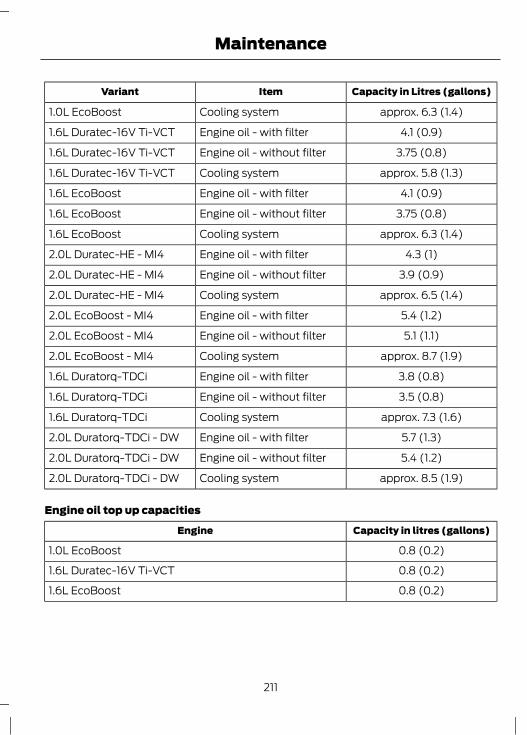
Capacity in Litres (gallons)ItemVariant
approx. 6.3 (1.4)Cooling system1.0L EcoBoost
4.1 (0.9)Engine oil - with filter1.6L Duratec-16V Ti-VCT
3.75 (0.8)Engine oil - without filter1.6L Duratec-16V Ti-VCT
approx. 5.8 (1.3)Cooling system1.6L Duratec-16V Ti-VCT
4.1 (0.9)Engine oil - with filter1.6L EcoBoost
3.75 (0.8)Engine oil - without filter1.6L EcoBoost
approx. 6.3 (1.4)Cooling system1.6L EcoBoost
4.3 (1)Engine oil - with filter2.0L Duratec-HE - MI4
3.9 (0.9)Engine oil - without filter2.0L Duratec-HE - MI4
approx. 6.5 (1.4)Cooling system2.0L Duratec-HE - MI4
5.4 (1.2)Engine oil - with filter2.0L EcoBoost - MI4
5.1 (1.1)Engine oil - without filter2.0L EcoBoost - MI4
approx. 8.7 (1.9)Cooling system2.0L EcoBoost - MI4
3.8 (0.8)Engine oil - with filter1.6L Duratorq-TDCi
3.5 (0.8)Engine oil - without filter1.6L Duratorq-TDCi
approx. 7.3 (1.6)Cooling system1.6L Duratorq-TDCi
5.7 (1.3)Engine oil - with filter2.0L Duratorq-TDCi - DW
5.4 (1.2)Engine oil - without filter2.0L Duratorq-TDCi - DW
approx. 8.5 (1.9)Cooling system2.0L Duratorq-TDCi - DW
Engine oil top up capacities
Capacity in litres (gallons)Engine
0.8 (0.2)1.0L EcoBoost
0.8 (0.2)1.6L Duratec-16V Ti-VCT
0.8 (0.2)1.6L EcoBoost
211
Maintenance

Capacity in litres (gallons)Engine
0.9 (0.2)2.0L Duratec-HE - MI4 and 2.0L EcoBoost - MI4
1.6 (0.4)1.6L Duratorq-TDCi
1.8 (0.4)2.0L Duratorq-TDCi - DW
212
Maintenance

CLEANING THE EXTERIOR
WARNINGIf you use a car wash with a waxingcycle, make sure that you remove thewax from the windscreen.
CAUTIONSPrior to using a car wash facility checkthe suitability of it for your vehicle.Some car wash installations usewater at high pressure. This coulddamage certain parts of your vehicle.Remove the aerial before using anautomatic car wash.Switch the heater blower off toprevent contamination of the fresh airfilter.
We recommend that you wash your vehiclewith a sponge and lukewarm watercontaining a car shampoo.
Cleaning the headlampsCAUTIONS
Do not scrape the headlamp lensesor use abrasives, alcoholic solvents orchemical solvents to clean them.Do not wipe the headlamps whenthey are dry.
Cleaning the rear windowCAUTION
Do not scrape the inside of the rearwindow or use abrasives or chemicalsolvents to clean it.
Use a clean, lint free cloth or a dampchamois leather to clean the inside of therear window.
Cleaning the chrome trimCAUTION
Do not use abrasives or chemicalsolvents. Use soapy water.
Cleaning the alloy wheelsNote: Do not apply a cleaning chemical towarm or hot wheel rims and covers.Note: Industrial-strength (heavy-duty)cleaners, or cleaning chemicals, incombination with brush agitation to removebrake dust and dirt, could wear away theclear coat finish over a period time.Note: Do not use hydrofluoric acid-basedor high caustic-based wheel cleaners, steelwool, fuels or strong household detergent.Note: If you intend parking your vehicle foran extended period after cleaning thewheels with a wheel cleaner, drive yourvehicle for a few minutes before doing so.This will reduce the risk of increasedcorrosion of the brake discs, brake pads andlinings.Note: Some automatic car washes maycause damage to the finish on your wheelrims and covers.Alloy wheels and wheel covers are coatedwith a clear coat paint finish. To maintaintheir condition we recommend that you:• Clean them weekly with the
recommended wheel and tyre cleaner.• Use a sponge to remove heavy
deposits of dirt and brake dustaccumulation.
• Rinse them thoroughly with apressurised stream of water when youhave completed the cleaning process.
We recommend that you use Ford servicewheel cleaner. Make sure that you readand follow the manufacturer’s instructions.
213
Vehicle Care

Using other non-recommended cleaningproducts can result in severe andpermanent cosmetic damage.
Body paintwork preservationCAUTIONS
Do not polish your vehicle in strongsunshine.Do not allow polish to touch plasticsurfaces. It could be difficult toremove.Do not apply polish to the windscreenor rear window. This could cause thewipers to become noisy and they may
not clear the window properly.
We recommend that you wax thepaintwork once or twice a year.
CLEANING THE INTERIORSeat belts
WARNINGSDo not use abrasives, or chemicalsolvents to clean them.Do not allow moisture to penetratethe seat belt retractor mechanism.
Clean the seat belts with interior cleaneror water applied with a soft sponge. Letthe seat belts dry naturally, away fromartificial heat.
Instrument cluster screens, LCDscreens, radio screens
WARNINGDo not use abrasives, alcoholicsolvents or chemical solvents toclean them.
Rear windowsCAUTIONS
Do not use any abrasive materials toclean the interior of the rear windows.Do not install stickers or labels to theinterior of the rear windows.
REPAIRING MINOR PAINTDAMAGE
CAUTIONRemove apparently harmless lookingsubstances from the paintworkimmediately (e.g. bird droppings, tree
resins, insect remains, tar spots, road saltand industrial fall out).
You should repair paintwork damagecaused by stones from the road or minorscratches as soon as possible. A choice ofproducts is available from your FordDealer. Read and follow themanufacturer’s instructions.
214
Vehicle Care

JUMP-STARTING THE VEHICLE
WARNINGDo not use fuel lines, engine rockercovers or the intake manifold asgrounding points.
CAUTIONSConnect batteries with only the samenominal voltage.Always use booster cables withinsulated clamps and adequate sizecable.Do not disconnect the battery fromthe vehicle’s electrical system.
To connect the booster cables
A
B
C D
E102925
Flat battery vehicleABooster battery vehicleBPositive connection cableCNegative connection cableD
1. Position the vehicles so that they donot touch one another.
2. Switch off the engine and any electricalequipment.
3. Connect the positive (+) terminal ofvehicle B with the positive (+) terminalof vehicle A (cable C).
4. Connect the negative (-) terminal ofvehicle B to the ground connection ofvehicle A (cable D). See Batteryconnection points (page 216).
215
Vehicle battery

CAUTIONSDo not connect to the negative (–)terminal of the flat battery.Make sure that the cables are clear ofany moving parts and fuel deliverysystem parts.
To start the engine1. Run the engine of vehicle B at
moderately high speed.2. Start the engine of vehicle A.3. Run both vehicles for a minimum of
three minutes before disconnecting thecables.
CAUTIONDo not switch on the headlamps whendisconnecting the cables. The peakvoltage could blow the bulbs.
Disconnect the cables in the reverse order.
CHANGING THE VEHICLEBATTERY
CAUTIONFor vehicles with Start-stop thebattery requirement is different. Itmust be replaced by one of exactly
the same specification as the original.
Note: Where applicable, the audio systemmust be reprogrammed with the keycode.The battery is located in the enginecompartment. See Maintenance (page196).
BATTERY CONNECTIONPOINTS
CAUTIONDo not connect to the negative (–)terminal of the flat battery.
E130431
The ground connection point is located tothe right of the battery near the enginecompartment fuse box.
216
Vehicle battery

GENERAL INFORMATION
CAUTIONSUse only approved wheel and tyresizes. Using other sizes could damagethe vehicle and will make the National
Type Approval invalid.If you change the diameter of the tyresfrom that fitted at the factory, thespeedometer may not display the
correct speed. Take the vehicle to yourdealer to have the engine managementsystem reprogrammed.
If you intend to change the size of thewheels from that fitted at the factory,check the suitability with your dealer.
Note: Check your tyre pressures regularlyto optimise fuel economy.A decal with tyre pressure data is locatedin the driver’s door opening at the B-pillar.Check and set the tyre pressure at theambient temperature in which you areintending to drive the vehicle and when thetyres are cold.
CHANGING A ROAD WHEELLocking wheel nutsYou can obtain a replacement lockingwheel nut key and replacement lockingwheel nuts from your dealer using thereference number certificate.
Vehicles with a spare wheelIf the spare wheel is exactly the same typeand size as the other fitted road wheels,you can replace the existing road wheelwith the spare wheel and continue to drivein the normal manner.If the spare wheel is different to the otherroad wheels, it will carry a yellow label withthe appropriate speed limit.
Refer to the following information beforechanging the road wheel.
WARNINGSDrive the shortest possible distances.
Do not fit more than one spare wheelon your vehicle at any one time.Do not carry out any tyre repairs ona spare wheel.Do not drive through an automaticcar wash.If you are unsure what type of sparewheel you have do not exceed 80km/h (50 mph).On vehicles with a 2.0L EcoBoostSCTi (MI4) engine, do not switchstability control off or select sport
mode if you have fitted a temporary sparewheel to your vehicle.
Only fit snow chains to specifiedtyres. See TechnicalSpecifications (page 227).
Note: The ground clearance of your vehiclemay be reduced. Take care when parkingnext to a kerb.Note: Your vehicle may exhibit someunusual driving characteristics.
Vehicle jackWARNINGS
The vehicle jack supplied with yourvehicle should only be used whenchanging a wheel in emergency
situations.Before using the vehicle jack, checkthat it is not damaged or deformedand that the thread is lubricated and
free from foreign matter.
217
Wheels and Tyres

WARNINGSNever place anything between thejack and the ground, or the jack andthe vehicle.
Note: Vehicles with a tyre repair kit are notequipped with a vehicle jack or a wheelbrace.It is recommended to use a workshop typehydraulic jack for changing betweensummer and winter tyres.Note: Use a jack with a minimum liftingcapacity of 1.5 tonnes and a lifting plate witha minimum diameter of 80 millimetres (3.1inches).
Vehicles without tyre repair kitYour vehicle jack, wheel brace, screw-intowing eye and wheel trim remover arelocated in the spare wheel well.
Jacking and lifting pointsWARNING
Use only the specified jacking points.If you use other positions, you maydamage the body, steering,
suspension, engine, braking system or thefuel lines.
E92658
A
B
Emergency use onlyAMaintenanceB
218
Wheels and Tyres

E93302
A
Small arrow-shaped marks on the sills Ashow the location of the jacking points.
E92932
E93020
Assembling the wheel braceWARNING
The screw-in towing eye has aleft-hand thread. Turn itanti-clockwise to install it. Make sure
that the towing eye is fully tightened.
E122502
Insert the screw-in towing eye into thewheel brace.
Removing the wheel trim
E122314
2
1
1. Insert the wheel trim remover.2. Remove the wheel trim.
219
Wheels and Tyres

Note: Make sure that you pull the wheeltrim remover at right angles to the trim.
Removing a road wheelWARNINGS
Park your vehicle in such a positionthat neither the traffic nor you arehindered or endangered.Set up a warning triangle.
Make sure that the vehicle is on firm,level ground with the wheels pointingstraight ahead.Switch off the ignition and apply theparking brake.If your vehicle has a manualtransmission, select first or reversegear. If it has an automatic
transmission, select park.Have the passengers leave thevehicle.Secure the diagonally oppositewheel with an appropriate block orwheel chock.Make sure that the arrows ondirectional tyres point in the directionof rotation when the vehicle is
moving forwards. If you have to fit a sparewheel with the arrows pointing in theopposite direction, have the tyre refittedin the correct direction by a properlytrained technician.
Do not work underneath the vehiclewhen it is supported only by a jack.Make sure that the jack is vertical tothe jacking point and the base is flaton the ground.
Note: Do not lay alloy wheels face downon the ground, this will damage the paint.
Note: The spare wheel is located under thefloor cover in the luggage compartment.1. Install the locking wheel nut key.
E121887
1
2
2. Slacken the wheel nuts.3. Jack up the vehicle until the tyre is clear
of the ground.4. Remove the wheel nuts and the wheel.
Installing a road wheelWARNINGS
Use only approved wheel and tyresizes. Using other sizes coulddamage the vehicle and will make
the National Type Approval invalid. SeeTechnical Specifications (page 227).
Do not fit run flat tyres on vehiclesthat were not originally fitted withthem. Please contact your dealer for
more details regarding compatibility.
220
Wheels and Tyres
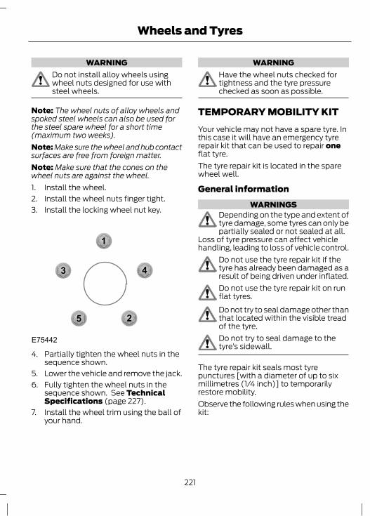
WARNINGDo not install alloy wheels usingwheel nuts designed for use withsteel wheels.
Note: The wheel nuts of alloy wheels andspoked steel wheels can also be used forthe steel spare wheel for a short time(maximum two weeks).Note: Make sure the wheel and hub contactsurfaces are free from foreign matter.Note: Make sure that the cones on thewheel nuts are against the wheel.1. Install the wheel.2. Install the wheel nuts finger tight.3. Install the locking wheel nut key.
1
2
3 4
5
E75442
4. Partially tighten the wheel nuts in thesequence shown.
5. Lower the vehicle and remove the jack.6. Fully tighten the wheel nuts in the
sequence shown. See TechnicalSpecifications (page 227).
7. Install the wheel trim using the ball ofyour hand.
WARNINGHave the wheel nuts checked fortightness and the tyre pressurechecked as soon as possible.
TEMPORARY MOBILITY KITYour vehicle may not have a spare tyre. Inthis case it will have an emergency tyrerepair kit that can be used to repair oneflat tyre.The tyre repair kit is located in the sparewheel well.
General informationWARNINGS
Depending on the type and extent oftyre damage, some tyres can only bepartially sealed or not sealed at all.
Loss of tyre pressure can affect vehiclehandling, leading to loss of vehicle control.
Do not use the tyre repair kit if thetyre has already been damaged as aresult of being driven under inflated.Do not use the tyre repair kit on runflat tyres.Do not try to seal damage other thanthat located within the visible treadof the tyre.Do not try to seal damage to thetyre’s sidewall.
The tyre repair kit seals most tyrepunctures [with a diameter of up to sixmillimetres (1/4 inch)] to temporarilyrestore mobility.Observe the following rules when using thekit:
221
Wheels and Tyres

• Drive with caution and avoidmaking sudden steering or drivingmanoeuvres, especially if the vehicleis heavily loaded or you are towing atrailer.
• The kit will provide you with anemergency temporary repair, enablingyou to continue your journey to the nextvehicle or tyre dealer, or to drive amaximum distance of 200 kilometres(125 miles).
• Do not exceed a maximum speed of80 km/h (50 mph).
• Keep the kit out of the reach ofchildren.
• Only use the kit when the ambienttemperature is between –30°C (-22°F)and +70°C (+158°F).
Using the tyre repair kitWARNINGS
Compressed air can act as anexplosive or propellant.Never leave the tyre repair kitunattended while in use.
CAUTIONDo not keep the compressor operatingfor more than 10 minutes.
Note: Use the tyre repair kit only for thevehicle with which it was supplied.• Park your vehicle at the roadside so
that you do not obstruct the flow oftraffic and so that you are able to usethe kit without being in danger.
• Apply the parking brake, even if youhave parked on a level road, to makesure that the vehicle will not move.
• Do not attempt to remove foreignobjects like nails or screws penetratingthe tyre.
• Leave the engine running while the kitis in use, but not if the vehicle is in anenclosed or poorly ventilated area (forexample, inside a building). In thesecircumstances, switch the compressoron with the engine turned off.
• Replace the sealant bottle with a newone before the expiry date (see top ofbottle) is reached.
• Inform all other users of the vehiclethat the tyre has been temporarilysealed with the tyre repair kit and makethem aware of the special drivingconditions to be observed.
Inflating the tyreWARNINGS
Check the sidewall of the tyre priorto inflation. If there are any cracks,bumps or similar damage, do not
attempt to inflate the tyre.Do not stand directly beside the tyrewhile the compressor is pumping.Watch the sidewall of the tyre. If anycracks, bumps or similar damageappear, turn off the compressor and
let the air out by means of the pressurerelief valve B. Do not continue driving withthis tyre.
The sealant contains natural rubberlatex. Avoid contact with skin andclothing. If this happens, rinse the
affected areas immediately with plenty ofwater and contact your doctor.
If the tyre inflation pressure does notreach 1.8 bar (26 psi) within sevenminutes, the tyre may have suffered
excessive damage, making a temporaryrepair impossible. In this case, do notcontinue driving with this tyre.
222
Wheels and Tyres
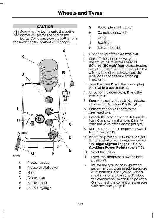
CAUTIONScrewing the bottle onto the bottleholder will pierce the seal of thebottle. Do not unscrew the bottle from
the holder as the sealant will escape.
E94973
BJ
I
FE
C
KA
G
H
D
Protective capAPressure relief valveBHoseCOrange capDBottle holderEPressure gaugeF
Power plug with cableGCompressor switchHLabelIBottle lidJSealant bottleK
1. Open the lid of the tyre repair kit.2. Peel off the label I showing the
maximum permissible speed of80 km/h (50 mph) from the casing andattach it to the instrument panel in thedriver’s field of view. Make sure thelabel does not obscure anythingimportant.
3. Take the hose C and the power plugwith cable G out of the kit.
4. Unscrew the orange cap D and thebottle lid J.
5. Screw the sealant bottle K clockwiseinto the bottle holder E fully tight.
6. Remove the valve cap from thedamaged tyre.
7. Detach the protective cap A from thehose C and screw the hose C firmlyonto the valve of the damaged tyre.
8. Make sure that the compressor switchH is in position 0.
9. Insert the power plug G into the cigarlighter socket or auxiliary power socket.See Cigar Lighter (page 116). SeeAuxiliary Power Points (page 116).
10. Start the engine.11. Move the compressor switch H to
position 1.12. Inflate the tyre for no longer than
seven minutes to an inflation pressureof minimum 1.8 bar (26 psi) and amaximum of 3.5 bar (51 psi). Movethe compressor switch H to position0 and check the current tyre pressurewith pressure gauge F.
223
Wheels and Tyres
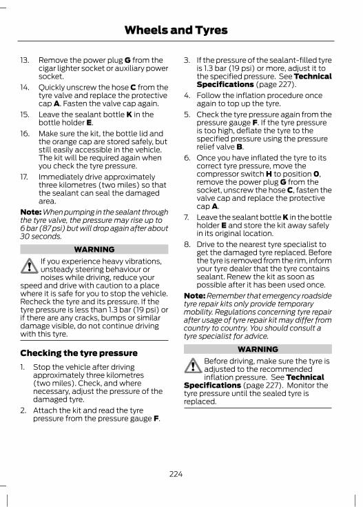
13. Remove the power plug G from thecigar lighter socket or auxiliary powersocket.
14. Quickly unscrew the hose C from thetyre valve and replace the protectivecap A. Fasten the valve cap again.
15. Leave the sealant bottle K in thebottle holder E.
16. Make sure the kit, the bottle lid andthe orange cap are stored safely, butstill easily accessible in the vehicle.The kit will be required again whenyou check the tyre pressure.
17. Immediately drive approximatelythree kilometres (two miles) so thatthe sealant can seal the damagedarea.
Note: When pumping in the sealant throughthe tyre valve, the pressure may rise up to6 bar (87 psi) but will drop again after about30 seconds.
WARNINGIf you experience heavy vibrations,unsteady steering behaviour ornoises while driving, reduce your
speed and drive with caution to a placewhere it is safe for you to stop the vehicle.Recheck the tyre and its pressure. If thetyre pressure is less than 1.3 bar (19 psi) orif there are any cracks, bumps or similardamage visible, do not continue drivingwith this tyre.
Checking the tyre pressure1. Stop the vehicle after driving
approximately three kilometres(two miles). Check, and wherenecessary, adjust the pressure of thedamaged tyre.
2. Attach the kit and read the tyrepressure from the pressure gauge F.
3. If the pressure of the sealant-filled tyreis 1.3 bar (19 psi) or more, adjust it tothe specified pressure. See TechnicalSpecifications (page 227).
4. Follow the inflation procedure onceagain to top up the tyre.
5. Check the tyre pressure again from thepressure gauge F. If the tyre pressureis too high, deflate the tyre to thespecified pressure using the pressurerelief valve B.
6. Once you have inflated the tyre to itscorrect tyre pressure, move thecompressor switch H to position 0,remove the power plug G from thesocket, unscrew the hose C, fasten thevalve cap and replace the protectivecap A.
7. Leave the sealant bottle K in the bottleholder E and store the kit away safelyin its original location.
8. Drive to the nearest tyre specialist toget the damaged tyre replaced. Beforethe tyre is removed from the rim, informyour tyre dealer that the tyre containssealant. Renew the kit as soon aspossible after it has been used once.
Note: Remember that emergency roadsidetyre repair kits only provide temporarymobility. Regulations concerning tyre repairafter usage of tyre repair kit may differ fromcountry to country. You should consult atyre specialist for advice.
WARNINGBefore driving, make sure the tyre isadjusted to the recommendedinflation pressure. See Technical
Specifications (page 227). Monitor thetyre pressure until the sealed tyre isreplaced.
224
Wheels and Tyres

Empty sealant bottles can be disposed oftogether with normal household waste.Return remains of sealant to your dealeror dispose of it in compliance with localwaste disposal regulations.
TYRE CARE
E70415
To make sure the front and rear tyres ofyour vehicle wear evenly and last longer,we recommend that you swap the tyresfrom front to rear and vice versa at regularintervals of between 5000 and 10000kilometres (3000 and 6000 miles).
CAUTIONDo not scrub the sidewalls of the tyreswhen you are parking.
If you have to mount a kerb, do so slowlyand approach it with the wheels atright-angles to the kerb.Examine the tyres regularly for cuts, foreignobjects and uneven wear of the tread.Uneven wear could mean that the wheelalignment is outside specification.Check the tyre pressures (including thespare) when cold, every two weeks.
USING WINTER TYRES
CAUTIONMake sure that you use the correctwheel nuts for the type of wheel thewinter tyres are fitted to.
If winter tyres are used, make sure that thetyre pressures are correct. See TechnicalSpecifications (page 227).
USING SNOW CHAINS
WARNINGSDo not exceed 50 km/h (30 mph).
Do not use snow chains on snow-freeroads.Only fit snow chains to specifiedtyres. See TechnicalSpecifications (page 227).
CAUTIONIf your vehicle is fitted with wheeltrims, remove them before fittingsnow chains.
Note: The ABS will continue to operatenormally.Only use small link snow chains.Only use snow chains on the front wheels.
Vehicles with stability control(ESP)Vehicles with stability control (ESP) mayexhibit some unusual drivingcharacteristics which can be reduced byswitching traction control off. See UsingStability Control (page 139).
225
Wheels and Tyres

USING SNOW CHAINS - 2.0LECOBOOST SCTI (MI4)
WARNINGSDo not exceed 50 km/h (30 mph).
Do not use snow chains on snow-freeroads.Only fit snow chains to specifiedtyres. See TechnicalSpecifications (page 227).If your vehicle is fitted with wheeltrims, remove them before fittingsnow chains.
Note: The ABS will continue to operatenormally.Only use snow chains of 12 millimetre orsmaller on 215/55 R 16 tyres.Only use snow chains of 10 millimetre orsmaller on 215/50 R 17 tyres.Only use snow chains on the front wheels.
Vehicles with stability control(ESP)Vehicles with stability control (ESP) mayexhibit some unusual drivingcharacteristics which can be reduced byswitching traction control off. See UsingActive City Stop (page 169).
TYRE PRESSUREMONITORING SYSTEM
WARNINGSThe system does not relieve you ofyour responsibility to regularly checkthe tyre pressures.The system will only provide a lowtyre pressure warning. It will notinflate the tyres.
WARNINGSDo not drive on significantlyunder-inflated tyres. This may causethe tyres to overheat and fail.
Under-inflation reduces fuel efficiency, tyretread life and may also affect your abilityto drive the vehicle safely.
CAUTIONSDo not bend or damage the valveswhen you are inflating the tyres.Have tyres installed by properlytrained technicians.
The Deflation Detection System will alertyou if there is a change of air pressure inany tyre. It does this by using the ABSsensors to detect the rolling circumferenceof the wheels. When the circumferencechanges, this indicates low pressure in atyre, a warning message is displayed in theinformation display and the messageindicator will illuminate. See InformationMessages (page 86).If a low pressure warning message isdisplayed in the information display, checkthe tyre pressures as soon as possible andinflate them to the recommendedpressure. See Technical Specifications(page 227).If this happens frequently, have the causedetermined and rectified as soon aspossible.Apart from a too low tyre pressure or adamaged tyre, the following situations canaffect the rolling circumference:• Vehicle load is uneven.• When using a trailer or travelling up and
down an incline.• Using snow chains.• Driving on soft surfaces such as snow
or mud.
226
Wheels and Tyres
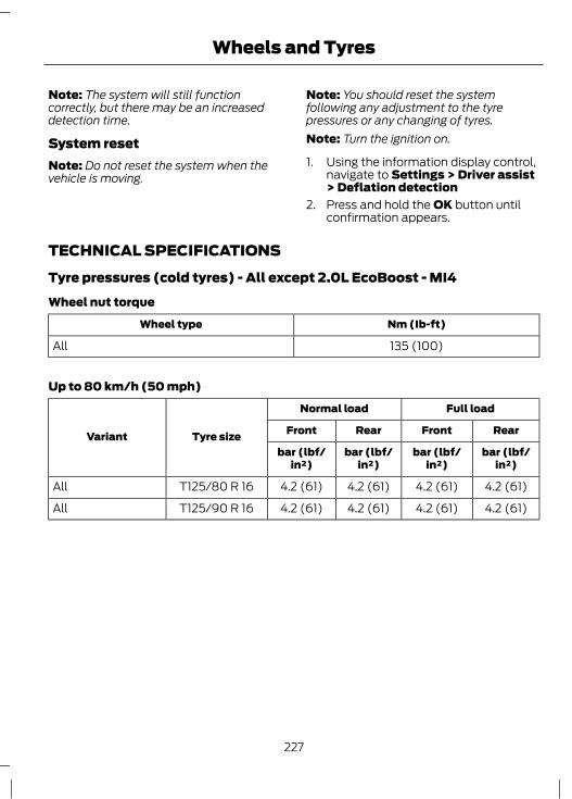
Note: The system will still functioncorrectly, but there may be an increaseddetection time.
System resetNote: Do not reset the system when thevehicle is moving.
Note: You should reset the systemfollowing any adjustment to the tyrepressures or any changing of tyres.Note: Turn the ignition on.
1. Using the information display control,navigate to Settings > Driver assist> Deflation detection
2. Press and hold the OK button untilconfirmation appears.
TECHNICAL SPECIFICATIONSTyre pressures (cold tyres) - All except 2.0L EcoBoost - MI4Wheel nut torque
Nm (Ib-ft)Wheel type
135 (100)All
Up to 80 km/h (50 mph)
Full loadNormal load
Tyre sizeVariant RearFrontRearFront
bar (lbf/in²)
bar (lbf/in²)
bar (lbf/in²)
bar (lbf/in²)
4.2 (61)4.2 (61)4.2 (61)4.2 (61)T125/80 R 16All
4.2 (61)4.2 (61)4.2 (61)4.2 (61)T125/90 R 16All
227
Wheels and Tyres

Up to 160 km/h (100 mph)
Full loadNormal load
Tyre sizeVariant RearFrontRearFront
bar (psi)bar (psi)bar (psi)bar (psi)
2.8 (41)2.4 (35)2.1 (31)2.1 (31)205/55 R 16*All
2.8 (41)2.4 (35)2.1 (31)2.1 (31)215/55 R 16*
1.0L EcoBoost, 1.6LDuratec-16V Ti-VCT, 1.6L EcoBoost,2.0L Duratec-HE -MI4, 1.6L Duratorq-TDCi
2.8 (41)2.4 (35)2.1 (31)2.3 (33)215/55 R 16*2.0L Duratorq-TDCi- DW
2.8 (41)2.4 (35)2.1 (31)2.1 (31)215/50 R 17
1.0L EcoBoost, 1.6LDuratec-16V Ti-VCT, 1.6L EcoBoost,2.0L Duratec-HE -MI4, 1.6L Duratorq-TDCi
2.8 (41)2.4 (35)2.1 (31)2.3 (33)215/50 R 172.0L Duratorq-TDCi- DW
2.8 (41)2.4 (35)2.1 (31)2.1 (31)235/40 R 18
1.6L Duratec-16V Ti-VCT, 1.6L EcoBoost,2.0L Duratec-HE -MI4, 1.6L Duratorq-TDCi
2.8 (41)2.4 (35)2.1 (31)2.3 (33)235/40 R 182.0L Duratorq-TDCi- DW
*Only fit snow chains to specified tyres.
228
Wheels and Tyres
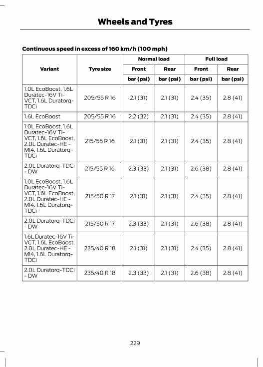
Continuous speed in excess of 160 km/h (100 mph)
Full loadNormal load
Tyre sizeVariant RearFrontRearFront
bar (psi)bar (psi)bar (psi)bar (psi)
2.8 (41)2.4 (35)2.1 (31)2.1 (31)205/55 R 161.0L EcoBoost, 1.6LDuratec-16V Ti-VCT, 1.6L Duratorq-TDCi
2.8 (41)2.4 (35)2.1 (31)2.2 (32)205/55 R 161.6L EcoBoost
2.8 (41)2.4 (35)2.1 (31)2.1 (31)215/55 R 16
1.0L EcoBoost, 1.6LDuratec-16V Ti-VCT, 1.6L EcoBoost,2.0L Duratec-HE -MI4, 1.6L Duratorq-TDCi
2.8 (41)2.6 (38)2.1 (31)2.3 (33)215/55 R 162.0L Duratorq-TDCi- DW
2.8 (41)2.4 (35)2.1 (31)2.1 (31)215/50 R 17
1.0L EcoBoost, 1.6LDuratec-16V Ti-VCT, 1.6L EcoBoost,2.0L Duratec-HE -MI4, 1.6L Duratorq-TDCi
2.8 (41)2.6 (38)2.1 (31)2.3 (33)215/50 R 172.0L Duratorq-TDCi- DW
2.8 (41)2.4 (35)2.1 (31)2.1 (31)235/40 R 18
1.6L Duratec-16V Ti-VCT, 1.6L EcoBoost,2.0L Duratec-HE -MI4, 1.6L Duratorq-TDCi
2.8 (41)2.6 (38)2.1 (31)2.3 (33)235/40 R 182.0L Duratorq-TDCi- DW
229
Wheels and Tyres

Tyre pressures (cold tyres) - 2.0L EcoBoost - MI4Wheel nut torque
Nm (Ib-ft)Wheel type
135 (100)All
Temporary spare wheel - Up to 80 km/h (50 mph)WARNING
Do not switch stability control off if you have fitted a temporary spare wheel to yourvehicle.
Full loadNormal load
Tyre size RearFrontRearFront
bar (lbf/in²)bar (lbf/in²)bar (lbf/in²)bar (lbf/in²)
4.2 (61)4.2 (61)4.2 (61)4.2 (61)T125/80 R 16
4.2 (61)4.2 (61)4.2 (61)4.2 (61)T125/90 R 16
Temporary spare wheel - Up to 120 km/h (75 mph)WARNING
Do not switch stability control off if you have fitted a temporary spare wheel to yourvehicle.
Full loadNormal load
Tyre size RearFrontRearFront
bar (lbf/in²)bar (lbf/in²)bar (lbf/in²)bar (lbf/in²)
3 (44)3 (44)3 (44)3 (44)205/55 R 16
230
Wheels and Tyres

Up to 220 km/h (137 mph)
Full loadNormal load
Tyre size RearFrontRearFront
bar (psi)bar (psi)bar (psi)bar (psi)
2.8 (41)2.4 (35)2.4 (35)2.4 (35)215/55 R 16*
2.8 (41)2.4 (35)2.4 (35)2.4 (35)215/50 R 17*
2.4 (35)2.4 (35)2.4 (35)2.4 (35)235/40 R 18*Only fit snow chains to specified tyres.
Continuous speed in excess of 220 km/h (137 mph)
Full loadNormal load
Tyre size RearFrontRearFront
bar (psi)bar (psi)bar (psi)bar (psi)
2.8 (41)2.6 (38)2.4 (35)2.4 (35)215/55 R 16
2.8 (41)2.8 (41)2.4 (35)2.5 (36)215/50 R 17
2.5 (36)2.5 (36)2.4 (35)2.4 (35)235/40 R 18
231
Wheels and Tyres

VEHICLE IDENTIFICATIONPLATE
Note: The vehicle identification platedesign may vary to that shown.Note: The information shown on the vehicleidentification plate is dependant uponmarket requirements.
E135662
B C ED
F
G
H
I
A
ModelAVariantBEngine designationCEmission levelDVehicle identification numberEGross vehicle weightFGross train weightGMaximum front axle weightHMaximum rear axle weightI
The vehicle identification number andmaximum weights are shown on a platelocated on the lock side of the right-handdoor aperture at the bottom.
232
Vehicle identification

VEHICLE IDENTIFICATIONNUMBER
E87496
The vehicle identification number isstamped into the floor panel on theright-hand side, beside the front seat. It isalso shown on the left-hand side of theinstrument panel.
233
Vehicle identification

TECHNICAL SPECIFICATIONSVehicle dimensions4-door
Dimension in mm (inches)Dimension description
4534 (178.5)Maximum length
2010 (79.1)Overall width including exterior mirrors
1451 - 1484 (57.1 - 58.4)Overall height - EC kerb weight
2648 (104.3)Wheelbase
1544 - 1559 (60.8 - 61.4)Front track
1534 - 1549 (60.4 - 61)Rear track
5-door
Dimension in mm (inches)Dimension description
4358 - 4412 (171.6 - 173.7)Maximum length
2010 (79.1)Overall width including exterior mirrors
1451 - 1484 (57.1 - 58.4)Overall height - EC kerb weight
2648 (104.3)Wheelbase
1544 - 1559 (60.8 - 61.4)Front track
1534 - 1549 (60.4 - 61)Rear track
Estate
Dimension in mm (inches)Dimension description
4556 - 4606 (179.4 - 181.3)Maximum length
2010 (79.1)Overall width including exterior mirrors
1472 - 1505 (58 - 59.3)Overall height - EC kerb weight
234
Capacities and Specifications

Dimension in mm (inches)Dimension description
2648 (104.3)Wheelbase
1544 - 1559 (60.8 - 61.4)Front track
1534 - 1549 (60.4 - 61)Rear track
235
Capacities and Specifications

Towing equipment dimensions
A
B
G
F
E
C
D
E132737
236
Capacities and Specifications
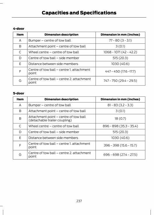
4-door
Dimension in mm (inches)Dimension descriptionItem
77 - 80 (3 - 3.1)Bumper – centre of tow ballA
3 (0.1)Attachment point – centre of tow ballB
1068 - 1071 (42 - 42.2)Wheel centre – centre of tow ballC
515 (20.3)Centre of tow ball – side memberD
1030 (40.6)Distance between side membersE
447 - 450 (17.6 -17.7)Centre of tow ball – centre 1. attachmentpointF
747 - 750 (29.4 - 29.5)Centre of tow ball – centre 2. attachmentpointG
5-door
Dimension in mm (inches)Dimension descriptionItem
81 - 83 (3.2 - 3.3)Bumper – centre of tow ballA
3 (0.1)Attachment point – centre of tow ballB
18 (0.7)Attachment point – centre of tow ball(detachable trailer coupling)B
896 - 898 (35.3 - 35.4)Wheel centre – centre of tow ballC
515 (20.3)Centre of tow ball – side memberD
1030 (40.6)Distance between side membersE
396 - 398 (15.6 - 15.7)Centre of tow ball – centre 1. attachmentpointF
696 - 698 (27.4 - 27.5)Centre of tow ball – centre 2. attachmentpointG
237
Capacities and Specifications

Estate
Dimension in mm (inches)Dimension descriptionItem
81 (3.2)Bumper – centre of tow ballA
72 - 77 (2.8 - 3)Attachment point – centre of tow ballB
1094 (43.1)Wheel centre – centre of tow ballC
586 (23.1)Centre of tow ball – side memberD
1172 (46.1)Distance between side membersE
474 (18.7)Centre of tow ball – centre 1. attachmentpointF
719 (28.3)Centre of tow ball – centre 2. attachmentpointG
238
Capacities and Specifications

IMPORTANT AUDIOINFORMATION
WARNINGSDue to technical incompatibility,recordable (CD-R) and rewritable(CD-RW) discs may not function
correctly.These CD radio units will playcompact discs that conform to theInternational Red Book standard
audio specification. Copy protected CDsfrom some manufacturers do not conformto this standard and playback cannot beguaranteed.
Dual format, dual sided discs (DVDPlus, CD-DVD format), adopted bythe music industry, are thicker than
normal CDs and consequently playbackcannot be guaranteed, and jamming couldoccur. Irregular shaped CDs and CDs witha scratch protection film or self adhesivelabels attached should not be used.Warranty claims, where this type of disc isfound to be inside an audio unit returnedfor repair, will not be accepted.
All CD units are designed to playcommercially pressed 12 cm audiocompact discs only.The audio unit may be damaged ifunsuitable items like credit cards orcoins are pushed inside the CD
aperture.
Audio unit labels
E66256
E66257
Disc labelsAudio CD
E66254
MP3
E66255
239
Audio introduction

Note: Units have an integrated multifunction display situated above the CDaperture. This shows important informationregarding control of your audio unit.Additionally, there are various icons placedaround the display screen which light upwhen a function is active (for example CD,Radio or Aux.)Type 1
A B ED
FO
G
K
L
M
N
J HI
C
E130324
CD eject. See Compact Disc Player (page 252).ANavigation arrows.BCD aperture. See Compact Disc Player (page 252).COK.DInformation.ETraffic announcement. See Traffic information control (page 248).FStation presets. See Station preset buttons (page 248).G
240
Audio unit overview

Seek up. CD track selection. See Station tuning control (page 247). See Trackselection (page 252).
H
On/off and volume control.ISeek down. CD track selection. See Station tuning control (page 247). SeeTrack selection (page 252).
J
Menu select.KSound button. See Sound button (page 247).LAuxiliary select. See Auxiliary input (AUX IN) socket (page 255). SeeAuxiliary input (AUX IN) socket (page 255).
M
Radio and waveband select. See Audio unit operation (page 247).NCD select. See Compact Disc Player (page 252).O
Type 2
E104157 A
1 2 3 4
Descriptions for function buttons1-4
A
241
Audio unit overview

A B EDT
H
F
G
P
Q
R
S
MO N J IKL
C
E130142
CD eject. See Compact Disc Player (page 252).ANavigation arrows.BCD aperture. See Compact Disc Player (page 252).COK.DInformation.ETraffic announcement. See Traffic information control (page 248).FSound button. See Sound button (page 247).GTelephone keypad and station presets. See Using the telephone (page 258).See Station preset buttons (page 248).
H
Function 4.IFunction 3.JSeek up. CD track selection. See Station tuning control (page 247). See Trackselection (page 252).
K
242
Audio unit overview

On/off and volume control.LSeek down. CD track selection. See Station tuning control (page 247). SeeTrack selection (page 252).
M
Function 2.NFunction 1.OMenu select.PPhone menu. See Telephone (page 257).QAuxiliary, USB and iPod select. See Auxiliary input (AUX IN) socket (page255). See Auxiliary input (AUX IN) socket (page 255). See Connectivity(page 277).
R
Radio and waveband select. See Audio unit operation (page 247).SCD select. See Compact Disc Player (page 252).T
Function buttons 1 to 4 are contextdependent, and change according to thecurrent unit mode. Descriptions for thefunctions are shown at the bottom of thescreen display.
Type 3
E104157 A
1 2 3 4
Descriptions for function buttons1-4
A
243
Audio unit overview

E129074
A CB FE
Y
I
G
H
J
L
KT
U
W
X
V
QS R N MOP
D
On/off control.ADisplay select.BTelephone keypad and station presets. See Using the telephone (page 258).See Station preset buttons (page 248).
C
CD aperture. See Compact Disc Player (page 252).DNavigation arrows.EDSP select. See Digital signal processing (DSP) (page 250).FCD eject. See Compact Disc Player (page 252).GInformation.HClock.ISeek up. CD track selection. End call. See Station tuning control (page 247).See Track selection (page 252). See Using the telephone (page 258).
J
Mute.K
244
Audio unit overview
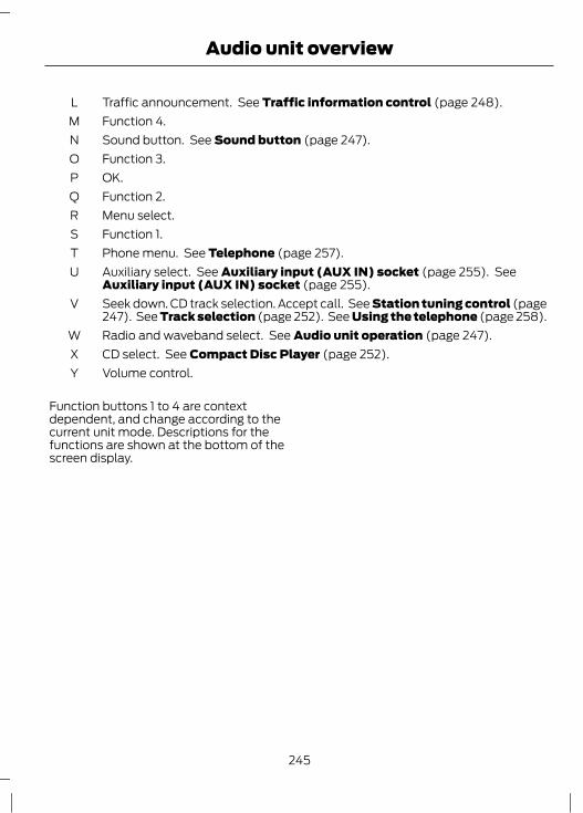
Traffic announcement. See Traffic information control (page 248).LFunction 4.MSound button. See Sound button (page 247).NFunction 3.OOK.PFunction 2.QMenu select.RFunction 1.SPhone menu. See Telephone (page 257).TAuxiliary select. See Auxiliary input (AUX IN) socket (page 255). SeeAuxiliary input (AUX IN) socket (page 255).
U
Seek down. CD track selection. Accept call. See Station tuning control (page247). See Track selection (page 252). See Using the telephone (page 258).
V
Radio and waveband select. See Audio unit operation (page 247).WCD select. See Compact Disc Player (page 252).XVolume control.Y
Function buttons 1 to 4 are contextdependent, and change according to thecurrent unit mode. Descriptions for thefunctions are shown at the bottom of thescreen display.
245
Audio unit overview

SECURITY CODEEach unit incorporates a unique code thatis linked to the vehicle identificationnumber (VIN). The system willautomatically check that the audio unitand vehicle match before allowingoperation.If a security code message appears, pleasesee your dealer.
246
Audio System Security

ON/OFF CONTROLPress the button with the ignition switchedoff. This will operate the audio unit for upto one hour.If you switch the audio unit on before youswitch the ignition off, the audio unit willswitch off automatically after 10 minutesor when you open one of the front doors.
SOUND BUTTONThis will allow you to adjust the soundsettings (for example bass and treble).1. Press the sound button.2. Use the up and down arrow buttons to
select the required setting.3. Use the left and right arrow buttons to
make the necessary adjustment. Thedisplay indicates the level selected.
4. Press the OK button to confirm thenew settings.
WAVEBAND BUTTONPress the RADIO button to select from thewavebands available.The selector can also be used to return toradio reception when you have beenlistening to another source.Alternatively, press the left arrow buttonto display the available wavebands. Scrollto the required waveband and press OK.
STATION TUNING CONTROLDAB service linkingNote: The DAB service linking is as perdefault off.
Note: Service linking allowscross-referencing to other correspondingfrequencies of the same station, for exampleFM and other DAB ensembles.Note: The system will automaticallychange to another corresponding station ifthe current one becomes unavailable, forexample when leaving the coverage area.Switching DAB service linking on and off.See General Information (page 78).
Seek tuningSelect a waveband and briefly press oneof the seek buttons. The unit will stop atthe first station it finds in the direction youhave chosen.
Manual tuningType 11. Press the MENU button.2. Select RADIO mode and then MANUAL
TUNE.3. Use the left and right arrow buttons to
tune down or up the waveband in smallincrements or press and hold toincrement quickly, until you find astation you want to listen to.
4. Press OK to continue listening to astation.
Type 2 and 31. Press function button 2.2. Use the left and right arrow buttons to
tune down or up the waveband in smallincrements or press and hold toincrement quickly, until you find astation you want to listen to.
3. Press OK to continue listening to astation.
247
Audio unit operation

Scan tuningScan allows you to listen to a few secondsof each station detected.
Type 11. Press the MENU button.2. Select RADIO mode and then SCAN.3. Use the seek buttons to scan up or
down the selected waveband.4. Press OK to continue listening to a
station.
Type 2 and 31. Press function button 3.2. Use the seek buttons to scan up or
down the selected waveband.3. Press function button 3 again or OK to
continue listening to a station.
STATION PRESET BUTTONSThis feature allows you to store yourfavourite stations so that they can berecalled by selecting the appropriatewaveband and pressing one of the presetbuttons.1. Select a waveband.2. Tune to the station required.3. Press and hold one of the preset
buttons. A progress bar and messagewill appear. When the progress barcompletes the station has been stored.The audio unit will also mutemomentarily as confirmation.
This can be repeated on each wavebandand for each preset button.Note: When you drive to another part of thecountry, FM and DAB stations thatbroadcast on alternative frequencies, andare stored on preset buttons, may beupdated with the correct frequency andstation name for that area.
AUTOSTORE CONTROLNote: This will store up to a maximum ofthe 10 strongest signals available, eitherfrom the AM or the FM waveband, andoverwrite the previously stored stations. Itcan also be used to store stations manuallyin the same way as other wavebands.Note: On type 3 you must select either FMAST or AM AST to use this function.• Press and hold function button 1 or the
RADIO button.• When the search is complete, sound is
restored and the strongest signals arestored on the Autostore presets.
TRAFFIC INFORMATIONCONTROLMany stations that broadcast on the FMwaveband have a TP code to signify thatthey carry traffic programme information.
Activating traffic announcementsBefore you can receive trafficannouncements, you must press either theTA or TRAFFIC button. A ‘TA’ display willappear to show the feature is switched on.If you are already tuned to a station thatbroadcasts traffic information, ‘TP’ willalso be displayed. Otherwise the unit willsearch for a traffic programme.When traffic information is broadcast, itwill automatically interrupt normal radioor CD playback and ‘Traffic announcement(TA)’ will appear in the display.If a non-traffic station is selected orrecalled using a preset button, the audiounit will remain on that station unless TAor TRAFFIC is turned off, then on again.Note: If TA is on and you select a preset ormanual tune to a non TA station no trafficannouncement will be heard.
248
Audio unit operation

Note: When you are listening to a non TAstation and turn TA off and on again a TPseek will occur.
Traffic announcement volumeTraffic announcements interrupt normalbroadcasts at a preset minimum level thatis usually louder than normal listeningvolumes.To adjust the preset volume:• Use the volume control to make the
necessary adjustment during anincoming TA broadcast. The displaywill show the level selected.
Ending traffic announcementsThe audio unit will return to normaloperation at the end of each trafficannouncement. To end the announcementprematurely, press TA or TRAFFIC duringthe announcement.Note: If you press TA or TRAFFIC at anyother time it will switch all announcementsoff.
249
Audio unit operation
AUTOMATIC VOLUMECONTROLWhen available, automatic volume control(AVC) adjusts the volume level tocompensate for engine noise and roadspeed noise.1. Press the MENU button and select
AUDIO.2. Select AVC LEVEL or ADAPTIVE VOL.3. Use the left or right arrow button to
adjust the setting.4. Press the OK button to confirm your
selection.5. Press the MENU button to return.
DIGITAL SIGNAL PROCESSING(DSP)DSP occupancyThis feature takes into account thedifferences in distance from the variousspeakers in the vehicle to each seat. Selectthe sitting position for which the audio isto be correctly enhanced.
DSP equaliserSelect the music category that most suitsyour listening preference. The audio outputwill change to enhance the particular styleof music chosen.
Changing the DSP settings1. Press the MENU button.2. Select AUDIO or AUDIO SETTINGS.3. Scroll to the required DSP function.4. Use the up and down arrow buttons to
select the required setting.5. Press the OK button to confirm your
selection.6. Press the MENU button to return.
NEWS BROADCASTSSome audio units interrupt normalreception to broadcast news bulletins fromstations on the FM waveband or radio datasystem (RDS) and enhanced othernetwork (EON) linked stations, in the sameway as traffic information is provided.During news broadcasts, the display willindicate there is an incomingannouncement. News interrupts arebroadcast at the same preset volume levelas traffic announcements.1. Press the MENU button.2. Select AUDIO or AUDIO SETTINGS.3. Scroll to NEWS and turn on or off with
the OK button.4. Press the MENU button to return.
ALTERNATIVE FREQUENCIESMany programmes that broadcast on theFM waveband have a programmeidentification (PI) code, which can berecognised by audio units.If your radio has alternative frequencies(AF) tuning switched on and you movefrom one transmission area to another, thisfacility will search for and switch to astronger station signal, if one can be found.Under certain conditions, however, AFtuning may temporarily disrupt normalreception.When selected, the unit continuallyevaluates signal strength and, if a bettersignal becomes available, the unit willswitch to that alternative. It mutes whileit checks a list of alternative frequenciesand, if necessary, it will search once acrossthe selected waveband for a genuinealternative frequency.
250
Audio unit menus

It will restore radio reception when it findsone or, if one is not found, the unit willreturn to the original stored frequency.When selected, ‘AF’ will be shown in thedisplay.1. Press the MENU button.2. Select AUDIO or AUDIO MENU.3. Scroll to ALTERNAT FREQ. or
ALTERNATIVE FREQ. and turn on or offwith the OK button.
4. Press the MENU button to return.
REGIONAL MODE (REG)Regional mode (REG) controls thebehaviour of AF switching betweenregionally related networks of a parentbroadcaster. A broadcaster may run a fairlylarge network across a large part of thecountry. At various times of the day thislarge network may be broken down into anumber of smaller regional networks,typically centred on major towns or cities.When the network is not split into regionalvariants, the whole network caries thesame programming.Regional mode ON: This prevents 'random'AF switches when neighbouring regionalnetworks are not carrying the sameprogramming.Regional mode OFF: This allows a largercoverage area if neighbouring regionalnetworks are carrying the sameprogramming, but can cause 'random' AFswitches if they are not.1. Press the MENU button.2. Select AUDIO or AUDIO SETTINGS.3. Scroll to RDS REGIONAL and turn on
or off with the OK button.4. Press the MENU button to return.
251
Audio unit menus

COMPACT DISC PLAYBACKNote: During playback, the display indicatesthe disc, track and time that has elapsedsince the start of the track.During radio reception, press the CD buttononce to start CD playback.Playback will start immediately after a discis loaded.
TRACK SELECTION• Press the seek up button once to move
to the next track or press it repeatedlyto access later tracks.
• Press the seek down button once toreplay the current track. If pressedwithin two seconds of the start of atrack, the previous track will beselected.
• Press the seek down button repeatedlyto select previous tracks.
• Press the up or down arrow buttons,and using the OK button, select therequired track.
Type 2 and 3The desired track number may be enteredusing the numeric keypad. Dial the requiredtrack number until complete (for example1 then 2 for track 12), or dial the numberand directly press OK.
FAST FORWARD/REVERSEPress and hold the seek down or upbuttons to search backwards or forwardswithin the tracks on the disc.
SHUFFLE/RANDOMRandom track playback, also known asshuffle, plays all tracks on the CD inrandom order.
Type 11. Press the MENU button and select CD
MODE.2. Select SHUFFLE, which then enables
the function to be selected on or off.When an MP3 CD is playing, optionsinclude SHUFFLE for the whole CD, or toplay all the tracks in the folder in a randomorder.
Type 2 and 3Press function button 2.Note: When an MP3 CD is playing, optionsinclude SHUFFLE for the whole CD, or toplay all the tracks in the folder in a randomorder. Repeat presses of function button 2will toggle these options.Use the seek up or down button to selectthe next track to shuffle if required.
REPEAT COMPACT DISCTRACKSType 11. Press the MENU button and select CD
MODE.2. Select REPEAT, which then enables
the function to be selected on or off.The track will replay once ended.
When an MP3 CD is playing, optionsinclude REPEAT for the track, or to repeatall the tracks in the folder.
Type 2 and 3Press function button 1.
252
Compact Disc Player

When an MP3 CD is playing, optionsinclude REPEAT for the track, or to repeatall the tracks in the folder. Repeat pressesof function button 1 will toggle theseoptions.
COMPACT DISC TRACKSCANNINGThe SCAN function allows you to previeweach track for approximately 5 seconds.
Type 1Various scan modes are possible,according to the type of CD currentlyplaying.1. Press the MENU button and select CD
MODE.2. Select SCAN, which then enables the
function to be selected on or off.Note: When an MP3 CD is playing, optionsinclude SCAN for the CD, or just the tracksin the folder.3. Press the OK button to stop the scan
mode.
Type 2 and 31. Press function button 3.Note: When an MP3 CD is playing, optionsinclude SCAN for the CD, or just the tracksin the folder. Repeat presses of functionbutton 3 will toggle these options.2. Press function button 3 again to stop
the scan mode.
MP3 FILE PLAYBACKNote: Some copy protected audio files maynot be read by the CD player.The CD player also supports MP3 andWMA format audio files.
When a CD containing audio is insertedinto the CD player the disc's directorystructure is read in. It may take a whilebefore playback starts and is dependanton the quality of the disc.MP3 tracks may be recorded on the CD inseveral ways. They can all be placed in theroot directory like a conventional audio CD,or they can be placed in folders that mayrepresent, for example, an album, an artist,or a genre.
Playing a multi session discThe normal playing sequence on CD's withmultiple folders is to play the tracks in thefirst folder, then the tracks in any foldersnested inside the first folder, then moveonto the second folder, and so on. Forexample, if folder 1 has folders 1a and 1bwithin it, and folder 2 contains folder 2a,the playing sequence will be folder 1, 1a, 1b,2, 2a.When the playback of a file is finished theplayback of the other files in the samedirectory continues. Directory change takesplace automatically when all files in thecurrent directory have been played back.
MP3 DISPLAY OPTIONSWhen an MP3 disc is playing, certaininformation encoded in each track can bedisplayed. Such information will normallyinclude:• The file name• The folder name• ID3 information which might be the
album or artist’s name.The unit will normally show the file namethat is playing. To select one of the otheritems of information, press the INFObutton repeatedly until the required itemis shown in the display.
253
Compact Disc Player

Note: If the ID3 information selected isunavailable, NO MP3 TAG will be shown inthe display.
CD text display optionsWhen an audio disc with CD text is playing,limited information encoded in each trackcan be displayed. Such information willnormally include:• The disc name• The artist name• The track name.Note: These display options are selectedin the same way as MP3 displays. NO DISCNAME or NO TRACK NAME will be shownin the display if no information has beenencoded.
ENDING COMPACT DISCPLAYBACKTo restore radio reception on all units:• Press the RADIO button.Note: This will not eject the CD; the discwill merely pause at the point where radioreception was restored.To resume CD playback, press the CDbutton again.
254
Compact Disc Player

Note: For optimum performance whenusing any auxiliary device set the volume onthe device high. This will reduce audiointerference when charging the device viathe vehicle power supply socket.When fitted the Auxiliary input (AUX IN)socket permits an auxiliary device, such asan MP3 player, to be linked into the vehicleaudio system. Output can be playedthrough the vehicle speakers.To connect an auxiliary device, plug it intothe AUX IN socket using a 3.5 mmconventional audio jack connector.Select the auxiliary input via the AUXbutton and playback will be heard throughthe vehicle speakers. LINE IN or LINE INACTIVE will appear in the vehicle audiounit display. Volume, treble and bass canbe adjusted on the vehicle audio unit asnormal.The vehicle audio unit buttons can also beused to restore playback from the vehicleaudio unit, while the auxiliary deviceremains connected.
255
Auxiliary input (AUX IN) socket

AUDIO TROUBLESHOOTING
RectificationAudio unit display
General error message for CD fault conditions, such ascannot read the CD, data-CD inserted, etc. Ensure discis loaded correct way up. Clean and re-try, or replace
disc with known music disc. If error persists contact yourdealer.
PLEASE CHECK CD
General error message for CD fault conditions such aspossible mechanism fault.
CD DRIVE MALFUNCTION
Ambient temperature too hot – unit will not work untilit has cooled down.
CD DRIVE HIGH TEMP
General error message for iPod fault conditions, suchas cannot read the data. Ensure iPod is inserted
correctly. If error persists contact your dealer.
IPOD ERROR READING DEVICE
256
Audio Troubleshooting

GENERAL INFORMATION
CAUTIONUsing the system with the engine offwill drain the battery.
This section describes the functions andfeatures of the Bluetooth mobile phonehands free system.The Bluetooth mobile phone part of thesystem provides interaction with the audioor navigation system and your mobilephone. It allows you to use the audio ornavigation system to make and receivecalls without having to hold your mobilephone.
Compatibility of phonesCAUTION
As no common agreement exists,mobile phone manufacturers are ableto implement a variety of profiles in
their Bluetooth devices. Because of this,an incompatibility can occur between thephone and hands-free system, which insome cases may significantly degrade thesystem performance. To avoid thissituation, only recommended phonesshould be used.
Please visit the website www.ford-mobile-connectivity.com for full details.
BLUETOOTH SETUPBefore you can use your telephone withyour vehicle it must be bonded to thevehicle telephone system.
Handling of phonesUp to six Bluetooth devices can be bondedto the vehicle system.
Note: If there is an ongoing call when thephone in use is selected as the new activephone, the call is transferred to the vehicleaudio system.Note: Even if connected to the car system,your phone can still be used in the usualway.
Requirements for BluetoothconnectionThe following are required before aBluetooth phone connection can be made.1. The Bluetooth feature must be
activated on the phone and on theaudio unit. Make sure the Bluetoothmenu option in the audio unit is set toON. For information on phone settings,refer to your phone user guide.
2. In the Bluetooth menu on your phone,search for Ford Audio and select it.
3. Enter the code number shown on thevehicle display using the phone keypad.If no code number is shown on thedisplay, enter the Bluetooth PINnumber 0000 using the phone keypad.Now enter the Bluetooth PIN numbershown on the vehicle display.
4. If your mobile phone asks you toauthorize the automatic connection,select YES.
Note: A phone call will be disconnected ifthe audio unit is switched off. If the ignitionkey is turned to the off position the phonecall will remain in progress.
TELEPHONE SETUPPhonebookNote: It may be necessary to confirmphonebook access to the Bluetooth systemvia the mobile phone.
257
Telephone

After start up access to the phonebook listcan be delayed for several minutes,depending upon the size.
Phonebook categoriesThe category is indicated as an icon:
E87990
Phone
E87991
Mobile
E87992
Home
E87993
Office
Making a phone an active phoneNote: If there is an ongoing call when thephone in use is selected as the new activephone, the call is transferred to the vehicleaudio system.When using the system for the first time,no phone is connected to the system.After switching on the ignition and theaudio unit, the Bluetooth phone must bebonded to the system. See Bluetoothsetup (page 257).After bonding a Bluetooth phone to thesystem, this becomes the active phone.For further information refer to the phonemenu.Select the phone from the active phonemenu.Turning the ignition and radio back onagain, the last active phone is picked up bythe system.Note: In some cases the Bluetoothconnection must also be confirmed on thephone.
Bond another Bluetooth phoneBond a new Bluetooth phone as describedin the requirements for a Bluetoothconnection.Phones stored in the system are accessibleby using the phone list on the audio unit.Note: A maximum of six devices may bebonded. If six Bluetooth devices havealready been bonded, one of these has tobe debonded in order to bond a new device.
TELEPHONE CONTROLSRemote control
E129649
BD
E
A
C
Volume upAVoice buttonBEnd callCVolume downDReceive callE
USING THE TELEPHONENote: Refer to your audio guide for detailsof the controls. See Audio unit overview(page 240).
258
Telephone

Note: You can exit the phone menu bypressing any source button CD, RADIO orAUX.Note: When referred to, the use of theup/down arrow buttons, seek up and seekdown buttons, and the OK button can beused on either the steering wheel or theaudio unit.This chapter describes the phone functionsof the audio unit.An active phone must be present.Even if connected to the audio unit, yourphone can still be used in the usual way.
Making a callDialling a number using voice controlPhone numbers can be dialled using voicecontrol. See Telephone commands(page 269).
Dialling a number using the addressbook1. Press the PHONE button.2. Press the up/down arrow buttons until
PHONEBOOK is shown.3. Press the OK button.Note: You can also use the telephonekeypad to select the first letter of the entryyou are looking for. Press the relevantnumber that corresponds to the letterrepeatedly until the required letter isdisplayed.4. Press the up/down arrow buttons to
select the desired phone number.Note: Press and hold the up/down arrowbuttons to search forwards or backwardswithin the phonebook.5. Press the OK button to dial the
selected phone number.
Dialling a number using the telephonekeypad1. Press the PHONE button.2. Dial the number using the telephone
keypad on the audio unit.3. Press the OK button.Note: If you enter an incorrect digit whilstentering a phone number, press functionbutton 3 to erase the last digit. A long presswill erase the complete string of digits.
Ending a callCalls can be ended by:• pressing the seek up button• pressing the OK button• pressing function button 4.
Redialling a number1. Press the PHONE button.2. Press the up/down arrow buttons until
CALL LISTS is displayed.3. Press the OK button.Note: If the active phone does not providea call out list, the last outgoing callnumber/entry can be redialled.4. Press the up/down buttons to select
the desired call list.5. Press the OK button.6. Press the up/down buttons to select
the desired phone number.7. Press the OK button.
Redialling the last dialled number1. Press the PHONE button.2. Press the up/down arrow buttons until
REDIAL is displayed.3. Press the OK button.
259
Telephone

Receiving an incoming callAccepting an incoming callIncoming calls can be accepted by pressingthe seek down button, or by pressing theOK button.
Rejecting an incoming callIncoming calls can be rejected by:• pressing the seek up button, or• pressing the arrow down button to
highlight REJECT and then pressingthe OK button.
Receiving a second incoming callNote: The second incoming call functionmust be activated in your phone.If there is an incoming call whilst there isan ongoing call, a beep will be heard andyou will have the option to end the activecall and to accept the incoming call.
Accepting a second incoming callNote: The first incoming call will bedisconnected and replaced by the secondincoming call.Second incoming calls can be acceptedby pressing the seek down button on thesteering wheel or on the audio unit, or bypressing the OK button on the audio unit.
Rejecting a second incoming callSecond incoming calls can be rejected by:• pressing the seek up button, or• pressing the arrow down button to
highlight REJECT and then pressingthe OK button.
Second incoming calls can be rejected bypressing function button 4.
Muting the microphoneNote: During a call, it is possible to mutethe microphone. Whilst muted, confirmationwill appear in the display.Press function button 1. Press the buttononce again to turn this function off.
Changing the active phoneNote: Phones must be bonded to thesystem before they can be made active.Note: After bonding a phone to the system,this becomes the active phone.1. Press the PHONE button.2. Press the up/down buttons until
SELECT PHONE is shown.3. Press the OK button.4. Scroll through the different stored
phones by using the up/down buttonsto display the bonded phones.
5. Press the OK button to select thephone which is to be the active phone.
Debonding a bonded phoneA bonded phone can be deleted from thesystem at any time, unless a phone call isin progress.1. Press the PHONE button.2. Press the up/down buttons until
SELECT PHONE is shown.3. Press the OK button.4. Press the up/down buttons to highlight
the required phone.5. Press function button 1.
260
Telephone
PRINCIPLE OF OPERATION
CAUTIONUsing the system with the engine offwill drain the battery.
Voice recognition enables operation of thesystem without the need to divert yourattention from the road ahead in order tochange settings, or receive feedback fromthe system.Whenever you issue one of the definedcommands with the system active, thevoice recognition system converts yourcommand into a control signal for thesystem. Your inputs take the form ofdialogues or commands. You are guidedthrough these dialogues byannouncements or questions.Please familiarise yourself with thefunctions of the system before using voicerecognition.
Supported commandsThe voice control system allows you tocontrol the following vehicle functions:• Bluetooth phone• radio• CD Player• external device (USB)• external device (iPod)• automatic climate control
System responseAs you work through a voice session thesystem will prompt you with a beep toneeach time the system is ready to proceed.Do not try to give any commands until thebeep tone has been heard. The voicecontrol system will repeat each spokencommand back to you.
If you are not sure how to continue say"HELP" for assistance or "CANCEL" if youdo not wish to continue.The "HELP" function provides only asubset of the available voice commands.Detailed explanations of all possible voicecommands can be found on the followingpages.
Voice commandsAll voice commands should be given usinga natural speaking voice, as if speaking toa passenger or on the phone. Your voicelevel should be dependant on thesurrounding noise level inside or outsidethe vehicle but do not shout.
USING VOICE CONTROLSystem operationThe order and content of the voice controlsare given in the following lists. The tablesshow the sequence of user voicecommands and system responses for eachavailable function.<> indicates a number or stored name tagto be inserted by the user.
Short cutsThere are a number of voice commandshort cuts available, which allow you tocontrol some vehicle features withouthaving to follow the complete commandmenu. These are:• Phone: CALL or DIAL NAME, DIAL
NUMBER, and REDIAL.• Phone: CALL FIRST NAME, LAST NAME
at LOCATION. Example: Call FredBloggs at home.
• Automatic climate control:TEMPERATURE, AUTO MODE,DEFROSTING ON, DEMISTING ON,DEFROSTING OFF and DEMISTINGOFF.
261
Voice control

• Radio: TUNE NAME.• External device (USB and iPod):
TRACK.
Start communicating with the systemBefore you can start talking to the systemyou first have to press the VOICE buttonfor each operation and wait until thesystem answers with a beep. See VoiceControl (page 44).Press the button again to cancel the voicesession.
Name tagThe name tag functionality can supportthe phone, audio and navigation featuresby using the "STORE NAME" function. Youcan assign name tags to items such asfavourite radio stations and personalphone contacts. See Audio unitcommands (page 262). See Telephonecommands (page 269).
• Store up to 20 name tags per function.• The average recording time for each
name tag is approximately 2-3seconds.
AUDIO UNIT COMMANDSCD PlayerYou can control playback directly by voicecontrol.
OverviewThe overview below shows the availablevoice commands. The following lists willgive further information about thecomplete command menu in selectedexamples.
"CD PLAYER"
"HELP"
"PLAY"
"TRACK"*
"SHUFFLE ALL"
"SHUFFLE FOLDER"**
"SHUFFLE OFF"
"REPEAT FOLDER"**
"REPEAT TRACK"
"REPEAT OFF"
* Can be used as a shortcut.** Only available if the CD contains audio data files like MP3.
262
Voice control

Track You can choose a track on your CD directly.
System answerUser saysSteps
"CD PLAYER""CD PLAYER"1
"TRACK NUMBER PLEASE""TRACK"*2
"TRACK <number>""<a number between 1 and 99>"**3
* Can be used as a shortcut.** Additionally, numbers can be spoken as up to four single digits (for example "2", "4","5" for track 245)
Shuffle allTo set random playback.
System answerUser saysSteps
"CD PLAYER""CD PLAYER"1
"SHUFFLE ALL"2
RadioThe radio voice commands support thefunctionality of the radio and allow you totune radio stations by voice control.
OverviewThe overview below shows the availablevoice commands. The following lists willgive further information about thecomplete command menu.
"RADIO"
"HELP"
"AM"
"FM"
"TUNE NAME"*
"DELETE NAME"
"DELETE DIRECTORY"
"PLAY DIRECTORY"
263
Voice control

"RADIO"
"STORE NAME"
"PLAY"
* Can be used as a shortcut.
Tune frequencyThis function allows you to tune your radioby voice commands.
System answerUser saysSteps
"RADIO""RADIO"1
"AM FREQUENCY PLEASE""AM"2
"FM FREQUENCY PLEASE""FM"
"TUNE <frequency>""<frequency>"*3
* The frequency may be entered in a variety of ways. Refer below for representativeexamples.
FM band: 87.5 - 108.0 in increments of 0.1• "Eighty nine point nine" (89.9)• "Ninety" (90.0)• "One hundred point five" (100.5)• "One zero one point one" (101.1)• "One zero eight" (108.0)AM/MW band: 531 - 1602 in increments of9AM/LW band: 153 - 281 in increments of 1
• "Five thirty one" (531)• "Nine hundred" (900)• "Fourteen forty" (1440)• "Fifteen zero three" (1503)• "Ten eighty" (1080)
Store nameIf you have tuned a radio station, you canstore it with a name in the directory.
System answerUser saysSteps
"RADIO""RADIO"1
"STORE NAME""STORE NAME"2"NAME PLEASE"
"REPEAT NAME PLEASE""<name>"3
"STORING NAME""<name>"4
264
Voice control

System answerUser saysSteps
"<name> STORED"
Tune nameThis function allows you to call up a storedradio station.
System answerUser saysSteps
"RADIO""RADIO"1
"NAME PLEASE""TUNE NAME"*2
"TUNE <name>""<name>"3
* Can be used as a shortcut.
Delete nameThis function allows you to delete a storedradio station.
System answerUser saysSteps
"RADIO""RADIO"1
"NAME PLEASE""DELETE NAME"2
"DELETE <name>""<name>"3"CONFIRM YES OR NO"
"DELETED""YES"4
"COMMAND CANCELLED""NO"
Play directoryThis function allows you to let the systemtell you all of the stored radio stations.
System answerUser saysSteps
"RADIO""RADIO"1
"PLAY <DIRECTORY>""PLAY DIRECTORY"2
265
Voice control

Delete directory This function allows you to delete allstored radio stations at once.
System answerUser saysSteps
"RADIO""RADIO"1
"DELETE DIRECTORY""DELETE DIRECTORY"2"CONFIRM YES OR NO"
"RADIO DIRECTORY DELETED""YES"3
"COMMAND CANCELLED""NO"
PlayThis function switches the audio source tothe radio mode.
System answerUser saysSteps
"RADIO""RADIO"1
"PLAY"2
Auxiliary inputThis function allows you to switch theaudio source to the attached auxiliary inputdevice.
System answerUser saysSteps
"EXTERNAL DEVICE""EXTERNAL DEVICE"1
"LINE IN""LINE IN"2
External devices - USBThese voice commands support thefunctionality of an external USB devicewhich may be connected to the audio unit.
OverviewThe overview below shows the availablevoice commands. The following lists willgive further information about thecomplete command menu in selectedexamples.
266
Voice control

"EXTERNAL DEVICE", "USB"
"HELP"
"PLAY"
"TRACK"*
"PLAYLIST"**
"FOLDER"**
"SHUFFLE ALL"
"SHUFFLE FOLDER"
"SHUFFLE PLAYLIST"
"SHUFFLE OFF"
"REPEAT TRACK"
"REPEAT FOLDER"
"REPEAT OFF"
* Can be used as a shortcut.** Playlists and folders activated by voice control must be assigned special filenames.See General Information (page 277).
USB playThis function allows you to switch theaudio source to the attached USB device.
System answerUser saysSteps
"EXTERNAL DEVICE""EXTERNAL DEVICE"1
"USB""USB"2
"PLAY"3
USB TrackYou can choose a track on your USB devicedirectly.
267
Voice control

System answerUser saysSteps
"EXTERNAL DEVICE""EXTERNAL DEVICE"1
"USB""USB"2
"TRACK NUMBER PLEASE""TRACK"3
"TRACK <number>""<a number between 1 and 99>"*4
* Additionally, numbers can be spoken as up to four single digits (for example "2", "4","5" for track 245)
External devices - iPodThese voice commands support thefunctionality of an iPod which may beconnected to the audio unit.
OverviewThe overview below shows the availablevoice commands. The following lists willgive further information about thecomplete command menu in selectedexamples.
"EXTERNAL DEVICE", "IPOD"
"HELP"
"PLAY"
"TRACK"*
"PLAYLIST"**
"SHUFFLE ALL"
"SHUFFLE PLAYLIST"
"SHUFFLE OFF"
"REPEAT TRACK"
"REPEAT OFF"
* Can be used as a shortcut.** Playlists activated by voice control must be assigned special filenames. See GeneralInformation (page 277).
iPod TrackYou can choose a track off the all titles listof your iPod directly.
268
Voice control

System answerUser saysSteps
"EXTERNAL DEVICE""EXTERNAL DEVICE"1
"IPOD""IPOD"2
"TRACK NUMBER PLEASE""TRACK"*3
"TRACK <number>""<a number between 1 and 99>"**4
* Can be used as a shortcut.** Additionally, numbers can be spoken as up to five single digits (for example "5", "2","4", "5", "3" for track 52453), to a limit of 65535.
iPod playlistYou can choose a playlist from your iPoddirectly.
System answerUser saysSteps
"EXTERNAL DEVICE""EXTERNAL DEVICE"1
"IPOD""IPOD"2
"PLAYLIST NUMBER PLEASE""PLAYLIST"*3
"PLAYLIST <number>""<a number between 1 and 10>"4
* Playlists activated by voice control must be assigned special filenames. See GeneralInformation (page 277).
TELEPHONE COMMANDSPhoneYour phone system allows you to createan additional phonebook. The storedentries can be dialled by voice control.Phone numbers stored by using voicecontrol are stored on the vehicle systemand not in your phone.
OverviewThe overview below shows the availablevoice commands. The following lists willgive further information about thecomplete command menu in selectedexamples.
269
Voice control

"PHONE"
"HELP"
"MOBILE NAME"*
"DIAL NUMBER"*
"DIAL NAME"*
"DELETE NAME"
"DELETE DIRECTORY"
"PLAY DIRECTORY"
"STORE NAME"
"REDIAL"*
"ACCEPT CALLS"
"REJECT CALLS"
* Can be used as a shortcut.
Phone functionsDial numberPhone numbers can be dialled after givingthe name tag voice command.
System answerUser saysSteps
"PHONE""PHONE"1
"NUMBER PLEASE""DIAL NUMBER"*2
"<phone number>"<phone number>"3CONTINUE?"
"DIALLING""DIAL"4
"<repeat last part of number>"CORRECTION"CONTINUE?"
* Can be used as a shortcut.
270
Voice control

Dial name Phone numbers can be dialled after givingthe name tag voice command.
System answerUser saysSteps
"PHONE""PHONE"1
"NAME PLEASE""DIAL NAME"*2
"DIAL <name>""<name>"3"CONFIRM YES OR NO"
"DIALLING""YES"4
"COMMAND CANCELLED""NO"
* Can be used as a shortcut.
RedialThis function allows you to redial the lastdialled phone number.
System answerUser saysSteps
"PHONE""PHONE"1
"REDIAL""REDIAL"*2"CONFIRM YES OR NO"
"DIALLING""YES"3
"COMMAND CANCELLED""NO"
* Can be used as a shortcut.
Mobile nameThis function allows you to access phonenumbers stored with a name tag in yourmobile phone.
System answerUser saysSteps
"PHONE""PHONE"1
"MOBILE NAME" "<phonedependent dialogue>""MOBILE NAME"*2
* Can be used as a shortcut.
271
Voice control

DTMF (Tone dialling)This function transfers spoken numbersinto DTMF tones. For example, to make aremote enquiry to your home answeringmachine or to enter a PIN number etc.
Note: DTMF can only be used during anongoing call. Operate the VOICE button andwait for the system prompt.Can only be used with vehicles installed witha dedicated VOICE button.
System answerUser saysSteps
"NUMBER PLEASE"1
"<numbers 1 to 9, zero, hash, star>"2
Create a phonebookStore nameNew entries can be stored with the"STORE NAME" command. This featurecan be used to dial a number by calling upthe name instead of the full phone number.
System answerUser saysSteps
"PHONE""PHONE"1
"STORE NAME""STORE NAME"2"NAME PLEASE"
"REPEAT NAME PLEASE""<name>"3
"STORING NAME""<name>"4"<name> STORED""NUMBER PLEASE"
"<phone number>""<phone number>"5
"STORING NUMBER""STORE"6"<phone number>""NUMBER STORED"
Delete nameStored names can also be deleted fromthe directory.
272
Voice control

System answerUser saysSteps
"PHONE""PHONE"1
"NAME PLEASE""DELETE NAME"2
"DELETE <name>""<name>"3"CONFIRM YES OR NO"
"<name> DELETED""YES"4
"COMMAND CANCELLED""NO"
Play directoryUse this function to let the system tell youall stored entries.
System answerUser saysSteps
"PHONE""PHONE"1
"PLAY DIRECTORY""PLAY DIRECTORY"2
Delete directoryThis function allows you to delete allentries in one go.
System answerUser saysSteps
"PHONE""PHONE"1
"DELETE DIRECTORY""DELETE DIRECTORY"2"CONFIRM YES OR NO"
"DIRECTORY DELETED""YES"3
"COMMAND CANCELLED""NO"
Main settingsReject callsCalls can be set to be automaticallyrejected using voice control.
273
Voice control

System answerUser saysSteps
"PHONE""PHONE"1
"REJECT CALLS""REJECT CALLS"2
"ACCEPT CALLS""ACCEPT CALLS"*
* use this command to turn the reject mode off
CLIMATE CONTROLCOMMANDSClimateThe climate voice commands supports thefunctionality of the fan speed, temperatureand mode settings. Not all functions areavailable on all vehicles.
OverviewThe overview below shows the availablevoice commands. The following lists willgive further information about thecomplete command menu in selectedexamples.
"CLIMATE"
"HELP"
"FAN"*
"DEFROSTING/DEMISTING ON"*
"DEFROSTING/DEMISTING OFF"*
"TEMPERATURE"*
"AUTO MODE"*
* Can be used as a shortcut. On vehicles fitted with an English language module the "FAN"shortcut is not available.
FanThis function allows you to adjust the fanspeed.
274
Voice control

System answerUser saysSteps
"CLIMATE""CLIMATE"1
"FAN SPEED PLEASE""‘FAN"*2
"FAN MINIMUM""MINIMUM"
3 "FAN <number>""<a number between 1 and 7>"
"FAN MAXIMUM""MAXIMUM"
* Can be used as a shortcut. On vehicles fitted with an English language module the "FAN"shortcut is not available.
Defrosting/Demisting
System answerUser saysSteps
"CLIMATE""CLIMATE"1
"DEFROSTING ON/DEMISTING ON""DEFROSTING ON/DEMISTING
ON"*
2"DEFROSTING OFF/DEMISTING
OFF""DEFROSTING OFF/DEMISTING
OFF"*
* Can be used as a shortcut.
TemperatureThis function allows you to adjust thetemperature.
System answerUser saysSteps
"CLIMATE""CLIMATE"1
"TEMPERATURE PLEASE""TEMPERATURE"*2
"TEMPERATURE MINIMUM""MINIMUM"3
275
Voice control

System answerUser saysSteps
"TEMPERATURE <number>""<a number between 15 and 29 °C
with 0.5 increments>" or "<anumber between 59 and 84 °F>"
"TEMPERATURE MAXIMUM""MAXIMUM"
* Can be used as a shortcut.
Auto mode
System answerUser saysSteps
"CLIMATE""CLIMATE"1
"AUTO MODE""AUTO MODE"*2
* Can be used as a shortcut. Can be deactivated by selecting a different temperature orfan speed.
276
Voice control

GENERAL INFORMATION
CAUTIONSTake care when handling externaldevices with exposed electricalconnectors (such as the USB plug).
Always replace the protective cap/shieldwhen possible. There may be a risk ofelectrostatic discharge causing damageto the device.
Do not touch or handle the USBsocket in the vehicle. Cover the socketwhen not in use.Only use USB Mass-Storage devicecompliant devices.Always switch your audio unit to adifferent source (for example theradio) before unplugging the USB
device.Do not install or connect USB hubs orsplitters.
Note: The system is only designed torecognize and read suitable audio files froma USB device that conforms to the USBMass-Storage device class or an iPod. Notall available USB devices can be guaranteedto function with the system.Note: It is possible to connect compatibledevices with a trailing USB lead as well asthose that plug into the vehicle USB socketdirectly (for example USB memory sticksand pen drives).Note: Some USB devices with a higherpower consumption may not be compatible(for example some larger hard drives).Note: Access time to read the files on theexternal device will vary depending uponfactors such as the file structure, size anddevice content.
The system supports a range of externaldevices, to fully integrate with your audiounit via the USB and auxiliary inputsockets. Once connected, control of theexternal device is possible via the audiounit.A list of typical compatible devices areshown below:• USB memory sticks• USB portable hard drives• Some MP3 players with USB
connection• iPod media players (refer to
www.ford-mobile-connectivity.com for latestcompatibility list).
The system is USB 2.0 full speedcompatible, USB 1.1 host compliant andsupports FAT 16/32 file systems.
Information on audio filestructures for external devicesUSBCreate only a single partition on the USBdevice.If playlists are created, they must containcorrect file paths referenced to the USBdevice. It is recommended to create theplaylist after the audio files have beentransferred to the USB device.Playlists must be created in .m3u format.Audio files must be in .mp3 format.Do not exceed the following limits:• 1000 items per folder (files, folders and
playlists)• 5000 folders per USB device (including
playlists)• 8 subfolder levels.
277
Connectivity

To enable voice control for customplaylists and folders, follow the procedurebelow:• Create folders named with the
structure "Ford<*>" where <*> is anumber 1-10. For example "Ford3"without an extension.
• Create playlists named with thestructure "Ford<*>.m3u" where <*>is a number 1-10. For example"Ford5.m3u" without any spacebetween "Ford" and the number.
Thereafter, custom folders and playlistswill be selectable with voice control. SeeAudio unit commands (page 262).
iPodTo enable voice control for customplaylists, create playlists named with thestructure "Ford<*>" where <*> is anumber 1-10. For example "Ford7" withoutany space between "Ford" and thenumber.Thereafter, playlists will be selectable withvoice control. See Audio unit commands(page 262).
CONNECTING AN EXTERNALDEVICE
WARNINGMake sure the external device issecurely mounted within the vehicle,and that trailing connections do not
obstruct any of the driving controls.
External devices may be connected usingthe auxiliary input socket and the USB port.See Auxiliary input (AUX IN) socket(page 255). See Using a USB device (page279).
ConnectionPlug in the device, and if necessary secureit to prevent movement within the vehicle.
Connecting an iPodConnect the USB cable from the iPod tothe vehicle USB socket.
CONNECTING AN EXTERNALDEVICE - VEHICLES WITH:BLUETOOTHConnecting a Bluetooth audiodevice
CAUTIONAs various standards exist,manufacturers are able to implementa variety of profiles in their Bluetooth
devices. Because of this, an incompatibilitycan occur between the Bluetooth deviceand the system, which in some cases maylimit system functionality. To avoid thissituation, only recommended devicesshould be used.
Please visit the websitewww.ford-mobile-connectivity.comfor full details.
Bonding the deviceTo connect the device to the system followthe same procedure as for Bluetooth handsfree phones. See Bluetooth setup (page257).
Operating the deviceNote: The seek buttons and file informationwill only work on certain phones anddevices.Select Bluetooth audio as the activesource.1. Select AUX.
278
Connectivity

2. Press the up and down arrow buttonsto select the desired function.
3. Press the OK button.Tracks can be accessed by skippingforwards and backwards using the steeringwheel controls, or directly from the audiounit controls.
Audio controlPress the seek up and down keys to skipbackwards and forwards through tracks.Press and hold the seek keys to enable fastrewind/fast forward through track content.Press the INFO button or function button4 to display the following:• Title.• Artist.• Album.• File name.
USING A USB DEVICEVarious icons are used to identify types ofaudio file, folders etc.
E100029
USB device is the active source
E100022
Folder
E100023
Playlist
E100024
Album
E100025
Artist
E100026
Filename
E100027
Track title
E100028
Information not available
OperationSelect the USB device as the audio sourceby repeatedly pressing the AUX buttonuntil the USB screen appears in the display.After first connecting the USB device, thefirst track within the first folder will startto play automatically. Subsequently,following audio source switching, theposition of playback on the USB device isremembered.To browse the device contents, press theup/down arrow key or the OK button once.The display will show the trackinformation, together with other importantinformation described below:• A vertical scroll bar on the right side of
the display shows the current positionof the folder view.
• ">" after an entry indicates a furtherlevel down is readable (for example afolder named after an album, withindividual album tracks within thatfolder).
• "<" before the list indicates that afurther level up is readable.
• Icons to the left of track/folder textindicate the type of file/folder. Referto the list for an explanation of theseicons.
To navigate the USB device contents, usethe up/down arrow keys to scroll throughlists, and the left/right keys to move up ordown within the folder hierarchy. Once yourdesired track, playlist or folder ishighlighted, press the OK button to selectplayback.
279
Connectivity

Note: If you wish to jump to the top levelof the USB device contents, press and holdthe left arrow key.
Audio controlPress the seek up and down keys to skipbackwards and forwards through tracks.Press and hold the seek keys to enable fastrewind/fast forward through track content.Use the function buttons to enable shuffle,repeat and scan with respect to the wholedevice, folders and playlists.Press the INFO button or function button4 to display the following:• title• artist• album• folder name• file name.
USING AN IPODVarious icons are used to identify types ofaudio file, folders etc.
E100030
iPod is the active source
E100031
iPod playlist
E100032
iPod artist
E100033
iPod album
E100034
iPod genre
E100035
iPod song
E100036
iPod generic category
E100037
iPod generic media file
OperationConnect the iPod. See Connecting anexternal device (page 278).Select the iPod as the audio source byrepeatedly pressing the AUX button untilthe iPod screen appears in the display.The iPod menu list for browsing contentswill be available through the radio display.Navigation of the contents follows thesame principles as for iPod standalone use(for example search by artist, title, etc.).To browse the iPod contents, press theup/down arrow key or the OK button once.The display will show the trackinformation, together with other importantinformation described below:• A vertical scroll bar on the right side of
the display shows the current positionof the list view.
• ">" after an entry indicates a furtherlevel down is readable (for example allalbums by a particular artist).
• "<" before the list indicates that afurther level up is readable.
• An icon on the left side indicates thetype of the currently displayed list (forexample list of albums). Refer to thelist for an explanation of these icons.
To navigate the iPod contents, use theup/down arrow keys to scroll through lists,and the left/right keys to move up or downwithin the hierarchy. Once your desiredtrack, playlist, album, artist or genre ishighlighted, press the OK button to selectplayback.
280
Connectivity
Note: If you wish to jump to the top levelof the iPod contents, press and hold the leftarrow key.
Audio controlPress the seek up and down keys to skipbackwards and forwards through tracks.Press and hold the seek keys to enable fastrewind/fast forward through track content.Use the function buttons to enable shuffleand repeat with respect to playlists.Press function button 3 to scan the wholedevice or a playlist if it is in operation.Press the INFO button or function button4 to display the following:• title• artist• album.
281
Connectivity

GENERAL INFORMATIONPress the relevant button on the unit bezelto access the system functions. This willtake you into the selected mode.
One hour modeTo conserve battery power, the system canbe operated in one hour mode. If theignition is off, press the ON/OFF button toswitch the system on. The system willautomatically switch off after one hour.
System notesWARNINGS
The front glass on the liquid crystaldisplay may break if hit with a hardobject. If the glass breaks, do not
touch the liquid crystalline material. In caseof contact with the skin, wash immediatelywith soap and water.
The unit is a highgrade laser productwhich uses an invisible laser beam.If this is handled incorrectly it can
emit dangerous rays. Do not attempt tolook through any openings in the unit.
CAUTIONSIrregular shaped CDs and CDs with ascratch protection film or selfadhesive labels attached should not
be used. Warranty claims, where this typeof disc is found to be inside an audio unitreturned for repair, will not be accepted.
Do not clean the unit with solvents oraerosol cleaning agents. Use only adamp cloth.Do not insert foreign objects into anyof the unit disc drives or media cardslots.Do not insert more than one disc intothe unit disc drive.
CAUTIONSUse only 12 cm (4.7 inches) discs or 8cm (3.1 inches) discs with a suitableadaptor.Do not attempt to open the unit. If theunit malfunctions consult your dealer.Improper use of settings andconnections, other than thoseexplained in this handbook, can
damage the unit.Do not turn the ignition key or attemptto start the engine while the softwareis updating.
The system is recommended for use whenthe ignition key is turned to the accessoryposition or when the engine is running. Ifthe system is used extensively when theengine is not running, care needs to betaken to avoid draining the battery.
ROAD SAFETY
WARNINGSThe system provides you withinformation designed to help youreach your destination quickly and
safely.For reasons of safety, the drivershould only program the systemwhen the vehicle is stationary.The system provides no assistancewith respect to stop signs, trafficlights, areas under construction or
other important safety information.Do not use the system until you havefamiliarised yourself with itsoperation.Only view the system display whendriving conditions permit.
282
Navigation introduction
Safety informationRead and follow all stated safetyprecautions. Failure to do so may increaseyour risk of collision and personal injury.Ford Motor Company shall not be liablefor any damages of any type arising fromfailure to follow these guidelines.If detailed viewing of route instructions isnecessary, pull off the road when it is safeto do so and park your vehicle.Do not use the navigation system to locateemergency services.To use the system as effectively and safelyas possible, always use the latestnavigation information. Your dealer will beable to assist with this.
283
Navigation introduction

E104157 A
1 2 3 4
Descriptions for function buttons1-4
A
Function buttons 1 to 4 are contextdependent, and change according to thecurrent unit mode. Descriptions for thefunctions are shown at the bottom of thescreen display.
284
Navigation unit overview

Vehicles with CD-SD navigation system
A B E FD
G
H
K
I
J
Q
R
T
U
V
S
P O MN L
C
E129241
CD eject.ANavigation arrows.BCD aperture.COK.DInformation.EMap select. See Route displays (page 296).FMenu select. See System settings (page 292).GTelephone keypad and station presets. See Audio unit operation (page 247).See Audio unit menus (page 250). See Telephone (page 257).
H
Clock. See System settings (page 292).ITraffic announcement. See Traffic Message Channel (page 297).JFunction 4.K
285
Navigation unit overview
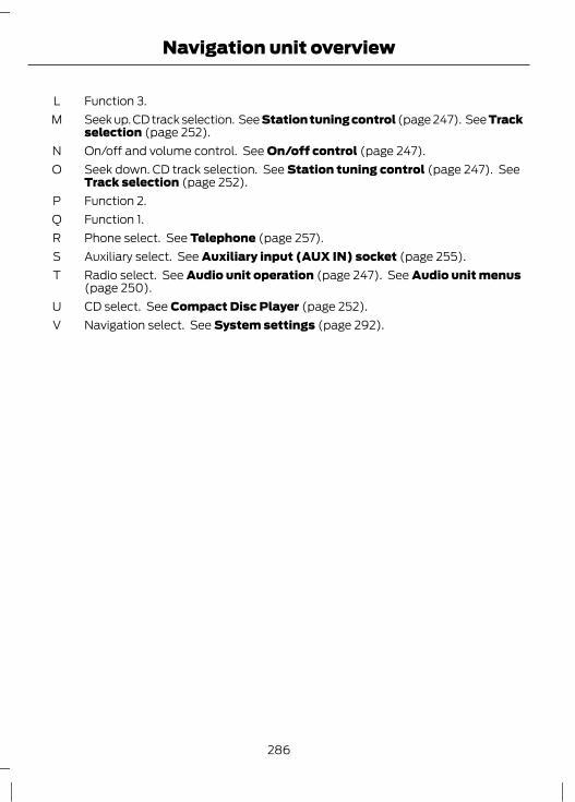
Function 3.LSeek up. CD track selection. See Station tuning control (page 247). See Trackselection (page 252).
M
On/off and volume control. See On/off control (page 247).NSeek down. CD track selection. See Station tuning control (page 247). SeeTrack selection (page 252).
O
Function 2.PFunction 1.QPhone select. See Telephone (page 257).RAuxiliary select. See Auxiliary input (AUX IN) socket (page 255).SRadio select. See Audio unit operation (page 247). See Audio unit menus(page 250).
T
CD select. See Compact Disc Player (page 252).UNavigation select. See System settings (page 292).V
286
Navigation unit overview

Vehicles with Sony CD-SD navigation system
A CB FE
Y
I
G
H
J
L
KT
U
W
X
V
QS R N MOP
D
E129242
On/off control. See On/off control (page 247).ANavigation select. See System settings (page 292).BTelephone keypad and station presets. See Audio unit operation (page 247).See Audio unit menus (page 250). See Telephone (page 257).
C
CD aperture.DNavigation arrows.EMap select. See Route displays (page 296).FCD eject.GInformation.HClock. See System settings (page 292).ISeek up. CD track selection. end call. See Station tuning control (page 247).See Track selection (page 252). See Using the telephone (page 258).
J
287
Navigation unit overview

Home select. See System settings (page 292).KTraffic announcement. See Traffic Message Channel (page 297).LFunction 4.MSound select. See Sound button (page 247).NFunction 3.OOK.PFunction 2.QMenu select. See System settings (page 292).RFunction 1.SPhone select. See Telephone (page 257).TAuxiliary select. See Auxiliary input (AUX IN) socket (page 255).USeek down. CD track selection. accept call. See Station tuning control (page247). See Track selection (page 252). See Using the telephone (page 258).
V
Radio select. See Audio unit operation (page 247). See Audio unit menus(page 250).
W
CD select. See Compact Disc Player (page 252).XVolume control.Y
LOADING THE NAVIGATIONDATALoading the navigation data
E129900
1. Load the navigation SD card into theaperture.
2. Press the NAV button. The road safetywarning will be shown in the display.
3. Use the up and down arrow buttons toselect the required feature.
4. Press the OK button to confirm yourselection.
For map updates and system upgradesplease refer to your dealer.
288
Navigation unit overview

Vehicles with mobile navigationsystem
CAUTIONUsing the system with the engine offwill drain the battery.
Note: You will be charged when sendingand receiving text messages.Note: Refer to your phone handbook for allphone functions and operation.Note: Keep the activation code (printed onthe installation guide) in a safe place.Note: Retain the activation text messagein your mobile phone inbox.
Compatibility of phones
CAUTIONAs no common agreement exists,mobile phone manufacturers are ableto implement a variety of profiles in
their Bluetooth devices. Because of this,an incompatibility can occur between thephone and hands-free system, which insome cases may significantly degrade thesystem performance. To avoid thissituation, only recommended phonesshould be used.
Please visit the websitewww.ford-mobile-connectivity.com forfull details.
Installing the micro SD card
1
2
E114212
1. Remove the micro SD card from theadaptor.
2. Insert the micro SD card into the mobilephone.
Activating the mobile phonenavigation systemNote: The radio must be switched on beforeconnecting the mobile phone to the in-carGPS receiver.Note: The Ford Mobile Navigation must beinstalled and activated on your mobilephone.Note: It is possible to activate up to amaximum of three phones.Note: Detailed instructions are availableon the micro SD card and atwww.ford-mobile-connectivity.com.To connect the device to the system followthe same procedure as for Bluetooth handsfree phones. See Bluetooth setup (page257).1. Switch the radio on.
289
Navigation Quick start

E114213
2. Switch your mobile phone on and startthe "Ford Mobile Navigation".
3. Choose "Select Destination".4. Choose "Enter Address".5. Change route options if necessary and
start the route guidance.6. The vehicle display will show the turn
information. Voice instructions areheard via the vehicle speakers.
Note: Your mobile phone will display yourcurrent position.7. You are able to exit the application and
continue your route guidance afterrestarting the application.
Vehicles with CD-SD navigationsystem or Sony CD-SD navigationsystemThe system has a large range of features,yet is easy and intuitive to use. Routeguidance is shown on the display screen.The screen provides full information foroperating the system through the use ofmenus, text screens and map displays.Screen selections are made by scrollingthrough the menus using the up, down, leftand right arrow buttons and pressing theOK button to activate the desired setting.
Basic operation1. Press either the NAV or MENU button
to enter the menu structure.2. Use the up, down, left and right arrow
buttons and scroll through the variousselection lists.
3. Press the OK button to activate yourselection.
Selection listsVarious screens are presented which offera selection list of available options.1. Select the option you require, or if it is
not shown on the screen use the upand down arrow buttons to view theremainder of the selection list.
2. Press the OK button to confirm yourselection.
Alphanumeric keypad entryWhen it is necessary to enter an address,a keypad will appear prompting you toenter a postcode, city, or street.1. Use the up, down, left and right arrow
buttons to select the letter or numberthat you require.
Note: As you spell the entry the results willappear in the display.Note: The system will limit your entries toonly those characters which spell a validentry.2. Press the OK button to activate your
selection.
Route setting exampleNavigation main screen• To select the navigation system, press
the NAV button. The road safetycaution will be displayed. To use thesystem, read the caution and press theOK button.
Destination input screen• Use the up and down arrow buttons
and scroll to Destination input.• Press the OK button to activate your
selection.Note: A list with several options is shown.
290
Navigation Quick start

• Starting from the top, select thecountry followed by either thepostcode if available or city and streetname.
• Use the alphanumeric keypad andselection lists to select your addressdetails.
• Once sufficient information has beenentered, scroll to Start guidance andpress the OK button to activate yourselection.
Note: If you only need to navigate to a citycentre for example, full address details arenot required.• The route is now calculated and the
screen returns to the main navigationscreen with instructions on how toproceed.
• Follow the screen information andvoice prompts to reach yourdestination.
291
Navigation Quick start
Most of the important settings for yournavigation unit can be accessed via theMENU or NAV button. The followingsection describes the various options andhow to use them.For menu structures: See InformationDisplays (page 78).
Menu structure - Information andentertainment display - Vehicleswith navigation systemRouteThis feature allows you to customise theroute to your specific journey requirements(for example continue route guidance,block specific sections of your route orselect specific sections of a route).
Destination inputThis feature allows you to enter yourdestination details (for example enter citynames, enter street names or pick a placefrom a map).
TrafficThis feature allows you to customise howyou receive traffic information (forexample review and sort traffic messages,review your route or block parts of yourroute).
Home addressThis feature allows you to start the routeguidance to your home address or changethe details of your home address.Note: On Vehicles with a Sony CD-SDnavigation system, press the HOME buttonand the system will automatically startroute guidance to the listed home address.
Last destinationsThis feature allows quick access to ahistory of previous destinations entered inthe system. A detailed display will showthe complete stored information includingan overview map. Select the requiredrepeat destination from the list.
FavouritesThis feature allows you to customize apersonal destination address book andassign user defined names to addressesand locations. A detailed display will showthe complete stored information includingan overview map. Select the requiredrepeat destination from the list.
Points of interestThis feature allows you to customise theroute to your specific journey requirements(for example select a museum on route ora specific point of interest near yourdestination).
Tour planningThis feature allows you to enter a numberof different destinations and select theorder in which you wish to visit them. Youcan also modify an existing tour or recall aprevious tour. The system willautomatically calculate and display yourchosen journey.
Store positionThis feature allows you to store and nameyour current position.
Route optionsThis feature allows you to customise theroute to your specific journey requirements(for example select the fastest or mosteconomical route or select a route that willavoid tunnels, seasonal roads and tollroads).
292
System settings
Special functionsThis feature allows you to select GPS andsystem information or a demonstration ofthe system functionality.
Map displayThis feature allows you to change the waythe map screen is displayed (for exampleclean 2D and clean 3D view) and tocustomise display information for yourjourney (for example time to arrival andlane guidance).
Assistance optionsThis feature allows you to customisedisplay information for your journey (forexample signs, lanes and speed limits).
Personal dataThis feature allows you to edit and deletepersonal data (for example your homeaddress).
Reset all settingsThis feature allows you to reset thenavigation settings.
Menu structure - Information andentertainment display - AllvehiclesAudio settingsAdaptive volumeThis feature allows you to adjust thevolume level to compensate for engine androad speed noise. You can turn this on andoff.
SoundThis feature allows you to adjust the soundsettings (for example bass and treble).
Nav audio mixingThis feature allows you to adjust thevolume mix between the navigation voiceoutput and audio source.
DSP settingsThis feature allows you to customisespeaker output relevant to seat positions.
DSP equaliserThis feature allows you to select the musiccategory that most suits your listeningpreference. The audio output will changeto enhance the particular style of musicchosen.
NewsThis feature allows you to receive newsbulletins from stations on the FMwaveband or radio data system (RDS) andenhanced other network (EON) linkedstations, in the same way as trafficinformation is provided. You can turn thison and off.
Alternative frequenciesThis feature will search for and switch tothe strongest station signal when movingfrom one transmission area to another.
RDS regionalThis feature controls the behaviour of AFswitching between regionally relatednetworks of a parent broadcaster.
DAB service linkThis feature allows you to select stationsthat are broadcast on the DAB channels.
BluetoothThis feature allows you to switchBluetooth on or off.
293
System settings
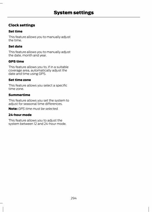
Clock settingsSet timeThis feature allows you to manually adjustthe time.
Set dateThis feature allows you to manually adjustthe date, month and year.
GPS timeThis feature allows you to, if in a suitablecoverage area, automatically adjust thedate and time using GPS.
Set time zoneThis feature allows you select a specifictime zone.
SummertimeThis feature allows you set the system toadjust for seasonal time differences.Note: GPS time must be selected.
24-hour modeThis feature allows you to adjust thesystem between 12 and 24-hour mode.
294
System settings

ROUTE OPTIONS MENUYou can set a number of options whichalter the way a route is planned.Using the up, down, left and right arrowbuttons, you can select from the list whichroad features are to be avoided or includedin the route by turning the feature on or off.
RouteEcoThis option will prioritise the mosteconomical route to the destination.
FastThis option will prioritise the fastest routeto the destination.
ShortThis option will prioritise the shortest routeto the destination..
Always askUse this feature to make sure that you arealways given the choice of route typeselection for your journey.
DriverLeisurelyThis option will prioritise the route for aleisurely driver to the destination.
NormalThis option will prioritise the route for anormal driver to the destination.
FastThis option will prioritise the route for afast driver to the destination.
Eco settingsTrailerUse this feature to change the economysettings of your journey relating to whetheror not you are towing a trailer and if so thesize of trailer being towed.
Roof boxUse this feature to change the economysettings of your journey relating to the useof a roof box.
DynamicWhen switched on, and if the unit isreceiving a valid traffic message channel(TMC) signal, the route will beautomatically updated to take intoaccount real time traffic incidents orcongestion.Note: This feature can be useful in avoidingdelays or hold ups on journeys.
MotorwayWhen switched on the system will look formotorways on your route andautomatically update your route distanceand timings.Note: This feature can be useful in avoidingdelays or hold ups on journeys.
Ferry/motorailWhen switched on the system will look forferry crossings and motorail facilities onyour route and automatically update yourroute distance and timings.
TollWhen switched on the system will look fortoll roads on your route and automaticallyupdate your route distance and timings.
295
Navigation system

Seasonal roadsWhen switched on the system will look forseasonal roads on your route andautomatically update your route distanceand timings.Note: This feature can be useful in avoidingdelays or hold ups on journeys.
Toll stickerWhen switched on the system willautomatically select toll roads and updateyour route distance and timings.
ROUTE DISPLAYSMap displayPress the MAP button for a map view.This view will show your current locationwith your vehicle in the centre shown asan arrow surrounded by a circle. The arrowwill face in the direction of travel.The information on the top line gives thename of the current road, or the next roadto take if a turn is approaching.You can change the way the map isdisplayed by altering the zoom andorientation settings. Press the relevantfunction buttons to change the map scaleand using the left and right arrow buttonszoom in or out. The current map scale isshown on the display.Map scale settings may be set between50 metres to 500 kilometres or 0.05 milesto 500 miles, with an auto setting to thefar left. The auto setting continuouslychanges the map scale according to theroad type being driven.
Junction zoomThis feature will automatically increasethe zoom on the map display at timeswhen you are required to make a turn, orperform more complex manoeuvres.Shortly after the zoom scale will return tothe previous level.Select AUTO to activate junction zoom.
Navigation displayAfter commencing a navigation route, thedefault screen is the main navigationscreen:Once an active route is underway, guidancewill be given by on-screen information andvoice prompts. Whichever audio sourceyou wish to leave the unit in, basic turn byturn and distance information will remainon the screen in the form of a graphic inset.You do not need to leave the unit on themain navigation screen when you arenavigating a route. Slightly more detailedinformation on your route may be availablevia the main navigation screen if required.
WARNINGDo not rely on the screen promptswhen navigating. Always listen to thenavigation voice and take care not
be distracted from the road ahead.
296
Navigation system

PRINCIPLE OF OPERATIONTraffic message channel (TMC) stationsare broadcast on the FM waveband. TMCis a feature that receives traffic alertswhich can be used to plan alternativeroutes and avoid hold ups.
USING TMCPress the TA or TRAFFIC button to showthe traffic menu page.
Traffic announcementTraffic announcement (TA) can be turnedon or off via this menu. If switched on a TAindicator is shown in the informationborder of the status bar.Stations which broadcast on the FMwaveband and carry traffic programme(TP) information are identified by TPshown in the screen display. With TAswitched on the unit will respond to theseannouncements and interrupt musicplayback. After the announcement hasended music playback will resume.
Ending traffic announcementsThe unit will return to normal operation atthe end of each traffic announcement. Toend the announcement prematurely, pressthe TA, TRAFFIC, RADIO or CD buttonduring the announcement.
Using TMC messagesSelect the required item to display a list ofTMC messages. See GeneralInformation (page 78). This is only anoverview display which gives very basicinformation. Select the message yourequire further information on and anotherscreen will be displayed giving full messagedetails on incident location etc.
You may either select a view which showsmessages only affecting your programmedroute, or a view which shows all messagesreceived. Press function button 1 to changethe view.
Hazard spot warning (dependingon country)Note: The availability of this feature willvary from country to country.The system supports a hazard spotwarning feature which informs you withvisible and audible feedback abouthazardous traffic areas. The system is offby default. You can switch the system onand off using the information display. SeeInformation Displays (page 78).
297
Traffic Message Channel

The road network is constantly changingdue to new roads, changes in roadclassification, etc. Therefore, it is notalways possible to exactly match the mapdata in the system to the current roadnetwork.Map information is regularly updated, butall areas are not necessarily covered to thesame level of detail. Some roads, inparticular private roads, may not beincluded on the database. To help withaccuracy, always use the latest versionnavigation disc. Your dealer will be able toprovide this.
298
Map updates

TYPE APPROVALSFCC/INDUSTRY CANADA NOTICEThis device complies with Part 15 of theFCC Rules. Operation is subject to thefollowing two conditions: (1) this devicemay not cause harmful interference, and(2) this device must accept anyinterference received, includinginterference that may cause undesiredoperation.FCC ID: WJLRX-42IC: 7847A-RX42Changes or modifications to your devicenot expressly approved by the partyresponsible for compliance can void theuser's authority to operate the equipment.
RX-42 - declaration of conformityWe, the party responsible for compliance,declare under our sole responsibility thatthe Handset Integration product RX-42 isin conformity with the provisions of thefollowing Council Directive: 1999/5/EC. Acopy of the Declaration of Conformity canbe found at:
www.novero.com/declaration_of_conformityThe Bluetooth word mark and logos areowned by the Bluetooth SIG, Inc. and anyuse of such marks by Ford Motor Companyis under license. Other trademarks andtrade names are those of their respectiveowners.
TYPE APPROVALSiPod is a trademark of Apple Inc.
TYPE APPROVALS
E114214
© 2008 NAVTEQ B.V. All rights reserved.
299
Appendices

E114220
TYPE APPROVALS
E97713
E97714
SD Logo is a trademark.
TYPE APPROVALSLaser sensor
E132582
300
Appendices

WARNINGSInvisible laser radiation. Do not viewdirectly with optical instruments(magnifiers). Class 1M laser product.
WARNINGSIEC 60825-1: 1993 + A2:2001.Complies with FDA performancestandards for laser products except
for deviation pursuant to Laser Notice No.50, dated July 26th, 2001.
SpecificationItem
45mWMax average power
33nsPulse duration
905nmWavelength
TYPE APPROVALSEU DeclarationHereby, Valeo declares that this shortrange device is in compliance with theessential requirements and other relevantprovisions of Directive 1999/5/EC.
Certificate for United ArabEmirates
E125209
TYPE APPROVALSThe navigation software is based in parton the work of the FreeType team © 2006
TYPE APPROVALSThe navigation software is based in parton the work of the independent JPEGGroup.
ELECTROMAGNETICCOMPATIBILITY
WARNINGSYour vehicle has been tested andcertified to legislations relating toelectromagnetic compatibility
(72/245/EEC, UN ECE Regulation 10 orother applicable local requirements). It isyour responsibility to ensure that anyequipment you have fitted complies withapplicable local legislations. Have anyequipment fitted by properly trainedtechnicians.
The RF (radio frequency) transmitterequipment (e.g. cellular telephones,amateur radio transmitters etc.) may
only be fitted to your vehicle if they complywith the parameters shown in the tablebelow. There are no special provisions orconditions for installations or use.
301
Appendices

WARNINGSDo not mount any transceiver,microphones, speakers, or any otheritem in the deployment path of the
airbag system.
WARNINGSDo not fasten antenna cables tooriginal vehicle wiring, fuel pipes andbrake pipes.Keep antenna and power cables atleast 10 centimetres (4 inches) fromany electronic modules and airbags.
E85998
1 2 3 4
Antenna PositionsMaximum output power Watt (PeakRMS)
Frequency BandMHz
3, 450 W1 – 30
1, 2, 350 W30 – 54
1, 2, 350 W68 – 87.5
1, 2, 350 W142 – 176
1, 2, 350 W380 – 512
1, 2, 310 W806 – 940
1, 2, 310 W1200 – 1400
1, 2, 310 W1710 – 1885
1, 2, 310 W1885 – 2025
302
Appendices

Note: After the installation of RFtransmitters, check for disturbances fromand to all electrical equipment in thevehicle, both in the standby and transmitmodes.Check all electrical equipment:• with the ignition ON• with the engine running• during a road test at various speeds.Check that electromagnetic fieldsgenerated inside the vehicle cabin by thetransmitter installed do not exceedapplicable human exposure requirements.
303
Appendices

304

AA/C
See: Climate Control..........................................98About This Manual...........................................7
Protecting the Environment................................7ABS
See: Brakes............................................................137ABS driving hints
See: Hints on Driving With Anti-LockBrakes.................................................................137
ACCSee: Adaptive cruise control (ACC).............154
AccessoriesSee: Replacement Parts
Recommendation..............................................9See: Using Adaptive Cruise Control.............156
Active City Stop............................................168Principle of Operation......................................168
Active Park Assist.........................................149Principle of Operation.......................................149
Adaptive cruise control (ACC)................154Principle of Operation.......................................154
Adaptive cruise control (ACC)See: Using Adaptive Cruise Control.............156
Adjusting the Headlamps - VehiclesWith: Adaptive Front Lighting/XenonHeadlamps....................................................53
Adjusting the Steering Wheel....................43Air Conditioning
See: Climate Control..........................................98Air Vents............................................................98
Centre air vents.....................................................98Side air vent...........................................................99
Alarm...................................................................41Principle of Operation.........................................41
Alternative frequencies.............................250Appendices....................................................299Arming the alarm...........................................42Arming the engine immobiliser................40At a Glance........................................................10
Front exterior overview.......................................10Instrument panel overview................................12Rear exterior overview.........................................15Vehicle interior overview......................................11
Audible Warnings and Indicators.............76Automatic transmission....................................76Door open................................................................76Frost...........................................................................76Key outside car......................................................76Lights on..................................................................76Low fuel....................................................................77Seat belt reminder................................................77Switching the chimes on and off....................76
Audio Control...................................................43Type 1........................................................................43Type 2.......................................................................44
Audio introduction......................................239Audio System Security..............................246Audio troubleshooting...............................256Audio Troubleshooting..............................256Audio unit commands...............................262
Auxiliary input.....................................................266CD Player..............................................................262External devices - iPod....................................268External devices - USB....................................266Radio......................................................................263
Audio unit menus........................................250Audio unit operation...................................247Audio unit overview....................................240Auto-Dimming Mirror...................................68Autolamps........................................................50Automatic Climate Control.......................101
Air distribution.....................................................103Blower.....................................................................102Cooling the interior quickly.............................103Mono mode..........................................................102Recirculated air...................................................103Setting the temperature..................................102Switching off the automatic climate
control...............................................................103Switching the air conditioning on and
off........................................................................103To switch mono mode back on.....................102To switch mono mode off...............................102Windscreen defrosting and
demisting..........................................................103Automatic Main Beam Control.................50
Activating the system..........................................51Manually overriding the system......................52Setting the system sensitivity..........................51
305
Index
Automatic Transmission............................134Emergency park position release
lever....................................................................136Hints on driving with an automatic
transmission....................................................135Selector lever positions....................................134Sport mode and manual shifting.................135
Automatic volume control.......................250Autostore control........................................248Autowipers.......................................................45Auxiliary Heater............................................106
Diesel auxiliary heater (depending oncountry)............................................................108
Fuel operated heater (depending oncountry)............................................................108
Parking heater.....................................................106Auxiliary input (AUX IN) socket..............255Auxiliary Input Socket...................................117Auxiliary Power Points.................................116
BBattery connection points.........................216Blind Spot Monitor........................................68
Blind spot information system (BLIS).........68Detection errors....................................................69System detection and alerts...........................68Turning the system on and off........................69Using the system.................................................68
Bluetooth setup............................................257Handling of phones...........................................257Requirements for Bluetooth
connection.......................................................257Bonnet Lock
See: Opening and Closing the Bonnet.......196Booster cables
See: Jump-Starting the Vehicle.....................215Booster Seats...................................................21
Booster cushion (Group 3)................................21Booster seat (Group 2).......................................21
Brake and Clutch Fluid Check................209Brakes................................................................137
Principle of Operation.......................................137Bulb changing
See: Changing a Bulb..........................................57Bulb Specification Chart.............................64
CCapacities and Specifications................234
Technical Specifications.................................234Cargo Nets........................................................171
Cargo net................................................................172Luggage retention net........................................171
Car WashSee: Cleaning the Exterior................................213
Catalytic Converter......................................129Driving with a catalytic converter.................129
Changing a Bulb..............................................57Approach lamp.....................................................59Central high mounted brake lamp................63Front fog lamps....................................................60Headlamp................................................................57Interior lamps.........................................................63Luggage compartment lamp, footwell lamp
and tailgate lamp............................................63Number plate lamp.............................................63Rear lamps - 4 door.............................................61Rear lamps - 5 door............................................60Side repeater.........................................................59
Changing a Fuse...........................................185Changing a Road Wheel.............................217
Assembling the wheel brace..........................219Installing a road wheel....................................220Jacking and lifting points.................................218Locking wheel nuts.............................................217Removing a road wheel..................................220Removing the wheel trim................................219Vehicle jack............................................................217Vehicles with a spare wheel............................217
Changing the Door Edge Protector.........39Changing the remote control
battery.............................................................30Remote control with a folding key
blade....................................................................30Remote control without a folding key
blade.....................................................................31Changing the Vehicle Battery..................216Changing the Wiper Blades........................47
Rear window wiper blade.................................48Windscreen wiper blades..................................47
Checking the Wiper Blades.........................47Childminder Mirror.........................................117Child Safety........................................................17
306
Index

Child Safety Locks..........................................23Electric child safety locks..................................23Manual child safety locks..................................23
Child Seat Positioning...................................18Child Seats.........................................................17
Child restraints for different massgroups...................................................................17
Cigar Lighter....................................................116Cleaning the Exterior...................................213
Body paintwork preservation.........................214Cleaning the alloy wheels................................213Cleaning the chrome trim................................213Cleaning the headlamps..................................213Cleaning the rear window................................213
Cleaning the Interior....................................214Instrument cluster screens, LCD screens,
radio screens...................................................214Rear windows.......................................................214Seat belts...............................................................214
Climate Control..............................................98Principle of Operation........................................98
Climate control commands.....................274Climate...................................................................274
Clock...................................................................116Coded keys.......................................................40Cold Weather Precautions........................182Compact disc playback.............................252Compact Disc Player..................................252Compact disc track scanning..................253
Type 1......................................................................253Type 2 and 3.........................................................253
Connecting an external device...............278Connection...........................................................278
Connecting an external device - VehiclesWith: Bluetooth.........................................278Connecting a Bluetooth audio device........278
Connectivity....................................................277General Information..........................................277
Convenience features..................................116Coolant Check
See: Engine Coolant Check...........................208Cornering Lamps............................................54Cruise Control................................................152
Principle of Operation.......................................152Cruise control
See: Using Cruise Control................................152Cup Holders......................................................117
Rear seat armrest.................................................117
DDiesel Particulate Filter...............................123
Regeneration........................................................123Digital signal processing (DSP).............250
Changing the DSP settings............................250DSP equaliser.....................................................250DSP occupancy..................................................250
Direction Indicators.......................................54Disabling the passenger airbag................28
Disabling the passenger airbag......................29Enabling the passenger airbag.......................29Fitting the passenger airbag deactivation
switch..................................................................28Disarming the alarm.....................................42
Vehicles with keyless entry...............................42Vehicles without keyless entry........................42
Disarming the engine immobiliser..........40Dog Guard........................................................172
Installing behind the front seats....................172Installing behind the rear seats.....................173
Door Edge Protection...................................39Principle of Operation........................................39
DPFSee: Diesel Particulate Filter...........................123
Driver Alert......................................................160Principle of Operation......................................160
Driving Hints...................................................182Driving Through Water................................182
Driving through water .......................................182
EEco Mode..........................................................127
Principle of Operation........................................127Electric exterior mirrors................................67
Electric folding mirrors........................................67Mirror tilting positions.........................................67
Electric sunroof.............................................104Opening and closing the sunroof.................105Opening and closing the sunroof
automatically..................................................105Sunroof anti-trap protection.........................105Sunroof relearning.............................................106Sunroof safety mode........................................106Tilting the sunroof..............................................105
Electromagnetic compatibility................301Ending compact disc playback..............254
307
Index
Engine Block Heater....................................124Engine Coolant Check...............................208
Checking the coolant level............................208Topping up...........................................................208
Engine immobiliser.......................................40Principle of Operation........................................40
Engine Oil Check..........................................207Checking the oil level........................................207Topping up...........................................................208
Engine Oil Dipstick - 1.0LEcoBoost.....................................................206
Engine Oil Dipstick - 1.6L Duratec-16V(Sigma).......................................................206
Engine Oil Dipstick - 1.6L Duratorq-TDCi(DV) Diesel/2.0L Duratorq-TDCi (DW)Diesel.............................................................207
Engine Oil Dipstick - 1.6L EcoBoost SCTi(Sigma).......................................................206
Engine Oil Dipstick - 2.0L Duratec-HE(MI4)..............................................................207
Engine Oil Dipstick - 2.0L EcoBoost SCTi(MI4).............................................................206
Exterior Mirrors................................................66Manual folding mirrors.......................................66
FFastening the seat belts..............................26Fast forward/reverse..................................252First Aid Kit......................................................183Floor Mats........................................................118Fog Lamps - Front
See: Front Fog Lamps.........................................52Fog Lamps - Rear
See: Rear Fog Lamps..........................................52Forward alert function................................158
Adjusting the warning sensitivity.................158Switching the system on and off..................158
Front Fog Lamps............................................52Fuel and Refuelling......................................128
Technical Specifications..................................132Fuel Burning Heater
See: Auxiliary Heater.........................................106Fuel Consumption.........................................131Fuel Consumption
See: Technical Specifications........................132Fuel filler flap.................................................129
Refuelling with a fuel can.................................131
Fuel Quality - Diesel....................................128Long-term storage.............................................129
Fuel Quality - E85........................................128Long-term storage.............................................128
Fuel Quality - Petrol....................................128Fuse Box Locations.....................................184
Engine compartment fuse box.....................184Load compartment fuse box.........................184Passenger compartment fuse box..............184
Fuses.................................................................184Fuse Specification Chart...........................186
Engine compartment fuse box.....................186Load compartment fuse box..........................191Passenger compartment fuse box..............189
GGauges.................................................................71
Engine coolant temperature gauge...............72Fuel gauge...............................................................73Oil pressure gauge................................................73Oil temperature gauge........................................73Turbocharger boost gauge................................73
GearboxSee: Transmission..............................................134
General Information on RadioFrequencies...................................................30
Glasses Holder................................................117Global Opening and Closing.......................37
Global closing........................................................37Global opening......................................................37
HHandbrake
See: Parking Brake..............................................137Hazard Warning Flashers............................53Headlamp adjustment
See: Adjusting the Headlamps - Vehicles With:Adaptive Front Lighting/XenonHeadlamps........................................................53
Headlamp Levelling......................................53Recommended headlamp levelling switch
positions.............................................................53Headlamp Washers.......................................47Head Restraints.............................................110
Adjusting the head restraint............................110Removing the head restraints..........................111
308
Index

Heated Seats...................................................114Heated Windows and Mirrors..................104
Heated exterior mirrors....................................104Heated windows................................................104
HeatingSee: Climate Control..........................................98
Hill launch assist (HLA)See: Using hill start assist...............................140
Hill Start Assist.............................................140Principle of Operation......................................140
Hints on Driving With Anti-LockBrakes.............................................................137
HLASee: Hill Start Assist..........................................140See: Using hill start assist...............................140
IIgnition Switch................................................119Immobiliser
See: Engine immobiliser....................................40Important audio information..................239
Audio unit labels................................................239Disc labels............................................................239
Information Displays.....................................78General Information............................................78
Information Messages.................................86Active City Stop.....................................................87Airbag........................................................................87Alarm.........................................................................87Automatic main beam control........................87Battery and charging system..........................88Blind spot monitor..............................................88Child power lock...................................................88Climate control.....................................................88Cruise control and Adaptive cruise control
(ACC)...................................................................89Doors open.............................................................89Driver alert..............................................................89Engine immobiliser.............................................90Hill start assist......................................................90Keyless entry.........................................................90Lane keeping aid...................................................91Lighting.....................................................................91Maintenance..........................................................92Message indicator...............................................86Occupant protection..........................................92Parking aid..............................................................92Parking brake.........................................................93Power steering......................................................93Stability control (ESP).......................................93Starting the engine..............................................94Start-stop...............................................................95Transmission.........................................................96Tyre pressure monitoring system...................97
Instrument Cluster..........................................71Instrument Lighting Dimmer.....................116Interior Lamps.................................................55
Ambient lighting...................................................55Interior lighting......................................................55
Introduction.........................................................7iPod connection
See: Connecting an external device...........278See: Connecting an external device - Vehicles
With: Bluetooth..............................................278iPod
See: Using an iPod............................................280ISOFIX Anchor Points...................................22
Attaching a child seat with toptethers..................................................................22
Top tether anchor points - 4 door..................22Top tether anchor points - 5-door and
estate...................................................................22
309
Index
JJump starting
See: Jump-Starting the Vehicle.....................215Jump-Starting the Vehicle........................215
To connect the booster cables......................215To start the engine.............................................216
KKeyless Entry....................................................35
Disabled keys.........................................................36General information............................................35Locking and unlocking the doors with the
key blade.............................................................37Locking the vehicle..............................................35Passive key..............................................................35Unlocking the vehicle.........................................36
Keyless Starting..............................................121Failure to start......................................................122Ignition on..............................................................122Starting a diesel engine....................................122Starting with automatic transmission........122Starting with manual transmission.............122Stopping the engine when the vehicle is
moving...............................................................123Stopping the engine with the vehicle
stationary..........................................................123Keys and Remote Controls.........................30
LLane Departure Warning...........................162
Principle of Operation.......................................162Lane Keeping Aid..........................................164
Principle of Operation.......................................164Lighting Control..............................................49
Headlamp flasher................................................49Home safe lighting..............................................50Lighting control positions.................................49Main and dipped beam......................................49Parking lamps........................................................49
Lighting..............................................................49Load Carriers
See: Roof Racks and Load Carriers..............174Load Carrying.................................................170
General Information..........................................170
Loading the navigation data...................288Loading the navigation data.........................288
Locking and Unlocking.................................33Double locking.......................................................33Locking.....................................................................33Locking and unlocking confirmation............34Locking and unlocking the doors from
inside....................................................................34Locking the doors individually with the
key.........................................................................34Luggage compartment lid................................34Unlocking.................................................................33
Locks...................................................................33Luggage Anchor Points..............................170Luggage Covers.............................................170
MMaintenance..................................................196
General Information..........................................196Technical Specifications................................209
Manual Climate Control..............................99Air conditioning...................................................100Air distribution control.......................................99Blower....................................................................100Heating the interior quickly............................100Recirculated air...................................................100Ventilation............................................................100
Manual Seats.................................................109Adjusting the angle of the seatback............110Adjusting the height of the driver’s
seat......................................................................110Adjusting the lumbar support........................110Moving the seats backwards and
forwards............................................................109Manual Transmission..................................134
Selecting reverse gear.......................................134Map updates.................................................298Message Centre
See: Information Displays.................................78Mirrors
See: Heated Windows and Mirrors..............104See: Windows and Mirrors................................65
MP3 connectionSee: Connecting an external device...........278See: Connecting an external device - Vehicles
With: Bluetooth..............................................278
310
Index
MP3 display options...................................253CD text display options...................................254
MP3 file playback........................................253Playing a multi session disc...........................253
NNavigation introduction............................282
General Information.........................................282Navigation Quick start...............................289
Vehicles with CD-SD navigation system orSony CD-SD navigation system.............290
Vehicles with mobile navigationsystem..............................................................289
Navigation system......................................295Navigation unit overview..........................284
Vehicles with CD-SD navigationsystem..............................................................285
Vehicles with Sony CD-SD navigationsystem...............................................................287
News broadcasts.........................................250
OOccupant protection.....................................25
Principle of Operation.........................................25Oil Check
See: Engine Oil Check......................................207On/off control................................................247Opening and Closing the Bonnet...........196
Closing the bonnet.............................................197Opening the bonnet..........................................196
PParking Aids....................................................142
Principle of Operation.......................................142Parking Aid - Vehicles With: Front and
Rear Parking Aid.........................................143Manoeuvring with the parking aid...............144Switching the parking aid on and off..........143
Parking Aid - Vehicles With: Rear ParkingAid....................................................................142
Parking Brake..................................................137
Personalised Settings..................................85Chime deactivation.............................................86Language setting.................................................85Measure units........................................................86Temperature units...............................................86
Power Door LocksSee: Locking and Unlocking.............................33
Power Seats - Vehicles With: 6-WayPower Seats..................................................112
Power Seats - Vehicles With: 8-WayPower Seats..................................................112Adjust the length of the seat cushion..........113
Power Windows.............................................65Anti-trap function................................................65Driver's door switches........................................65Global opening and closing.............................65Opening and closing the windows
automatically....................................................65Resetting the memory of the electric
windows.............................................................66Safety switch for rear windows......................65
Programming the remote control............30Programming a new remote control............30Reprogramming the unlocking
function...............................................................30
RRear Fog Lamps..............................................52Rear Seats........................................................113
Folding the rear seatbacks forwards............113Folding the seatbacks up.................................114Folding the seat cushions and the rear
seatbacks forwards.......................................114Rear view camera.........................................146
Principle of Operation.......................................146Rear View Camera.......................................146
Activating the rear view camera...................146Deactivating the rear view camera..............148Using the display.................................................147Vehicles with parking aid.................................148
Rear Window Wiper and Washers..........46Intermittent wipe.................................................46Rear window washer...........................................47Reverse gear wipe................................................47
Refuelling - E85..............................................131Refuelling..........................................................131Regional mode (REG).................................251
311
Index

Remote control batterySee: Changing the remote control
battery.................................................................30Remote control programming
See: Programming the remote control........30Removing a Headlamp................................56Repairing Minor Paint Damage................214Repeat compact disc tracks....................252
Type 1......................................................................252Type 2 and 3.........................................................252
Replacement PartsRecommendation.........................................9Collision Repairs......................................................9Scheduled Maintenance and Mechanical
Repairs...................................................................9Warranty on Replacement Parts......................9
Retractable tow ball....................................176Driving with a trailer...........................................178Fault conditions...................................................178Maintenance.........................................................178Releasing the tow ball arm..............................177Swivelling the tow ball arm in........................178Swivelling the tow ball arm out.....................177
Road Safety...................................................282Safety information............................................283
Roadside Emergencies...............................183Roof Racks and Load Carriers..................174
Installing the crossbars.....................................174Roof rack................................................................174
Route displays..............................................296Junction zoom....................................................296Map display.........................................................296Navigation display.............................................296
Route options menu...................................295Driver......................................................................295Dynamic................................................................295Eco settings.........................................................295Ferry/motorail.....................................................295Motorway..............................................................295Route......................................................................295Seasonal roads..................................................296Toll...........................................................................295Toll sticker............................................................296
Running-In.......................................................182Brakes and clutch...............................................182Engine.....................................................................182Tyres........................................................................182
SSafety Precautions.......................................128Satellite Navigation Unit Holder..............118
Adjusting the holder...........................................118Seat belt height adjustment......................27Seat belt reminder..........................................27
Deactivating the seat belt reminder.............28Rear seat belt reminder.....................................28
Seat beltsSee: Fastening the seat belts..........................26
Seats.................................................................109Security code................................................246Shuffle/random............................................252
Type 1......................................................................252Type 2 and 3.........................................................252
Sitting in the Correct Position.................109Snow Chains
See: Using Snow Chains.................................225See: Using Snow Chains - 2.0L EcoBoost SCTi
(MI4)..................................................................226Sound button.................................................247Speed Control
See: Cruise Control.............................................152Speed Limiter.................................................159
Principle of Operation.......................................159Stability Control............................................138
Principle of Operation.......................................138Starter Switch
See: Ignition Switch............................................119Starting a Diesel Engine..............................121
Cold or hot engine...............................................121Starting and Stopping the Engine...........119
General Information...........................................119Starting a Petrol Engine - E85.................120
Starting at low ambient temperatures................................................................................121
Starting a Petrol Engine.............................120Cold or hot engine..............................................120Engine idle speed after starting....................120Flooded engine....................................................120
Start-Stop.......................................................125Principle of Operation.......................................125
Station preset buttons..............................248
312
Index

Station tuning control................................247DAB service linking............................................247Manual tuning.....................................................247Scan tuning..........................................................248Seek tuning...........................................................247
Steering Wheel Lock....................................119Vehicles with keyless starting.........................119Vehicles without keyless starting..................119
Steering Wheel...............................................43Sunroof
See: Electric sunroof.........................................104Switching Off the Engine...........................124
Vehicles with a turbocharger.........................124Symbols Glossary.............................................7System settings............................................292
Audio settings.....................................................293Clock settings.....................................................294Menu structure - Information and
entertainment display - Allvehicles.............................................................293
Menu structure - Information andentertainment display - Vehicles withnavigation system.........................................292
TTechnical Specifications
See: Capacities and Specifications............234Telephone commands..............................269
Create a phonebook..........................................272Main settings........................................................273Phone.....................................................................269Phone functions.................................................270
Telephone controls.....................................258Remote control..................................................258
Telephone setup...........................................257Bond another Bluetooth phone...................258Making a phone an active phone................258Phonebook...........................................................257Phonebook categories.....................................258
Telephone.......................................................257General Information..........................................257
TelephoneSee: Using the telephone...............................258
Temporary Mobility Kit................................221Checking the tyre pressure.............................224General information...........................................221Inflating the tyre.................................................222Using the tyre repair kit....................................222
Tow Ball............................................................179Driving with a trailer..........................................180Driving without a trailer.....................................181Inserting the tow ball arm..............................180Maintenance.........................................................181Removing the tow ball arm.............................181Unlocking the tow ball arm
mechanism......................................................179Towing a Trailer - 2.0L EcoBoost SCTi
(MI4)...............................................................176Towing a Trailer..............................................176
Steep gradients...................................................176Towing Points................................................194
Installing the towing eye..................................194Towing eye location...........................................194
Towing the Vehicle on FourWheels..........................................................194All vehicles............................................................194Vehicles with automatic
transmission....................................................195Towing...............................................................176Track selection..............................................252
Type 2 and 3.........................................................252Traffic information control.......................248
Activating traffic announcements..............248Ending traffic announcements.....................249Traffic announcement volume.....................249
Traffic Message Channel..........................297Principle of Operation......................................297
Traffic Sign Recognition.............................166Principle of Operation......................................166
Transmission..................................................134Trip Computer.................................................85
Average fuel consumption...............................85Average speed.......................................................85Distance to empty...............................................85Instantaneous fuel consumption..................85Odometer................................................................85Outside air temperature....................................85Resetting the trip computer.............................85Trip Odometer.......................................................85
313
Index

Type approvals.............................................299Certificate for United Arab Emirates...........301EU Declaration.....................................................301FCC/INDUSTRY CANADA NOTICE.............299Laser sensor........................................................300RX-42 - declaration of conformity..............299
Tyre Care.........................................................225Tyre Pressure Monitoring System..........226
System reset........................................................227Tyre Pressures
See: Technical Specifications........................227Tyre Repair Kit
See: Temporary Mobility Kit............................221Tyres
See: Wheels and Tyres......................................217
UUnder Bonnet Overview - 1.0L
EcoBoost......................................................198Under Bonnet Overview - 1.6L
Duratec-16V (Sigma)..............................199Under Bonnet Overview - 1.6L
Duratorq-TDCi (DV) Diesel..................204Under Bonnet Overview - 1.6L EcoBoost
SCTi (Sigma).............................................200Under Bonnet Overview - 2.0L
Duratec-HE (MI4).....................................202Under Bonnet Overview - 2.0L
Duratorq-TDCi (DW) Diesel.................205Under Bonnet Overview - 2.0L EcoBoost
SCTi (MI4)....................................................201USB Port............................................................117USB
See: Using a USB device.................................279Using Active City Stop - 2.0L EcoBoost
SCTi (MI4)...................................................169Switching the system on and off.................169
Using Active City Stop................................168Switching the system on and off.................169
Using active park assist.............................149
Using Adaptive Cruise Control................156Automatic deactivation....................................157Changing the set speed...................................156Setting a speed...................................................156Setting the vehicle gap.....................................156Switching the system off.................................157Switching the system on.................................156Temporarily deactivating the system..........157
Using an iPod................................................280Audio control........................................................281Operation.............................................................280
Using a USB device.....................................279Audio control......................................................280Operation..............................................................279
Using Cruise Control....................................152Cancelling the set speed.................................152Changing the set speed...................................152Resuming the set speed..................................153Setting a speed....................................................152Switching cruise control off............................153Switching cruise control on.............................152
Using driver alert..........................................160Resetting the system.........................................161Switching the system on and off.................160System display.....................................................161System warnings................................................160
Using Eco mode.............................................127Resetting Eco mode...........................................127
Using hill start assist...................................140Activating the system.......................................140Deactivating the system..................................140Vehicles with manual transmission
only.....................................................................140Using lane departure warning.................162
Setting the steering wheel vibrationlevel.....................................................................163
Setting the system sensitivity........................163Switching the system on and off..................162System warnings................................................163
Using seat belts during pregnancy..........28Using Snow Chains - 2.0L EcoBoost SCTi
(MI4)..............................................................226Vehicles with stability control (ESP).........226
Using Snow Chains.....................................225Vehicles with stability control (ESP)..........225
314
Index

Using Stability Control - 2.0L EcoBoostSCTi (MI4)....................................................139Switching sport mode on................................139Switching the system off.................................139
Using Stability Control...............................138Using start-stop............................................125
To re-start the engine.......................................126To stop the engine..............................................125
Using the lane keeping aid........................164Switching the system on and off.................164System warnings................................................165
Using the speed limiter..............................159Intentionally exceeding the set speed
limit.....................................................................159Setting the speed limit.....................................159Switching the system on and off..................159System warnings................................................159
Using the telephone...................................258Changing the active phone...........................260Debonding a bonded phone.........................260Making a call.......................................................259Muting the microphone..................................260Receiving an incoming call............................260Receiving a second incoming call...............260
Using TMC......................................................297Ending traffic announcements.....................297Hazard spot warning (depending on
country)............................................................297Traffic announcement.....................................297Using TMC messages.......................................297
Using traffic sign recognition...................166Setting the system speed warning..............166Switching the system on and off.................166System display....................................................166
Using voice control.......................................261Name tag..............................................................262System operation...............................................261
Using Winter Tyres......................................225
VVehicle battery...............................................215Vehicle Care....................................................213Vehicle Identification Number................233Vehicle Identification Plate......................232Vehicle identification..................................232Vehicle recovery............................................194
VentilationSee: Climate Control..........................................98
VentsSee: Air Vents........................................................98
VINSee: Vehicle Identification Number............233
Voice control..................................................261Principle of Operation.......................................261
Voice Control...................................................44
WWarning Lamps and Indicators.................73
ABS warning lamp...............................................73Airbag warning lamp...........................................74Blind spot monitor indicator.............................74Brake system lamp..............................................74Cruise control indicator......................................74Direction indicators..............................................74Engine warning lamp..........................................74Forward alert warning indicator......................74Front fog lamp indicator....................................74Frost warning lamp..............................................74Glow plug indicator..............................................75Headlamp indicator.............................................75Ignition warning lamp.........................................75Lane departure warning indicator..................75Low fuel level warning lamp............................75Low tyre pressure warning lamp.....................75Main beam indicator............................................75Message indicator................................................75Oil pressure warning lamp................................75Rear fog lamp indicator......................................75Seat belt reminder...............................................75Shift indicator.........................................................75Stability control (ESP) indicator....................76Start-stop indicator.............................................76
Warning Triangle...........................................183Washer Fluid Check....................................209Washers
See: Wipers and Washers.................................45Washing
See: Cleaning the Exterior................................213Waveband button........................................247Wheels and Tyres..........................................217
General Information...........................................217Technical Specifications..................................227
Windows and Mirrors....................................65
315
Index

Windscreen Washers...................................46Windscreen Wipers.......................................45
Automatic wiper system...................................45Intermittent wipe.................................................45
Winter TyresSee: Using Winter Tyres...................................225
Wipers and Washers.....................................45
316
Index


(CG3568en)