forces acting on dislocations
TRANSCRIPT
University of Virginia, MSE 6020: Defects and Microstructure in Materials, Leonid Zhigilei
Forces Acting on Dislocations
Peach - Koehler equationExternal force - constant Peach - Koehler forceForces acting between dislocations Interactions between dislocationsEnergy of dislocation configurationsClimb and chemical forcesImage forceSelf-force (or line tension)
References:Hull and Bacon, Ch. 4.5-4.8Kelly and Knowles, Ch. 8
University of Virginia, MSE 6020: Defects and Microstructure in Materials, Leonid Zhigilei
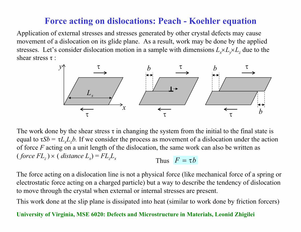
Application of external stresses and stresses generated by other crystal defects may cause movement of a dislocation on its glide plane. As a result, work may be done by the applied stresses. Let’s consider dislocation motion in a sample with dimensions Lx×Ly×Lz due to the shear stress τ :
x
Force acting on dislocations: Peach - Koehler equation
The force acting on a dislocation line is not a physical force (like mechanical force of a spring or electrostatic force acting on a charged particle) but a way to describe the tendency of dislocation to move through the crystal when external or internal stresses are present. This work done at the slip plane is dissipated into heat (similar to work done by friction forcers)
y
τ
τ
τ
τ
τ
τ
b
bb
xL
The work done by the shear stress τ in changing the system from the initial to the final state is equal to τSb = τLxLzb. If we consider the process as movement of a dislocation under the action of force F acting on a unit length of the dislocation, the same work can also be written as( force FLz ) × ( distance Lx) = FLzLx Thus bF τ=
University of Virginia, MSE 6020: Defects and Microstructure in Materials, Leonid Zhigilei
bF τ=
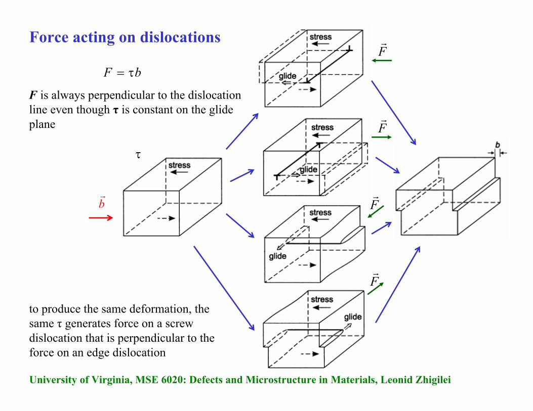
F is always perpendicular to the dislocation line even though τ is constant on the glide plane
Force acting on dislocations
to produce the same deformation, the same τ generates force on a screw dislocation that is perpendicular to the force on an edge dislocation
br
τ
Fr
Fr
Fr
Fr

University of Virginia, MSE 6020: Defects and Microstructure in Materials, Leonid Zhigilei
Since the dislocation moves on its glide plane, we only need to consider the shear stress on this plane. Stress components normal to the glide plane do not contribute to the dislocation movement
τ is the shear stress in the glide plane resolved in the direction of b and F acts normal to the dislocation linebF τ=
Moreover, only the shear stress components in the direction of b (called the resolved shear stress τ) are contribution to the movement of the dislocation.
yyσ
yyσ
br
τ
Fr
x
y
F is perpendicular to the dislocation lineτ is constant on the glide plane
( ) lbFrrr
×⋅σ=In general: Peach-Koehler equation
Fr
σ
lr
br⋅σ
- force per unit length at an arbitrary point Palong the dislocation line
- local stress field
- local line tangent direction at point P
- local force per unit length acting on a plane (of area b) normal to the Burgers vector
Force acting on dislocations: Peach - Koehler equation
University of Virginia, MSE 6020: Defects and Microstructure in Materials, Leonid Zhigilei
( ) lbFrrr
×⋅σ=
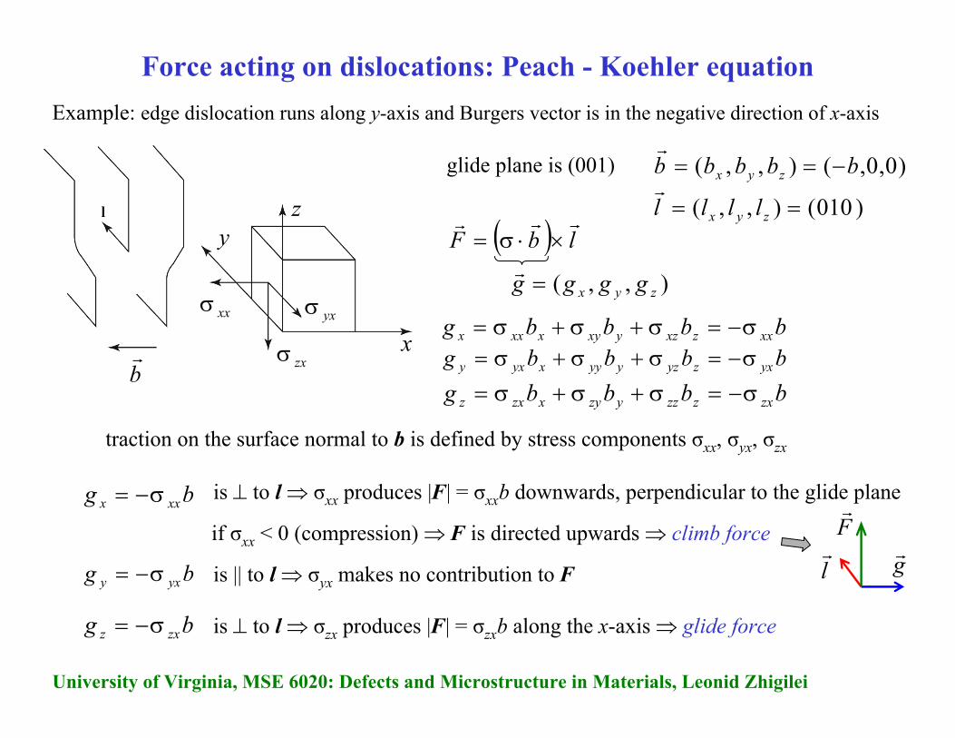
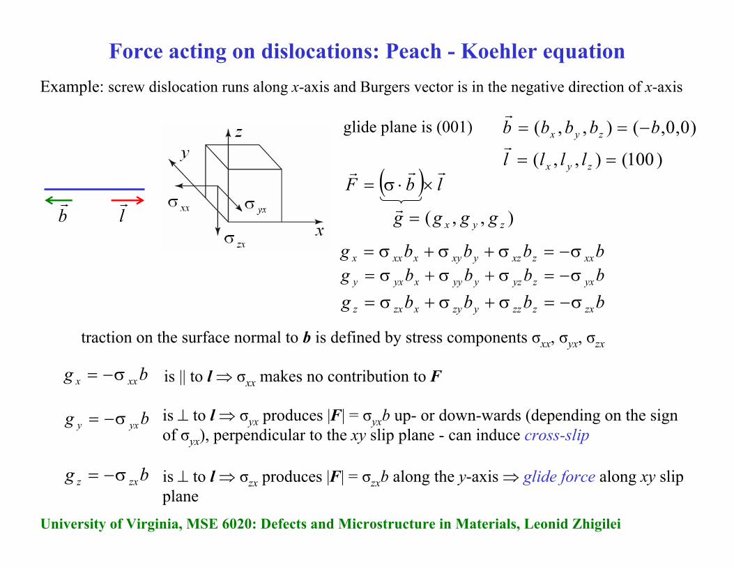
Example: edge dislocation runs along y-axis and Burgers vector is in the negative direction of x-axis
x
yz
xxσ
zxσ
yxσ
glide plane is (001)
traction on the surface normal to b is defined by stress components σxx, σyx, σzx
bbbbg xxzxzyxyxxxx σ−=σ+σ+σ=bbbbg yxzyzyyyxyxy σ−=σ+σ+σ=bbbbg zxzzzyzyxzxz σ−=σ+σ+σ=
)0,0,(),,( bbbbb zyx −==r
),,( zyx gggg =r
)010(),,( == zyx llllr
bg xxx σ−=
bg zxz σ−=
is || to l⇒ σyx makes no contribution to Fbg yxy σ−=
is ⊥ to l⇒ σxx produces |F| = σxxb downwards, perpendicular to the glide plane
if σxx < 0 (compression) ⇒ F is directed upwards ⇒ climb force
br
is ⊥ to l⇒ σzx produces |F| = σzxb along the x-axis ⇒ glide force
Force acting on dislocations: Peach - Koehler equation
grlr
Fr
University of Virginia, MSE 6020: Defects and Microstructure in Materials, Leonid Zhigilei
( ) lbFrrr
×⋅σ=
Example: screw dislocation runs along x-axis and Burgers vector is in the negative direction of x-axis
x
glide plane is (001) )0,0,(),,( bbbbb zyx −==r
),,( zyx gggg =r
)100(),,( == zyx llllr
bg xxx σ−=
bg zxz σ−=
is ⊥ to l⇒ σyx produces |F| = σyxb up- or down-wards (depending on the sign of σyx), perpendicular to the xy slip plane - can induce cross-slip
bg yxy σ−=
is || to l⇒ σxx makes no contribution to F
is ⊥ to l⇒ σzx produces |F| = σzxb along the y-axis ⇒ glide force along xy slip plane
Force acting on dislocations: Peach - Koehler equation
lr
br
bbbbg xxzxzyxyxxxx σ−=σ+σ+σ=bbbbg yxzyzyyyxyxy σ−=σ+σ+σ=bbbbg zxzzzyzyxzxz σ−=σ+σ+σ=
traction on the surface normal to b is defined by stress components σxx, σyx, σzx
University of Virginia, MSE 6020: Defects and Microstructure in Materials, Leonid Zhigilei
( ) lbFrrr
×⋅σ=
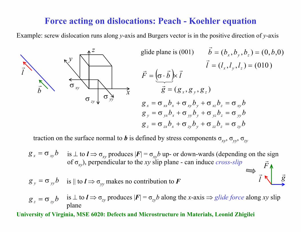
Example: screw dislocation runs along y-axis and Burgers vector is in the positive direction of y-axis
x
yz
yyσzyσ
xyσ
glide plane is (001)
traction on the surface normal to b is defined by stress components σxy, σyy, σzy
bbbbg xyzxzyxyxxxx σ=σ+σ+σ=bbbbg yyzyzyyyxyxy σ=σ+σ+σ=bbbbg zyzzzyzyxzxz σ=σ+σ+σ=
)0,,0(),,( bbbbb zyx ==r
),,( zyx gggg =r
)010(),,( == zyx llllr
bg xyx σ=
bg zyz σ=
is || to l⇒ σyy makes no contribution to Fbg yyy σ=
is ⊥ to l⇒ σxy produces |F| = σxyb up- or down-wards (depending on the sign of σxy), perpendicular to the xy slip plane - can induce cross-slip
is ⊥ to l⇒ σzy produces |F| = σzyb along the x-axis ⇒ glide force along xy slip plane
Force acting on dislocations: Peach - Koehler equation
grlr
Fr
lr
br

University of Virginia, MSE 6020: Defects and Microstructure in Materials, Leonid Zhigilei
Forces between dislocations
Example: interaction between two parallel straight edge dislocations
Force due to the interaction with other dislocations = sum of all Peach–Koehler forces between the segments of all other dislocations in the system
Edge dislocation (1) produces a stress field that dislocation (2) responds to
Peach–Koehler gives force acting on dislocation (2) due to the presence of dislocation (1)
Must use consistent convention to describe dislocations (direction of the Burgers circuit, line direction into page, start-finish)
x
y
(1)
(2)
z
( ) lbFrrr
×⋅σ=
),,( zyx gggg =r
(2)(1)
zxzyxyxxxx bbbg σ+σ+σ=
zyzyyyxyxy bbbg σ+σ+σ=
zzzyzyxzxz bbbg σ+σ+σ=
),,( zyx bbbb =r
),,( zyx llll =r disl. (2)

University of Virginia, MSE 6020: Defects and Microstructure in Materials, Leonid Zhigilei
Forces between dislocationsExample: interaction between two parallel straight edge dislocations
( ) 22 lbFrrr
×⋅σ=
gr
(2)(1)
2bbbbg xxzxzyxyxxxx σ=σ+σ+σ=
2bbbbg yxzyzyyyxyxy σ=σ+σ+σ=
0=σ+σ+σ= zzzyzyxzxz bbbg
)0,0,( 1bb =r
)1,0,0(1 =lr
(1)
(2)
y
x
(1) )0,0,( 2bb =r
)1,0,0(2 =lr
(2)
(2) disl.for )0,0,( 2bb =r
(1) disl. from σ
Step 1:
Step 2:
)0,,( 22 bbg yxxx σσ=r
)0,,( 222 bblgF xxyx σ−σ=×=rrr
Step 3:
use expressions for stresses generated by dislocation (1):
( )( )222
221 3
)1(2 yxyxyGb
xx+
+ν−π
−=σ
( )( )222
221
)1(2 yxyxxGb
xy+
−ν−π
=σ
( )( )
( )( ) y
yxyxybGbx
yxyxxbGbF ˆ3
)1(2ˆ
)1(2 222
2221
222
2221
+
+ν−π
++
−ν−π
=r
a × b = c = c1i + c2j + c3k
University of Virginia, MSE 6020: Defects and Microstructure in Materials, Leonid Zhigilei
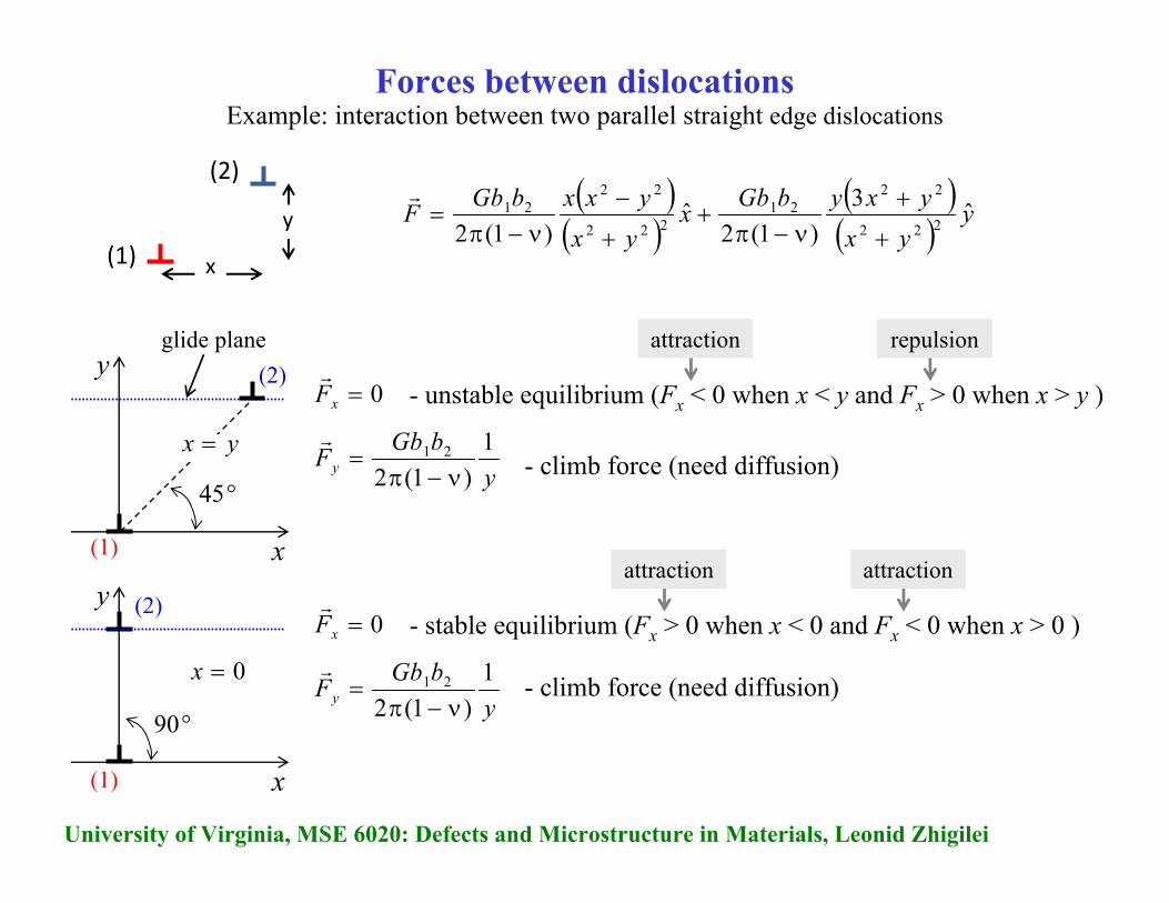
Forces between dislocationsExample: interaction between two parallel straight edge dislocations
(1)
(2)
y
x
( )( )
( )( ) y
yxyxybGbx
yxyxxbGbF ˆ3
)1(2ˆ
)1(2 222
2221
222
2221
+
+ν−π
++
−ν−π
=r
x
y
°45 ybGbFy
1)1(2
21
ν−π=
ryx =
0=xFr
- unstable equilibrium (Fx < 0 when x < y and Fx > 0 when x > y )
repulsionattraction
x
y
°90 ybGbFy
1)1(2
21
ν−π=
r0=x
0=xFr
- stable equilibrium (Fx > 0 when x < 0 and Fx < 0 when x > 0 )
attractionattraction
- climb force (need diffusion)
- climb force (need diffusion)
glide plane(2)
(1)
(2)
(1)
University of Virginia, MSE 6020: Defects and Microstructure in Materials, Leonid Zhigilei
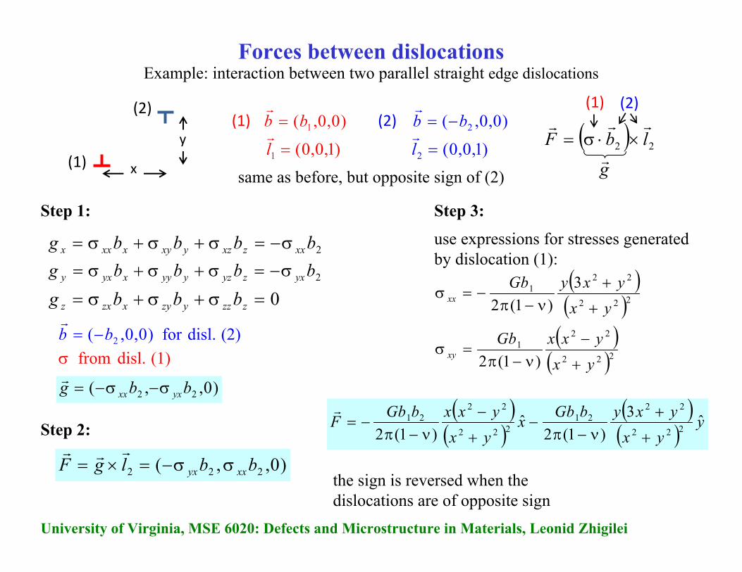
Forces between dislocationsExample: interaction between two parallel straight edge dislocations
( ) 22 lbFrrr
×⋅σ=
gr
(2)(1)
2bbbbg xxzxzyxyxxxx σ−=σ+σ+σ=
2bbbbg yxzyzyyyxyxy σ−=σ+σ+σ=
0=σ+σ+σ= zzzyzyxzxz bbbg
)0,0,( 1bb =r
)1,0,0(1 =lr
(1)
(2)
y
x
(1) )0,0,( 2bb −=r
)1,0,0(2 =lr
(2)
(2) disl.for )0,0,( 2bb −=r
(1) disl. from σ
Step 1:
Step 2:
)0,,( 22 bbg yxxx σ−σ−=r
)0,,( 222 bblgF xxyx σσ−=×=rrr
Step 3:
use expressions for stresses generated by dislocation (1):
( )( )222
221 3
)1(2 yxyxyGb
xx+
+ν−π
−=σ
( )( )222
221
)1(2 yxyxxGb
xy+
−ν−π
=σ
( )( )
( )( ) y
yxyxybGbx
yxyxxbGbF ˆ3
)1(2ˆ
)1(2 222
2221
222
2221
+
+ν−π
−+
−ν−π
−=r
same as before, but opposite sign of (2)
the sign is reversed when the dislocations are of opposite sign
University of Virginia, MSE 6020: Defects and Microstructure in Materials, Leonid Zhigilei
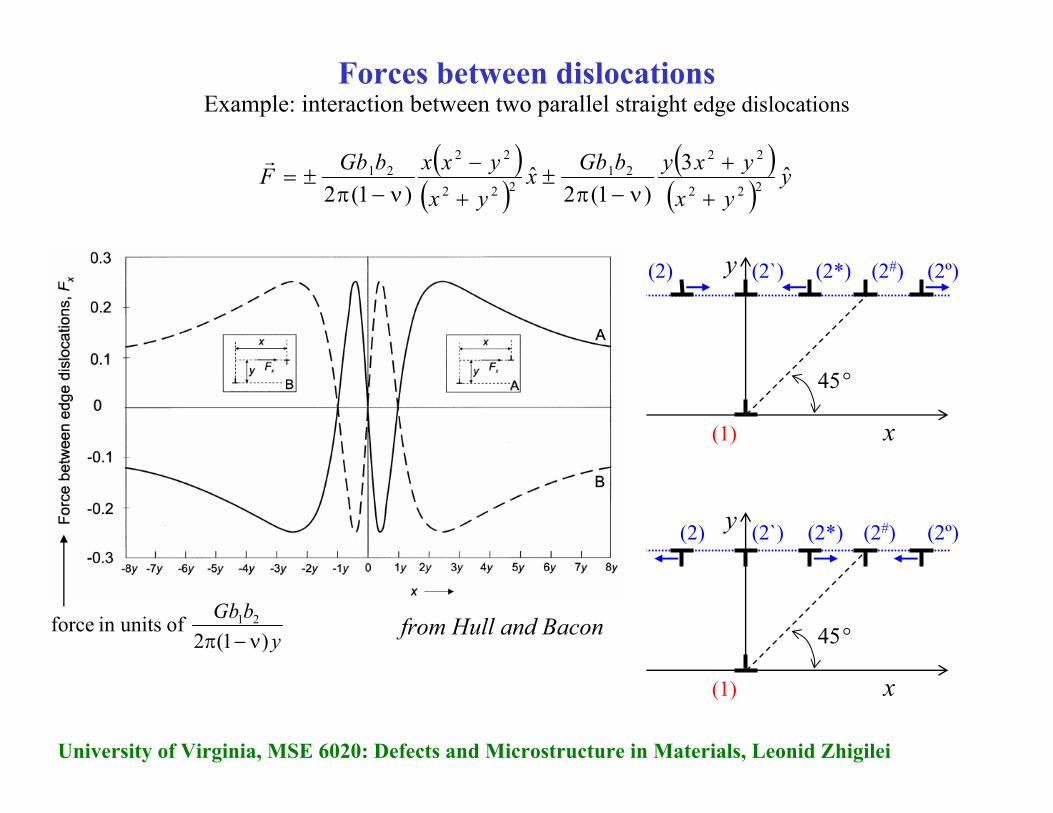
Forces between dislocationsExample: interaction between two parallel straight edge dislocations
( )( )
( )( ) y
yxyxybGbx
yxyxxbGbF ˆ3
)1(2ˆ
)1(2 222
2221
222
2221
+
+ν−π
±+
−ν−π
±=r
x
y
°45
(1)
(2) (2*)(2`) (2º)(2#)
x
y
°45
(1)
(2) (2*)(2`) (2º)(2#)
ybGb
)1(2 of unitsin force 21
ν−πfrom Hull and Bacon
University of Virginia, MSE 6020: Defects and Microstructure in Materials, Leonid Zhigilei
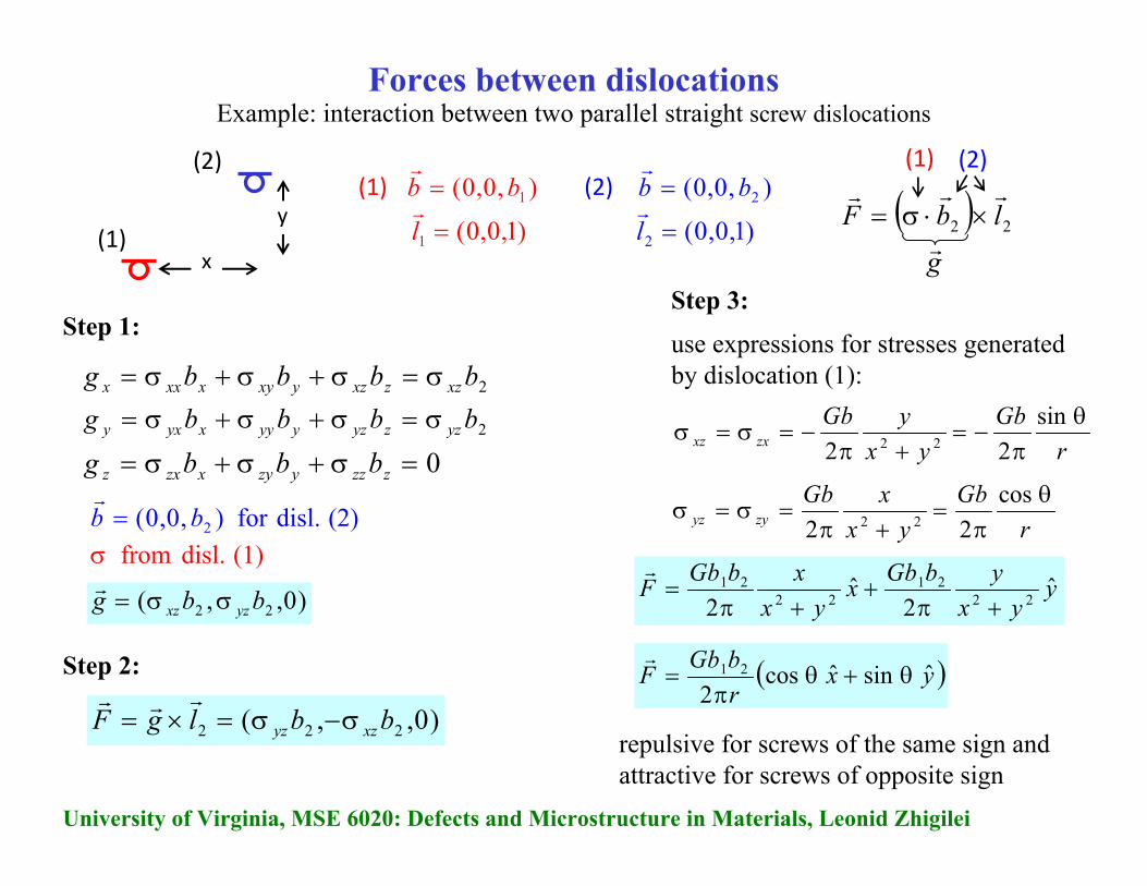
Forces between dislocationsExample: interaction between two parallel straight screw dislocations
( ) 22 lbFrrr
×⋅σ=
gr
(2)(1)
2bbbbg xzzxzyxyxxxx σ=σ+σ+σ=
2bbbbg yzzyzyyyxyxy σ=σ+σ+σ=
0=σ+σ+σ= zzzyzyxzxz bbbg
),0,0( 1bb =r
)1,0,0(1 =lr
(1)
(2)
y
x
(1) ),0,0( 2bb =r
)1,0,0(2 =lr
(2)
(2) disl.for ),0,0( 2bb =r
(1) disl. from σ
Step 1:
Step 2:
)0,,( 22 bbg yzxz σσ=r
)0,,( 222 bblgF xzyz σ−σ=×=rrr
Step 3:
use expressions for stresses generated by dislocation (1):
yyx
ybGbxyx
xbGbF ˆ2
ˆ2 22
2122
21
+π+
+π=
r
rGb
yxxGb
zyyzθ
π=
+π=σ=σ
cos22 22
rGb
yxyGb
zxxzθ
π−=
+π−=σ=σ
sin22 22
( )yxrbGbF ˆ sinˆ cos
221 θ+θ
π=
r
repulsive for screws of the same sign and attractive for screws of opposite sign
University of Virginia, MSE 6020: Defects and Microstructure in Materials, Leonid Zhigilei
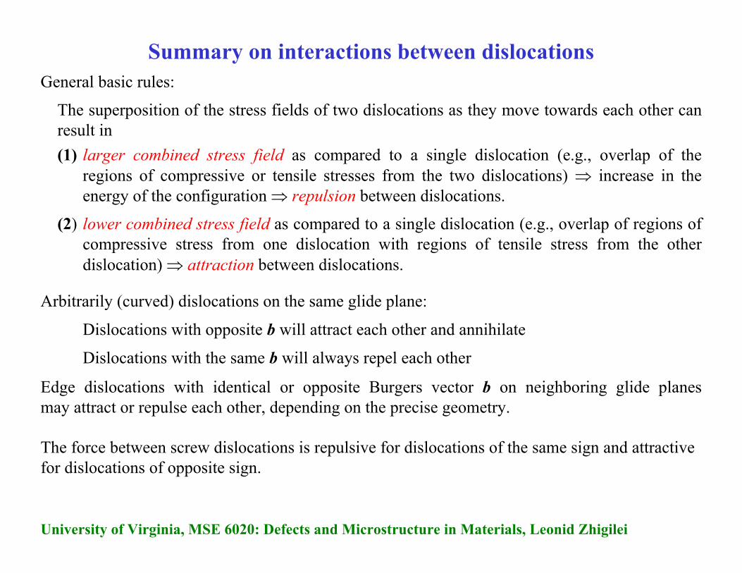
Summary on interactions between dislocations
Arbitrarily (curved) dislocations on the same glide plane:
Dislocations with opposite b will attract each other and annihilate
Dislocations with the same b will always repel each other
General basic rules:
The superposition of the stress fields of two dislocations as they move towards each other can result in (1) larger combined stress field as compared to a single dislocation (e.g., overlap of the
regions of compressive or tensile stresses from the two dislocations) ⇒ increase in the energy of the configuration ⇒ repulsion between dislocations.
(2) lower combined stress field as compared to a single dislocation (e.g., overlap of regions of compressive stress from one dislocation with regions of tensile stress from the other dislocation) ⇒ attraction between dislocations.
Edge dislocations with identical or opposite Burgers vector b on neighboring glide planes may attract or repulse each other, depending on the precise geometry.
The force between screw dislocations is repulsive for dislocations of the same sign and attractive for dislocations of opposite sign.
University of Virginia, MSE 6020: Defects and Microstructure in Materials, Leonid Zhigilei
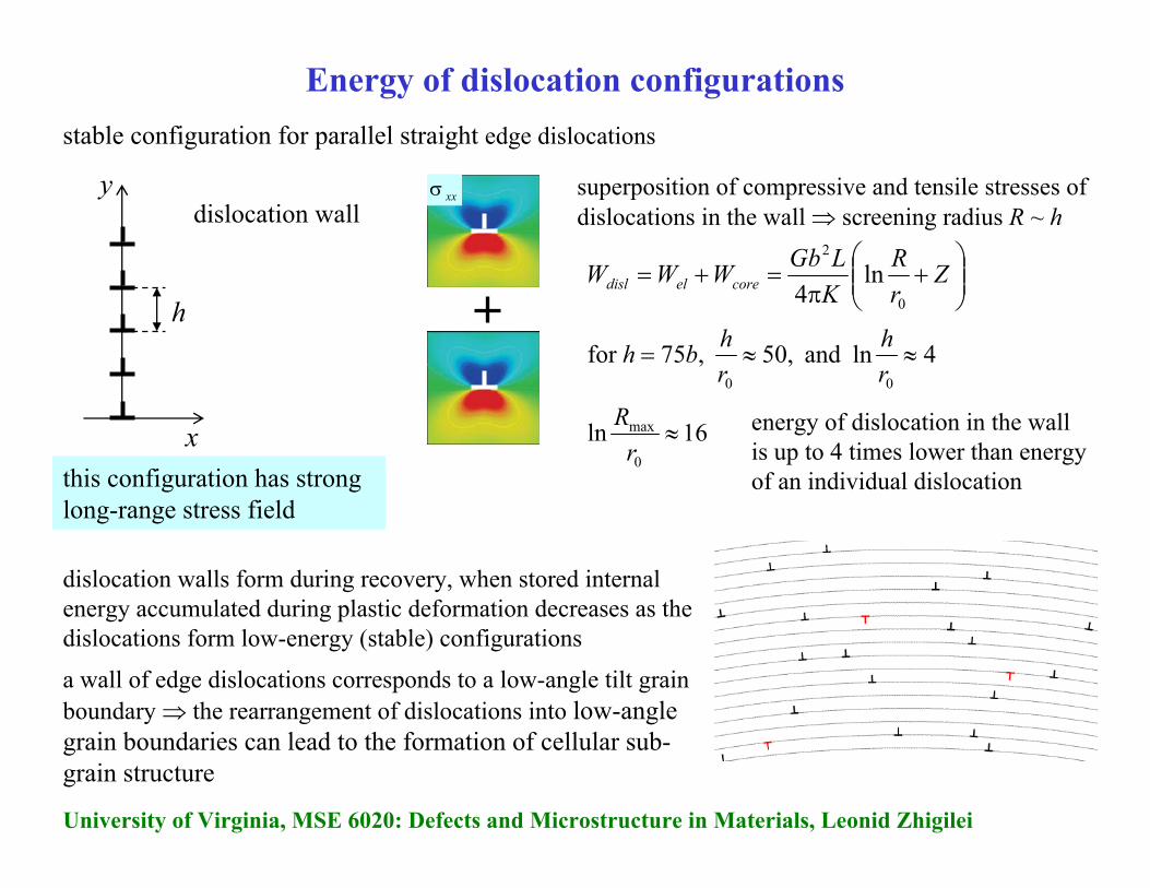
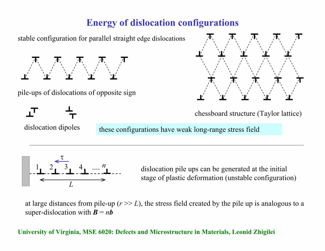
Energy of dislocation configurationsstable configuration for parallel straight edge dislocations
y
x
dislocation wallxxσ superposition of compressive and tensile stresses of
dislocations in the wall ⇒ screening radius R ~ h
⎟⎟⎠
⎞⎜⎜⎝
⎛+
π=+= Z
rR
KLGbWWW coreeldisl
0
2
ln4
4ln and 50, ,75for 00
≈≈=rh
rhbh
16ln0
max ≈r
R energy of dislocation in the wall is up to 4 times lower than energy of an individual dislocation
dislocation walls form during recovery, when stored internal energy accumulated during plastic deformation decreases as the dislocations form low-energy (stable) configurations
a wall of edge dislocations corresponds to a low-angle tilt grain boundary ⇒ the rearrangement of dislocations into low-angle grain boundaries can lead to the formation of cellular sub-grain structure
h
this configuration has strong long-range stress field
University of Virginia, MSE 6020: Defects and Microstructure in Materials, Leonid Zhigilei
Energy of dislocation configurationsstable configuration for parallel straight edge dislocations
dislocation pile ups can be generated at the initial stage of plastic deformation (unstable configuration)
pile-ups of dislocations of opposite sign
chessboard structure (Taylor lattice)
dislocation dipoles these configurations have weak long-range stress field
τ
at large distances from pile-up (r >> L), the stress field created by the pile up is analogous to a super-dislocation with B = nb
....1 2 3 4 n
L
University of Virginia, MSE 6020: Defects and Microstructure in Materials, Leonid Zhigilei
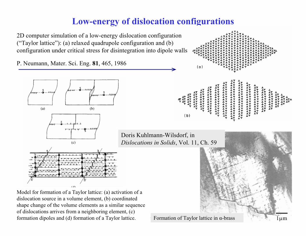
Low-energy of dislocation configurations
P. Neumann, Mater. Sci. Eng. 81, 465, 1986
2D computer simulation of a low-energy dislocation configuration (“Taylor lattice”): (a) relaxed quadrupole configuration and (b) configuration under critical stress for disintegration into dipole walls
Model for formation of a Taylor lattice: (a) activation of a dislocation source in a volume element, (b) coordinated shape change of the volume elements as a similar sequence of dislocations arrives from a neighboring element, (c) formation dipoles and (d) formation of a Taylor lattice. Formation of Taylor lattice in α-brass m 1μ
Doris Kuhlmann-Wilsdorf, in Dislocations in Solids, Vol. 11, Ch. 59
University of Virginia, MSE 6020: Defects and Microstructure in Materials, Leonid Zhigilei
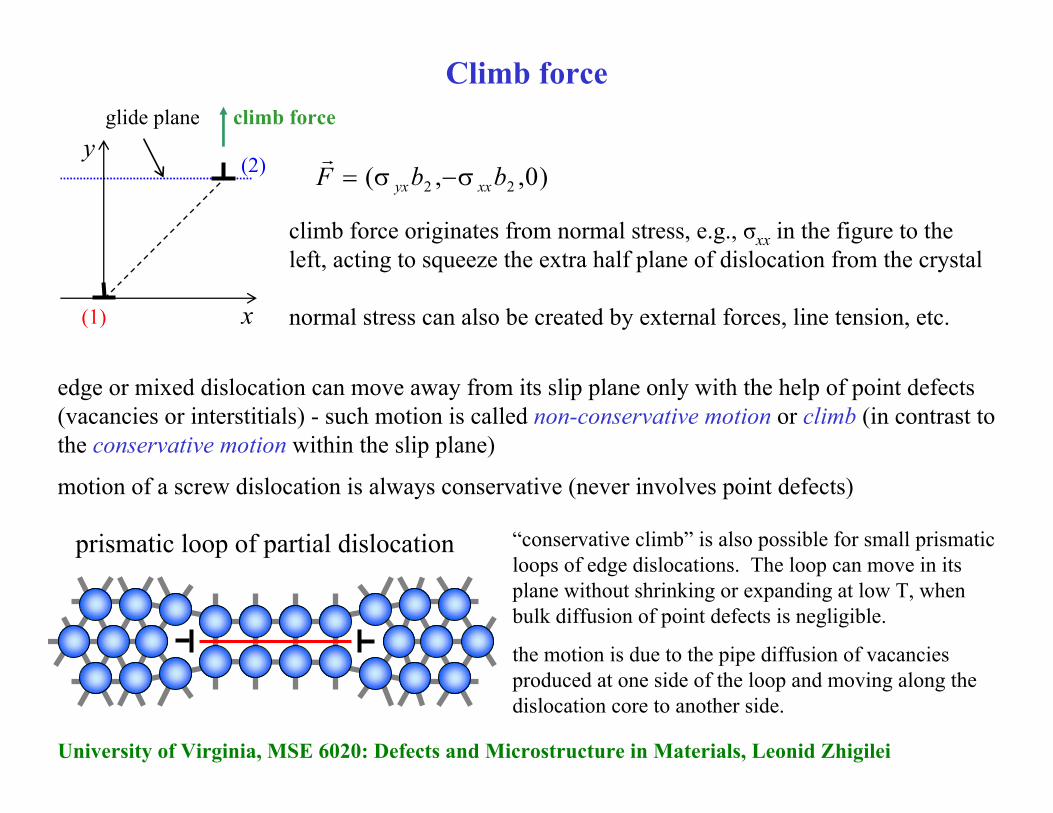
Climb force
x
yglide plane
)0,,( 22 bbF xxyx σ−σ=r(2)
(1)
climb force
climb force originates from normal stress, e.g., σxx in the figure to the left, acting to squeeze the extra half plane of dislocation from the crystal
normal stress can also be created by external forces, line tension, etc.
edge or mixed dislocation can move away from its slip plane only with the help of point defects (vacancies or interstitials) - such motion is called non-conservative motion or climb (in contrast to the conservative motion within the slip plane)
motion of a screw dislocation is always conservative (never involves point defects)
“conservative climb” is also possible for small prismatic loops of edge dislocations. The loop can move in its plane without shrinking or expanding at low T, when bulk diffusion of point defects is negligible.
the motion is due to the pipe diffusion of vacancies produced at one side of the loop and moving along the dislocation core to another side.
prismatic loop of partial dislocation
University of Virginia, MSE 6020: Defects and Microstructure in Materials, Leonid Zhigilei
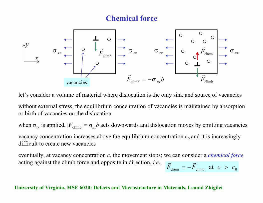
Chemical force
let’s consider a volume of material where dislocation is the only sink and source of vacancies
without external stress, the equilibrium concentration of vacancies is maintained by absorption or birth of vacancies on the dislocation
when σxx is applied, |Fclimb| = σxxb acts downwards and dislocation moves by emitting vacancies
vacancy concentration increases above the equilibrium concentration c0 and it is increasingly difficult to create new vacancies
eventually, at vacancy concentration c, the movement stops; we can consider a chemical forceacting against the climb force and opposite in direction, i.e.,
climbFr
x
yxxσxxσ
0climbchem at c c FF >−=rr
climbFr
xxσxxσchemFr
vacancies bF xxσ−=climb
r
University of Virginia, MSE 6020: Defects and Microstructure in Materials, Leonid Zhigilei
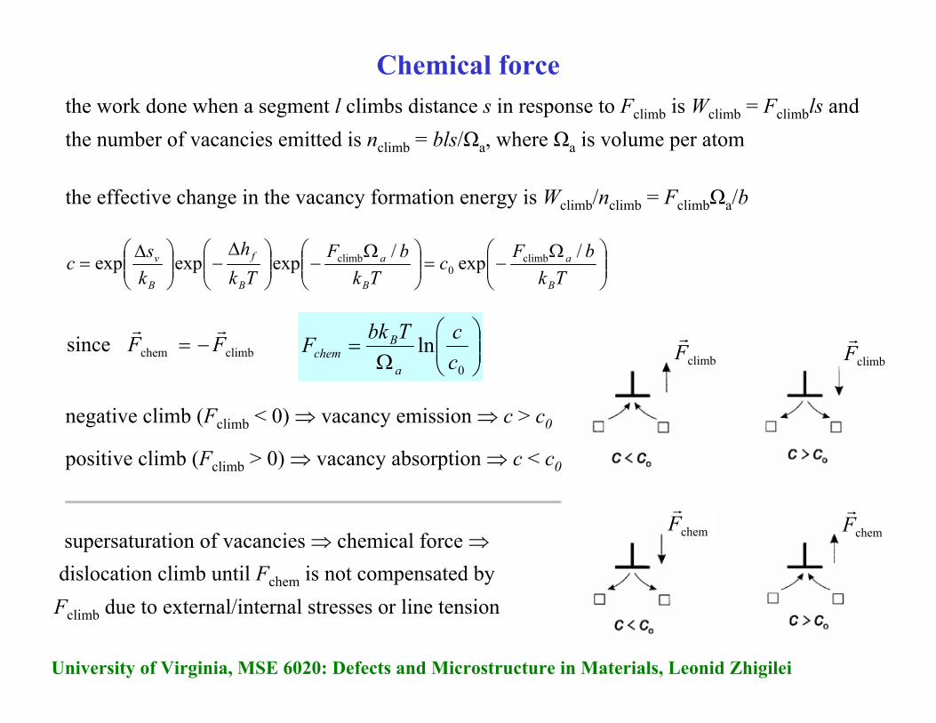
Chemical forcethe work done when a segment l climbs distance s in response to Fclimb is Wclimb = Fclimbls and the number of vacancies emitted is nclimb = bls/Ωa, where Ωa is volume per atom
the effective change in the vacancy formation energy is Wclimb/nclimb = FclimbΩa/b
negative climb (Fclimb < 0) ⇒ vacancy emission ⇒ c > c0
⎟⎟⎠
⎞⎜⎜⎝
⎛ Ω−=⎟⎟
⎠
⎞⎜⎜⎝
⎛ Ω−⎟⎟
⎠
⎞⎜⎜⎝
⎛ Δ−⎟⎟
⎠
⎞⎜⎜⎝
⎛ Δ=
TkbFc
TkbF
Tkh
ksc
B
a
B
a
B
f
B
v /exp/expexpexp climb0
climb
climbchem since FFrr
−= ⎟⎟⎠
⎞⎜⎜⎝
⎛Ω
=0
lnccTbkF
a
Bchem
positive climb (Fclimb > 0) ⇒ vacancy absorption ⇒ c < c0
chemFr
climbFr
chemFr
climbFr
supersaturation of vacancies ⇒ chemical force ⇒dislocation climb until Fchem is not compensated by Fclimb due to external/internal stresses or line tension
University of Virginia, MSE 6020: Defects and Microstructure in Materials, Leonid Zhigilei
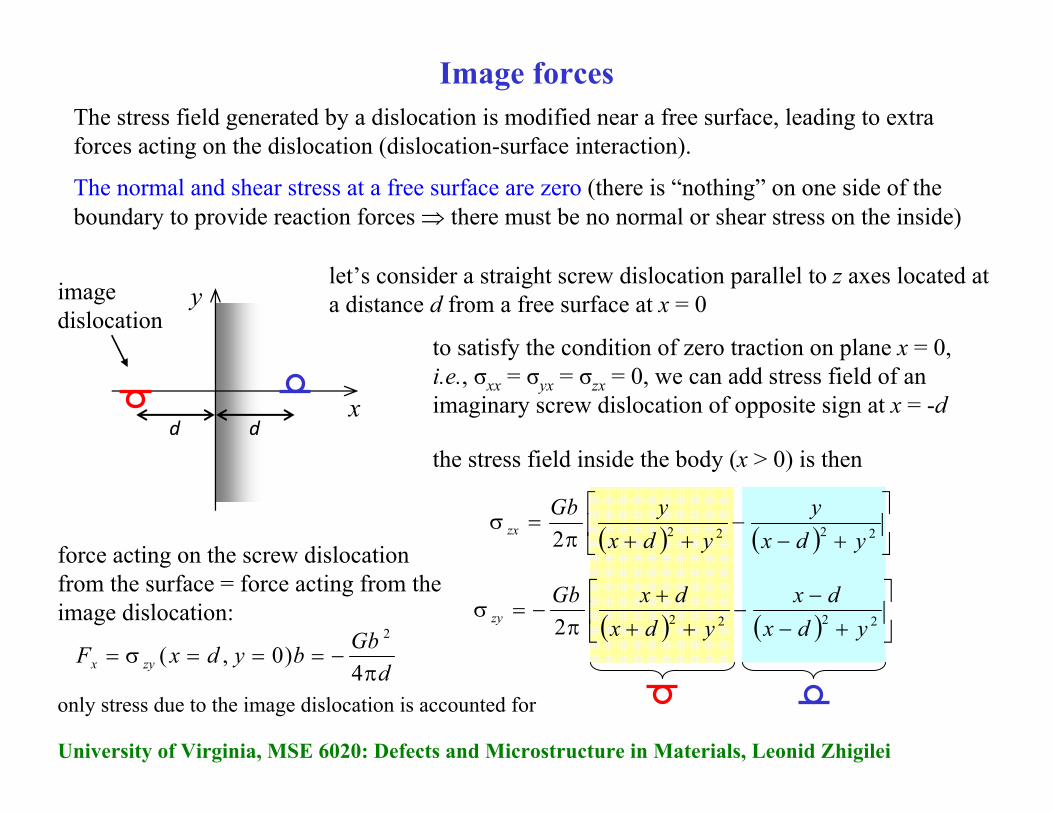
Image forcesThe stress field generated by a dislocation is modified near a free surface, leading to extra forces acting on the dislocation (dislocation-surface interaction).
The normal and shear stress at a free surface are zero (there is “nothing” on one side of the boundary to provide reaction forces ⇒ there must be no normal or shear stress on the inside)
x
y
d d
imagedislocation
let’s consider a straight screw dislocation parallel to z axes located at a distance d from a free surface at x = 0
to satisfy the condition of zero traction on plane x = 0, i.e., σxx = σyx = σzx = 0, we can add stress field of an imaginary screw dislocation of opposite sign at x = -d
( ) ( ) ⎥⎦
⎤⎢⎣
⎡
+−−
++π=σ
22222 ydxy
ydxyGb
zx
the stress field inside the body (x > 0) is then
( ) ( ) ⎥⎦
⎤⎢⎣
⎡
+−−
−++
+π
−=σ22222 ydx
dxydx
dxGbzy
dGbbydxF zyx π
−===σ=4
)0,(2
force acting on the screw dislocation from the surface = force acting from the image dislocation:
only stress due to the image dislocation is accounted for
University of Virginia, MSE 6020: Defects and Microstructure in Materials, Leonid Zhigilei
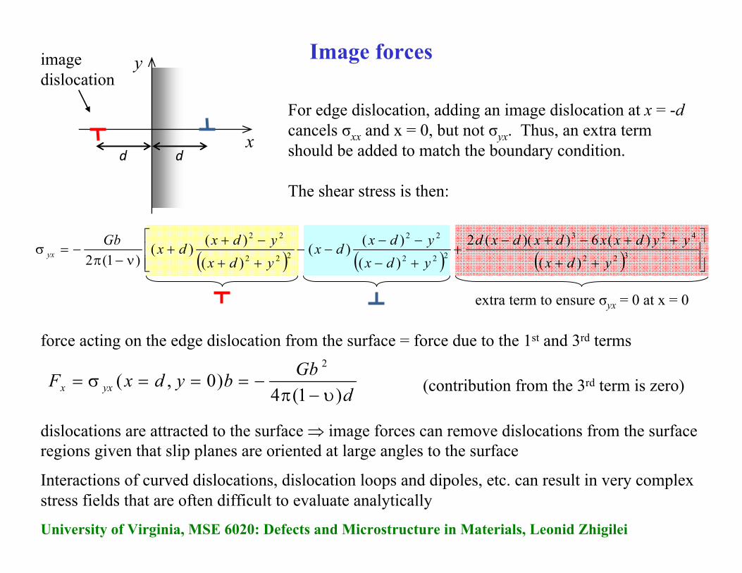
Image forces
For edge dislocation, adding an image dislocation at x = -dcancels σxx and x = 0, but not σyx. Thus, an extra term should be added to match the boundary condition.
The shear stress is then:
x
y
d d
imagedislocation
(contribution from the 3rd term is zero)
extra term to ensure σyx = 0 at x = 0
dGbbydxF yxx )1(4
)0,(2
υ−π−===σ=
force acting on the edge dislocation from the surface = force due to the 1st and 3rd terms
( ) ( ) ( ) ⎥⎥⎦
⎤
⎢⎢⎣
⎡
++
++−+−+
+−
−−−−
++
−++
ν−π−=σ 322
423
222
22
222
22
)()(6))((2
)()()(
)()()(
)1(2 ydxyydxxdxdxd
ydxydxdx
ydxydxdxGb
yx
dislocations are attracted to the surface ⇒ image forces can remove dislocations from the surface regions given that slip planes are oriented at large angles to the surface
Interactions of curved dislocations, dislocation loops and dipoles, etc. can result in very complex stress fields that are often difficult to evaluate analytically

University of Virginia, MSE 6020: Defects and Microstructure in Materials, Leonid Zhigilei
Line tension
Recall the result of our analysis of the dislocation energy: ⎟⎟⎠
⎞⎜⎜⎝
⎛+
π=+= Z
rR
KLGbWWW coreeldisl
0
2
ln4
The line energy (energy per length) has the same dimension as a force and corresponds to line tension, i.e., a force in the direction of the line vector which tries to shorten the dislocation
2
0
2
ln4
GbZrR
KGb
LWdisl α≈⎟⎟
⎠
⎞⎜⎜⎝
⎛+
π= 5.15.0 −≈αor, for energy per unit length,
2GbLWT disl α≈=
The resulting force FT acting on an element dl of a dislocation line is related to the line tension T at the ends of the element and is perpendicular to the dislocation line
TFr
θ≈θ= TddTFT )2/sin(2r
θd smallfor
Rdld ≈θ
bdlF τ=τ
rforce Fτ acting on the same element dl due to the external shear stress is
balance of forces to maintain radius R of the curved dislocation: bdlTd τ=θ R
GbbRT
bdlTd α
==θ
=τ
University of Virginia, MSE 6020: Defects and Microstructure in Materials, Leonid Zhigilei
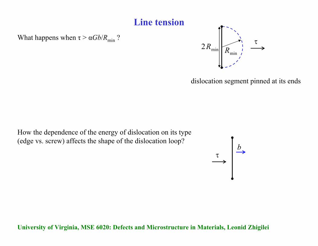
Line tension
How the dependence of the energy of dislocation on its type (edge vs. screw) affects the shape of the dislocation loop?
What happens when τ > αGb/Rmin ?min2R
minRτ
τb
dislocation segment pinned at its ends