forces b/w dislocations consider two parallel (//) edge dislocations lying in the same slip plane....
TRANSCRIPT
Forces B/w Dislocations
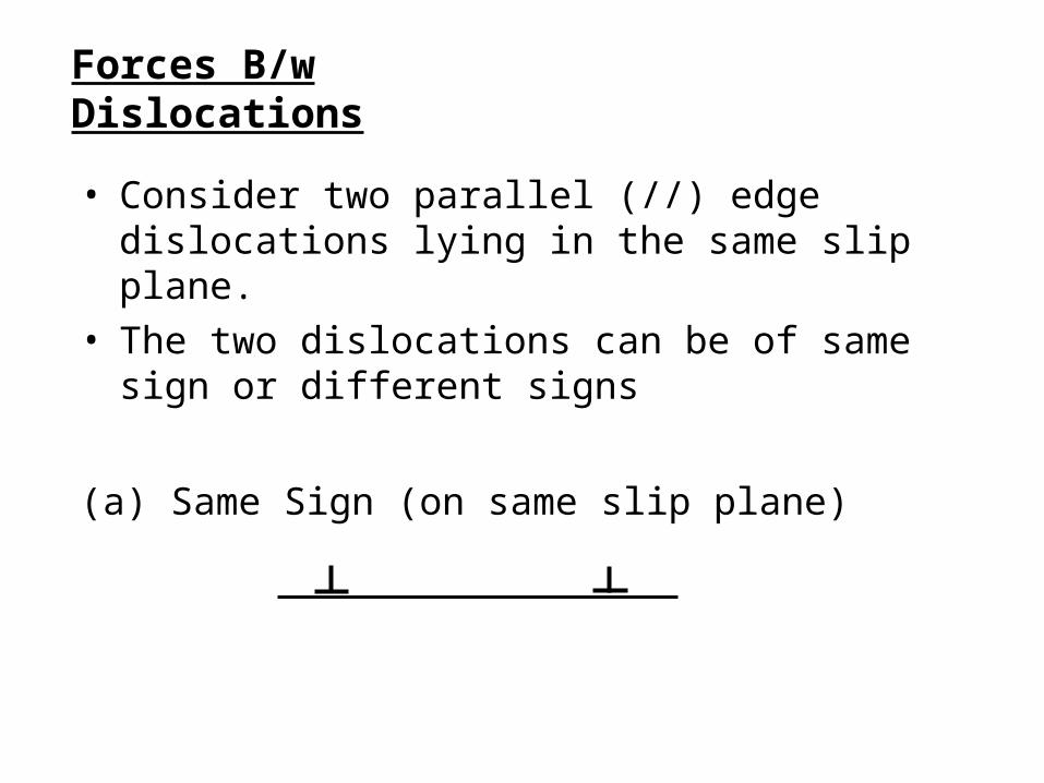
• Consider two parallel (//) edge dislocations lying in the same slip plane.
• The two dislocations can be of same sign or different signs
(a) Same Sign (on same slip plane)

• When the two dislocations are separated by large distance: The total elastic energy per unit length of the dislocation is given by:
• When dislocations are very close together: The arrangement can be considered approximately a single dislocation with Burgers vector = 2b
In order to reduce the total elastic energy, same sign dislocations will repel each other (i.e., prefer large distance separation).
222 2 GbGbGbU sep
22 42)( GbbGUEnergyElastic couple
(14.34)
(14.35)
sepcouple UU

• Dislocations of opposite sign (on same slip plane)
• If the dislocations are separated by large distance:
• If dislocations are close together: Burgers vector = b - b = 0
Hence, in order to reduce their total energy, dislocations of opposite signs will prefer to come together and annihilate (cancel) each other.
222 2)( GbbGGbU sep
couplesep
couple
UUand
U
0
• The same conclusions are obtained for dislocation of mixed orientations
• (a) and (b) above can be summarized as:– Like dislocations repel and – unlike dislocations attract
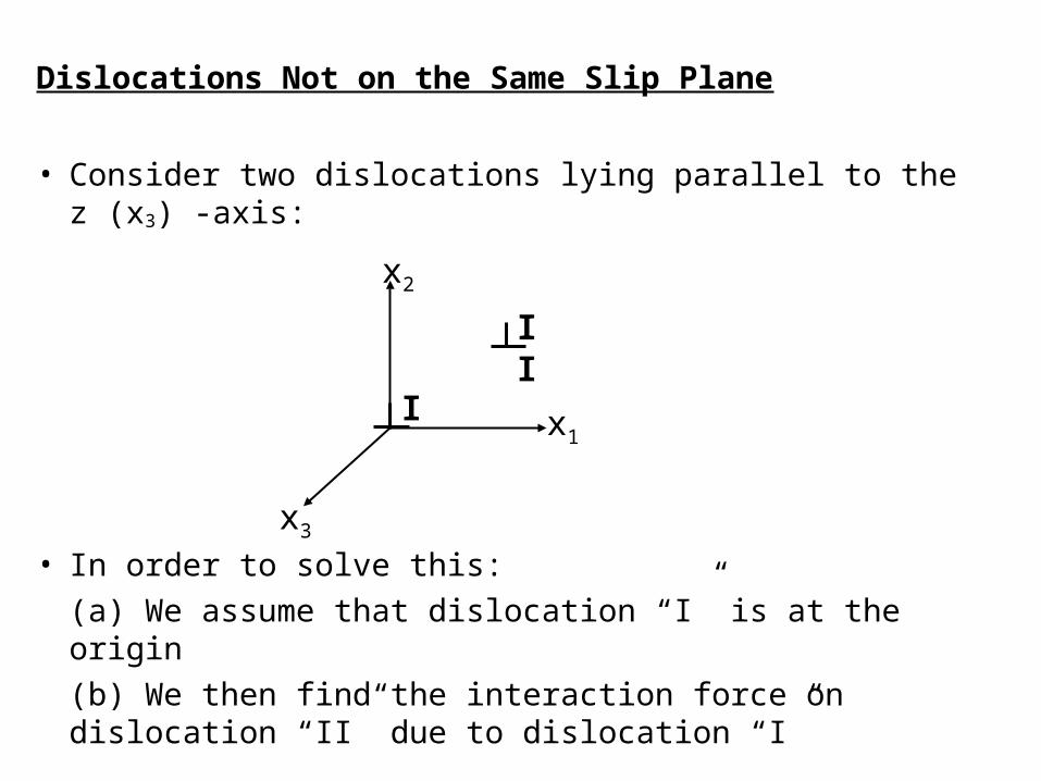
Dislocations Not on the Same Slip Plane
• Consider two dislocations lying parallel to the z (x3) -axis:
• In order to solve this:
(a) We assume that dislocation “I” is at the origin
(b) We then find the interaction force on dislocation “II” due to dislocation “I”
x2
x1
x3
I
II

• Recall Eqn. 14.29
• Note that the dislocation at the origin (dislocation I) provides the stress field, while the Burgers vector and the dislocation length belongs to dislocation II
• Since is edge:
• Also bII is parallel to x1: Therefore,
This means that b2 = b3 = 0 and b1 = b
tH
tbF IIIII
)(
14.29
I 032233113
0
0
b
bII
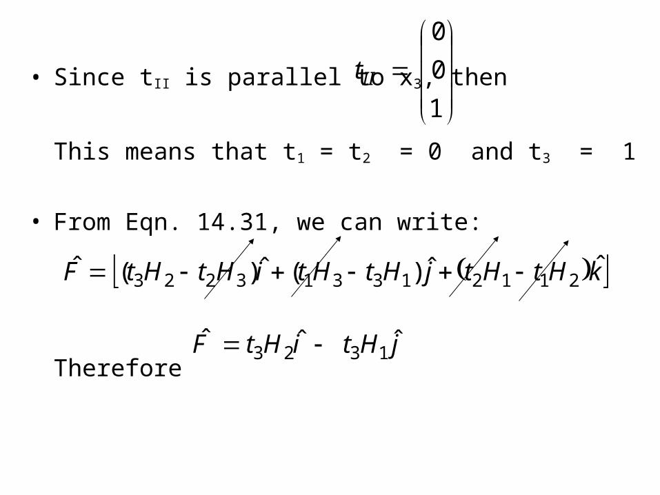
• Since tII is parallel to x3, then
This means that t1 = t2 = 0 and t3 = 1
• From Eqn. 14.31, we can write:
Therefore
1
0
0
IIt
kHtHtjHtHtiHtHtF ˆˆ)(ˆ)(ˆ211213313223
jHtiHtF ˆˆˆ1323
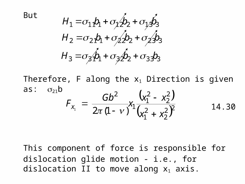
But
Therefore, F along the x1 Direction is given as: 21b
This component of force is responsible for dislocation glide motion - i.e., for dislocation II to move along x1 axis.
3132121111 bbbH
3232221212 bbbH
3332321313 bbbH
22
221
22
21
1
2
)1(21
xx
xxx
GbFx
14.30
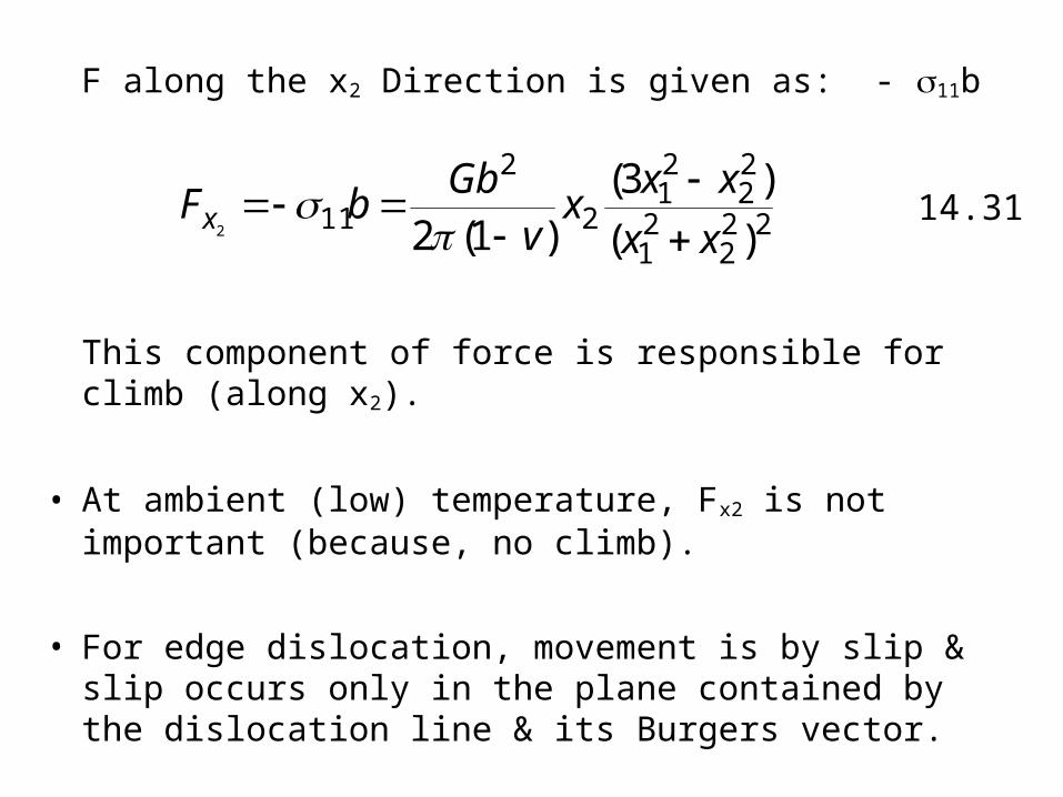
F along the x2 Direction is given as: - 11b
This component of force is responsible for climb (along x2).
• At ambient (low) temperature, Fx2 is not important (because, no climb).
• For edge dislocation, movement is by slip & slip occurs only in the plane contained by the dislocation line & its Burgers vector.
222
21
22
21
2
2
11)(
)3()1(22 xx
xxx
vGb
bFx
14.31
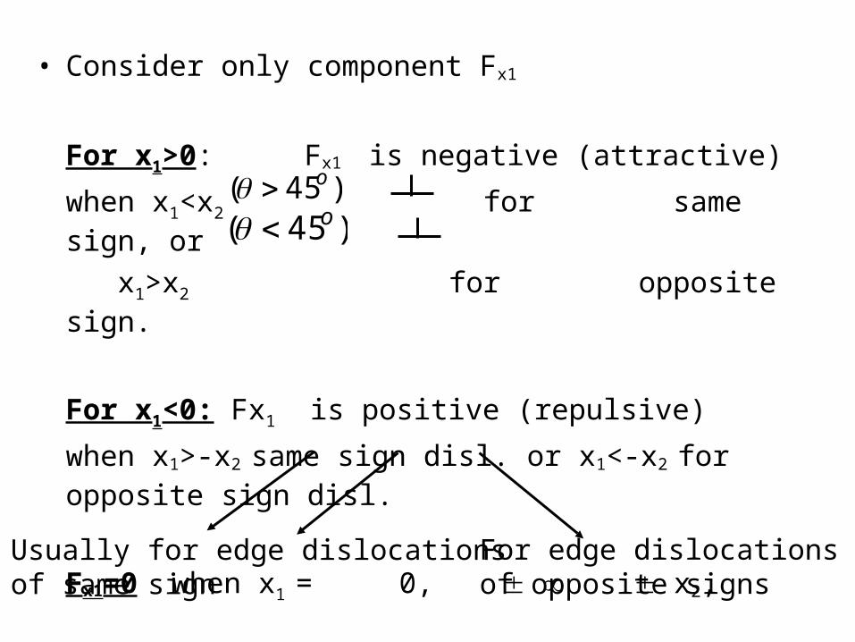
• Consider only component Fx1
For x1>0: Fx1 is negative (attractive)
when x1<x2 for same sign, or
x1>x2 for opposite sign.
For x1<0: Fx1 is positive (repulsive)
when x1>-x2 same sign disl. or x1<-x2 for opposite sign disl.
Fx1=0 when x1 = 0, x2,
)45( o)45( o
Usually for edge dislocationsof same sign
For edge dislocationsof opposite signs
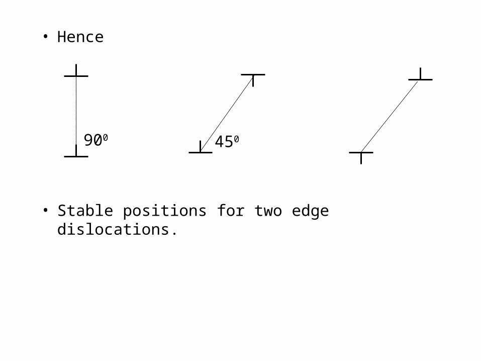
• Hence
• Stable positions for two edge dislocations.
900 450

• Equations 14-30 and 14-31 can also be obtained by considering both the radial and tangential components. The force per unit length is given by:
• Because edge dislocations are mainly confined to the plane, the force component along the the x direction, which is the slip direction, is of most interest, and is given by:
rGb
F
rGb
Fr
2sin
12
112
2
2
14.32
14.33
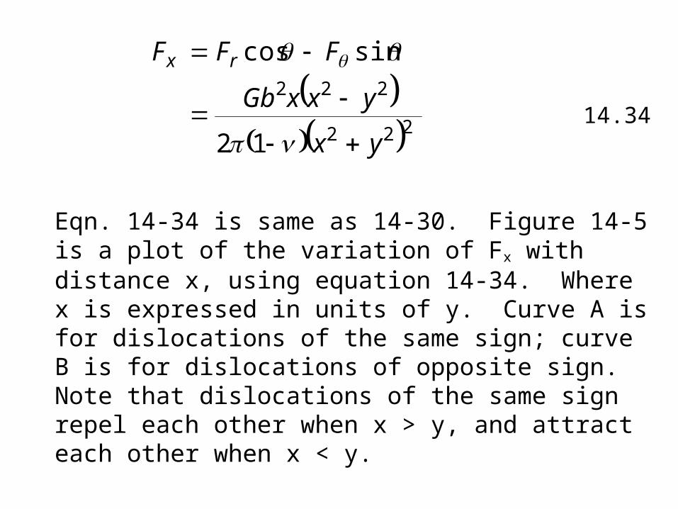
Eqn. 14-34 is same as 14-30. Figure 14-5 is a plot of the variation of Fx with distance x, using equation 14-34. Where x is expressed in units of y. Curve A is for dislocations of the same sign; curve B is for dislocations of opposite sign. Note that dislocations of the same sign repel each other when x > y, and attract each other when x < y.
222
222
12
sincos
yx
yxxGb
FFF rx
14.34
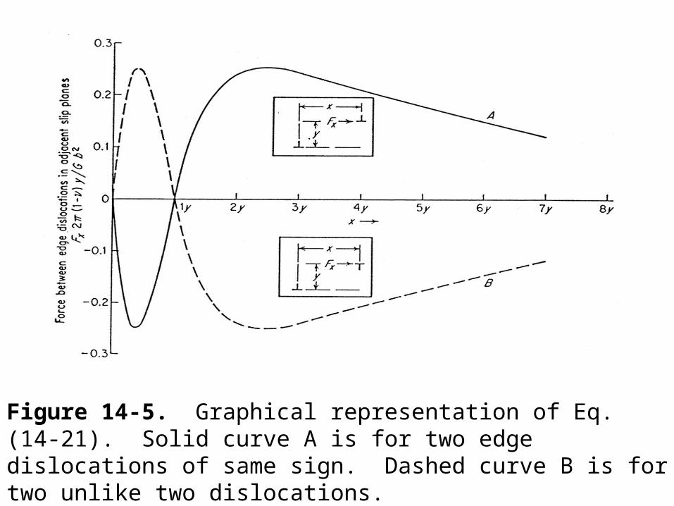
Figure 14-5. Graphical representation of Eq. (14-21). Solid curve A is for two edge dislocations of same sign. Dashed curve B is for two unlike two dislocations.

• Example: A dislocations lies parallel to [100] with Burgers vector b<110>. Compute the force acting on the dislocation due to the stress field of a neighboring screw dislocation lying parallel to [001].
Assume that for the screw dislocations yzxz
x2
x1
x3
Solution:
S
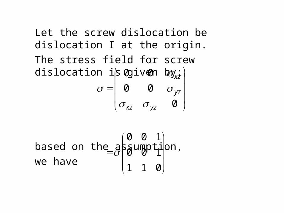
Let the screw dislocation be dislocation I at the origin.
The stress field for screw dislocation is given by:
based on the assumption,
we have
011
100
100
0
00
00
yzxz
yz
xz
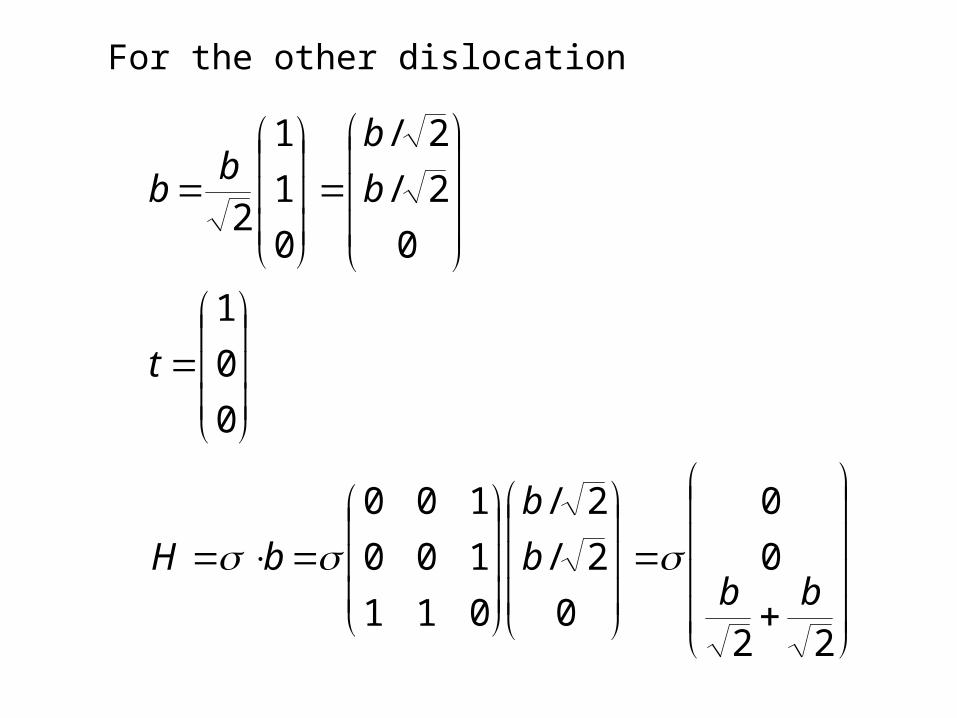
For the other dislocation
22
0
0
0
2/
2/
011
100
100
0
0
1
0
2/
2/
0
1
1
2
bbb
b
bH
t
b
bb
b
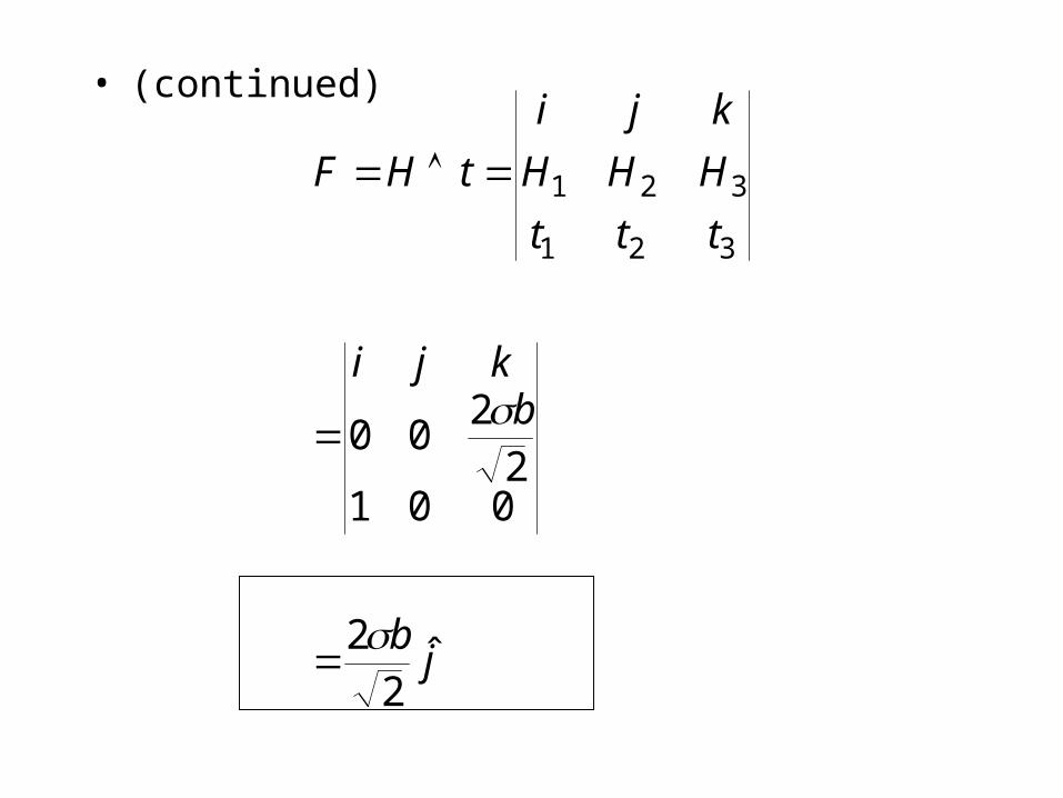
• (continued)
jb
bkji
ttt
HHH
kji
tHF
ˆ2
2
0012
200
321
321
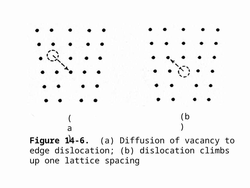
(b)(a)
Figure 14-6. (a) Diffusion of vacancy to edge dislocation; (b) dislocation climbs up one lattice spacing