for technical assistance call yale: push button deadbolt ... us/real living/installation... · lock...
TRANSCRIPT

Directions Components
Quick Start Instructions
Installation Instructions
Door Marker
Outside Escutcheon
Inside Escutcheon Assembly:
• Inside Mounting Plate
• Inside Escutcheon
• Battery Cover
4 AA Alkaline Batteries
Bolt
Strike Plate
Screw Pack (7 screws)
2 Keys
1. Install bolt in door.
NOTE: The bolt must be in a retracted position when installing the lockset.
Attach with two (2) M4 x 25.4mm screws supplied.
2. Install strike on the door frame.
3. Route the cable through 2-1/8" diameter hole.
NOTE: Cable must go under bolt and through.
See Detail A.
4. Insert outside escutcheon while routing cable through inside mounting plate’s 1/2" hole; insert mounting plate “tongue” into bottom slot of out side escutcheon.
5. Secure inside mounting plate to outside assembly using (2) M6 x 59.5mm pan head machine screws.
Do not over-tighten.
6. Attach cable assembly to the inside escutcheon printed circuit board (See Detail B above).
CAUTION:
Use care when assembling to ensure that the cable lies against the back recessed area of the inside escutcheon.
Position and bend the cable, using the harness clip as shown in Detail B to prevent binding when installing the escutcheon over the mounting plate.
7. Slide inside escutcheon over mounting plate.
8. Install and secure using (3) M6 x 9.5mm pan head machine screws through the battery housing into the mounting plate.
9. Insert four (4) AA alkaline batteries. The lock responds with a series of beeps and flashes.
Note: Refer to programming instructions prior to completion of step 10.
10. Install battery cover and tighten Phillips head screw.
Tools Needed � Phillips #2 screwdriver � 2-1/8" (54mm) hole saw � 1" (26mm) boring bit � 7/64" (2.5mm) drill bit � Chisel & hammer
Yale Real LivingPush Button Deadbolt Quickstart Guide
An ASSA ABLOY Group brand
P/N
AY
RD
210-
INS
T-Q
UK
Rev
B
™
For Technical Assistance call Yale: 1-800-810-WIRE (9473).
4
3
Detail A
Inside Mounting Plate
Inside Mounting Plate Inside Escutcheon
Outside Escutcheon
Battery Cover
5
7
8
10Cable
6
See Detail B
9
1
2
For more information go to: www.yalerealliving.com
(2) M4 x 25.4mm[8-32 x 1"] Flat Head
Combination Screws
(2) M4 x 25.4mm[8-32 x 1"] Flat HeadCombination Screws
(2) M6 x 59.5mm[15/64 x 2-11/32"]
Pan Head Machine Screws
(3) M4 x 8mm[8-32 x 5/16"]
Pan Head Screws
Harness clip
Route cable as indicated - do not cover hole
Detail B
An ASSA ABLOY Group brand
Open Door With PIN Code
For Technical Assistance call Yale: 1-800-810-WIRE (9473).
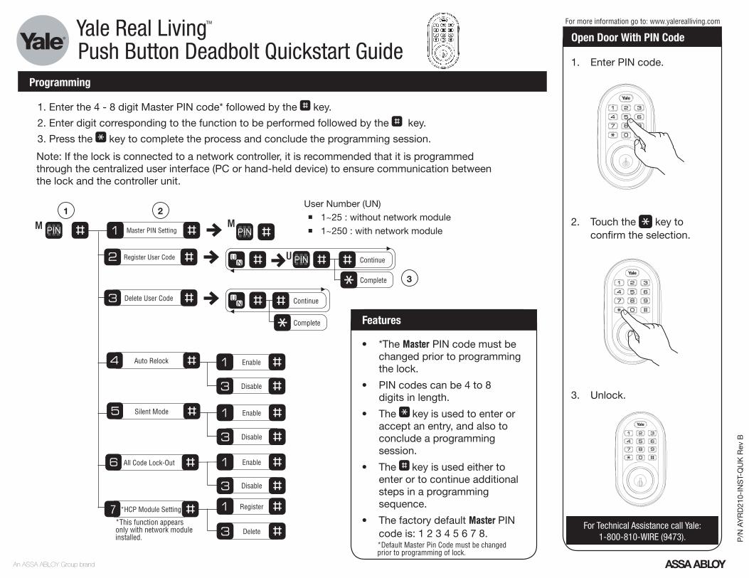
Programming
1. Enter PIN code.
2. Touch the key to confirm the selection.
3. Unlock.
User Number (UN) � 1~25 : without network module
� 1~250 : with network module
1. Enter the 4 - 8 digit Master PIN code* followed by the key.
2. Enter digit corresponding to the function to be performed followed by the key.
3. Press the key to complete the process and conclude the programming session.
Note: If the lock is connected to a network controller, it is recommended that it is programmed through the centralized user interface (PC or hand-held device) to ensure communication between the lock and the controller unit.
For more information go to: www.yalerealliving.comYale Real LivingPush Button Deadbolt Quickstart Guide
• *The Master PIN code must be changed prior to programming the lock.
• PIN codes can be 4 to 8 digits in length.
• The key is used to enter or accept an entry, and also to conclude a programming session.
• The key is used either to enter or to continue additional steps in a programming sequence.
• The factory default Master PIN code is: 1 2 3 4 5 6 7 8.
Features
M Master PIN Setting
Register User Code
1 2M
3
Delete User Code
Enable
Disable
Enable
Disable
All Code Lock-Out
Register
Delete
*HCP Module Setting
Enable
Disable
Auto Relock
Silent Mode
7
Complete
ContinueU
Complete
Continue
*This function appears only with network module installed. P
/N A
YR
D21
0-IN
ST-
QU
K R
ev B
™
*Default Master Pin Code must be changed prior to programming of lock.