for kingfisher cp-30 rtus version 4.1 · 1. introduction . toolbox plus user manual 4.1.0 page 8 ....
TRANSCRIPT

For Kingfisher CP-30 RTUs Version 4.1.0

Toolbox PLUS User Manual 4.1.0 Page 2
Document Information Copyright © 2007-2016 Servelec Technologies Pty Ltd. ABN 35 006 805 910
Web: http://www.servelec-semaphore.com/
Email: [email protected]
Kingfisher, Kingfisher PLUS and Toolbox PLUS are trademarks of Servelec Technologies. ISaGRAF is a trademark of ICS Triplex ISaGRAF Inc. All other product names are trademarks of their respective owners.
Doc rev: 7612

Toolbox PLUS User Manual 4.1.0 Page 3
Contents 1. Introduction ................................................................................................................. 7
1.1 Kingfisher RTUs .................................................................................................. 7
1.2 Toolbox PLUS ..................................................................................................... 7
1.3 Firmware ............................................................................................................. 8
2. Software Installation .................................................................................................... 9
2.1 Full Install ............................................................................................................ 9
2.2 Software Updates .............................................................................................. 11
2.3 Release Notes ................................................................................................... 11
3. Navigation ................................................................................................................. 12
3.1 Software Layout ................................................................................................ 12
3.2 Menu Bar ........................................................................................................... 13
3.3 Multiple Ways to Select a Menu......................................................................... 16
3.4 Workspace ........................................................................................................ 17
3.5 User Interface Elements .................................................................................... 19
4. Projects, Groups and RTUs ...................................................................................... 20
4.1 Overview ........................................................................................................... 20
4.2 Creating a Project .............................................................................................. 20
4.3 Grouping RTUs ................................................................................................. 20
4.4 Adding RTUs ..................................................................................................... 21
4.5 Renaming .......................................................................................................... 21
4.6 Project Properties .............................................................................................. 21
5. RTU Configuration .................................................................................................... 23
5.1 Overview ........................................................................................................... 23
5.2 Add Modules ..................................................................................................... 23
5.3 RTU Properties .................................................................................................. 26
5.4 Protocols ........................................................................................................... 27
5.5 Ports .................................................................................................................. 45
5.6 Routes ............................................................................................................... 53
5.7 Phone Numbers ................................................................................................ 60
5.8 Programs ........................................................................................................... 61
5.9 Redundancy Settings ........................................................................................ 63
5.10 Module Properties ............................................................................................. 64
6. Dictionary .................................................................................................................. 70
6.1 Variables ........................................................................................................... 70
6.2 Adding Variables ............................................................................................... 72
6.3 Editing Variables ............................................................................................... 75

Toolbox PLUS User Manual 4.1.0 Page 4
6.4 Exporting and Importing Variables ..................................................................... 77
7. Maps ......................................................................................................................... 78
7.1 Viewing RTU Locations ..................................................................................... 78
7.2 Positioning an RTU............................................................................................ 79
7.3 Finding an RTU ................................................................................................. 79
8. ISaGRAF .................................................................................................................. 80
8.1 ISaGRAF Overview ........................................................................................... 80
8.2 Function Blocks ................................................................................................. 81
8.3 Getting Started .................................................................................................. 81
8.4 How Logic is Executed ...................................................................................... 90
8.5 ISaGRAF Tips ................................................................................................... 92
8.6 ISaGRAF Variable Types .................................................................................. 93
8.7 ISaGRAF Constants .......................................................................................... 96
8.8 ISaGRAF Reserved Names ............................................................................... 97
8.9 ISaGRAF Licensing Details ............................................................................... 98
9. ISaGRAF Function Blocks ......................................................................................... 99
9.1 Kingfisher Protocol .......................................................................................... 102
9.2 DNP3 Protocol ................................................................................................. 110
9.3 Modbus Protocol ............................................................................................. 119
9.4 Allen Bradley DF1 Protocol .............................................................................. 121
9.5 HART Protocol ................................................................................................ 123
9.6 SNMP Client Protocol ...................................................................................... 125
9.7 SNMP Trap Protocol ........................................................................................ 131
9.8 SNMP RMS Trap Protocol ............................................................................... 133
9.9 User Defined Protocol ..................................................................................... 135
9.10 SMS Protocol .................................................................................................. 136
9.11 VRRP Protocol ................................................................................................ 138
9.12 General Communications ................................................................................ 139
9.13 Event Logging ................................................................................................. 145
9.14 RTU System Data ........................................................................................... 147
9.15 Maths and Logic .............................................................................................. 154
9.16 PID Controller .................................................................................................. 162
9.17 Gas Flow Calculations ..................................................................................... 164
9.18 Obsolete Function Blocks ................................................................................ 175
10. ISaGRAF - Logic Examples .................................................................................. 176
10.1 Detecting Modules ........................................................................................... 176
10.2 Scaling ............................................................................................................ 176
10.3 Hours ON ........................................................................................................ 177
10.4 Counting Pulses .............................................................................................. 177

Toolbox PLUS User Manual 4.1.0 Page 5
10.5 Flow Totalisation ............................................................................................. 177
10.6 Daily Totals ..................................................................................................... 178
10.7 Exception Reporting Digitals ............................................................................ 179
10.8 Exception Reporting Analog Variables............................................................. 180
10.9 Event Logging ................................................................................................. 181
10.10 Logic Examples – Polling .......................................................................... 183
10.11 Modbus Protocol ....................................................................................... 185
10.12 Allen Bradley Protocol ............................................................................... 188
10.13 Sending an SMS ....................................................................................... 189
11. Redundancy .......................................................................................................... 192
11.1 Redundant Processors .................................................................................... 192
11.2 Redundant Power Supplies ............................................................................. 196
11.3 Redundant Communications ........................................................................... 196
11.4 Redundant PCs ............................................................................................... 198
12. Security ................................................................................................................. 200
12.1 Overview ......................................................................................................... 200
12.2 Security Policies .............................................................................................. 200
12.3 Project Tamper Detection ................................................................................ 202
12.4 Security Policy Distribution Scenarios.............................................................. 202
12.5 Securing a Project ........................................................................................... 206
12.6 Unsecuring a Project ....................................................................................... 207
12.7 Role Based Access Control ............................................................................. 208
12.8 Roles and Permissions .................................................................................... 209
12.9 Managing Users .............................................................................................. 209
12.10 Managing Roles ........................................................................................ 211
12.11 Managing a Secured RTU ......................................................................... 214
12.12 Maintaining Security .................................................................................. 216
13. Local Backups ....................................................................................................... 218
13.1 Overview ......................................................................................................... 218
13.2 Making a Backup ............................................................................................. 218
13.3 Restoring a Project .......................................................................................... 220
14. Connecting to an RTU ........................................................................................... 221
14.1 Cables ............................................................................................................. 221
14.2 LAN Port Setup ............................................................................................... 222
14.3 Connection Parameters ................................................................................... 224
14.4 Discovery ........................................................................................................ 225
14.5 RTU Restart .................................................................................................... 227
14.6 Factory Reset .................................................................................................. 228
15. Download .............................................................................................................. 229

Toolbox PLUS User Manual 4.1.0 Page 6
15.1 Overview ......................................................................................................... 229
15.2 Downloading Configurations ............................................................................ 229
15.3 Downloading Firmware .................................................................................... 232
16. Viewing Data ......................................................................................................... 234
16.1 Status .............................................................................................................. 234
16.2 Event Logs ...................................................................................................... 238
16.3 RTU Time Zone ............................................................................................... 240
16.4 Communications .............................................................................................. 242
17. Appendices ........................................................................................................... 247
17.1 Glossary .......................................................................................................... 247
17.2 Creating Variables Using Excel ....................................................................... 248
17.3 Protocol Support .............................................................................................. 252
17.4 RTU Variables ................................................................................................. 254

1. Introduction
Toolbox PLUS User Manual 4.1.0 Page 7
1. Introduction
1.1 Kingfisher RTUs A Remote Telemetry Unit (RTU) is a device that contains processing and communications equipment and is often located in a remote place. Kingfisher RTUs can interface to switches, relays and sensors, and connect to other intelligent devices via a wide range of supported protocols.
Kingfisher RTU features include:
• A wide range of modular analog and digital I/O
• Non-volatile event logging
• Support for diverse communications media – data radios, dialup and cellular modems, leased line, Ethernet and more…
• PLC-like logic processing utilizing all IEC 61131-3 languages
• Live logic debugging
• Support for multiple protocols in the same installation: Kingfisher, Modbus, DNP3 (with secure authentication), SNMP, Allen Bradley DF1 and more…
• Support for redundant power supplies, redundant processors and redundant communications – to maximise system availability
1.2 Toolbox PLUS This manual describes Toolbox PLUS Version 4.1.0. Toolbox PLUS is a Windows based software application used to configure and monitor modular Kingfisher PLUS RTUs using the CP-30 processor
The manual also covers the basic usage of ISaGRAFTM, which is used for logic entry and debugging. Further details may be found in the ISaGRAF on-line help.
Note: This version of Toolbox PLUS requires Windows 7 or later. Windows XP and earlier are not supported.
Note: For Kingfisher modular RTUs based on the earlier CP-12 or PC-1 processors, the G3 standalone RTU, and the LP-3 low power RTU, Toolbox 32 software is used. This manual does not cover this software.

1. Introduction
Toolbox PLUS User Manual 4.1.0 Page 8
1.3 Firmware Firmware is the software that is built into the RTU processor modules. Toolbox PLUS and the RTU firmware work closely together, so it is important that compatible versions are used.
This version of Toolbox PLUS should be used with CP-30 processors running firmware Version 4165 or later.
It may also be used with RTU processors with earlier firmware, provided that you only work with existing projects. Newly created projects may contain features which are not supported by the older firmware. Be aware also that some of the firmware features described in this manual may not be supported in earlier firmware, or may work differently.
Note: Certain features described in this manual may require firmware that is later than version 4165. These are identified by the note: “(requires recent firmware)”.
Firmware updates are available from the Servelec Technologies website (http://helpdesk.servelec-semaphore.com/), and may be installed using Toolbox PLUS (see Downloading Firmware). Check the firmware release notes to determine whether the feature you require is implemented in that release.

2. Software Installation
Toolbox PLUS User Manual 4.1.0 Page 9
2. Software Installation
2.1 Full Install Toolbox PLUS, ISaGRAF Workbench, and various other files and utilities are normally supplied on a USB flash drive or CD. If you purchased an ISaGRAF license then you should also have received a USB license key, or “dongle”. (ISaGRAF can be used in trial mode for up to 30 days without the license key.)
It is recommended that you close all other programs before starting the installation. You may also need to temporarily disable anti-virus programs.
During installation, you may be prompted to restart your computer. This can be delayed until after all applications have been installed.
Insert the Toolbox PLUS USB flash drive or CD into the PC.
Open the drive in Windows Explorer and double click on the file: autorun.exe
The installation menu should be displayed.
Click the Sentinel USB Driver button on the installation menu and follow the prompts to install it on your computer.
This driver provides support for the ISaGRAF USB protection key.
2. Software Installation
Toolbox PLUS User Manual 4.1.0 Page 10
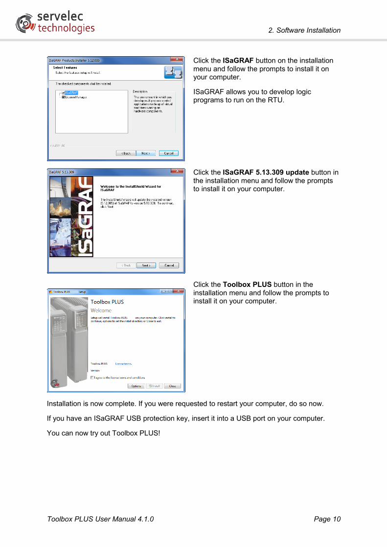
Click the ISaGRAF button on the installation menu and follow the prompts to install it on your computer.
ISaGRAF allows you to develop logic programs to run on the RTU.
Click the ISaGRAF 5.13.309 update button in the installation menu and follow the prompts to install it on your computer.
Click the Toolbox PLUS button in the installation menu and follow the prompts to install it on your computer.
Installation is now complete. If you were requested to restart your computer, do so now.
If you have an ISaGRAF USB protection key, insert it into a USB port on your computer.
You can now try out Toolbox PLUS!

2. Software Installation
Toolbox PLUS User Manual 4.1.0 Page 11
2.2 Software Updates Keep your copy of Toolbox PLUS up to date by downloading and installing updates as they become available.
The latest version of Toolbox PLUS can be downloaded from the Servelec Technologies website (http://helpdesk.servelec-semaphore.com/). Note that the download package contains Toolbox PLUS software only; you will need to already have installed ISaGRAF 5.13.309 from a Toolbox PLUS USB flash drive or CD.
To install an update, simply double click on the downloaded executable file. This will start the Toolbox PLUS installer.
2.3 Release Notes Release notes are supplied with each Toolbox PLUS release. These describe the changes made in each version, and any other special instructions that may be required. Be sure to read these before installing or using Toolbox PLUS.

3. Navigation
Toolbox PLUS User Manual 4.1.0 Page 12
3. Navigation
3.1 Software Layout Toolbox PLUS employs a layout similar to many Windows applications. The Workspace and many of the menus are contextual meaning the display will vary according to what is currently selected.
Title Bar: Displays the name of the active project (if open) and the Toolbox PLUS program version
Menu Bar & Tool Bar:
Allows access to all Toolbox PLUS commands. Note: some commands are only available when an RTU is selected in the navigation pane
Status Bar: Displays information about the progress or result of an action.
Stacked Menu Bar:
Selects between broad categories of information to be displayed in the Workspace:
Navigation Pane:
Displays the hierarchy of projects, groups and RTUs. Clicking on an item displays relevant information in the Workspace; double clicking allows the item’s properties to be viewed and edited.
Workspace: Displays variable information depending on the currently selected items in the navigation pane and stacked menu bar. This may include system configuration, modules, variables and event logs
Title Bar Tool Bar
Workspace
Menu Bar
Status Bar
Navigation Pane
Stacked Menu Bar

3. Navigation
Toolbox PLUS User Manual 4.1.0 Page 13
3.2 Menu Bar The commands available from the Menu bar options – File, Edit, Tools and Help are described below. Some commands can be accessed using shortcut keys. These are listed alongside the Menu Bar commands shown below.
3.2.1 File Menu
New: Allows a new project, group, RTU, module or variable to be created.
Note the menu items are disabled if not applicable to the current selection.
Open: Opens an existing project.
Close: Closes selected project
Save: Saves selected project
Save As: Allows project to be saved with a new name and in a new location.
Export: Allows an entire project to be migrated to another computer using the To File or To Email option, or the projects dictionary and symbol information to be exported to Excel for editing.
Import: Allows dictionary variables to be imported from an Excel spreadsheet. The format of the spreadsheet must be the same as the spreadsheet created using the Export To Excel function above.
Recent Projects: Recently opened projects are listed here.
Exit: Closes Toolbox PLUS program.

3. Navigation
Toolbox PLUS User Manual 4.1.0 Page 14
3.2.2 Edit Menu
Cut: Copies the selected RTU configuration and then deletes it from the project.
Copy: Copies the selected RTU configuration.
Paste: Pastes the last copied RTU configuration into the selected group or project.
Rename: Allows the name of a project, group or RTU to be changed. Names can include spaces, hyphens ( - ), underscores ( _ ), commas ( , ) and periods ( . ).
Delete: Deletes the selected group, RTU or module (modules are selected in the workspace). Note projects cannot be deleted, only closed. If you wish to delete a project, Windows Explorer is required.
Properties: Allows the settings for a project, group, RTU or module to be changed.
3.2.3 Tools Menu
Connection: Contains settings for how to communicate with the selected RTU. Only available when a project, group or RTU is selected. See Connection Parameters.
Discovery: Detects all RTUs on the same subnet as the PC Ethernet port(s), or connected to the PC’s serial port.
ISaGRAF: Launches the ISaGRAF logic editor for the selected RTU.
Build: compiles the configuration and ISaGRAF programs for the selected RTU.
Download: Downloads the compiled Configuration and/or Logic (and optionally the complete project for later retrieval) to the selected RTU. Toolbox PLUS will automatically compile the configuration and/or logic if required before downloading. See Download for more details.
Download > Firmware: Downloads new CP-30 or MC-31 firmware. See Download for more details.
Upload > Configuration: Retrieves the

3. Navigation
Toolbox PLUS User Manual 4.1.0 Page 15
current configuration from the connected RTU and creates a new project from it. This project will contain module definitions and settings, but not any user logic running on the RTU, unless you chose the Configuration, Logic and Project option when the configuration was downloaded to the RTU.
Upload > Service Report: Requests the RTU to prepare a diagnostic service report (requires firmware version 2918 or later). If you encounter a problem with the RTU, our support team may ask you to email the service report that the problem can be diagnosed more quickly.
Restart: Restarts the selected RTU.
Advanced > Download MC-30 firmware: Used to download firmware to an MC-30 module.
Status: Displays live status information for the selected RTU. Multiple module status windows can be viewed at the same time for the one RTU.
3.2.4 Help Menu
Toolbox PLUS help: Displays the Toolbox PLUS online help.
Show Toolbox PLUS log files: This will open the folder where Toolbox PLUS stores diagnostic logs during operation. If you encounter a problem using Toolbox PLUS, our support team may ask you to email the files in this folder so that the problem can be diagnosed more quickly.
About Toolbox PLUS: Displays Toolbox PLUS version number and other information.

3. Navigation
Toolbox PLUS User Manual 4.1.0 Page 16
3.3 Multiple Ways to Select a Menu In many cases there are multiple ways to select commonly used functions. The examples below show different ways to edit the RTU properties.
Via Menu Bar: Select the RTU name in the navigation pane.
Then select Edit Properties.
Via Right-click menu: Right-click the RTU name in navigation pane.
Then select Properties.
Via Double-click: Double-click the RTU name in the navigation page
Via Keyboard Shortcut: Select the RTU name in the navigation pane and press Alt+Enter.

3. Navigation
Toolbox PLUS User Manual 4.1.0 Page 17
3.4 Workspace The workspace area is context-specific, meaning that it will change according to what is currently selected in the navigation pane and stacked menu bar.
The various Workspace displays are shown below:
Default View
Displayed when Toolbox PLUS is first started or Projects is selected in the navigation pane.
The Recent Projects that were opened in the past can be opened again.
View RTUs
When a project name is selected in the navigation pane, the RTUs and RTU groups in that project are displayed in the workspace.
View Modules
When an RTU name is selected in the navigation pane, the RTU’s modules are displayed in the workspace.
This view allows module properties to be configured (double-click on any module).
For more information please see the topic RTU Configuration - Module Properties.

3. Navigation
Toolbox PLUS User Manual 4.1.0 Page 18
View Dictionary
When an RTU name is selected in the navigation pane, the RTU’s dictionary is displayed in the workspace.
This view allows variables to be edited (double-click on an existing variable) or created (select the New button).
For more information see Dictionary.
Event Log
When an RTU name is selected in the navigation pane, the RTU’s event log is displayed in the workspace.
This view allows event logs to be retrieved from an RTU, filtered, exported (saved) and cleared.
For more information see View - Event Logs.
Comms Analyzer
When an RTU name is selected in the navigation pane, a list of received and transmitted communications messages is displayed in the workspace.
This is useful for diagnosing communications issues. See Comms Analyzer.
Map
When an RTU name is selected in the navigation pane, the workspace displays the RTU location on a map, if it has been set.
For more information see Maps
3. Navigation
Toolbox PLUS User Manual 4.1.0 Page 19
3.5 User Interface Elements Toolbox PLUS employs certain non-standard graphical user interface (GUI) controls. These are described below.
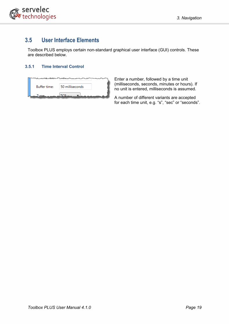
3.5.1 Time Interval Control
Enter a number, followed by a time unit (milliseconds, seconds, minutes or hours). If no unit is entered, milliseconds is assumed.
A number of different variants are accepted for each time unit, e.g. “s”, “sec” or “seconds”.

4. Projects, Groups and RTUs
Toolbox PLUS User Manual 4.1.0 Page 20
4. Projects, Groups and RTUs
4.1 Overview In Toolbox PLUS, a system is organised into the following hierarchy:
• A project contains all settings for the entire system. This may encompass many RTUs spread across multiple sites.
• The project may optionally define groups of RTUs which share something in common, e.g. they might be located at the same site.
• An RTU represents a physical RTU – a rack of modules, including at least one CP-30 processor. The RTU has various properties that can be set, and various status items that can be viewed.
• An RTU consists of the configured set of modules. Like RTUs, individual modules have properties that can be set, and status items that can be viewed.
Projects and groups are only used by Toolbox PLUS to organise how the information is displayed and saved. Project and group names are not downloaded into the RTU.
All settings for a project (including details for any RTUs defined therein) are saved to a project folder on the PC’s file system. The name and location of this folder is specified when you first save the project.
4.2 Creating a Project A new project must be created before any RTU configurations can be created.
Create New Project
Select New Project
Alternatively, right click on Projects in the navigation pane and select New Project.
You can also create a project by clicking on the Start a new project link on the default workspace screen.
4.3 Grouping RTUs When configuring multiple RTUs, they can be kept in groups. Grouping similar RTUs can simplify large project layouts, for example, outstations and master RTUs may be grouped.

4. Projects, Groups and RTUs
Toolbox PLUS User Manual 4.1.0 Page 21
Create New Group
Select the project name in the navigation pane, then select New Group.
Alternatively, right-click on the project name and select New Group.
4.4 Adding RTUs RTUs can be added directly into a project or added into a project group.
Create New RTU
Select the project or group name in the navigation pane, then select New RTU
Alternatively, right-click on the project or group name and select New RTU.
Select a numeric address for the RTU (1-65520) and click OK. A minimal RTU configuration will be created containing power supply and processor modules/cards.
4.5 Renaming The new project, group and RTUs can be renamed.
Rename Project, Group or RTU
Select the project, group or RTU in the navigation pane, then select Edit Rename.
Alternatively, right-click on the name and select Rename.
4.6 Project Properties A project has certain properties that can be set. These relate to the overall project, and do not affect the operation of any RTU.

4. Projects, Groups and RTUs
Toolbox PLUS User Manual 4.1.0 Page 22
View/Edit Project Properties
Right-click on the name and select Properties (or just double-click the Project name).
Name: (up to 255 characters) a descriptive name for the project can be entered here.
Names can include spaces, hyphens (-), underscores (_), commas (,) and periods (.). Other special characters are not permitted.
If no name is entered then you will be prompted for one when the project is saved to disk.
Location: This link will open the project folder in Windows Explorer.
Note: This link is for reference only. Do not change or open any files in the project folder.

5. RTU Configuration
Toolbox PLUS User Manual 4.1.0 Page 23
5. RTU Configuration
5.1 Overview The primary function of Toolbox PLUS is to configure one or more Kingfisher RTUs so that they can perform the required functions. This involves specifying:
• Types of power supply, processor, I/O and communications modules
• Communications protocols to use (Modbus, DNP3, etc.)
• Routes, which specify the ports to use to communicate with other RTUs or devices
• Protocol and I/O points of the required types (boolean, integer, etc.)
• Logic processing functions, which are entered using ISaGRAF (ladder logic, structured text, etc.)
• Other settings and options (addresses, timeouts, security, etc.)
These settings are saved to a project file on the PC, then compiled into a form which can be downloaded to each RTU’s processor module.
5.2 Add Modules
5.2.1 Backplanes and Racks
Physically, all modules in a modular RTU are installed on a backplane. A backplane has 2, 4, 6 or 12 slots.
An RTU’s backplanes are organised into between one and four linked racks. Each rack supports up to 16 modules and may contain either one or two linked backplanes. Therefore the maximum number of modules per RTU is 64.
The slot numbers for a given backplane depend on the type of backplane and the rack number. The rack number is configured using DIP switches on the backplane. Rack #1 always contains slots 1-16, Rack #2 contains slots 17-32, Rack #3 contains slots 33-48 and Rack #4 contains slots 49-64.
Rack #1 will normally consist of one of the following backplane configurations:
Backplane Type Rack #1 Slot Numbers 2-slot powered 1 2 4-slot powered 1 2 3 4 6-slot powered 1 2 3 4 5 6 4-slot 13 14 15 16 4-slot 1 2 3 4 6-slot 1 2 3 4 5 6 12-slot 1 2 3 4 5 6 7 8 9 10 11 12 12-slot + 4-slot 1 2 3 4 5 6 7 8 9 10 11 12 13 14 15 16

5. RTU Configuration
Toolbox PLUS User Manual 4.1.0 Page 24
To accommodate additional modules, up to three further racks can be connected. For example, Rack #2 would normally consist of one of the following backplane configurations:
Backplane Type Rack #2 Slot Numbers 4-slot 29 30 31 32 4-slot 17 18 19 20 6-slot 17 18 19 20 21 22 12-slot 17 18 19 20 21 22 23 24 25 26 27 28 12-slot + 4-slot 17 18 19 20 21 22 23 24 25 26 27 28 29 30 31 32
Note that
• The powered backplanes (Error! Unknown document property name.) include an integrated power supply, so a PS-xx power supply module is not required. (An external 12V DC supply is required.) These backplanes are intended for small, single-rack systems, although additional passive backplanes (Error! Unknown document property name.) can still be connected.
• The 4-slot passive backplane version 3.3 and higher can be configured (via DIP switches) to have slot numbers 1-4 or 13-16. Earlier revisions have slots numbered 13-16.
• The symbol denotes a cable link between backplanes.
Toolbox PLUS does not distinguish between physical backplanes – it treats the RTU as a single unit with 64 slots, numbered 1-64. It is important, however that each module’s slot number be entered correctly. For example, in a small RTU with a single early revision 4-slot passive backplane, the entered slot numbers should be in the range 13-16, not 1-4. Likewise, if two 12-slot backplanes are chained together, the available slot numbers will be 1-12 and 17-28, not 1-24.
For more information, refer to the Kingfisher PLUS+ Hardware Reference Manual, available for download from the Servelec Technologies website.
5.2.2 Adding Modules
When you first create an RTU in Toolbox PLUS, it will contain two modules by default: a power supply module in backplane slot 1 and a processor module in slot 2.
Modules can now be added or moved to build up the desired RTU layout.
For a modular RTU, module types that can be added include:
• Power supply modules (PS-1x/PS-2x). Multiple power supplies can be included to provide redundancy.
• Processor modules (CP-30). At least one CP-30 must be present. A second CP-30 can be included, for redundancy. If two CP-30s are used then one must be in an even slot and the other in an odd slot.
• Communications modules (MC-31, or its predecessor, MC-30). These provide additional Ethernet or serial communications ports (up to 3 ports per module)
• I/O modules (AI-1/4, AI-10, AO-2, AO-3, DI-1, DI-10, DI-5, DO-1, DO-2/5/6, IO-2, IO-3, IO-4, IO-5), which provide analog/digital inputs and outputs.
5. RTU Configuration
Toolbox PLUS User Manual 4.1.0 Page 25
Toolbox PLUS will automatically create variables in the dictionary corresponding to all the I/O points in each power supply or I/O module.
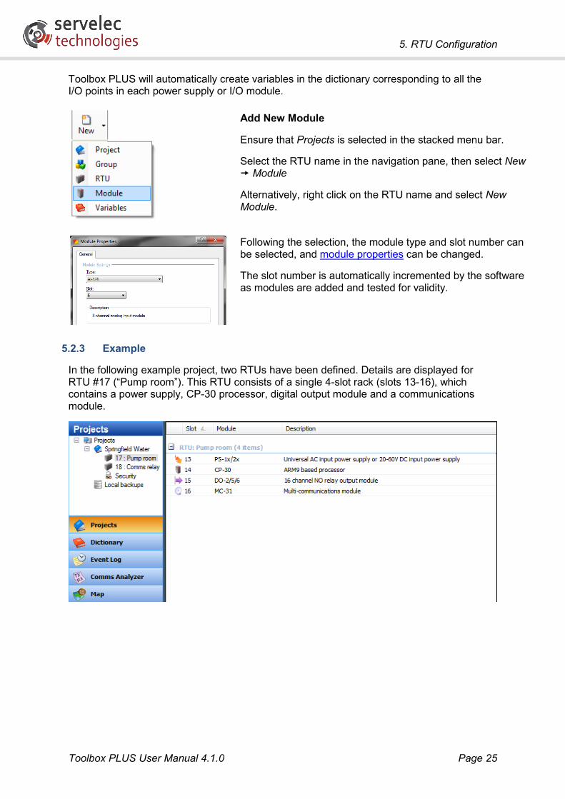
Add New Module
Ensure that Projects is selected in the stacked menu bar.
Select the RTU name in the navigation pane, then select New Module
Alternatively, right click on the RTU name and select New Module.
Following the selection, the module type and slot number can be selected, and module properties can be changed.
The slot number is automatically incremented by the software as modules are added and tested for validity.
5.2.3 Example
In the following example project, two RTUs have been defined. Details are displayed for RTU #17 (“Pump room”). This RTU consists of a single 4-slot rack (slots 13-16), which contains a power supply, CP-30 processor, digital output module and a communications module.

5. RTU Configuration
Toolbox PLUS User Manual 4.1.0 Page 26
5.3 RTU Properties The RTU Properties menu allows the global settings of each RTU to be modified. The settings are grouped into a number of tabs.
The General tab contains descriptive settings (name, location, etc.) and protocol addressing information.
Edit RTU Properties
Right-click on the name and select Properties (or just double-click the Project name).
Address: (1-65520) Each RTU must have a unique address. If the RTU is connected to a "series 2" network (containing CP12/LP3/G3 based RTUs) then addresses should be set in the range 1-249.
System ID: (00 to FF Hex) The communications sync character used to screen incoming Kingfisher protocol messages. An RTU will only respond to messages that have the same sync character as this System ID. It is recommended that the AE default be used except when configuring an RTU to relay radio messages as detailed in the topic RTU Configuration - Routes, Relaying Radio Messages.
Name: (0 to 64 characters) Name of the RTU.
Description: (0 to 255 characters) Description of the RTU.
Time zone: (optional) If a time zone is selected, all date and time values received from the RTU will be displayed using this time zone. If set to “unspecified”, RTU times are not assumed to be in any particular time zone, and no corrections will be applied. See RTU Time Zone for more information.
Longitude, Latitude: (optional) The geographical location of the RTU. Please see the chapter - Maps.
Maximum Event Logs: (0-100,000; default = 10,000) The maximum number of event logs to maintain in Flash memory. Once the maximum limit is reached, the oldest event logs are overwritten. This value may be rounded up to a multiple of the internal block size (depending on firmware version).

5. RTU Configuration
Toolbox PLUS User Manual 4.1.0 Page 27
5.4 Protocols A protocol is a set of communication commands used to communicate with a device. The RTU supports the following protocols:
Protocol Type Purpose Port type Kingfisher slave, master RTU configuration and management
Data point status and event transfer Ethernet, serial
Modbus/TCP slave, master Data point status transfer Ethernet Modbus/RTU slave, master Data point status transfer Serial Modbus/ASCII slave, master Data point status transfer Serial DNP3 slave, master Data point status and event transfer Ethernet, serial Allen Bradley master Data point status transfer Serial SNMP Client master Retrieve RTU status information Ethernet SNMP Slave slave Report RTU status information Ethernet SNMP Trap slave, master Send or receive RTU status notifications Ethernet User Defined peer Send or receive raw serial messages Serial HART master Data point status transfer HART option card SMS master Send text messages via 3G router Ethernet NTP master Set RTU time from NTP server Ethernet VRRP slave, master Allow multiple RTUs to emulate a single IP
network gateway, for redundancy Ethernet (CP-30 Port 1 only)
Terminal server peer Allow arbitrary data to be transparently passed between an Ethernet and a serial port
Ethernet, serial (Option I only)
In the above table, if the RTU implements a “master” protocol then it can initiate messages to another device. These messages are typically triggered when appropriate ISaGRAF custom function blocks are executed. Conversely, when the RTU acts as a “slave” it responds to incoming requests.
In the above table, a “serial” port type refers to any serial-based option card, including RS232/422/485 (Option I), Fibre (Option F), Dialup (Option D), Line (Option L) and Spread Spectrum Radio (Option R2/R3/R4).
For Ethernet (TCP/IP) based protocols, multiple protocols can generally operate simultaneously on the same physical Ethernet port. Messages are distinguished using the TCP or UDP “port numbers” built into TCP/IP. For example, DNP3 messages are normally directed to TCP/UDP port 20000, while Modbus/TCP messages use TCP port 502.
Serial ports can only be configured for a single protocol.
By default, only the Kingfisher protocol is enabled. To set up other protocols, you need to:
• Add the protocol to the RTU configuration. This causes the required driver software to be started when the configuration is downloaded to the RTU.
• Assign the protocol to the required ports. Toolbox PLUS validates all selections, and prevents you from assigning two different protocols to a serial port, for example. Note that the HART, VRRP protocols do not need to be assigned to a port as they operate using fixed ports.

5. RTU Configuration
Toolbox PLUS User Manual 4.1.0 Page 28
Add, Remove or Edit Protocol Right-click on the RTU name and select Properties (or just double-click the RTU name).
Select the Protocols tab
Select the Add button to add a protocol OR select an existing protocol to edit or remove and then select the Edit or Remove button
Note: multiple protocols can be selected and added at the same time by using the CTRL or SHIFT keys and selecting the relevant protocol(s) with the mouse.
The following sections briefly describe the available protocols
5.4.1 Kingfisher Protocol
Overview
Kingfisher Protocol is the “native” protocol for Kingfisher RTUs. By default, it is enabled on all Ethernet and serial ports.
This protocol allows data to be transmitted through multi-level networks. That is, messages to a remote RTU can be automatically forwarded via intermediate RTU(s).
The protocol supports the transfer of event logs (historical data), as well as real-time data.
Kingfisher Protocol is also used by Toolbox PLUS for querying the status of an RTU, e.g. checking firmware version, number of logged events, etc.

5. RTU Configuration
Toolbox PLUS User Manual 4.1.0 Page 29
The RTU implements both the slave and master ends of the protocol, so an RTU can be set up as a concentrator, which can poll outstation RTUs for events and then be polled by Toolbox PLUS or a SCADA system. When operating as a master, the RTU generates Kingfisher messages using custom ISaGRAF function blocks.
Kingfisher Variables
In order to transfer data using the Kingfisher Protocol, registers must be manually created in the Dictionary to hold the data:
• To store local data where they can be polled by another system, Local Kingfisher Registers need to be created. These have names of the form KFRn.
• To store data that have originated from another RTU, Network Kingfisher Registers should be created. These have names of the form KFrRn, where r is the RTU from which they originated.
The Kingfisher Protocol supports two types of polling (In this example RTU1 is polling RTU2):
• Direct polling: The KF_RX_DATA function block will copy RTU2’s local registers KFRn into network registers KF2Rn on RTU1.
• Indirect polling: The KF_NW_RX_DATA function block will copy RTU2’s network registers KF3Rn and KF4Rn (assuming RTU2 is set up to poll RTU3 and RTU4) into RTU1’s matching network registers KF3Rn and KF4Rn.
Port Types
The Kingfisher protocol is supported on all port types, except the HART option card.
For Ethernet ports, Kingfisher protocol uses UDP ports 473 and 4058.
5.4.2 Modbus
Overview
Modbus is a simple, widely used protocol which can transfer integer and boolean values. Modbus does not support the transfer of historical event data. The Kingfisher RTU supports three Modbus variants:
• Modbus/RTU is used on serial lines, e.g. RS232, RS485
• Modbus/ASCII is also used on serial lines but it uses ASCII encoding, which is less efficient but can be easier to deal with in some systems
• Modbus/TCP uses Ethernet to transport the Modbus packets over a TCP/IP network. By default, TCP port 502 is used.
For each of these, the RTU supports both the master end (where the RTU initiates a request when the MODBUS custom ISaGRAF function block is executed), and the slave end (where the RTU responds to incoming requests).
For more details on the specific Modbus functions supported by the RTU, refer to the tables in the Protocol Support section.
Data Types
Modbus defines four types of data point:

5. RTU Configuration
Toolbox PLUS User Manual 4.1.0 Page 30
• Coils are single bit outputs
• Discretes are single bit inputs
• Holding registers are 16-bit output registers
• Input registers are 16-bit input registers
A Modbus device may have up to 65536 of each type of point. These are addressed using a 16-bit index (0-65535).
Modbus Variables
In order to transfer data using Modbus, variables must be created in the Dictionary to hold the data:
• To store local data where they can be polled by another system, Local Modbus Registers need to be created. These have names of the form MODCn (coil), MODDn (discrete), MODHn (holding) or MODIn (input).
• To store data that have originated from another RTU, Network Modbus Registers should be created. These have names of the form MODrCn (coil), MODrDn (discrete), MODrHn (holding) or MODrIn (input), where r is the RTU from which they originated.
Extended Addresses
Note that Modbus addresses are 8 bits long (1-254). When accessing Modbus variables on an RTU with an address greater than 255, be aware that only the least significant byte (lower 8 bits) of the RTU address will be used in Modbus messages.
For example, if you have slave RTUs with address 20 (0014h) and address 276 (0114h) on the same multi-drop network (e.g. Ethernet or RS-485), then you will not be able to poll both of them using Modbus, because the least significant byte of each address is the same. To rectify this you would need to change one of the addresses, or use different physical ports.

5. RTU Configuration
Toolbox PLUS User Manual 4.1.0 Page 31
Modbus Settings
Modbus/TCP has some additional settings that can be adjusted:
Modbus/TCP Settings
Right-click on the RTU name and select Properties (or just double-click the RTU name).
Select the Protocols tab
Select Modbus TCP from the protocols list and click Edit (or just double-click on Modbus TCP)
TCP port number: (1-65535, default=502) These settings allow the TCP port number used by Modbus/TCP to be changed. Different port numbers can be selected for master and slave operation.
5.4.3 DNP3
Overview
Distributed Network Protocol version 3 (DNP3) is a widely used telemetry protocol. It is more sophisticated than Modbus in that it supports:
• Polling for events (state changes) as well as current values (Class 0 data)
• Optional unsolicited reporting of state changes from slave to master, which reduces the amount of polling required
• Grouping events into classes (Class 1, 2 or 3) which can be selectively retrieved
• A richer set of data object types

5. RTU Configuration
Toolbox PLUS User Manual 4.1.0 Page 32
A Kingfisher RTU can act as a DNP3 Slave, a DNP3 Master or both. The RTU can respond to DNP3 messages (DNP3 Slave), initiate DNP3 messages using DNP3 function blocks (DNP3 Master) or forward DNP3 messages. DNP3 has various protocol settings that can be edited as detailed below.
Data Types
The following DNP3 data types are supported:
• Analog inputs are 32-bit integer (variations 1 and 3), 16-bit integer (variations 2 and 4) or 32-bit floating point (variation 5) input registers
• Analog outputs are 32-bit integer (variation 1) or 16-bit integer (variation 2) or 32-bit floating point (variation 3) output registers
• Binary inputs are single bit inputs (variations 1 and 2)
• Binary outputs are control outputs (variations 1 and 2). Single bit pulse on/off and latch on/off operations are supported, as well as paired trip/close operation, where one physical output “trips” the device (turns it off) and the other “closes” it (turns it on)
• Binary counters are 32-bit integer (variations 1 and 5), 16-bit integer (variations 2 and 6) counter inputs
• Frozen counters are copied from the associated binary counter when a DNP3 “freeze” command is received
DNP Variables
In order to transfer data using DNP3, variables must be created in the Dictionary to hold the data:
• To store local data where they can be polled by another system, Local DNP3 Registers need to be created. These have names of the form DNPAIn (analog input), DNPAOn (analog output), DNPBIn (binary input), DNPBOn (binary output), DNPBCn (binary counter) or DNPFCn (frozen counter).
• To store data that have originated from another RTU, Network DNP3 Registers should be created. These have names of the form DNPrAIn (analog input), DNPrAOn (analog output), DNPrBIn (binary input), DNPrBOn (binary output), DNPrBCn (binary counter) or DNPrBCn (frozen counter), where r is the RTU from which they originated.
Note that for DNP3, another way to create a specified number of variables is by adjusting the settings on the DNP3 Protocol settings General tab (such as Number of Binary Inputs).
If the RTU only needs to forward DNP3 messages, DNP3 variables do not need to be configured. DNP3 messages will be forwarded if a route has been configured for the target RTU and the DNP3 protocol is enabled on that port. The communication timeout and retry parameters associated with this route are applied to the DNP3 messages forwarded through the RTU.
Port Types
DNP3 is supported on all port types, except the HART option card.
For Ethernet ports, DNP normally uses TCP port 20000. It can also be configured to use UDP port 20000
5. RTU Configuration
Toolbox PLUS User Manual 4.1.0 Page 33
DNP Settings
DNP3 has a number of additional settings that can be adjusted:
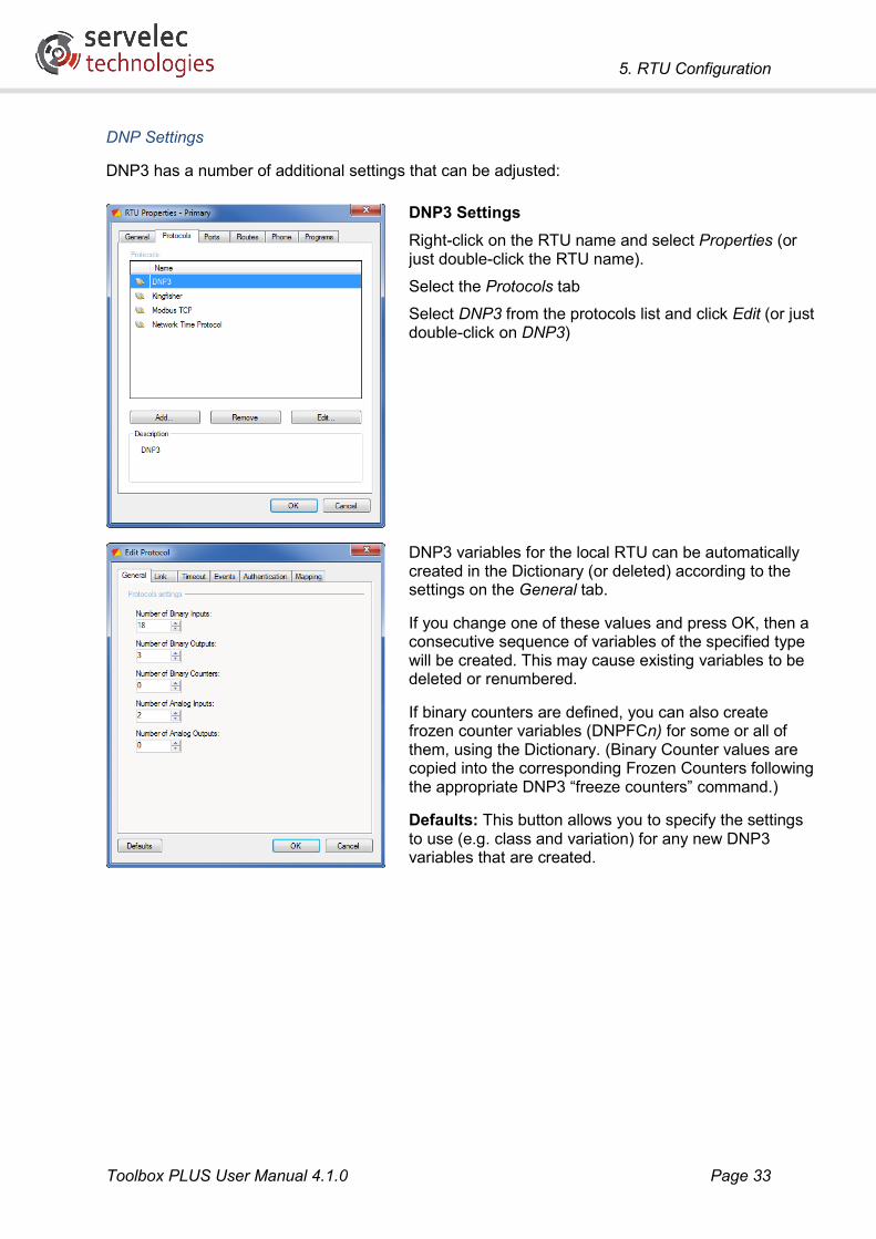
DNP3 Settings
Right-click on the RTU name and select Properties (or just double-click the RTU name).
Select the Protocols tab
Select DNP3 from the protocols list and click Edit (or just double-click on DNP3)
DNP3 variables for the local RTU can be automatically created in the Dictionary (or deleted) according to the settings on the General tab.
If you change one of these values and press OK, then a consecutive sequence of variables of the specified type will be created. This may cause existing variables to be deleted or renumbered.
If binary counters are defined, you can also create frozen counter variables (DNPFCn) for some or all of them, using the Dictionary. (Binary Counter values are copied into the corresponding Frozen Counters following the appropriate DNP3 “freeze counters” command.)
Defaults: This button allows you to specify the settings to use (e.g. class and variation) for any new DNP3 variables that are created.
5. RTU Configuration
Toolbox PLUS User Manual 4.1.0 Page 34
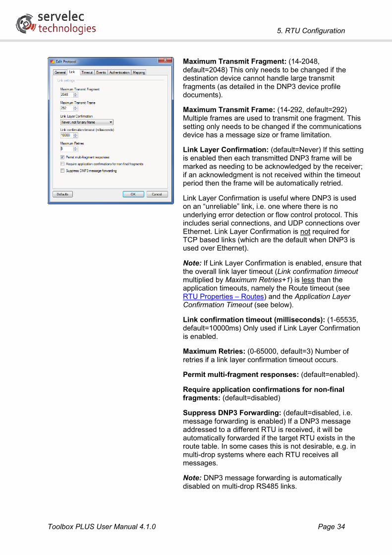
Maximum Transmit Fragment: (14-2048, default=2048) This only needs to be changed if the destination device cannot handle large transmit fragments (as detailed in the DNP3 device profile documents).
Maximum Transmit Frame: (14-292, default=292) Multiple frames are used to transmit one fragment. This setting only needs to be changed if the communications device has a message size or frame limitation.
Link Layer Confirmation: (default=Never) If this setting is enabled then each transmitted DNP3 frame will be marked as needing to be acknowledged by the receiver; if an acknowledgment is not received within the timeout period then the frame will be automatically retried.
Link Layer Confirmation is useful where DNP3 is used on an “unreliable” link, i.e. one where there is no underlying error detection or flow control protocol. This includes serial connections, and UDP connections over Ethernet. Link Layer Confirmation is not required for TCP based links (which are the default when DNP3 is used over Ethernet).
Note: If Link Layer Confirmation is enabled, ensure that the overall link layer timeout (Link confirmation timeout multiplied by Maximum Retries+1) is less than the application timeouts, namely the Route timeout (see RTU Properties – Routes) and the Application Layer Confirmation Timeout (see below).
Link confirmation timeout (milliseconds): (1-65535, default=10000ms) Only used if Link Layer Confirmation is enabled.
Maximum Retries: (0-65000, default=3) Number of retries if a link layer confirmation timeout occurs.
Permit multi-fragment responses: (default=enabled).
Require application confirmations for non-final fragments: (default=disabled)
Suppress DNP3 Forwarding: (default=disabled, i.e. message forwarding is enabled) If a DNP3 message addressed to a different RTU is received, it will be automatically forwarded if the target RTU exists in the route table. In some cases this is not desirable, e.g. in multi-drop systems where each RTU receives all messages.
Note: DNP3 message forwarding is automatically disabled on multi-drop RS485 links.

5. RTU Configuration
Toolbox PLUS User Manual 4.1.0 Page 35
The following settings apply when the RTU is operating as a DNP3 slave.
Timer Poll (milliseconds): (1-65535) Specifies how often to check the static value of every DNP3 variable for change. Events are created for any variable that has changed and has a class assignment of 1, 2 or 3.
Application layer confirmation timeout (milliseconds): (1-65535, default=10000ms) Specifies how long to wait for a confirmation that event data has been received by the master.
Note: If Link Layer Confirmation is enabled, this parameter should be set to a value greater than the overall link layer timeout (Link Layer Confirmation Timeout multiplied by Max Retries+1)
Select timeout (milliseconds): (1-65535, default=10000) Specifies how long to wait for an Operate command after receiving a Select command.
The following settings apply when the RTU is operating as a DNP3 slave.
DNP3 Master Addresses: (0-65535) A comma separated list of DNP3 master addresses (see below).
Limit event reporting to only DNP3 master addresses specified: (default=disabled) If enabled, events will only be reported to the specified list of DNP3 masters. Status responses and static variable values will still be reported to any master.
Enable unsolicited reporting: (default=disabled) When enabled, the RTU will automatically send an unsolicited report if there are new Class 1, 2 or 3 events (when enabled respectively). These will be sent to the specified list of master addresses.
If unsolicited reporting is enabled here, it may still be disabled during operation by a request from the DNP3 master, or by executing the DNPS_UNSOL_DISABLE function block.
If unsolicited reporting is disabled here, unsolicited reports will never be sent.
Event buffer: Not used.
Update static points with event data: (default=disabled) If enabled, the RTU will update its static DNP3 variables based on event data.

5. RTU Configuration
Toolbox PLUS User Manual 4.1.0 Page 36
Require authentication for critical functions: (default=disabled) Used for DNP3 Slave RTUs when security is required. When enabled, an Update key can be entered (consisting of 16 hexadecimal bytes). This Update key must then be provided by a DNP3 master device before it can request a critical function.
For a DNP Master RTU, authentication is configured for each route that is used to communicate with a Secure DNP3 Slave RTU.
Critical functions requiring authentication (according to the DNP3 Secure Authentication standard) are: Write; Select; Operate; Direct Operate; Direct Operate No Acknowledgement; Cold restart; Warm Restart; Initialise Application; Start Application; Stop Application; Enable Unsolicited Messages; Disable Unsolicited Messages; Record Current Time; Authenticate; and Activate Configuration.
Session key timeout: (0-99999 minutes) The Update key is used to create an initial session key. The session key is automatically changed each Session Key Timeout interval to protect against “replay” attacks.
Authentication reply timeout: (2-600 seconds) How long to wait for a reply to the initial authentication message.
Mapping is useful for data concentration. DNP3 objects obtained from remote RTUs can be stored as if they are objects in the local RTU.
To prevent local and remote objects clashing, objects from the remote RTU are given a numeric offset.
For example, if the offset for a given RTU address is set to 1000 then all objects read from that address will be copied to local objects with indexes offset by 1000.
Select the Add button to add a new mapping or select an existing mapping and then select Edit or Remove.
Data Concentration Using Mapping
Data concentration involves an intermediate RTU polling a number of outstation RTUs, and then itself being polled by a DNP3 master. It will then return its own data, plus data read from the outstations.

5. RTU Configuration
Toolbox PLUS User Manual 4.1.0 Page 37
The steps required to achieve this are:
• On the intermediate RTU, configure a mapping (numeric offset) for each outstation.
• Define logic on the intermediate RTU to poll the outstations.
• Define DNP3 points on the intermediate RTU to hold the values read from the outstations. For example, if an outstation has 5 binary input points (DNPBI0-4) and its offset is set to 1000 then you would need to create 5 binary input points DNPBI1000-1004.
If the intermediate RTU is now polled by a DNP3 master, the RTU will return any events and static values previously read from the outstations, in addition to its own local points.
5.4.4 Allen Bradley DF-1
This protocol allows serial communications with an SLC500 PLC using the DF-1 protocol in half duplex slave mode. The data format is 8 data bits, 1 stop bit and no parity. The RTU always operates as the master – messages are generated using custom ISaGRAF function blocks.
Data read using the Allen Bradley protocol are transferred using a block of local Kingfisher registers (KFRnn).
5.4.5 SNMP
Simple Network Management Protocol or SNMP is supported on the processor Ethernet ports. The RTU supports the following modes of operation:
• The RTU can be an SNMP Manager (master), and can send query messages to other devices using custom ISaGRAF function blocks.
• The RTU can be an SNMP Agent (slave), where it responds to incoming queries.
• The RTU can send or receive SNMP Trap messages (asynchronous notifications) using ISaGRAF custom function blocks.
Note that each of the above is treated as a separate protocol, and must be added and enabled separately.
When operating as a slave, the RTU makes available certain configuration and status information. These are defined in the RTU MIB (Management Information Block) document, which is available on the Servelec Technologies website. The SNMP object identifier (OID) codes for Kingfisher RTUs are in the range 1.3.6.1.4.1.27982.1.n.n.n. These data include:
• RTU address and name
• Event log information
• Network interface and traffic information
The SNMP Slave Daemon has the following protocol settings that can be edited. To bring up this dialog, double click on SNMP Daemon (Slave) in the RTU Properties protocol list.

5. RTU Configuration
Toolbox PLUS User Manual 4.1.0 Page 38
Public community name: (default=”public”)
Private community name: (default=”private”)
These are effectively passwords that can be used to restrict access to the information that the RTU makes available via SNMP. Data will be made available if the client specifies either of the configured passwords.
5.4.6 HART
The HART protocol can only be used with a HART option board and is automatically added to the RTU when a HART port is added to the RTU configuration.
The RTU supports the master end of this protocol. Messages can be initiated by the RTU using the HART function block, which is based on Revision 5 of the Hart protocol.
HART data is stored in a block of integer and floating point Kingfisher network variables (KFrRn and KFrFn), where r is user-specified and not necessarily the same as the device’s actual
5.4.7 User Defined
The User Defined ISaGRAF function blocks can be used to send and receive arbitrary serial messages. This allows simple serial protocols to be implemented in the ISaGRAF logic program.
5.4.8 SMS
Use the SEND_SMS ISaGRAF function block to send text messages (up to 160 characters) via a compatible 3G router’s Telnet interface.
See Sending an SMS for more information.
5.4.9 NTP
The Network Time Protocol (NTP) allows the RTU time to be periodically synchronized with a network time server. This is done by having the RTU send request messages to UDP port 123.
NTP can operate using any Ethernet port: either the CP-30/MC-31 main Ethernet port, or a port fitted with a T3/A3 option card. As with other protocols, NTP needs to be enabled on the required port before it can be used.
As with other master protocols, the destination IP address (i.e. the address of the time server) and the Ethernet port to use are specified by defining a route. The route’s “Target RTU” address may be set to any unused address – this number is not used by the protocol itself, but it can be used in logic for updating the route target IP address (using KF_SET_ROUTE) or querying communication statistics (KF_GET_COMM_STATS).
Unlike other master protocols, there is no function block defined for NTP. NTP requests are sent automatically, at the configured rate. (If requested by the server, the RTU may increase the interval between polls to reduce server load.)

5. RTU Configuration
Toolbox PLUS User Manual 4.1.0 Page 39
It is important to note that the time supplied by an NTP server is an absolute time, in UTC. This implies that the RTU’s system time must also operate using UTC. If NTP is used, you should configure a time zone for the RTU (see RTU Time Zone). This allows times to be displayed in local time (or UTC, if you prefer), while internally the RTU’s clock runs on UTC.
The following NTP settings are available:
NTP Settings
Right-click on the RTU name and select Properties (or just double-click the RTU name).
Select the Protocols tab
Select Network Time Protocol from the protocols list and click Edit (or just double-click on Network Time Protocol)
Update Interval (seconds): (60-999999, default=600) How often to check and update the RTU time.
As noted above, the NTP server IP address is specified by creating a route.

5. RTU Configuration
Toolbox PLUS User Manual 4.1.0 Page 40
5.4.10 VRRP
A large telemetry system which uses TCP/IP networking may be set up so that a number of slave RTUs on a LAN all use one master RTU as the gateway to the wider network. That is, on each slave RTU the Ethernet port Gateway IP address is set to that of the master RTU.
If the gateway RTU (or its network interface) fails, all of the slave RTUs will no longer be able to communicate outside the LAN.
The Virtual Router Redundancy Protocol (VRRP) is designed to allow multiple RTUs to act as a set of redundant gateways, which then appear to be a single “virtual router”.
At any one time, one of the RTUs with VRRP enabled will be the active gateway. It will use a configured IP address (which the slave RTUs will be configured to use as their gateway address) and a special hardware (MAC) address (00:00:5E:00:01:xx where xx = the configured “Virtual Router ID”) on its main Ethernet port.
The active gateway RTU will also send out periodic broadcasts (to the multicast address 224.0.0.18), which indicate to the standby gateway RTU(s) that it is still functional. If these broadcasts are no longer detected then a standby gateway RTU will configure its Ethernet port to use the configured gateway IP address and the special MAC address and will therefore seamlessly take over the routing function.
The active/standby VRRP status of a gateway RTU can be checked using the VRRP function block in an ISaGRAF logic program.
To use this feature, two or more gateway RTUs need to have the VRRP protocol enabled, and then configured using the following settings:
Virtual Router ID: (1-255) This is an arbitrary identifier. It must be set to the same value on all gateway RTUs.
Priority: (1-255) This is used if there are multiple standby gateway RTUs, to decide which one will become active.
Interval (seconds): The interval used by the active gateway RTU when sending the periodic VRRP broadcasts.
Virtual IP Address: The IP Address to be shared between the gateway RTUs. All slave RTUs should be configured to use this address as their gateway address.

5. RTU Configuration
Toolbox PLUS User Manual 4.1.0 Page 41
5.4.11 Terminal Server
Overview
The Terminal Server protocol is used to transparently route data between an Ethernet port and a serial port. This means that software which normally uses a serial port to talk directly to a device can, with the help of a serial to Ethernet converter, communicate with the device remotely via an IP network.
For example, consider a device with an RS232 interface which may be configured by connecting a serial cable from a local PC workstation to the device and then running configuration software on the workstation, as shown below.
This function may be performed remotely by enabling the Terminal Server protocol on the RTU. The following diagram shows a typical configuration.
Workstation
Device configuration software
Serial port
serial
Device
Serial port
RS232/485
RTU
Workstation
Device configuration software
Virtual COM port software
Ethernet port (Terminal server protocol)
Serial port (Terminal server protocol)
Device
Ethernet port
IP network
Serial port
serial
RS232/485
Pass-through route

5. RTU Configuration
Toolbox PLUS User Manual 4.1.0 Page 42
In this case, virtual COM port software (e.g. TCP-COM, by PC Micro) is run on the workstation. Any commands sent by the device configuration software to the virtual COM port are forwarded to the RTU’s IP address via the IP Ethernet network.
Alternatively, an external serial-to-Ethernet converter (e.g. Moxa NPort 5110) may be used instead of the virtual COM port software.
The RTU performs a similar function when configured for the Terminal Server protocol –commands received via the Ethernet port are forwarded to an RTU serial port and thence to the device. Responses from the device are returned to the configuration software in a similar way.
Note that while the terminal server protocol supports bidirectional data transfer, all connections must be initiated by the workstation. It is therefore most suitable for poll-response protocols where the workstation sends a command to the device and the device responds. If unsolicited serial data is sent by the device then it will be discarded, until a connection is made from the workstation to the RTU. Once a connection has been established, any subsequent data sent by the device will be forwarded to the workstation.
Configuring the Workstation
The first step is to configure workstation software:
• Ensure that the serial configuration (COM port number, baud rate etc.) specified for the device configuration software matches the settings for the virtual COM port software or external serial-to-Ethernet converter.
• Configure the virtual COM port software or external serial-to-Ethernet converter to connect to the RTU’s IP address. By default, port 4000/TCP is used, although this can be changed, as described below.
Configuring the RTU
Now the RTU can be configured. The first step is to enable the Terminal Server protocol, which is done in the same way as any other protocol:
• Add the Terminal Server protocol to the configuration, on the RTU Properties dialog, Protocols tab.
• Add the Terminal Server protocol to one Ethernet and one serial port. These may be local CP-30 ports or MC-31 ports.
The next step is to define a pass-through route between the Ethernet port and the serial port. This is done using the Pass Throughs tab on the RTU Properties dialog.

5. RTU Configuration
Toolbox PLUS User Manual 4.1.0 Page 43
If no pass through routes have been defined then there will be nothing to display on this tab. Press Add to define a new route.
If the Add button is disabled, check that you have enabled the Terminal Server protocol on both an Ethernet port and a serial port.
Serial port: Select the required serial port. Only those ports that have Terminal Server protocol enabled will be listed.
Ethernet port: Select the required Ethernet port.
Port number: (1-65535) The Ethernet port will listen for connections on this TCP/UDP port number.
Buffer time: (0-60000) The serial port will buffer received characters for this amount of time (in ms) before sending a packet to the Ethernet port. This can improve efficiency on the IP network. See Time Interval Control.
Type: (TCP or UDP) This specifies the type of IP connection to listen for. Note that UDP does not guarantee delivery of data so if this setting is used then the serial protocol being transported over the link must include its own error detection and retry mechanisms.

5. RTU Configuration
Toolbox PLUS User Manual 4.1.0 Page 44
Once the pass through route has been added, the details will be listed on the Pass throughs tab.
Further pass through routes can now be defined, if desired. Each route needs to use a separate serial port, but they can share the one Ethernet port.
Note: If an Ethernet port is shared by more than one pass through route then each route must have a distinct TCP/UDP port number. For a given Ethernet port, the default port number is 4000 for the first route defined, 4001 for the second, and so on.
To remove a pass through route, simply click on it and then click Remove.

5. RTU Configuration
Toolbox PLUS User Manual 4.1.0 Page 45
5.5 Ports The Ports tab on the RTU Properties dialog is used to configure the physical communications ports in the RTU. These include Ethernet and serial ports, and include ports on the CP-30 processor module and on MC-31 communications modules.
A Kingfisher PLUS RTU can address up to 192 ports (although performance is not guaranteed and users need to consider bandwidth limitations and practise common sense with high port counts). A single CP-30 or MC-31 module supports one fixed Ethernet port, plus up to two additional Ethernet ports or up to four additional serial ports.
CP-30 and MC-31 Module
Port 1 – Ethernet
Option Board Slot 2 (Serial or Ethernet)
Option Board Slot 3 (Serial or Ethernet)
The Ports tab will initially show a list of all fixed ports, i.e. the Ethernet port (Port 1) on the CP-30 and each defined MC-31 module. If option card ports are present, you can add these by clicking the Add button.
Add a Port
Select the Add button to add an option card port.
If you want to change the type or location of an existing option card port, click Remove, then re-add it.

5. RTU Configuration
Toolbox PLUS User Manual 4.1.0 Page 46
Select Port Type
Define the type and location of the option card.
Module: Select the CP-30 or MC-31 module containing the option card.
Type: Select the type of option card. The various different types of port are described below.
Number: Specify the option card slot number within the CP-30 or MC-31 module: 2 (upper slot) or 3 (lower slot)
Once the required ports have been added, most will require various settings to be configured. These are described in the following sections.
5.5.1 Ethernet
A twisted pair 10/100BaseT Ethernet port is included as Port 1 on the CP-30 and MC-31. Additional Ethernet ports may be added to the RTU by installing T3 (twisted pair) or A3 (fibre optic) option cards in Ports 2 or 3 of a CP-30 or MC-31.
To configure Ethernet, double click on the required Ethernet port in the port list on the Ports tab on the RTU Properties dialog (or click Edit). The following settings are available:
IP Address: (default=192.168.0.1) Each Ethernet port must be assigned a valid IP (internet protocol) address which is suitable for the network to which it is connected (check with your network administrator). The assigned IP address must be unique on the local network. In most cases the RTU will be connected to a private LAN, in which case the IP address will be allocated from one of the private address ranges: 10.x.x.x, 172.16-31.x.x or 192.168.x.x
Note: If there are multiple Ethernet ports on a CP-30 or MC-31 module, then each port must be set to a different subnet, which usually means they must be connected to physically separate networks. For example, if Port 1 uses the default IP address and subnet mask (192.168.0.1/255.255.255.0) then Port 2 or 3’s IP address cannot be set to 192.168.0.x (192.168.1.x would be OK).

5. RTU Configuration
Toolbox PLUS User Manual 4.1.0 Page 47
It is also possible to connect a PC directly to an RTU Ethernet port, using a cross-over cable. In this case, the RTU can be set to any address, provided that the PC’s IP address is set to a different address on the same subnet (e.g. if the RTU Ethernet port is left on the default setting of 192.168.0.1 then the PC could to be set to, say, 192.168.0.2).
Subnet Mask: (Default=255.255.255.0) This should be set to the correct subnet mask for the network to which the RTU is connected (check with your network administrator). The subnet mask defines which part of the IP address is used to identify the network (or “subnet”) and which part is used to identify a particular device on the network. With the default setting, the first three numbers in the IP address specify the subnet and the last one specifies one of 256 devices connected to that subnet.
Gateway: (Default=0.0.0.0, i.e no gateway) This specifies the IP address of a device on the local subnet which is able to forward messages to other networks, or the Internet. If not set then the RTU will only be able to communicate with devices that are connected to the local subnet.
If required, each Ethernet port can be assigned its own separate gateway. For example, multiple gateways would be required in applications where the RTU had, for redundancy purposes, two diverse methods for connecting to the outside world. For example, the primary link could be an ADSL modem connected to Port 1 on the CP-30, which would be configured with the ADSL modem’s IP address as the gateway address. The backup link might be a 3G modem connected to Port 1 of the MC-31, which would be configured with its gateway set to the 3G modem’s IP address.
Ethernet ports on different modules (as in the above example) can have independent gateways configured. It is also possible for Ethernet ports in the same module (e.g. ports 1 and 2 of a CP-30) to have independent gateways. See also IP Routes.
Protocols: Protocols which have already been added to the RTU are assigned to the Ethernet port by ticking the appropriate box(es). Note that MC-31 Ethernet ports only support Kingfisher, DNP3, Modbus/TCP, SMS, NTP and Terminal Server protocols. CP-30 Ethernet ports support any Ethernet based protocols.
5.5.2 Serial (RS232/422/485)
Serial ports may be added to the RTU by installing Option I (isolated serial) or Option I2 (dual isolated serial) cards in a CP-30 or MC-31 module. The following electrical standards are supported:
• RS232 uses single-ended signalling and provides point-to-point communication over relatively short distances (typically up to 15m, depending on baud rate). The link is full-duplex (separate wires for each data direction). RTS and CTS signals are available on the connector and can be used for flow control.
• RS422 uses differential signalling to provide point-to-point or multi-drop communication over longer distances (typically up to 1000m, depending on baud rate). The link is full-duplex (separate pairs for each data direction). The RTS signal is used to enable the transmitter.

5. RTU Configuration
Toolbox PLUS User Manual 4.1.0 Page 48
• RS485 also uses differential signalling, but is half-duplex. A single pair of wires is used to connect multiple devices in a multi-drop configuration. Protocols used over RS485 must ensure that only one device transmits at a time. The RTS signal is used to enable the transmitter.
To change the serial port settings, double click on the port in the port list on the Ports tab.
Type: (default=RS232) Specifies the electrical standard (RS232/422/485).
Bits per second: The speed at which the RTU will send or receive messages (75-115200bps).
Data Bits: Number of data bits transmitted per byte. Must be 8 for any protocol that transmits 8-bit data.
Parity: Specifies whether even, odd or no parity is used.
Stop Bits: Specifies whether 1 or 2 stop bits are used.
Ensure that the above settings match those of the device with which you are communicating. Note also that for Modbus/ASCII protocol, these settings will be ignored and the following fixed settings used: 7 data bits, Even parity, 1 stop bit.
Protocols: A protocol already added to the RTU can be enabled on the port. Only one protocol can be enabled for serial ports.
Pre-Transmission delay (milliseconds): (default=0) Specifies how long the RTS signal is asserted for before data is sent. Typically set to zero for RS232 or 10 ms for RS485 and RS422.
Post-Transmission delay (milliseconds): (default=0) Specifies how long RTS is asserted for after the data has been sent
Quiet time (milliseconds): (default=0) The RTU will wait until the line has been quiet (no received messages) for the specified time before sending a message.
Enable external modem support: (default=disabled) When enabled, allows an external PSTN modem to be connected to the serial port. Modem settings can then be configured as for a Dialup port as detailed below.
5. RTU Configuration
Toolbox PLUS User Manual 4.1.0 Page 49
5.5.3 Serial (Fibre Optic)
The Option F card is the same as the serial (Option I) card, except that a fibre optic physical interface is used. This allows transmission over distances up to 4km.
5.5.4 Dual Serial
The Option I2 card supports two independent isolated serial ports, each of which is identical to that on the Option I card.
The ports are identified using a two part notation: slot.port, where slot is the option card slot number (2 or 3) and port is the port number within the card (1 or 2). Thus if two Option I2 cards are installed in a module, the four serial ports would be numbered as follows, from top to bottom: 2.1, 2.2, 3.1, 3.2.
This notation can be used with ISaGRAF function blocks that take a port number as a parameter, such as KF_GET_PORT_STATS. For example, if an MC-31 in slot 15 has an Option I2 card installed in the lower option card slot then you would specify its ports as ‘15:3.1’ and ’15:3.2’.
When an Option I2 card is added, two serial ports are automatically added to the port list (e.g. port 2.1 and port 2.2). These can then be configured independently. Note however that if either port is subsequently deleted, both ports will be removed.
5.5.5 Dialup
The Dialup option board (Option D) incorporates a 33.6 kbps PSTN modem.
The basic serial port settings on the Settings tab are the same as for the Serial option cards – you need to specify the baud rate and other serial parameters, and select the protocol (only one) that is assigned to the port.
For a PSTN modem, the settings on the Transmission tab are not relevant and should normally all be left on zero.
The Modem tab contains settings relating to the modem. These are also used when connecting to an external modem using a serial option card.

5. RTU Configuration
Toolbox PLUS User Manual 4.1.0 Page 50
Initialisation string: (default: AT&FTE0V0S0=2&W) These characters are sent to the modem to initialise it after start-up, after disconnection, and if a dial attempt fails. The default string will load factory default settings (&F), select tone dialling (T), switch off command echo (E0), select numeric response codes (V0), enable auto-answer (S0=2) and then save the settings (&W)
Note: X3 (disable dial tone detection) can be added to the default string if the modem is unable to recognize the dial tone or is experiencing problems establishing a connection i.e. AT&FTE0V0S0=2X3&W
Dial timeout (seconds): (0-10000) The time to wait from the time when dialling begins until a Carrier Detect indication is received. When dialling a GSM modem, the Dial Timeout should be set to at least 45 seconds.
Inactivity timeout (seconds): (0-10000) The RTU will hang up after this amount of time has elapsed since the last message was received. A value of 0 disables the function.
Hang-up timeout (seconds): (0-10000) The RTU will hang up after this amount of time has elapsed after connection or after sending the last message. A value of 0 disables this function.
Remaining Online
To remain online after connection, set Inactivity timeout to 0 and Hang-up timeout to 0 in both RTUs in the dialup link. If the line is disconnected, the RTU will reconnect when the next TX or RX message is initiated from ladder logic.
Dialling a Paging Service
If experiencing problems, error correction may need to be disabled by including '\N0' i.e. AT&FE0V0S0=2\N0&W. If experiencing problems when using an MC module and a Dial option board, the baud rate may need to be limited to 9600 by including F8 in the initialisation string i.e. AT&FE0V0S0=2F8&W.
5.5.6 Line
The Line option card (Option L) is used to connect to a private line or analog radio. The board is optically isolated, operates at 1200 bps and provides FSK CCITT V.23 modulation.
The basic serial parameters (Settings tab) are fixed at 1200 baud for the Line option card. The desired protocol will still need to be selected.
The transmit timing parameters (Transmission tab) may need to be adjusted when using the Line option card:
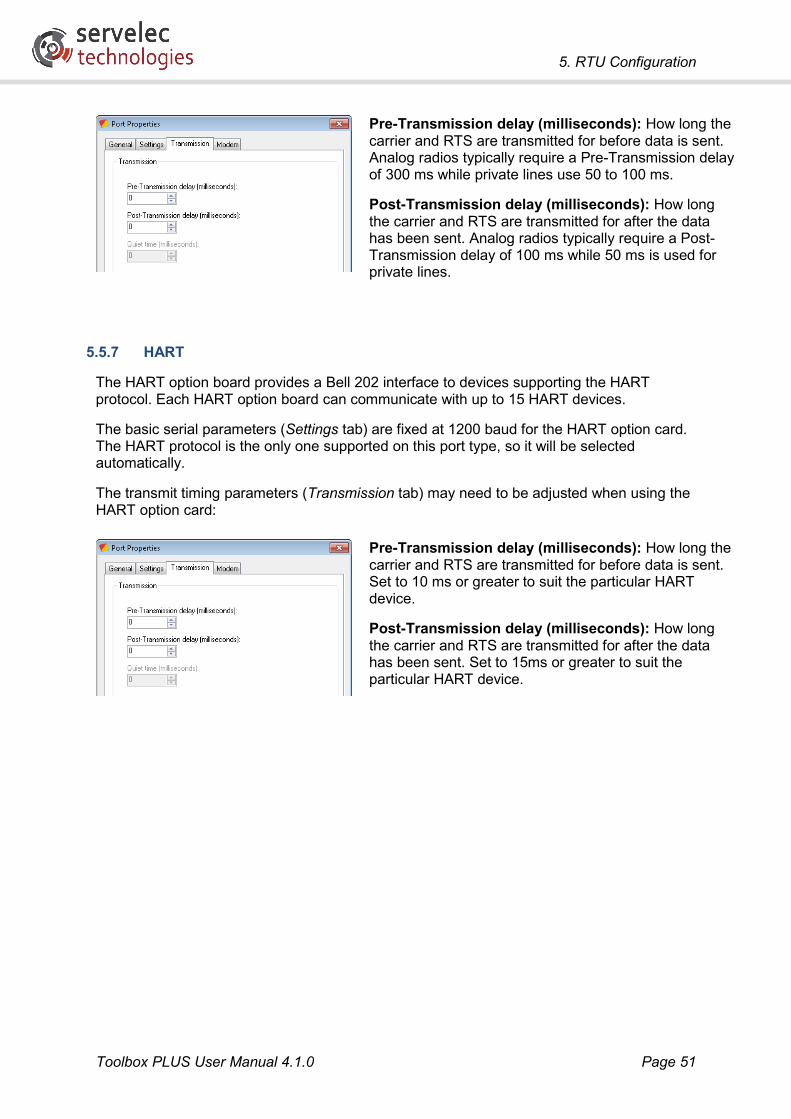
5. RTU Configuration
Toolbox PLUS User Manual 4.1.0 Page 51
Pre-Transmission delay (milliseconds): How long the carrier and RTS are transmitted for before data is sent. Analog radios typically require a Pre-Transmission delay of 300 ms while private lines use 50 to 100 ms.
Post-Transmission delay (milliseconds): How long the carrier and RTS are transmitted for after the data has been sent. Analog radios typically require a Post-Transmission delay of 100 ms while 50 ms is used for private lines.
5.5.7 HART
The HART option board provides a Bell 202 interface to devices supporting the HART protocol. Each HART option board can communicate with up to 15 HART devices.
The basic serial parameters (Settings tab) are fixed at 1200 baud for the HART option card. The HART protocol is the only one supported on this port type, so it will be selected automatically.
The transmit timing parameters (Transmission tab) may need to be adjusted when using the HART option card:
Pre-Transmission delay (milliseconds): How long the carrier and RTS are transmitted for before data is sent. Set to 10 ms or greater to suit the particular HART device.
Post-Transmission delay (milliseconds): How long the carrier and RTS are transmitted for after the data has been sent. Set to 15ms or greater to suit the particular HART device.

5. RTU Configuration
Toolbox PLUS User Manual 4.1.0 Page 52
5.5.8 Spread Spectrum Radio
There are three types of Spread Spectrum radio option boards available for the CP-30 and MC-31 modules:
Country Option Board Carrier Frequency Baud USA R4 900 MHz 9600 International R3 2400 MHz 19200 Australia R2 900 MHz 9600
The basic serial parameters (Settings tab) are fixed at the baud rate indicated above. The desired protocol will still need to be selected.
The parameters on the Transmission tab are not applicable for the SSR option card.
The settings on the Radio tab are as follows:
Point to point mode: Selects Point to Point or Point to Multipoint operation.
Vendor ID: (16-32767, default=13106) Sets the ID number of the Spread Spectrum radio. All radios on the same network need to have the same Vendor ID in order to communicate with each other. It is recommended that Vendor ID be changed to avoid interference with other radio networks.
Destination address: (0-65535, default=65535) Sets the Destination address of the Spread Spectrum radio. All radios on the same network need to have the same Destination Address in order to communicate with each other. It is recommended that Destination Address be changed to avoid interference with other radio networks.
Hopping pattern: (0-6, default=0) Sets the Hopping pattern of the Spread Spectrum radio. All radios on the same network need to have the same Hopping pattern to enable them to communicate. To minimize interference from another RTU using a spread spectrum radio, a hopping pattern number that is different to the offending radio should be used.
In standard configurations the Vendor ID, Hopping Pattern and Destination Address fields do not need to be modified as the addressing is performed transparently via the RTU addressing system.
It is good practice when implementing a system in a build-up area to not use the default radio settings even if the system is expected to function well. This will help to eliminate interference with other radio devices in the area.

5. RTU Configuration
Toolbox PLUS User Manual 4.1.0 Page 53
5.6 Routes
5.6.1 RTU Networking
An RTU network consists of two or more RTUs that can communicate with each other in some way. The communication path is called a route.
This example shows RTU1 as the master RTU and RTUs 2-4 as the remote RTUs. RTU3 also stores and then forwards messages between RTU1 and RTU4.
Each RTU has a “route table” that is referred to when communicating with other RTUs or devices in the network. Routes only need to be configured for RTUs that are initiating messages. If an unsolicited message is received from a new RTU, the new RTU route information will be automatically added to the working route table configuration.
In the above scenario, RTU1 is set up to poll the three slave RTUs. It therefore needs to have routes defined which tell it how to access each of the slaves.
In particular, it needs to know:
• The address of the target RTU, which will be used as the “destination” field inside the Kingfisher, Modbus or DNP3 messages
• Whether it can send messages directly to the target RTU (a “direct route”), or whether they need to be forwarded by an intermediary (an “indirect route”). In the above example, all messages for RTU4 need to be sent to RTU3, which will then forward them on, so this would be set up as an indirect route.
• The physical port to use to send the message, which may be Ethernet or serial, and may be on the CP-30 or on an MC-31 communications module
• The physical address to send the message to. For a point-to-point serial connection, this is implicit as the cable can only be connected to one other RTU. For a multi-drop serial connection (e.g. RS485), the physical address is generally the same as the RTU address. For Ethernet, the physical address is the IP address.
RTU3 will also need a route set to tell it how to reach RTU4.

5. RTU Configuration
Toolbox PLUS User Manual 4.1.0 Page 54
To configure routes, select the Routes tab on the RTU Properties dialog.
This shows a summary of all defined routes.
To add a new route, click Add; to edit an existing route double click the route, or select it and click Edit.
On the General tab:
Target RTU: (0-65520) The address of the destination RTU to communicate with. Address 0 is only valid for the DNP3 protocol.
Modbus ID: When sending a message using the Modbus protocol, only the lower 8 bits of the destination RTU address will be used. This field indicates the equivalent 8-bit Modbus address for the given target address.
System ID: (00 to FF Hex, default=AE) This is the communications sync character used at the start of outgoing Kingfisher messages. An RTU will only respond to Kingfisher messages that begin with the same System ID as the RTU's own System ID (as configured in the RTU Properties General tab). It is recommended that AE be used for all Kingfisher RTUs except when relaying radio messages as detailed in the topic below Routes - Relaying Radio Messages. System ID is not used by other protocols.
Route: (Direct or Indirect) Direct means the RTU is directly connected to the target RTU (e.g. via a private line or radio link). Indirect means the RTU must communicate via one or more other intermediate RTUs to access the target RTU. When an RTU receives a message that is not for itself, it will forward the message to the target RTU if it has a route configured for that target RTU.
Port / Via RTU: For a Direct connection, this is the local port number to be used to communicate with the target RTU. For an Indirect connection, this is the directly

5. RTU Configuration
Toolbox PLUS User Manual 4.1.0 Page 55
connected RTU address to which the message must be sent in order to reach the target RTU.
IP Address: If the target RTU is connected via Ethernet, its IP address should be set here.
Protocols: This specifies the protocol(s) that will use this route. Protocols must first be added to the RTU configuration and then enabled on the port before they can be used on a route (please see the topic RTU Properties - Protocols).
On the Advanced tab:
Timeout: (0-1000000ms, default 5000ms) The time that an RTU will wait for a reply to its first message. If Retries (see below) is set to 1 or greater and a reply is not received, the RTU will send the message again after the timeout has expired.
Note: As discussed in the DNP3 Settings section, if link layer confirmations are enabled, then the overall link layer timeout (Link confirmation timeout multiplied by Maximum Retries+1) should be set to a value which is less than the Route timeout.
Retries: (0-999) The number of times the RTU will retry sending a message to the target RTU if the previous attempts have failed. The maximum number of attempts is one more than the Retries setting. E.g. if Retries is 3, the RTU will have up to 4 attempts at sending a message.
Retries are generally only useful when using a serial or UDP-based protocol. TCP already includes a retry mechanism so in this case Retries should be set to 0.
In applications where the RTU is regularly polling a slave device, retries should normally only be used if the polling rate is relatively low. For fast poll rates there is no point retrying a poll if the next poll is going to occur within a few seconds anyway.
For DNP3, if retries are required (e.g. because a serial/UDP link is used) then DNP3 Link Layer Confirmations should be enabled. In fact, if the route uses DNP3 then the route Retries setting will be disabled and forced to 0.
Note: when dialling an RTU, the RTU will dial the primary phone number up to Retries+1 times and then will dial the Secondary phone number up to Retries+1 times until the PSTN modem successfully connects or all the dial retries have failed.
5. RTU Configuration
Toolbox PLUS User Manual 4.1.0 Page 56
If the route uses DNP3, the following settings are available:
Permit UDP communications: By default, DNP3 uses the TCP protocol, which provides error checking and flow control. If this option is enabled then UDP will be used instead. UDP is a connectionless protocol, and is somewhat similar to using a serial link.
Note: This setting will be ignored if the route is assigned to an MC-31 Ethernet port. For MC-31 ports, only TCP is supported for outgoing connections.
Enable DNP3 Secure Authentication: Use this option when the local RTU is a DNP3 Master and is communicating with a DNP3 Slave which requires authentication. When enabled, an Update key can be entered.
Session key timeout: The Update key is used to create an initial session key. The session key is automatically changed each Session Key Timeout interval to protect against “replay” attacks.
Authentication reply timeout: How long to wait for a reply to the initial authentication message.
The following sections discuss the route setup for some typical applications.

5. RTU Configuration
Toolbox PLUS User Manual 4.1.0 Page 57
5.6.2 Indirect Routing
In this example, RTU 1 has serial connections to RTU 2 and RTU 3. RTU 3 has a serial connection to RTU 4.
The route configuration described below would allow the master to poll any slave, and any slave to initiate a communication to the master.
RTU Route Target Route RTU 1 RTU 2 Direct via Port 2
RTU 3 Direct via Port 3 RTU 4 Indirect via RTU 3
RTU 2 RTU 1 Direct via Port 2 RTU 3 RTU 1 Direct via Port 2
RTU 4 Direct via Port 3 RTU 4 RTU 3 Direct via Port 2
RTU 1 Indirect via RTU 3
If the system is purely master/slave, i.e. RTU 2-4 do not need to initiate communications to the master, then the route configuration could be simplified. RTU1 would still need three routes so it can reach RTU 2, 3 and 4. However the only other route required would be the direct route from RTU 3 to RTU 4.

5. RTU Configuration
Toolbox PLUS User Manual 4.1.0 Page 58
5.6.3 Relaying Radio Messages
For the radio system below, RTU1 communicates with RTU3 by sending a message to RTU2. RTU2 then forwards the message to RTU3. Due to the radio setup, it is sometimes possible for RTU3 to receive the indirect message that is sent to RTU2. This can cause errors since RTU3 will respond to the message at the same time RTU2 is attempting to forward the message.
To prevent both RTU2 and RTU3 responding at the same time, RTU2 and RTU3 are configured with unique system IDs as shown below. RTU1 sends the indirect message to RTU2 with a System ID of A1. RTU3 will only respond to messages with a system ID of A2 and so ignores the message. When RTU2 forwards the message to RTU3, the message is sent with a System ID of A2. RTU3 then responds to the message.
Note: System IDs 00, AC, A5 and FF are reserved and should not be used.
RTU Route Target Route Sys ID Route RTU 1 RTU 2 A1 Direct via Port 2
RTU 3 A2 Indirect via RTU 2 RTU 2 RTU 1 AE Direct via Port 2
RTU 3 A2 Direct via Port 2 RTU 3 RTU 2 A1 Direct via Port 2
RTU 1 AE Indirect via RTU 2
5.6.4 Dynamic Route Changes
The preceding sections discussed the static configuration of routes in Toolbox PLUS. Routes can also be added and changed dynamically during operation. There are two main cases:
• When the RTU is operating as a slave, an incoming poll from a master will automatically add or update the route to that master. This is done by recording the port and/or IP address from which the request came.

5. RTU Configuration
Toolbox PLUS User Manual 4.1.0 Page 59
• The KF_SET_ROUTE function block can be used to explicitly change an existing route – for example to make it use an alternative port. This is often used in a system with redundant communications links, to switch traffic to an alternative link when a communications failure is detected. Note that an existing route to the destination RTU must already exist; this function block cannot be used to create a new route.
The general rule is that a route should be statically configured in Toolbox PLUS if the RTU needs to initiate messages to a remote RTU (e.g. it is configured as a master, or it needs to forward messages to another RTU, or it needs to be able to send unsolicited DNP3 messages before any poll messages have been received). If the RTU is acting purely as a slave device then entering a static route to the master is not necessary.
Dynamic route updates do not actually change the RTU configuration. This means that if the RTU restarts then it will revert to its statically configured routes. Also, if you upload the configuration to Toolbox PLUS during operation, any dynamic routes will not be visible.
Be aware that a route set dynamically using one of the above two methods may be subsequently overridden by the other method being triggered, which can sometimes cause surprising results.
For example, suppose logic similar to that described in Redundant Communications is used to switch routes when a communications failure is detected. Then if the cable is removed, the route will switch to the alternative port. If the cable is then restored within a minute or two, buffered messages in the remote device may be retransmitted and received by the RTU, which will cause the route to be updated (i.e. restored to the original port).
5.6.5 IP Routes
When sending a poll or response message via an Ethernet port, IP (Internet Protocol) routing rules are used by the CP-30 or MC-31 module to determine which of its Ethernet ports to use, if it has more than one.
This decision is based on the destination IP address to which the message is being sent. Normally, the rule is simple: if the destination is on the same subnet as one of the module’s Ethernet ports, then that port is used. Otherwise, if a gateway address is defined for one port, then that port is used.
Note that IP routing rules may override route settings configured in the RTU route table. For example, suppose Port 1 and Port 2 on a CP-30 have IP addresses 192.168.0.1 and 10.0.0.5 respectively. If you were to define an RTU route that specifies Port=1, Address=10.0.0.7 then the “Port=1” setting would be ignored. Port 2 would be used because the destination address’s subnet matches that of Port 2.
What if more than one of a module’s ports has a gateway address defined? The following rules apply:
• When operating as a slave, a CP-30 or MC-31 module will always transmit the response to a poll via the Ethernet port on which the poll message was received.
• If an RTU route which uses a CP-30 port is set or updated then an IP route is automatically set, to ensure that the configured CP-30 port is used for sending outgoing request messages.

5. RTU Configuration
Toolbox PLUS User Manual 4.1.0 Page 60
5.7 Phone Numbers If an RTU uses a PSTN port to communicate with remote RTU(s) then the phone number of each remote RTU is configured on the Phone tab on the RTU Properties dialog.
Add, Remove or Edit Phone Number
Select the Add button to add a phone number, or select an existing phone number in the list and then select the Edit or Remove button
Target RTU: (1-65520) The address of the destination RTU to dial.
Primary phone number: The initial phone number to dial. If connection fails, the RTU will dial the Primary phone number again, up to number of retries configured for the port. Spaces used in the phone number will be ignored by the modem.
Secondary phone number: The backup phone number to dial if the Primary phone number fails.

5. RTU Configuration
Toolbox PLUS User Manual 4.1.0 Page 61
5.8 Programs One or more programs can be added to the RTU to provide logic processing capability. When editing a program, Toolbox PLUS launches the ISaGRAF Workbench editor. Programs or function blocks can also be imported from other RTU configurations or projects.
Programs can be added in the following IEC61131 languages:
Functional Block Diagram (FBD) is a graphic language. It allows the programmer to build complex procedures by taking existing functions from the standard library or from the function or function block section.
Ladder Diagram (LD) is a graphic representation of Boolean equations, combining Contacts (input arguments) with Coils (output results). The LD language enables the description of tests and modifications of Boolean data by placing graphic symbols into the program chart. LD graphic symbols are organized within the chart exactly as an electric Contact diagram. LD diagrams are connected on the left side and on the right side to vertical Power Rails. Please see the topic ISaGRAF – Logic Examples for Ladder Diagram examples.
Sequential Function Chart (SFC) is a graphic language used to describe sequential operations. The process is represented as a set of well-defined Steps, linked by Transitions. A Boolean Condition is attached to each Transition. A set of Actions are attached to each Step. For programs, Conditions and Actions are detailed using three other languages: ST, IL, or LD. For function blocks, Conditions and Actions are detailed using only two other languages: ST or LD. From Conditions and Actions, any Function or Function Block in any language can be called.
Structured Text (ST) is a high level structured language designed for automation processes. This language is mainly used to implement complex procedures that cannot be easily expressed with graphic languages. ST language can be used for the description of the actions within the Steps and conditions attached to the Transitions of the SFC or the Actions and Tests of the FC language.
Flow Chart (FC) is a graphic language used to describe sequential operations. A Flow Chart diagram is composed of actions and tests. Between actions and test are oriented links representing data flow. Actions and tests can be described with ST, LD or IL programs. Functions and Function blocks of any language (except SFC) can be called from actions and tests. A Flow Chart program can call another Flow Chart program. The called FC program is a sub-program of the calling FC program.
Instruction List (IL) is a low level language. Instructions always relate to the current result (or IL register). The operator indicates the operation that must be made between the current value and the operand. The result of the operation is stored again in the current result.
The Programs tab lists all currently defined logic programs:
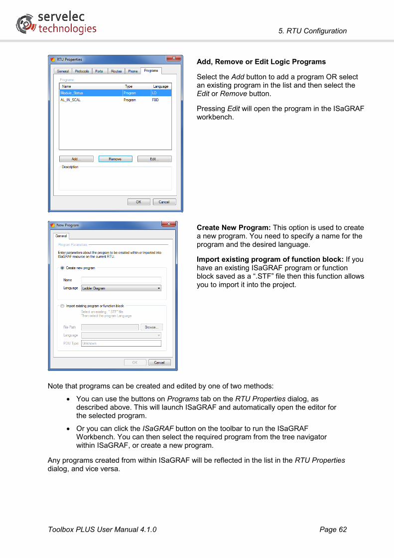
5. RTU Configuration
Toolbox PLUS User Manual 4.1.0 Page 62
Add, Remove or Edit Logic Programs
Select the Add button to add a program OR select an existing program in the list and then select the Edit or Remove button.
Pressing Edit will open the program in the ISaGRAF workbench.
Create New Program: This option is used to create a new program. You need to specify a name for the program and the desired language.
Import existing program of function block: If you have an existing ISaGRAF program or function block saved as a “.STF” file then this function allows you to import it into the project.
Note that programs can be created and edited by one of two methods:
• You can use the buttons on Programs tab on the RTU Properties dialog, as described above. This will launch ISaGRAF and automatically open the editor for the selected program.
• Or you can click the ISaGRAF button on the toolbar to run the ISaGRAF Workbench. You can then select the required program from the tree navigator within ISaGRAF, or create a new program.
Any programs created from within ISaGRAF will be reflected in the list in the RTU Properties dialog, and vice versa.
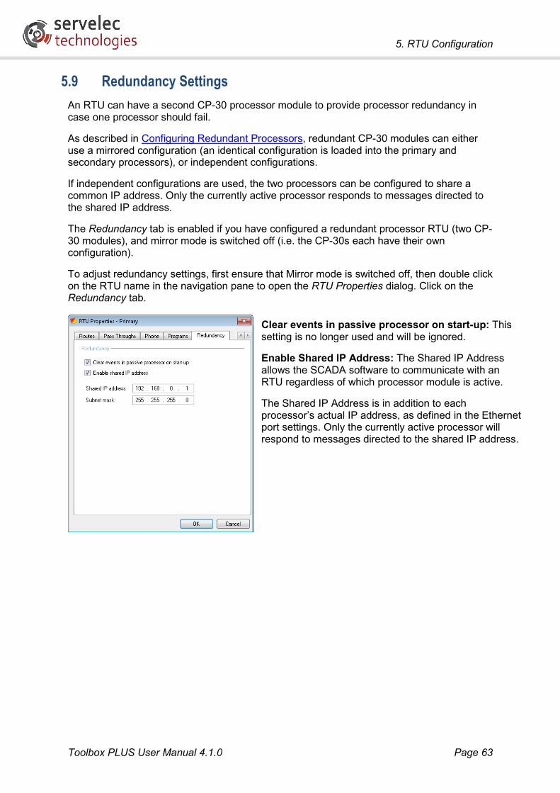
5. RTU Configuration
Toolbox PLUS User Manual 4.1.0 Page 63
5.9 Redundancy Settings An RTU can have a second CP-30 processor module to provide processor redundancy in case one processor should fail.
As described in Configuring Redundant Processors, redundant CP-30 modules can either use a mirrored configuration (an identical configuration is loaded into the primary and secondary processors), or independent configurations.
If independent configurations are used, the two processors can be configured to share a common IP address. Only the currently active processor responds to messages directed to the shared IP address.
The Redundancy tab is enabled if you have configured a redundant processor RTU (two CP-30 modules), and mirror mode is switched off (i.e. the CP-30s each have their own configuration).
To adjust redundancy settings, first ensure that Mirror mode is switched off, then double click on the RTU name in the navigation pane to open the RTU Properties dialog. Click on the Redundancy tab.
Clear events in passive processor on start-up: This setting is no longer used and will be ignored.
Enable Shared IP Address: The Shared IP Address allows the SCADA software to communicate with an RTU regardless of which processor module is active.
The Shared IP Address is in addition to each processor’s actual IP address, as defined in the Ethernet port settings. Only the currently active processor will respond to messages directed to the shared IP address.

5. RTU Configuration
Toolbox PLUS User Manual 4.1.0 Page 64
5.10 Module Properties Modules and cards have properties that can be configured after the module or card has been added to the RTU configuration.
To edit a module’s properties, first ensure that the list of modules is displayed (select the Projects workspace), then double click on the desired module. This will display the Edit Module dialog.
This dialog has a General tab, plus other tabs which vary according to module type. The following sections describe the available settings for each module type.
On the General tab you can change the module’s slot number. If you want to change the type of module then it is necessary to delete the module from the configuration and then add a new one.
For technical information about the various module types, refer to the Kingfisher PLUS+ Hardware Reference Manual, available for download from the Servelec Technologies website.
5.10.1 PS-1x/2x
On the Configuration tab:
Battery: The capacity of the installed backup battery.
5.10.2 CP-30
On the Ports tab:
The CP-30’s communications ports can be added, removed or edited, as described in RTU Properties - Ports.
On the Advanced tab (only visible when the Mirror button is switched OFF):
Trigger Execution Timeout (ms): For firmware version 2981 or later this setting is no longer used and will be ignored.

5. RTU Configuration
Toolbox PLUS User Manual 4.1.0 Page 65
5.10.3 MC-31
On the Ports tab:
The MC-31’s communications ports can be added, removed or edited, as described in RTU Properties - Ports.
5.10.4 AI-1/4
On the Configuration tab:
Scan Rate: How often to scan all the analog input channels
On the Scaling tab:
The minimum and maximum set-points allow an analog input (with a raw range of 0-32760) to be scaled to a defined range. The scaled value will be stored in the analog input variable.
Minimum: The desired variable value when the raw value is 0.
Maximum: The desired variable value when the raw value is maximum (32760).

5. RTU Configuration
Toolbox PLUS User Manual 4.1.0 Page 66
5.10.5 AI-10
On the Configuration tab:
Channel Range: The current or voltage input range for that channel. Each channel can be configured individually.
The available ranges are:
• 4 – 20 mA (default)
• 0 – 20 mA
• +/- 10 mA or +/- 2.5V
• +/- 20 mA or +/- 5V
• +/- 10V
AI-10 version 1.x modules may be ordered as current input (AI-10) or voltage input (AI-10-V). For AI-10 version 2.x modules, selecting between current and voltage can be done using jumper links.
For the 0 – 20 mA or 4 – 20 mA ranges, the input will return zero if the current is negative or below 0 or 4 mA respectively.
On the Scaling tab:
The minimum and maximum set-points allow an analog input (with a raw range of 0-32767) to be scaled to a defined range. The scaled value will be stored in the analog input variable.
Minimum: The desired variable value when the raw value is 0.
Maximum: The desired variable value when the raw value is maximum (32767).
Note: For inputs configured with a bipolar range (i.e. +/- 2.5V, +/- 5V or +/- 10V), the Minimum set-point should normally be set to 0. The scaling is symmetrical about the minimum value, e.g if Minimum=0 and Maximum=100 then a raw value of 32760 will produce a scaled value of 100, and a raw value of -32760 will produce a scaled value of -100.

5. RTU Configuration
Toolbox PLUS User Manual 4.1.0 Page 67
5.10.6 AO-2/3
On the Scaling tab:
Minimum: The variable value that will produce a minimum raw output value (0).
Maximum: The variable value that will produce a maximum raw output value (32760).
5.10.7 IO-3/4/5
On the Configuration tab:
Failsafe Outputs: If enabled and there is no communications activity between the processor and any module on the backplane for 10 seconds the module assumes that the processor has failed and sets the outputs OFF (open). If not enabled (default), all digital outputs will hold their last value.
Note: Failsafe Outputs are not supported on IO-4 modules.
On the Scaling tab:
For analog inputs:
Minimum: The desired variable value when the raw value is 0.
Maximum: The desired variable value when the raw value is maximum (32760).
For analog outputs:
Minimum: The variable value that will produce a minimum raw output value (0).
Maximum: The variable value that will produce a maximum raw output value (32760).

5. RTU Configuration
Toolbox PLUS User Manual 4.1.0 Page 68
5.10.8 DO-1/2/5/6 & IO-2
On the Configuration tab:
Failsafe Outputs: If enabled and there is no communications activity between the processor and any module on the backplane for 10 seconds the module assumes that the processor has failed and sets the outputs OFF (open). If not enabled (default), all digital outputs will hold their last value.
5.10.9 DI-10
On the Configuration tab:
Channel Inversion: (Tick to enable each channel or select Ch Inv button to enable/disable all channels)
By default, when a high voltage level is applied to an input channel, a logical 1 is recorded in the input register and the channel LED is set ON. If the channel inversion option is selected then a high input voltage will result in a logical 0 being recorded in the input register and the channel LED will be set OFF.
Sequence-of-Events: (Tick to enable each channel or select Seq of Ev button to enable all channels)
When SOE is enabled, any change of state of the input channel (an event) is recorded in the event log to an accuracy of 1 millisecond. Note: The DI-10 has an internal buffer with enough space for 1000 event logs. This means that a DI-10 can cope with bursts of up to 1000 events at a time. Events are uploaded into the processor module at a maximum rate of 100 events per second allowing the DI-10 to cope with events at a sustained rate of 100 events per second. Events are stored in a circular buffer - which causes the oldest event to be overwritten with the newest event when the buffer is full.
De-bounce Filters: (None, 1ms, 3ms, 10ms, 30ms, 100ms, 250ms and AC Filter) The value in the digital input register will not update until the input channel has been at the new state continuously for the De-bounce Filter time. This is useful when connecting to mechanical relay or switch contacts. De-bounce filters are applied to groups of 4 channels as shown above. 'AC Filter' is used when connecting AC inputs to the DI-10 module.
Counter Inputs: (Frequency, Pulse or Quadrature) The DI-10 can have up to 7 counter inputs which are stored as 16-bit unsigned integer values. Counters can be used on any input channel(s). Note: quadrature counting works on pairs of input channels. Channel pairs

5. RTU Configuration
Toolbox PLUS User Manual 4.1.0 Page 69
are 1&2, 3&4, 5&6, 7&8, 9&10, 11&12, 13&14 and 15&16. So selecting Quad Count on channel 1 will actually work with quadrature on channels 1 and 2. Selecting Quad Count on channel 2 will also work with quadrature on channels 1 and 2, but will reverse the phase of the inputs. The same applies to the other channel pairs used for quadrature inputs.
S-O-E Protocol: Specifies whether events should be recorded as Kingfisher or DNP3 protocol events. This is only applicable for inputs where SOE events are enabled.
• If Kingfisher is selected then SOE events (i.e. events with millisecond-accurate timestamps) of the form SLssDI10Din will be recorded in the RTU event log.
• If DNP3 is selected, then SOE events will be recorded for any DNP3 variables which are mapped to SOE-enabled inputs.
If a DNP3 variable is mapped to a DI-10 input but the input is not SOE-enabled, or the protocol is set to Kingfisher, then “normal” events (generated by the CP-30 polling the current state of the input at the end of each logic cycle) will be recorded.
User Type (1-31) and Priority (0-7): These are applied to event logs generated for channels enabled for Sequence-Of-Events logging. User Type can be used to filter similar types of logs within the event log list. For example SOE logs could be type 1 while analog input logs could be type 2. It will then be possible to only upload type 1 SOE logs or type 2 analog input logs instead of having to upload all the event logs together. This setting is not applicable if DNP3 is selected for the SOE protocol.
5.10.10 DI-1/5
The DI-1 and DI-5 modules do not require any configuration.

6. Dictionary
Toolbox PLUS User Manual 4.1.0 Page 70
6. Dictionary
6.1 Variables The RTU uses variables to store and access data and these are kept in the Dictionary. These variables are also used by ISaGRAF Workbench logic programs. Variables are also sometimes referred to as symbols.
View RTU Variables
Select the RTU name in the navigation pane
Select Dictionary in the Stacked Menu Bar.
When the Dictionary workspace is selected, new variables can be created and existing variables can be edited or deleted.
If an I/O module is added to an RTU, Toolbox PLUS automatically adds variables to the dictionary for all the data that are available from that I/O module. For example, if you add a DI-10 module to the project then 23 variables will be automatically created for that module’s 16 digital inputs and 7 counters. See RTU Variables for details on the variables associated with each module type.
If desired, some or all of these automatically created variables may be deleted if not required. As noted in ISaGRAF Licensing Details, your ISaGRAF licence may be limited to a certain number of symbols (variables), so it may be necessary to delete unused variables in order to fit your application under the variable limit.
6.1.1 ISaGRAF
The Dictionary is shared between Toolbox PLUS and ISaGRAF Workbench. All variables automatically or manually created in Toolbox PLUS will appear in the ISaGRAF dictionary
list (press in ISaGRAF Workbench) and may be used in logic programs. Likewise, all global variables created in ISaGRAF will appear in the Toolbox PLUS dictionary.
6.1.2 Dictionary Workspace
An example Dictionary view for an RTU with various types of variables is shown below.

6. Dictionary
Toolbox PLUS User Manual 4.1.0 Page 71
As can be seen in the above example, the Dictionary variables are grouped into categories, or groups. This process is largely automatic. The ‘+’ and ‘-‘ buttons can be used to expand and collapse each group.
For each variable, the following information is shown:
• Variable name. Automatically generated variables have particular naming conventions, e.g. DNPAI1 is DNP analog input register #1, and SL01PS11DO3 is digital output #3 on the PS-1x/2x module in slot 1. User defined variables (e.g. MyCounter) can have any name.
• Variable Type. Each variable has a particular data type. For example: 16- bit integer (INT), 32-bit integer (DINT). Some variables have a compound type, e.g. IOPOINT_B, which as well as the actual value (a Boolean value in this case) also contains other details such as a timestamp and data quality flags.
• The Description is simply a free text description of the variable. For automatically generated variables a suitable description is also generated.
• Initial value. For user defined variables an initial value can also be specified.
The Dictionary workspace includes some features to make it easier to deal with what can be very long lists of variables:
• Filter button. The Dictionary can be filtered so that only variables that contain the characters specified in the filter are displayed. Enter a few characters from the name you are looking for and click Filter. Press Clear to clear the filter and show all variables.
• Sort. By default, variables are sorted by group. By clicking on the column headings the list can be sorted by the contents of those columns.

6. Dictionary
Toolbox PLUS User Manual 4.1.0 Page 72
6.2 Adding Variables
New Variable
Select the RTU name in the navigation pane
Select Dictionary in the Stacked Menu Bar.
Select the New button (located above the variable list). The New Variable dialog will be displayed. This allows you to create either a single variable, or a block of automatically generated variables.
6.2.1 Variable Names
There are certain requirements on variable names:
• Variable names must start with a letter.
• Only the first 16 characters of variable names are event logged.
• Variable names may only contain alphanumeric characters (A-Z, a-z, 0-9) and the underscore character (_).
• Variables starting with the underscore character are reserved and should not be used.
• Reserved ISaGRAF keywords (e.g. “FALSE”) cannot be used as variable names (see ISaGRAF - Reserved Variable Names for a complete list).
If the variable name matches the required naming convention (see RTU Variables) then it will be recognised as a Kingfisher, Modbus or DNP3 protocol variable, and will be displayed with the corresponding symbol (e.g. for DNP3 variables). User variables that are not recognized by Toolbox PLUS are displayed with the symbol.
6.2.2 Creating a Single Variable
The Single tab on the New Variable dialog is used to create a single variable.
Note: If the variable is to be mapped to a protocol (i.e. Kingfisher, Modbus, DNP3) it is better to use the Multiple tab (see below), as this enforces the required naming convention for these types of variable.

6. Dictionary
Toolbox PLUS User Manual 4.1.0 Page 73
Name: (1-127 characters) The variable name. See Variable Names for requirements.
Group: Variable groups are purely an aid to keeping a project organised – the group to which a variable is assigned does not affect its function. I/O module and protocol variables will be automatically assigned to appropriate groups. The “…” button can be used to create new group names.
Initial value: The initial value of the variable, which will be set after the configuration is downloaded and after any RTU restart (unless the Retain variable across system restarts option is set). If not specified then 0/FALSE will be used.
Type: The data type of the variable. ISaGRAF supports a wide range of data types as detailed in the topic ISaGRAF – Variable Types.
Comment: Free text field, for documenting the variable’s function.
Retain value: If this option is set then the variable value will be saved to non-volatile memory after each logic cycle. If the RTU restarts for any reason then the last value will be restored when logic execution resumes. Note that if this option is enabled then an initial value cannot be set.
6.2.3 Creating Multiple Variables
A range of variables can be automatically created by selecting the Multiple tab. As the various fields are set, the names of the variables that will be created are displayed at the bottom of the dialog. The following parameters can be specified:
Format: If DNP3, Modbus or Kingfisher is selected, the variable prefix will be set to DNP, MOD or KF respectively and the Type field will be appropriately constrained to suit the protocol.
Prefix: The initial characters of the variable names. This can only be modified if Format is set to Free.
Group: The name of the Dictionary group to display the variable in. To create a new group, select the “…” button.
RTU Address: (1-65520) The source of the variables. Use the local RTU address to create registers for locally generated data. Use the address of a remote RTU to create variables for data received from that remote RTU.

6. Dictionary
Toolbox PLUS User Manual 4.1.0 Page 74
Type: The characters to insert in the variable name between the RTU address and the register number. This will vary depending on the selected format:
• DNP Types: AI (Analog Input), AO (Analog Output), BC (Binary Counter), FC (Frozen Counter), BI (Binary Input) and BO (Binary Output).
• Modbus Types: C (Coil), D (Discrete), H (Holding) and I (Input).
• Kingfisher Types: R (Local Register) and F (Floating Point Register – used with HART protocol only)
• Free format: Any string can be entered here
Register Range: The register numbers to use for the variables. For Modbus and Kingfisher formats, registers are numbered from 1. For DNP3, registers are numbered from 0.
Data Type: This will be set automatically according to the selected Type value. For free format variables, a data type can be selected from the list. See ISaGRAF – Variable Types.
The Description at the bottom of the window shows the range of variables that will be created when OK is selected.
6.2.4 Creating DNP3 Variables
DNP3 variables created using the New button, as described above, will have default settings (Class 0, variation 1). If you wish to change the class or variation of the new variables then you can do so by double clicking on each variable individually, as described in Editing Variables. However this can be tedious if you have more than a few variables.
An alternative method of creating arrays of DNP3 variables with non-default settings is as follows:
Open the DNP3 Edit Protocol dialog, as described in DNP3 Settings. This dialog will show the number of currently defined DNP3 variables of each type.
Adjust each of these controls to the desired number of variables.
Note: If you reduce these numbers then existing variables will be deleted.
Click Defaults to open the DNP Variable Settings dialog.

6. Dictionary
Toolbox PLUS User Manual 4.1.0 Page 75
On each tab, select the desired class, variation and any other settings (e.g. high/low limits and dead band for analog inputs) See Editing Variables for more details.
After pressing OK to close all dialogs, the required variables will be created.
6.3 Editing Variables To delete a variable, select it in the Dictionary workspace and press the DEL key (or right click and select Delete).
To edit a variable, double click on it (or right click and select Edit). This will open the Edit Variable dialog:
The General tab contains settings common to all variable types. These are described in Creating a Single Variable.

6. Dictionary
Toolbox PLUS User Manual 4.1.0 Page 76
For Modbus variables:
Map to I/O channel: This allows an I/O channel to be mapped to a Modbus variable. Only those I/O channels whose type is appropriate to the type of Modbus variable will be available for selection.
For example, a MODDn (discrete input) Modbus variable can only be mapped to digital input channels, and only to channels which are not already mapped to another variable.
For analog input channels, the value stored in the variable will be the scaled value, i.e after applying the I/O module’s defined scaling factors.
For DNP3 variables:
Class: DNP3 event class (None, 1, 2, 3). If set to None (class 0) then events (changes in value) will not be logged for this variable. The current value of the variable will still be reported.
Classes 1-3 are arbitrary categories to which variables and the events they generate can be assigned. These classes can then be polled at different rates (for example).
Default static variation: Specifies the data format to use when reporting or requesting this variable’s current value.
Default event variation: Specifies the data format to use when reporting or requesting historical events for this variable. Not applicable if Class is set to None.
Map to I/O channel: This allows an I/O channel to be mapped to a DNP3 variable.
For DNP3 analog input variables:
High Limit: If the scaled variable value is above this limit (specified either as an absolute value or a percentage of the maximum value) then the point value will be set to the High Limit and the DNP3 Over Range flag will be set.
Low Limit: If the scaled variable value is below this limit then the point value will be set to the Low Limit and the DNP3 Over Range flag will be set.
Deadband: An event will only be recorded if the variable’s scaled value changes by at least this amount. Not applicable if Class is set to None.

6. Dictionary
Toolbox PLUS User Manual 4.1.0 Page 77
Note: If a DNP3 analog input variable is mapped to an AI-10 input which is configured with a bipolar range (i.e. +/- 2.5V, +/- 5V or +/- 10V), the Low Limit should normally be set to 0. The limits are symmetrical about the low limit, e.g if Low Limit=0 and High Limit=1000 then a scaled value above 1000 or below -1000 will set the Over Range flag.
6.4 Exporting and Importing Variables If you need to create or modify a large number of variables then it may be easier to export the dictionary to an Excel spreadsheet file, edit it in Excel, then re-import it.
To export the dictionary, select the required RTU, then File Export To Excel…,
When editing the variables in Excel, be sure not to modify the format. Create new rows by copying existing rows.
Column definitions in the exported spreadsheet are described in Spreadsheet Format.
To import the dictionary, select the required RTU, then File Import From Excel…,

7. Maps
Toolbox PLUS User Manual 4.1.0 Page 78
7. Maps
7.1 Viewing RTU Locations The Map workspace allows the geographic locations of the defined RTUs to be visualised.
To view the RTU locations, select a project or RTU name in the navigation pane, then click Map in the Stacked Menu Bar.
The map can be scrolled by dragging with the mouse, and zoomed using the slider on the right hand edge.
The configured locations of the RTUs in the current project are shown as “push pins” on the map. The pin for the selected RTU is highlighted in red.
By default, the Google Maps service is used to retrieve the map data. However, alternative providers can be selected using the control at the top of the workspace. Note that an internet connection is required in order to load map data. An error message may be displayed in the map workspace if web access is unavailable, or there is a problem with the map provider server.
You can also search for place names by entering them in the Search field, and clicking Find.
Finally, map displays can be saved (e.g. as a JPG file) by clicking the Save button. These files can then be reviewed in any image editing application, or inserted into a word processor document, for example.
Map provider Search field Save as image
Zoom control
Location of selected RTU

7. Maps
Toolbox PLUS User Manual 4.1.0 Page 79
7.2 Positioning an RTU
Positioning an RTU on the Map
Select the RTU name in the navigation pane, then select Map in the Stacked Menu Bar
Enter the address (or closest landmark) of where the new RTU will be located and click the Find button
Once the location has been found, right click on the desired location and select Place RTU Here.
To move the selected RTU on the map, simply repeat the above procedure.
Manually positioning RTU
An alternative method is to directly enter the latitude and longitude in decimal degrees (negative for Southern or Western hemispheres) on the RTU Properties dialog.
7.3 Finding an RTU Once an RTU’s geographical position has been saved in the project, you can then display its position on a map, as follows:
Select the RTU name in the navigation pane
Right click on the RTU and select Locate. The Map workspace will open and indicate the location of the RTU.

8. ISaGRAF
Toolbox PLUS User Manual 4.1.0 Page 80
8. ISaGRAF
8.1 ISaGRAF Overview ISaGRAF™ provides the logic processing for each RTU. ISaGRAF allows logic to be created in any of the IEC 61131 control languages: ladder diagram (LD), structured text (ST), function block diagram (FBD), sequential function chart (SFC) or instruction list (IL). The flow chart (FC) language can also be used. See RTU Properties – Programs for more details about the various languages.
The ISaGRAF editor (called Workbench) is used to create and edit logic programs. As noted in RTU Properties – Programs, ISaGRAF may be launched either by:
• Selecting the required RTU, then clicking the ISaGRAF toolbar button. The required logic program can then be selected from inside ISaGRAF.
• Right-clicking on the required RTU and selecting Properties, then selecting the Programs tab, then selecting the required program, then clicking Edit.
ISaGRAF and Toolbox PLUS are separate applications, but are closely integrated. Both share a common database so that variables created in ISaGRAF are visible in Toolbox PLUS, and vice versa.
The following diagram illustrates how Toolbox PLUS interacts with ISaGRAF and the RTU during the process of configuring the RTU.
When you define and configure modules in Toolbox PLUS, these settings are saved to a configuration database. Variables, whether created automatically when a module was added or manually, are saved to the dictionary, which is part of the ISaGRAF logic database. These two databases are linked by the overall Toolbox PLUS project, which may also contain configuration and logic databases for other related RTUs.
Before the configuration settings entered in Toolbox PLUS and the logic entered in ISaGRAF can be used by the RTU, they need to be “compiled” or “built”. This can be done by clicking the Build toolbar button in Toolbox PLUS, or it can be done automatically when a configuration is downloaded to the RTU.
Workstation RTU
Config database
Dictionary and logic database
Toolbox PLUS
ISaGRAF
Compiled config and logic
Firmware
Compiled config and logic
edit modules and settings
edit logic
build download

8. ISaGRAF
Toolbox PLUS User Manual 4.1.0 Page 81
The final step is to download the compiled configuration and logic to the RTU, which is done by clicking the Download toolbar button in Toolbox PLUS. You will be prompted to rebuild the configuration and/or logic if Toolbox PLUS detects that they have changed since the last time they were built. Once the download is complete the RTU will restart and the firmware will then begin processing the newly loaded configuration and logic.
Note that while ISaGRAF is running, most functions in Toolbox PLUS are disabled. These will be re-enabled once all ISaGRAF windows are closed.
8.2 Function Blocks Most of the work in a logic program is carried out by function blocks. Programming consists of selecting the appropriate function blocks and tying them together using the desired language, e.g. ladder diagram, structured text, etc. Most function blocks have input parameters which specify the data to operate on and/or option settings.
ISaGRAF provides many built in function blocks, which are divided into a number of categories, e.g. arithmetic, process control, signal generation, logical operations, and so on. All are documented in the ISaGRAF Workbench on line help. You can also create user-defined function blocks.
A number of custom function blocks have been developed to support the operation of Kingfisher RTUs. In ISaGRAF, these are listed in the “Kingfisher” category. Most of these function blocks relate to communications protocols, event logging or system parameters. Kingfisher function blocks are documented in this manual – see ISaGRAF Function Blocks.
The section ISaGRAF - Logic Examples includes a number of practical logic fragments for performing real world tasks.
8.3 Getting Started This section provides a brief tutorial on how to enter, compile and run a simple logic program.
Note: Some familiarity with Ladder Diagram programming is assumed in this tutorial.
8.3.1 Defining a Program
The first step is to define the modules that make up the RTU. In this example, the 4-slot RTU described in RTU Configuration - Example is used. Once the RTU has been defined, ensure that the correct RTU is selected in the navigation pane, then press the ISaGRAF toolbar button to start ISaGRAF.
Note: If you have an ISaGRAF licence key, ensure that it is plugged into a USB port on your computer before starting ISaGRAF. See ISaGRAF Licensing Details for more information.

8. ISaGRAF
Toolbox PLUS User Manual 4.1.0 Page 82
The ISaGRAF Workbench will now load. By default, this will show the Link Architecture screen.
While ISaGRAF provides its own project-related features (represented by the tree view on the left), these are not used in a Kingfisher RTU environment. Projects (collections of RTUs)

8. ISaGRAF
Toolbox PLUS User Manual 4.1.0 Page 83
are instead managed by Toolbox PLUS. Each RTU defined within a Toolbox PLUS project is associated with its own independent ISaGRAF project.
In ISaGRAF, something that can execute logic is called a resource. In a Kingfisher system, the ISaGRAF project contains exactly one resource: the RTU itself. The window labelled res lists the logic programs and function blocks (collectively referred to as POUs, or program organisation units) which have been defined for the RTU.
In this example, no logic has been defined yet. We will now create a new program using the Ladder Diagram language. Right click on Programs, then select Add Program and LD: Ladder Diagram.
Enter a name for the program:
Now double click on the program name. The appropriate editor for the selected language (Ladder Diagram in this case) will then open:

8. ISaGRAF
Toolbox PLUS User Manual 4.1.0 Page 84
8.3.2 Entering Logic
In this example, the following display settings have been changed to improve legibility:
• Switch off the grid (Options menu > Layout, then uncheck Display grid)
• Expand the spacing horizontally (click button twice)
Most functions in the Ladder Diagram editor can be performed using toolbar buttons. The bottom row contains buttons to insert ladder diagram elements such as contacts (Boolean inputs), coils (Boolean outputs) and function blocks.
In this simple example, we will create a single rung of logic which will flash one of the LEDs on the digital output module. A series contact will allow the flashing to be stopped.
Begin by clicking the toolbar button to insert a function block. Because nothing is selected, a new logic rung will be created, consisting of an unnamed function block and coil. (In Ladder Diagram, every rung must contain an output, or “coil”.)

8. ISaGRAF
Toolbox PLUS User Manual 4.1.0 Page 85
Double click on the function block to select the required block. In this case, the one we want is called BLINK, which is in the Signal generation category. Select the category, then the function block name, then click OK. If you want to learn more about this function block, click Help.
The ladder diagram will now be updated to contain the name of the function block.
The BLINK function block has one output and two inputs:
• Q is a Boolean output which will switch between true and false at the configured rate.
• RUN is a Boolean input. If true, then the Q output will oscillate as described above.
• CYCL is a time input, which sets the oscillation period.
We now need to enter the desired time period. Double click the space to the left of the CYCL label to display the Select variable dialog. Here you can enter a constant value, create a new variable or select an existing variable.
In this case the time period is constant, so just enter t#1s then click OK. Time interval constants consist of t#, followed by an integer, followed by a unit (ms, s, m, h or d).

8. ISaGRAF
Toolbox PLUS User Manual 4.1.0 Page 86
Now we need to associate the coil with an output (say output #1) on the digital I/O module in slot 15. Double click on the coil to again bring up the Select variable dialog.
ISaGRAF variables for each of the module’s output points were automatically created by Toolbox PLUS when the module was added. Note however that I/O points are not just simple Boolean variables; they are compound structures which contain timestamp and flag values in addition to the actual data value.
First ensure that the Type field is set to All Types. Then scroll down the list of variables to find SL15DO5DO1 (“slot 15, DO-2/5/6 module, digital output 1”). Click the “+” icon to expand the sub-fields within the variable, then select SL15DO5DO1.value and press OK.
Because the RUN input to the BLINK function block is connected directly to the left hand “power rail”, the function block will be permanently active, so the LED will start flashing as

8. ISaGRAF
Toolbox PLUS User Manual 4.1.0 Page 87
soon as the logic is loaded onto the RTU. Just for fun, we will now add a contact in series with the function block which will allow us to stop the flashing during operation.
Start by clicking once on the BLINK function block to select it, then clicking the leftmost toolbar button, which will insert a contact on the left of the selected object.
In this case we will then change the contact to an “inverted” or “normally closed” contact by
clicking the toolbar button once so that a diagonal line symbol is displayed inside the contact.
Finally, we can create a new variable to control the contact by double clicking on the contact and then entering a name, say stop into the Select variable dialog. By default, the newly created variable will be of type BOOL (Boolean), and will have global scope, meaning it can be used in any program within the RTU.
Because the contact is inverted, when we set the stop variable to TRUE the contact will open and the function block will be disabled.
Logic entry is now complete so you can close all ISaGRAF windows and return to Toolbox PLUS. You will be prompted to save the ISaGRAF project.
8.3.3 Downloading to the RTU
The process of downloading a new configuration to the RTU is largely automatic. Simply click the Download toolbar button then select Configuration and Logic. You may be prompted to first rebuild the ISaGRAF project. Once the required files have been built they will be transferred to the RTU, normally via an Ethernet network connection. The RTU will then update its configuration then automatically restart.
Following the restart, you should see LED 1 on the digital output module start flashing, indicating that the logic has been successfully loaded.
Note that in order to download a new configuration to the RTU you will need to know the current IP address of the CP-30. If this is not the same as the address you have set in the

8. ISaGRAF
Toolbox PLUS User Manual 4.1.0 Page 88
port configuration then you need to tell Toolbox PLUS to use the existing address by clicking the Connection toolbar button and entering the existing address.
If you don’t know the existing IP address then you have a couple of options:
• If the CP-30 is connected to the local Ethernet network then you can click Discovery, which will attempt to automatically detect the CP-30.
• You can reset the CP-30 to the factory default address of 192.168.0.1 by performing a Factory Reset.
8.3.4 Debugging with ISaGRAF
Once a logic program has been downloaded to the RTU, ISaGRAF Workbench can then establish a debug connection to an Ethernet port on the CP-30. The debug connection allows you to view and modify the state of variables in real time, which can be very useful for checking that the logic is operating as expected.
The ISaGRAF debug connection uses the IP address configured in the Connection dialog – by default, the IP address of Ethernet Port 1 on the CP-30. If you want to establish a debug connection via Ethernet Port 2 or 3 on the CP-30 then you would need to set the appropriate IP address here.
After the logic has been downloaded and has started running, click the ISaGRAF button to start ISaGRAF Workbench.
Double click on the name of your program to open the Ladder editor. Then click the Debug Target button, as shown below.
After a short pause the logic will be re-displayed, but this time the rungs will be colour coded according to their current state – red for on (true), blue for off (false).

8. ISaGRAF
Toolbox PLUS User Manual 4.1.0 Page 89
In this case the input to the function block is red (on), and the output will be flashing red and blue, mirroring the flashing of the LED on the digital output module. (Actually there will always be a small amount of “lag” due to the time taken to communicate the states over the Ethernet network, so for fast changing logic some transitions may not be visible in the ISaGRAF window.)
To modify a value, double click the stop contact, which will cause a status window to pop up:
This shows that the current state of the stop variable is FALSE, which, because the contact is inverted, causes the input to the function block to be true. If you now click TRUE, the variable’s state will be changed and you should observe that the LED on the digital output module stops flashing.

8. ISaGRAF
Toolbox PLUS User Manual 4.1.0 Page 90
The Lock button allows you to force a variable to a particular state, overriding anything that might be setting it in the logic program. An asterisk is displayed next to any variable that is currently locked.
To end a debugging session, click (Stop Debug Target), or close the ISaGRAF windows.
Note: In order to successfully debug in ISaGRAF, the logic shown in ISaGRAF Workbench must exactly match that which is running on the RTU. If it doesn’t then ISaGRAF will display a warning message. In particular, if you change any logic or variables in ISaGRAF then in order to debug it you will need to first exit ISaGRAF, then download the logic to the RTU using Toolbox PLUS.
8.3.5 ISaGRAF Dictionary
To display a list of all defined variables, click (Dictionary) to display the ISaGRAF dictionary.
Note: If you click the Dictionary toolbar button an editor window (e.g. Ladder Editor), ISaGRAF may not automatically switch to the main window containing the Dictionary display.
Click the button on the Windows task bar to switch to the main window.
To filter the display so that only a certain group of variables (e.g. Modbus variables) are displayed, click the group name in the left hand pane.
This window may also be used during a debugging session, in which case the current variable values will be displayed.
8.4 How Logic is Executed The RTU repeatedly evaluates the configured logic program(s) according to a regular cycle:
• Read data from I/O modules
• Evaluate logic

8. ISaGRAF
Toolbox PLUS User Manual 4.1.0 Page 91
• Process received communications messages
• Write data to I/O modules and send outgoing communications messages
• Save retained variables (Using the ISaGRAF Dictionary window, variables may be designated as “retained”. Such variables will then keep their value even if the RTU is restarted.)
The above cycle is normally triggered at a fixed rate. By default, the RTU will attempt to execute a new cycle every 100ms.
Note however that in projects with a substantial amount of logic defined, the above tasks may take longer than 100ms – in which case the logic cycles will be executed back to back, as quickly as possible.
To make heavily loaded systems more deterministic, the cycle trigger period can optionally be increased in ISaGRAF Workbench. On the main ISaGRAF screen, select the Resource window (normally labelled “res”) and right click the title bar. Select Properties to bring up the Resource Properties window, then click the Settings tab.
For example, if you know that your logic takes about 250ms to execute then you could set the Cycle Timing control to 300ms.
During an ISaGRAF debugging session, you can determine the current approximate cycle time by selecting the Resource window, then clicking the Debug menu and selecting Diagnosis. The Timing tab will show the current and maximum cycle execution time. These figures should, however, only be used as a rough guide.

8. ISaGRAF
Toolbox PLUS User Manual 4.1.0 Page 92
8.5 ISaGRAF Tips For more information about using ISaGRAF, explore the online help within ISaGRAF workbench.
The following general tips may also be useful:
• In Ladder Diagram and Structured Text programs, descriptive comments can (and should) be inserted between (* and *) delimiters. In Function Block Diagrams, comment blocks can be used to insert comments.
• Function block parameters are configured by double-clicking outside the function block, next to the parameter name.
• The parameter’s data type must match that expected by the function block. Check the documentation of the function block carefully – for RTU specific functions see ISaGRAF Function Blocks in this manual; for standard ISaGRAF functions refer to the ISaGRAF online help.
• A function block parameter may be either:
• A constant (e.g. 24, ‘5:1’, 1.0 and t#5s are sample integer, string, real and time constants, respectively)
• A variable (e.g. SL05DO5DO9.value, pump_on, rxdata.4 – the latter format specifies bit 4 within the integer variable rxdata)
• A defined word (e.g. PROTOCOL_DNP3) These are simply named constants – see ISaGRAF Defined Words.
• New variables can be added to the dictionary in several different ways:
• Implicitly, when a module is added in Toolbox PLUS
• In Toolbox PLUS, by clicking New on the Dictionary page
• From within an ISaGRAF logic editor, e.g. by double clicking on a contact in a ladder diagram
• From within the ISaGRAF dictionary window, by double clicking on the “…” at the bottom of the table
• If you need to create or modify a large number of variables then it may be easier to export the dictionary to an Excel spreadsheet file, edit it in Excel, then re-import it. This is done in Toolbox PLUS, see File Menu.
• The (Search) toolbar button can be used to locate where variables are used, or globally rename all references to a variable.
• A program can be checked while ISaGRAF is running by clicking (Build). ISaGRAF will report 0 errors and 0 warnings when the program is OK. If there are errors (as shown below), double-click on the error in the Output window and ISaGRAF will highlight where the error has occurred.
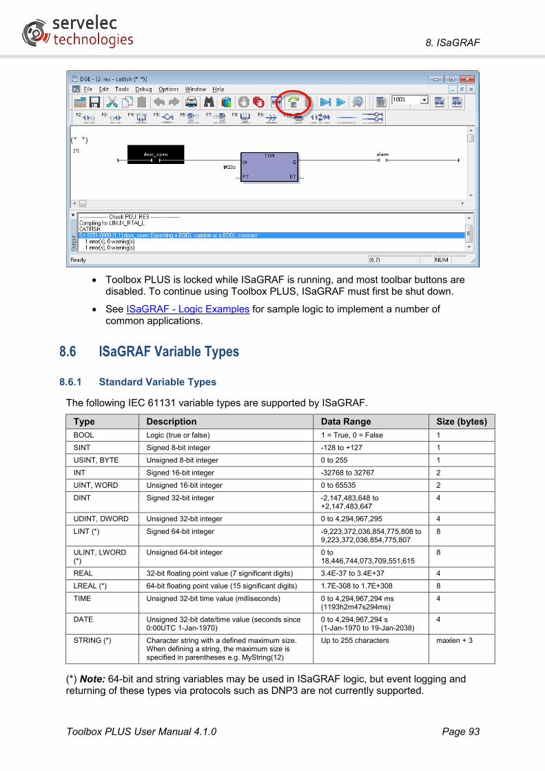
8. ISaGRAF
Toolbox PLUS User Manual 4.1.0 Page 93
• Toolbox PLUS is locked while ISaGRAF is running, and most toolbar buttons are
disabled. To continue using Toolbox PLUS, ISaGRAF must first be shut down.
• See ISaGRAF - Logic Examples for sample logic to implement a number of common applications.
8.6 ISaGRAF Variable Types
8.6.1 Standard Variable Types
The following IEC 61131 variable types are supported by ISaGRAF.
Type Description Data Range Size (bytes) BOOL Logic (true or false) 1 = True, 0 = False 1
SINT Signed 8-bit integer -128 to +127 1
USINT, BYTE Unsigned 8-bit integer 0 to 255 1
INT Signed 16-bit integer -32768 to 32767 2
UINT, WORD Unsigned 16-bit integer 0 to 65535 2
DINT Signed 32-bit integer -2,147,483,648 to +2,147,483,647
4
UDINT, DWORD Unsigned 32-bit integer 0 to 4,294,967,295 4
LINT (*) Signed 64-bit integer -9,223,372,036,854,775,808 to 9,223,372,036,854,775,807
8
ULINT, LWORD (*)
Unsigned 64-bit integer 0 to 18,446,744,073,709,551,615
8
REAL 32-bit floating point value (7 significant digits) 3.4E-37 to 3.4E+37 4
LREAL (*) 64-bit floating point value (15 significant digits) 1.7E-308 to 1.7E+308 8
TIME Unsigned 32-bit time value (milliseconds) 0 to 4,294,967,294 ms (1193h2m47s294ms)
4
DATE Unsigned 32-bit date/time value (seconds since 0:00UTC 1-Jan-1970)
0 to 4,294,967,294 s (1-Jan-1970 to 19-Jan-2038)
4
STRING (*) Character string with a defined maximum size. When defining a string, the maximum size is specified in parentheses e.g. MyString(12)
Up to 255 characters maxlen + 3
(*) Note: 64-bit and string variables may be used in ISaGRAF logic, but event logging and returning of these types via protocols such as DNP3 are not currently supported.

8. ISaGRAF
Toolbox PLUS User Manual 4.1.0 Page 94
8.6.2 Other Variable Types
The following array and structure types are also supported
Type Definition Description Size (bytes) TIMESTRUC DINT seconds High resolution date/time value, consisting of seconds since
0:00UTC 1-Jan-1970, plus a millisecond value (0-999) 8
INT millisec
IOPOINT_B BOOL value Structure type for holding a BOOL I/O point value, plus additional details such as timestamp and flags. See also IOPOINT types.
16
TIMESTRUC timestamp
USINT flags
USINT datatype
IOPOINT_D DINT value Structure type for holding a DINT I/O point value, plus additional details such as timestamp and flags. See also IOPOINT types.
16
TIMESTRUC timestamp
USINT flags
USINT datatype
IOPOINT_R REAL value Structure type for holding a REAL I/O point value, plus additional details such as timestamp and flags. See also IOPOINT types.
16
TIMESTRUC timestamp
USINT flags
USINT datatype
INT_ARRAY Array of 32 INT variables
Used for specifying Kingfisher register numbers or RTU addresses when using KF_RX_DATA, KF_TX_DATA, KF_NW_RX_DATA and KF_NW_TX_DATA function blocks.
64
EVENT_FILTER DINT value Used for specifying a filter when retrieving event logs using KF_RX_UPDATE_SINGLE and KF_RX_EVENT_LOGS function blocks: If all is set then all events are retrieved. Otherwise, if greater_equal_than is set then select events where the parameter >= value. Otherwise, if less_equal_than is set then select events where the parameter <= value. Otherwise, if equal is set then select events where the parameter = value.
8
BOOL all
BOOL greater_equal_than
BOOL less_equal_than
BOOL equal
DATA_TYPE USINT rtunet_usint Used for specifying a data value when using KF_SET_VARIABLE function block. Only one of these fields should be set. Note: rtunet_lreal is not implemented
296
SINT rtunet_sint
UINT rtunet_uint
INT rtunet_int
UDINT rtunet_udint
DINT rtunet_dint
REAL rtunet_real
LREAL rtunet_lreal
STRING(255) rtunet_string
DATE rtunet_date
TIME rtunet_time
Note that some structure definitions may include padding bytes between certain elements, resulting in the overall structure size, as indicated in the above table, being greater than the sum of its elements.

8. ISaGRAF
Toolbox PLUS User Manual 4.1.0 Page 95
8.6.3 IOPOINT Types
Data values originating from an I/O module or DNP3 are represented using IOPOINT_x types (IOPOINT_B for BOOL variables, IOPOINT_D for DINT and IOPOINT_R for REAL). These structures contain the following fields:
• value – the current value
• timestamp – (internal use only)
• datatype – (internal use only)
• flags – a set of 8 DNP3-format status bits. For I/O points (e.g. SL12DI10DI3), or DNP3 points which are mapped to I/O points, the following read-only bits may be set by the RTU:
Bit Name Description 0 ONLINE I/O module is present and working correctly 1 - 2 - 3 - 4 - 5 OVER_RANGE Value is over-range (analog input points only) 6 - 7 STATE Copy of value (digital input points only)
For DNP3 points which are not mapped to I/O, the following read/write bits are defined.
Bit Name Description 0 ONLINE 1 RESTART 2 COMM_LOST 3 REMOTE_FORCED 4 LOCAL_FORCED 5 OVER_RANGE /
CHATTER
6 REF ERROR / DISCONTINUITY / SELECTED
SELECTED is set when a DNP3 SELECT command is received, and cleared when an OPERATE command is received or a Select timeout occurs (slave only, binary output points only)
7 STATE STATE is set to the value written when a WRITE or OPERATE command is received (slave only, binary output points only)
When operating as a slave, the RTU may set the STATE and SELECTED bits, as indicated above. When the RTU is a master, if status information was returned by the downstream device then all bits will be copied to the flags field.
Note: If you set the value field of a DNP3 variable in logic, then by default all other fields will be zero. This means that when the master system polls the variable, it will generally mark the value as “bad” or “offline”, because the ONLINE bit is not set. To rectify this, set the flags field in logic as well. For example:

8. ISaGRAF
Toolbox PLUS User Manual 4.1.0 Page 96
8.7 ISaGRAF Constants Constant values should be specified as follows:
Type Sample Constants Description BOOL TRUE, FALSE Boolean value
Integer types 0, -5, 20000 Decimal (base 10) value
16#2CFF Hexadecimal (base 16) value
2#0011_1110 Binary (base 2) value
DNP_CLASS_1, ROUTE_DIRECT Defined words representing particular integer values (refer to function block definitions)
Floating point (Real) types
0.0, 3.1415, -2.0 Decimal format, must include decimal point
1.0E-3, 9.222e6, -2.1e+8 Exponential format, must include decimal point
TIME T#0s, T#1m30s, T#90m, T#800ms Time unit symbols are: d, h, m, s, ms
DATE D#2013-3-28 Year-month-day
STRING 'cats and dogs' 'dollar$$ and newline$N' 'tab$09'
Enclose strings in single quotes Prefix special characters with $: $$ – $ character $N – newline (CR,LF) $T – tab character $’ – apostrophe character $nn – ASCII character nn (hexadecimal) Note: String constants entered in the Ladder Diagram editor will be converted to uppercase.
The following Defined Words (symbolic constants) can be used instead of numeric constants.
Defined Word Value Used for Function Blocks PROTOCOL_KINGFISHER 1 KF_GET_ROUTE, KF_SET_ROUTE,
KF_GET_PENDING, KF_CLEAR_PENDING PROTOCOL_DNP3 8
PROTOCOL_SNMPC 12
PROTOCOL_MODBUS_ASCII 14
PROTOCOL_MODBUS_RTU 15
PROTOCOL_MODBUS_TCP 16
PROTOCOL_AB 18
PROTOCOL_HART 19
PROTOCOL_SMS 30
DNP_CLASS_0 1 DNPM_CLASS_POLL, DNPM_UNSOL_ENABLE, DNPM_UNSOL_DISABLE, DNPS_UNSOL_ENABLE, DNPS_UNSOL_DISABLE
DNP_CLASS_1 2
DNP_CLASS_2 4
DNP_CLASS_3 8
DNP_CTRL_PULSE_ON 1 DNPM_BINARY_COMMAND
DNP_CTRL_PULSE_OFF 2

8. ISaGRAF
Toolbox PLUS User Manual 4.1.0 Page 97
DNP_CTRL_LATCH_ON 3
DNP_CTRL_LATCH_OFF 4
DNP_AUTO_NONE 0 DNPM_BINARY_COMMAND, DNPM_ANALOG_16BIT_COMMAND, DNPM_ANALOG_32BIT_COMMAND, DNPM_ANALOG_FLOAT_COMMAND
DNP_AUTO_OPERATE 1
DNP_AUTO_FEEDBACK 2
DNP_FC_SELECT 3 DNPM_BINARY_COMMAND, DNPM_ANALOG_16BIT_COMMAND, DNPM_ANALOG_32BIT_COMMAND, DNPM_ANALOG_FLOAT_COMMAND
DNP_FC_OPERATE 4
DNP_FC_DIRECT 5
ROUTE_DIRECT 0 KF_GET_ROUTE, KF_SET_ROUTE
ROUTE_INDIRECT 1
SNMP_BOOLEAN 1 SNMP_SET_VALUE
SNMP_INTEGER 2
SNMP_BITSTRING 3
SNMP_OCTETSTRING 4
SNMP_NULL 5
SNMP_OBJECTID 6
SNMP_IPADDRESS 64
SNMP_COUNTER 65
SNMP_GAUGE 66
SNMP_TIMETICKS 67
SNMP_OPAQUE 68
SNMP_NSAP 69
SNMP_UINTEGER 71
SMS_CYBERTEC_2220W 'sms send %n "%t"' SEND_SMS
SMS_NETCOMM_4G_M2M 'sendsms "%n" "%t"'
SMS_MAXON_EM_770W_UNI 'echo "%n, %t"> /var/tmp/cmdsndsms1'
8.8 ISaGRAF Reserved Names Listed below are the names that are reserved by ISaGRAF 5.xx and so cannot be used as variable names. In addition, all names beginning with the underscore character are reserved.
A ABS, ACOS, ADD, ANA, AND, AND_MASK, ANDN, ARRAY, ASIN, AT, ATAN
B BCD_TO_BOOL, BCD_TO_INT, BCD_TO_REAL, BCD_TO_STRING, BCD_TO_TIME, BOO, BOOL, BOOL_TO_BCD, BOOL_TO_INT, BOOL_TO_REAL, BOOL_TO_STRING, BOOL_TO_TIME, BY, BYTE
C CAL, CALC, CALCN, CALN, CALNC, CASE, CONCAT, CONSTANT, COS
D DATE, DATE_AND_TIME, DELETE, DINT, DIV, DO, DT, DWORD
E ELSE, ELSIF, EN, END_CASE, END_FOR, END_FUNCTION, END_IF, END_PROGRAM, END_REPEAT, END_RESOURCE, END_STRUCT, END_TYPE, END_VAR, END_WHILE, ENO, EQ, EXIT, EXP, EXPT
F FALSE, FIND, FOR, FUNCTION
G GE, GFREEZE, GKILL, GRST, GSTART, GSTATUS, GT
I IF, INSERT, INT, INT_TO_BCD, INT_TO_BOOL, INT_TO_REAL, INT_TO_STRING, INT_TO_TIME
J JMP, JMPC, JMPCN, JMPN, JMPNC
L LD, LDN, LE, LEFT, LEN, LIMIT, LINT, LN, LOG, LREAL, LT, LWORD
M MAX, MID, MIN, MOD, MOVE, MSG, MUL, MUX
N NE, NOT
O OF, ON, OR, OR_MASK, ORN
P R, READ_ONLY, READ_WRITE, REAL, REAL_TO_BCD, REAL_TO_BOOL, REAL_TO_INT, REAL_TO_STRING, REAL_TO_TIME, REPEAT, REPLACE, RESSOURCE, RET, RETAIN, RETC, RETCN, RETN, RETNC, RETURN, RIGHT, ROL, ROR
S S, SEL, SHL, SHR, SIN, SINT, SQRT, ST, STN, STRING, STRING_TO_BCD, STRING_TO_BOOL,

8. ISaGRAF
Toolbox PLUS User Manual 4.1.0 Page 98
STRING_TO_INT, STRING_TO_REAL, STRING_TO_TIME, STRUCT, SUB, SUB_DATE_DATE, SYS_ERR_READ, SYS_ERR_TEST, SYS_INITALL, SYS_INITANA, SYS_INITBOO, SYS_INITTMR, SYS_RESTALL, SYS_RESTANA, SYS_RESTBOO, SYS_RESTTMR, SYS_SAVALL, SYS_SAVANA, SYS_SAVBOO, SYS_SAVTMR, SYS_TALLOWED, SYS_TCURRENT, SYS_TMAXIMUM, SYS_TOVERFLOW, SYS_TRESET, SYS_TWRITE, SYSTEM
T TAN, TASK, THEN, TIME, TIME_OF_DAY, TIME_TO_BCD, TIME_TO_BOOL, TIME_TO_INT, TIME_TO_REAL, TIME_TO_STRING, TMR, TO, TOD, TRUE, TYPE
U UDINT, UINT, ULINT, UNTIL, USINT
V VAR, VAR_ACCESS, VAR_EXTERNAL, VAR_GLOBAL, VAR_IN_OUT, VAR_INPUT, VAR_OUTPUT
W WHILE, WITH, WORD
X XOR, XOR_MASK, XORN
8.9 ISaGRAF Licensing Details To use ISaGRAF workbench beyond the 30 day trial period, a Sentinel USB licence key is
required (pictured left). This should be plugged into a USB port on your computer before starting ISaGRAF.
The licence keys differ in cost and functionality based on the number of usable I/O points. Options include 64, 256, 1024 or unlimited I/O points, or a restricted personal maintenance key that cannot compile programs.
When purchasing a licence key, the size of the RTU to be implemented needs to be considered.
The I/O point limit effectively constrains the number of readable and settable registers available to Toolbox PLUS and ISaGRAF. Note that unused variables can be deleted from the dictionary to save on licence I/O slots.
For example, a system comprising of a PS-1x, CP-30 and an IO-3 uses 31 I/O points, as follows:
Module I/O Type I/O Function No. Of Variables
PS-1x Analog Inputs 1 to 7 Current and Voltage measurement
7
Digital Inputs 1 to 8 Charge States and Flags 8 Digital Outputs 1 to 3 Power Control 3
IO-3 Analog Inputs 1 to 4 Misc Analog Input 4 Analog Output 1 Misc Analog Output 1 Digital Inputs 1 to 4 Misc Digital Inputs 4 Digital Outputs 1 to 4 Misc Digital Output 4
Total: 31
If this system was not required to monitor any power usage or facilitate a backup battery, the variables assigned to the PS-1x can be removed, freeing up 18 I/O points.
For additional information on specific variables on each module, see RTU Variables.

9. ISaGRAF Function Blocks
Toolbox PLUS User Manual 4.1.0 Page 99
9. ISaGRAF Function Blocks A number of protocols and special functions have been implemented using custom ISaGRAF function blocks as detailed below.
Category Function Block Description Kingfisher protocol KF_RX_DATA Read Kingfisher registers from a remote RTU
KF_TX_DATA Send Kingfisher registers to a remote RTU
KF_NW_RX_DATA Read Kingfisher network registers from a remote RTU
KF_NW_TX_DATA Send Kingfisher network registers to a remote RTU
KF_RX_UPDATE_SINGLE Read data/events from a Series 2 RTU
KF_GET_VARIABLE Read a variable from a remote RTU
KF_SET_VARIABLE Update a variable on a remote RTU
KF_RX_EVENT_LOGS Read events from a remote RTU
KF_TX_EVENT_LOGS Send events to a remote RTU
DNP3 protocol DNPM_CLASS_POLL Read data (selected classes) from slave device
DNPM_INTEGRITY_POLL Read data (all classes) from slave device
DNPM_READ_GROUP Read data (selected types) from slave device
DNPM_ANALOG_16BIT_COMMAND Set analog value on slave device
DNPM_ANALOG_32BIT_COMMAND Set analog value on slave device
DNPM_ANALOG_FLOAT_COMMAND Set analog value on slave device
DNPM_BINARY_COMMAND Set binary value on slave device
DNPM_FREEZE_COUNTERS Record snapshot of counter values on slave device
DNPM_UNSOL_ENABLE Enable unsolicited reporting by slave device
DNPM_UNSOL_DISABLE Disable unsolicited reporting by slave device
DNPM_COLD_RESTART Restart slave device
DNPM_WARM_RESTART Restart slave device
DNPM_CLEAR_RESTART Clear Device Restart IIN bit on slave device
DNPM_LINK_RESET Reset comms link
DNPM_TIME_SYNC Set time in slave device
DNPS_NEED_TIME Set Need Time IIN bit
DNPS_UNSOL_ENABLE Enable unsolicited reporting
DNPS_UNSOL_DISABLE Disable unsolicited reporting
Modbus protocol MODBUS Read/write data to/from slave Modbus device
Allen Bradley DF1 protocol
ABDF1_RX Read data from Allen Bradley PLC
ABDF1_TX Write data to Allen Bradley PLC
HART protocol HART Read/write data to/from slave HART device
SNMP Client protocol
SNMP_GET_INT Read integer from remote device
SNMP_GET_UINT Read unsigned integer from remote device
SNMP_GET_STRING Read string from remote device
SNMP_GET_OBJID Read OID string from remote device
SNMP_GET_BULK Read multiple values from remote device
SNMP_SET_INT Write integer to remote device
SNMP_SET_UINT Write unsigned integer to remote device
SNMP_SET_STRING Write string to remote device
SNMP_SET_OBJID Write OID string to remote device
SNMP_SET_VALUE Write value of any type to remote device
SNMP Trap protocol SNMP_GET_TRAP Read received trap message

9. ISaGRAF Function Blocks
Toolbox PLUS User Manual 4.1.0 Page 100
SNMP_SEND_TRAP Send trap message
SNMP RMS protocol SNMPRMS Send RMS Systems trap message
User Defined protocol
USER_TX Send bytes to remote device
USER_RX Read bytes received from remote device
USER_RX_BYTES Return number of received bytes
SMS protocol SEND_SMS Send SMS message
PHONE_TO_STRING Convert integer phone number to string
VRRP protocol VRRP Return VRRP status
General Communications
KF_GET_COMM_STATS Get comms statistics for one or all RTUs
KF_RESET_COMM_STATS Clear comms statistics for one or all RTUs
KF_GET_PORT_STATS Get comms statistics for a physical port
KF_RESET_PORT_STATS Clear comms statistics for a physical port
KF_GET_PENDING Indicates whether a message is in progress
KF_CLEAR_PENDING Clear the message pending flag
KF_GET_ROUTE Get information about the route to a remote RTU
KF_SET_ROUTE Modify the route to a remote RTU
Event Logging KF_EVENT_LOG Store an event log
KF_CLEAR_EVENT_LOGS Clear all event logs on local or remote RTU
KF_GET_EVENT_LOG_COUNT Get event log count on local or remote RTU
RTU System Data KF_GET_ADDRESS Return RTU address
KF_GET_FIRMWARE Return RTU firmware version
KF_GET_RTU_TYPE Return RTU type
KF_GET_SYSTEMID Return system ID byte
KF_GET_PROCESSOR Return processor backplane slot
KF_GET_MODULE_TYPE Return module type in specified slot
KF_GET_MODULE_OK Check whether slot contains expected module
KF_RESET_MODULE Reset/reconfigure module
REBOOT Reboot processor module
KF_GET_RTC Get current time as integer
KF_SET_RTC Set current time as integer
KF_GET_TIME Get current time as separate components
KF_SET_TIME Set current time as separate components
GET_BP12V Return 12V rail voltage
GET_LOWBATT Return Li battery failure status
SET_BPFIELD Control I/O field power
SET_BPAUX Control powered backplane AUX output
Maths & Logic INCREMENT Increment a value
DECREMENT Decrement a value
ChangeDetect Detect change in a value
MulDiv Scale a floating point value
MULDIV_INT Scale an integer value
BCD_TO_BINARY Convert BCD to integer
BINARY_TO_BCD Convert integer to BCD
FPACK Join two integers to make floating point value
FUNPACK Split floating point value into two integers
F64PACK Join four integers to make a 64-bit floating point value
F64UNPACK Split 64-bit floating point value into four integers
U32PACK Join two 16-bit integers to make a 32-bit value
U32UNPACK Split 32-bit value into two 16-bit integers
U64PACK Join four 16-bit integers to make a 64-bit value

9. ISaGRAF Function Blocks
Toolbox PLUS User Manual 4.1.0 Page 101
U64UNPACK Split 64-bit value into four 16-bit integers
NBIT Set/clear single bit
NCBT Test single bit for 1
NOBT Test single bit for 0
PID Controller KF_PID Proportional Integral Derivative Controller
Gas Flow Calculations
AGA3 Calculate gas mass flow
AGA5 Calculate gas heating value
AGA7 Calculate gas volumetric flow
AGA8_GROSS Calculate gas compressibility
AGA8_DETAILED Calculate gas compressibility
AGA11 Calculate gas volumetric flow (Coriolis meter)
GBT17747_2 Calculate gas compressibility (Chinese standard)
GBT21446 Calculate gas flow rate (Chinese standard)
These function blocks are shown in Ladder Diagram form. However they can be used in any of the languages supported by ISaGRAF.
Note: The EN (Enable) and ENO (Enable Out) parameters on each function block are only present when the block is used in a Ladder Diagram program. The function block will be executed every cycle, while the EN input is true. The state of EN is copied to the ENO output.
See ISaGRAF - Logic Examples for some practical examples of using these function blocks.
Note that there are some function blocks listed in ISaGRAF which are no longer supported and should not be used. See Obsolete Function Blocks for more details.

9. ISaGRAF Function Blocks
Toolbox PLUS User Manual 4.1.0 Page 102
9.1 Kingfisher Protocol The following function blocks are used to initiate Kingfisher protocol operations.
A Kingfisher register variable must be created in the Dictionary for every point that you wish to transfer using Kingfisher protocol.
If the RTU is operating as a slave device then it is not necessary to call these function blocks. Simply load the required values into local Kingfisher registers (KFRn), either by mapping them to I/O module points or by setting them in logic.
9.1.1 KF_RX_DATA
Polls a remote RTU for up to 32 Kingfisher register values. Registers KFRn on the remote RTU#r will be transferred to registers KFrRn on the local RTU.
This is typically used where a master RTU periodically polls an outstation.
Parameter Type Description RTU UINT Address of RTU from which to read data (1-65520) REG INT_ARRAY Array of up to 32 INT values specifying the register numbers (1-2048) to
read. NBR USINT Number of registers to read (1-32) ERR DINT Status output (0=OK, -34=one or more parameters out of range)
For example, to update registers KF10R1, KF10R2 and KF10R75 (by polling RTU #10), then you would set RTU=10, NBR=3 and then create an INT_ARRAY variable to specify the three register numbers. This is done from the ISaGRAF Dictionary page. Set the initial values of the array elements as follows:
Then specify the name of the array (RTU10regs in this example) for the function block REG parameter.

9. ISaGRAF Function Blocks
Toolbox PLUS User Manual 4.1.0 Page 103
9.1.2 KF_TX_DATA
Sends up to 32 Kingfisher local register variables to a remote RTU. Registers KFRn on the local RTU will be transferred to registers KFrRn on the remote RTU (where r is the address of the local RTU).
This is typically used for exception reporting, where an outstation reports values to a master when it detects that a change has occurred. It may also be used by a master to update control values on an outstation.
Parameter Type Description RTU UINT Address of RTU to send to (1-65520) REG INT_ARRAY Array of up to 32 INT values specifying the register numbers (1-2048) to
send. NBR USINT Number of registers to send (1-32) ERR DINT Status output (0=OK, -34=one or more parameters out of range)
For example, to send the values of registers KFR1, KFR2 and KFR75 to an RTU with address 10, you would set RTU=10, NBR=3 and then create an INT_ARRAY variable to specify the three register numbers, as described in KF_RX_DATA.

9. ISaGRAF Function Blocks
Toolbox PLUS User Manual 4.1.0 Page 104
9.1.3 KF_NW_RX_DATA
Polls a remote RTU for up to 32 Kingfisher register values, which may have originated from other RTUs. Registers KFrRn on the remote RTU will be transferred to registers KFrRn on the local RTU.
This is typically used where a master RTU periodically polls a concentrator RTU, which in turn polls various outstation RTUs.
Parameter Type Description RTU UINT Address of RTU from which to read data (1-65520) REG INT_ARRAY Array of up to 32 INT values specifying the register numbers (1-2048) to
read. NRTU INT_ARRAY Array of up to 32 INT values specifying the source RTU (1-249) for each
of the registers to read. NBR USINT Number of registers to read (1-32) ERR DINT Status output (0=OK, -34=one or more parameters out of range)
For example, suppose RTU #10 is set up to poll RTU #2 and RTU #3. To read and update network registers KF2R1, KF2R2, KF2R42, KF3R1 and KF3R101 (by polling RTU #10) you would set RTU=10 and NBR=5.
Then create an INT_ARRAY variable to specify the five register numbers, and another INT_ARRAY to specify the source RTU address for each of these five registers. This is done from the ISaGRAF Dictionary page. Set the initial values of the array elements as follows:
Then specify the names of the arrays (RTU10regs and RTU10addresses in this example) for the function block REG and NRTU parameters.

9. ISaGRAF Function Blocks
Toolbox PLUS User Manual 4.1.0 Page 105
9.1.4 KF_NW_TX_DATA
Sends up to 32 Kingfisher network register variables to a remote RTU. Registers KFrRn on the local RTU will be transferred to registers KFrRn on the remote RTU.
This is typically used for exception reporting, where a concentrator RTU reports values received from one or more outstations to a master RTU.
Parameter Type Description RTU UINT Address of RTU to send to (1-65520) REG INT_ARRAY Array of up to 32 INT values specifying the register numbers (1-2048) to
send. NRTU INT_ARRAY Array of up to 32 INT values specifying the source RTU (1-249) for each
of the registers to send. NBR USINT Number of registers to send (1-32) ERR DINT Status output (0=OK, -34=one or more parameters out of range)
For example, to send the network registers KF2R1, KF2R2, KF2R42, KF3R1 and KF3R101 to RTU #1 you would set RTU=1 and NBR=5.
Then create an INT_ARRAY variable to specify the five register numbers, and another INT_ARRAY to specify the source RTU address for each of these five registers, as described in KF_NW_RX_DATA.
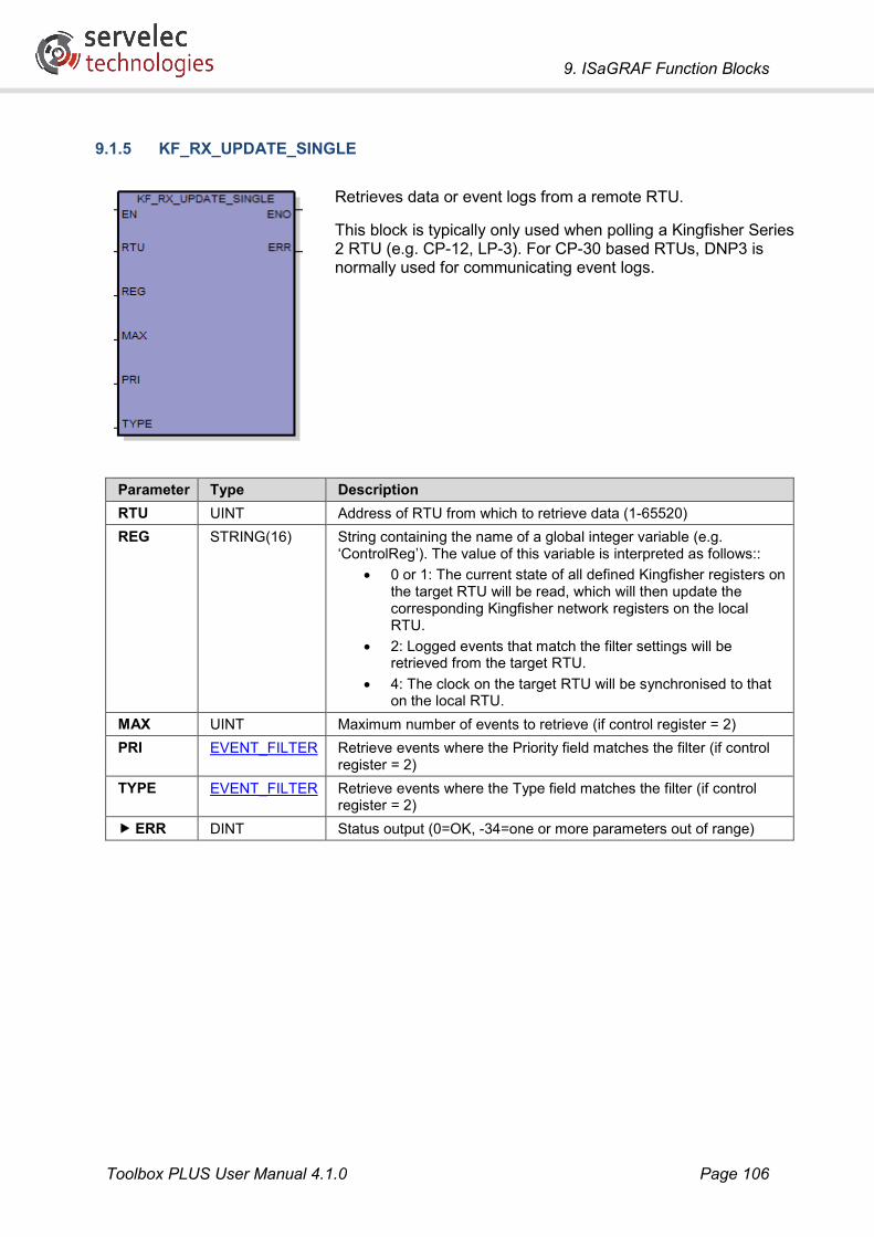
9. ISaGRAF Function Blocks
Toolbox PLUS User Manual 4.1.0 Page 106
9.1.5 KF_RX_UPDATE_SINGLE
Retrieves data or event logs from a remote RTU.
This block is typically only used when polling a Kingfisher Series 2 RTU (e.g. CP-12, LP-3). For CP-30 based RTUs, DNP3 is normally used for communicating event logs.
Parameter Type Description RTU UINT Address of RTU from which to retrieve data (1-65520) REG STRING(16) String containing the name of a global integer variable (e.g.
‘ControlReg’). The value of this variable is interpreted as follows:: • 0 or 1: The current state of all defined Kingfisher registers on
the target RTU will be read, which will then update the corresponding Kingfisher network registers on the local RTU.
• 2: Logged events that match the filter settings will be retrieved from the target RTU.
• 4: The clock on the target RTU will be synchronised to that on the local RTU.
MAX UINT Maximum number of events to retrieve (if control register = 2) PRI EVENT_FILTER Retrieve events where the Priority field matches the filter (if control
register = 2) TYPE EVENT_FILTER Retrieve events where the Type field matches the filter (if control
register = 2) ERR DINT Status output (0=OK, -34=one or more parameters out of range)

9. ISaGRAF Function Blocks
Toolbox PLUS User Manual 4.1.0 Page 107
9.1.6 KF_GET_VARIABLE
Retrieves a variable by name from a remote Kingfisher RTU.
Parameter Type Description RTU UINT Address of RTU from which to retrieve variable (1-65520) TYP USINT Data type of variable:
1=USINT, 2=SINT, 3=UINT, 4=INT, 5=UDINT, 6=DINT, 7=REAL, 9=STRING, 10=DATE, 11=TIME.
NAM STRING(16) Name of global variable on remote RTU to retrieve. DEST STRING(16) Name of global variable on local RTU to write value to. ERR DINT Status output (0=OK, -34=one or more parameters out of range)
9.1.7 KF_SET_VARIABLE
Sets the value of a variable on a remote Kingfisher RTU.
Parameter Type Description RTU UINT Address of RTU to write to (1-65520) TYP USINT Data type of variable:
1=USINT, 2=SINT, 3=UINT, 4=INT, 5=UDINT, 6=DINT, 7=REAL, 9=STRING, 10=DATE, 11=TIME.
NAM STRING(16) Name of global variable on remote RTU to set. VAL DATA_TYPE Value to set ERR DINT Status output (0=OK, -34=one or more parameters out of range)

9. ISaGRAF Function Blocks
Toolbox PLUS User Manual 4.1.0 Page 108
9.1.8 KF_RX_EVENT_LOGS
Retrieves event logs that occurred over a specific time period from a remote RTU. It will keep polling event logs until it has received the maximum limit of logs or until the end of the event log list is reached.
This block is typically only used when polling a Kingfisher Series 2 RTU (e.g. CP-12, LP-3). For CP-30 based RTUs, DNP3 is normally used for communicating event logs.
Parameter Type Description RTU UINT Address of RTU from which to retrieve logs (1-65520) STAT STRING(16) String containing the name of a global integer variable (e.g.
‘StatusReg’). Will be updated, but not with anything useful. TIME UDINT Start time of the first event log to receive (minutes before now). PRD UDINT Time period of event logs to receive (minutes). MAX UINT Maximum number of event logs to retrieve FRTU UINT If non-zero, only events matching the event filters below will be
returned. PRI EVENT_FILTER Retrieve events where the Priority field matches the filter UTYP EVENT_FILTER Retrieve events where the Type field matches the filter ERR DINT Status output (0=OK, non-zero if error)
Note: If the remote RTU address is less than 256 then a “Series 2” event log request is performed. This will only return events relating to Kingfisher registers and I/O module points. If the RTU address is greater than or equal to 256 then a “Series 3” request is sent, which will return all event logs.

9. ISaGRAF Function Blocks
Toolbox PLUS User Manual 4.1.0 Page 109
9.1.9 KF_TX_EVENT_LOGS
Sends event logs to a remote RTU.
This block is typically only used when sending data to a Kingfisher Series 2 RTU (e.g. CP-12, LP-3). For CP-30 based RTUs, DNP3 is normally used for communicating event logs.
Parameter Type Description RTU UINT Address of destination RTU (1-65520) EPTR STRING(16) String containing the name of a global integer variable (e.g.
‘EventPtr’). This variable contains the index of the first event log to send, and will be automatically updated on completion of the function block.
STAT STRING(16) String containing the name of a global integer variable (e.g. ‘StatusReg’). Set to 128 if an error occurs, set to 1 when transmission is complete.
NBR UINT Maximum number of event logs to send. ERR DINT Status output (0=OK, non-zero if parameter error)
Note: If the remote RTU address is less than 256 then a “Series 2” event log request is performed. Only events relating to Kingfisher registers and I/O module points will be sent. If the RTU address is greater than or equal to 256 then a “Series 3” request is sent, which will send all event logs.

9. ISaGRAF Function Blocks
Toolbox PLUS User Manual 4.1.0 Page 110
9.2 DNP3 Protocol The following function blocks are used to initiate DNP3 protocol operations.
Function blocks with names beginning with DNPM_ are used when the RTU is operating as a DNP3 master, while DNPS_ function blocks are used when the RTU is operating as a DNP3 slave.
A DNP3 variable must be created in the Dictionary for every point that you wish to transfer using the DNP3 protocol.
If the RTU is operating as a slave device then it is not necessary to call these function blocks. Simply load the required values into local DNP3 registers (DNPBIn, DNPAIn etc.), either by mapping them to I/O module points or by setting them in logic.
9.2.1 DNPM_CLASS_POLL
Polls a remote DNP3 device for static values (class 0 data) and/or events (class 1/2/3 data).
Returned object data will be stored in the local RTU if DNP3 variables (e.g. DNPrBIn for binary inputs) have been created in the Dictionary.
Parameter Type Description ADDR UINT Address of slave device from which to read data (1-65535) MASK USINT Bitmask specifying class(es) of data to read (0-15):
bit0=Class 0, bit1=Class 1, bit2=Class 2, bit3=Class 3. If a single class is being read then the defined words DNP_CLASS_0, DNP_CLASS_1, DNP_CLASS_2 or DNP_CLASS_3 may also be used.
For example, to read the current states of all DNP3 variables (i.e. class 0 data) and all class 1 events from a DNP3 device with address 3008 then you would set ADDR=3008 and MASK=3. If a variable DNP3008BI22 was defined on the local RTU then its value would be updated (assuming that DNP Binary Input #22 was defined on the slave device). If the variable was defined as class 1, then any events received from the device relating to this variable would be logged.
Any received static (class 0) data for which DNP3 variables are not defined will be discarded.
Note: The DNP3 protocol does not transmit class information along with each event. When DNP3 events are received and logged by the RTU, the event logs will each be tagged with the lowest event class number that was requested (1, 2 or 3). This means that if multiple classes of DNP3 events are requested simultaneously, then the class number that will be attached to the event logs will not necessarily match that of the original point on the remote source RTU.
This can be important where the RTU is operating as a concentrator, i.e polling slave DNP3 devices and in turn being polled by a DNP3 master.

9. ISaGRAF Function Blocks
Toolbox PLUS User Manual 4.1.0 Page 111
For example, suppose a remote slave device contains two DNP3 points DNPBI101 (class 1) and DNPBI102 (class 2). If the RTU performs a Class 1+2 poll (MASK=6) then all events for both these points will be logged as Class 1 events. If a master system then issues a Class 2 poll to the RTU, events for DNPBI102 will not be returned.
If you wish to preserve the original point’s class in the event log then separate class 1, 2 and 3 polls should be performed. Likewise, the DNPM_INTEGRITY_POLL function block (which performs a Class 0+1+2+3 poll) should not be used.
9.2.2 DNPM_INTEGRITY_POLL
Polls a remote DNP3 device for static values (class 0 data) and events (class 1/2/3 data). Equivalent to calling DNPM_CLASS_POLL with MASK=15.
Parameter Type Description ADDR UINT Address of slave device from which to read data (1-65535)
Note: Events logged by the RTU using this function block will all be marked as Class 1 events, which may not be desirable in situations where the RTU is in turn being polled by a master system. See DNPM_CLASS_POLL for more information.
9.2.3 DNPM_READ_GROUP
Polls a remote DNP3 device for static values (class 0 data) of a particular type.
Parameter Type Description ADDR UINT Address of slave device from which to read data (1-65535) GRP USINT Data type group to poll:
1=binary inputs, 10=binary outputs, 20=binary counters, 21=frozen counters, 30=analog inputs, 40=analog outputs
ERR UINT Status output (0=OK, 65535=one or more parameters out of range)
For example, if ADDR is set to 205 and GRP is set to 30 then analog input variables (DNP205AInn) would be updated.

9. ISaGRAF Function Blocks
Toolbox PLUS User Manual 4.1.0 Page 112
9.2.4 DNPM_ANALOG_16BIT_COMMAND
Sets a 16-bit (UINT) DNP3 variable on a slave device.
Parameter Type Description ADDR UINT Address of slave device containing the variable to set (1-65535) FC USINT Specifies the function to perform:
3=Select, 4=Operate, 5=Direct Operate The defined words DNP_FC_SELECT, DNP_FC_OPERATE and DNP_FC_DIRECT may also be used. See DNP3 Select and Operate for more information.
AUTO USINT Specifies whether the above function should be automatically followed by the appropriate confirmation function. 0=None, 1=Automatic Operate after Select, 2=Automatic Feedback Poll after Operate The defined words DNP_AUTO_NONE, DNP_AUTO_OPERATE and DNP_AUTO_FEEDBACK may also be used. See DNP3 Select and Operate for more information.
OPER UDINT If an automatic feedback poll is selected, this parameter specifies the delay (ms) between the Operate and the feedback poll.
PNT UINT DNP3 analog point number (0-65535) VAL UINT Value to set
DNP3 Select and Operate
The DNP3 protocol provides an option to set control outputs using a two stage confirmation process. First, a Select message is sent which specifies the desired state(s). If a valid acknowledgement is received from the slave then an Operate message containing identical data is sent, which the slave will then action.
If this confirmation procedure is not required then a single Direct Operate message can be used. The master can then optionally poll the outputs to verify that they were set.
The following combinations of the FC and AUTO function block parameters may be used:

9. ISaGRAF Function Blocks
Toolbox PLUS User Manual 4.1.0 Page 113
FC AUTO Action DNP_FC_SELECT DNP_AUTO_NONE Send Select message
DNP_FC_SELECT DNP_AUTO_OPERATE Send Select message. If valid response from slave then send Operate message.
DNP_FC_OPERATE DNP_AUTO_NONE Send Operate message
DNP_FC_OPERATE DNP_AUTO_FEEDBACK Send Operate message. Wait for specified delay, then send Feedback Poll message.
DNP_FC_DIRECT DNP_AUTO_NONE Send Direct Operate message
DNP_FC_DIRECT DNP_AUTO_FEEDBACK Send Direct Operate message. Wait for specified delay, then send Feedback Poll message.
9.2.5 DNPM_ANALOG_32BIT_COMMAND
Sets a 32-bit (UDINT) DNP3 variable on a slave device.
Same as DNPM_ANALOG_16BIT_COMMAND, apart from the type of the VAL parameter.
9.2.6 DNPM_ANALOG_FLOAT_COMMAND
Sets a 32-bit floating point (REAL) DNP3 variable on a slave device.
Same as DNPM_ANALOG_16BIT_COMMAND, apart from the type of the VAL parameter.

9. ISaGRAF Function Blocks
Toolbox PLUS User Manual 4.1.0 Page 114
9.2.7 DNPM_BINARY_COMMAND
Sets a binary (BOOL) DNP3 variable on a slave device.
Parameter Type Description ADDR UINT Address of slave device containing the variable to set (1-65535) FC USINT Specifies the function to perform, as per
DNPM_ANALOG_16BIT_COMMAND AUTO USINT Specifies the automatic confirmation function, as per
DNPM_ANALOG_16BIT_COMMAND OPER UDINT Specifies the delay before performing an automatic feedback poll, as per
DNPM_ANALOG_16BIT_COMMAND PNT UINT DNP3 binary point number (0-65535) CTRL USINT Binary control function to perform:
1=Pulse On, 2=Pulse Off, 3=Latch On, 4=Latch Off The defined words DNP_CTRL_PULSE_ON, DNP_CTRL_PULSE_OFF, DNP_CTRL_LATCH_ON and DNP_CTRL_LATCH_OFF may also be used.
ON UDINT If Pulse On is selected, this specifies the pulse on time (ms). OFF UDINT If Pulse Off is selected, this specifies the pulse off time (ms).

9. ISaGRAF Function Blocks
Toolbox PLUS User Manual 4.1.0 Page 115
9.2.8 DNPM_FREEZE_COUNTERS
Freezes the counters in a slave device, i.e. takes a snapshot of their current count values. Additionally it allows the counters to be cleared after being frozen.
Parameter Type Description ADDR UINT Address of slave device containing the counter variables (1-65535) CLR BOOL If true then the counters will be cleared after being frozen.
9.2.9 DNPM_UNSOL_ENABLE
Commands a slave device to enable unsolicited responses.
Parameter Type Description ADDR UINT Address of slave device (1-65535) MASK USINT Bitmask specifying class(es) of data for which to enable unsolicited
responses (0-7): bit0=Class 1, bit1=Class 2, bit2=Class 3.
9.2.10 DNPM_UNSOL_DISABLE
Commands a slave device to disable unsolicited responses.
Parameter Type Description ADDR UINT Address of slave device (1-65535) MASK USINT Bitmask specifying class(es) of data for which to disable unsolicited
responses (0-7): bit0=Class 1, bit1=Class 2, bit2=Class 3.

9. ISaGRAF Function Blocks
Toolbox PLUS User Manual 4.1.0 Page 116
9.2.11 DNPM_COLD_RESTART
Commands a slave device to perform a cold restart.
Note that a slave Kingfisher RTU does not distinguish between cold and warm restarts: both requests will cause a reboot.
Parameter Type Description ADDR UINT Address of slave device (1-65535)
9.2.12 DNPM_WARM_RESTART
Commands a slave device to perform a warm restart.
Note that a slave Kingfisher RTU does not distinguish between cold and warm restarts: both requests will cause a reboot.
Parameter Type Description ADDR UINT Address of slave device (1-65535)
9.2.13 DNPM_CLEAR_RESTART
Resets the DEVICE_RESTARTED bit in a slave device’s Internal Indications (IIN) register.
Parameter Type Description ADDR UINT Address of slave device (1-65535)
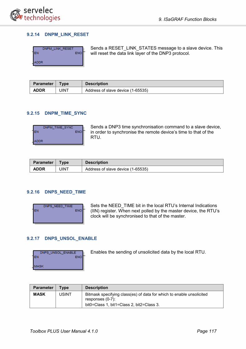
9. ISaGRAF Function Blocks
Toolbox PLUS User Manual 4.1.0 Page 117
9.2.14 DNPM_LINK_RESET
Sends a RESET_LINK_STATES message to a slave device. This will reset the data link layer of the DNP3 protocol.
Parameter Type Description ADDR UINT Address of slave device (1-65535)
9.2.15 DNPM_TIME_SYNC
Sends a DNP3 time synchronisation command to a slave device, in order to synchronise the remote device’s time to that of the RTU.
Parameter Type Description ADDR UINT Address of slave device (1-65535)
9.2.16 DNPS_NEED_TIME
Sets the NEED_TIME bit in the local RTU’s Internal Indications (IIN) register. When next polled by the master device, the RTU’s clock will be synchronised to that of the master.
9.2.17 DNPS_UNSOL_ENABLE
Enables the sending of unsolicited data by the local RTU.
Parameter Type Description MASK USINT Bitmask specifying class(es) of data for which to enable unsolicited
responses (0-7): bit0=Class 1, bit1=Class 2, bit2=Class 3.

9. ISaGRAF Function Blocks
Toolbox PLUS User Manual 4.1.0 Page 118
9.2.18 DNPS_UNSOL_DISABLE
Disables the sending of unsolicited data by the local RTU.
Parameter Type Description MASK USINT Bitmask specifying class(es) of data for which to disable unsolicited
responses (0-7): bit0=Class 1, bit1=Class 2, bit2=Class 3.

9. ISaGRAF Function Blocks
Toolbox PLUS User Manual 4.1.0 Page 119
9.3 Modbus Protocol The following function blocks are used to initiate Modbus protocol operations.
A Modbus variable must be created in the Dictionary for every point that you wish to transfer using the Modbus protocol.
If the RTU is operating as a slave device then it is not necessary to call this function block. Simply load the required values into local Modbus registers (MODCn, MODIn etc.), either by mapping them to I/O module points or by setting them in logic.
9.3.1 MODBUS
This function block either:
• Retrieves data from a remote device r and updates Modbus network registers (MODrCn, MODrDn, MODrHn, MODrIn), or
• Writes data in local Modbus registers (MODCn, MODHn) to remote device r.
Parameter Type Description ADDR UINT Address of the Modbus slave device (1-254). If the device is an RTU
(address 1-65520) then only the lower 8 bits of the address will be used. FC USINT Function code. See Supported function codes. SRC UINT First source Modbus register (1-65535). For read operations this will be
a register in the slave device; for writes it will be an RTU Modbus register.
DST UINT First destination Modbus register (1-65535). For read operations this will be an RTU Modbus register; for writes it will be a register in the slave device.
NUM USINT Number of registers to transfer. See Supported function codes. ERR DINT Status code. 0=OK, non-zero indicates a problem with one or more
parameters
Note: In some systems, the type of Modbus point is identified by adding a digit on the front of the register number, as follows:
• Coils are numbered 000001-065535 (or 00001-09999)
• Discrete inputs are numbered 100001-165535 (or 10001-19999)
• Input registers are numbered 300001-365535 (or 30001-39999)
• Holding registers are numbered 400001-465535 (or 40001-49999)

9. ISaGRAF Function Blocks
Toolbox PLUS User Manual 4.1.0 Page 120
The value specified for the SRC and DST parameters should not include this initial digit, e.g. to specify the first holding register use the value 1, not 40001. (The type of register is implied by the function code.)
Supported function codes
The following function codes are supported:
FC NUM Description 1 1-128 Read coils – update RTU variables MODrCn (r=ADDR, n=DEST to DEST+NUM-1) 2 1-128 Read discrete inputs – update RTU variables MODrDn 3 1-120 * Read holding registers – update RTU variables MODrHn 4 1-120 * Read input registers – update RTU variables MODrIn 5 1 Write coil – copy from RTU variable MODCn (n=SRC) 6 1 Write holding register – copy from RTU variable MODHn 15 1-128 Write multiple coils – copy from RTU variables MODCn (n=SRC to SRC+NUM-1) 16 1-120 * Write multiple holding registers – copy from RTU variables MODHn
* Valid range is 1-50 for Modbus/ASCII protocol

9. ISaGRAF Function Blocks
Toolbox PLUS User Manual 4.1.0 Page 121
9.4 Allen Bradley DF1 Protocol The following function blocks are used to initiate Allen Bradley DF-1 protocol operations.
9.4.1 ABDF1_RX
Reads up to 100 consecutive data registers from a remote Allen Bradley PLC using the DF1 protocol.
The returned status code and data values will be stored in local Kingfisher variables (KFRnn), which must have been created in the Dictionary.
Parameter Type Description ADDR DINT Station address (1-249) configured in the Allen Bradley PLC. An Allen
Bradley PLC is treated like another RTU in the network, which means that the station address must be different to all the other addresses in the RTU's Route list.
PLC USINT Not used (set to 0) NUM USINT Number of registers to read (1-100) SRC STRING(20) Source address in the Allen Bradley PLC from which to read, e.g.
‘N10:1’ DEST DINT Starting Kingfisher register number. A status code (0=OK) is stored in
the first register, followed by the NUM data values. ERR USINT Not used (always 0)
For example, if you set NUM=5 and DEST=100 then the status code would be stored in the variable KFR100 and the data values would be stored in KFR101 through KFR105, assuming these variables have been created in the Dictionary.

9. ISaGRAF Function Blocks
Toolbox PLUS User Manual 4.1.0 Page 122
9.4.2 ABDF1_TX
Transmits up to 100 consecutive Kingfisher registers to a remote Allen Bradley PLC using the DF1 protocol.
Parameter Type Description ADDR DINT Station address (1-249) configured in the Allen Bradley PLC. PLC USINT Not used (set to 0) NUM USINT Number of registers to send (1-100) SRC DINT Starting Kingfisher register number. DEST STRING(20) Destination address in the Allen Bradley PLC where data is to be written,
e.g. ‘N10:1’ Err USINT Not used (always 0)

9. ISaGRAF Function Blocks
Toolbox PLUS User Manual 4.1.0 Page 123
9.5 HART Protocol The following function blocks are used to initiate HART protocol operations.
9.5.1 HART
Sends or receives data in Kingfisher network registers (KFrRn or KFrFn) to/from a slave HART device. This requires the use of a HART communications option board.
Parameter Type Description DEV USINT The HART device address (0-15). Address 0 is only used for point to
point installations. CMD USINT The HART command (or function code) to perform (0-108). See
Supported HART Commands. RTU USINT Data are stored in integer and floating point Kingfisher network registers
(KFrRn and KFrFn), where r is specified by this parameter (1-249). It need not be the same as the actual device address (DEV parameter).
EXT UINT Specifies the first of three consecutive Kingfisher registers used to store the HART device’s 38-bit extended address, which is retrieved using the Read Unique Identifier command (CMD=0). For example, if RTU=7 and EXT=3 then the extended address would be stored in KF7R3, KF7R4 and KF7R5.
SRC UINT Specifies the first in a block of consecutive Kingfisher registers which hold the data to be sent when performing a Write operation. The number of registers sent and their meanings will vary depending on the selected command. It is recommended that a block of at least 10 integer Kingfisher registers (KFrRn) be created for HART Write operations.
DREG UINT Specifies the first in a block of consecutive Kingfisher registers which will be updated when performing a Read operation. The number of registers updated and their meanings will vary depending on the selected command. It is recommended that a block of at least 10 integer Kingfisher registers (KFrRn) and 10 floating point registers (KFrFn) be created for HART Read operations.
SREG UINT Specifies a Kingfisher register which will be updated with a status code following each command.
STAT DINT Not used (always 0)

9. ISaGRAF Function Blocks
Toolbox PLUS User Manual 4.1.0 Page 124
For additional information and example projects, please refer to the HART Implementation Guide, available from the Servelec Technologies support website.
Supported HART Commands
The following function codes are supported: CMD Description
0 Read Unique Identifier
1 Read PV [primary variable]
2 Read Current and % of range
3 Read Current and 4 Dynamic Variables
6 Write Polling Address
11 Read Unique Identifier with Tag
12 Read Message
13 Read Tag, Descriptor, Date
14 Read PV Sensor Information
15 Read [PV] Output Information
16 Read Final Assembly Number
17 Write Message
18 Write Tag, Descriptor, Date
19 Write Final Assembly Number
33 Read Transmitter Variables
34 Write [PV] Damping Value
35 Write [PV] Range Values
36 Set [PV] Upper Range Value
37 Set [PV] Lower Range Value
38 Reset Configuration Changed Flag
39 EEPROM Control
40 Enter/Exit Fixed Current Mode
41 Perform Transmitter Self Test
42 Perform Master Reset
43 Set PV Zero
44 Write PV Units
45 Trim [PV Current] DAC Zeros
46 Trim [PV Current] DAC Gain
47 Write [PV] Transfer Function
48 Read Additional Transmitter Status
49 Write PC Sensor Serial Number
50 Read Dynamic Variable Assignments
51 Write Dynamic Variable Assignments
52 Set Transmitter Variable Zero
53 Write Transmitter Variable Units
54 Read Transmitter Variable Info
55 Write Transmitter Variable Damping Value
56 Write Transmitter Variable Sensor Serial No
108 Read All Dynamic Variables

9. ISaGRAF Function Blocks
Toolbox PLUS User Manual 4.1.0 Page 125
9.6 SNMP Client Protocol The following function blocks are used to send SNMP request messages. These are used to retrieve the values of specific data objects in the remote device. Objects are specified by their object identifier (OID) which is a dotted numeric string eg ‘1.3.6.1.4.1.27982.1.1.1.1’.
9.6.1 SNMP_GET_INT
Retrieves an integer object value from a remote device and stores it in a DINT variable.
Parameter Type Description ADDR UINT Address of the RTU (1-65520) from which to read. NAME STRING(255) The community name to use in the request message. OBJ STRING(255) The object identifier in the remote device. OUT STRING(128) Name of a global DINT variable in which to store the retrieved value. STAT STRING(128) Name of a global DINT variable in which to store a status value: 0 if
success, non-zero if error.
Note: In the ISaGRAF Ladder Diagram editor, all string constants are converted to upper case. This means that if you specify ‘public’ as the community name then it will be transmitted to the device as ‘PUBLIC’. A workaround to allow lower case to be specified is to create a string variable and set its initial value to the required string. Then specify the string variable name rather than a string constant as the function block parameter.

9. ISaGRAF Function Blocks
Toolbox PLUS User Manual 4.1.0 Page 126
9.6.2 SNMP_GET_UINT
Retrieves an unsigned integer object value from a remote device and stores it in a DINT variable.
Parameters are as for SNMP_GET_INT.
9.6.3 SNMP_GET_STRING
Retrieves a string object value from a remote device and stores it in a STRING variable.
Parameters are as for SNMP_GET_INT (except that OUT should be the name of a STRING variable).

9. ISaGRAF Function Blocks
Toolbox PLUS User Manual 4.1.0 Page 127
9.6.4 SNMP_GET_OBJID
Retrieves an OID object value from a remote device and stores it in a STRING variable.
Parameters are as for SNMP_GET_INT (except that OUT should be the name of a STRING variable).
9.6.5 SNMP_GET_BULK
Retrieves a range of SNMP object values from a remote device and stores them in variables with names based on the target address and the object identifier (OID).
Individual ISaGRAF variables must be created to store the returned values. These must follow the naming convention described below, and the variable type must match the object being retrieved.
For example, if ADDR=500 and the returned OID is 1.3.6.1.4.1.2566.1.2.168, then the ISaGRAF variable SNMP500_1_3_6_1_4_1_2566_1_2_168 must be created to store the returned value.
If the required variable does not exist for a particular object then the object value will be discarded.
Parameter Type Description ADDR UINT Address of the RTU (1-65520) from which to read. NAME STRING(255) The community name to use in the request message. OBJ STRING(255) The starting object identifier value, e.g. ‘1.3’, or ‘1.3.6.1.4.1.2566’. The
device will then return values starting from the next available object identifier.
NUM UINT Maximum number of objects to read from the destination device. The device may return fewer values.
STAT STRING(128) Name of a global DINT variable in which to store a status value: 0 if success, non-zero if error.

9. ISaGRAF Function Blocks
Toolbox PLUS User Manual 4.1.0 Page 128
9.6.6 SNMP_SET_INT
Writes an integer value to a remote device.
Parameter Type Description ADDR UINT Address of the RTU (1-65520) to which to write. NAME STRING(255) The community name to use in the request message. (See note under
SNMP_GET_INT) OBJ STRING(255) The object identifier in the remote device. IN DINT Value to write STAT STRING(128) Name of a global DINT variable in which to store a status value: 0 if
success, non-zero if error.
9.6.7 SNMP_SET_UINT
Writes an unsigned integer value to a remote device.
Parameters are as for SNMP_SET_INT (except that the IN parameter is now UDINT).
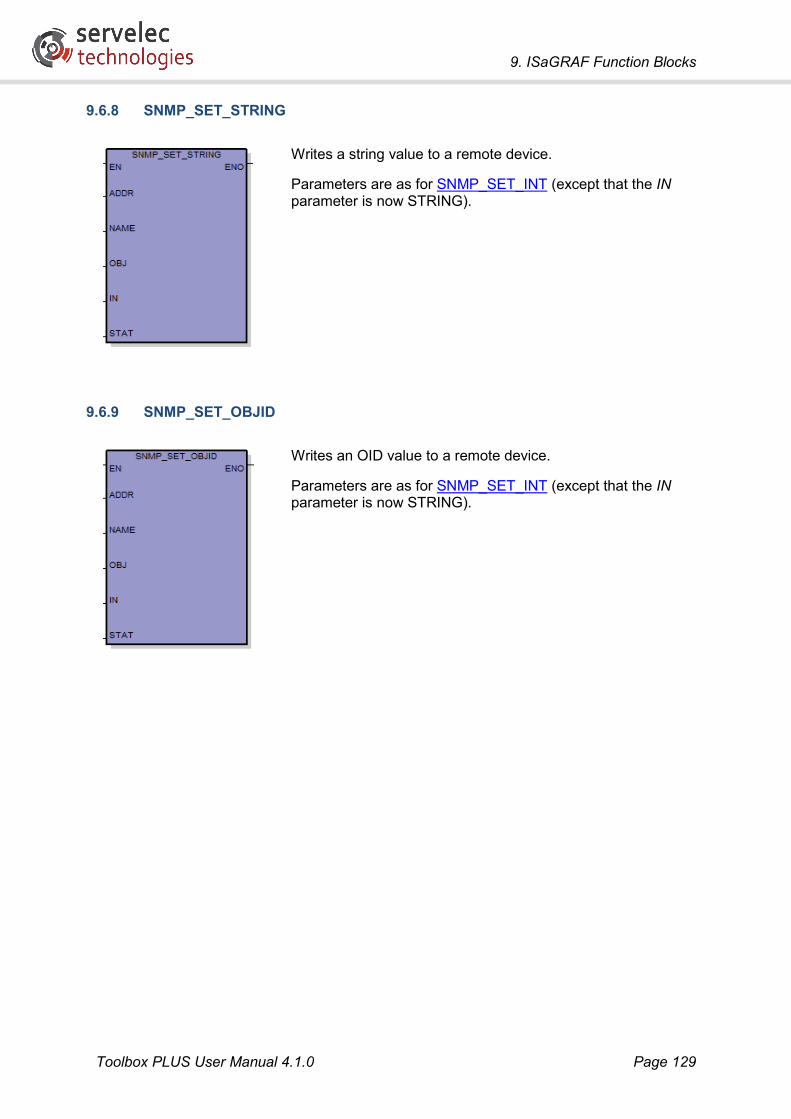
9. ISaGRAF Function Blocks
Toolbox PLUS User Manual 4.1.0 Page 129
9.6.8 SNMP_SET_STRING
Writes a string value to a remote device.
Parameters are as for SNMP_SET_INT (except that the IN parameter is now STRING).
9.6.9 SNMP_SET_OBJID
Writes an OID value to a remote device.
Parameters are as for SNMP_SET_INT (except that the IN parameter is now STRING).

9. ISaGRAF Function Blocks
Toolbox PLUS User Manual 4.1.0 Page 130
9.6.10 SNMP_SET_VALUE
Writes a value of any type to a remote device.
Parameter Type Description ADDR UINT Address of the RTU (1-65520) to which to write. NAME STRING(255) The community name to use in the request message. (See note under
SNMP_GET_INT) OBJ STRING(255) The object identifier in the remote device. TYPE DINT The ASN.1 type code for the object, e.g. 2 for integer, 66 for gauge
type. See ISaGRAF Constants for a list of defined words that may be used to specify the object type.
INT DINT For integer types (Boolean, Integer, Counter, Gauge, Time Ticks and Unsigned Integer), the value to write is specified here.
STR STRING(255) For OID objects, the value to write is specified as a dotted numeric string, e.g. ‘1.3.6.1.123’. For all other non-integer types, the data in the string will be written directly to the SNMP object.
STAT STRING(128) Name of a global DINT variable in which to store a status value: 0 if success, non-zero if error.

9. ISaGRAF Function Blocks
Toolbox PLUS User Manual 4.1.0 Page 131
9.7 SNMP Trap Protocol The following function blocks are used to send or receive SNMP Trap messages (asynchronous notifications).
9.7.1 SNMP_GET_TRAP
When a trap message is received, details associated with the message are stored in a queue. This function block returns details about the oldest trap message in the queue (if any).
Parameter Type Description ERR INT Status code. 0=message details successfully returned. Non-zero
indicates that there is no trap message in the queue, or other error condition.
COM STRING(128) The community string specified in the trap message. Note: there is no validation of the received community string.
IP STRING(16) The IP address of the agent that sent the trap message. OID STRING(255) The object identifier associated with the trap message. GTRP UINT The generic trap value of the trap message. The permissible values for
this parameter are defined in RFC 1157: A Simple Network Management Protocol (SNMP).
STRP UINT The specific trap value of the trap message. This value is device specific.
TIME UDINT Message timestamp (seconds since 1-Jan-1970)
If no trap messages have been received then an empty string is returned for COM, IP and OID, and 0 is returned for GTRP, STRP and TIME.

9. ISaGRAF Function Blocks
Toolbox PLUS User Manual 4.1.0 Page 132
9.7.2 SNMP_SEND_TRAP
Sends a trap message containing the value of a particular SNMP object to a remote device.
When generating this message, the IP address of the default Ethernet port of the CP-30 processor is used for the agent address and the current time is used for the time stamp parameter of the trap message.
Parameter Type Description ADDR DINT Address of the RTU (1-65520) to which to send trap message. COM STRING(128) The community name to use in the trap message. GTRP UINT The generic trap value to use in the trap message. The permissible
values for this parameter are defined in RFC 1157: A Simple Network Management Protocol (SNMP).
STRP UINT The specific trap value to use in the trap message. OID STRING(255) The object identifier to use in the trap message. VAL DINT Value of the object

9. ISaGRAF Function Blocks
Toolbox PLUS User Manual 4.1.0 Page 133
9.8 SNMP RMS Trap Protocol
9.8.1 SNMPRMS
Sends an SNMP Trap message to a remote device, emulating an RMS Systems RTU.
SNMP RMS messages differ from SNMP_SEND_TRAP messages in that information for multiple object identifiers defined in the RMS Systems MIB are sent within a single SNMP trap message. Object values can also be sent in the trap message.

9. ISaGRAF Function Blocks
Toolbox PLUS User Manual 4.1.0 Page 134
Parameter Type Description ADDR UINT Address of the RTU (1-65520) to which to send trap message. COM STRING(64) The community name to use in the trap message. SPEC DINT The specific RMS Systems message to send (101-111).
See Supported Message Types. PNAM STRING(20) The port name associated with the SNMP trap.
OID for this parameter is 1.3.6.1.4.1.4119.1.7.7.1 PCOD STRING(20) The position code of the port associated with the SNMP trap.
OID for this parameter is 1.3.6.1.4.1.4119.1.7.7.2 GCOD STRING(20) The group code of the port associated with the SNMP trap.
OID for this parameter is 1.3.6.1.4.1.4119.1.7.7.3 PNUM DINT The overall port number associated with the SNMP trap.
OID for this parameter is 1.3.6.1.4.1.4119.1.7.7.4 PTYP DINT The port type (1-4) associated with the SNMP trap: 1=digital, 2=analog,
3=temperature, 4=virtual. OID for this parameter is 1.3.6.1.4.1.4119.1.7.7.5
PTNM DINT The port type number of the port associated with the SNMP trap. This is the port number within the given port type rather than the overall port number within the configuration. OID for this parameter is 1.3.6.1.4.1.4119.1.7.7.6
ALRM DINT The number of alarms on the given port. OID for this parameter is 1.3.6.1.4.1.4119.1.7.7.7
ALMP DINT The alarm priority level of the port (1 = highest priority). OID for this parameter is 1.3.6.1.4.1.4119.1.7.7.8
ENUM DINT The external device number. OID for this parameter is 1.3.6.1.4.1.4119.1.7.7.9
ESTR STRING(20) The external device string. OID for this parameter is 1.3.6.1.4.1.4119.1.7.7.10
ERR BOOL Set TRUE if an error occurs.
Supported Message Types
The following message types are supported: SPEC Name Description
101 rtuAlarm Sent when a port goes into alarm
102 rtuARA Sent when a port goes into ARA
103 rtuHistoric Sent when a port goes into Historic
104 rtuNormal Sent when a port goes normal
105 rtuOutputActivated Sent when an output port is activated
106 rtuOutputDeactivated Sent when an output port is deactivated
107 rtuPowerFail Sent when power fails
108 rtuLogFull Sent when a log reaches the specified alarm threshold
109 rtuUnitConfigChange Sent when a unit setting has been changed
110 rtuPortConfigChange Sent when a port setting has been changed
111 rtuRuleFail Sent when the rules are enabled and they become invalid (either through a rule change or some other change in the RTU configuration)

9. ISaGRAF Function Blocks
Toolbox PLUS User Manual 4.1.0 Page 135
9.9 User Defined Protocol The following function blocks are used to send and receive arbitrary communications messages. These can be used to implement simple protocols.
9.9.1 USER_TX
Sends up to 255 bytes to a remote device.
Parameter Type Description ADDR UINT Address of the RTU (1-65520) to which to send the data. DATA STRING(255) Data bytes to send
9.9.2 USER_RX
Reads up to 255 bytes from an internal buffer containing data received from a remote device.
Parameter Type Description ADDR UINT Address of the RTU (1-65520) from which to read data. CNT UINT Maximum number of bytes to read (1-255) DATA STRING(255) Received data bytes. If no data have been received this will be an
empty string.

9. ISaGRAF Function Blocks
Toolbox PLUS User Manual 4.1.0 Page 136
9.9.3 USER_RX_BYTES
Returns the number of bytes that have been received from the remote device, but not yet read (using USER_RX).
Parameter Type Description ADDR UINT Address of the RTU (1-65520) to check for received data. CNT UINT Number of bytes available to read.
9.10 SMS Protocol
9.10.1 SEND_SMS
Sends an SMS message via a compatible 3G router to the specified phone number.
The message will be sent by connecting to the router’s Telnet interface and issuing a suitable command.

9. ISaGRAF Function Blocks
Toolbox PLUS User Manual 4.1.0 Page 137
Parameter Type Description ADDR UINT Destination RTU address (1-65520). A route must be set up to map this
address to the router’s actual IP address. TMPL STRING(255) A string specifying a template for the router’s “send SMS” command.
The string should contain %n (which will be replaced by the telephone number) and %t (which will be replaced by the message text). For example, if: TMPL = ‘send sms %n, %t’ NUMB = ‘+61400123456’ MSG = ‘A test’ then the following command string will be sent to the router: send sms +61400123456, A test followed by a carriage return. See ISaGRAF Constants for a list of defined words that may be used to specify pre-defined template strings for particular router types. Take note of the note below if you are using Ladder Logic.
USR STRING(255) The username to send when logging in to the router’s telnet interface. This is often the same username used to configure the router via its web browser interface.
PWD STRING(255) The password for the router’s telnet interface.. PORT UINT The TCP port number to use when connecting to the router’s telnet
interface (normally 23) NUMB STRING(255) The destination telephone number, in international format, e.g.
Australian mobile number 0400 123456 would be represented as ‘+61400123456’
MSG STRING(255) The message to send (max 160 characters) STAT STRING(255) The name of a global DINT variable in which a status value will be
placed. 0 indicates success, non-zero values indicate an error. Note: A zero status value indicates that the SMS command was issued to the router. This does not necessarily mean that the SMS message was successfully delivered to the mobile network.
Note: In the ISaGRAF Ladder Diagram editor, all string constants are converted to upper case. This means that if you specify a string constant (or ISaGRAF constant) for the TMPL, USR, PWD or MSG parameters, they will be changed to uppercase, which is generally not what you want, as router commands and login details are generally case sensitive.
To work around this, either:
• Assign the required values to string variables, either as initial values in the ISaGRAF dictionary editor or in Structured Text code, or
• Call the function block using Structured Text or Function Block Diagram, rather than using Ladder Logic.
See Sending an SMS for an example that calls the function block using Structured Text.

9. ISaGRAF Function Blocks
Toolbox PLUS User Manual 4.1.0 Page 138
9.10.2 PHONE_TO_STRING
Combines two integer values into a string which can then be used as the phone number input to the SEND_SMS function block.
A common use of this function is to enable SMS destination phone numbers to be updated from SCADA. DNP3 string variables are not currently supported, so this function block allows the destination telephone number to instead be set using two integer analog output points (DNPAOnnn).
Parameter Type Description PRE DINT Country/region prefix of the phone number. This can contain up to 9
digits and cannot have any leading ‘0’ digits. SUB DINT Subscriber number or the remaining digits of the phone number. This
can contain up to 9 digits and cannot have any leading ‘0’ digits. NUMB STRING(255) Contains the full phone number in the form of a string suitable for use
with the SEND_SMS function block. A leading ‘+’ character will be automatically added. For example, if: PRE = 614000 SUB = 12345 then the output string will be set as follows: NUMB = ‘+61400012345’
9.11 VRRP Protocol
9.11.1 VRRP
Returns the master/backup VRRP state for the local RTU.
Parameter Type Description MAST BOOL Set TRUE when the local RTU is operating as a master VRRP router.
Set FALSE when the local RTU is operating as a backup VRRP router. ERR BOOL Set TRUE if there is an error.

9. ISaGRAF Function Blocks
Toolbox PLUS User Manual 4.1.0 Page 139
9.12 General Communications These function blocks return information about the status of the various communications links managed by the RTU.
9.12.1 KF_GET_COMM_STATS
Returns communications statistics for the link between the local RTU and a particular remote RTU (or all RTUs).
See Interpreting communications statistics for more details on the meanings of the various statistics.
Parameter Type Description ADDR UINT Address of the RTU (1-65520) for which to return communications
statistics. Set to 0 to return statistics for all remote RTUs. ERR BOOL TRUE if an error occurred, or if no communications with the selected
RTU have been attempted. TXS UDINT Number of messages successfully transmitted to the selected RTU (or
all RTUs if ADDR=0). TXE UDINT Number of messages that were not able to be transmitted to the
selected RTU (or all RTUs if ADDR=0). RXS UDINT Number of messages successfully received from the selected RTU (or
all RTUs if ADDR=0). RXE UDINT Number of messages for which a valid response was not received from
the selected RTU (or all RTUs if ADDR=0)
Interpreting communications statistics
The meaning of the various statistics varies somewhat depending on the protocol and whether the RTU is operating as a slave or a master.
When the RTU is a slave:
• RXS is the number of valid messages received.
• RXE is not used. Invalid messages and messages not addressed to the RTU are ignored.
• TXS is the number of messages sent. For Modbus, this includes exception responses (e.g. where the requested data are not available).
• TXE is the number of reply messages that could not be sent, or DNP3 unsolicited messages where the RTU cannot connect to master.

9. ISaGRAF Function Blocks
Toolbox PLUS User Manual 4.1.0 Page 140
When the RTU is a master:
• TXS is the number of messages sent.
• TXE is the number of times where it was not possible to connect to the slave (Ethernet only). It also includes cases where there is no route defined for the slave address (except Modbus protocol).
• RXS is the number of valid messages received.
• RXE is the number of times an exception/error response was received, or where no response was received within the timeout period.
Furthermore:
• If a retry count is set then each attempt counts as a message.
• For DNP3, the message counts are really message fragment counts.
9.12.2 KF_RESET_COMM_STATS
Resets communications statistics for the link between the local RTU and a particular remote RTU (or all RTUs).
Parameter Type Description ADDR UINT Address of the RTU (1-65520) for which to reset communications
statistics. Set to 0 to reset statistics for all remote RTUs. ERR BOOL TRUE if an error occurred, or if no communications to the selected RTU
have been attempted.

9. ISaGRAF Function Blocks
Toolbox PLUS User Manual 4.1.0 Page 141
9.12.3 KF_GET_PORT_STATS
Returns communications statistics for a physical RTU port.
See Interpreting communications statistics for more details on the meanings of the various statistics.
Parameter Type Description PORT STRING(8) Port identifier. This is a string of the form ‘s:p’, where s is the slot
number (1-64, or 0 for the active CP-30) and p is the port number (1, 2, 3, 2.1, 2.2, 3.1 or 3.2).
ERR BOOL TRUE if an error occurred, or if no communications on the selected port have been attempted.
TXS UDINT Number of messages successfully transmitted on the selected port. TXE UDINT Number of messages that were not able to be transmitted on the
selected port. RXS UDINT Number of messages successfully received on the selected port. RXE UDINT Number of messages sent on the selected port for which a valid
response was not received.
For example, to retrieve statistics for the built-in Ethernet prot on the CP-30 you would set PORT=’0:1’. To specify port 3.2 (bottom port on an Option I2 card in option card slot 3) on an MC-31 in slot 22, use PORT=’22:3.2’.
9.12.4 KF_RESET_PORT_STATS
Resets communications statistics for the specified port
Parameter Type Description ADDR STRING(8) Port identifier. This is a string of the form ‘s:p’, where s is the slot
number (1-64, or 0 for the active CP-30) and p is the port number (1, 2, 3, 2.1, 2.2, 3.1 or 3.2).
ERR BOOL TRUE if an error occurred, or if no communications on the selected port have been attempted.

9. ISaGRAF Function Blocks
Toolbox PLUS User Manual 4.1.0 Page 142
9.12.5 KF_GET_PENDING
Indicates whether a message is pending (awaiting reply), either for a particular remote RTU, or a particular protocol, or globally.
This is typically used to prevent further messages being initiated until the previous one has completed or timed out.
Parameter Type Description ADDR UINT Address of the RTU (1-65520) to check for pending messages. Set to 0
to check for pending messages for all remote RTUs. PROT USINT Protocol to check for pending messages. Set to 0 to check for pending
messages for all protocols. See ISaGRAF Constants for a list of defined words that may be used to specify the protocol..
ERR BOOL TRUE if an error occurred. PEND BOOL TRUE if there is an outstanding message for which no reply has been
received, for the specified remote RTU address and/or protocol.

9. ISaGRAF Function Blocks
Toolbox PLUS User Manual 4.1.0 Page 143
9.12.6 KF_GET_ROUTE
Returns information about a communications route. A route specifies the port (and possible intermediate RTU) to use in order to send a message to a particular RTU address using a particular protocol.
Routes may be created in Toolbox PLUS, or may be added dynamically (e.g when a slave RTU is polled by a master), or may be modified in logic (using KF_SET_ROUTE).
Parameter Type Description DEV UINT Address of the RTU (1-65520) for which route information is to be
returned. PROT USINT Protocol for which route information is to be returned. See ISaGRAF
Constants for a list of defined words that may be used to specify the protocol..
ERR BOOL TRUE if an error occurred. TYPE DINT Returns type of route: 0=direct (messages can be sent directly to the
destination RTU), 1=indirect (messages must be sent via an intermediate RTU).
PORT STRING(8) For direct routes, returns the port to use to communicate with the destination RTU. This is a string of the form ‘s:p’, where s is the slot number (1-64, or 0 for the active CP-30) and p is the port number (1, 2, 3, 2.1, 2.2, 3.1 or 3.2).
ADDR STRING(16) For direct routes using an Ethernet port, returns IP address of destination RTU, e.g. ‘192.168.0.42’
VIA UINT For indirect routes, returns the address (1-65520) of the intermediate RTU through which messages are to be sent.

9. ISaGRAF Function Blocks
Toolbox PLUS User Manual 4.1.0 Page 144
9.12.7 KF_SET_ROUTE
Allows an existing communications route to be modified.
This can be used to change the port that is used to communicate with a particular RTU – for example, if a fault is detected.
Parameter Type Description DEV UINT Address of the RTU (1-65520) for which route information is to be
modified. PROT USINT Protocol for which route information is to be modified. See ISaGRAF
Constants for a list of defined words that may be used to specify the protocol..
TYPE DINT Sets type of route: 0=direct (messages can be sent directly to the destination RTU), 1=indirect (messages must be sent via an intermediate RTU). The defined words ROUTE_DIRECT and ROUTE_INDIRECT may also be used.
PORT STRING(8) For direct routes, sets the port to use to communicate with the destination RTU. This is a string of the form ‘s:p’, where s is the slot number (1-64, or 0 for the active CP-30) and p is the port number (1, 2, 3, 2.1, 2.2, 3.1 or 3.2).
ADDR STRING(16) For direct routes using an Ethernet port, sets IP address of destination RTU, e.g. ‘192.168.0.42’
VIA UINT For indirect routes, sets the address (1-65520) of the intermediate RTU through which messages are to be sent.
ERR BOOL TRUE if an error occurred.

9. ISaGRAF Function Blocks
Toolbox PLUS User Manual 4.1.0 Page 145
9.13 Event Logging The following function blocks are used to create and manage event logs on the local RTU, or a remote RTU.
9.13.1 KF_EVENT_LOG
Logs the current value of any global ISaGRAF variable, along with timestamp and other information.
Timestamps are logged accurate to one second, except for variables mapped to DI-10 or IOD-MX2/3/4 SOE inputs, which can be logged accurate to within a few milliseconds.
Class 1/2/3 DNP3 variables will be automatically logged whenever their value changes. However this function block can be used to create additional log entries by logging variables even when they haven’t changed (e.g. periodically).
Parameter Type Description REG STRING(16) Name of a global variable to log, e.g. ‘DNPAI3’ or ‘SL05IO3DI1’ or
‘MYVAR’. Note that for IOPOINT variables (DNP3 or I/O module points) it is not necessary to include the ‘.value’ suffix.
UTYP USINT For DNP3 variables, this is the event variation (1-7). For other variables, this is a user type code (0-31) which can optionally be used to filter events when uploading.
PRI USINT For DNP3 variables, this is the event class (1-3). For other variables, this is a user priority code (0-7) which can optionally be used to filter events when uploading.
DTYP USINT Not used (set to 0) ERR DINT 0 if OK, non-zero if an error occurred.
9.13.2 KF_CLEAR_EVENT_LOGS
Clears all event logs on the local or a remote RTU.
Parameter Type Description RTU UINT Address of remote RTU (1-65520) on which to clear event logs. Set to 0
to clear event logs on the local RTU. ERR DINT 0 if OK, non-zero if an error occurred.

9. ISaGRAF Function Blocks
Toolbox PLUS User Manual 4.1.0 Page 146
9.13.3 KF_GET_EVENT_LOG_COUNT
Returns the number of event logs currently stored on the local or a remote RTU.
Parameter Type Description RTU UINT Address of remote RTU (1-65520) from which to obtain event log count.
Set to 0 to return the number of event logs on the local RTU. DES STRING(16) Name of a global DINT variable in which to store the event log count. ERR DINT 0 if OK, non-zero if an error occurred.

9. ISaGRAF Function Blocks
Toolbox PLUS User Manual 4.1.0 Page 147
9.14 RTU System Data
9.14.1 KF_GET_ADDRESS
Returns the address of the local RTU.
Parameter Type Description RTU UINT Address of local RTU (1-65520)
9.14.2 KF_GET_FIRMWARE
Returns the local RTU firmware version.
Parameter Type Description NBR UDINT Firmware version number
9.14.3 KF_GET_RTU_TYPE
Identifies the type of processor module
Parameter Type Description TYPE USINT Processor type: 1=CP-30

9. ISaGRAF Function Blocks
Toolbox PLUS User Manual 4.1.0 Page 148
9.14.4 KF_GET_SYSTEMID
Returns the configured system ID byte (Kingfisher protocol message prefix) for the local RTU.
Parameter Type Description ID INT System ID byte (normally 174)
9.14.5 KF_GET_PROCESSOR
Identifies the backplane slot containing the active processor module.
Parameter Type Description SLOT UINT Active processor slot number (1-64)
9.14.6 KF_GET_MODULE_TYPE
Identifies the module type installed in the specified backplane slot.
Parameter Type Description SLOT UINT Slot number (1-64) TYPE UINT Detected module type (1-255):
1=AI-1/AI-4, 2=AO-2, 5=DI-1, 6=DI-5, 7=DO-1, 8=DO-2/DO-5/DO-6, 9=DI-10, 11=IO-2, 12=IO-3, 14=IO-4, 15=AO-3, 19=AI-10, 31=PS-1x/PS-2x, 48=MC-30, 50=IO-5, 60=CP-30, 88=MC-31, 255=No module installed

9. ISaGRAF Function Blocks
Toolbox PLUS User Manual 4.1.0 Page 149
9.14.7 KF_GET_MODULE_OK
Compares the module/card detected in a backplane slot with the module configured in the RTU’s configuration.
Parameter Type Description SLOT UINT Slot number (1-64) ERR BOOL Set TRUE if the specified slot number is invalid. STAT BOOL Module status. Set TRUE if a module is present in the specified slot, and
its type matches that specified in the RTU’s configuration.
9.14.8 KF_RESET_MODULE
Reset/reconfigure the module in the specified backplane slot.
For MC-30/MC-31 modules, a full reboot will be performed, after which the module will be re-detected and its configuration reloaded.
For I/O modules, the CP-30 internally marks the module as absent, after which the module will be re-detected and its configuration reloaded.
Parameter Type Description SLOT USINT Slot number (1-64) ERR BOOL Set TRUE if the specified slot number is invalid.
9.14.9 REBOOT
Reboots the local processor module.
Note: This function block has no input or output parameters, so it is not directly usable in Function Block Diagram (FBD) programs. You can, however, create a small Ladder Diagram function that calls REBOOT, then call that function from a FBD program.

9. ISaGRAF Function Blocks
Toolbox PLUS User Manual 4.1.0 Page 150
9.14.10 KF_GET_RTC
Returns the current RTU date/time, expressed as a single integer.
Parameter Type Description SEC DINT Current RTU time: seconds since 0:00 1-Jan-1970
9.14.11 KF_SET_RTC
Sets the current RTU date/time, expressed as a single integer.
Parameter Type Description SEC DINT New RTU time: seconds since 0:00 1-Jan-1970
9.14.12 KF_GET_TIME
Returns the current RTU date/time, expressed as separate time components
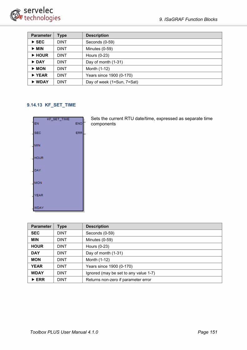
9. ISaGRAF Function Blocks
Toolbox PLUS User Manual 4.1.0 Page 151
Parameter Type Description SEC DINT Seconds (0-59) MIN DINT Minutes (0-59) HOUR DINT Hours (0-23) DAY DINT Day of month (1-31) MON DINT Month (1-12) YEAR DINT Years since 1900 (0-170) WDAY DINT Day of week (1=Sun, 7=Sat)
9.14.13 KF_SET_TIME
Sets the current RTU date/time, expressed as separate time components
Parameter Type Description SEC DINT Seconds (0-59) MIN DINT Minutes (0-59) HOUR DINT Hours (0-23) DAY DINT Day of month (1-31) MON DINT Month (1-12) YEAR DINT Years since 1900 (0-170) WDAY DINT Ignored (may be set to any value 1-7) ERR DINT Returns non-zero if parameter error

9. ISaGRAF Function Blocks
Toolbox PLUS User Manual 4.1.0 Page 152
9.14.14 GET_BP12V
Measures the voltage on the backplane 12V rail. Requires CP-30 hardware version 2 or later.
This is useful when using a Error! Unknown document property name. powered backplane. For a passive backplane the SLssPS11AI1 variable can also be used to read the equivalent data from the power supply module (see PS-1x or PS-2x).
Parameter Type Description V12 REAL 12V rail voltage in volts
9.14.15 GET_LOWBATT
Returns TRUE if the CP-30’s internal Lithium battery failed while the system was last powered off, which may have resulted in data loss (e.g. retained variables, data and time).
Once the battery has been replaced, this flag will be cleared after the next power cycle.
Parameter Type Description LOW BOOL TRUE if battery was low during last power off.
9.14.16 SET_BPFIELD
Enable or disable I/O module field power control (PCON signal). By default, field power is ON.
Requires CP-30 hardware version 2 or later. For hardware version 1, the field power is always ON.
Parameter Type Description ON BOOL Set TRUE to turn field power on, FALSE to turn it off.

9. ISaGRAF Function Blocks
Toolbox PLUS User Manual 4.1.0 Page 153
9.14.17 SET_BPAUX
Enable or disable AUX power output on a Error! Unknown document property name. powered backplane (CSR signal). By default, AUX power is ON.
Requires CP-30 hardware version 2 or later. For hardware version 1, the AUX power is always ON.
Parameter Type Description ON BOOL Set TRUE to turn AUX power on, FALSE to turn it off.

9. ISaGRAF Function Blocks
Toolbox PLUS User Manual 4.1.0 Page 154
9.15 Maths and Logic The following function blocks provide a few additional capabilities beyond those provided by the standard ISaGRAF library.
9.15.1 INCREMENT
Adds one to an integer variable.
Parameter Type Description INP DINT Input variable OUT DINT Output variable. May be the same as the input variable.
9.15.2 DECREMENT
Subtracts one from an integer variable.
Parameter Type Description INP DINT Input variable OUT DINT Output variable. May be the same as the input variable.
9.15.3 ChangeDetect
Detects change in an integer variable.
Parameter Type Description INP DINT Input variable OUT DINT Set to 1 if the input value has changed since the last time the function
block was executed, 0 otherwise

9. ISaGRAF Function Blocks
Toolbox PLUS User Manual 4.1.0 Page 155
9.15.4 MulDiv
Scales a floating point variable by multiplying it by an integer value then dividing by another value. The result is a floating point value.
Parameter Type Description INP REAL Input variable MUL DINT Multiplier DIV DINT Divisor OUT REAL Output variable. May be the same as the input variable.
9.15.5 MULDIV_INT
Scales an integer variable by multiplying it by a value then dividing by another value. The result is an integer.
Parameter Type Description INP DINT Input variable MUL DINT Multiplier DIV DINT Divisor OUT DINT Output variable. May be the same as the input variable.

9. ISaGRAF Function Blocks
Toolbox PLUS User Manual 4.1.0 Page 156
9.15.6 BCD_TO_BINARY
Converts a variable from Binary Coded Decimal to a normal integer value.
BCD uses each group of 4 bits to represent a decimal digit.
Parameter Type Description BCD DINT Input variable (16#000000-16#999999) BIN DINT Output variable (0-999999). May be the same as the input variable.
9.15.7 BINARY_TO_BCD
Converts an integer variable to Binary Coded Decimal.
BCD uses each group of 4 bits to represent a decimal digit.
Parameter Type Description BIN DINT Input variable (0-999999) BCD DINT Output variable (16#000000-16#999999). May be the same as the input
variable.
9.15.8 FPACK
Converts two 16-bit integer values to a floating point value.
Typically used when reading floating point values using the Modbus protocol, which splits floating point values across two 16-bit registers.
Parameter Type Description W1 UINT First integer variable (bits 15:0) W2 UINT Second integer variable (bits 31:16) FLT REAL Floating point output variable

9. ISaGRAF Function Blocks
Toolbox PLUS User Manual 4.1.0 Page 157
9.15.9 FUNPACK
Converts a floating point value into two 16-bit integers.
Typically used when writing floating point values using the Modbus protocol, which splits floating point values across two 16-bit registers.
Parameter Type Description FLT REAL Floating point variable W1 UINT First integer output variable (bits 15:0) W2 UINT Second integer output variable (bits 31:16)
9.15.10 F64PACK
Converts four 16-bit integer values to a long floating point value.
Typically used when reassembling a long floating point value read from Modbus. (The Modbus protocol splits 64-bit values across four 16-bit registers).
Parameter Type Description W1 UINT First integer variable (bits 15:0) W2 UINT Second integer variable (bits 31:16) W3 UINT Third integer variable (bits 47:32) W4 UINT Fourth integer variable (bits 63:48) F64 LREAL 64-bit floating point output variable

9. ISaGRAF Function Blocks
Toolbox PLUS User Manual 4.1.0 Page 158
9.15.11 F64UNPACK
Converts a floating point value into four 16-bit integers.
Typically used when transmitting a long integer value using Modbus. (The Modbus protocol splits 64-bit values across four 16-bit registers).
Parameter Type Description F64 LREAL 64-bit floating point variable W1 UINT First integer output variable (bits 15:0) W2 UINT Second integer output variable (bits 31:16) W3 UINT Third integer output variable (bits 47:32) W4 UINT Fourth integer output variable (bits 63:48)
9.15.12 U32PACK
Converts two 16-bit integer values into a 32-bit integer.
Typically used when reassembling a long integer value read from Modbus. (The Modbus protocol splits 32-bit values across two 16-bit registers).
Parameter Type Description W1 UINT First integer variable (bits 15:0) W2 UINT Second integer variable (bits 31:16) U32 UDINT 32-bit integer output variable

9. ISaGRAF Function Blocks
Toolbox PLUS User Manual 4.1.0 Page 159
9.15.13 U32UNPACK
Converts a 32-bit integer value into two 16-bit integers.
Typically used when transmitting a long integer value using Modbus. (The Modbus protocol splits 32-bit values across two 16-bit registers).
Parameter Type Description U32 UDINT 32-bit integer variable W1 UINT First integer output variable (bits 15:0) W2 UINT Second integer output variable (bits 31:16)
9.15.14 U64PACK
Converts four 16-bit integer values into a 64-bit integer.
Typically used when reassembling a long integer value read from Modbus. (The Modbus protocol splits 64-bit values across four 16-bit registers).
Parameter Type Description W1 UINT First integer variable (bits 15:0) W2 UINT Second integer variable (bits 31:16) W3 UINT Third integer variable (bits 47:32) W4 UINT Fourth integer variable (bits 63:48) U64 ULINT 64-bit integer output variable

9. ISaGRAF Function Blocks
Toolbox PLUS User Manual 4.1.0 Page 160
9.15.15 U64UNPACK
Converts a 64-bit integer value into four 16-bit integers.
Typically used when transmitting a long integer value using Modbus. (The Modbus protocol splits 64-bit values across four 16-bit registers).
Parameter Type Description U64 ULINT 64-bit integer variable W1 UINT First integer output variable (bits 15:0) W2 UINT Second integer output variable (bits 31:16) W3 UINT Third integer output variable (bits 47:32) W4 UINT Fourth integer output variable (bits 63:48)
9.15.16 NBIT
Set/clear a single bit in an integer variable.
Parameter Type Description IN UINT Input variable DATA BOOL TRUE=set bit, FALSE=clear bit BIT USINT Bit number to set/clear (1-16) OUT UINT Output variable. May be the same as the input variable.

9. ISaGRAF Function Blocks
Toolbox PLUS User Manual 4.1.0 Page 161
9.15.17 NCBT
Tests whether a single bit in an integer variable is closed (set).
Parameter Type Description IN UINT Input variable BIT USINT Bit number to test (1-16) OUT BOOL TRUE if bit is set (logic 1).
9.15.18 NOBT
Tests whether a single bit in an integer variable is open (clear).
Parameter Type Description IN UINT Input variable BIT USINT Bit number to test (1-16) OUT BOOL TRUE if bit is clear (logic 0).

9. ISaGRAF Function Blocks
Toolbox PLUS User Manual 4.1.0 Page 162
9.16 PID Controller The proportional-integral-derivative (PID) function block calculates the difference (or error value) between a measured process value and a desired setpoint and attempts to minimise this difference by adjusting the output variable. The PID calculation takes into account:
• A proportional component which calculates a response proportional to the current error value
• An integral component which calculates a response based upon accumulated error
• A derivative component which calculates a response based upon the rate of change of the error value.
9.16.1 KF_PID
Given a measured process value and a desired set-point, calculates the appropriate output value based on a Proportional-Integral-Derivative control formula.
The following formula is used by the PID function block:
Evaluated from 0 to t, where:
Kp = Proportional constant
Ki = Integral constant
Kd = Derivative constant
t = Sample interval
en = Process error for current sample
en-1 = Process error for previous sample, etc.

9. ISaGRAF Function Blocks
Toolbox PLUS User Manual 4.1.0 Page 163
Parameter Type Description PV REAL Measured process value SP REAL Desired set-point for the process value AM BOOL Automatic/manual mode.
If TRUE (automatic mode), the function block will calculate an output value based on proportional, integral and derivative components of the error value. If FALSE (manual mode), the function block output value will simply track the set-point value without calculation.
DIRE BOOL Direct/reverse mode. If TRUE (direct mode), the output value will increase as the measured process value increases. If FALSE (reverse mode), the output value will decrease as the measured process value increases.
KP REAL PID proportional constant. KI REAL PID integral constant.
This constant is set to zero when PV falls within the range of the anti-reset parameters, in order to prevent output value overshoot during initial tuning operations.
KD REAL PID derivative constant. TIME TIME Time interval (ms) between sampling the process variable.
Note that the minimum interval that can be used is defined by the ISaGRAF sample time.
DBDP REAL Dead-band positive The allowable positive error between PV and SP. If the positive error is less than this value, the output will not be adjusted. The dead-band settings can be used to suppress output hunting (oscillating output).
DBDN REAL Dead-band negative The allowable negative error between PV and SP. If the negative error is less than this value, the output will not be adjusted.
ANTP REAL Anti-reset positive The value of PV above which to suppress an integral response. The anti-reset range can be used suppress over-correction (and overshoot) of the output value during initial tuning actions where there is a significant difference between the PV and SP. Set to 0.0 to disable the anti-reset feature.
ANTN REAL Anti-reset negative The value of PV below which to suppress an integral response.
MIN REAL Minimum allowable output value. MAX REAL Maximum allowable output value. OUT REAL Output value.
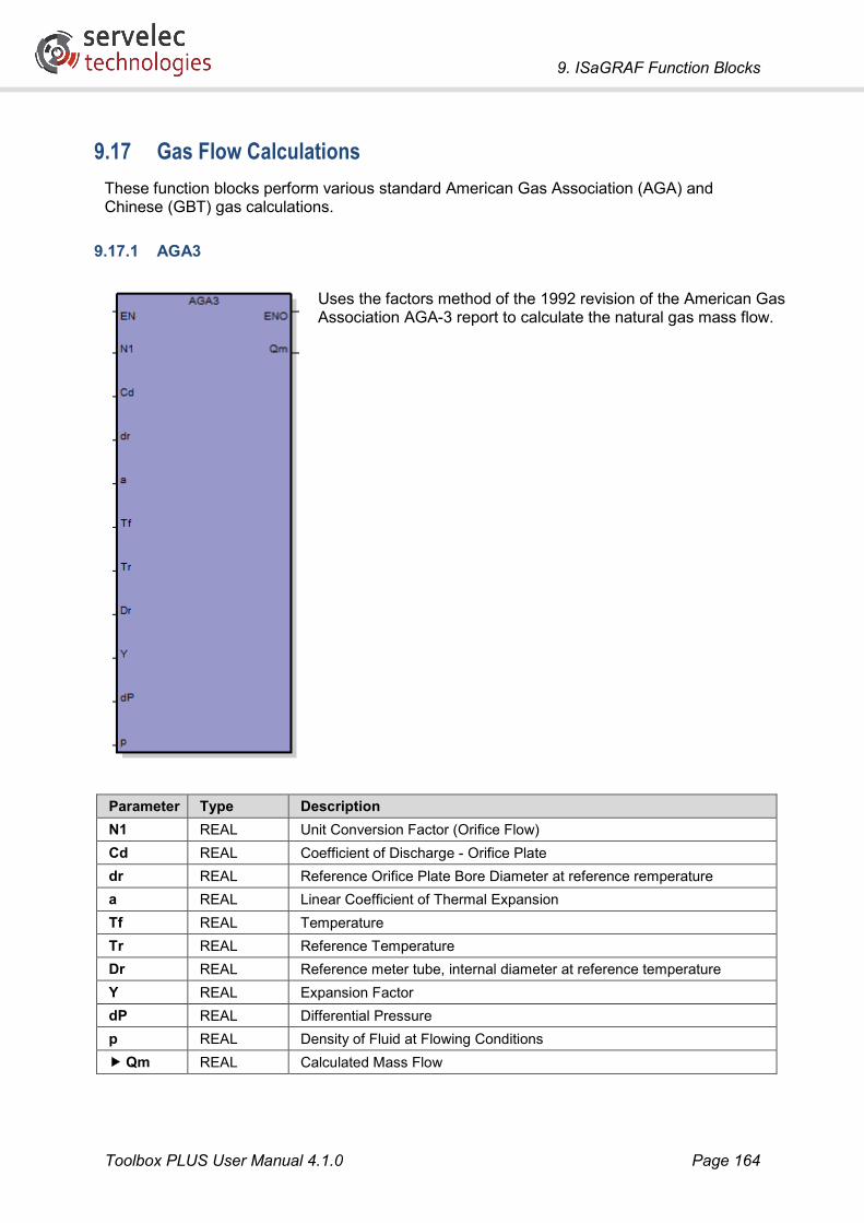
9. ISaGRAF Function Blocks
Toolbox PLUS User Manual 4.1.0 Page 164
9.17 Gas Flow Calculations These function blocks perform various standard American Gas Association (AGA) and Chinese (GBT) gas calculations.
9.17.1 AGA3
Uses the factors method of the 1992 revision of the American Gas Association AGA-3 report to calculate the natural gas mass flow.
Parameter Type Description N1 REAL Unit Conversion Factor (Orifice Flow) Cd REAL Coefficient of Discharge - Orifice Plate dr REAL Reference Orifice Plate Bore Diameter at reference remperature a REAL Linear Coefficient of Thermal Expansion Tf REAL Temperature Tr REAL Reference Temperature Dr REAL Reference meter tube, internal diameter at reference temperature Y REAL Expansion Factor dP REAL Differential Pressure p REAL Density of Fluid at Flowing Conditions Qm REAL Calculated Mass Flow

9. ISaGRAF Function Blocks
Toolbox PLUS User Manual 4.1.0 Page 165
9.17.2 AGA5
This calculation is used for gas energy metering applications and permits the calculation of Higher Heating Value (HHV, also known as the gross calorific value or gross energy) based upon volume flow consistent with AGA Report number 5 Natural Gas Energy Measurement.
This function accepts the volume percentage of gas constituents and returns the corresponding higher heating value in BTU.
Parameter Type Description SG REAL Specific gravity of the component gas under contract conditions. CO2 REAL Percentage volume of carbon dioxide N2 REAL Percentage volume of nitrogen O2 REAL Percentage volume of oxygen He REAL Percentage volume of helium CO REAL Percentage volume of carbon monoxide H2S REAL Percentage volume of hydrogen sulphide H2O REAL Percentage volume of water H2 REAL Percentage volume of hydrogen HHV REAL Calculated Higher heating value in BTU ERR BOOL Set TRUE if one or more parameters out of range

9. ISaGRAF Function Blocks
Toolbox PLUS User Manual 4.1.0 Page 166
9.17.3 AGA7
Uses the calculations from the 1980 revision of the American Gas Association AGA-7 report to calculate the volumetric flow of gas using the formula:
where
Qv = Flow Volume Qf = Flow Rate P = Measured Flow T = Measured Temperature Pgr = Reference Pressure Tgr = Reference Temperature Z = Gas Compressibility
Parameter Type Description Qf REAL Flow Rate at flowing conditions P REAL Pressure Pgr REAL Reference Pressure at specific gravity T REAL Temperature Tgr REAL Reference Temperature at specific gravity Z REAL Compressibility Factor (output from AGA8 Gross calculation) Qv REAL Calculated Volumetric Flow
Calculation Units
There are no required units for this calculation. Users must take care in ensuring that the units used are appropriate as recommended below.
• Pressure and Reference Pressure must be in the same units and they must be absolute units of pressure, such as psia, kPaa, MPaa or similar. Absolute units for the line pressure are typically the pressure from the transmitter (in gauge units) plus the local atmospheric pressure or the reading from an absolute pressure transmitter.
• Temperature and Reference Temperature must be in the same units and they must be the absolute units of Kelvin (deg C + 273.15) or Rankine (deg F + 459.67).
• The Compressibility correction factor is the ratio of the compressibility of the gas at base conditions to the compressibility of the gas at flowing conditions. To calculate this, you need to execute two AGA8 calculations, using the same gas composition, but the first with the base pressure and temperature to calculate the base compressibility (Zb) and the second with the flowing pressure and temperature to calculate the flowing compressibility (Zf). The Compressibility correction factor is then Zb / Zf. Either of the AGA8 Gross or AGA8 Detailed function blocks can be used, according to the available gas composition information available.
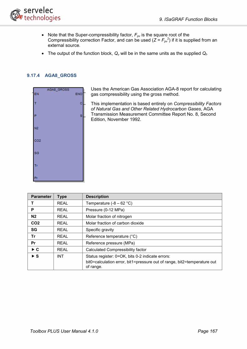
9. ISaGRAF Function Blocks
Toolbox PLUS User Manual 4.1.0 Page 167
• Note that the Super-compressibility factor, Fpv is the square root of the Compressibility correction Factor, and can be used (Z = Fpv
2) if it is supplied from an external source.
• The output of the function block, Qv will be in the same units as the supplied Qf.
9.17.4 AGA8_GROSS
Uses the American Gas Association AGA-8 report for calculating gas compressibility using the gross method.
This implementation is based entirely on Compressibility Factors of Natural Gas and Other Related Hydrocarbon Gases, AGA Transmission Measurement Committee Report No. 8, Second Edition, November 1992.
Parameter Type Description T REAL Temperature (-8 – 62 °C) P REAL Pressure (0-12 MPa) N2 REAL Molar fraction of nitrogen CO2 REAL Molar fraction of carbon dioxide SG REAL Specific gravity Tr REAL Reference temperature (°C) Pr REAL Reference pressure (MPa) C REAL Calculated Compressibility factor S INT Status register: 0=OK, bits 0-2 indicate errors:
bit0=calculation error, bit1=pressure out of range, bit2=temperature out of range.

9. ISaGRAF Function Blocks
Toolbox PLUS User Manual 4.1.0 Page 168
9.17.5 AGA8_DETAILED
Uses the American Gas Association AGA-8 report for calculating gas compressibility using the detailed characterisation method.
This implementation is based entirely on Compressibility Factors of Natural Gas and Other Related Hydrocarbon Gases, AGA Transmission Measurement Committee Report No. 8, Second Edition, November 1992.

9. ISaGRAF Function Blocks
Toolbox PLUS User Manual 4.1.0 Page 169
Parameter Type Description T REAL Temperature (-130 – 400 °C) P REAL Pressure (0-280 MPa) Meth REAL Molar fraction of methane Nitr REAL Molar fraction of nitrogen CaDi REAL Molar fraction of carbon dioxide Etha REAL Molar fraction of ethane Prop REAL Molar fraction of propane Watr REAL Molar fraction of water HySu REAL Molar fraction of hydrogen sulphide Hydr REAL Molar fraction of hydrogen CaMo REAL Molar fraction of carbon monoxide Oxy REAL Molar fraction of oxygen iBut REAL Molar fraction of i-butane nBut REAL Molar fraction of n-butane iPen REAL Molar fraction of i-pentane nPen REAL Molar fraction of n-pentane nHex REAL Molar fraction of n-hexane nHep REAL Molar fraction of n-heptane nOct REAL Molar fraction of n-octane nNon REAL Molar fraction of n-nonane nDec REAL Molar fraction of n-decane Heli REAL Molar fraction of helium Argn REAL Molar fraction of argon Cmpr REAL Calculated Compressibility ratio St INT Status register: 0=OK, bits 0-4 indicate errors:
bit0=calculation error (see below), bit1=pressure out of range, bit2=temperature out of range, bit4=gas components outside “normal” range.
The AGA8 Detail calculation is a fairly complicated non-linear calculation that includes a iteration loops (ie. it repeats a calculation many times until the result converges to a solution). The AGA8 function block limits these loops to a maximum of 100 iterations each, to limit the time taken to perform the calculation. A 'calculation error' indicates that after 100 iterations the result was still varying slightly, although a valid result will still be returned by the AGA8 calculation block.
The reason for the variation may be that the input parameters are close to the limits specified in the AGA8 Detailed specification. For further details about the parameter limits and the tolerance levels, please refer to the actual AGA8 Standard. If very precise accuracy is required from the result, the 'calculation error' bit can be used as a warning flag, otherwise it can be ignored.

9. ISaGRAF Function Blocks
Toolbox PLUS User Manual 4.1.0 Page 170
9.17.6 AGA11
Calculates the volumetric flow of gas consistent with AGA Report number 11, Measurement of Natural Gas by Coriolis Meter.
Volumetric flow (QB) is calculated based on mass flow rate (QM) returned from a Coriolis meter and the gas density (PB).
The gas density is calculated from the molar mass (Mr) of the gas using the same gas constituent information employed in calculation of the AGA 8 detailed gas compressibility using the formula:

9. ISaGRAF Function Blocks
Toolbox PLUS User Manual 4.1.0 Page 171
Parameter Type Description PB REAL Gas pressure under contract conditions TB REAL Gas temperature under contract conditions QM REAL Mass flow rate from Coriolis meter Z REAL Gas compressibility under contract conditions
This value should be derived from the AGA8_DETAILED function block, using the same molar fractional gas constituents.
METH REAL Molar fraction of methane N2 REAL Molar fraction of nitrogen CO2 REAL Molar fraction of carbon dioxide ETH REAL Molar fraction of ethane PROP REAL Molar fraction of propane H20 REAL Molar fraction of water H2S REAL Molar fraction of hydrogen sulphide H2 REAL Molar fraction of hydrogen CO REAL Molar fraction of carbon monoxide O2 REAL Molar fraction of oxygen IBUT REAL Molar fraction of i-butane NBUT REAL Molar fraction of n-butane IPEN REAL Molar fraction of i-pentane NPEN REAL Molar fraction of n-pentatne HEXA REAL Molar fraction of n-hexane HEPT REAL Molar fraction of n-heptane NOCT REAL Molar fraction of n-octane NONA REAL Molar fraction of n-nonane DECA REAL Molar fraction of n-decane HE REAL Molar fraction of helium AR REAL Molar fraction of argon QB REAL Calculated volumetric flow D REAL Calculated mass density ERR BOOL TRUE if one or more parameters out of range

9. ISaGRAF Function Blocks
Toolbox PLUS User Manual 4.1.0 Page 172
9.17.7 GBT17747_2
This function calculates gas compressibility and heating capacity using Chinese gas metering standard GB/T 17747-2.

9. ISaGRAF Function Blocks
Toolbox PLUS User Manual 4.1.0 Page 173
Parameter Type Description P REAL Gas pressure under flowing conditions (MPa) TEMP REAL Gas temperature under flowing conditions (°C) C1 REAL Molar fraction of ethane C2 REAL Molar fraction of propane C3 REAL Molar fraction of methane IC4 REAL Molar fraction of i-butane NC4 REAL Molar fraction of n-butane IC5 REAL Molar fraction of i-pentane NC5 REAL Molar fraction of n-pentatne C6 REAL Molar fraction of n-hexane C7 REAL Molar fraction of n-heptane C8 REAL Molar fraction of n-octane C9 REAL Molar fraction of n-nonane C10 REAL Molar fraction of n-decane H2O REAL Molar fraction of water O2 REAL Molar fraction of oxygen H2S REAL Molar fraction of hydrogen sulphide CO2 REAL Molar fraction of carbon dioxide CO REAL Molar fraction of carbon monoxide N2 REAL Molar fraction of nitrogen H2 REAL Molar fraction of hydrogen HE REAL Molar fraction of helium AR REAL Molar fraction of argon Z REAL Calculated standard compressibility under flow conditions ZN REAL Calculated supercompressibility under reference conditions FPV REAL Calculated supercompressibility under flow conditions GR REAL Calculated relative density HVS REAL Calculated volume heating capacity HMS REAL Calculated mass heating capacity

9. ISaGRAF Function Blocks
Toolbox PLUS User Manual 4.1.0 Page 174
9.17.8 GBT21446
This function blocks calculates natural gas volume flow rate based on standard orifice metering. This calculation is described in the Chinese standard GB/T 21446.
Parameter Type Description DP REAL The differential pressure returned from the orifice meter (Pa) P REAL Absolute static gas pressure under flowing conditions (MPa) TEMP REAL Temperature under flowing conditions (°C) ODIA REAL Orifice plate bore diameter (m) OMTE REAL Orifice plate thermal expansion coefficient OSER REAL Service time MDIA REAL Meter tube internal diameter (m) MMTE REAL Meter tube thermal expansion coefficient MROU REAL Absolute roughness GR REAL Specific gravity FPV REAL Super compressibility under flow conditions TAP REAL Mode of pressure tap QVMS REAL Calculated volume flow rate QMNS REAL Calculated mass flow rate

9. ISaGRAF Function Blocks
Toolbox PLUS User Manual 4.1.0 Page 175
9.18 Obsolete Function Blocks The following function blocks currently appear in the ISaGRAF selection list, but are obsolete or not supported. These function blocks should not be used.
9.18.1 AGA1
This function block is not supported.
9.18.2 AGA9
The AGA9 report concerns the measurement of the flow of natural gas using an Ultrasonic meter. This report refers the reader to the calculations in the AGA7 report, hence the AGA7 function block should be used for these applications.
9.18.3 DNPM_ANALOG_COMMAND
This has been superseded by the DNPM_ANALOG_16BIT_COMMAND, DNPM_ANALOG_32BIT_COMMAND and DNPM_ANALOG_FLOAT_COMMAND function blocks.
9.18.4 IMAGE
This function block is not supported.
9.18.5 TRIO
This function block is not supported.
9.18.6 KF_CLEAR_PENDING
This function block is not supported.

10. ISaGRAF - Logic Examples
Toolbox PLUS User Manual 4.1.0 Page 176
10. ISaGRAF - Logic Examples A Toolbox PLUS project containing all the Ladder Diagram logic examples below is available from the Servelec Technologies website.
10.1 Detecting Modules The logic below uses the KF_GET_MODULE_OK function block to confirm that the modules detected in slots 1, 2 and 3 match the configuration loaded in the RTU.
10.2 Scaling The logic below uses the MULDIV_INT function block to convert an analog input (SL03IO3AI1.value) into engineering units. The input has a raw range of 0-32760. The input is divided by 32760 and then multiplied by 10000 to convert it to a range of 0-10000. This value can then be displayed as 0-1000.0 or 0-100.00 L/s in SCADA software. FlowLperSec is a DINT variable.

10. ISaGRAF - Logic Examples
Toolbox PLUS User Manual 4.1.0 Page 177
10.3 Hours ON Every 3600 milliseconds (3.6 seconds or 1/1000th of an hour) the logic below checks if SL03IO3DI1.value is ON and if it is, HrsRun (a DINT variable) is incremented. HrsRun then contains the number of 0.001 hour intervals that the input is ON i.e. 0 to 999,999 = 0 to 999.999 Hrs.
10.4 Counting Pulses I/O inputs are sampled once per ISaGRAF logic cycle (nominal rate 100ms). This means that low speed pulses (up to 5 pulses per second) can be counted using logic.
The actual pulse rate that the RTU can count depends on how fast the logic and I/O are processed. The nominal cycle time can be longer than 100ms if there is a large amount of logic or communications to process.
To count higher pulse rates (up to 10 kHz), a DI-10 or DI-5 digital input module can be used. These modules have dedicated hardware counters and do not rely on the logic cycle time to count pulses.
The logic below shows how to count pulses using a positive (rising) edge trigger contact (“P’ indicator in the contact symbol). Every time there is a new pulse, PulsesToday (a DINT variable) is incremented.
10.5 Flow Totalisation The following example shows how to accumulate a flow volume from a flow-rate analog input (SL03IO3AI1.value). For this example, the flow-rate engineering units are 4-20mA=0-1000 L/s. Each second, the number of litres that have flowed (FlowLastSec [a DINT variable]) is calculated by dividing the analog input by 32760 (the raw analog input range) and then

10. ISaGRAF - Logic Examples
Toolbox PLUS User Manual 4.1.0 Page 178
multiplying by 1000 (the high limit of the engineering units). This number of litres is then added to the FlowToday total (a DINT variable).
10.6 Daily Totals Daily totals are created by rolling over current totals at midnight. The current totals are copied to yesterday totals and then the current totals are reset.
In the example below, CurrentDAY and SavedDAY are DINT variables and Rollover is a BOOL variable. The KF_GET_TIME function block is used to check the current time. When the value for CurrentDAY changes at midnight, SavedDAY is updated and Rollover is set TRUE for one logic scan.
When Rollover is TRUE, the PulsesToday total is copied to PulsesYesterday and then zero is copied to PulsesToday.

10. ISaGRAF - Logic Examples
Toolbox PLUS User Manual 4.1.0 Page 179
10.7 Exception Reporting Digitals An exception report can be generated when a single digital bit changes state or when any of the bits in a variable change state.
Note that if the DNP3 protocol is used then no logic is required – simply map DNP variables onto the required I/O points and enable unsolicited reporting. This section describes how to achieve this using Kingfisher protocol.
10.7.1 Monitoring A Single Bit
In the example below, a single digital input variable from an IO-3 module (SL03103DI1.value) is monitored for change. If the input changes, an exception report flag is set (ExReport).
10.7.2 Monitoring Multiple Bits
In the example below, the four digital inputs from an IO-3 module (SL03IO3DI{1-4}.value) are copied to Kingfisher register 1 (KFR1). If this variable changes (ie. if any bit changes), then NewValue (DINT) will be set to 1, causing an exception report flag is set.

10. ISaGRAF - Logic Examples
Toolbox PLUS User Manual 4.1.0 Page 180
10.7.3 Sending The Exception Report
The logic below first uses KF_GET_PENDING to determine whether there are any outstanding Kingfisher protocol messages. If not, and an exception report needs to be sent, then KF_TX_DATA is used to transmit the list of registers specified by LocalRegisters to RTU 7. The ExReport flag is then cleared.
In this case the LocalRegisters array need only contain one element, and that element should be the value 1 (to indicate that register KFR1 should be sent).
10.8 Exception Reporting Analog Variables The example below shows how to trigger an exception report when an analog input (SL03IO3AI1.value) changes by 5% (of the full analog range) from the last reported value. This is done by using two DINT variables (AI1HiLimit, AI1LoLimit) and a constant. The variables are used to store the last reported value plus the constant and the last reported value minus the constant. When the analog value moves above or below these values, an exception report is triggered and the thresholds are updated (as illustrated below).
The constant to use is calculated as percentage of the analog or register range. For analog inputs which have a range of 0-32760 (32767 for an AI-10), a 1% change is represented in

10. ISaGRAF - Logic Examples
Toolbox PLUS User Manual 4.1.0 Page 181
the RTU by a change of about 328 (0.01 x 32760). Similarly, a 5% change is represented in the RTU by a change of 1638 (0.05 x 32760).
To send the new analog value (that was copied to KFR2 in the logic above) to another RTU, use the same method as for Sending The Exception Report above.
10.9 Event Logging The RTU is able to keep a record of variables and their values over time. Kingfisher or DNP3 variables can be logged on change or periodically. The maximum number of event logs that an RTU will keep is configured in the RTU Properties, General tab. By default, the RTU will keep up to 10,000 event logs.
10.9.1 Logging Kingfisher Variables
The example below uses KF_EVENT_LOG to create an event log whenever digital input 1 (SL03IO3DI1.value) changes state.

10. ISaGRAF - Logic Examples
Toolbox PLUS User Manual 4.1.0 Page 182
10.9.2 Logging DNP Variables
The example below creates periodic event logs (every 60 seconds) for DNP Analog Input DNPAI0, with a priority of 2 (class 2 data), using event variation 1.

10. ISaGRAF - Logic Examples
Toolbox PLUS User Manual 4.1.0 Page 183
10.10 Logic Examples – Polling Polling is usually performed by the master RTU in order to get a regular update of remote RTU data and to determine if communications to the remote RTUs have failed.
10.10.1 Basic Polling
The logic below polls RTU7 Local Register Variables 1, 2 and 100 every 60 seconds. If the poll is successful then registers KF7R1, KF7R2 and KF7R100 on the local RTU will be updated.
RTU7Registers is an INT_ARRAY variable containing three elements: 1, 2, 100.
10.10.2 Polling After Data Has Expired
If a remote RTU has exception reported to the master RTU recently, it is not necessary to poll the remote RTU until the data is older than X minutes (where X is ideally a SCADA set-point with a default value of say 10 minutes). If exception reports are generated frequently, it may never be necessary to poll the remote RTU. This minimises the required communications volume.
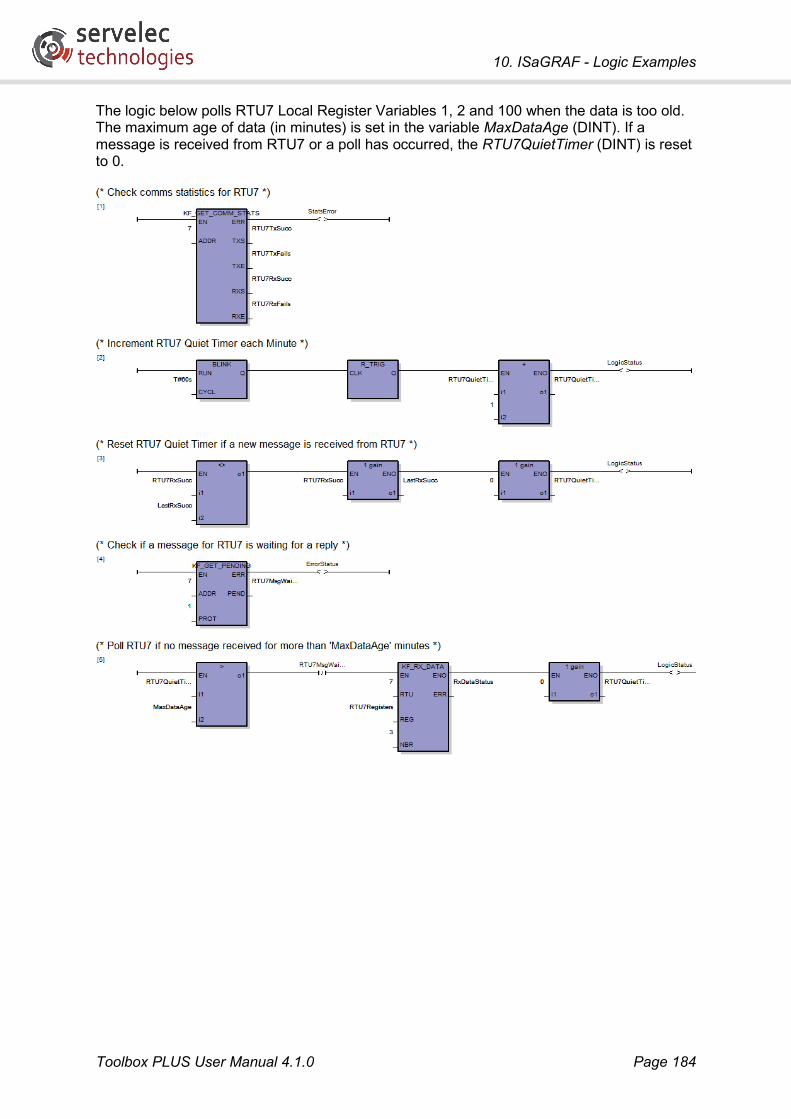
10. ISaGRAF - Logic Examples
Toolbox PLUS User Manual 4.1.0 Page 184
The logic below polls RTU7 Local Register Variables 1, 2 and 100 when the data is too old. The maximum age of data (in minutes) is set in the variable MaxDataAge (DINT). If a message is received from RTU7 or a poll has occurred, the RTU7QuietTimer (DINT) is reset to 0.
10. ISaGRAF - Logic Examples
Toolbox PLUS User Manual 4.1.0 Page 185
10.11 Modbus Protocol Kingfisher RTUs can be configured to behave as a Modbus master or slave. The following examples outline both configurations.
10.11.1 Setting up an RTU to be a Modbus Slave
In this example the RTU is being polled by an Operator’s Panel using Modbus/RTU over a serial link. This would be configured as follows:
• Add the Modbus RTU protocol to the RTU (RTU Properties - Protocols).
• Add serial port 2 to the RTU configuration (RTU Properties - Ports)
• Edit serial port 2. From the Settings tab of port 2, set Bits per second to suit the device and enable the Modbus RTU protocol.
• Create local Modbus variables to be polled by the Modbus Master device (Adding Variables). Example: MODH71 - Modbus Holding register 71. See Modbus Variables for Modbus variable formats and addressing details.
• Add an ISaGRAF logic program to copy data into the Modbus variables as required. Alternatively, I/O channels can be directly mapped to Modbus variables (Editing Variables)
• Download the Configuration and Logic to the RTU.
Note that Modbus addresses are 8 bit, so if the RTU’s address is greater than 255 then only the lower 8 bits should be specified when configuring the master device. See Modbus Extended Addresses for more details.
10.11.2 Setting up an RTU to be a Modbus Master
In this example the RTU is polling a remote slave RTU (address 7) using Modbus/RTU over a serial link. This would be configured as follows:
• Add the Modbus RTU protocol to the RTU.
• Add serial port 2 to the RTU configuration
• Edit serial port 2. From the Settings tab of port 2, set Bits per second to suit the remote RTU and enable the Modbus RTU protocol.
• Add a route (direct, using serial port 2) for address 7 to the RTU’s route list (RTU Properties – Routes).
• Create Modbus Variables to store the data polled from the Modbus Slave device (Adding Variables). Example: MOD7H1001 to MOD7H1002 (Modbus device 7, Holding Registers 1001 to 1002). Note: Local Registers (#Rx) polled from a PC-1, LP-x or CP-11/21 RTU start at 1001. Therefore to poll #R10, Modbus holding register 1010 would be polled.
• Create local Modbus variables that correspond to the registers to be written to the Modbus Slave device. Example: MODH1010 (Modbus Holding register 1010). To read or write floating point values using the Modbus protocol, please see the FPACK and FUNPACK function blocks.

10. ISaGRAF - Logic Examples
Toolbox PLUS User Manual 4.1.0 Page 186
• Configure a MODBUS function block in an ISaGRAF logic program, using the appropriate variables or constants for the inputs and output. An example is shown below.
• Download the Configuration and Logic to the RTU.
The logic below polls Modbus holding registers 1001 and 1002 from RTU7 using the Modbus protocol every 10 seconds. The data are stored in MOD7H1001 and MOD7H1002. Modbus function code 3 (Read Holding Registers) is used.
Also, when the SetData variable is set the local holding register MODH1 will be written to holding register 1010 on the slave device. Modbus function code 6 (Write Holding Register) is used; if more than one register needs to be written then function code 16 (Write Multiple Holding Registers) can be used.

10. ISaGRAF - Logic Examples
Toolbox PLUS User Manual 4.1.0 Page 187
10. ISaGRAF - Logic Examples
Toolbox PLUS User Manual 4.1.0 Page 188
10.12 Allen Bradley Protocol
10.12.1 Communicating With an Allen Bradley SLC500 PLC
To configure the RTU to poll an Allen Bradley PLC:
• Add the Allen Bradley DF1 protocol to the RTU (RTU Properties - Protocols).
• Add a serial port to the RTU configuration (RTU Properties - Ports)
• Edit the serial port. From the Settings tab of port 2, set Bits per second to suit the remote device and enable the Allen Bradley DF1 protocol.
• Add a route (direct, using the desired serial) for the PLC’s station address to the RTU’s route list (RTU Properties – Routes).
• Create one or more Kingfisher Local Register variables to send to the PLC or to store data from the PLC.
• Configure ABDF1_RX and/or ABDF1_TX function blocks in an ISaGRAF logic program.
• Download the Configuration and Logic to the RTU.
The logic below polls 50 registers starting at N10:1 from an Allen Bradley PLC (station address 26) every 10 seconds and stores the data in KFR10 to KFR60.

10. ISaGRAF - Logic Examples
Toolbox PLUS User Manual 4.1.0 Page 189
Note 1: The simplest way to connect between an RTU serial port and an Allen Bradley PLC is to use an RS232 null modem cable (can use the ADP-05 adaptor and an RJ45 to RJ45 patch lead). An Allen Bradley SLC5/03 CPU has a DB9 male port while the SLC5/02 CPU has an RS485 RJ45 port and may need to have a communications module installed for RS232 (RS485 can be used instead).
Note 2: If a 1785-KE interface module is used between the PLC and the RTU, the 1785-KE station number must also be configured in the Route list. The PLC should then be configured as an indirect link via the 1785-KE station address.
10.13 Sending an SMS
10.13.1 Configuration
The first task is to set up the 3G router and configure the RTU:
• Configure the router as per its user manual. This will generally involve connecting to the router’s web-based configuration interface using a web browser. Make a note of the following router settings:
• Router IP address
• Telnet port number (normally 23)

10. ISaGRAF - Logic Examples
Toolbox PLUS User Manual 4.1.0 Page 190
• Username and password for Telnet interface (often the same as for the web configuration interface)
• If the router model is not one of the ones for which a command template string has been defined (see ISaGRAF Constants) then you will need to determine the format of the command used to send an SMS and use it to devise a suitable template.
• Connect the router to the LAN such that its IP address is accessible to the RTU.
• In Toolbox PLUS, enable the SMS protocol on the required Ethernet port.
• In Toolbox PLUS, select an “RTU address” for the router (1-65520) and create a route to this address, specifying the router’s IP address. Make sure that the SMS Protocol checkbox is ticked for this route.
• In ISaGRAF, create appropriate logic to trigger the SEND_SMS function block. See below for more details.
• Save the configuration and download to the RTU.
10.13.2 Logic
In the following Structured Text program the logic checks a variable waterLevelAlarm, which is assumed to have been set true if an alarm condition exists. If this variable is set, and we are not currently sending an SMS, a suitable message is constructed in the string variable smsTxt, then the SEND_SMS function block is called. This should result in a text message similar to the following being sent to the phone number specified in the phoneNumber string variable:
Site 10 Water Tank Low: 29 ML
As written, the logic will repeatedly send text messages while the waterLevelAlarm variable remains true. In a real system additional logic would typically be included to limit the number of messages sent.

10. ISaGRAF - Logic Examples
Toolbox PLUS User Manual 4.1.0 Page 191
In this example the router’s RTU address is arbitrarily chosen to be 99, so in the RTU configuration a route would need to be defined linking this address to the router’s IP address.
In Structured Text, it is necessary to create an instance of each function block, and then call that instance. In this case the pendingFB variable is an instance of the KF_GET_PENDING function block, and send_smsFB is an instance of SEND_SMS. In the case of KF_GET_PENDING, the function block output is tested using pendingFB.Pending – “Pending” is the full name of the PEND output (full names are visible on the ISaGRAF dictionary page).
Use the ISaGRAF dictionary page to create function block instances. The name of the function block should be specified in the Type column. The following shows the variables and function block instances used in this program:

11. Redundancy
Toolbox PLUS User Manual 4.1.0 Page 192
11. Redundancy Redundancy allows RTUs installed in critical applications to continue operating normally when a power supply, a processor or a communications link fails. Each RTU can also be monitored and controlled by two or more PCs running SCADA software as detailed in the topic Redundant PCs.
11.1 Redundant Processors
11.1.1 Overview
To configure a redundant processor, simply add a second CP-30 module to the RTU. The second CP-30 will act as a backup and will automatically take over in the event that the primary processor fails.
One CP-30 processor must be installed in an even-numbered slot of the RTU backplane and one processor must be installed in an odd-numbered slot of the backplane. The processor installed in the even-numbered slot is called the primary processor, while the processor installed in the odd-numbered slot is the secondary processor.
Initially, the primary processor operates in active mode: it scans the I/O, runs the logic, and initiates and responds to communication messages. The secondary processor remains in standby mode ready to switch to active mode if the primary processor fails. The standby processor ports still respond to communications messages, but it does not run its logic or initiate messages, and will reject any write requests.
To keep the standby processor up to date, logic information, event logs and communication indices are regularly updated in the standby processor while the active processor is running.
The F3 LED indicates active or standby mode of each processor:
• When steady on, the processor is in active mode. All data have been synchronised to the standby processor.
• When flashing (0.5 Hz), the processor is in standby mode.
• If the LED is off then the processor is in active mode, but not all data (symbol values, event logs) have been synchronised to the standby processor. When the standby processor is first detected by the active, it is normal for the F3 LED to switch off for a period of time, which could be up to a few minutes if a large number of events have been logged. It may also switch off momentarily during normal operation if there is a burst of events. Note that if the active processor fails before synchronisation is complete (i.e. while the F3 LED is off) then the standby will still take over control, but some logged events may be lost.
The processor modules do not need to be installed physically next to each other. They just need to be in odd and even-numbered slots somewhere on the RTU backplane.
11.1.2 Active and Standby Processor Operation
In a single processor system, the CP-30 is responsible for scanning input modules, processing logic, updating output modules and initiating and responding to communications

11. Redundancy
Toolbox PLUS User Manual 4.1.0 Page 193
messages. In a redundant processor system, the active processor still does all this, but also regularly updates the standby processor with the following items:
• ISaGRAF symbols (dictionary variables) that were modified during the last cycle of logic execution. This includes function block parameters.
• New Kingfisher and DNP3 event logs. The values, flags and time stamps as recorded in the active processor module are all copied.
• DNP3 event list indices
• Time is synchronised every second. Note: protocols are only enabled on the standby processor after receiving the first time synchronisation from the active processor. This ensures that I/O points have been read from the hardware modules before the protocol is enabled.
Note: Variables (e.g. arrays) which are larger than 1000 bytes will not be synchronised. You should structure your logic such that no variable or array is larger than this size. See ISaGRAF Variable Types for information on the sizes of various data types. For example, an IOPOINT_D variable is 16 bytes long, so in order to be synchronised, an array of these variables should contain no more than 62 elements.
Note: Event logs recorded before the last power cycle are not copied to the standby processor. If all the event logs are cleared in the active processor during operation (e.g. using logic), then the event logs in the standby processor will also be cleared.
The standby processor’s responsibilities include:
• Receiving the above data from the active processor and updating its local copy of variable values and event logs.
• Responding to incoming communications read requests. Requests to write data to the RTU will be rejected, as will requests to read DNP3 events. DNP3 static values (class 0 data) will be returned.
• Monitoring backplane activity. If no activity is seen for 500ms then it is concluded that the primary processor has failed. The standby processor will then become the active processor.
When a CP-30 starts up, it first monitors backplane activity for a period of time. It will only decide to become the active processor if no activity is detected. This initial timeout is 500ms for the primary (even slot) processor, and 10,000ms for the secondary. This asymmetric setting ensures that when both are powered up simultaneously, it will be the primary processor that initially becomes active.
Note that apart from this bias on initial startup, the primary and secondary processors are otherwise treated equally. For example, if the primary CP-30 is removed (causing the secondary to become active) and then replaced, the secondary will continue to operate as the active processor. The primary will only become active in the event that the secondary fails.
11.1.3 Configuring Redundant Processors
Ensure one processor is installed in an even slot on the backplane and the other processor is installed in an odd slot.
In Toolbox PLUS, after creating a new CP-30 RTU configuration, add a second CP-30 module to the RTU. Toolbox PLUS will automatically label the processors “Primary” and “Secondary”.

11. Redundancy
Toolbox PLUS User Manual 4.1.0 Page 194
In a redundant processor configuration, you can either:
• Use an identical configuration for both the primary and the secondary CP-30s, which is referred to as “mirrored mode”, or
• Use independent configurations for the primary and secondary CP-30s.
By default, a single mirrored configuration will be created. This can then be downloaded to the primary and secondary processors in turn.
A mirrored configuration is simpler to manage, however sometimes independent primary and secondary configurations will be required. For example, if the two CP-30s need to be accessible via Ethernet (which is a common requirement), then they will need independent IP addresses and therefore separate (non-mirrored) configurations.
To create independent primary and secondary configurations, it is necessary to switch off mirrored mode, by clicking the Mirror toolbar button.
Mirror mode on – same configuration for primary and secondary processors.
Mirror mode off – independent configurations for primary and secondary processors.
With mirror mode switched off, Toolbox PLUS will maintain two separate configurations. At any one time, you will be editing either the Primary or the Secondary configuration. The configuration being edited is indicated by:

11. Redundancy
Toolbox PLUS User Manual 4.1.0 Page 195
• One of the CP-30 modules being highlighted in the module list, and
• “Primary” or “Secondary” indicator in the status bar, and
• “Primary” or “Secondary” in the title bar of the RTU Properties dialog.
It is important to keep track of which configuration you are editing!
In non-mirrored mode, there are now two additional toolbar buttons:
• Duplicate: This copies the primary processor configuration, with the exception of the Port 1 Ethernet settings, to the secondary processor.
• Switch: This button switches between editing the primary and secondary configurations. There is also a Switch button on many of the RTU Properties pages which performs the same function.
If mirrored mode is subsequently re-enabled, the secondary configuration will effectively be erased; the primary configuration will be what is used on both processors.
11.1.4 Detecting Status in Logic
When the standby processor takes over control, the transition is largely seamless. Logic execution and I/O processing will continue; normally the only indication that a changeover has occurred is a short delay while the failure is detected (500ms) and the standby initialises I/O scanning.
However, often it is useful to record when changeovers occur, and possibly perform different actions depending on whether the primary or secondary processor is active.
The KF_GET_PROCESSOR function block is useful here. This returns the slot number of the currently active processor. By comparing this to the configured slot numbers of the primary and secondary processor you can determine which is running, and then trigger any actions that may be required.
Another useful function block is KF_GET_MODULE_OK, which can be used to verify that the standby processor is still functional, and raise an alarm if it is not.
11.1.5 Shared IP Address
It is often desirable to be able to address each CP-30 individually for maintenance purposes, yet have a SCADA system address the RTU as a whole without necessarily knowing which CP-30 is active.
This can be achieved by using the CP-30’s shared IP address feature.
The primary and secondary CP-30s are configured with individual IP address (say, 192.168.0.1 and 192.168.0.2). A third IP address (e.g. 192.168.0.10) is then configured via the RTU Properties dialog – see RTU Properties – Redundancy.
The currently active processor will then respond to any requests received on its actual IP address or the shared IP address. The standby processor will ignore the shared IP address, at least until such time as it takes over control.
The SCADA system should be configured to poll the shared IP address. A maintenance tool such as Toolbox PLUS can access the individual CP-30s (e.g. to load a new configuration) using their individual IP addresses.

11. Redundancy
Toolbox PLUS User Manual 4.1.0 Page 196
11.1.6 Downloading Configurations
For a mirrored configuration, the procedure for downloading the configuration to the RTU is as follows:
1. Connect Ethernet or serial cable to the primary CP-30.
2. Connect to the RTU in Toolbox PLUS and download configuration.
3. Connect Ethernet or serial cable to the secondary CP-30.
4. Connect to the RTU in Toolbox PLUS and download configuration.
For a non-mirrored configuration, the procedure is as follows (assuming an Ethernet connection):
1. Select the Primary configuration in Toolbox PLUS
2. Connect to the RTU in Toolbox PLUS (which will use the primary CP-30’s IP address) and download configuration
3. Select Secondary configuration in Toolbox PLUS
4. Connect to the RTU in Toolbox PLUS (which will use the secondary CP-30’s IP address) and download configuration
For more information on downloading configurations see Downloading Configurations.
11.2 Redundant Power Supplies Two PS-xx power supplies can be plugged into a backplane and both will run normally, sharing the power load. If one power supply is removed or fails, the other power supply will supply the complete power load. An ISaGRAF program is not required to manage the power supplies.
When two power supplies are present on the backplane, one power supply can be hot swapped while the RTU is still running. This does not cause any interruption to the processor or inputs and outputs.
To determine the Total Current supplied by both power supplies to the RTU modules and batteries, the current load for each power supply (SLssPS11AI3.value) can be read and the two figures are totalled.
11.3 Redundant Communications It is possible to change the port and/or route used to communicate with a remote RTU if there is a communications failure.
Note: Communications ports on the standby processor cannot be used for redundant communications, since communications with these ports are restricted while the processor is in standby mode (see Active and Standby Processor Operation).
The example below shows how to use CP-30 port 2 as the active port and CP-30 port 3 as the redundant port. Initially RTU1 is configured with a direct route to RTU7 using port 2. The ladder diagram below shows how to swap ports after 11 failed communication attempts to RTU7. The configuration will keep switching between ports if communications continue to fail.
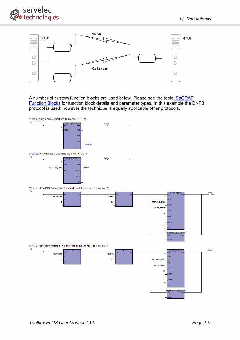
11. Redundancy
Toolbox PLUS User Manual 4.1.0 Page 197
A number of custom function blocks are used below. Please see the topic ISaGRAF Function Blocks for function block details and parameter types. In this example the DNP3 protocol is used; however the technique is equally applicable other protocols.
RTU1 RTU7Active
Redundant

11. Redundancy
Toolbox PLUS User Manual 4.1.0 Page 198
In this example, traffic was switched from one port to another if a failure was detected. The same method could also be used to switch from a direct to an indirect route. For example, if a direct radio link between two distant RTUs was not available then the sending RTU could fall back to forwarding traffic via an intermediate RTU. This application would use very similar logic, but would change the TYPE and VIA parameters to KF_SET_ROUTE, rather than PORT.
11.4 Redundant PCs Two or more PCs running SCADA or Toolbox PLUS software can be connected to the one RTU as illustrated below. All the PCs can poll the same data and set the same outputs. If one PC fails, the other PCs will continue to operate normally.
Each PC can be assigned its own RTU port or all the PCs can share one Ethernet port by using an Ethernet Network. Note: a CP-30/MC-31 Ethernet port can handle communications with up to four devices or RTUs simultaneously.
All the PCs can run the same SCADA software configurations with one exception. Each PC must be assigned a unique RTU address in the range 65521-65535 to prevent communication conflicts. To configure this, click the Connection toolbar button. The example below configures Toolbox PLUS to use address 65534. Toolbox PLUS uses address 65535 by default.

11. Redundancy
Toolbox PLUS User Manual 4.1.0 Page 199

12. Security
Toolbox PLUS User Manual 4.1.0 Page 200
12. Security
12.1 Overview This section describes the facilities provided by Toolbox PLUS for restricting access to projects and RTUs.
Good security practice dictates that a user be restricted to the minimum set of system features necessary to perform their role. To this end, Toolbox PLUS supports role based access control.
By default, a Toolbox PLUS project is unsecured, and has no access restrictions. If you choose to make a project secured then one or more user names may be created, assigned roles and saved. Thereafter, the project can only be opened or edited if a valid user name and password are specified, and the user’s defined role allows the requested operation.
If a secured project is loaded and a connection is made to an RTU, the RTU itself will become secured. This means that:
• In order to access the RTU (check status, download new configuration, etc.) you need to enter a valid user name and password.
• Only the original project, or one derived from it, may be downloaded to the RTU.
• The only way to return the RTU to its original unsecured state is to perform a factory reset.
12.2 Security Policies Each secured project includes a security policy, which is essentially a list of authorised user names, their encrypted passwords (password hashes) and their assigned role(s).
If you create a brand new project and secure it, then it will have its own security policy, which is unique to it. However, any project copies or variants derived from a secured project will share the same security policy. If you create and secure “Project A”, then save a copy called “Project A1”, then make some changes and save the result as “Project A2” then all three projects will share the same security policy, as they are all derived from the same original project. If you create a new project, “Project B”, from scratch then it will have its own separate security policy.

12. Security
Toolbox PLUS User Manual 4.1.0 Page 201
Thus while in some respects the security policy can be thought of as just another group of configuration settings within a project, it does have some special properties. In particular, a project’s security policy is “permeative”. This means that changes to the policy (such as adding users or changing passwords) can automatically “permeate” through the system – between different copies or variants of the project and between different RTUs.
Copies of a project’s security policy may exist in a number of different physical locations:
• Within the project folder itself (along with all of the other configuration settings)
• In the PC’s policy store (a special location on the PC’s local hard disk)
• On the RTUs defined by the project
Changes made to one copy of the security policy will be automatically merged with other copies at the first opportunity. “Merging” means that the most recent change to a particular setting will be automatically applied to all accessible copies. This merging of security policies occurs:
• When a secured project is opened – the policy in the project is merged with the policy in the PC policy store
• When you connect to a secured RTU – the policy in the project is merged with the policy read from the RTU
In both cases, the resulting merged security policy is then used to authenticate the user.

12. Security
Toolbox PLUS User Manual 4.1.0 Page 202
The practical upshot of this is that:
• If you change a project’s security policy and save the project, then when you subsequently open the project, or any other copies or variants on the same PC, then the new security policy will apply.
• If you download the changed project to an RTU, then when you subsequently connect to the RTU from any PC then the new security policy will apply.
See Security Policy Distribution Scenarios for more information on how security policies are updated in a number of common scenarios.
12.3 Project Tamper Detection When opening a project, Toolbox PLUS will check whether any project files have been altered or deleted since the project was last opened. This applies to all projects, both secured and unsecured. If an altered file is detected, the project’s security policy will be removed and the project can be opened as an unsecured project.
This has no consequence if the project was already unsecured, but if the project was secured then whilst it can still be viewed and edited, it will not be able to be used with any previously secured RTUs.
To avoid this warning being triggered:
• Do not copy a project folder while the project is open in Toolbox PLUS.
• Do not add, remove, or edit files in a project folder.
• Do not attempt to open the project’s database (.mdb) files using an external database application.
12.4 Security Policy Distribution Scenarios This section provides some examples of how security policies are transferred between project copies and RTUs.

12. Security
Toolbox PLUS User Manual 4.1.0 Page 203
12.4.1 Securing an RTU
In this scenario a project is created and secured. The RTU is currently unsecured (it has no security policy), and is not connected to Toolbox PLUS.
A connection is then made to the RTU (e.g. to check status, or in preparation to download configuration). The user is warned that the RTU will be secured, and if they agree then it will become so. Note that only the security policy on the RTU has changed at this point; it is still running its original configuration.
The configuration is then downloaded to the RTU.
An unrelated project is then opened in Toolbox PLUS. Any attempt to connect to the RTU is rejected, because the security policy does not match.

12. Security
Toolbox PLUS User Manual 4.1.0 Page 204
12.4.2 Project Copies on Same PC
In this scenario, a secured project is once again created and saved. Behind the scenes, a copy of the policy is automatically saved to the PC’s policy store.
A copy is then made of Project A, and Project A is closed. In the new copy, the configuration is edited and an additional user is added to the security policy. Note that the copy of the security policy in the PC’s policy store is automatically updated.
The new project is then closed and Project A reopened. Its security policy is automatically updated with the second user’s details, so that user will now be able to open Project A.
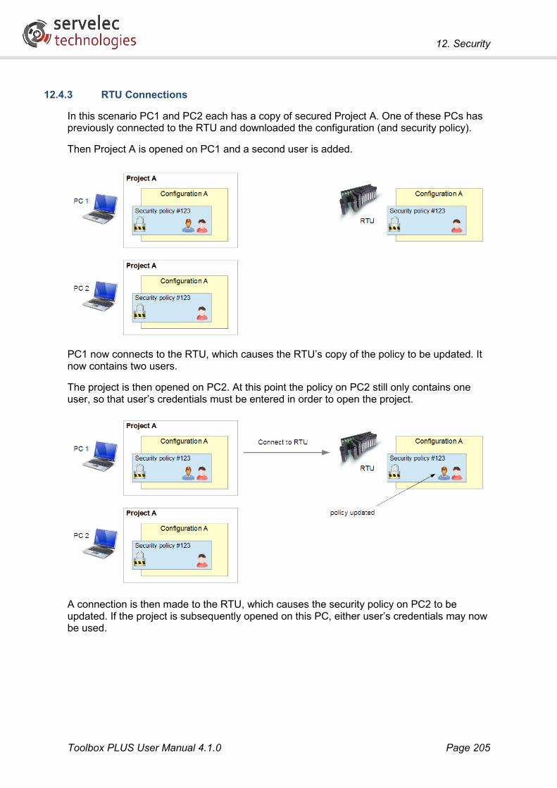
12. Security
Toolbox PLUS User Manual 4.1.0 Page 205
12.4.3 RTU Connections
In this scenario PC1 and PC2 each has a copy of secured Project A. One of these PCs has previously connected to the RTU and downloaded the configuration (and security policy).
Then Project A is opened on PC1 and a second user is added.
PC1 now connects to the RTU, which causes the RTU’s copy of the policy to be updated. It now contains two users.
The project is then opened on PC2. At this point the policy on PC2 still only contains one user, so that user’s credentials must be entered in order to open the project.
A connection is then made to the RTU, which causes the security policy on PC2 to be updated. If the project is subsequently opened on this PC, either user’s credentials may now be used.
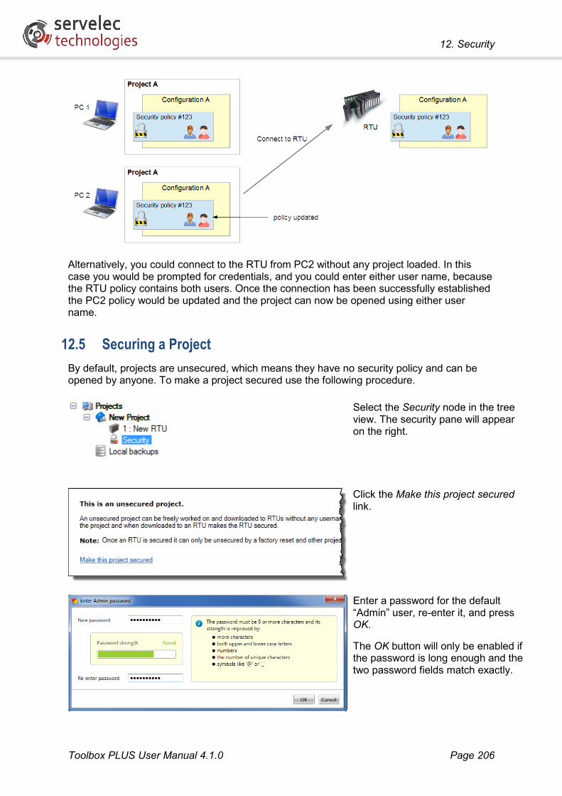
12. Security
Toolbox PLUS User Manual 4.1.0 Page 206
Alternatively, you could connect to the RTU from PC2 without any project loaded. In this case you would be prompted for credentials, and you could enter either user name, because the RTU policy contains both users. Once the connection has been successfully established the PC2 policy would be updated and the project can now be opened using either user name.
12.5 Securing a Project By default, projects are unsecured, which means they have no security policy and can be opened by anyone. To make a project secured use the following procedure.
Select the Security node in the tree view. The security pane will appear on the right.
Click the Make this project secured link.
Enter a password for the default “Admin” user, re-enter it, and press OK.
The OK button will only be enabled if the password is long enough and the two password fields match exactly.

12. Security
Toolbox PLUS User Manual 4.1.0 Page 207
See Passwords for important information about password selection.
Once a project has been secured, additional users and roles can be added, as described in Managing Users and Managing Roles.
12.6 Unsecuring a Project An administrator can make a secured project unsecured so that it no longer requires user login.
Note that this will not unsecure any RTUs that have already been loaded with the secured project. The only way to unsecure an RTU is to perform a factory reset.
Furthermore, once you unsecure a project, you will no longer be able to use that project to connect to an already secured RTU. If you re-secure the project it will effectively become a new project, and you will not be able to connect to any RTUs secured using the “old” project.
To unsecure a project:
Ensure that you are logged in as an administrator.
Select the Security node in the tree view. The security pane will appear on the right.
Click the Make this project unsecured link.
Take note of the warning, especially the part about the project no longer being able to connect to any already secured RTUs.
Press Yes to continue.

12. Security
Toolbox PLUS User Manual 4.1.0 Page 208
Enter the password for the currently logged in administrator, and press OK.
12.7 Role Based Access Control Role Based Access Control (RBAC) allows an administrator or manager to create new users and specify what they can do with a project. This feature is enabled when a project is secured.
Users are people that are authorised to access the project and/or the RTU. Each user has a user name and a password. When a project is secured, one user is automatically created, called Admin. This user has full control over the project and RTU, and cannot be deleted. Any number of additional users can be created.
Roles are the functions performed by particular users. Each user can be assigned one or more roles. By default, four roles are created: Administrator, Manager, Engineer and Maintenance. The latter three roles may be deleted if desired, and new roles may be added.
Permissions are particular functional areas to which access can be permitted or denied. Each permission generally covers a number of specific operations. For example, the Download permission covers opening IsaGRAF, downloading new configuration and logic, and downloading new firmware. Three permissions are currently defined: Manage Users, Configure and Download.
A user name and password must be entered whenever a secured project is opened. This is also required if you attempt to connect to a secured RTU with no project selected in Toolbox PLUS.

12. Security
Toolbox PLUS User Manual 4.1.0 Page 209
12.8 Roles and Permissions Permissions are not assigned directly to users. Instead, each role implies a particular set of permissions, so that when you assign a role to a user you are granting them a particular set of permissions. The following table summarises the permissions associated with each of the default roles:
Role
Man
age
user
s
Con
figur
e
Dow
nloa
d
A user having this role…
Administrator …can do anything. This role cannot be deleted
Manager - - …can add/remove users and roles
Engineer - …can create/edit/test/download configuration and logic, and download firmware
Maintenance - - …can download existing configuration, logic or firmware
(no roles) - - - …can view project and check RTU status
It is possible to delete, or change the permissions associated with, any of the above roles, apart from Administrator. It is also possible to define new roles.
The following table spells out in more detail which operations are allowed for each permission:
Permission
View
pro
ject
RTU
sta
tus
Upl
oad
serv
ice
repo
rt
Cha
nge
conf
ig/lo
gic
Add
/rem
ove
user
s/ro
les
Ope
n Is
aGR
AF
Dow
nloa
d co
nfig
/logi
c
Dow
nloa
d fir
mw
are
Save
pro
ject
Uns
ecur
e pr
ojec
t
Manage users - - - -
Configure - - - -
Download - - - -
(none) - - - - - - -
It is not possible to change the permitted operations assigned to each of the above permissions.
12.9 Managing Users When a project is secured, a Users node will appear in the tree view. Selecting this will display a list of all currently defined users. Initially, this list will have only one entry: Admin, the default administrator.
12.9.1 Adding a User
To add a new user:

12. Security
Toolbox PLUS User Manual 4.1.0 Page 210
Right click on the Users node and select New User.
If Users is not visible in the tree, make sure that the project has been secured and that you are logged in as Admin or a user with the Manage Users permission.
Enter a user name. This can either be the user’s full name, or some abbreviation. It will need to be entered each time that the user opens the project. Press OK.
A random initial password will be generated for the user. The Copy link will copy the password to the clipboard, so it can then be forwarded to the user. Alternatively, you can ignore the initial password and manually set a password for the user later in the process.
The Users pane contains a list of all defined users, which should now contain the newly created user. Notice that the user has also been added to the tree view.
Click on the link in the User name column to edit the user’s details. This will bring up the user details pane:

12. Security
Toolbox PLUS User Manual 4.1.0 Page 211
On this screen you can:
• Enter a description and/or email address for the user. These are for information only and are not used by Toolbox PLUS.
• Select the role(s) for the user, using the checkboxes on the right. As you select these, the Permissions section will change to reflect the permissions that the user will have. Note that the role for the default Admin user cannot be changed.
• Set a password for the user, using the Change password link. It is necessary to re-enter your administrator password before entering and user’s new password.
• Control whether or not the user must change their password when they first open the project. This option is enabled by default for users other than Admin.
12.9.2 Deleting a User
An administrator or manager may delete users from a project. The default Admin user cannot be deleted.
Note: Once a user has been deleted, the same user name may not be used again for this project.
To delete a user from a project:
Right click on the user to delete and select Delete User (or press the Del key).
You will be asked to confirm the deletion.
12.10 Managing Roles Adding and deleting roles is much the same as adding and deleting users. An administrator or manager may edit or delete the default roles (except Administrator), and may add new roles.

12. Security
Toolbox PLUS User Manual 4.1.0 Page 212
12.10.1 Adding a Role
To add a new role:
Right click on the Roles node and select New Role.
If Roles is not visible in the tree, make sure that the project has been secured and that you are logged in as Admin or a user with the Manage Users permission.
Enter a name for the role. Press OK.
The Roles pane contains a list of all defined roles, which should now contain the newly created role. Notice that the role has also been added to the tree view.
Click on the link in the Name column to edit the role. This will bring up the role details pane:

12. Security
Toolbox PLUS User Manual 4.1.0 Page 213
On this screen you can:
• Enter a description for the role. This is for information only and is not used by Toolbox PLUS.
• Select the permission(s) that users with this role will have.
• View or select the users (other than Admin) that have this role, using the checkboxes on the right.
12.10.2 Deleting a Role
An administrator or manager may delete roles from a project. The Administrator role cannot be deleted.
To delete a role from a project:
Right click on the role to delete and select Delete Role (or press the Del key).
You will be asked to confirm the deletion.

12. Security
Toolbox PLUS User Manual 4.1.0 Page 214
12.11 Managing a Secured RTU
12.11.1 Securing an RTU
If you load a secured project and then connect to a previously unsecured RTU, the RTU will become secured. This means that:
• A copy of the project’s security policy will be stored on the RTU, and will be updated any time a connection is attempted.
• The RTU is now tied to that particular project. Only the configuration and logic defined in that project, or one derived from it (e.g. using Save As), will be able to be downloaded.
• If you connect to the RTU with no project loaded, you will be prompted for username and password.
• The only way to return an RTU to its original unsecured state is to perform a factory reset.
In other words, a number of restrictions come into force once you secure an RTU. A warning message will therefore be displayed when you first attempt to connect to an unsecured RTU:
If you select Yes, the RTU will become secured, even if you don’t actually download the project’s configuration to it. This can be used to secure a new RTU processor, which can then be placed in stock. This can be used to prevent any unauthorised firmware downloads.
12.11.2 Connecting to a Secured RTU
Connecting to a secured RTU is much the same as connecting to an unsecured RTU. First, open the correct project. Being a secured project, you will be prompted for username and password. Once the project has loaded you can perform the desired function as you would normally, e.g. get status or download configuration.
If the project file is not available, you can still check the status of an RTU or download firmware by connecting to it with no project selected in Toolbox PLUS. In this case you will be prompted for username and password, which will be validated against the policy stored on the RTU.
If you connect to the RTU while a project is loaded, Toolbox PLUS will verify that the security policy on the RTU came from the currently loaded project, or a variant of it. If not, an error is displayed and the requested function is not performed:

12. Security
Toolbox PLUS User Manual 4.1.0 Page 215
At this point, in order to connect to the RTU your options are:
• Locate and open the original project used to secure the RTU. You don’t need the exact same version, but the project must have been derived from the original project. (Note that a project that has been unsecured, then resecured, is treated as an entirely new project.)
• Connect to the RTU with no project selected. You will be prompted for username and password, as described above.
• Perform a factory reset on the RTU, which will return it to the unsecured state.
The following table summarises the restrictions which will be enforced when you connect to an RTU, depending on the state of the selected project in Toolbox PLUS, and the state of the RTU.
Selected project RTU Action
None Not secured Connection allowed Not secured Not secured Connection allowed Secured Not secured Secures RTU (user is prompted) None Secured Prompt for username and password Not secured Secured Connection denied Secured (policy A) Secured (policy A) Connection allowed Secured (policy A) Secured (policy B) Connection denied
As noted in Security Policies, when you connect to a secured RTU the three copies of the project security policy (on the RTU, the PC policy store and the project folder) will be merged. For each entry in the policy (e.g. each user) the most recent details will be selected. The updated policy is then automatically written back to the policy store and the RTU.
Thus even a “get status” operation may cause the policy on the RTU to be updated, if the policy details on the PC are more recent than those on the RTU.
12.11.3 Unsecuring an RTU
The only way to unsecure an RTU is to perform a factory reset. This ensures that only a person with physical access to the RTU can unsecure an RTU.

12. Security
Toolbox PLUS User Manual 4.1.0 Page 216
12.12 Maintaining Security
12.12.1 Passwords
In a secured project every user must have a password. Passwords secure the system and must be kept secret.
As noted above, a project’s security policy (which contains all user names and passwords) may exist in three different places: the project folder, the PC policy store, and the RTU. In each case the policy details are encrypted, and are never transmitted in plaintext form. Within the policy, passwords are further encrypted.
However, encryption is only as good as the password used. If a password can be guessed then an attacker will be able to impersonate an authorised user and may gain access to the project and associated RTUs.
This is particularly important because the PCs on which projects are stored, and Toolbox PLUS is run, may not always be secure. If a skilled attacker obtains a copy of a project and locates the security policy then they can run “password cracking” software which can often guess passwords in a surprisingly short time, using trial and error and a number of clever algorithms.
The primary defence against this is to use a strong password. Passwords should:
• have at least 8 characters, preferably more
• not be a word or name which might be found in a dictionary – including words with zero substituted for ‘O’ and similar common tricks
• have a mix of upper case, lower case, numbers and punctuation
One method of creating strong memorable passwords is to create an acronym, e.g. “Ih1Bd&1Gc!” (“I have one black dog and one ginger cat!”) will be quite resistant to password cracking.
Toolbox PLUS gives an indication of password strength when you enter a new user password. Using passwords rated less than “good” is not recommended.
Note that because Toolbox PLUS only stores an encrypted version, or “hash”, of your password, it is not possible to recover a forgotten password. It is possible to reset the password on a project, but you will need to contact our support team.
12.12.2 Other Considerations
As well as using strong passwords, there are a number of other considerations when securing a system. The following list is not exhaustive.
• Ensure that physical access to the RTU is restricted. If an attacker can factory reset an RTU then it will revert to the default unsecured state, and they will be able to connect to it without needing any password.
• Don’t create more users than you need. Each additional password in the policy file increases the chance of an attacker guessing one. Be especially frugal in creating users with Administrator role.
• Encourage users to change their password regularly. In Toolbox PLUS an administrator can set an option to force a user to change their password on next login.

12. Security
Toolbox PLUS User Manual 4.1.0 Page 217
• Restrict access to copies of project files – centralise storage rather than having copies on many PCs. In any case, this is desirable from the point of view of version control.
• If contractors require temporary access to projects or RTUs, give them unique user names (don’t just give them the Admin password!) and ensure they are removed promptly once the work is complete. The automatic and “permeative” policy updates help in this regard – if the policy on an RTU is updated to remove a user then they will no longer be able to connect to it, even though they may still be listed in the policy within their copy of the project.
• Do not connect the RTU local network to the outside world. If remote wide area access is required, then ensure that a suitable firewall is in place to block all incoming connection attempts other than from specifically authorised computers or networks.
• Use DNP3 Secure for telemetry (see Require authentication for critical functions setting in DNP3 protocol settings).

13. Local Backups
Toolbox PLUS User Manual 4.1.0 Page 218
13. Local Backups
13.1 Overview When working on a large project it is recommended to save backup copies periodically. This helps reduce the amount of work lost in the event of project corruption due to power failure or other cause. It also provides a form of basic version control, allowing you to roll back to an earlier version if required.
The Local Backup feature in Toolbox PLUS makes it easy to save and restore project backups.
Project backups are complete copies of the project, including configuration settings, logic and security policy. They are stored in a special area of the PC’s local hard disk.
To view a list of currently stored backups, click on Local backups in the tree view.
13.2 Making a Backup To create a backup of the currently loaded project:
Right click on the project name and select Backup.
Alternatively, select File Backup Project from the main menu bar.
Enter a description for the backup (optional) and press OK.

13. Local Backups
Toolbox PLUS User Manual 4.1.0 Page 219
If the project has unsaved changes, you will be prompted to save it, which you can do by clicking Save.
If you now select the Local backups tree node, the new backup should be visible:
For each stored backup, this table indicates:
• whether the project is secured
• the name of the project
• the date the backup was made
• the version of Toolbox PLUS in use when the backup was mode
• if the project was secured, the user that opened the project and created the backup
• the user-entered description of the backup.

13. Local Backups
Toolbox PLUS User Manual 4.1.0 Page 220
When a project is saved, Toolbox PLUS may sometimes suggest that a backup be made:
If you click Yes then a backup will be made, as described above.
13.3 Restoring a Project To restore a project from a backup, right click on the backup from the table on the Local backups pane, and select Restore:
The project will now be saved and opened, with a suffix added to the name (e.g. “Wizzo Energy - 1") so that it doesn’t overwrite the original project. If the project is secured (see Security), you will be prompted for a username and password, the same as if you were opening the file normally.
When a project is restored, its security policy will also be restored. As is the case when any project is opened, its policy will be merged with that in the PC’s policy store, which may cause the restored project’s policy to be updated (see Project Copies on Same PC). For example, if you create a backup, then change your password, then later restore the backup, then the restored project’s security policy will contain your updated password.
The restored project will be saved to the Toolbox PLUS default project directory, which is under the current Windows user’s Documents folder.
You also have the option to export the backup as a zip file, which can be saved to any folder.

14. Connecting to an RTU
Toolbox PLUS User Manual 4.1.0 Page 221
14. Connecting to an RTU
14.1 Cables To connect a PC directly to an RTU, an Ethernet crossover cable is normally required as illustrated below, although some modern PCs may also work with a straight through cable. If connecting to an Ethernet hub or switch, a straight through cable or a crossover cable can be used.
By default, the IP address of the RTU’s main Ethernet port is set to 192.168.0.1. This may not be suitable for connecting via an existing Ethernet network – check with your network administrator. If this is the case then you will need to perform the initial setup using a direct crossover cable connection (or a local Ethernet switch, not connected to the main network). The CP-30 should not be connected to the existing Ethernet network until it has been configured with an IP address that is compatible with the network.
If required, the CP-30 can be reset it to its factory settings (including setting its IP address to 192.168.0.1) by performing a factory reset.
The above cables are industry standard and are readily available. Once a cable is installed, the PC’s LAN port needs to be setup as detailed in the LAN Port Setup.
If the RTU has a Serial option port and the port has already been configured (by first using Ethernet communications), then Toolbox PLUS can use Serial communications to the RTU.

14. Connecting to an RTU
Toolbox PLUS User Manual 4.1.0 Page 222
Both the RTU and the PC are DTE (Data Terminal Equipment) devices, so a serial cross-over (or null modem) cable will be required.
The easiest option is to use a standard straight through Ethernet cable, along with an ADP-05 serial adapter (optional accessory), as shown in the diagram below. This adapter has a female RJ-45 socket on one side and a female DB9 connector on the other (wired to suit a PC serial port). If your computer does not have a serial port then a USB to serial adapter can be used.
14.2 LAN Port Setup To initially communicate with the RTU, the PC’s LAN port must be enabled and setup to communicate with the RTU’s default IP address (192.168.0.1) as detailed below.
For Windows 7: Open Control Panel, select Network and Sharing Center, then Change adapter settings.
For Windows XP: Open Control Panel, select Network Connections.
This will show a list of the available network adapters in your PC. Identify the one corresponding to the RTU connection and confirm that it is enabled. If it is marked “Disabled”, right click and select Enable.

14. Connecting to an RTU
Toolbox PLUS User Manual 4.1.0 Page 223
Once the LAN port is enabled, right-click the LAN port again and select Properties.
Select Internet Protocol (TCP/IPv4) and then click Properties.
Set the IP address and subnet mask as shown. Note that any unused address in the range 192.168.0.2 to 192.168.0.254 can be used for the PC.
Press OK to save the settings.

14. Connecting to an RTU
Toolbox PLUS User Manual 4.1.0 Page 224
Verify the connection by starting a Windows command window and typing: ping 192.168.0.1
The results should indicate that replies are being received from the RTU. If not, check your cables and LAN settings.
14.3 Connection Parameters The Connection toolbar button is used to define how Toolbox PLUS will communicate with the RTU.
Normally, Toolbox PLUS will use the selected RTU’s configured Port 1 Ethernet IP address. However, sometimes you will need to override this – e.g. if you have changed the IP address in the configuration then you will need to tell Toolbox PLUS to connect using the old address in order to load the new configuration.
If the Port 1 IP address is not selected, the button label will no longer read “Connection”, but will indicate the selected connection method, e.g. if an alternative IP address is selected then the IP address will be displayed.
Pressing the Connection button will display the Connection to RTU dialog, which has the settings listed below.
Use RTU IP address information: When selected, Toolbox PLUS uses the IP address configured for the processor Port 1.
Use the following IP address information: When selected, Toolbox PLUS uses the specified IP address.
Use the following serial port information: When selected, Toolbox PLUS uses the specified serial port (COM1, COM2 …) and speed (9600, 19200, 38400, 57600 or 115200 bps) to communicate with the RTU using the Kingfisher protocol.
Note: If the CP-30’s IP address is unknown then it can be reset to the factory default of 192.168.0.1, as described in Factory Reset.
The Advanced tab contains additional settings:

14. Connecting to an RTU
Toolbox PLUS User Manual 4.1.0 Page 225
Network Address: (1-65535) Because the PC is treated like another RTU in the network, it must have its own unique address. Addresses 65521 to 65535 are reserved for Toolbox PLUS. If two or more PCs running Toolbox PLUS are connected to the same RTU, each PC should have its own unique address to avoid communication conflicts.
Via address: (0-65535) When using a network of RTUs, this is the address of the first RTU to communicate through. Address 0 [default] disables this function.
Timeout (ms): The time to wait for the RTU to respond to messages. This setting may need to be lengthened when communicating using a slow serial link (e.g. a setting of at least 4000ms when using 1200 baud)
Retries: The maximum number of attempts (after the first attempt) Toolbox PLUS will make at sending a message to the RTU if the previous attempts have failed.
Repeat Rate: This allows a delay to be inserted between message attempts.
Always use Kingfisher protocol for file transfers: When enabled, Toolbox PLUS uses the Kingfisher protocol when downloading firmware and configurations over Ethernet or serial connections. When disabled, Toolbox PLUS uses the SSH internet protocol, which is significantly faster.
Using the SSH protocol is normally preferable. However, Kingfisher protocol will need to be used if:
• A serial connection is used to connect to the RTU
• A configuration or firmware is being downloaded to a CP-30 via an MC-31 Ethernet port
• A configuration or firmware is being downloaded to a CP-30 via another RTU
14.4 Discovery The Discovery toolbar button tells Toolbox PLUS to try to locate the RTU on the local Ethernet or serial network.
14.4.1 Ethernet
For Ethernet, Toolbox PLUS will send out a broadcast packet on the local subnet and collect any replies from RTUs.
Press Search to initiate the discovery process. The RTU address and IP address will be displayed for all RTUs that were found.

14. Connecting to an RTU
Toolbox PLUS User Manual 4.1.0 Page 226
Note that this will only work if the RTU’s current IP address is set to a value which is compatible with the local subnet. For example, if the RTU and your PC are connected to the 192.168.0.x LAN, but the RTU’s IP address is set to 10.2.3.12, then it will not be detected.
Once the RTU’s IP address and RTU address have been determined, the Status button can be used to check that communications are working. See Status for more details.
14.4.2 Serial
Select the Serial tab to search for RTUs connected via a serial cable.
First select the desired PC port in the control on the left, or choose All Ports to scan all available PC serial ports. Then click Search.
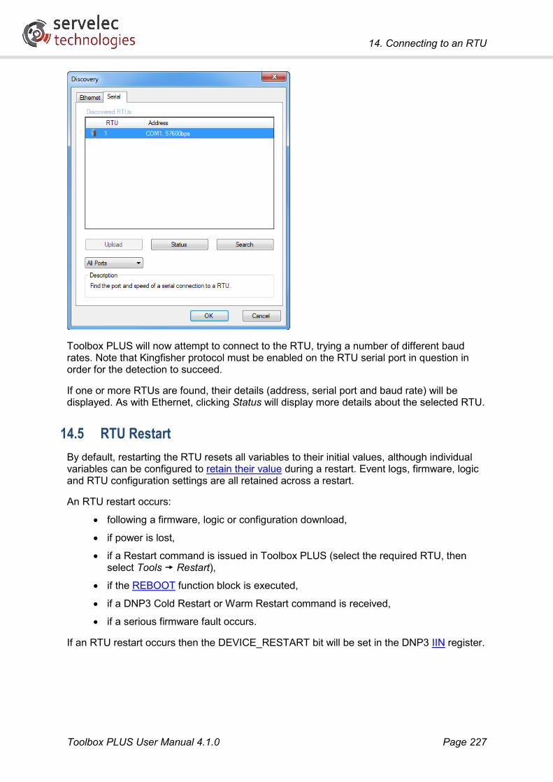
14. Connecting to an RTU
Toolbox PLUS User Manual 4.1.0 Page 227
Toolbox PLUS will now attempt to connect to the RTU, trying a number of different baud rates. Note that Kingfisher protocol must be enabled on the RTU serial port in question in order for the detection to succeed.
If one or more RTUs are found, their details (address, serial port and baud rate) will be displayed. As with Ethernet, clicking Status will display more details about the selected RTU.
14.5 RTU Restart By default, restarting the RTU resets all variables to their initial values, although individual variables can be configured to retain their value during a restart. Event logs, firmware, logic and RTU configuration settings are all retained across a restart.
An RTU restart occurs:
• following a firmware, logic or configuration download,
• if power is lost,
• if a Restart command is issued in Toolbox PLUS (select the required RTU, then select Tools Restart),
• if the REBOOT function block is executed,
• if a DNP3 Cold Restart or Warm Restart command is received,
• if a serious firmware fault occurs.
If an RTU restart occurs then the DEVICE_RESTART bit will be set in the DNP3 IIN register.

14. Connecting to an RTU
Toolbox PLUS User Manual 4.1.0 Page 228
14.6 Factory Reset The procedure described in this section will reset a CP-30/MC-31 module to its factory default settings. That is:
• Main Ethernet port IP address is set to 192.168.0.1, subnet mask 255.255.255.0
• All other configuration settings are reset to defaults.
• All logic is cleared.
• All security settings are removed, i.e. the RTU will become unsecured.
• All event log entries and retained variables are cleared.
• System clock setting may be cleared (depending on reset method used).
• System diagnostic log is retained.
Note that upgrading firmware does not perform a factory reset (although it will clear the event log and any retained variables).
The factory reset procedure depends on the module type and hardware version. For CP-30/ MC-31 modules, you may have version 1 or version 2 hardware. Version 2 hardware can be identified by the presence of a 2-pin link header on the front edge of the module, just below the LED display.
14.6.1 CP-30/MC-31 – Version 2 Hardware
To factory reset a version 2 module (requires firmware 3314 or later):
1. Switch off power to the RTU rack, or remove module from rack.
2. Short together the 2-pin link header on the front edge of the module, using a metal screwdriver or a jumper link.
3. With the pins still shorted together, turn on the RTU power (or re-insert module).
4. Remove the screwdriver or link.
14.6.2 CP-30/MC-31 – Version 1 Hardware or Old Firmware
The following procedure is used to factory reset a version 1 module, or a version 2 module with firmware older than 3314. Note that this method will cause the system time to be reset.
1. Remove the module from the rack
2. Remove the jumper link from the header on the rear edge of the module (adjacent to the backplane connector)
3. Wait at least 5 minutes
4. Replace the jumper link and return the module to the rack.
Note: If you remove the battery or battery link then after replacing it the module should be plugged into a backplane and powered up for at least one second. Failure to do this may result in much shorter battery life.

15. Download
Toolbox PLUS User Manual 4.1.0 Page 229
15. Download
15.1 Overview Toolbox PLUS can be used to create a configuration for an RTU while “offline”, i.e. without actually having the RTU connected. Ultimately, however, it is necessary to connect to the RTU in order to download the newly created configuration and logic programs to the RTU.
The general workflow when configuring an RTU is as follows:
1. Define configuration in Toolbox PLUS (define module layout, adjust settings)
2. Define logic programs in ISaGRAF Workbench
3. “Build” the configuration and logic. The result is a set of files which the RTU can understand. This will be done automatically if the configuration or logic have changed. It can also be triggered manually, using the Build toolbar button. See also ISaGRAF Overview.
4. Download these compiled files to the RTU.
5. Restart the RTU (this will happen automatically)
Note that it is not possible to make online changes to the configuration of a running RTU. Any configuration change needs to be built, downloaded and the RTU restarted, as noted above.
Toolbox PLUS can also be used to download new firmware to the RTU.
15.2 Downloading Configurations
15.2.1 Firmware Compatibility
As noted in Firmware, it is important to be aware of any potential compatibility issues between Toolbox PLUS and the RTU’s firmware.
The current version of Toolbox PLUS can be used to download configuration and logic files as follows:
RTU Firmware Version Configuration/logic download
Earlier than 2874 Not supported (use an earlier version of Toolbox PLUS) 2874 or later Existing projects only 2981 or later Existing or new projects. Some function blocks or other features
described in this manual may not be supported, or may work differently. Check firmware release notes.
4165 or later Existing or new projects. All features except those marked “requires recent firmware” are supported. Check firmware release notes.
Note that this version of Toolbox PLUS can read the status from an RTU with any firmware version. It can also upgrade the RTU firmware from any version (subject to any special procedures described in the firmware release notes).

15. Download
Toolbox PLUS User Manual 4.1.0 Page 230
15.2.2 Connection
In order to download a new configuration, the required project must be open in Toolbox PLUS, and the required RTU selected.
Main CP-30 Ethernet port
The simplest and fastest method of downloading a configuration to the CP-30 is to use the main Ethernet port on the CP-30.
Before attempting to download the configuration, ensure that the connection parameters are set correctly. In particular:
• If the main port IP address set in the configuration is the same as the CP-30’s current IP address then select Use RTU address information. If the new configuration will change the main port IP address then select Use the following IP address information, and enter the CP-30’s current IP address.
• On the Advanced tab, ensure that the Always use Kingfisher protocol checkbox is not ticked. The SSH protocol will then be used.
Other CP-30 Ethernet ports
It is also possible to update a CP-30’s configuration via a connection to a T3 Ethernet option card (installed as port 2 or 3 on a CP-30). The CP-30 must have been previously configured to enable the additional port and set its IP address.
Before attempting to download the configuration, ensure that the connection parameters are set correctly. In particular:
• Select Use the following IP address information, and enter the current IP address of the T3 Ethernet port.
• On the Advanced tab, ensure that the Always use Kingfisher protocol checkbox is not ticked. The SSH protocol will then be used.
Other connection options
With some caveats, it is also possible to update a CP-30’s configuration via an MC-31 port, or a serial connection, or via another RTU. The CP-30 must have been previously configured to enable the port and set its IP address or serial parameters.
Note: It is not possible to change the RTU’s address using these connection methods. The address (1-65520) set in the RTU Properties dialog must match the RTU’s current address.
Before attempting to download the configuration, ensure that the connection parameters are set correctly. In particular:
• If connecting to an MC-31 Ethernet port, select Use the following IP address information, and enter the current IP address of the MC-31 port.
• If connecting to a serial port, select Use the following serial port information and enter the current baud rate set for the serial port. (Note that the serial configuration downloads are only supported if the RTU port is configured for 8 data bits, no parity, 1 stop bit.)
• If connecting via an intermediate RTU, be sure to use the IP address or serial baud rate of the intermediate RTU (not the destination RTU) for the above settings. On the Advanced tab, set the Via address field to the address of the intermediate RTU.

15. Download
Toolbox PLUS User Manual 4.1.0 Page 231
• On the Advanced tab, ensure that the Always use Kingfisher protocol checkbox is ticked. The Kingfisher (KF) protocol will then be used.
15.2.3 Download
To download a new configuration to the RTU, click the Download toolbar button, then Configuration and Logic.
This command will download the RTU configuration (module definition and settings), and any logic programs (including Dictionary variables).
(It is also possible to download just the configuration, or just the logic, but this is generally not useful unless you are connected via a very slow communications link.)
The following operations will then occur automatically:
1. If necessary, the configuration and/or logic will be rebuilt.
2. The configuration files will be downloaded to the RTU
3. The RTU will extract and process the files
4. The RTU will restart
5. Toolbox PLUS will reconnect to the RTU and confirm that the update was successful (although see Reconnection below).
It is also possible to download the entire project file to the RTU, by selecting Configuration, Logic and Project. The project can then be retrieved from the RTU (using the Upload Configuration option on the Tools menu) at a later date, where it can be viewed or modified.
If the project file is not saved to the RTU then the Upload Configuration function can still reconstruct the basic configuration in Toolbox PLUS, but the logic programs will not be able to be loaded.
The downside of storing the project file on the RTU is that it can be quite large, so it will use up space on the RTU and increase the time taken to download new configurations.
15.2.4 Reconnection
If the newly downloaded configuration has changed the communications settings on the RTU (e.g. IP address, serial port baud rate) then Toolbox PLUS will not attempt to monitor progress or reconnect.
If this is the case then the following will be displayed once the files have been downloaded and the update process has commenced:

15. Download
Toolbox PLUS User Manual 4.1.0 Page 232
Wait for 1-2 minutes for the update to complete.
To verify the new configuration, click the Connection toolbar button then select the Use RTU address information option. Then press the Status toolbar button to check that you can communicate with the RTU using the new settings.
Note: If ISaGRAF logic is rebuilt and downloaded then any existing retained variables will be cleared.
15.3 Downloading Firmware
15.3.1 Overview
Firmware can be downloaded into a processor or communications module to upgrade functionality. The firmware version that is currently in the CP-30 or MC-31 can be checked using the Status command.
Note that the CP-30 and MC-31 use identical firmware.
When upgrading firmware, it is recommended that all CP-30 and MC-31 modules in an RTU be upgraded to the same version.
Upgrading firmware will preserve the current RTU configuration (including configured IP addresses). However, all logic will be cleared, as will all event logs.
Important: Firmware releases are always supplied with release notes, which describe the changes made and any special upgrade procedures which may be required. It is vital that you read the release notes before attempting any firmware upgrade.
Important: The process of upgrading firmware can take several minutes. To minimise the chance of the upgrade failing, firmware upgrades should be performed using a reliable communications link (e.g. Ethernet) and with a stable power supply to the RTU.
15.3.2 Connection
The simplest and fastest method of downloading firmware to a CP-30 or MC-31 is to use an Ethernet port – normally the main Ethernet port, but you can also use port 2 or 3 if you have a T3 Ethernet option card installed. The RTU must have been previously configured to enable the port and set its IP address (unless the main port is being used with its factory default IP address).
It is also possible to update a CP-30’s firmware via an MC-31 port, or a serial connection, or via another RTU. Note that this method will be significantly slower, and it is not possible to update MC-31 firmware using this method.
For MC-31, a direct Ethernet connection is required, and the SSH protocol must be used (ensure that on the Always use Kingfisher protocol checkbox is not ticked).
Before attempting to download the firmware, ensure that the connection parameters are set correctly, as described in Downloading Configurations.
15.3.3 Download
Before starting a firmware upgrade, be sure to read the release notes supplied with the new firmware. You should also determine the firmware version that you are upgrading from.

15. Download
Toolbox PLUS User Manual 4.1.0 Page 233
Special procedures may be required when upgrading from very old versions (earlier than version 2874), or when downgrading from recent versions – check the release notes for details.
The process for upgrading firmware on a CP-30 or MC-31 is as follows:
If no project is loaded then the Connection To RTU window will appear. Specify the IP address of the Ethernet port that firmware will be downloaded to. If a project is loaded then ensure that the correct RTU is selected.
The Select Firmware File window will appear. Select the firmware file to download into the CP-30 or MC-31. This will have a name such as CP30_MC31_firmware_v4165.tgz.
The following operations will then occur automatically:
1. The firmware package will be downloaded to the RTU
2. The RTU will extract and process the files, then restart
3. Toolbox PLUS will reconnect to the RTU and confirm that the update was successful.
Assuming an Ethernet link, this process will typically take around 5 minutes to complete.
Note: If you are upgrading or downgrading to an older firmware version (earlier than 4165) then the procedure is the same, but you may notice that the RTU restarts multiple times.
If your only connection to the RTU is via an MC-31, then the CP-30 firmware can still be upgraded by selecting the Kingfisher protocol (if you use SSH then you will actually upgrade the MC-31 firmware).
Upgrading Redundant Processor Systems
For a system with redundant CP-30 processors, you will need to upgrade the firmware for each processor separately.
When upgrading firmware using the default SSH protocol, the upgrade will occur regardless of whether the processor you are upgrading is currently the active or standby processor. In fact, if the CP-30 is the active processor then when it restarts after processing the first part of the upgrade it will come up as the standby, because the other CP-30 will have taken over during the restart. This should not affect the upgrade process.
Note: If you are upgrading or downgrading a CP-30 in a redundant processor system to an older firmware version (earlier than 4165), and doing so via an MC-31 port, it is essential that the other CP-30 is removed from the RTU during the upgrade. Otherwise, after the first part of the upgrade the other CP-30 will assume control, and the second part of the upgrade package will be directed to it (as the active RTU processor) rather than the CP-30 that is being upgraded. This will cause the upgrade to fail.
15.3.4 Reconnection
After performing a firmware upgrade, the existing configuration settings and ISaGRAF logic will be preserved. However, the event log and any retained variables will be cleared.

16. Viewing Data
Toolbox PLUS User Manual 4.1.0 Page 234
16. Viewing Data
16.1 Status The Status command reads the following information from the selected RTU:
• Basic details including RTU address and firmware version
• Current RTU Date and Time. This can also be set.
• Status of all detected I/O modules
• Communications statistics
Note that in order for the status request to be successful:
• The connection parameters (IP address or serial baud rate) must match the current actual settings in the RTU, and
• The RTU address in the configuration must match the RTU’s current actual address.
• If the RTU has been secured then either the correct project must be open in Toolbox PLUS, or you must enter valid username and password when prompted by the RTU.
If the RTU’s IP address or RTU address are not known then the Discovery command may be used. Failing that, the CP-30 can be reset to factory settings (address 1, IP 192.168.0.1) as described in Factory Reset.
To perform a status request, click the Status toolbar button. If no RTU is selected then you will be prompted for the IP address to use.
On the General tab:
RTU Address: The address of the currently connected RTU (1-65520)
Build Number: Firmware version number
User Flash Free (KB): The amount of free non-volatile memory available in the RTU
Installed components: Not used.
Refresh: Re-reads the information from the RTU.

16. Viewing Data
Toolbox PLUS User Manual 4.1.0 Page 235
On the Date & Time tab:
Current RTU Time: The current RTU time is displayed here, updated once per second, in the configured RTU time zone (if set).
Current PC Time: The current PC local time is displayed here, updated once per second.
Custom Time: A custom date/time may be entered here. Click on the required time component, then type a new value or use the up/down arrow buttons. The entered time is assumed to be in the RTU’s time zone.
Set RTU to PC Time: If Current PC Time is selected, this will set the RTU time to the current PC time (allowing for any time zone difference), which should immediately update the Current RTU Time field (see note below).
Set RTU to Custom Time: If Custom Time is selected, this will set the RTU time to the specified time, which should immediately update the Current RTU Time field (see note below).
Note: The time zone indicators (e.g. “UTC+10:00”) will only be displayed if the RTU time zone has been set.
Note: If the RTU time is changed by less than 10 seconds then the RTU will not change the time immediately; rather, it will very gradually adjust the time over the next few hours. This avoids sudden time steps in logged events.

16. Viewing Data
Toolbox PLUS User Manual 4.1.0 Page 236
On the Modules tab:
Slot: Slot number (1-64) containing a detected module.
Module: Module type
Version: Module firmware version (communications and I/O modules only)
Details: Displays context specific details of the currently selected module. The information presented will depend on the type of module.
Refresh: Re-scans the RTU for additional modules
Note: After installing or removing a module, it can take several seconds for the change to be recognised.
Note: Only slots for which a module has been configured will be scanned. This means that a module placed in an unconfigured slot will not be detected and will not appear in the displayed module list. If, however, no configuration at all has been downloaded to the RTU (e.g. a factory reset has been performed) then all slots will be scanned.
Sample module details display:
For an IO-3 module, the module status display shows the state of the 4 digital inputs, current readings for the 4 analog inputs, and provides buttons for toggling the 4 digital outputs and a field for setting the analog output level.

16. Viewing Data
Toolbox PLUS User Manual 4.1.0 Page 237
On the RTU Statistics tab:
This shows communications statistics recorded by the selected RTU. The statistics are the same as those reported by the KF_GET_COMM_STATS function block.
RTU Addresses: Statistics will be shown for communications attempted between the selected RTU and each RTU address in this list. An address of 0 will return aggregate statistics across all RTUs.
Find: Update displayed statistics.
Continuous: Continuously update displayed statistics.

16. Viewing Data
Toolbox PLUS User Manual 4.1.0 Page 238
16.2 Event Logs Events allow the RTU to record time and date stamped data. An event is recorded when:
• The KF_EVENT_LOG function block is executed.
• A class 1, 2 or 3 DNP3 variable changes in value. For analog inputs, the change must exceed the configured deadband.
• DNP3 events are received from another RTU, e.g. in response to a DNP3 class 1/2/3 poll request.
• Other events are received from another RTU, e.g. in response to a Kingfisher protocol event log request
• Events are read from a digital input module that supports Sequence-Of-Events recording (e.g. DI-10)
The number of events that can be recorded in the RTU memory is configurable on the RTU Properties dialog (max. 100,000 events).
Events stored in the RTU can be retrieved and viewed using Toolbox PLUS (as described below). DNP3 events can also be retrieved by a DNP3 master device, using the DNP3 protocol. The RTU can track event retrieval and confirmation for up to 4 different DNP3 master addresses.
16.2.1 Viewing Event Logs
To retrieve and view event logs:
• Select the RTU name in the navigation pane
• Select Event Log in the Stacked Menu Bar
• Select the Retrieve button
• Specify whether to retrieve All Events or the number of newest events to retrieve
16.2.2 Event Log Buttons
Apply Filter: Applies the configured filter settings when retrieving event logs, so that only those matching the filter will be retrieved.
Count: Queries the number of event logs currently stored in the RTU and displays the result (to the right of the Cancel button).
Filter: Configures the filter settings
Retrieve: Retrieves event logs from the RTU. This can retrieve all events or a configurable number of events.
Export: Saves the uploaded event logs into a CSV file (can be opened using Microsoft Excel).

16. Viewing Data
Toolbox PLUS User Manual 4.1.0 Page 239
Clear: Clears all the event logs in the RTU.
Cancel: Only available while retrieving event logs. Stops the uploading of event logs.
16.2.3 Event Log Parameters
Retrieved event logs are listed in column format, e.g.:
The various parameters that make up an event log are listed below.
Id: Unique index assigned to each event log by the RTU.
Timestamp: Date and time of the event log. If the RTU time zone has been set, these times will be displayed using that time zone. The time zone offset (eg “UTC+09:30”) will be shown in the column heading.
RTU: Address of the RTU that created the event log.
Name: Name of the variable that was logged.
Value: Value of the variable when logged.
Flags: Additional information available when using DNP3.
Type: Configured type of the event log. For DNP3, this is the event variation.
Priority: Configured priority of the event log. For DNP3, this is the event class.
16.2.4 Event Log Filter
To configure the Event Log Filter
• Select the RTU name in the navigation pane
• Select Event Log in the Stacked Menu Bar
• Select the Filter button
• Specify the General settings of the event logs to upload
• Select the Date Range tab to specify time and date settings of the event logs to upload
• Enable the filter by ticking Apply Filter.

16. Viewing Data
Toolbox PLUS User Manual 4.1.0 Page 240
• Select the Retrieve button to upload event logs that correspond to the filter settings
The event filter settings are shown below:
Max Number: (0 – 65535) Maximum number of event logs to retrieve (0=all)
RTU: (1-65520) Only event logs created by this RTU will be retrieved (0=all).
Type: (0-31) Only event logs matching this Type setting will be retrieved.
Priority: (0-7) Only event logs matching this Priority setting will be retrieved.
Range Start: The date and time of the oldest event log to retrieve.
Range Finish: The date and time of the newest event log to retrieve.
Range Start/Range Finish: Setting these dates allows users to isolate a time period. Users can select a date in the calendar, then select the buttons to update the start/finish date.
Clear Current: Sets the selected range to the start of the event log index
Update Current: Sets the selected rage to the current date
Range Start/Range Finish These textboxes are the summary of the requested period. Values of “01.01.1970” indicate “any date”.
16.3 RTU Time Zone The RTU incorporates a battery backed real time clock (RTC), which keeps track of the current calendar time. This is used to timestamp events, and may also be tested in logic to perform actions at particular times of day.

16. Viewing Data
Toolbox PLUS User Manual 4.1.0 Page 241
The RTU time can be set using the Date & Time tab on the RTU Status window, or via a DNP3 message from a SCADA system. It can also be synchronised to an NTP (Network Time Protocol) server or a GPS receiver connected to a DI-10-GPS module.
By default, the RTU time is not assumed to be in any particular time zone – that is, the time zone is “unspecified”. This means that:
• If you set the RTU time using Toolbox PLUS, the current local PC time will be sent to the RTU unmodified.
• Events written to the event log, or transmitted via DNP3, will be timestamped using the current RTU time. When viewing events in Toolbox PLUS or a SCADA system, the user needs to be aware of what time zone was used when the RTU time was set.
• If the RTU is configured to synchronise its time to an absolute time reference (e.g. NTP, GPS), the RTU time will need to operate using UTC (Coordinated Universal Time, which is essentially equivalent to Greenwich Mean Time). All event timestamps will then be displayed in UTC.
To prevent any ambiguity when interpreting timestamps, it is recommended that a time zone be configured for the RTU, using the RTU Properties dialog. If a time zone is set:
• The RTU system time will internally operate in UTC. All events (including DNP3 events) will therefore be stored and transmitted with UTC timestamps.
• If you set the RTU time using Toolbox PLUS, the current local PC time (or the custom time that you enter) will be automatically converted to UTC before being sent to the RTU.
• When setting the RTU time using Toolbox PLUS, the current RTU time will be displayed using the configured RTU time zone.
• In Toolbox PLUS, event timestamps will be displayed using the configured RTU time zone.
• Times displayed on the Date & Time tab and in the event log will include a time zone indicator, e.g. “UTC+10:00” (which indicates that the time zone is 10 hours ahead of UTC).
• An absolute time reference (e.g. NTP, GPS) may be used to correct the RTU time. This will not affect how times are displayed in Toolbox PLUS.
• The KF_GET_TIME function block will return the current time in the RTU’s configured time zone.
• The KF_GET_RTC function block returns the number of seconds since 00:00 UTC, 1 Jan 1970. This is therefore not affected by the RTU time zone setting.
Note that the configured RTU time zone is always a fixed offset from UTC. That is, it represents standard time; no adjustment will be made for daylight saving. Keep this in mind when viewing event timestamps, and if you use KF_GET_TIME to trigger actions at particular times of day.
If the firmware of the currently connected RTU does not support the timezone feature, Toolbox PLUS will ignore the configured RTU time zone and treat it as if it were set to “unspecified”.

16. Viewing Data
Toolbox PLUS User Manual 4.1.0 Page 242
16.4 Communications When troubleshooting RTU systems, it is frequently very helpful to be able to capture the actual message packets that are being sent and received. If a problem with the RTU is suspected the capture files can be forwarded to our support team for analysis.
Two main tools are generally used for this purpose:
• Toolbox PLUS Comms Analyzer feature
• Wireshark – a free and widely used packet capture PC application.
In general terms, Wireshark is more powerful, but Comms Analyzer can be used in a wider range of scenarios.
16.4.1 Comms Analyzer
Overview
The Toolbox PLUS Comms Analyzer works as follows:
1. The selected RTU is instructed to start capturing communications messages on a particular port.
2. From that point on, each time a message is sent or received, the information is returned to Toolbox PLUS, using a separate RTU port to the one being monitored.
3. Toolbox PLUS saves the received packets and allows them to be viewed.
The main limitations of Comms Analyzer are:
• It is not possible to capture traffic on the physical RTU port that is being used to connect to Toolbox PLUS
• Only basic packet decoding is performed (Wireshark’s packet decoding is much more extensive)
• There is a performance impact on the RTU being monitored and on the communications link between that RTU and Toolbox PLUS, while capture is enabled.
Using Comms Analyzer
To use Comms Analyzer, first select the RTU in the navigation pane, then click Comms Analyzer in the Stacked Menu Bar.
The controls for the Comms Analyzer are at the top of the workspace:
Port: This contains a list of all defined ports in the RTU. Select the one for which you want to capture traffic. Remember that it is not possible to capture traffic on the port that Toolbox PLUS is using to communicate with the RTU.
Start: Start capture on the selected port. This button changes to Stop while capture is in progress.

16. Viewing Data
Toolbox PLUS User Manual 4.1.0 Page 243
Export: Saves some or all the captured packets in CSV format. The generated file can then be opened in a text editor or spreadsheet application.
Clear: Deletes all captured packets.
Options: Allows a number of settings to be adjusted:
The following tabs are available:
Capture File: If Enable file capture is ticked then packet data will be continuously saved to capture files. This is useful if you need to leave the Comms Analyzer running for a long period of time in order to capture a rare event.
Columns: Allows some of the columns to be hidden
Message: Specifies how the various components listed in the Message column are separated
Hexadecimal: Specifies how the hexadecimal message data is formatted
Alphanumeric: Specifies how the alphanumeric message data is formatted
Other: Various other cosmetic display adjustments
To start capturing, click Start. Notice that while capture is active an animated overlay is shown on the RTU’s icon in the navigation pane.
A typical Comms Analyzer display is shown below:
This shows:
• An entry indicating the time at which capture was started, and the port being monitored
• Two incoming DNP3 polls from a master (address 111) to the local RTU (address 1), and the responses sent by the RTU.

16. Viewing Data
Toolbox PLUS User Manual 4.1.0 Page 244
The Message column provides a basic decode of the message. Note that it does not necessarily list everything you need to know about the message. For example, for a DNP3 message it lists the header fields and the first data object only.
The yellow highlight indicates that the packet is selected. By clicking on rows in conjunction with the Shift and Ctrl keys, you can select a range of packets, which can then be exported using the Export button.
16.4.2 Wireshark
Overview
Wireshark is a PC-based application which can capture all traffic sent or received by the PC’s Ethernet interfaces. It has extensive packet filtering capabilities, and can decode many different protocols.
The main limitations of Wireshark are:
• It can only capture Ethernet traffic.
• It can only capture traffic that is received or sent by the PC. Normally this means that it can only capture traffic sent to or by the PC. However, by using an Ethernet hub it is possible for the PC to “snoop” on Ethernet traffic sent from one RTU to another.
Snooping
In a modern Ethernet network, each device (PC, RTU, etc.) is normally connected to an Ethernet switch or router. The switch or router examines each packet that passes through it and directs it to the appropriate destination device. This means that if two RTUs and a PC are all connected to an Ethernet switch or router, then the communications between the two RTUs will be invisible to the PC, which means that Wireshark will not be able to capture them.
However, there is an older technology which can be used to connect devices on an Ethernet network, called a hub. Hubs broadcast each received packet to all connected devices. The devices will normally discard anything not addressed to them, with the exception of tools such as Wireshark, which can capture them.
The following diagram shows how a hub can be temporarily added to a network to allow Ethernet traffic sent between two RTUs to be captured.

16. Viewing Data
Toolbox PLUS User Manual 4.1.0 Page 245
In the top diagram, RTU1 and RTU2 are connected via an Ethernet switch, so the PC will not receive (and will therefore not be able to capture) any traffic except that addressed to it.
In the bottom diagram, RTU1 has been unplugged from the switch and plugged into a hub instead. The hub is also connected to the PC and to rest of the network via the switch. In this configuration anything sent to or from RTU1 (including traffic directed to RTU2) will be visible to the PC and will be able to be captured by Wireshark.
Using Wireshark
Download Wireshark from www.wireshark.org and install on your PC, then start it as you would any application.
The Wireshark website includes extensive documentation and tutorials. In general terms, however the procedure is to first select the correct Ethernet interface (if your computer has more than one) from the list on the Wireshark home screen, then press Start.
A typical Wireshark display is shown below:
Ethernet Switch
Ethernet Switch Non-switching HUB
RTU 1 RTU 2
RTU 1 RTU 2

16. Viewing Data
Toolbox PLUS User Manual 4.1.0 Page 246
This shows, from top to bottom:
• A list of all received or transmitted packets
• Details of the selected packet, with each protocol layer decoded (if possible)
• The raw data in the packet.

17. Appendices
Toolbox PLUS User Manual 4.1.0 Page 247
17. Appendices
17.1 Glossary
Byte A group of 8 bits. Each bit can be a 0 (off) or a 1 (on) allowing up to 256 combinations.
CP-30 Processor module. Runs the Linux operating system and supports ISaGRAF.
Dictionary Set of variables available for use in logic programs or to be polled by a remote RTU.
Exception report
A sporadic message initiated by a slave RTU to another RTU (usually to the master) to report new data or a significant event.
Function block A block of code that can be executed by an ISaGRAF logic program. Examples of function blocks include AGA gas calculations, hardware configuration and communication messages.
I/O Input/Output
Master The device that is responsible for the collection, concentration and ultimate reporting of information from local and remote devices. The Master device may be an RTU or a PC running SCADA software. The master device is usually responsible for initiating communications with slave devices (polling) but may also accept unsolicited messages from local and remote devices.
Poll A periodic message initiated by the master RTU to get the latest data and check the state of communications to a remote RTU.
Port A physical connection or socket on an RTU used for communications
Port (TCP/IP) A number which identifies a particular protocol or service provided over a TCP/IP network. For example, a DNP3 slave will respond to connections to port 20000.
Protocol Refers to the format of messages that may be passed to, from and through an RTU in communication with local and remote devices. Communications may use one or more RTU ports. Examples of protocols used within telemetry include Kingfisher, Modbus and DNP3.
RTU Remote Telemetry Unit. A system of processor, communication and I/O modules that monitor and control of hardware and devices in remote locations.
Slave A device that is responsible for the collection of I/O and other information. This data can then be polled or exception reported to a master device. A slave may be an RTU or another device.
TCP/IP Transmission Control Protocol / Internet Protocol. A networking protocol used when communicating via Ethernet. Many telemetry protocols e.g. Kingfisher, Modbus/TCP and DNP3 can use TCP/IP as the basic transport mechanism.

17. Appendices
Toolbox PLUS User Manual 4.1.0 Page 248
17.2 Creating Variables Using Excel Dictionary variables in an RTU configuration can be exported to a Microsoft Excel spreadsheet. Variables can then be edited and created using Excel. When the changes are complete, the spreadsheet is imported back into the RTU configuration, overwriting any existing variables. This method can be very useful for creating large quantities of variables with custom settings.
17.2.1 Exporting Variables
Select the RTU name in the navigation pane containing the variables to export
Select File Export To Excel Select a folder and filename to export the variables to
17.2.2 Importing Variables
Select the RTU name in the navigation pane to store the imported variables in
Select File Import From Excel
Select the Excel spreadsheet (<Filename>.xls) to import the variables from. Note: the spreadsheet must have the same columns as the spreadsheet created by the Export function above.
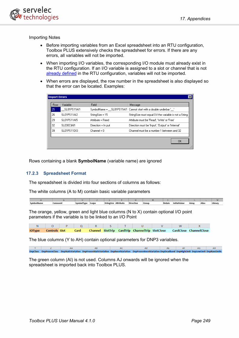
17. Appendices
Toolbox PLUS User Manual 4.1.0 Page 249
Importing Notes
• Before importing variables from an Excel spreadsheet into an RTU configuration, Toolbox PLUS extensively checks the spreadsheet for errors. If there are any errors, all variables will not be imported.
• When importing I/O variables, the corresponding I/O module must already exist in the RTU configuration. If an I/O variable is assigned to a slot or channel that is not already defined in the RTU configuration, variables will not be imported.
• When errors are displayed, the row number in the spreadsheet is also displayed so that the error can be located. Examples:
Rows containing a blank SymbolName (variable name) are ignored
17.2.3 Spreadsheet Format
The spreadsheet is divided into four sections of columns as follows:
The white columns (A to M) contain basic variable parameters
The orange, yellow, green and light blue columns (N to X) contain optional I/O point parameters if the variable is to be linked to an I/O Point
The blue columns (Y to AH) contain optional parameters for DNP3 variables.
The green column (AI) is not used. Columns AJ onwards will be ignored when the spreadsheet is imported back into Toolbox PLUS.

17. Appendices
Toolbox PLUS User Manual 4.1.0 Page 250
17.2.4 Spreadsheet Parameters
Parameter Description Notes SymbolName The variable name See Variable Names. Any rows with
blank SymbolName will be ignored on import.
Comment A comment for the variable Max 128 characters SymbolType The data type Must be a valid type name, see
ISaGRAF Variable Types Scope Describes where this variable is
available for use The text must be either: The word Global, which indicates that the variable can be used in all Functions, Function Blocks and Programs, or the name of a specific Function, Function Block or Program that the Variable can only be used in
StringSize The maximum number of characters in a String variable
If the variable is not a String, the value must be 0
Attribute A Read Only, Write Only or Read and Write variable
Must be: Read, Write or Free (read and write)
Direction Describes the flow of I/O data If this is not attached to an I/O Point, the value must be Internal. Otherwise, the value must be Input or Output
Group The dictionary Group Max 128 characters. If the Group does not already exist, a new Group will be created.
Retain Retain variable value after a reboot
Set Retain to 1 to retain the variable value after a reboot of the RTU. Otherwise set to 0.
InitialValue An initial value for the variable The format of InitialValue depends on its SymbolType. Array values are entered as values separated by commas – example: 2, 3, 4. Strings are entered as text in single quotations – example: ‘This is a string’
Array Array variables Allows multidimensional arrays to be specified
Alias not used Library ISaGRAF Library Allows reference to ISaGRAF library
variables IOType The type of I/O Point For I/O points, must be: AI, AO, DI, or
DO, blank if not an I/O point Controls Output control bits DNP3 binary output control settings
(bitmask), or -1 if not DNPBO variable Slot The slot of the I/O Point module 1-64, or -1 if not an I/O point Card The number of the Option Card
on the Module 1 for I/O point, -1 for other variable
Channel The I/O channel number For I/O points, channel number within I/O module, -1 if not an I/O point
SlotTrip Selects I/O point to perform ‘trip’ Only for DNPBO variables configured for

17. Appendices
Toolbox PLUS User Manual 4.1.0 Page 251
CardTrip operation paired (trip/close) operation.
ChannelTrip SlotClose Selects I/O point to perform
‘close’ operation Only for DNPBO variables configured for paired (trip/close) operation. CardClose
ChannelClose DnpClass The Class of the DNP variable 0-3, or -1 if not a DNP variable DnpFrozenClass Frozen Class 0-3, or -1 if not a DNP variable DnpStaticVariation Static Variation 1-6 (depending on type), or -1 if not a
DNP variable. DnpFrozen-StaticVariation
Frozen Static Variation 1, 2, 5, 6, 9, 10, or -1 if not a DNPBC variable
DnpEventVariation Event Variation 1-7 (depending on type), or -1 if not a DNP variable.
DnpFrozen-EventVariation
Frozen Event Variation 1, 2, 5, 6, or -1 if not a DNPBC variable
DnpDeadband The change in value required to trigger an Event
Either a percentage value or a raw value depending on setting of DnpRawLimits
DnpHighLimit Highest value allowed for this variable
DnpLowLimit Lowest value allowed for this variable
DnpRawLimits Percentage or Raw values 0 = Percentage, 1 = Raw. IecGroup not used

17. Appendices
Toolbox PLUS User Manual 4.1.0 Page 252
17.3 Protocol Support This section describes the extent to which certain communication protocols are supported by the RTU.
17.3.1 Modbus Slave
The following table lists the commands that a slave RTU will accept. Unless otherwise noted, these are applicable for Modbus/TCP, Modbus/RTU and Modbus/ASCII protocols.
Code Function Notes 1 Read coils Returns values of MODCn variables 2 Read discrete inputs Returns values of MODDn variables 3 Read holding registers Returns values of MODHn variables 4 Read input registers Returns values of MODIn variables 5 Write single coil Writes to one MODCn variable 6 Write single register Writes to one MODHn variable 8 Diagnostics See below for supported sub-functions 15 Write multiple coils Writes to multiple MODCn variables 16 Write multiple registers Writes to multiple MODHn variables 22 Mask write register Writes to specific bits within a MODHn variable 23 Read/write multiple registers Write to multiple MODHn variables, then read from
multiple MODHn variables
Diagnostic (function code 8) sub-functions are supported as detailed below:
Code Function Notes 0 Echo received data Returns exact copy of request 1 Restart comms Cancels listen-only mode 2 Return diagnostic register Returns 0 3 Change ASCII delimiter Set Modbus/ASCII delimiter (default LF) 4 Force listen only Do not respond to any further messages, except
Restart Comms 10 Clear all stats counters Clears all stats counters 11 Get bus message count Returns RX message count 12 Get bus error count Returns CRC error count 13 Get bus exception count Returns RX message count 14 Get slave message count Returns RX message count 15 Get slave no-response count Returns no-response count 16 Get slave NAK count Returns exception response count 17 Get slave busy count Returns 0 18 Get bus overrun count Returns 0 20 Clear overrun count Clears all stats counters

17. Appendices
Toolbox PLUS User Manual 4.1.0 Page 253
17.3.2 Modbus Master
When the RTU is operating as a Modbus master, the MODBUS function block is used to send requests to a slave device. The supported message function codes are listed in the Supported function codes table. These functions are supported for the Modbus/TCP, Modbus/RTU and Modbus/ASCII protocols.
17.3.3 DNP3 Master and Slave
Refer to the document DNP Device Profile CP-30, available for download from the Servelec Technologies website.

17. Appendices
Toolbox PLUS User Manual 4.1.0 Page 254
17.4 RTU Variables All data in Kingfisher RTUs are stored as named variables. Space is automatically allocated in RTU memory according to the number of variables that are created and the size of each variable. The set of defined variables is called the dictionary.
ISaGRAF programs can use any variables that have been created in the dictionary.
Variables fall into one of three categories:
• Variables which are automatically created when an I/O module is added to the RTU. The following sections describe the variables which are created for each of the various I/O module types.
• Manually created variables which follow a particular naming convention. These variables can be transferred to and from other systems using particular communications protocols.
• Manually created user variables, for holding temporary values and performing calculations.
17.4.1 Kingfisher PLUS Modular RTU I/O Modules
When an I/O module is added to an RTU, variables are automatically created in the dictionary that correspond to each input, output and data register (eg. counter) available from that module.
These variables are named: SLssmmmmttnn, where:
• SL is a fixed prefix (“slot”)
• ss is the slot number (01-64)
• mmmm is the module type, e.g. AI1, DI10
• tt is the type of I/O point, e.g. AI for analog inputs, DO for digital outputs
• nn is the I/O point number (1, 2, 3…)
The following sections list the automatically created variables for each I/O module type.
All I/O variables have either IOPOINT_B (for digital inputs/outputs) or IOPOINT_D (for analog inputs/outputs and counters) data type.
AI-1 or AI-4
8-channel analog input modules
Data Description Variable Name R/W Notes Analog Input Ch1 SLssAI1AI1 R Raw scale 0-32760 = 0-100% Analog Input Ch2 SLssAI1AI2 R Analog Input Ch3 SLssAI1AI3 R Analog Input Ch4 SLssAI1AI4 R Analog Input Ch5 SLssAI1AI5 R Analog Input Ch6 SLssAI1AI6 R Analog Input Ch7 SLssAI1AI7 R

17. Appendices
Toolbox PLUS User Manual 4.1.0 Page 255
Analog Input Ch8 SLssAI1AI8 R
AI-10
8 channel bipolar analog input module with over range flags
Data Description Variable Name R/W Notes Analog Input Ch1 SLssAI10AI1 R Raw scale: -32768 to +32767
Analog Input Ch2 SLssAI10AI2 R Analog Input Ch3 SLssAI10AI3 R Analog Input Ch4 SLssAI10AI4 R Analog Input Ch5 SLssAI10AI5 R Analog Input Ch6 SLssAI10AI6 R Analog Input Ch7 SLssAI10AI7 R Analog Input Ch8 SLssAI10AI8 R Ch1 Under Range Flag SLssAI10DI1 R Set to TRUE when input current or
voltage is below the minimum value. Ch2 Under Range Flag SLssAI10DI2 R Ch3 Under Range Flag SLssAI10DI3 R Ch4 Under Range Flag SLssAI10DI4 R Ch5 Under Range Flag SLssAI10DI5 R Ch6 Under Range Flag SLssAI10DI6 R Ch7 Under Range Flag SLssAI10DI7 R Ch8 Under Range Flag SLssAI10DI8 R Ch1 Over Range Flag SLssAI10DI9 R Set to TRUE when input current or
voltage is above the maximum value. Ch2 Over Range Flag SLssAI10DI10 R Ch3 Over Range Flag SLssAI10DI11 R Ch4 Over Range Flag SLssAI10DI12 R Ch5 Over Range Flag SLssAI10DI13 R Ch6 Over Range Flag SLssAI10DI14 R Ch7 Over Range Flag SLssAI10DI15 R Ch8 Over Range Flag SLssAI10DI16 R
AO-2
4 channel analog output module
Data Description Variable Name R/W Notes Analog Output Ch1 SLssAO2AO1 R/W Raw scale 0-32760 = 0-100% Analog Output Ch2 SLssAO2AO2 R/W Analog Output Ch3 SLssAO2AO3 R/W Analog Output Ch4 SLssAO2AO4 R/W

17. Appendices
Toolbox PLUS User Manual 4.1.0 Page 256
AO-3
4 channel analog output module with open loop detection
Data Description Variable Name R/W Notes Analog Output Ch1 SLssAO3AO1 R/W Raw scale 0-32760 = 0-100% Analog Output Ch2 SLssAO3AO2 R/W Analog Output Ch3 SLssAO3AO3 R/W Analog Output Ch4 SLssAO3AO4 R/W Ch1 Open Loop SLssAO3DI1 R 1 = Open Loop Ch2 Open Loop SLssAO3DI2 R Ch3 Open Loop SLssAO3DI3 R Ch4 Open Loop SLssAO3DI4 R
DI-1
16 channel digital input module
Data Description Variable Name R/W Notes Digital Input Ch1 SLssDI1DI1 R Digital Input Ch2 SLssDI1DI2 R Digital Input Ch3 SLssDI1DI3 R Digital Input Ch4 SLssDI1DI4 R Digital Input Ch5 SLssDI1DI5 R Digital Input Ch6 SLssDI1DI6 R Digital Input Ch7 SLssDI1DI7 R Digital Input Ch8 SLssDI1DI8 R Digital Input Ch9 SLssDI1DI9 R Digital Input Ch10 SLssDI1DI10 R Digital Input Ch11 SLssDI1DI11 R Digital Input Ch12 SLssDI1DI12 R Digital Input Ch13 SLssDI1DI13 R Digital Input Ch14 SLssDI1DI14 R Digital Input Ch15 SLssDI1DI15 R Digital Input Ch16 SLssDI1DI16 R

17. Appendices
Toolbox PLUS User Manual 4.1.0 Page 257
DI-5
16 channel digital input / 4 counter module
Data Description Variable Name R/W Notes Digital Input Ch1 SLssDI5DI1 R The first 4 channels interface to hardware
counters. Channels 1 and 2 up to 10kHz. Channels 3 & 4 up to 255Hz. If the maximum pulse rate is exceeded on channels 3 and 4 (>255 Hz), each counter will contain the lowest 8 bits of the actual pulse rate. Results are unpredictable at pulse rates greater than 1 kHz
Digital Input Ch2 SLssDI5DI2 R Digital Input Ch3 SLssDI5DI3 R Digital Input Ch4 SLssDI5DI4 R Digital Input Ch5 SLssDI5DI5 R Digital Input Ch6 SLssDI5DI6 R Digital Input Ch7 SLssDI5DI7 R Digital Input Ch8 SLssDI5DI8 R Digital Input Ch9 SLssDI5DI9 R Digital Input Ch10 SLssDI5DI10 R Digital Input Ch11 SLssDI5DI11 R Digital Input Ch12 SLssDI5DI12 R Digital Input Ch13 SLssDI5DI13 R Digital Input Ch14 SLssDI5DI14 R Digital Input Ch15 SLssDI5DI15 R Digital Input Ch16 SLssDI5DI16 R Ch1 Total Pulses SLssDI5AI1 R/W Ch2 Total Pulses SLssDI5AI2 R/W Ch3 Total Pulses SLssDI5AI3 R/W Ch4 Total Pulses SLssDI5AI4 R/W Ch1 Pulse Rate Hz SLssDI5AI5 R/W Ch2 Pulse Rate Hz SLssDI5AI6 R/W Ch3 Pulse Rate Hz SLssDI5AI7 R/W Ch4 Pulse Rate Hz SLssDI5AI8 R/W

17. Appendices
Toolbox PLUS User Manual 4.1.0 Page 258
DI-10
16 channel digital input / 7 counter module with event time-stamping
Data Description Variable Name R/W Notes Digital Input Ch1 SLssDI10DI1 R Has configurable Frequency or Pulse or
Quadrature counting and Sequence-of-Events recording (using event logs). Counters 1-7 can count Frequency (0-10kHz max.) or Total Pulses (0-65535) or Quadrature Count (0-65535) for any configured channel(s) (as configured using Toolbox PLUS)
Digital Input Ch2 SLssDI10DI2 R Digital Input Ch3 SLssDI10DI3 R Digital Input Ch4 SLssDI10DI4 R Digital Input Ch5 SLssDI10DI5 R Digital Input Ch6 SLssDI10DI6 R Digital Input Ch7 SLssDI10DI7 R Digital Input Ch8 SLssDI10DI8 R Digital Input Ch9 SLssDI10DI9 R Digital Input Ch10 SLssDI10DI10 R Digital Input Ch11 SLssDI10DI11 R Digital Input Ch12 SLssDI10DI12 R Digital Input Ch13 SLssDI10DI13 R Digital Input Ch14 SLssDI10DI14 R Digital Input Ch15 SLssDI10DI15 R Digital Input Ch16 SLssDI10DI16 R Counter 1 SLssDI10AI1 R/W Counter 2 SLssDI10AI2 R/W Counter 3 SLssDI10AI3 R/W Counter 4 SLssDI10AI4 R/W Counter 5 SLssDI10AI5 R/W Counter 6 SLssDI10AI6 R/W Counter 7 SLssDI10AI7 R/W
DO-1
8 channel digital output module
Data Description Variable Name R/W Notes Digital Output Ch1 SLssDO1DO1 R/W Digital Output Ch2 SLssDO1DO2 R/W Digital Output Ch3 SLssDO1DO3 R/W Digital Output Ch4 SLssDO1DO4 R/W Digital Output Ch5 SLssDO1DO5 R/W Digital Output Ch6 SLssDO1DO6 R/W Digital Output Ch7 SLssDO1DO7 R/W Digital Output Ch8 SLssDO1DO8 R/W
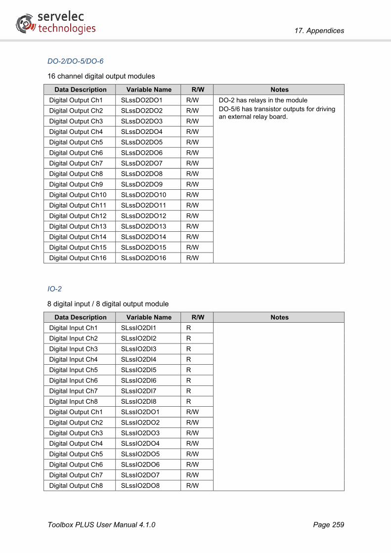
17. Appendices
Toolbox PLUS User Manual 4.1.0 Page 259
DO-2/DO-5/DO-6
16 channel digital output modules
Data Description Variable Name R/W Notes Digital Output Ch1 SLssDO2DO1 R/W DO-2 has relays in the module
DO-5/6 has transistor outputs for driving an external relay board.
Digital Output Ch2 SLssDO2DO2 R/W Digital Output Ch3 SLssDO2DO3 R/W Digital Output Ch4 SLssDO2DO4 R/W Digital Output Ch5 SLssDO2DO5 R/W Digital Output Ch6 SLssDO2DO6 R/W Digital Output Ch7 SLssDO2DO7 R/W Digital Output Ch8 SLssDO2DO8 R/W Digital Output Ch9 SLssDO2DO9 R/W Digital Output Ch10 SLssDO2DO10 R/W Digital Output Ch11 SLssDO2DO11 R/W Digital Output Ch12 SLssDO2DO12 R/W Digital Output Ch13 SLssDO2DO13 R/W Digital Output Ch14 SLssDO2DO14 R/W Digital Output Ch15 SLssDO2DO15 R/W Digital Output Ch16 SLssDO2DO16 R/W
IO-2
8 digital input / 8 digital output module
Data Description Variable Name R/W Notes Digital Input Ch1 SLssIO2DI1 R Digital Input Ch2 SLssIO2DI2 R Digital Input Ch3 SLssIO2DI3 R Digital Input Ch4 SLssIO2DI4 R Digital Input Ch5 SLssIO2DI5 R Digital Input Ch6 SLssIO2DI6 R Digital Input Ch7 SLssIO2DI7 R Digital Input Ch8 SLssIO2DI8 R Digital Output Ch1 SLssIO2DO1 R/W Digital Output Ch2 SLssIO2DO2 R/W Digital Output Ch3 SLssIO2DO3 R/W Digital Output Ch4 SLssIO2DO4 R/W Digital Output Ch5 SLssIO2DO5 R/W Digital Output Ch6 SLssIO2DO6 R/W Digital Output Ch7 SLssIO2DO7 R/W Digital Output Ch8 SLssIO2DO8 R/W

17. Appendices
Toolbox PLUS User Manual 4.1.0 Page 260
IO-3
4 digital input / 4 digital output / 4 analog input / 1 analog output module
Data Description Variable Name R/W Notes Digital Input Ch1 SLssIO3DI1 R Analog raw scale 0-32760 = 0-100% Digital Input Ch2 SLssIO3DI2 R Digital Input Ch3 SLssIO3DI3 R Digital Input Ch4 SLssIO3DI4 R Digital Output Ch1 SLssIO3DO1 R/W Digital Output Ch2 SLssIO3DO2 R/W Digital Output Ch3 SLssIO3DO3 R/W Digital Output Ch4 SLssIO3DO4 R/W Analog Input Ch1 SLssIO3AI1 R Analog Input Ch2 SLssIO3AI2 R Analog Input Ch3 SLssIO3AI3 R Analog Input Ch4 SLssIO3AI4 R Analog Output Ch1 SLssIO3AO1 R/W
IO-4
8 digital input / 2 digital output / 2 analog input module
Data Description Variable Name R/W Notes Digital Input Ch1 SLssIO4DI1 R Analog raw scale 0-32760 = 0-100% Digital Input Ch2 SLssIO4DI2 R Digital Input Ch3 SLssIO4DI3 R Digital Input Ch4 SLssIO4DI4 R Digital Input Ch5 SLssIO4DI5 R Digital Input Ch6 SLssIO4DI6 R Digital Input Ch7 SLssIO4DI7 R Digital Input Ch8 SLssIO4DI8 R Digital Output Ch1 SLssIO4DO1 R/W Digital Output Ch2 SLssIO4DO2 R/W Analog Input Ch1 SLssIO4AI1 R Analog Input Ch2 SLssIO4AI2 R

17. Appendices
Toolbox PLUS User Manual 4.1.0 Page 261
IO-5
4 digital input / 4 digital output / 4 analog input / 4 counter module
Data Description Variable Name R/W Notes Digital Input Ch1 SLssIO5DI1 R Digital Input Ch2 SLssIO5DI2 R Digital Input Ch3 SLssIO5DI3 R Digital Input Ch4 SLssIO5DI4 R Digital Output Ch1 SLssIO5DO1 R/W Digital Output Ch2 SLssIO5DO2 R/W Digital Output Ch3 SLssIO5DO3 R/W Digital Output Ch4 SLssIO5DO4 R/W Analog Input Ch1 SLssIO5AI1 R Analog raw scale 0-32760 = 0-100% Analog Input Ch2 SLssIO5AI2 R Analog Input Ch3 SLssIO5AI3 R Analog Input Ch4 SLssIO5AI4 R Digital Input Counter 1 SLssIO5AI5 R Digital Input Counter 2 SLssIO5AI6 R Digital Input Counter 3 SLssIO5AI7 R Digital Input Counter 4 SLssIO5AI8 R

17. Appendices
Toolbox PLUS User Manual 4.1.0 Page 262
PS-1x or PS-2x
Power supply modules
Data Description Variable Name R/W Notes Supply Voltage SLssPS11AI1 R Raw Scale= 0-32736, Eng. Units=0 to 32.27V
The DC voltage supplied to the RTU modules on the backplane (typically 12V) and used to charge the battery. This voltage is sourced from the battery if there is no input supply present.
Battery Current SLssPS11AI2 R Raw Scale=-32768 to 32736 (+4..+8,-8..+4 A) Amps = ((raw+16400) mod 65536) * 16/65536 – 8 Positive = battery charging, negative = discharging
Total Current SLssPS11AI3 R Raw Scale=-32768 to 32736 (+4..+8,-8..+4 A) Amps = ((raw+16400) mod 65536) * 16/65536 – 8 Total current supplied by the power supply to the RTU modules and battery (always positive).
Battery Temperature
SLssPS11AI4 R Raw Scale=-32768 to 32736 (+80..+140,-60..+80 °C) °C = ((raw+13104) mod 65536) * 200/65536 – 60
Battery Type SLssPS11AI5 R 0 = Default, 1 = Lead-Acid, 2 = Ni-Cad Battery Size SLssPS11AI6 R Battery Size (x 0.1AH) 0 to 250 = 0 to 25.0 AH Max. Module Temperature
SLssPS11AI7 R Raw Scale=-32768 to 32736 (+80..+140,-60..+80 °C) °C = ((raw+13104) mod 65536) * 200/65536 - 60
Power ON SLssPS11DI1 R 1 = AC (PS-1x) or DC (PS-2x) Power ON AUX 24V Fail SLssPS11DI2 R 1 = Auxiliary 24V failure or not present Battery Low SLssPS11DI3 R 0 = Battery low. Note: Active low.
This bit does not indicate if a battery is present as Battery Low is cleared whenever the input supply is active. If the input supply is OFF (ie. SLssPS11DI1=0), a battery is present if the RTU is still running!
Power Supply Type SLssPS11DI4 R 1 = PS-2x, 0 = PS-1x Float State SLssPS11DI5 R 1 = float state Charge State SLssPS11DI6 R 1 = charge state Boost State SLssPS11DI7 R 1 = boost state Temperature Sensor Error
SLssPS11DI8 R 1 = sensor error
Manual Power Control
SLssPS11DO1 R/W 0 = automatic control (default) 1 = manual control. Allows manual control of Radio and 24V power (and Mains Supply for PS-1x)
Radio power OFF SLssPS11DO2 R/W 1 = radio OFF (if SLssPS11DO1=1) Aux 24V OFF SLssPS11DO3 R/W 1 = 24V OFF (if SLssPS11DO1=1) Inhibit AC Supply Input Circuit (PS-1x only)
SLssPS11DO4 R/W 1 = inhibit AC (if SLssPS11DO1=1)
17.4.2 Kingfisher Register Variables
Kingfisher local register variables are used to store 16-bit data values to be transferred between RTUs using the Kingfisher, Allen Bradley DF1 or HART protocols.

17. Appendices
Toolbox PLUS User Manual 4.1.0 Page 263
Variables must be manually created in the Dictionary before they can be used in logic or transferred via a protocol.
Kingfisher register variable names have the format: KFrRn, where
• r is the address of the RTU from which the variable originated. If the variable belongs to the local RTU then this is blank.
• n is the register number (1-2048)
Floating point Kingfisher registers (type REAL) may also be created, which are named KFrFn. These are only supported by the HART protocol, however.
In summary:
Variable Name Type Description KFrRn DINT Kingfisher integer register #n on RTU r KFrFn REAL Kingfisher floating point register #n on RTU r
For example, local Kingfisher register #315 would be named KFR315, while register #210 retrieved from RTU 17 would be KF17R210.
17.4.3 Modbus Variables
Modbus variables are used to store 1-bit or 16-bit data values to be transferred between RTUs using the Modbus protocol.
Variables must be manually created in the Dictionary before they can be used in logic or transferred via Modbus.
Modbus variable names have the format: MODrTn, where
• r is the address of the RTU from which the variable originated. If the variable belongs to the local RTU then this is blank.
• T is the type of Modbus variable (see below)
• n is the register number (1-65535)
The following variable types may be created:
Variable Name Type Description MODrCn BOOL Modbus coil #n on RTU r MODrDn BOOL Modbus discrete input #n on RTU r MODrHn DINT Modbus holding register #n on RTU r MODrIn DINT Modbus input register #n on RTU r
For example, the variable for Modbus coil #22 on the local RTU would be named MODC22, while Modbus input register #2 read from RTU 39 would be MOD39I2.
Note that only the least significant byte of the RTU address (r) will be used in Modbus messages. This means that two RTUs whose addresses have the same least significant byte (e.g. addresses 3 and 259) cannot be connected on the same network if Modbus is to be used.
Note also that some device documentation or SCADA systems identify the type of Modbus point by adding a numeric prefix, e.g. holding registers are in the range 40001-49999 or

17. Appendices
Toolbox PLUS User Manual 4.1.0 Page 264
400001-465535. The point number (n) specified in the variable name should not include this prefix digit, e.g. point 40006 would correspond to variable MODH6.
17.4.4 DNP3 Variables
DNP3 variables are used to store data values to be transferred between RTUs using the DNP3 protocol.
Variables must be manually created in the Dictionary before they can be used in logic or transferred via Modbus.
DNP3 variable names have the format: DNPrTn, where
• r is the address of the RTU from which the variable originated. If the variable belongs to the local RTU then this is blank.
• T is the type of DNP3 variable (see below)
• n is the register number (0-65535)
The following variable types may be created:
Variable Name Type Description DNPrBIn IOPOINT_B Binary input #n on RTU r DNPrBOn IOPOINT_B Binary output #n on RTU r DNPrBCn IOPOINT_D Binary counter #n on RTU r DNPrFCn IOPOINT_D Frozen counter #n on RTU r DNPrAIn IOPOINT_D or
IOPOINT_R Analog input #n on RTU r
DNPrAOn IOPOINT_D or IOPOINT_R
Analog output #n on RTU r
For example, the variable for DNP3 binary input #0 on the local RTU would be named DNPBI0, while DNP3 analog input #21 read from RTU 909 would be DNP909AI21.
DNP3 variables use the IOPOINT_x structure types, which include timestamp and flag information as well as the actual data value.

17. Appendices
Toolbox PLUS User Manual 4.1.0 Page 265
17.4.5 DNP3 Internal Indication Register
The DNP3 protocol defines a 16-bit Internal Indication (IIN) register, which is used to return status information as part of every response message sent by a slave device.
For reference, the IIN bit definitions are shown below:
Bit Name Notes 15 (IIN1.7) DEVICE_RESTART Set ON following an RTU restart 14 (IIN1.6) DEVICE_TROUBLE Not set by RTU 13 (IIN1.5) LOCAL_CONTROL Not set by RTU 12 (IIN1.4) NEED_TIME Set ON when time synchronisation is required from the
master. The bit is cleared when the master sets the time. 11 (IIN1.3) CLASS_3_EVENTS Set ON when the RTU has one or more Class 3 events to
report. Once all points of the class have been read by the master, the bit will be reset.
10 (IIN1.2) CLASS_2_EVENTS Similarly for Class 2 events. 9 (IIN1.1) CLASS_1_EVENTS Similarly for Class 1 events. 8 (IIN1.0) ALL_STATIONS Set ON when an all stations (broadcast) message is
received 7 (IIN2.7) Reserved Not set by RTU 6 (IIN2.6) Reserved Not set by RTU 5 (IIN2.5) CONFIG_CORRUPT Not set by RTU 4 (IIN2.4) ALREADY_EXECUTING Not set by RTU 3 (IIN2.3) EVENT_BUFFER_OVERFLOW Set ON if the oldest un-read event has been overwritten 2 (IIN2.2) PARAMETER_ERROR Set ON if a requested parameter is invalid or out of range 1 (IIN2.1) OBJECT_UNKNOWN Set ON If the requested object is not found by the driver 0 (IIN2.0) NO_FUNC_CODE_SUPPORT Set ON if the requested function code is not implemented

17. Appendices
17.4.6 Further Information:
Support website: (registration required) http://helpdesk.servelec-semaphore.com/
Contact us directly: http://www.servelec-group.com/technologies/support/