for inland vessels user manual - alphatron marineam...abbreviation explanation ecdis electronic...
TRANSCRIPT

AlphaRiverTrackPilotfor inland vessels
User Manual
www.jrc.am

Contents
I Preface..........................................................................................................3I.1 Revision History........................................................................................................................................................ 3I.2 Abbreviations.............................................................................................................................................................3
II Safety Instructions..................................................................................... 4
1 Description.................................................................................................. 51.1 Limitations................................................................................................................................................................ 5
2 System Overview........................................................................................62.1 Scope of Delivery.....................................................................................................................................................62.2 Technical Data......................................................................................................................................................... 7
3 Operation.....................................................................................................83.1 Touchscreen Interface..............................................................................................................................................8
3.1.1 Track Pilot....................................................................................................................................................... 93.1.2 Menu..............................................................................................................................................................103.1.3 Profiles...........................................................................................................................................................103.1.4 Version.......................................................................................................................................................... 113.1.5 Configuration................................................................................................................................................. 113.1.6 ROT............................................................................................................................................................... 12
3.2 Switching Track Control On...................................................................................................................................123.3 Switching Track Control Off...................................................................................................................................143.4 Adjusting the Offset............................................................................................................................................... 14
4 System Warnings and Errors..................................................................154.1 Alarms.................................................................................................................................................................... 154.2 Warnings................................................................................................................................................................ 17
5 Appendix................................................................................................... 20
2 | Contents

I Preface
I.1 Revision History
Revision Description Author Date
V1.0 First release 1 - October - 2018
V1.1 Added drawing 27 - March - 2019
I.2 Abbreviations
Abbreviation Explanation
ECDIS Electronic Chart Display Information System
GPS Global Positioning System
IP rating International Protection rating
LED Light-Emitting Diode
LTE Long Term Evolution
PLC Program Logic Controller
Vdc Volt direct current
NMEA National Marine Electronics Association
GGA NMEA sentence: Global Positioning System Fix Data
HDT NMEA sentence: Heading Degrees, True
ROT NMEA sentence: Rate Of Turn
VTG NMEA sentence: Track Made Good and Ground Speed
Table 1: List of Abbreviations
3 | Preface

II Safety InstructionsThis manual applies only to the track control system AlphaRiverTrackPilot. It does not apply to the autopilot system (ROTcontrol), the ROT sensor and indicator, the GPS receiver nor the rudder control system. For a safe operation of the trackcontrol system the following safety instructions must be respected:
• Read the complete manual before activating the track control system.
• Keep this manual at hand for all users of the track control system.
• Maintenance and installation must only be carried out by qualified persons.
• Risk of electric shock or physical damage! Always disconnect power to the track control system before performingany maintenance. Make sure the track control system can not be switched on accidentally.
• Follow the local rules concerning accident prevention and environmental protection.
• Follow the general safety instructions of the country where the track control system is used.
• Make sure the track control system is only used when in perfect technical condition.
• The skipper must monitor the operation of the track control system at any time and switch back to manual control incase of an error.
• The track control system has only one sensor for determining the position and orientation of the ship (GPS compass).If there is an undetected failure of the sensor there may be large deviations from the selected track. Especiallybeneath bridges and close to large buildings, reception of GPS signals is deteriorated, and thus the track controlsystem must be monitored carefully.
• There is no warranty that the tracks delivered with the track control system are free of errors.
• The track control system is not an autonomous system that reacts to the surrounding traffic. The skipper is fullyresponsible to comply with the laws and regulations of inland navigation.
• At the beginning of each trip, the skipper must make sure that switching between track control, autopilot andemergency steering works correctly.
• If an alarm is signaled by the track control system, switch over to manual or emergency steering. Once the alarm isresolved, the track control system can be activated again.
4 | Safety Instructions

1 DescriptionAlphaRiverTrackPilot is a track control system for inland vessels. It is designed to assist in navigation by steering theship along pre-defined guiding lines. The track control system computes the steering commands such that the center ofgravity of the ship follows the guiding line with a small cross track error. The steering commands are sent to the autopilotsystem as values for desired rate of turn (ROT). The autopilot system controls the rudder angle so that the ship turnsas required by the track control system. The position, orientation and motion of the ship are measured using a GPScompass together with a ROT sensor (gyro).
Figure 1: Overview navigation
The track control system features a network interface for inland ECDIS chart displays. At first, the chart display showsthe selected guiding line. Later, using the chart system, it is possible to select other guiding lines or create new guidinglines according to personal experience and send them to the track control system.
For passing and encounter of other vessels there is an adjustable offset to the guiding line. The offset is changed usingthe joystick on the control panel, a button on the touchscreen serves to reset the offset to zero. When an offset has beenset, a new parallel guiding line is computed by the track control system and displayed, in red, in the chart system.
The track control system is delivered together with a touchscreen that displays the most important data of the controlsystem. It is possible to select different configurations and control parameters i.e. for different loading conditions. Thetouchscreen also displays alarms and warnings.
The track control system can be delivered with an optional LTE modem for remote monitoring and maintenance.
1.1 LimitationsThe track control system performs an extensive analysis of the sensor data to be able to detect errors of the GPSreceiver and the ROT sensor. The detection of errors is subject to the technical possibilities. Detected errors aredisplayed on the touchscreen. Severe errors will trigger an additional acoustic alarm. In case of such a severe error, it isrequired to switch to manual steering.
Since there is only one single sensor for the measurement of the position and attitude of the ship, there is no guaranteethat every possible error of the sensor is detected. If there is an undetected failure of the sensor there may be largedeviations from the selected track. Especially beneath bridges and close to large buildings, reception of GPS signals isdeteriorated and thus the track control system must be monitored carefully. Someone must monitor the operation of thetrack control system at any time and switch back to manual control in case of an error. The track control system is not anautonomous system that reacts to the surrounding traffic.
The skipper is fully responsible to comply with the laws and regulations of inland navigation.
5 | Description

2 System OverviewThe following diagram shows a functional overview of the AlphaRiverTrackPilot system for inland vessels.
Figure 2: Functional drawing of the AlphaRiverTrackPilot
The individual parts are:
1. LTE modem
2. AlphaRiverTrackPilot panel
3. PLC
4. ROT sensor
5. Autopilot
6. GPS compass
7. ECDIS chart display
2.1 Scope of DeliveryThe delivery of the AlphaRiverTrackPilot comprises of:
• Control cabinet with AlphaRiverTrackPilot
• Control panel with joystick and touchscreen 7" for table top mounting
• Optional: LTE modem
6 | System Overview
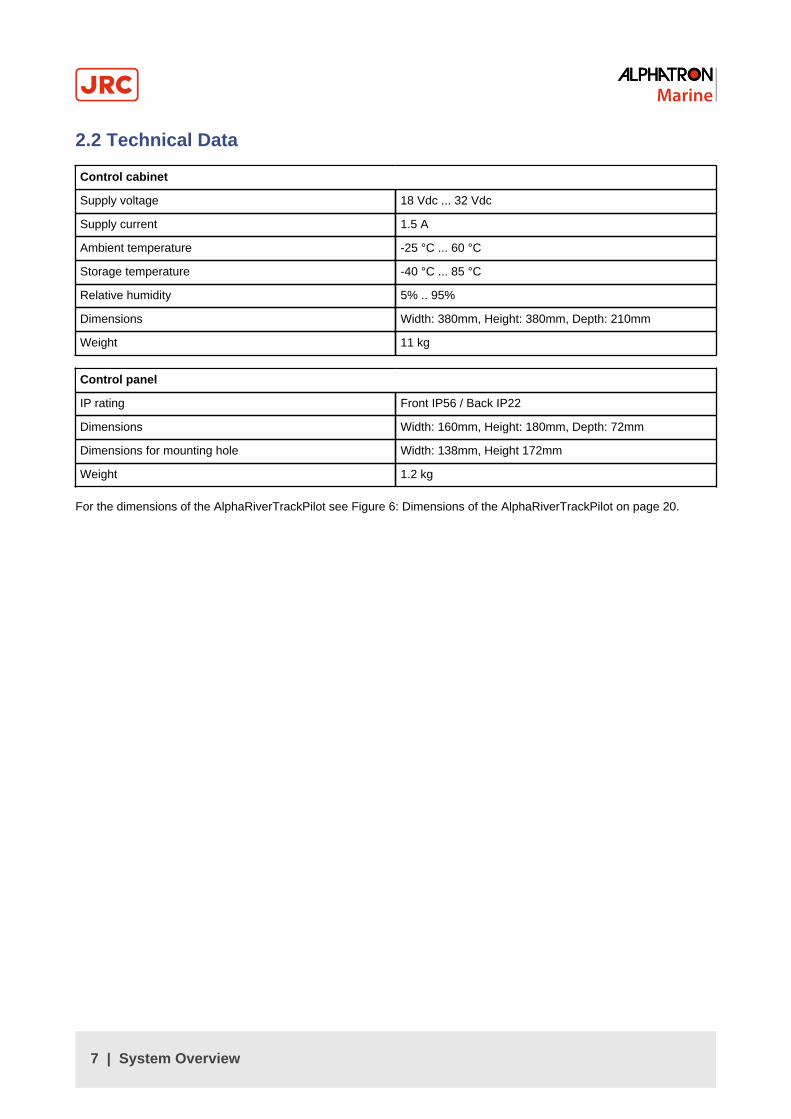
2.2 Technical Data
Control cabinet
Supply voltage 18 Vdc ... 32 Vdc
Supply current 1.5 A
Ambient temperature -25 °C ... 60 °C
Storage temperature -40 °C ... 85 °C
Relative humidity 5% .. 95%
Dimensions Width: 380mm, Height: 380mm, Depth: 210mm
Weight 11 kg
Control panel
IP rating Front IP56 / Back IP22
Dimensions Width: 160mm, Height: 180mm, Depth: 72mm
Dimensions for mounting hole Width: 138mm, Height 172mm
Weight 1.2 kg
For the dimensions of the AlphaRiverTrackPilot see Figure 6: Dimensions of the AlphaRiverTrackPilot on page 20.
7 | System Overview

3 OperationThe touchscreen of the control panel shows the most important data of the control system. Via the touchscreen it ispossible to adjust and reset the offset to the guiding line, and select different configurations and control parameters fordifferent loading conditions. The touchscreen also displays detailed alarm and warning information.
3.1 Touchscreen InterfaceThe following figure shows the structure of the touchscreen interface. The default page is the "Track Pilot" page (lowerleft). Using the "PROFILES" button the configuration selection page for different loading conditions is reached (topleft). By pressing "MENU", the central selection page is shown. From here, the "ROT" page (right), the "CONFIG" page(bottom) and the "ABOUT" page (top right) can be reached. The "ROT" page shows the current and desired value of theturning rate. The "CONFIG" page shows important configuration parameters of the track keeping system. The "ABOUT"page displays information about the version of the user interface and the track control software. The following chaptersgive detailed information about each of the pages of the touchscreen interface control.
Figure 3: Pages on touchscreen interface
8 | Operation

3.1.1 Track PilotThe Page "Track Pilot" shows the most important information concerning the track control system:
1. Current offset (Distance between original guiding line and parallel line): The blue line at 0 m offset corresponds to theoriginal guiding line. The red label displays the current offset. If the red label is to the left of the blue line, the ship willmove at the desired offset to the port side of the original line, and vice versa.
2. Current cross track error in relation to the desired offset. The figure shows a cross track error of 6.3m to the portside of the parallel line.
3. Adjust port: Move parallel line to the port side.
4. Reset offset: Move parallel line to the original line.
5. Adjust to current offset: Move parallel line to the current position.
6. Adjust starboard: Move parallel line to starboard side.
7. Run: A green led light shows the state (ON) of the track control system.
8. ROT command to autopilot system in °/min.
9. ROT of the ship in °/min. To achieve good performance of the track control system it is important that the autopilotsystem is able to follow the ROT command without much delay and without overshoot.
10. Filter: State of the position estimation system. Track control can not be switched on if state is not OK (red light). If thetrack control system is already switched on, and an error occurs, the "Filter" light turns red. This can happen whenpassing bridges and the GPS signal is lost. Short losses of GPS signal are compensated by dead reckoning and arenot a problem. If the signal is lost for a longer time, an alarm will be activated.
11. Track: State of the current guiding line. Track control can not be switched on if state is not Ok. If the track controlsystem is already switched on and an error is detected, the "Track" light turns red and an alarm is activated. Thesystem checks if the guiding line in front of the ship is long enough and if there are very sharp turns.
12. Alarm area: Alarms and warnings are signaled in this area (see Alarms on page 15).To show the alarmdescription, press the alarm symbol. Alarms are shown with red color, warnings are shown with yellow color. Alarmscan only be acknowledged and reset by switching off track control. To acknowledge a warning, press and hold thewarning symbol. The warning symbol changes to an exclamation mark if the warning has been acknowledged.
13. CONFIG: Directly open configuration page. see Configuration on page 11.
PROFILES: Directly open profiles page. See Profiles on page 10.
9 | Operation

3.1.2 MenuPressing the MENU-Button, in the bottom left corner of the screen, on any page, will change the page to the "Menu"page. On the "Menu" page there is a selection menu for the different pages of the control panel.
3.1.3 ProfilesOn the page "Profiles" different sets of controller parameters can be selected for different loading conditions. Theseparameter sets have to be activated and adjusted by a qualified technician during a sea-trial. The active parameters setis highlighted by a blue bar.
10 | Operation

3.1.4 VersionThe "ABOUT" page displays information about the version of the user interface and the track control software.
3.1.5 ConfigurationThe page "CONFIGURATION" contains important settings for the track control system that does have a direct impact onthe performance of the track control system. It is important to adjust the correct settings for a good control performance.
• CONTROLLER GAIN: The controller gain can be adjusted from "LOW" to "HIGH". A higher controller gain allowsfor more rudder activity and leads to a smaller cross track error. Increased rudder activity can lead to less smoothsteering of the ship. This gain is similar to the rudder setting of an autopilot. The button "+" and "-" can be used forfine tuning of the controller gain.
• CURRENT SPEED: With this setting the control system is able to compensate for the effects of the river current.This setting is especially important for a good performance of the control system in turns because it determines thedesired drift angle. For this reason it is needed to estimate the speed of the current and select the correspondingsetting. Two arrows correspond to +/- 6 km/h current, one arrow corresponds to +/-3 km/h. The arrows on the left side(down) must be selected when the ship sails in opposite direction of the current, the arrows on the right (up) must beselected if the ship sails in the same direction as the current.
• MAIN: By pressing the button "MAIN", the page "Track Pilot" will be displayed again.
11 | Operation

3.1.6 ROTThe page "ROT" shows the current value of ROT in °/min. Also on this page is displayed the command value of the trackcontrol system to the autopilot system (red triangle, red numbers).
3.2 Switching Track Control OnThere are two possibilities how the track control system is switched on:
• Alphatron autopilot: Select "Compass" on the autopilot control panel.
• Veth brand autopilot: Press "Track" on the touchscreen of the AlphaRiverTrackPilot control panel.
The following conditions must be satisfied before the track control system can be switched on:
• Filter is OK (led is green)
• Track is OK (led is green)
• Autopilot system is ready to enter track pilot mode
When the track control system is active, the light "Run" on the touchscreen is green. On other autopilots the button"Track" on the touchscreen is highlighted with a blue bar.
Following there ares some examples of the Track pilot:
• Alphatron autopilot:
• Veth autopilot:
12 | Operation

• Warning
• The user must check if the track control system is active and working correctly, otherwise the user needs tocontinue to steer manually. Before switching on the track control system, the user must check in the chartdisplay if the displayed ship position and orientation match the real position and orientation. Additionally, theuser must check if the selected guiding line is on the fairway, and free of collisions.
The track control system checks the following conditions before the light "Filter" and "Track" is green:
• The GPS system transmits position and heading information
• The position and heading information received from the GPS system are consistent
• The selected guiding line is free from kinks and loops
• The selected guiding line is long enough
• The distance to the selected guiding line is not too large
The track control system can not be switched on if the filter and the track are not OK. If one of the above conditions isnot met during active track control, the state of the light for "Filter" or "Track" will change into red color. An acoustic andoptical alarm will be activated that can only be reset by switching the track control off. For more information about alarmssee Alarms on page 15.
13 | Operation

3.3 Switching Track Control OffTo switch the track control system off:
• Select "AUTO" or "WEG" on the autopilot control panel.
• Press "Track" on the touchscreen of the AlphaRiverTrackPilot control panel
If the track control system has been switched off successfully the green light "Run" on the touchscreen changes into red.For other autopilots, the blue bar on the "Track" button on the touchscreen disappears. It is needed to check if the trackcontrol system is really switched off and the manual steering is functioning as expected.
3.4 Adjusting the OffsetFor passing and meeting of other vessels there is an adjustable offset to the guiding line. To adjust the offset movethe joystick on the control panel left or right. The speed of the adjustment is proportional to the angle of the joystick.The offset can also be adjusted by pressing the corresponding buttons on the touchscreen of the control panel (seeTouchscreen Interface on page 8). To reset the offset to the original line use the button on the touchscreen.
The position of the new parallel line must be checked in the chart display to make sure that the new line is inside thefairway and does not lead to collisions. The following left picture shows the original guiding line (blue) and the newparallel line (red) with an offset to starboard. On the right picture, the original guiding line (blue) and the new parallel line(red) are shown after resetting the offset to zero.
Figure 4: Offset to Starboard Figure 5: After reset of offset
14 | Operation

4 System Warnings and Errors
4.1 AlarmsAlarms are raised in critical situations and require an immediate reaction of the skipper. Alarms are signaled using anacoustic and optical signal. The optical signal is a blinking red symbol in the top left alarm area of the touchscreen. Bypressing the alarm symbol, more information will be displayed in the bottom area of the screen. If there is more than oneactive alarms, the alarm text in the bottom area will switch between the different alarms.
Note Alarms can only be reset, by turning off the track control.
The following table lists all possible alarms and give some advice on how to react on a certain alarm.
Name Description Action
MaxROTChangeExceeded Fast change in ROT command toautopilot. The command has notbeen sent to the autopilot to preventa dangerous maneuver. Could becaused by an undetected error of theGPS sensor.
• Acknowledge alarm by switchingto manual steering.
Note There is no otherway to acknowledge thealarm.
Note Track controlsystem can not beswitched on until problemis fixed.
• Wait until state of "Filter" led lightreturns to green color.
• Check in chart display if the ship'sposition on the map and realitymatch.
• Switch on track control system.
• Increased attention.
• If the problem returns, switch tomanual steering.
VeryCloseToEndOfGuidingline The ship is very close to the endof the guiding line. After reachingthe end the track control systemcannot compute meaningful commandvalues.
• Immediately switch to manualsteering.
• Choose new guiding line.
15 | System Warnings and Errors

Name Description Action
CurvatureError Guiding line check returned acurvature value that would lead to ahigh turning rate. Caused by an errorin the guiding line, either way pointsare too close together, not alignedcorrectly, or the track contains a verysharp bend.
• Acknowledge alarm by switchingto manual steering.
Note There is no otherway to acknowledge thealarm.
Note Track controlsystem can not beswitched on until problemis fixed.
• Check the guiding line displayed inthe chart display. Look for kinks orloops.
• Correct bad way points.
• Activate other guiding line.
• Wait until state of "Track"led lightreturns to green color.
• Switch on track control system.
• Increased attention.
CurvatureDerivativeError Guiding line check returned acurvature derivative value that wouldlead to a high turning rate change.Caused by an error in the guidingline, either way points are too closetogether, not aligned correctly, or thetrack contains a very sharp bend.
• Acknowledge alarm by switchingto manual steering.
Note There is no otherway to acknowledge thealarm.
Note Track controlsystem can not beswitched on until problemis fixed.
• Check the guiding line displayed inthe chart display. Look for kinks orloops.
• Correct bad way points.
• Activate other guiding line.
• Wait until state of "Track" led lightreturns to green color.
• Switch on track control system.
• Increased attention.
16 | System Warnings and Errors

Name Description Action
DistanceWarning The distance to the selected guidingline is too large. This error can occurif the wrong guiding line (wrong riverfor example) is selected in the chartsystem. Also after reboot of the trackcontrol system, a default guiding lineis selected that is not close enoughto the current position. Or the desiredoffset from the guiding line is toolarge.
• Track control system can not beswitched on.
• If track control system is active,acknowledge alarm by switching tomanual steering.
Note There is no otherway to acknowledge thealarm.
Note Track controlsystem can not beswitched on until problemis fixed.
• Select a closer guiding line.
• Navigate the ship closer to theselected guiding line by manualsteering.
• Wait until state of "Track" led lightreturns to green color.
• Switch on track control system.
Table 2: Alarms
4.2 WarningsWarnings alert about states of the track control system that do not require an immediate action. However, check thecause for the warning and switch to manual steering if required. Warnings are signaled by a blinking yellow symbol inthe top left corner of the touchscreen interface. By pressing the yellow symbol, more information will be displayed inthe bottom area of the screen. If there is more than one active warning, the warning text in the bottom area will switchbetween the different warnings.
To acknowledge a warning, press and hold the warning symbol on the touchscreen. After the warning has beenacknowledged, the warning symbol stops blinking and changes into the following symbol.
17 | System Warnings and Errors

The following table lists all possible warnings and gives advice on how to react to a given warning.
Name Description Action
CloseToEndOfGuidingline The ship is close to the end of theguiding line. After reaching the endthe track control system cannotcompute meaningful commandvalues.
• Choose a new guiding line
• Switch to manual steering
DistanceAlarm The cross track error to the parallelline is too large.
• Check if the autopilot systemprocesses the commands by thetrack control system (compareROT to desired value)
• Reset warning
VelocityLow The velocity of the ship is below acertain threshold. At slow speedsthere is not enough rudder force toachieve a good control performance.
• Increase velocity
• Switch to manual steering
• Reset warning
MainPowerSupplyFailure Main power supply voltage is beneatha certain threshold.
• Check fuse of main power supply(F1)
• Check connection to power supply
Note If the main powersupply fails, track control willissue undefined commands
GPS:NoPositionReceived GPS receiver does not send GGAsentences
• Acknowledge warning
• Closely monitor track controlsystem for correct operation
• Increase attention
• Wait if data comes back
• Otherwise switch to manualsteering
18 | System Warnings and Errors
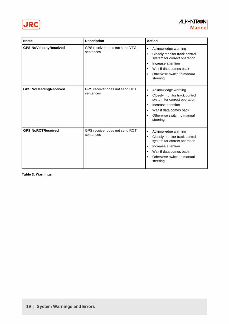
Name Description Action
GPS:NoVelocityReceived GPS receiver does not send VTGsentences
• Acknowledge warning
• Closely monitor track controlsystem for correct operation
• Increase attention
• Wait if data comes back
• Otherwise switch to manualsteering
GPS:NoHeadingReceived GPS receiver does not send HDTsentences
• Acknowledge warning
• Closely monitor track controlsystem for correct operation
• Increase attention
• Wait if data comes back
• Otherwise switch to manualsteering
GPS:NoROTReceived GPS receiver does not send ROTsentences
• Acknowledge warning
• Closely monitor track controlsystem for correct operation
• Increase attention
• Wait if data comes back
• Otherwise switch to manualsteering
Table 3: Warnings
19 | System Warnings and Errors

5 Appendix
G-005185 (3104.0724)AlphaRiverTrackPilot MFM BKWeight: 1.2 kgEnvironmental: Front IP56 /Back IP22
Figure 6: Dimensions of the AlphaRiverTrackPilot
20 | Appendix

Fron
tvie
wSi
devie
w
Botto
mvie
w
Insid
eVi
ew
1 1
2 2
3 3
4 4
5 5
6 6
AA
BB
CC
DD
Alph
aRive
rTra
ckPi
lotS
chal
tsch
rank
G-00
4528
(310
4.07
44)
0
h.ko
ppe
27-3
-201
9
-
Desig
ned
byCh
ecke
dby
Appr
oved
byDa
te
1/1
Editi
onSh
eet
Date
380
380
210
380
380
210
340
34020 20
2020
Figure 7: Dimensions of the control cabinet
21 | Appendix
All over the world,close to the customer
JRC/Alphatron Marine B.V.Schaardijk 23 (harbor 115)3063 NH RotterdamThe Netherlands
The information in this document is subject to change without notice anddoes not represent a commitment on the part of Alphatron Marine B.V.
T +31 10 453 4000 Document name : AlphaRiverTrackPilotF +31 10 453 4010 Document nr. : [email protected] Version : V1.1www.jrc.am © All rights reserved Alphatron Marine B.V.
Centers of ExcellenceHouston, Rotterdam, Singapore, Tokyo