for electron beam pulse compression-based physics
TRANSCRIPT

A Proposal to the Brookhaven Accelerator Test Facility
for
ELECTRON BEAM PULSE COMPRESSION-BASED PHYSICSAT THE BROOKHAVEN ATF
Experimenters:
Ron Agutsson, UCLA Dept. of Physics and Astronomy
Alex Murokh, UCLA Dept. of Physics and Astronomy
Claudio Pellegrini, UCLA Dept. of Physics and Astronomy
James Rosenzweig, UCLA Dept. of Physics and Astronomy, Spokesman
Aaron Tremaine, UCLA Dept. of Physics and Astronomy
Ilan Ben-Zvi, Brookhaven National Laboratory
Vitaly Yakimenko, Brookhaven National Laboratory

2
1. Electron beam pulse compression: scientific and technical interest.
This proposal seeks support for experiments to be performed using a compressed
electron beam pulse derived from a magnetic chicane-based pulse compression system
currently under construction at UCLA for the Brookhaven National Laboratory
Accelerator Test Facility (BNL ATF). This compressor will serve several experimental
purposes, both immediate and long-term. The immediate purpose, from the UCLA point-
of-view, is to install a state-of-the-art compression system, an effort funded by the Office
of Naval Research (ONR), which springs technically from earlier efforts at the UCLA
Neptune laboratory and Fermilab/DESY. Upon completion, we intend to use it to test the
as yet poorly understood physics of the compression process, such as emittance growth
due to non-inertial space-charge, and related phenomenon of coherent synchrotron
radiation generation. From both UCLA and BNL view points, then, the compressor will
allow an important test of a critical beam physics issue, the effect of these compressor-
derived effects on the gain of self-amplified spontaneous emission free-electron lasers
(SASE-FELs). This FEL work, already supported nationwide by the VISA collaboration
and at BNL/SUNY-Stonybrook by ONR, more directly addresses the issues surrounding
the generation of very short wavelength FELs such as the LCLS than previous work at
lower beam energy and current. In addition, the long-range benefit of this work is the
addition to the ATF infrastructure of a state-of-the-art bunch compression, thus allowing
an expansion of experimental possibilities at this national user facility.
From a basic beam physics viewpoint, the physical effects we propose to study as
a direct result of compressor implementation are fundamental aspects of these space-
charge dominated systems under transverse acceleration. It is necessary, in order to make
experimental progress in use of these beams, to thoroughly explore these effects, which
have little in the way of compelling measurements to allow their understanding. Of
course, the applications of these beams, specifically in the generation of coherent
radiation from high gain free-electron lasers, provides even larger motivation for the
beam physics field. For next generation SASE-FELs it will be necessary to use pulse
compressors to raise the peak electron beam current, but in the process of compression,
the quality of the electron beam’s transverse phase space may be degraded to the point

3
where there is no improvement in gain. This proposal seeks dedicated beam time at the
ATF to make experimental tests of the physical processes relevant to pulse compression,
and the concommitant transverse phase-space degrading collective effects which occur in
bend magnets. After establishment of the beam physics effects associated with the
compressor itself, we will then use the compressed beam in the VISA undulator to test
the physics of ultra-high gain FELs with such a beam as a driver. This experiment will
also be performed within the structure of the VISA collaboration. We note in this regard
that all of the listed experimenters, with the exception of R. Agutsson, are presently
members of the VISA collaboration.
2. Experimental work plan
The proposed experiment consists of the following main tasks, many of which are
already completed:
a) Simulation of ATF beam optics using TRACE-3D and PARMELA, to produce an
optimized compressor design, consistent with the constraints of the ATF beamlines.
This is complete, and discussed below.
b) Further three-dimensional coherent synchrotron radiation simulations (TREDI and
ELEGANT) to aid in understanding non-inertial space-charge effects.
c) Electromagnetic design and simulation of optimized chicane magnets (complete,
discussed below)
d) Engineering and shop design of magnets; design of vacuum vessel for chicane
transport (complete, discussed below).
e) Machining, winding, finishing testing and support of magnets (nearly complete).
f) Experimental measurement of pulse compression and coherent synchrotron radiation
at ATF.
g) Experimental measurement of emittance growth during compression at ATF.
h) Experimental measurement of ultra-high gain FEL performance with VISA.
To describe the rationale and necessary technical background behind the technical
tasks listed above, we first must review the overall motivation for the work we have

4
proposed. To this end, we note first that compression of electron beams from the
picosecond to subpicosecond regime is a subject of intense interest to the FEL and
advanced accelerator communities, as the demand for shorter pulse lengths, and high
currents, drives research forward. Methods such as velocity compression and chicane
compression have been in use for some years, but their applicability to systems in which
the beam is very bright — has high current and low emittance, are not guaranteed.
Several physics effects have been identified which may cause the degradation of beam
emittance during compression, such as non-inertial space-charge, and the related far-field
phenomenon of coherent synchrotron radiation emission. These mechanisms are very
poorly understood from the analytical and computational points-of-view, but their
understanding is critical to the success of many future FEL and linear collider projects.
Because of this, a number of laboratories, including UCLA, have begun to
experimentally investigate the processes of chicane-induced compression and emittance
growth during compression. This technique requires an rf linac-based source, such as the
UCLA Neptune photoinjector or the ATF photoinjector, with an optimally designed
chicane magnet system. In the linac, a correlated chirp in energy and time is imparted by
accelerating the bunch ahead of the rf crest. The purpose of the chicane is to remove this
correlation through the differential path lengths of the off-energy particles, thus
compressing the beam. At UCLA, the compressor has been built and implemented at the
Neptune advanced accelerator lab (see Fig. 1), and runs at 13-16 MeV. Initial
experiments on this system are presently underway, with the eventual goal of running
very low charge bunches with length shorter than 40 microns (130 fsec) for plasma
beatwave acceleration experiments. We will also be investigating the phase space-
transformation properties in general of the beam as it undergoes compression, in
particular space charge effects on the transformation. These effects include compression
degradation from longitudinal space charge, and emittance growth from both rectilinear
(velocity fields) and non-inertial (acceleration fields) transverse space charge. The non-
inertial effects are not large compared to the more well understood rectilinear effects at
16 MeV, and thus many of the most compelling questions surrounding the future use of
compressors for FELs and linear colliders cannot be answered at UCLA.

5
Figure 1. Chicane compressor magnets, along with large aperture vacuum vessel, built at
UCLA for the Neptune Laboratory
Thus we have proposed to the ONR to build a chicane compressor appropriate for
use at 70-80 MeV to be installed and used at the BNL ATF, and this proposal has been
funded for nearly a year. This higher energy system allows compression in TRACE 3D
simulations of a precompressed (using velocity compression in the gun) 150 pC beam
from 0.5 mm FWHM (1.65 psec) to 23 µm, or a factor of over twenty, which is three
times better than can be achieved at Neptune. The fact that the emittance growth in this
system is predicted by rectilinear space charge analysis allows a cleaner measurement of
the emittance growh due to coherent acceleration fields (the near field of the coherent
synchrotron radiation, CSR). For the case shown in Figure 2, the emittance growth due to
is estimated from the O’Shea-Dowell model to be between 5 and 10 mm-mrad, or an
order of magnitude better than a well-tuned ATF beam. The signal due to coherent
synchrotron radiation (synchrotron wakes) in the sub-mm regime will be large in the ATF

6
case, allowing comparison of the computational results to experiments in a way
independent of emittance measurements. This experimental arrangement is much closer
to the applications of interest, and thus is able to give more relevant information on the
phase-space density degrading properties of the compressor.
Figure 2. TRACE 3D simulation of the ATF beamline from gun exit through chicane for150 pC beam. Bunch length is given by heavy line above envelope axis, and can be seento rapidly compress inside of the chicane.
In addition to being able to make measurements on the fundamental beam physics
of compression, the ATF has two beamlines which have undulators installed on them.
This will allow the use of the highly compressed beams to drive SASE FEL experiments,
measurements which are planned by Prof. Ilan Ben-Zvi (BNL/ SUNY-Stonybrook),
under ongoing ONR support. The FEL process itself is perhaps the most sensitive
diagnostic of phase space density one can use to probe a beam — if the beam is degraded
in energy spread or emittance, it does not lase. The types of degradations one may expect
from the compression process produce highly correlated, non-thermal phase space

7
distributions. It is therefore not easy to predict analytically or computationally what the
performance of the FEL will be, and direct experiments addressing this issue become all
the more critical. This type of experiment is discussed below.
We now review the preliminary work which has gone into this project to date.
The use of the ATF beamlines, in which there is non-trivial dispersion (>80 cm) and a
tight aperture (1” beampipe), restricts the passable energy spread without clipping to
0.5% FWHM. This constraint means that the initial energy spread including chirp must
be kept small by using the shortest of beams available from the ATF. We have used the
conservative value of 1.65 psec FWHM at 150 pC to perform a design “envelope”
covering the most extreme compression cases. The TRACE3D simulations, which
include space-charge in a “water-bag” three-dimensional envelope model, have been run
using essentially the same magnetic field as the chicane magnets builts at UCLA (Figure
1) for the Neptune laboratory, B=2.1 kG.
The magnets for the ATF compressor are of course much larger in footprint than
the Neptune magnets, but are be similar, using horizontally focusing initial and final
edges of the magnet array to roughly equalize the strong vertical and horizontal focusing
of the chicane. These magnet edges are set at 20 degrees, which is the same as the
nominal bend angle. The final design of the magnets has been done with a 3D
magnetostatic code (AMPERES) simulations, an example of which is shown in Fig. 3.
This code was employed to minimize the weight of the magnets while simultaneously
insuring that the iron used does not saturate. The magnets are machined in the UCLA
shops and coated and wound in local job shops under UCLA supervision, so that quality
control is guaranteed.

8
Figure 3. Arrow plot from AMPERES simulation of ATF chicane end magnet.
A vacuum vessel for this chicane has been designed at UCLA after including
input from the demands of the beam optics, the ATF staff, and mechanical
considerations. The vessel, which has design based on the successfully deployed
Neptune chicane vacuum system, inserted into the four chicane magnets, is shown in
Figure 4.

9
Figure 4. 3D rendering of chicane magnets and vacuum vessel (viewed from below).
The magnets shown in Figs. 3 and 4 have now finished their final stages of
machining, and are being coated and wound (with air-cooled 8 gauge enamel-coated
copper wire). The magnets use a maximum excitation current of 14 A and have a
resistance of 4.25 Ohms. They will be each have separate power supplies to allow for
correct trimming of the fields. The magnets are designed with modular construction in
order to ease the installation into the ATF linac bunker, as discussed below. Installation
of the chicane and vacuum vessel into the ATF beamline is foreseen for September or
October of 2000.
The experimental plan for the time before and after installation of the chicane is
now described in more detail.
a) Simulation of beam optics. At UCLA, the first step in performing a space-charge
dominated beam dynamics simulation is to use TRACE3D, as described above. This
allows the overall envelope behavior to be deduced, as shown in Fig. 2, up to and

10
including the performance of a compressor. Figure 2 includes the effects of
acceleration and focusing in the rf linac sections of the ATF, as well as the chicane
magnets and nearby matching optics. The TRACE3D simulations form the basis of
setting up PARMELA simulations. The UCLA version of PARMELA has been
extensively modified, to include longitudinal wake-fields, and to allow better
handling of the point-to-point space-charge evaluation routine needed to model
space-charge self-consistently in an asymmetric beam. It also has much improved
phase-space diagnostics, so that the beam dynamics can be understood and optimized
straightforwardly. TRACE3D and PARMELA have been used, in cooperation with
BNL personnel running TRANSPORT, to specify the beam optics which will allow
matching of the high rms divergence (see Fig. 2) of the beam at exit of the
compressor to the rest of the ATF. The magnetic and optical characteristics of the
chicane compressor system as designed are summarized in Table 1. Only the most
extreme case of compression is quoted — other cases with larger charge and smaller
compression have also been studied. Note that in general the compression will be
significantly smaller for initially larger pulse lengths (typically accompanying larger
charges).
Beam Energy 71 MeV
Beam Charge 0.15 nC
Energy spread 0.5% FWHM
Nominal linac rf phase 17 degrees
Bend angle 20 degrees
Magnetic field 2.1 kG
Initial pulse length 0.5 mm FWHM
Final pulse length >0.023 mm FWHM
TRANSPORT R56 0.63 mm/(δp/p%)
RMS normalized emittance growth 5 – 10 mm-mrad
Table 1. Chicane optics and magnet parameters.

11
b) Further code development: Unfortunately, even our version of PARMELA cannot be
used to predict well the influence of non-inertial space-charge terms in the fields (all
of the emittance growth seen in Figure 2 is due to rectilinear, or velocity, fields). In
fact, PARMELA predicts small (~1 mm-mrad) emittance growth in that case. The
quoted emittance growths in Table 1 are larger estimates based on a semi-analytical
approximation. To improve our predictive modeling, we have begun to use two new
codes, a new three-dimensional Lienard-Wiechert code called TREDI, and
ELEGANT, a code which calculates CSR effects. TREDI has been bench-marked on
an analytical calculation of an effect of collective beam fields in bend magnets — the
diamagnetic effect of beams in undulators1— with excellent results. We have begun
to use this code on the problem at hand, the chicane, which can be seen to be merely a
version of the undulator with more dramatic bends. An initial field calculation for the
case of a chicane magnet (at 10 MeV) was also benchmarked against an analytical
model (and alternative computational model) due to R. Li2 of Jefferson Lab, as shown
in Figs. 5 and 6. From TREDI we will be able to calculate predictions for two
experimental measurements: the degree of emittance growth during compression, and
the power radiated coherently by the beam as synchrotron radiation.
Figure 5. Predicted transverse and longitudinal synchrotron “wakes” in 10 MeV bend.
(from R. Li, JLAB).
1 "Diamagnetic Fields Due to Finite Dimension Intense Beams in High-Gain Free-Electron Lasers", J.Rosenzweig and P. Musumeci Physical Review E – Rapid Communication 58, R2737 (1998).
12
-2.5
-2
-1.5
-1
-0.5
0
0.5
1
-0.005 0 0.005 0.01
F_rF_z
F (
keV
/m)
s (mm)
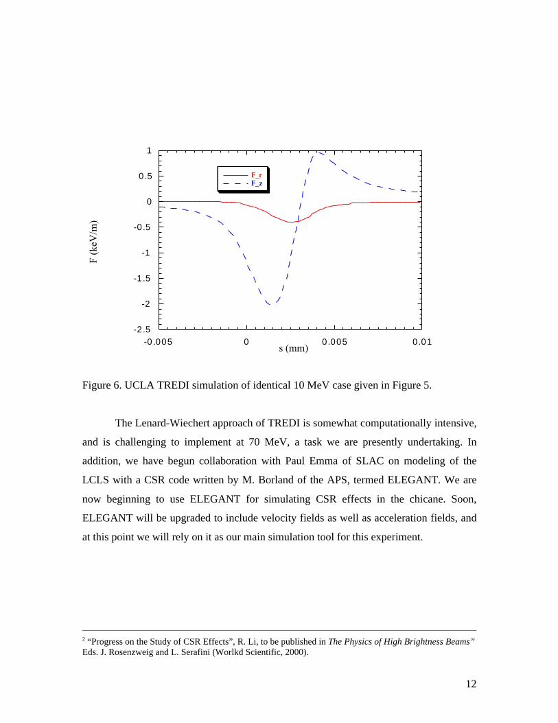
Figure 6. UCLA TREDI simulation of identical 10 MeV case given in Figure 5.
The Lenard-Wiechert approach of TREDI is somewhat computationally intensive,
and is challenging to implement at 70 MeV, a task we are presently undertaking. In
addition, we have begun collaboration with Paul Emma of SLAC on modeling of the
LCLS with a CSR code written by M. Borland of the APS, termed ELEGANT. We are
now beginning to use ELEGANT for simulating CSR effects in the chicane. Soon,
ELEGANT will be upgraded to include velocity fields as well as acceleration fields, and
at this point we will rely on it as our main simulation tool for this experiment.
2 “Progress on the Study of CSR Effects”, R. Li, to be published in The Physics of High Brightness Beams”Eds. J. Rosenzweig and L. Serafini (Worlkd Scientific, 2000).

13
c) Electromagnetic design and simulation of optimized chicane magnets: complete, see
above.
d) Engineering and shop design of magnets; design of vacuum vessel for chicane
transport: The magnets have been engineered in consultation with the UCLA shop,
which has not only produced the dipole magnets shown in Figure 1, but also a new
generation of Neptune chicane dipoles, precision quadrupoles and steering magnets
(see Figure 5) now in use at UCLA, DESY, Fermilab, and Brookhaven. We have
incorporated the vacuum vessel into the design in consultation with ATF personnel,
to insure maximum aperature (14 mm) in the narrow dimension, while obeying
constraints due to the magnetic circuit and gap, as well as mechanical deflection
under vacuum (<10 microns). Both magnets and vessel have been designed with
modular pieces for ease of assembly. The vessel has also been designed with metal
gasket knife-edge seals to allow high bake-out temperatures, and vacuum consistent
with the rest of the ATF injection line.
e) Machining, winding, finishing testing and support of magnets: The construction of
the chicane magnets, as indicated above, is nearly complete. The precision machining
of yoke and pole pieces for UCLA magnets is performed with the aid of a computer
controlled CNC cutting machine. The magnets are finished and wound at local job
shops. After construction, we will undertake a complete field mapping and saturation
test on the magnets before shipping them from UCLA to BNL in the summer of 2000.
The stands and alignment rails to be used inside of the ATF are presently under final
design, pending discussions with ATF engineers. The present status of the design is
shown in Fig. 7. Note the access port at the upper right hand corner of the vessel to
allow measurement of CSR from the exit of magnet 3 and entrance of magnet 4.

14
Ronald [email protected]
roof
floor
Vacuum access
60.9
6
30.4
8
Off-axis Paraboloid
Note: Green paths represent beam deflections at 5 deg increments
Figure 7. Side view of chicane magnets and vacuum vessel in ATF injection line bunker.
The previous development of chicane dipoles, precision quadrupoles and steering
magnets at UCLA has necessitated the building of numerous Hall probe test stands for
measuring magnetic field profiles. Numerous power supplies are available for energizing
the magnets, as is a degaussing supply for studying the elimination of remanant fields.
f) Experimental measurement of pulse compression and coherent transition radiation at
ATF: While we have developed many methods for the measurement of bunch charge,
emittance and pulse length at UCLA, it will not be necessary to bring all of these to
the ATF, as this facility has developed more energy-appropriate methods of their own
to measure these quantities. We will therefore use the ATF infrastructure for
measurements and data acquisition where possible, in determining emittance growth
as a function of charge. On the other hand, at BNL pulse length is now typically
measured using a linac phasing and momentum spectrum technique which cannot be
used with a compressor. At UCLA, however, we have developed, in collaboration
with Prof. Uwe Happek of the University of Georgia, a pulse length measurement
system based on coherent transition radiation, as shown schematically in Figure 8.

15
e-beam
collecting lens
CTR foil
45°-polarizing beam splitter
90°-polarizingbeam splitter
reflectors
Golay cell
translator
Golay cell
focusing mirror
focusing mirror
Figure 8. The UCLA coherent transition radiation-based interferometer.
This measurement system is based on collection of the coherent transition radiation
(CTR) emitted at a 45 degree foil. Half of the coherent radiation is then sent into a
reference detector, and half into a polarizing Michelson interferometer. Autocorrelations
of the CTR, and thus, because the coherent portion of the radiation intensity is
porportional to the instantaneous current, the beam profile itself is made possible in this
way. An example of the data obtained from the CTR interferometer is shown in Fig. 9.
The non-unipolar autocorrelation displayed arises by the filtering of long wavelength
radiation by the effects of diffraction in the collecting optics and the interferometer. This
problem has been taken out of the data in analysis using a time-domain fitting procedure

16
developed at UCLA3. This type of measurement is now routine at several laboratories
worldwide.
0.0
0.1
0.2
0.3
0.4
0.5
0.6
0 2 4 6 8 10 12 14Nor
mal
ized
sig
nal (
A/B
)
t (psec)Figure 9. Autocorrelation of beam-derived CTR data from Neptune photoinjector using
interferometer of Fig. 8.
We propose to bring the UCLA CTR interferometer to measure coherent synchrotron
radiation (CSR) with this device, as a way of measuring the bunch length, and completing
the experimental picture of non-inertial space-charge and related radiative effects during
the compression process. The CSR will be observed at either the off-axis port shown in
Fig. 7, or by use of a downstream mirror. The Golay cells will be easily sensitive to the
predicted CSR values, which can be two orders of magnitude larger than those observe in
CTR measurements at UCLA. The minimum resolvable bunch length of this device is
100 microns FWHM (due to the wire grid spacing in the transmission polarizers),
3 "Bunch length measurement of picosecond electron beam from a photoinjector usingcoherent transition radiation" A. Murokh, J. Rosenzweig, et al., Nuclear Instruments andMethods A 410, 549 (1998).

17
however. We thus will be able to obtain a calibrated measurement of compression to this
level, but must work harder to resolve shorter pulse lengths. We will initially use a total
power measurement at the straight-through port, which will be calibrated to the
interferometric measurement at longer wavelengths.
We also plan to develop new beam splitter techniques with Happek in order to
extend the resolution of the interferometer itself to shorter bunch lengths. This is also
important in that we need to eventually resolve the shorter wavelengths of CSR in order
to compare with theoretical model calculations. One can see that measurements of CSR
and pulse length are in fact not at all separate in this system.
g) Experimental measurement of emittance growth during compression at ATF. This
measurement will be performed using the standard quadrupole scanning system in use
at the ATF, with pulse length calibration obtained from the CSR system.
h) Experimental measurement of ultra-high gain FEL performance with VISA. The end-
game of all of these studies is to provide a high quality compressed beam to the
experimental beamlines of the ATF. The most compelling use of such beams on
presently installed experiments is undoubtedly VISA, which will benefit enormously
from the higher beam brightness the compressor should provide. This is shown in Fig.
11, which displays GENESIS (3D time-dependent FEL code) simulations of the
expected gain due to a beam compressed to a (slightly derated) 35 micron FWHM
bunch length, for 5 and 10 mm-mrad cases, respectively. The distance to saturation is
shortened from the standard VISA design of slightly below 4 m, to between 2.3 and 3
m. These gain curves display curious artifacts, however, due to slippage, which is
over 150 microns in this case, much longer than the beam. Thus direct measurement
of slippage effects is possible, e.g. the effect seen in the 10 mm-mrad case where the
beam head saturates first, and the tail last, leading to a much “softer” saturation
profile. While this experiment is obviously of high importance to the FEL
community, it is predicated on the success of the previous measurements, and on the
development of good beam transport from the compressor to the experiment in the

18
presence of a relatively large energy spread. It is thus foreseen that this phase of
experimentation will not begin in this ATF experimental cycle (before 7/2001).
Figure 11. GENESIS (3D time-dependent FEL code) simulations of the expected gain
due to a 150 pC beam compressed to a 35 micron FWHM bunch length, for 5 (solid line)
and 10 (dashed line) mm-mrad cases, respectively.
3. Estimated beam time needed for the experiment
It is presently foreseen that the compressor will be installed by the end of October 2000.
From November 2000 to the end of June 2001, we anticipate that we will need 20 ATF
shifts, or an average of 2.5 per month for compressor studies. At the end of these studies,
a coordinated proposal for further beam time will be made with the VISA collaboration.

19
4. Suggested location on the ATF experimental floor/interference with existing
equipment
The exact layout of the beamline between the end of the linac to the bend out of the
injector bunker is being coordinated at present with the ATF personnel, as it is being
upgraded in several ways, including the addition of the compressor.
5. Needs for equipment and/or manpower from the ATF
The ATF is providing engineering support, as well as collaboration of physicists, to this
project. At present we are coordinating the vacuum design, supports, and alignment
systems. We are also collaborating on optics issues related to implementation of the
compressor. The ATF is of course expected to take the lead role in directing our
installation of compressor hardware. When the experiments are running, we expect ATF
support in basic beam measurements such as the emittance and charge.
6. Ability of collaboration to carry out the experiment
Financially, this experiment is fully funded through the next 12 months by ONR. This
funding supports R. Agutsson and a portion of the PI (Rosenzweig), as well as all
hardware and travel. The other UCLA members of this collaboration are supported by the
VISA collaboration, which is funded by BES as a component of the LCLS program. The
UCLA team consists of a number of experimentalists who have developed hardware and
performed experiments in high brightness beam physics and SASE FELs in the recent
past. Two of the UCLA members of the collaboration are now stationed at BNL full time,
A. Murokh (graduate student), and A. Tremaine (post-doc, VISA experiment manager).
R. Agutsson will be also heavily involved in installation at BNL. The experiment is being
directed by the spokesman, J. Rosenzweig.