fog hornnsgl.gso.uri.edu/nhu/nhut09002.pdf · fog horn university of new hampshire undergraduate...
TRANSCRIPT
Fog Horn University of New Hampshire
Undergraduate Ocean Research Project 2008‐2009
4/26/2009
Team Members: Mathieu Feraud Dan Fournier Wyatt O'Day Marc Ouellette
Advisors: Kenneth Baldwin, Ph.D.
Alan Drake, Ph.D.

Table of contents
Sections
Acknowledgments Page 3
I. Abstract Page 4
II. Introduction Page 5
III. Background Page 6
IV. Methods Page 7
V. Discussion Page 9
a. Drivers Page 9
b. Case Design Page 9
c. Amplifier Circuit Design Page 11
d. Microcontroller Design Page 12
e. Fog Horn Testing Page 13
VI. Results Page 15
VII. Conclusion Page 19
Appendices
A. References Page 21
B. Microcontroller Code Page 22
C. Test, Measurement, and Diagnostic Equipment Page 26
D. Case Schematics Page 27
E. Amplifier Circuit Layout Page 33
F. Bill of Materials Page 35
G. Fog Signal Design Criteria Page 36
Acknowledgements This work is the result of research sponsored in part, by the National Sea Grant College Program,
NOAA, Department of Commerce, under grant #NA06OAR4170109 through the New Hampshire Sea
Grant College Program.
The fog horn design team would like to acknowledge the following persons and entities, whose
contributions and guidance made the successful completion of the project possible.
Kenneth Baldwin, Ph.D.
Alan Drake, Ph.D.
Jennifer Bedsole
Paul Goodwin
Watermark Navigation Systems, LLC
3
I. Abstract Audible warning signals are necessary for ensuring the safety of nautical vessels in inclement
weather conditions where a visible navigation beacon may become obscured. An engineering challenge
exists in designing a commercially viable fog horn which is simultaneously lightweight, low profile,
weather resistant, has low power consumption, and yet is powerful enough to produce an audible signal
over a great distance.
This design team has endeavored to design a fog horn prototype which meets or exceeds the
specifications set forth by the customer, while keeping the design flexible enough that the customer
may implement design changes in the future.
4
II. Introduction Warning signals have been used for centuries as a method for warning nautical vessels of the
presence of hazards and obstacles in open water. Such signals become necessary when visibility
conditions are such that a warning beacon cannot be seen in time for the ship to change course. Thus,
the nautical warning signal‐‐ or foghorn, as it is more commonly known‐‐ is an invaluable tool for
navigation. The prevalence of off‐shore oil platforms makes the modern foghorn especially important
to modern seafarers.
Watermark Navigation Systems, LLC is the manufacturer and distributor of a wide range of
nautical aids, including marker buoys and signal beacons. Watermark found that a common complaint
amongst their customer base was the lack of an inexpensive, lightweight, and low‐maintenance foghorn.
Seeing this opportunity to meet a market need while expanding their product base, Watermark
approached the University of New Hampshire with the proposal to sponsor an undergraduate project
team in the design of such a foghorn.
Though it is relatively simple in concept, a viable foghorn presents unique challenges to a team
of engineers. One must consider the environment in which the horn is to operate. The foghorn will
constantly be exposed to moisture and salt from seawater. It must be able to withstand wind and heavy
rains as well as a wide range of temperatures. It must be small and light enough to make transportation
out to its installation site economically viable. In contrast, it must be rugged enough to remain
unaffected by a harsh outdoor environment. Most importantly, it must produce a signal which is
audible to a vessel at distances far enough to avoid the obstacle. The production of such a powerful
audible signal carries with it its own engineering challenges in terms of the power required to produce
it.
Thus, the aim of this project team was to approach this unique and very real engineering
challenge and devise a foghorn which would meet the specified criteria and serve as the prototype for
Watermark’s own line of foghorns. The team consisted of a small, interdisciplinary group of engineers
who saw in this project the opportunity not only to innovate but to also gain the experience of having
guided an idea through the stages of design to emerge with a marketable product.
5
III. Background When Paul Goodwin of Watermark proposed the foghorn project to the University, he included
in the project description several features that he expected the final foghorn to possess. Obviously, the
design constraints mentioned earlier were mentioned. These specific design goals can be seen in
Appendix G: “Fog Signal Design Criteria”.
Principal among these constraints was the production of an audible signal of specific duration
and loud enough and to meet the Coast Guard specification. The primary criteria of this specification
are that the signal must be approximately 120 decibels at 1 meter and that it persists for 2 seconds over
a 20 second interval.
6
IV. Methods The exact approach that the design team would take to meet this benchmark was not
immediately clear. Many methods exist by which sound can be created. A historical investigation of
foghorns revealed that the earliest fog signals were bells. At the turn of the century, compressed air
horns such as diaphones were widely used. Most commercially available modern foghorns use
compression drivers or other electromagnetic loudspeakers to produce sound. Other methods also
exist, such as vibrating plates and piezoelectric speakers, which can produce audible signals.
The design team began by performing a feasibility study into each of these methods in order to
determine if some viable method of sound production existed beyond loudspeakers that could meet the
design criteria. The team examined four such approaches: a mechanical bell, a piezoelectric speaker, a
compressed air horn, and a method utilizing vibrating plates.
The mechanical bell idea was quickly discarded after the realization that the size of the bell
necessary to produce sound pressure levels exceeding 120 dB would be prohibitively large. The
mechanical apparatus necessary to strike the bell at the specified 20 second interval would necessitate
the use of a motor or other such electro-mechanical device which would decrease the maintenance
interval of the signal as well as significantly add to its weight and overall power consumption.
The piezoelectric speaker also proved to be an intractable approach. Though piezoelectric speakers are
small and consume very little power, the amount of sound pressure they are capable of producing is
likewise small. Suitable for applications such as hearing aids and earphones, where they can directly
stimulate the eardrum, the piezoelectric driver cannot come close to providing sound pressure levels
appropriate to our application.
Compressed air offered the team the first viable approach to meeting the audible signal criteria.
Many compressed air systems, such as the ones used on tractor trailers and locomotives, exist which
meet or exceed the 120 dB sound pressure level needed for the horn. A compressed air system
activated by a solenoid could be electronically controlled and would be well protected from moisture.
The major factor that diminishes the viability of the compressed air system is the necessity to include a
compressor on-site. Though a compressed air bottle would power the horn for a short time, the
frequency with which it would need to be recharged makes this approach prohibitive as technicians
would have to travel back and forth to the horn to replace these bottles. A compressor on site is the
only approach which makes any sense; however, a compressor is expensive, heavy, is susceptible to
7
moisture, consumes a great deal of power, and necessitates routine maintenance. For these numerous
reasons, the compressed air approach was deemed to lie outside of the possible design approaches for
the foghorn.
The vibrating plate approach was lastly considered. A relatively obscure technology, it utilizes
rods affixed to a series of thin plates which are made to vibrate by quick back-and-forth movements of
the rods themselves. Few vibrating plate loudspeakers exist, and the ones that do are marketed as
high-frequency loudspeakers for audiophiles. Though they consume less power and offer a frequency
response better than that of a traditional loudspeaker, the unavailability of these devices coupled with
the complexity of manufacturing one made this an approach which the team was reluctant to explore
due to the constraints of time and budget.
Thus, the design team decided that for the factors of small size and weight, coupled with
commercial availability and ease of implementation, the use of electromagnetic compression drivers
made the most sense.
8

V. Discussion After choosing the compression drivers as the method to make sound, we then began breaking
the problem of making a working fog horn prototype into approachable pieces.
a. Compression Drivers
A wide array of loudspeakers are commercially available, and thus it became necessary to
“narrow the field” for drivers which would be appropriate to the fog horn application. The first criterion
which the driver had to meet was the ability to provide at least the specified sound pressure level given
a reasonable power signal. Secondly, the driver must operate well within the region of the horn’s signal
frequency. According to the Coast Guard specification, this includes tones as low as 400 Hz and as high
as 1.2 kHz. A criterion which became apparent after attempting to order several drivers was the actual
commercial availability of the driver itself. Some drivers were discovered which could meet the
demands of our horn, but which turned out to be manufactured by a company that had gone out of
business or had ceased carrying the product.
The drivers on which the design team eventually settled were the Electro Voice® ID60DT heavy‐
duty compression drivers. These high power industrial drivers featured a ruggedized design, a sealed
wiring compartment, tropicalized metal parts for resistance to humidity, and weatherproof paint. The
ready availability and its weather‐resistant features made it ideally suited for implementation into the
horn design. The threaded 1 3/8” throat of the driver provided us with an easy way to mate the driver
to the horn channel, an engineering difficulty we were thankfully able to bypass.
b. Case Design
The design of the fog horn must meet certain criteria, the most important of which is the Coast
Guard specification for sound pressure level at one meter. This audible signal would ideally be projected
in a horizontal pattern, 360 degrees around the horn. The second criterion, for commercial purposes, is
providing a fog horn that is lightweight enough to be easily transported by helicopter or small boat out
9

to the installation site. The fog horn drivers and electronics must be protected from the elements and
the horn itself must be weatherproof and resistant to salt water.
When inspecting the structure of a Bogen nautical loudspeaker, the team noticed that the sound
traveled in three different directions before leaving the speaker. The loudspeaker itself had three
different sections, each shaping and directing the audible signal. In the first section, the sound travels
from the driver up through a tuned channel. In the second, a cap encircling the initial tube projects
sound back down and around the initial tube. The last section features another cap, which directs and
projects the sound back upward and out. This particular design offered a method by which the drivers,
or source of the sound, could be isolated from direct exposure to the environment.
In designing the actual horn, the team went through several different approaches. The initial
designs were unnecessarily complex, in that they demanded three different parts to be made in conical
shapes and were of extremely precise dimensions. In most of these suggested designs, there were only
three parts that were acoustically essential: the inner horn, the cap and the waveguide. Initially, all three
were designed in conical shape, with the wave guide at a significant angle. The wave guide was designed
as two pieces so that it could be clasped on the horn while allowing for access to the drivers. This design
required a precise fit to the inner horn‐‐ whose width varied according to height‐‐ and to the base. This
approach was abandoned in the final design, as was the cap which now rested at a perpendicular angle
to the top.
The design submitted to Watermark had only two complex parts. Due to the difficulty of
fabricating these parts, Watermark made several alterations to the design, which they felt would
simplify fabrication.
The final design is divided into five segments, each with specific acoustic and structural roles
within the fog horn.
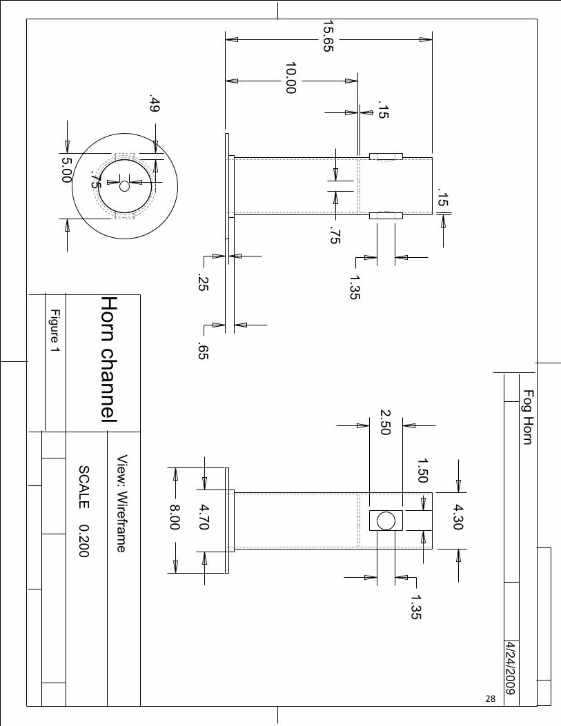
The horn channel, as shown in Appendix D figure 1, serves as the base and central column of the
horn. It supports both drivers from the threaded inserts on its sides. The threaded rod runs vertically
through its center and locks into place with bolts. The tuning plug is positioned inside the channel
between the drivers, with the top edge perpendicular to the drivers. The inner horn is threaded to the
top of the channel.
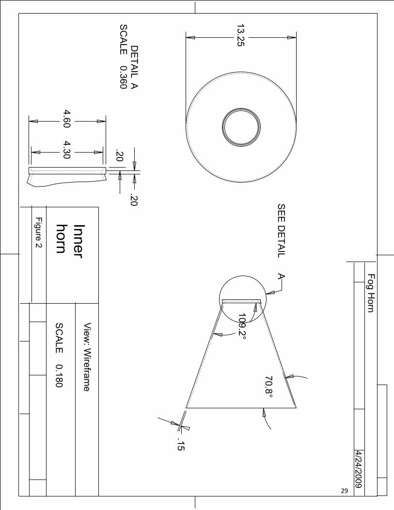
The inner horn (Appendix D figure 2), is used to direct the sound to the top of the cap and match
the acoustic impedance of the channel to the cap. In the prototype, it also supports the wave guide. It is
attached to the channel by threads at its mouth.
10
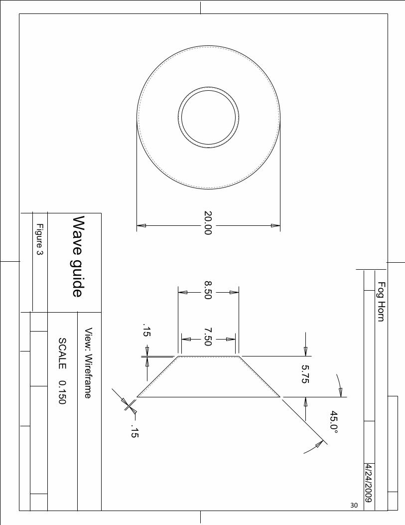
The wave guide (Appendix D figure 3), is used to further direct sound reflected from the cap. It
converts the vertical sound waves which reflect from the cap, to horizontal ones that propagate from
the horn. It is welded to the inner horn.
The cap (Appendix D figure 4) directs the sound from the inner horn to the wave guide. It is
suspended from the threaded rod by bolts. Its large top surface allows for the mounting of signal
beacons on buoys where space is limited. Its long sides further redirect sound energy, while protecting
the horn channel from encroachment of water.
The tuning plug (Appendix D figure 5) is used to redirect the sound of the two drivers up the
horn channel. Its main purpose is to avoid having the drivers directing sound only into each other. It is
placed inside the horn channel with its top edge perpendicular to the drivers. The tuning plug is made
out of PVC.
The prototype was made completely out of ¼” aluminum with the exception of the tuning plug. The
total weight of the horn is 59.2 pounds and it is 34.5” high (excess bar is 12”) and 20” wide.
c. Amplifier Circuit Design
The fog horn power amplifier circuit is a multifunctional, low power circuit used to drive the two
60‐watt compression drivers. The principal consideration in the design of the amplifier was maximum
efficiency, since the fog horn would be operated by battery. The more efficient the amplifier circuit, the
less often these batteries would need to be replaced.
An electromagnetic driver works by feeding current through it in a forward or reverse direction
to get the diaphragm to move in the corresponding direction by an amount proportional to the current
itself. The limitation our design team faced is that a single 12‐volt DC battery only produces a polarized
voltage. This led us to the idea of incorporating an integrated circuit called an H‐bridge into our circuit
design. The H‐bridge, in a basic sense, works by sensing a PWM (pulse‐width modulation) input with
multiple transistors to enable a sequence of switching to take place. The switching pattern determines
at what times the current flow is forward or reversed at the outputs of the H‐bridge. Reversing the
direction of current flow allows the amplifier to use the entire range of motion of the loudspeaker
driver, overcoming the limitation of the polarized battery. To control the circuit, our team determined
that the best method for producing the PWM control voltage was to use a microcontroller. Through the
11
utilization of the H‐bridge and microcontroller our team was able to design and fabricate a properly
functioning circuit that maximizes the overall efficiency of the foghorn.
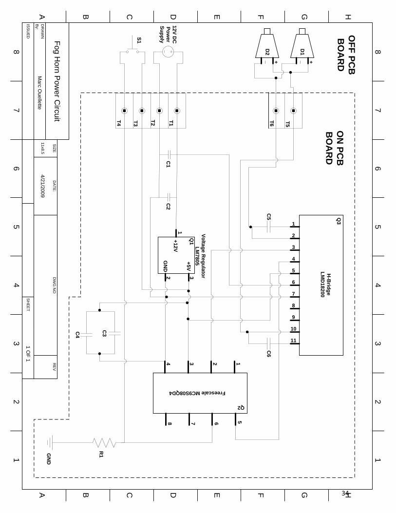
Referring to the circuit schematic, (Appendix E) the microcontroller (Q2) requires a supply
voltage of 5 volts DC. To provide this, a 5 volt voltage regulator (Q1) is used. Capacitors C1, C2, C3, and
C4 act as coupling capacitors which keep AC noise off of the DC voltages coming out of the battery and
voltage regulator. Capacitors C5 and C6 are used as part of the bootstrap circuitry of the H‐bridge. This
feature speeds up the rise and fall times of the output signal.
The microcontroller is programmed to output a TTL square wave with a 20 second period, a 10%
duty cycle, and a burst frequency of 950 Hz. Pin 6 of the microcontroller connects to switch S1 and is
held low during normal fog horn operation. Closing the switch S1 asserts this pin high and signals the
microcontroller to shut the circuit down for two hours. This feature is included for the benefit of
maintenance personnel who may be working in the vicinity of the foghorn without the benefit of
hearing protection. The microcontroller will then automatically resume normal operation after 2 hours
have elapsed.
d. Microcontroller Design
The microcontroller is the brain of the Fog Horn. It generates the 950Hz sound wave, shuts off
the H‐Bridge during idle times, and implements the kill switch.
We chose an 8‐bit microcontroller from Freescale – from the HCS08 family of microcontrollers
units (MCUs). We chose the Freescale MC9S08QD4 microcontroller for its low‐price, high availability,
and easy programmability. In particular, the MC9S08QD4 microcontroller comes with timer functionality
and keyboard interrupts that allows us to implement all of the features necessary to both satisfy the
coast guard specifications and the business requirements of Watermark Navigation Systems.
We programmed the microcontroller using the C programming language. We also made use of
the header files that reference particular memory address locations. These header files are freely
available from Freescale. See Appendix B for the full code listing.
The first feature of note is the configurable timer overflow interrupt. We configured this
overflow such that the interrupt function would execute at a rate of 950.5 Hz. Within this interrupt
function we could toggle the output from 0V to 5V on a pin of the microcontroller. This 0V to 5V toggling
12

acted as the square wave input to the H‐Bridge circuit, which converted this signal to a ‐12V to 12V
square wave.
The next problem we had to solve was the 10% duty cycle; that is, generating a tone for 2
seconds, quiet for 18 seconds. We accomplished this using the RTI (Real‐Time Interrupt) configured to
execute every 8ms. Thus, the RTI function executes 250 times for every 2 seconds. This allows us to
control both the signal generation along with counting the number of minutes that the Fog Horn should
remain dead after the kill switch has been pressed.
The kill switch functionality is implemented using the keyboard interrupt. This keyboard
interrupt function is triggered when there’s a rising edge (0 to 5V) on the input pin. Within the interrupt
function we immediately stop any currently playing sound and set a counter to resume normal
functionality after 2 hours.
The MCU we chose has over 2K of extra ROM space and nearly 2K of extra RAM memory. Plus 3
free pins are available for additional inputs and outputs. This allows for additional expansion based on
market requirements.
e. Fog Horn Testing
Upon completion of the horn itself and the installation of the signal amplifier and compression
drivers, it became necessary to perform testing on the fully realized fog horn prototype. To isolate our
testing from outside interference, and to eliminate any nuisance caused by our fog horn, testing was
performed in the UNH anechoic chamber, located behind Chase Ocean Engineering. Our tests would
consist of sound pressure level measurements at specific power levels, frequencies, and positions
relative to the horn. A detailed list of the equipment used in these tests can be found in Appendix C.
Our first goal was to adjust the position of cap section and tuning plug so as to produce the
maximum possible sound output. By adjusting the PA amplifier to mimic the output power of the signal
amplifier, the test could be performed continuously as adjustments were made to the relative length of
the horn channel – the distance between the tuning plug and cap. Similarly, we were able to vary the
frequency into the amplifier from the waveform generator. This allowed us to “zero in” on the ideal
combination of horn channel dimension and operating frequency.
The purpose of the cap/waveguide approach was to produce a consistent horizontal sound wave
360° around the fog horn. However, our testing revealed that the sound pressure level was not
consistent with position relative to the horn. This was verified by taking the sound level measurement
13

in 10° increments relative to the position of the original measurement, while maintaining a constant 1
meter distance from the horn.
14

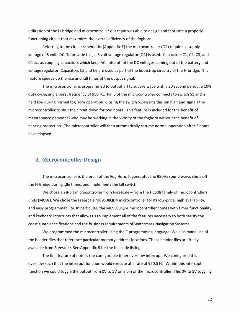
VI. Results Our testing revealed that the ideal setup for the foghorn occurred when the edge of the cap
section was approximately 9.0“above the surface of the waveguide section, and the signal tone was
tuned to 950.5 Hz. This produced a sound pressure level of 120 dB at 1 meter for an input power of
23.76 Watts during the 2 second burst of sound, and 0.13 Watts during the 18 second idle time.
Below are the measurements of the prototype fog horn measured at 1meter with a SPL Meter
with an accuracy of ±2 dB:
Table 1: Directivity test of fog horn at 1m
Degrees SPL(dB) Degrees SPL(dB) Degrees SPL(dB) Degrees SPL(dB)
0° 120 90° 120 180° 118 270° 120 10° 119 100° 117 190° 118 280° 120 20° 118 110° 118 200° 118 290° 120 30° 120 120° 119 210° 118 300° 119 40° 120 130° 117 220° 119 310° 118 50° 120 140° 117 230° 118 320° 120 60° 119 150° 120 240° 117 330° 118 70° 119 160° 117 250° 117 340° 118 80° 120 170° 119 260° 118 350° 119
15
Figure 1
50
100
150
90°
270°
180° 0°
Measured Omni-directional SPL Output of Fog horn vs. Coast Guard Specification
Degrees from Center
SPL (dB)
Coast Guard Specified SPL (119.3 dB)
Measured Foghorn SPL
16

Figure 2
Testing the output of the voltage regulator, microprocessor, and H‐bridge of our circuit revealed
that the circuit was working as designed. Referring to table 2, one can observe that our fog horn’s
quiescent power consumption is .2812 watts while the horn is not transmitting. During signaling, the
foghorn consumes of 23.76 watts for the period of 2 seconds. The total calculated power consumption
per hour is 4.29KW/h. Testing reveals that during broadcast, the amplifier draws 23.76 watts from the
supply and delivers 22.2 watts of power to the drivers. This represents an overall electrical efficiency
rating of 93.4%.
0 2 4 6 8 10 12 14 16 18 20 22 24 26 28 30 32 34 36 38 40-15
-12
-9
-6
-3
0
3
6
9
12
15
Time (S)
Am
plitu
de (
Vol
ts)
Measured Operation Cycle of Foghorn AmplifierDuration = 20s; Duty Cycle = 10%
Burst Frequency = 950 Hz
17

Table 2: Fog horn power consumption
Current (Amps) Voltage (Volts) Power Consumed (Watts)
2s Burst Period 1.98 12 23.76 18s Quiescent Period 0.027 12 0.2812 Full 20s period 1.85 12 22.2
Efficiency = 93.4%
Total Power Consumption = 4.29 kW/h
18
VII. Conclusion In this project we attempted to design, for commercial use, a viable fog warning signal. This
foghorn would be of a rugged, weatherproof design, would be light and low profile enough to permit
transportation in a helicopter or small boat, and would produce an audible signal meeting or exceeding
the standards of the US Coast Guard.
Our specific design approach attempted to produce such an audible signal in every direction
relative to the horn. We further endeavored to transmit this signal in a horizontal pattern that would
deliver the maximum amount of power to vessels traveling on the water. Furthermore, our design
attempts to protect and insulate the horn channel from the incursion of rainwater, while providing a
stable platform for signal beacons or other equipment which may need to share space on a marker
buoy.
The results of the omnidirectional testing reveals that though the horn does exceed the Coast
Guard specification in certain directions, it is not within specification for others. This shortcoming is
most likely a combination of factors involving the horn bell section. Unable to fabricate the steep taper
of the bell in ¼” aluminum, Watermark was forced to use a thinner material and beat the shape by
hand. A large weld running up the side of the bell changes the acoustic properties of the horn on that
side. Lastly, the waveguide, having been fused to the horn bell, is not perfectly centered with respect to
the horn channel. Though the precise effect of each of these factors is unknown, it can be assumed that
a molded approach to mass production of the fog horn would alleviate losses from these prototype
inconsistencies.
In terms of the horn’s resistance to weather, it was realized that particularly heavy rain driven
by strong winds could encroach into the horn channel. Though the installation of a drain plug in the
channel was discussed, it soon became apparent that even with this precaution moisture could
accumulate in the throats of the drivers. A far better approach would be to direct the driver throats
vertically down, rather than horizontally as our design has done. This would also reduce the physical
strain which the drivers place on the sides of the channel. An improved design may feature a curved
horn channel, permitting the driver to be oriented in this way.
Though the foghorn meets Coast Guard specifications, it was realized through testing that the
cap section was absorbing a great deal of sound energy before reflecting it to the waveguide. This may
have been a function of a distance between cap and waveguide which was much larger than we had
19
anticipated. The original design kept this gap very small, but at some point in the fabrication process it
became impossibility. The cap reflection approach may still be feasible, but based on testing results the
team concluded that the flat shape of the prototype’s cap and its distance from the waveguide cause
unnecessary losses to the signal strength.
One of the great successes of the project was the implementation of the amplifier circuit. With
the exception of some non-ideal “crackling” in the signal output, the tone produced by the circuit was
very clear. The microcontroller performed flawlessly. The modular and waterproof design of the circuit
allows it to be “plug-and-play” for a technician servicing the fog horn. We believe this “design with a
mind to maintenance” will be a key selling point for this fog horn when it finally goes to market.
Overall, the project was a success in that it provides a stable and easily modified framework for
the design of a commercial fog horn. Subsequent ideas and features which Watermark wishes to
implement into their product can be quickly and easily realized by using the prototype as a standard or
platform for their implementation.
20
Appendix A: References Baldwin, Kenneth C.; Ph.D. Personal interview. 27 November 2008.
Drake, Allen; Ph.D. Personal interview. 9 April 2009.
Goodwin, Paul W. Personal interviews. November 2008 – April 2009.
Kolbrek, Bjørn. "Horn Theory: An Introduction, Part 1" audioXpress 2008. 14 November 2008 <http://www.audioxpress.com/magsdirx/ax/addenda/media/kolbrek2884.pdf>.
United States. Coast Guard. Department of Homeland Security. Title 33‐‐Navigation and
Navigable Waters § 67.10‐10: Operating Requirements. Washington: Coast Guard, 2008.
United States. Coast Guard. Department of Homeland Security. Title 33‐‐Navigation and
Navigable Waters § 67.10‐20: Sound Signal Tests. Washington: Coast Guard, 2008.
21

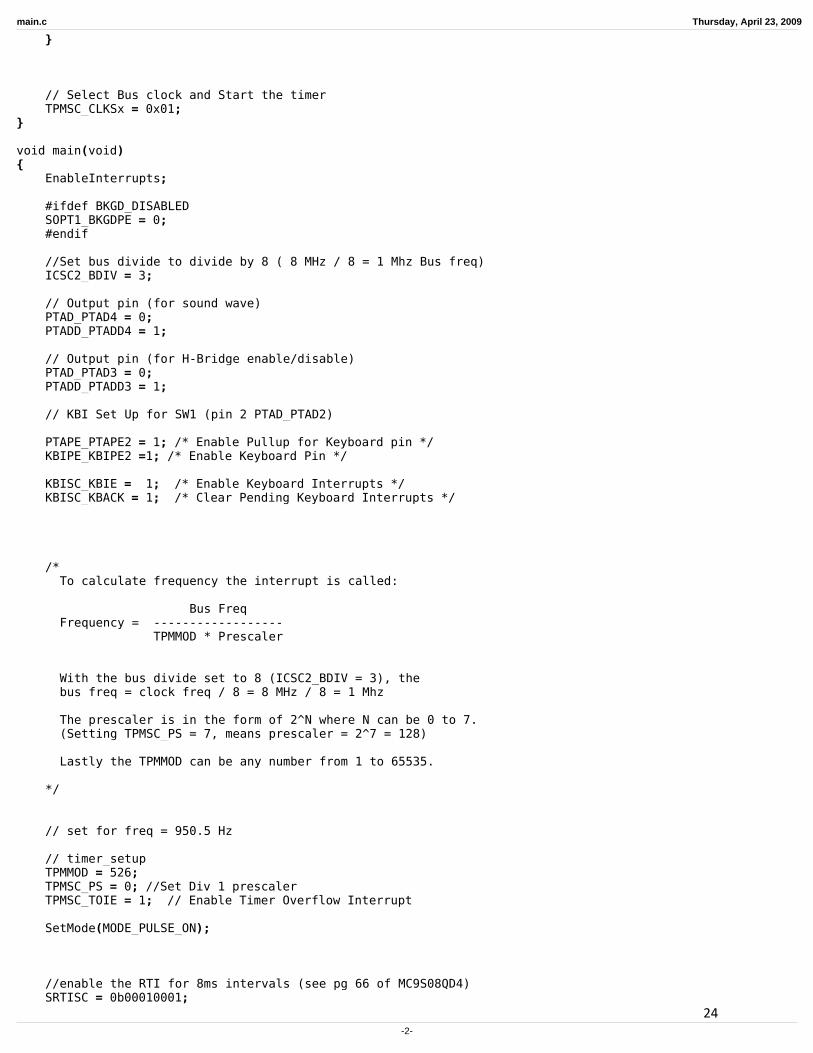
Appendix B: Microcontroller Code As discussed in section V-d (Microcontroller Design), the code is in the C programming language
and uses standard headers provided free of charge from Freescale.
22

main.c Thursday, April 23, 2009
/********************************************************************* FogHornOS*** Filename: main.c* Author: Wyatt O'Day* Contact: [email protected]* Revision: 1.4*** Last Modified: April 22, 2009** Description: Generates a 950.5 Hz square wave, 10% duty cycle * (on 2 secs off 18 secs) and has a kill switch.** Also, to reduce power consumption, the H-Bridge* will be switched off when the sound wave isn't* being generated.*********************************************************************/
#include <hidef.h> /* for EnableInterrupts macro */#include "derivative.h" /* include peripheral declarations */
#define BKGD_DISABLED
#define MODE_PULSE_ON 0#define MODE_PULSE_OFF 1#define MODE_DEAD 2
volatile byte CurrentMode;
// the amount of time the fog horn remains // dead after the kill switch has been hit#define MAX_DEAD_MINUTES 120
#define CHUNKS_IN_2SEC 250
volatile byte Minutes, PulseSeconds, PulseChunks;
void SetMode(byte mode){
//Stop and reset the timerTPMSC_CLKSx = 0x00;TPMSC_TOF = 0;
CurrentMode = mode;
Minutes = 0;PulseChunks = 0;PulseSeconds = 0;
if(mode != MODE_PULSE_ON){
// switch pin to lowPTAD_PTAD4 = 0;
// turn off the H-Bridge (5 V)PTAD_PTAD3 = 1;
return;}else{
// turn on the H-Bridge (0V)PTAD_PTAD3 = 0;
-1-
23
main.c Thursday, April 23, 2009
}
// Select Bus clock and Start the timerTPMSC_CLKSx = 0x01;
}
void main(void){
EnableInterrupts;
#ifdef BKGD_DISABLEDSOPT1_BKGDPE = 0;#endif
//Set bus divide to divide by 8 ( 8 MHz / 8 = 1 Mhz Bus freq)ICSC2_BDIV = 3;
// Output pin (for sound wave)PTAD_PTAD4 = 0;PTADD_PTADD4 = 1;
// Output pin (for H-Bridge enable/disable)PTAD_PTAD3 = 0;PTADD_PTADD3 = 1;
// KBI Set Up for SW1 (pin 2 PTAD_PTAD2)
PTAPE_PTAPE2 = 1; /* Enable Pullup for Keyboard pin */KBIPE_KBIPE2 =1; /* Enable Keyboard Pin */
KBISC_KBIE = 1; /* Enable Keyboard Interrupts */KBISC_KBACK = 1; /* Clear Pending Keyboard Interrupts */
/* To calculate frequency the interrupt is called:
Bus Freq Frequency = ------------------ TPMMOD * Prescaler
With the bus divide set to 8 (ICSC2_BDIV = 3), the bus freq = clock freq / 8 = 8 MHz / 8 = 1 Mhz
The prescaler is in the form of 2^N where N can be 0 to 7. (Setting TPMSC_PS = 7, means prescaler = 2^7 = 128)
Lastly the TPMMOD can be any number from 1 to 65535.
*/
// set for freq = 950.5 Hz
// timer_setupTPMMOD = 526;TPMSC_PS = 0; //Set Div 1 prescaler TPMSC_TOIE = 1; // Enable Timer Overflow Interrupt
SetMode(MODE_PULSE_ON);
//enable the RTI for 8ms intervals (see pg 66 of MC9S08QD4)SRTISC = 0b00010001;
-2-
24

main.c Thursday, April 23, 2009
// please make sure that you never leave this functionfor(;;) { __RESET_WATCHDOG(); }
}
// Keyboard interrupt subroutineinterrupt VectorNumber_Vkeyboard1 void KBI_ISR(void){
// kill switch was pressedSetMode(MODE_DEAD);
// Clear Pending Keyboard InterruptsKBISC_KBACK = 1;
}
// TIM1OVFL_ISR - ISR that provides the timebase.interrupt VectorNumber_Vtpm1ovf void TIM1OVFL_ISR(void){
// toggle PortPTAD_PTAD4 = ~PTAD_PTAD4;
// clear TOFTPMSC_TOF = 0;
}
// Real time interrupt - executed every 8msvoid interrupt VectorNumber_Vrti RTI_ISR(void){
// clear RTIFSRTISC_RTIACK = 1;
if(++PulseChunks == CHUNKS_IN_2SEC){
PulseChunks = 0;PulseSeconds += 2;
if(CurrentMode == MODE_PULSE_ON)SetMode(MODE_PULSE_OFF);
else if(CurrentMode == MODE_DEAD){
if(PulseSeconds == 60){
PulseSeconds = 0;
if(++Minutes == MAX_DEAD_MINUTES){
// switch back to the live modeSetMode(MODE_PULSE_ON);
}}
}else if (PulseSeconds == 18) // currently in MODE_PULSE_OFF
SetMode(MODE_PULSE_ON);}
}
-3-
25
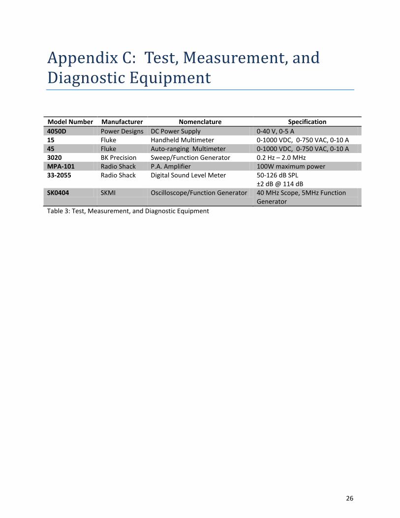
Appendix C: Test, Measurement, and Diagnostic Equipment
Model Number Manufacturer Nomenclature Specification 4050D Power Designs DC Power Supply 0-40 V, 0-5 A 15 Fluke Handheld Multimeter 0-1000 VDC, 0-750 VAC, 0-10 A 45 Fluke Auto-ranging Multimeter 0-1000 VDC, 0-750 VAC, 0-10 A 3020 BK Precision Sweep/Function Generator 0.2 Hz – 2.0 MHz MPA-101 Radio Shack P.A. Amplifier 100W maximum power 33-2055 Radio Shack Digital Sound Level Meter 50-126 dB SPL
±2 dB @ 114 dB SK0404 SKMI Oscilloscope/Function Generator 40 MHz Scope, 5MHz Function
Generator Table 3: Test, Measurement, and Diagnostic Equipment
26
Appendix D: Case Schematics
27
4.30
4.70
8.00
.15
15.65
1.35
.25.65
.75
1.50
2.50
1.35
10.00
.15
.75
.49
5.00
Horn channel
Fog H
orn4/24/2009
Figure 1
View
: Wirefram
e
0.200S
CA
LE
28
4.304.60
.20
.20
.15
13.25
70.8°
109.2°
Inner horn
Fog H
orn4/24/2009
Figure 2
View
: Wirefram
e
0.180S
CA
LE
SE
E D
ET
AIL
A
0.360S
CA
LE
AD
ET
AIL
29
5.75
.15
20.007.50
8.50
.15
45.0°
Wave guide
Fog H
orn4/24/2009
Figure 3
View
: Wirefram
e
0.150S
CA
LE
30

18.38
.25
7.50
.75
Cap
Fog H
orn4/24/2009
Figure 4
View
: Wirefram
e
0.150S
CA
LE
31

1.001.39
4.00
56.3°
.25
3.25
.70
Tuning
plug
Fog H
orn4/24/2009
Figure 5
View
: Wirefram
e
0.500S
CA
LE
32
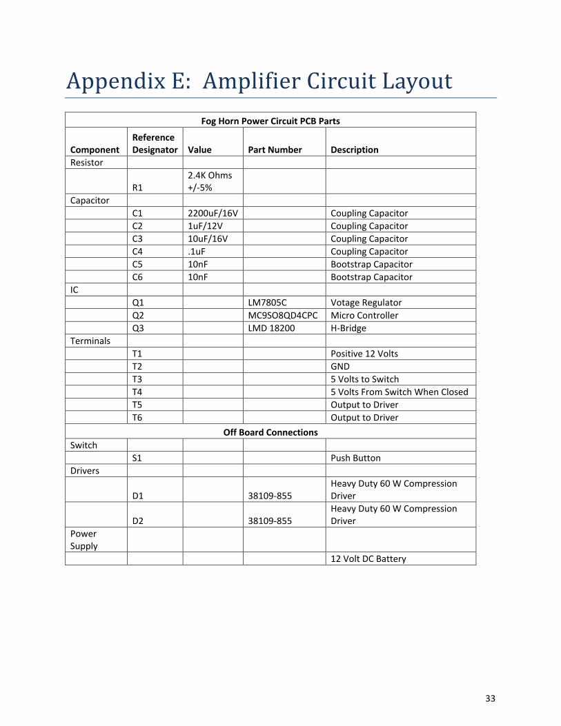
Appendix E: Amplifier Circuit Layout Fog Horn Power Circuit PCB Parts
Component Reference Designator Value Part Number Description
Resistor
R1 2.4K Ohms +/-5%
Capacitor C1 2200uF/16V Coupling Capacitor C2 1uF/12V Coupling Capacitor C3 10uF/16V Coupling Capacitor C4 .1uF Coupling Capacitor C5 10nF Bootstrap Capacitor C6 10nF Bootstrap Capacitor IC Q1 LM7805C Votage Regulator Q2 MC9SO8QD4CPC Micro Controller Q3 LMD 18200 H-Bridge Terminals T1 Positive 12 Volts T2 GND T3 5 Volts to Switch T4 5 Volts From Switch When Closed T5 Output to Driver T6 Output to Driver
Off Board Connections Switch S1 Push Button Drivers
D1 38109-855 Heavy Duty 60 W Compression Driver
D2 38109-855 Heavy Duty 60 W Compression Driver
Power Supply 12 Volt DC Battery
33
T1
T2T3
T4
HGFEDCBA
87
65
43
21
HGFEDCBA
87
65
43
21
Fog H
orn P
ow
er Circuit
DR
AW
N
By:
Marc O
uellette
ISS
UE
D
SIZ
ED
AT
E:
DW
G N
OR
EV
11x8
.54
/21/2009
SH
EE
T1
OF
1
T5
T6
C1
C2
1
2 3
Vo
ltag
e Re
gu
lator
LM
7805Q
1+
5V
+12V
GN
D
12V D
CP
ow
erS
up
ply
S1
+__ +
D1
D2
Freescale MC9S08QD4
Q2
1234
56781
2
3
4
5
6
7
8
9
10
11
H-B
ridg
eL
MD
18200
Q3
C5
C6
C3C4
R1GN
D
ON
PC
BB
OA
RD
OF
F P
CB
BO
AR
D
34
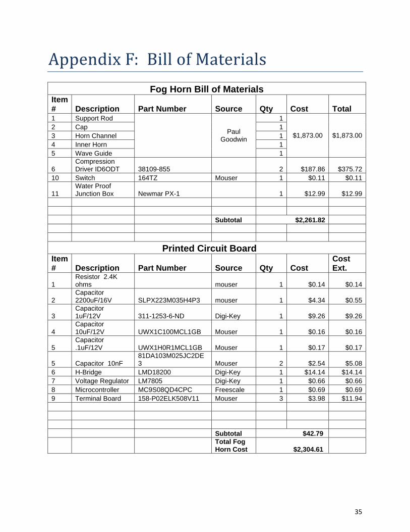
Appendix F: Bill of Materials
Fog Horn Bill of Materials Item # Description Part Number Source Qty Cost Total 1 Support Rod
Paul Goodwin
1
$1,873.00 $1,873.002 Cap 13 Horn Channel 14 Inner Horn 15 Wave Guide 1
6 Compression Driver ID6ODT 38109-855 2 $187.86 $375.72
10 Switch 164TZ Mouser 1 $0.11 $0.11
11 Water Proof Junction Box Newmar PX-1 1 $12.99 $12.99
Subtotal $2,261.82
Printed Circuit Board Item # Description Part Number Source Qty Cost
Cost Ext.
1 Resistor 2.4K ohms mouser 1 $0.14 $0.14
2 Capacitor 2200uF/16V SLPX223M035H4P3 mouser 1 $4.34 $0.55
3 Capacitor 1uF/12V 311-1253-6-ND Digi-Key 1 $9.26 $9.26
4 Capacitor 10uF/12V UWX1C100MCL1GB Mouser 1 $0.16 $0.16
5 Capacitor .1uF/12V UWX1H0R1MCL1GB Mouser 1 $0.17 $0.17
5 Capacitor 10nF 81DA103M025JC2DE3 Mouser 2 $2.54 $5.08
6 H-Bridge LMD18200 Digi-Key 1 $14.14 $14.147 Voltage Regulator LM7805 Digi-Key 1 $0.66 $0.668 Microcontroller MC9S08QD4CPC Freescale 1 $0.69 $0.699 Terminal Board 158-P02ELK508V11 Mouser 3 $3.98 $11.94 Subtotal $42.79
Total Fog Horn Cost $2,304.61
35

Appendix G: Fog Signal Design Criteria
1. USCG approval – 33 CFR 67.10 (1/2 mile and 2 mile output), for 2 second ON and 18 second OFF (see CFR sound chart for frequencies and pressure),
2. Permanent label stating; date of USCG approval, manufacturer, model name, approved range,
power input to the emitter required to meet approved output, and the power input to the entire unit required to meet approved output,
3. Solar power supply ‐ relatively low power consumption operating at 12 volts DC as unit will
include solar panels and 12V battery bank (sized based on power input requirements – TBD), less power used the better,
4. Relatively light‐weight and sized to fit into a helicopter for offshore service. Many units are
offshore and accessed only via helicopter such that size and weight will be a selling factor over units which require a workboat or supply vessel (actual design weight, etc. TBD), lighter/smaller the better,
5. Waterproof or permanently sealed electronics for long‐life in a saltwater environment. Many of
the competitors units, once opened, seem to suffer from corrosion issues after initial service. Perhaps a “module” design whereby no work would occur in‐the‐field, but components could be swapped out and serviced on‐shore or at the factory, tougher the better,
6. Temporary shut‐down circuit with waterproof switch to allow technicians the ability to
temporarily disable the signal to perform work on the structure, however, the fog signal will automatically default to ON status after a period of XX minutes OFF (TBD), perhaps including a less powerful signal to provide notice the horn will commence normal operation in 5 minutes,
7. Field testable to certify power inputs and output such that a Navaid Technician can check the
unit, in place, and verify operation to approved standards and complete MMS/USCG 90 day reporting requirements,
8. Simple operation and connectivity to existing power supply/solar installations. If an end user
already has batteries and solar panels available, our solution should simply replace the ageing or inoperative Fog Signal,
OTHER CONSIDERATIONS: 1. Possible GSM Cell Phone/Satellite connectivity for reporting capability, 2. Possible user‐programmable for various sound patterns, 3. Possible GPS synch. timing circuit to synchronize with other fog signals,
36