flying head 880 magnetic drum subsystem - … 490 real-time system flying head 880 magnetic drum...
TRANSCRIPT
UNIVAC 490 REAL-TIME SYSTEM
FLYING HEAD 880 MAGNETIC DRUM SUBSYSTEM
INTRODUCTION This bulletin describes the Flying Head-880 (FH-880) Magnetic Drum Subsystem when used as integral part of the UNlV AC® 490 Real-Time System. The subsystem provides an efficient yet inexpensive means of mass storage. Contained herein is an introduction to the flying head principle and some of the advantages the FH-880 subsystem has over other data storage devices. Included in the bulletin are system applications, physical and functional characteristics, programming information and logic flow descriptions. The extensive repertoire of instructions and basic programming examples are also included to fully acquaint you with the capabilities of the FH-880 Magnetic Drum Subsystem.
1
2
FEATURES The FH-880 Magnetic Drum Subsystem is a high-speed, large-capacity, random-access memory device. As many as eight FH-880 Magnetic Drum Units can be connected to each available input/output channel on a UNIVAC 490 Computer. Each subsystem utilizes a Channel Synchronizer and a Control Unit to control its FH-880 Drum Units.
Large Storage Capacity The subsystem's ability to record data at a high density on the FH-880 Drum allows an exceptionally large storage capacity. Each drum is capable of storing 786,432 computer words of 30 bits each.
High-Speed Random Access The subsystem is capable of addressing any drum location and provides access to the specific data in an average of 17 milliseconds with optional transfer times of 16.5, 33, 66, 132, and 264.5 microseconds-per-word. This means a possible transfer rate of more than 300,000 alpha-numeric characters per second.
Flying Head In addition to the large storage capacity and high-speed random access, the subsystem utilizes the flying head principle. This allows the read/write heads to "float" on a layer of air generated by the rotation of the drum. The FH-880 flying head technique permits a smaller head-to-drum gap which results in the higher recording density and greater read/write accuracy.
APPLICATIONS The FH-880 Magnetic Drum Subsystem operates within the UNIVAC 490 Real-Time System as a working storage for tables, file records, programs, or any large file of data which must be frequently or rapidly referenced during the running of a particular program. Some of the useful applications of the FH-880 subsystem are: Assembly and Compiling - In assembly and compiler systems a number of tables are formed and continually referenced. In some computer systems these tables are placed on tape, requiring a great deal of tape movement in searching for proper table entries. The easy accessibility and the high speed of the FH-880 subsystem reduce search and transfer time. Computer Programs - Entire programs or program segments can be stored in the FH-880 subsystem, providing the Computer with a useful extension of core memory. The immense storage capacity and speed make program storage highly practical. Mass Storage - Where large tables are required or the number of parameters for a scientific problem is large, the speed of transfer and complete address ability of the FH-880 subsystem considerably reduce running time. Sorting and Merging - The FH-880 subsystem can best be utilized by the Sort/Merge program when used as intermediate storage. All the information on a drum is merged at one time, saving many tape passes. These tape passes are the most time consuming portion of the sort and their reduction or elimination greatly reduces total time. If the drum is used, fewer tape units need be assigned to complete a given sort in a given time period.
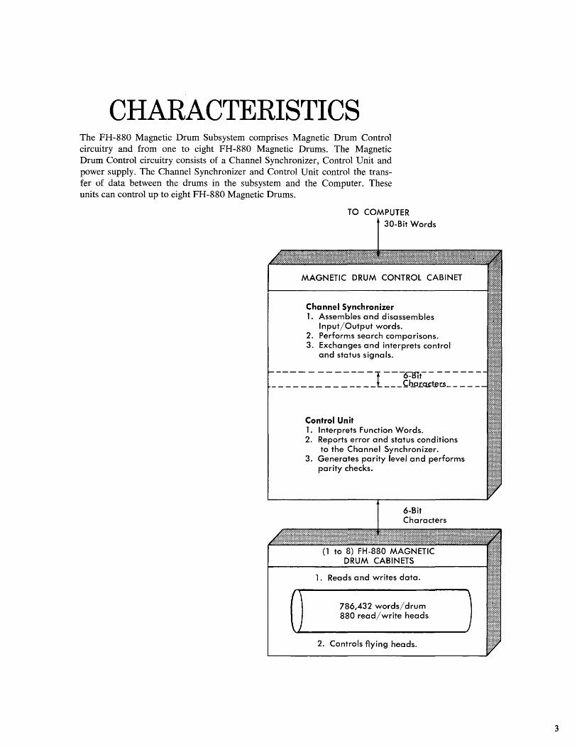
CHARACTERISTICS The FH-88G Magnetic Drum Subsystem comprises Magnetic Drum Control circuitry and from one to eight FH-88G Magnetic Drums. The Magnetic Drum Control circuitry consists of a Channel Synchronizer, Control Unit and power supply. The Channel Synchronizer and Control Unit control the transfer of data between the drums in the subsystem and the Computer. These units can control up to eight FH-88G Magnetic Drums.
TO COMPUTER 30-Bit Words
MAGNETIC DRUM CONTROL CABINET
Channel Synchronizer 1. Assembles and disassembles
Input/Output words. 2. Performs search comparisons. 3. Exchanges and interprets control
and status signals.
---- - -- ---- -l---O-mt-- ------_ _ _ _ _ _ _ _ _ _ _ _ _ _ _ __ ~b.PLQ.t~t:S ____ _
I'
\)
Control Unit 1. Interprets Function Words. 2. Reports error and status conditions
to the Channel Synchronizer. 3. Generates parity level and performs
parity checks.
6-Bit Characters
(1 to 8) FH-880 MAGNETIC DRUM CABINETS
1. Reads and writes data.
786,432 words/drum 880 read/write heads
2. Controls flying heads.
)
3
4
A drum is the medium upon which data is stored and from which the data is retrieved. The illustration shows the logical arrangement of the units and their functions within the subsystem. Drum characteristics are listed in Appendix A.
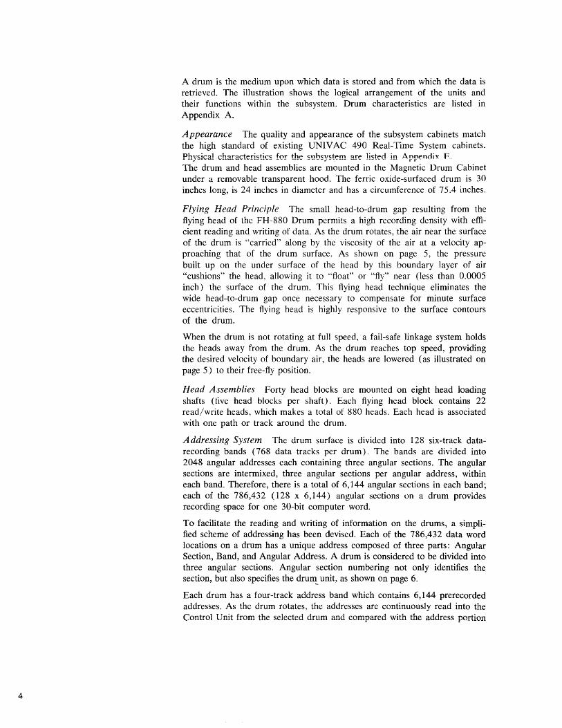
Appearance The quality and appearance of the subsystem cabinets match the high standard of existing UNIVAC 490 Real-Time System cabinets. Physical characteristics for the subsystem are listed in Arr~ndix F The drum and head assemblies are mounted in the Magnetic Drum Cabinet under a removable transparent hood. The ferric oxide-surfaced drum is 30 inches long, is 24 inches in diameter and has a circumference of 75.4 inches.
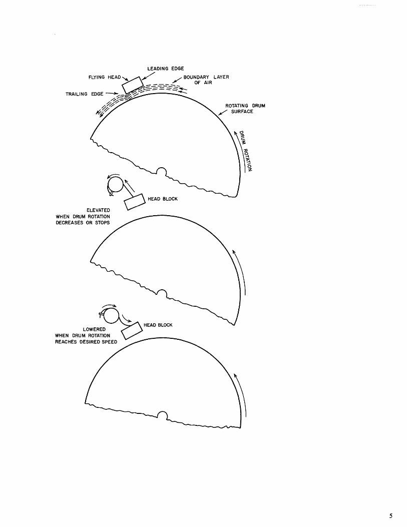
Flying Head Principle The small head-to-drum gap resulting from the flying head of the FH-880 Drum permits a high recording density with efficient reading and writing of data. As the drum rotates, the air near the surface of the drum is "carried" along by the viscosity of the air at a velocity approaching that of the drum surface. As shown on page 5, the pressure built up on the under surface of the head by this boundary layer of air "cushions" the head, allowing it to "float" or "fly" near (less than 0.0005 inch) the surface of the drum. This flying head technique eliminates the wide head-to-drum gap once necessary to compensate for minute surface eccentricities. The flying head is highly responsive to the surface contours of the drum.
When the drum is not rotating at full speed, a fail-safe linkage system holds the heads away from the drum. As the drum reaches top speed, providing the desired velocity of boundary air, the heads are lowered (as illustrated on page 5) to their free-fly position.
Head Assemblies Forty head blocks are mounted on eight head loading shafts (five head blocks per shaft). Each flying head block contains 22 read/write heads, which makes a total of 880 heads. Each head is associated with one path or track around the drum.
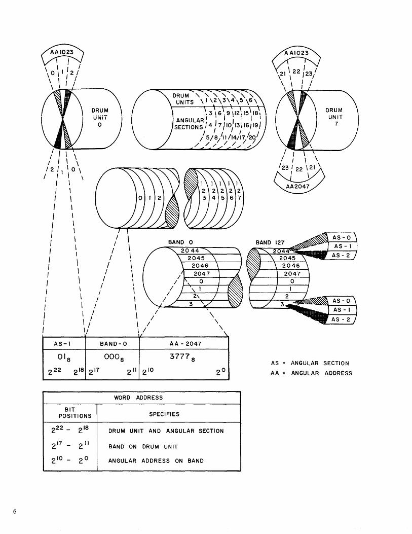
Addressing System The drum surface is divided into 128 six-track datarecording bands (768 data tracks per drum). The bands are divided into 2048 angular addresses each containing three angular sections. The angular sections are intermixed, three angular sections per angular address, within each band. Therefore, there is a total of 6,144 angular sections in each band; each of the 786,432 (128 x 6,144) angular sections on a drum provides recording space for one 30-bit computer word.
To facilitate the reading and writing of information on the drums, a simplified scheme of addressing has been devised. Each of the 786,432 data word locations on a drum has a unique address composed of three parts: Angular Section, Band, and Angular Address. A drum is considered to be divided into three angular sections. Angular section numbering not only identifies the section, but also specifies the druIl!. unit, as shown on page 6.
Each drum has a four-track address band which contains 6,144 prerecorded addresses. As the drum rotates, the addresses are continuously read into the Control Unit from the selected drum and compared with the address portion
TRAILING
~ . HEAD BLOCK
ELEVATED"" 0 WHEN DRUM ROTATION DECREASES OR STOPS
ROTATING DRUM /" SURFACE
5
6
~ ~ , I /
\ 0 \ 1 2 I \ , I I
\ , ' I
/ , \ \ I I \ \ /2 'I ' 0 \
/ I \ \ , \ I \ I \ I \ I , I \ I \ / I \ / , \ / I \ / I \ / : \ /
I \ / , \ / \ /
f \ / , \ I
I '/ AS-l BAND-O
01 8 000 8
222 2 18 217
\ \ \ \ \ \ \ \ \ \ \ / , / i
2" 2 10
AA-2047
3777 8
WORD ADDRESS
BIT. POSITIONS SPECIFIES
\.
2 0
222 - 2 18 DRUM UNIT AND ANGULAR SECTION
217 - 211 BAND ON DRUM UNIT
2 10 - 20 ANGULAR ADDRESS ON BAND
/ I / I \ \
~/23/22\21\
I \
AA2047
AS = ANGULAR SECTION
AA = ANGULAR ADDRESS
of the Function Word. When the address on the drum specified by the Function \Vord passes the address track heads, identical comparison is achieved. Reading or writing then starts in the band associated with the specified address.
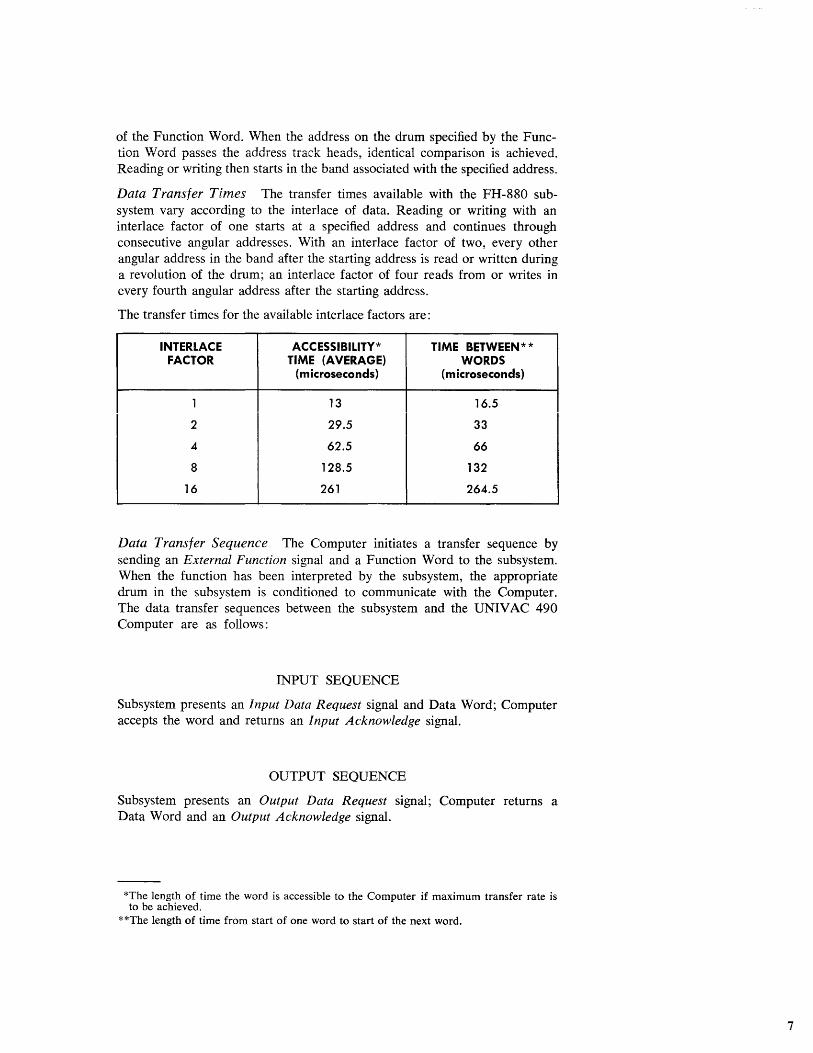
Data Transfer Times The transfer times available with the FH-880 subsystem vary according to the interlace of data. Reading or writing with an interlace factor of one starts at a specified address and continues through consecutive angular addresses. With an interlace factor of two, every other angular address in the band after the starting address is read or written during a revolution of the drum; an interlace factor of four reads from or writes in every fourth angular address after the starting address.
The transfer times for the available interlace factors are:
INTERLACE ACCESSIBILlTY* TIME BETWEEN * * FACTOR TIME (AVERAGE) WORDS
(microseconds) (microseconds)
1 13 16.5
2 29.5 33
4 62.5 66
8 128.5 132
16 261 264.5
Data Transfer Sequence The Computer initiates a transfer sequence by sending an External Function signal and a Function Word to the subsystem. When the function has been interpreted by the subsystem, the appropriate drum in the subsystem is conditioned to communicate with the Computer. The data transfer sequences between the subsystem and the UNIVAC 490 Computer are as follows:
INPUT SEQUENCE
Subsystem presents an Input Data Request signal and Data Word; Computer accepts the word and returns an Input Acknowledge signal.
OUTPUT SEQUENCE
Subsystem presents an Output Data Request signal; Computer returns a Data Word and an Output Acknowledge signal.
*The length of time the word is accessible to the Computer if maximum transfer rate is to be achieved.
* *The length of time from start of one word to start of the next word.
7
8
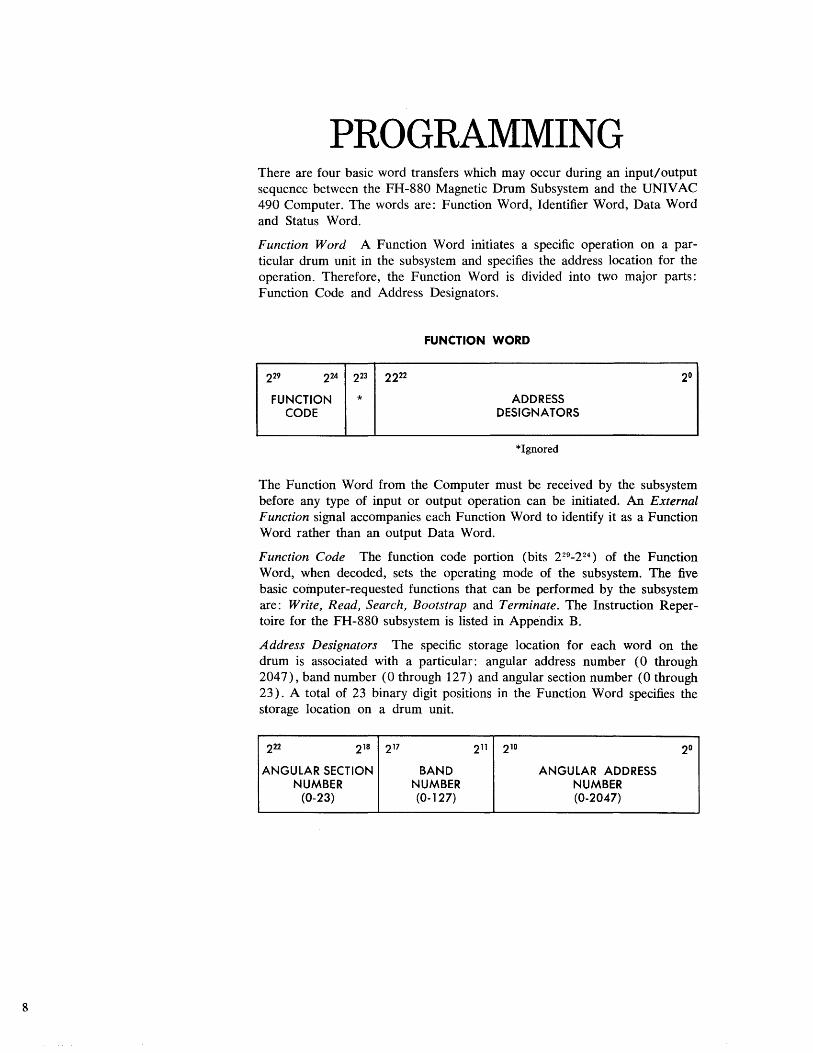
PROGRAMMING There are four basic word transfers which may occur during an input! output sequence between the FH-880 Magnetic Drum Subsystem and the UNIVAC 490 Computer. The words are: Function Word, Identifier Word, Data Word and Status Word.
Function Word A Function Word initiates a specific operation on a particular drum unit in the subsystem and specifies the address location for the operation. Therefore, the Function Word is divided into two major parts: Function Code and Address Designators.
FUNCTION WORD
229 224 223 2222 2°
FUNCTION * ADDRESS CODE DESIGNATORS
*Ignored
The Function Word from the Computer must be received by the subsystem before any type of input or output operation can be initiated. An External Function signal accompanies each Function Word to identify it as a Function Word rather than an output Data Word.
Function Code The function code portion (bits 229_2 24 ) of the Function Word, when decoded, sets the operating mode of the subsystem. The five basic computer-requested functions that can be performed by the subsystem are: Write, Read, Search, Bootstrap and Terminate. The Instruction Repertoire for the FH-880 subsystem is listed in Appendix B.
Address Designators The specific storage location for each word on the drum is associated with a particular: angular address number (0 through 2047), band number (0 through 127) and angular section number (0 through 23). A total of 23 binary digit positions in the Function Word specifies the storage location on a drum unit.
222 218 217 211 210 2°
ANGULAR SECTION BAND ANGULAR ADDRESS NUMBER NUMBER NUMBER
(0-23) (0-127) (0-2047)
Bit positions 0 through 10 designate the angular address; bit positions 11 through 17 designate the band; and the remaining five bits, 18 through 22, designate the angular section (which, in effect, also specifies a particular drum unit in the subsystem).
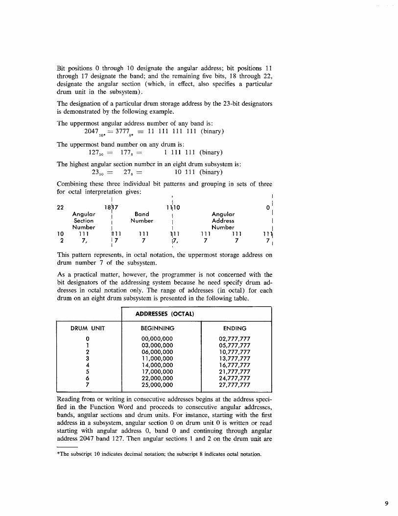
The designation of a particular drum storage address by the 23-bit designators is demonstrated by the following example.
The uppermost angular address number of any band is: 2047 == 3777 == 11 111 111 111 (binary)
10* 8*
The uppermost band number on any drum is: 12710 == 1778 == 1111 111 (binary)
The highest angular section number in an eight drum subsystem is: 23 10 == 278 == 10 111 (binary)
Combining these three individual bit patterns and grouping in sets of three for octal interpretation gives:
1 I I
18~ 7 J
01
22 11,10 Angular 1 Band 1 Angular I Section I Number 1 Address 1 Number I I Number 1
10 111 n11 111 17
1111 111 111 1111 2 7, 7 17, 7 7 71
I
This pattern represents, in octal notation, the uppermost storage address on drum number 7 of the subsystem.
As a practical matter, however, the programmer is not concerned with the bit designators of the addressing system because he need specify drum addresses in octal notation only. The range of addresses (in octal) for each drum on an eight drum subsystem is presented in the following table.
ADDRESSES (OCTAL)
DRUM UNIT BEGINNING ENDING
0 00,000,000 02,777,777 1 03,000,000 05,777,777 2 06,000,000 10,777,777 3 11,000,000 13,777,777 4 14,000,000 16,777,777 5 17,000,000 21,777,777 6 22,000,000 24,777,777 7 25,000,000 27,777,777
Reading from or writing in consecutive addresses begins at the address specified in the Function Word and proceeds to consecutive angular addresses, bands, angular sections and drum units. For instance, starting with the first address in a subsystem, angular section 0 on drum unit 0 is written or read starting with angular address 0, band 0 and continuing through angular address 2047 band 127. Then angular sections 1 and 2 on the drum unit are
*The subscript 10 indicates decimal notation; the subscript 8 indicates octal notation.
9
10
written or read in the same sequence. When angular section 2, angular address 2047, band 127 has been read, the same procedure is repeated for angular sections 3, 4 and 5 on drum unit 1, etc.
I dentifier Word The Identifier Word is a 30-bit computer word in any bit configuration. This word should follow a Function Word specifying a search instruction; like the Function \Vord, it is accompanied by an External Funcfirm ~lgn~l
The Identifier Word is used to locate specific data stored in the subsystem. When received, the Identifier Word is stored in the Channel Synchronizer, and compared character-by-character with words read from consecutive drum addresses starting at the address specified by the Function Word. When identical comparison is achieved, further operation is determined by the type of search ordered.
Data Word The subsystem receives and transmits information in the form of 30-bit Data Words. However, each word is handled by the subsystem in the form of five 6-bit characters. The assembly and disassembly of the Data Word takes place in the Channel Synchronizer.
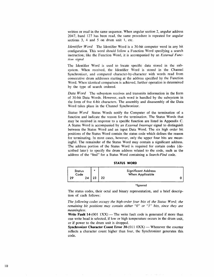
Status Word Status Words notify the Computer of the termination of a function and indicate the reason for the termination. The Status Words that may be received in response to a specific function are listed in Appendix C. A Status Word is accompanied by an External ] nterrupt signal to distinguish between the Status Word and an input Data Word. The six high order bit positions of the Status Word contain the status code which defines the reason for terminating. In most cases, however, only the upper four bits are meaningful. The remainder of the Status Word may contain a significant address. The address portion of the Status Word is required for certain codes (described later) to specify the drum address related to the code, such as the address of the "find" for a Status Word containing a Search-Find code.
STATUS WORD
Status * Significant Address Code When Applicable
29 24 23 22 0
*Ignored
The status codes, their octal and binary representation, and a brief description of each follows:
The following codes occupy the high-order four bits of the Status Word; the remaining bit positions may contain either "0" or "]" bits, since they are meaningless. Write Fault 14-(001 1XX) - The write fault code is generated if more than one write head is selected, if low or high temperature occurs in the drum unit, or if power to the drum unit is dropped. Synchronizer Character Count Error 30-(011 OXX) - Whenever the counter reflects a character count higher than four, the Synchronizer generates this code.
End of File 34-(011 1 XX) - The end of file code is generated when the next sequential address is an illegal address or an address on an inoperable drum and, therefore, can not be reached during the execution of a function. Normal Completion 40-( 1 00 OXX) - This code informs the Computer of normal completion of a Terminate function that requested an interrupt. Illegal Function 50-( 1 0 1 OXX) - The illegal function code is generated when the function code portion of the Function Word is not contained in the FH-880 Instruction Repertoire. Illegal Address 54-( 1 0 1 1 XX) - If the Function Word contained a nonexistent address, an address of an inoperable drum, or a bootstrap address for a Write function when the bootstrap area is locked out, a Status Word with the illegal address code is sent to the Computer. Control Unit Sequenre Error 60-( 11 0 OXX) - This code is generated when character timing pulses are not in synchronism with word mark timing. Continuous Read Parity Error 64-( 11 0 1 XX) - This code informs the Computer that a parity error occurred during a Continuous Read Function. The word containing the error is "held" in the Synchronizer and an Input Data Request signal will be sent to the Computer immediately following the acknowledgment of the interrupt. If the input buffer is active the word containing the parity error will be transferred to the Computer. Data transfer then stops. A Terminate function must be sent to restore the Channel Synchronizer to a ready condition. Control Unit Write Character Count Error 70-(111 OXX) - This code is generated during a write operation when one of the characters of a word is not received by the Control Unit in time to be recorded.
The codes that follow occupy the high-order six bits of the Status Word and all are accompanied by a significant address (2 22_2°). End of Block 04-(000 100) - The end of block code informs the Computer that an End-of-Block Word (all binary l's) has been read during a block function. The Status Word contains this code and the four least significant characters of the word (overflow word) following the End-of-Block Word. The low-order 23 bits of the overflow word could be programmed to contain the starting address of data related to the block just read. Search Find 05-(000 101) - The search find code informs the Computer that the specific word requested in the search function has been located. The low-order 23 bits of the Status Word contain the drum address of the "find." Overflow Parity Error 06-(000 110) - If a parity error occurs when reading the overflow word (word following an End-of-Block Word), this code is generated. The low-order 23 bits of the Status Word contain the drum address of the overflow word. Non-Continuous Read Parity Error and Character Count Error 07-(000 111) - This code informs the Computer that a parity error or character count error occurred during a non-continuous read function and also informs the Computer when a character count error occurs in the Control Unit during a continuous read function. The low-order 23 bits of the Status Word contain the drum address of the erroneous word.
Bootstrap One third (2048 addresses) of band 0 on drum unit 0 may be specified for bootstrap use. This is accomplished by positioning the BOOTsTRAp-WRITE switch located behind the front door of the Control Cabinet.
11
12
When the switch is in the ON position, recording can t~ke place in this area. If the switch is in the OFF position, writing in this area is inhibited to prevent unintentional destruction of previously recorded data. When the switch is in the OFF position and a Write Function Word is received specifying an address in the bootstrap area, the subsystem generates the Illegal Address (54) status code. There are two Bootstrap Instructions in the FH-880 repertoire: Bootstrap wiih inierrupl and BOOlslrap wiThoUl imerrupt. Borh functions amomaIicaHy initiate a read from octal address 0 on drum unit 0 and ignore the address specified in the Function Word. Bootstrap with interrupt commands a Block Read; Bootstrap without interrupt commands a Continuous Read.
Typical Programming Examples of basic programming sequences are given in Appendix D. These show the format of Instruction Words, Buffer Control Words, Function Words, and Identifier Words within the Computer.
Programming Considerations Some of the characteristics that should be considered when programming an FH-880 Magnetic Drum Subsystem are:
1. End-of-Block words (all l's) during Continuous Read, Search Read and Write functions are handled in the same manner as other data words. During block functions the End-of-Block word is decoded before being transferred to the Computer.
2. If the Computer fails to transfer a word during a Write function, the subsystem is prepared to write at the specific address once each revolution of the drum. This continues until a word or a Terminate Function Word is received.
3. If the Computer fails to accept a word during a Read function, the word remains available in the subsystem until transferred or until a . Terminate Function Word is received from the Computer.
4. When writing in or reading from the last address in the subsystem, the word transfer is completed and then the subsystem generates an End-o/File (34) status code.
There are three caution points when programming Function Words:
1. If a Search function is sent to the subsystem and is followed by another Function Word, the second Function Word is assumed to be an Identifier Word and the search begins, using this word. If, for example, a Search function were followed by a Terminate Function Word, the Terminate Function Word would not be recognized as such and the subsystem would continue the search operation. Therefore, an Identifier Word should always be programmed to follow a Search function.
2. A Terminate Function Word must be programmed at the completion of the following functions: Write (02), Continuous Read (42), SeQrch Read (46), and Bootstrap 'Without I nturupt (40). The Write function must be termi1U!lted with interrupt.
3. If the condition of the channel is not known, a Terminate function should be issued to stop any operation the subsystem may be perfonning prior to issuing a Bootstrap or any other function.
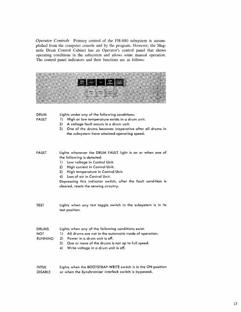
Operator Controls Primary control of the FH-880 subsystem i.s accomplished from the computer console and by the program. However, the Magnetic Drum Control Cabinet has an Operator's control panel that shows operating conditions in the subsystem and allows some manual operation. The control panel indicators and their functions are as follows:
DRUM FAULT
FAULT
lights under any of the following conditions: 1) High or low temperature exists in a drum unit. 2) A voltage fault occurs in a drum unit. 3) One of the drums becomes inoperative after all drums in
the subsystem have attained operating speed.
lights whenever the DRUM FAULT light is on or when one of the following is detected: 1) low voltage in Control Unit. 2) High current in Control Unit. 3) High temperature in Control Unit. 4) loss of air in Control Unit. Depressing this indicator switch, after the fault condition is cleared, resets the sensing circuitry.
TEST lights when any test toggle switch in the subsystem is in its test position.
DRUMS NOT RUNNING
INTlK DISABLE
lights when any of the folloWing conditions exist: 1) All drums are not in the automatic mode of operation.
2) Power in a drum unit is off. 3) One or more of the drums is not up to full speed. 4) Write voltage in a drum unit is off.
lights when the BOOTSTRAP-WRITE switch is in the ON position or when the Synchronizer interlock switch is bypassed.
13
14
DRUMS ON
DRUMS OFF
OFF SWITCH
Depressing this indicator/switch starts sequential operation of the drums. Logical drum unit 0 starts first and, once it is up to speed, the sequence continues until all drums are running. This indicator lights immediately; however, the DRUMS NOT RUNNING indicator remains on until all drums in the subsystem are up to speed.
Depressing this indicator/switch removes power from the drums and lights the indicator. This switch must be held until the DRUMS ON indicator goes out. Power to the Magnetic Drum Control Cabinet units is not affected.
Depressing this indicator switch removes power from the Magnetic Drum Control Cabinet units. Power on is indicated by green light; power off by red light.
LOGIC Storage Format and Control The information contained in this section, along with the basic addressing information in the Characteristics and Programming Sections, provides a more detailed knowledge of FH-880 storage techniques. The FH-880 storage format drawing on page 15 illustrates the descriptions that follow.
Data Section
Data is stored on the drum surface in angular sections (word sections). Each angular section provides storage for five 6-bit data characters (one 30-bit word). In each angular section the most significant character is recorded first, followed by the remaining four characters of the word.
Address Section
Pre-recorded addresses are written around the periphery of the drum in an address band. Each address section corresponds to one word section in each data band on the drum. There are 6,168 pre-recorded addresses on each drum. However, only 6,144 of the addresses are active; the remaining 24 are dead-address locations.
PRERECORDED ADDRESS
ANGULAR SECTION (WORD SECTION)
r"
23
211
....
2°
28
2°
}
ANGULAR ADDRESS
ANGULAR SECTION
15
16
Reading and writing is inhibited in the 24 dead-address locations in each band. The dead addresses provide time to switch from the tracks on the band just read or recorded to the tracks on the next band.
An address section contains four address characters. Each address section is positioned prior to its corresponding word section. This allows the Control Unit time to receive the complete address before reading or writing in the associated word se('tion.
Timing Section
The timing section comprises four active tracks: Single Mark, Reference Mark, Word Mark, and Timing. The timing section illustration on page 17 shows the relationship of the timing tracks and the address tracks. The function of each track is as follows: Timing Track - The timing track contains one mark for each character time. These timing pulses provide timing and control necessary to transfer data and address characters from the drum to the Control Unit. Word Mark Track - The word mark track contains one mark for each address location. This mark is coincident with the last character position of each address section. The word mark checks address coincidence and synchronizes the transfer of data to and from the drum. Reference Mark Track - This track contains one mark recorded four address character times before the first word mark. The reference mark indicates the "beginning" of the drum and clears the read-write lockout after passing the dead-address locations. Single Mark Track - This pulse is provided for synchronizing an oscilloscope when performing maintenance.
Parity Section
A parity bit is written to maintain odd parity for each word recorded. That is, a "1" bit is written whenever the word contains an even number of "1 's." Parity bits are recorded around the periphery of a drum on 32 tracks. Each parity section is considered as being divided into four groups of eight tracks with each track holding the parity bits for four different data bands. The illustration below shows the location of parity bits by band number for a particular angular address and angular section.
V-PARITY TRACK 0
o 1 2 3 4 5 6 7 32 33 8 9 10 11 12 13 14 15 40 41
16 17 18 19 20 21 22 23 48 49 24 25 26 27 28 29 30 31 56 57
PARITY TRACK 31----,t
} 70 71 96 97 98 99 100 101 102 103 78 79 104 105 106 107 108 109 110 111 86 87 112 113 114 115 116 117 118 119 94 95 120 121 122 123 124 125 126 127
Computer Output A simplified diagram of the FH-880 Magnetic Drum Subsystem is shown on page 18. The output data paths show the disassembly of computer words in the Channel Synchronizer, and the routing through the Drum Control Unit to a specific drum.
SINGLE MARK TRACK
REFERENCE MARK TRACK
1 1 1 1 I---+------I--~-I
1 I---+--+--I-~ 24 DEAD
1 1 :> ADDRESS
1 1 LOCATIONS
I---+------I--~-I
1 1---+---+-4.-_1
1 1
1
1 1
1
1
1-0+-...............
} AA 0
- AS 0 I---+-----+--I-~
1 I---+-----+-~......t
1 1 J-..... -+-.... ~ ...
1 I---+-----+-+.--_I
1
1
rILm III AAO ASI
> THROUGH AA2~7 ASI
NOTES:
AA = ANGULAR ADDRESS
AS = ANGULAR SECTION
A MARK (1) REPRESENTS A "1" BIT
NO MARK REPRESENTS A "0" BIT
SPARE TRACKS RECORDED:
REFERENCE MARK - 2
WORD MARK - 2
TIMING TRACK -2
ADDRESS TRACKS - 2 SETS OF 4
D4WW ROTATION
17
18
DRUM UNIT
PARITY CHECKER 8 GENERATOR ~----.....
DRUM CONTROL UNIT
SEARCH
COMPARISON
CONTROL
CHANNEL SVN CHRONlZER
COMPUTER
6
CHARACTER REGISTER
DRUM UNIT
NO.1
DRUM NO.1
DRUM BUFFER REGISTER
ADDRESS COMPARATOR
~--..... w WORD ADDRESS REGISTER
L.---....jal
6
CONTROL CHARACTER
REGISTER
FUNCTION REG.
8 DECODER
INTERRUPT CODE
REGISTER
4
STATUS CODE REGISTER
A 30-bit Function Word, Data Word, or Identifier Word is transmitted from the Computer to the Channel Synchronizer disassembly register. Then, as the character counter transmits control signals, each character is transferred. Function Word and Data Word characters are routed to the control character register in the Drum Control Unit. Routing from this point varies. In the case of an Identifier Word, the word is held in the disassembly register until identical comparison is achieved by the search- comparison control.
Function Word -If a Function Word has been received, the function code bits are routed to the function code register and decoder; the address designator bits are routed to the word address register. The output of the function decoder through various control circuits conditions the Control Unit for the desired operation. The 23 bits held in the word address register determine the starting point for the operation. The outputs of decoders associated with the angular section and channel portion of the word address register are sent to each drum in the subsystem to select a particular drum. The content of the angular address portion is then compared with the addresses read from the selected drum until identical comparison is achieved. The requested function starts at this address.
Data Word - Data Word characters are routed from the control character register to the drum buffer register. Each 6-bit character is held in the drum buffer register until the desired address is reached and then the character is written on the drum. The characters passing through the drum buffer register are checked by the parity checker and generator. After five characters (one word) have been received, the appropriate parity bit (to maintain odd parity) is transferred to the drum by the parity generator.
Computer Input The input data paths, illustrated in the diagram, show the routing for 6-bit word segments from a drum via the Drum Control Unit to the assembly register in the Channel Synchronizer.
When a Read or Search function has been requested and the first word to be read from the drum has been reached, each 6-bit character read from the drum is transferred to the drum buffer register.
Parity is checked by the parity checker and generator as the five 6-bit characters pass through the drum buffer register. When the parity checker receives the parity bit, following the last character of each word, the parity status of the 30-bit word is determined. If a parity error occurred, the control circuitry is notified.
Each 6-bit character is transferred from the drum buffer register to the character register in the Channel Synchronizer. Routing from the character register differs for the search and read portions of a Computer input operation.
Search - During a Search function, each character is routed to the search comparison control to be compared with the corresponding character of the Identifier Word stored in the disassembly register. When a "find" (identical word comparison) is made, further operation is determined by the type of search ordered.
19
20
Read - During Read functions, each character from the character register is gated into its corresponding portion of the assembly register until the complete word is assembled. The 30-bit word is held in the assembly register until acknowledged by the Computer. In the case of a Status Word transfer, the four high-order bits are transferred to the Computer directly from the status code register in the Channel Synchronizer. When a six-bit status code is transferred, bit positions 225 and 224 are transferred from the interrupt code register in the Control Unit, via the assembly register, to the Computer.
APPENDIX A.
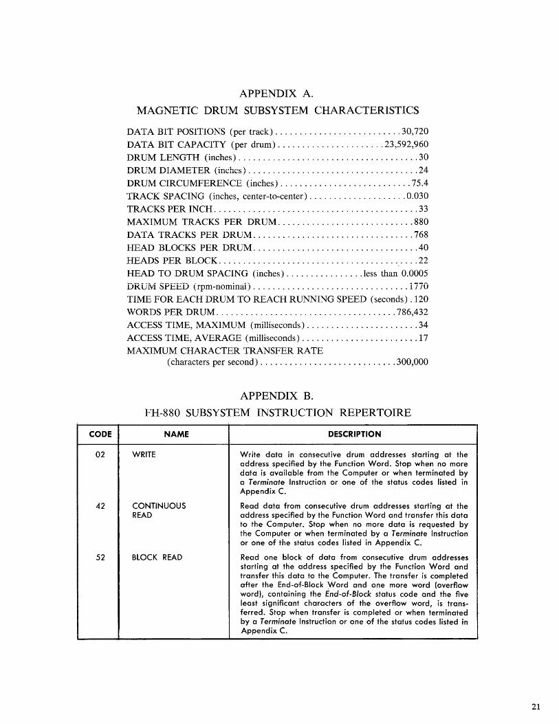
MAGNETIC DRUM SUBSYSTEM CHARACTERISTICS
DATA BIT POSITIONS (per track) .......................... 30,720
DATA BIT CAPACITY (per drum) ...................... 23,592,960 DRUM LENGTH (inches) ..................................... 30 DRUM DIAMETER (inches) ................................... 24
DRUM CIRCUMFERENCE (inches) ........................... 75.4 TRACK SPACING (inches, center-to-center) .................... 0.030
TRACKS PER INCH .......................................... 33 MAXIMUM TRACKS PER DRUM ............................ 880 DATA TRACKS PER DRUM ................................. 768
HEAD BLOCKS PER DRUM .................................. 40 HEADS PER BLOCK ......................................... 22
HEAD TO DRUM SPACING (inches) ................ less than 0.0005 DRUM SPEED (rpm-nominal) ................................ 1770 TIME FOR EACH DRUM TO REACH RUNNING SPEED (seconds) .120
WORDS PER DRUM ..................................... 786,432 ACCESS TIME, MAXIMUM (milliseconds) ....................... 34 ACCESS TIME, AVERAGE (milliseconds) ........................ 17
MAXIMUM CHARACTER TRANSFER RATE (characters per second) ............................ 300,000
APPENDIX B.
FH-880 SUBSYSTEM INSTRUCTION REPERTOIRE
CODE NAME DESCRIPTION
02 WRITE Write data in consecutive drum addresses starting at the address specified by the Function Word. Stop when no more data is available from the Computer or when terminated by a Terminate Instruction or one of the status codes listed in Appendix C.
42 CONTINUOUS Read data from consecutive drum addresses starting at the READ address specified by the Function Word and transfer this data
to the Computer. Stop when no more data is requested by the Computer or when terminated by a Terminate Instruction or one of the status codes listed in Appendix C.
52 BLOCK READ Read one block of data from consecutive drum addresses starting at the address specified by the Function Word and transfer this data to the Computer. The transfer is completed after the End-of-Block Word and one more word (overflow word), containing the End-of-Block status code and the five least significant characters of the overflow word, is trans-ferred. Stop when transfer is completed or when terminated by a Terminate Instruction or one of the status codes listed in Appendix C.
21
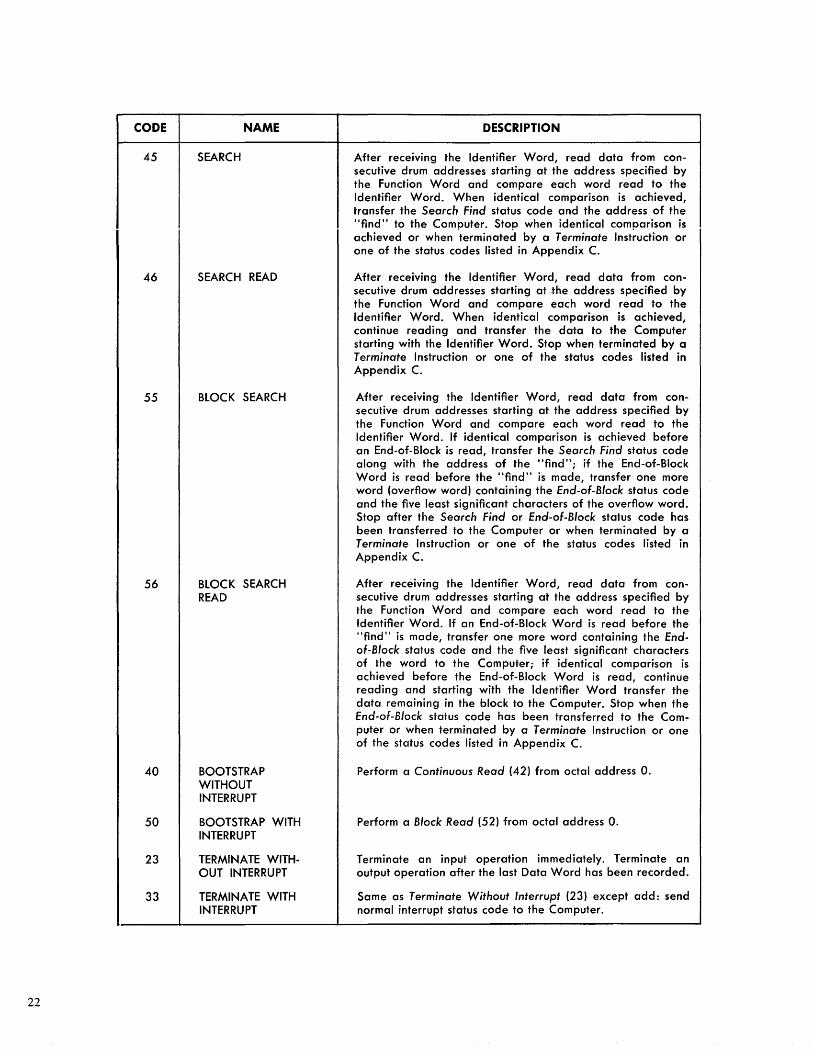
CODE
45
46
55
56
40
50
23
33
22
NAME
SEARCH
SEARCH READ
BLOCK SEARCH
BLOCK SEARCH READ
BOOTSTRAP WITHOUT INTERRUPT
BOOTSTRAP WITH INTERRUPT
TERMINATE WITHOUT INTERRUPT
TERMINATE WITH INTERRUPT
DESCRIPTION
After receiving the Identifier Word, read data from consecutive drum addresses starting at the address specified by the Function Word and compare each word read to the Identifier Word. When identical comparison is achieved, transfer the Search Find status code and the address of the "find" to the Computer. Stop when identical comparison is achieved or when terminated by a Terminate Instruction or one of the status codes listed in Appendix C.
After receiving the Identifier Word, read data from consecutive drum addresses starting at the address specified by the Function Word and compare each word read to the Identifier Word. When identical comparison is achieved, continue reading and transfer the data to the Computer starting with the Identifier Word. Stop when terminated by a Terminate Instruction or one of the status codes listed in Appendix C.
After receiving the Identifier Word, read data from consecutive drum addresses starting at the address specified by the Function Word and compare each word read to the Identifier Word. If identical comparison is achieved before an End-of-Block is read, transfer the Search Find status code along with the address of the "find" j if the End-of-Block Word is read before the "find" is made, transfer one more word (overflow word) containing the End-oF-Block status code and the five least significant characters of the overflow word. Stop after the Search Find or End-oF-Block status code has been transferred to the Computer or when terminated by a Terminate Instruction or one of the status codes listed in Appendix C.
After receiving the Identifier Word, read data from consecutive drum addresses starting at the address specified by the Function Word and compare each word read to the Identifier Word. If an End-of-Block Word is read before the "find" is made, transfer one more word containing the Endof-Block status code and the five least significant characters of the word to the Computerj if identical comparison is achieved before the End-of-Block Word is read, continue reading and starting with the Identifier Word transfer the data remaining in the block to the Computer. Stop when the End-oF-Block status code has been transferred to the Computer or when terminated by a Terminate Instruction or one of the status codes listed in Appendix C.
Perform a Continuous Read (42) from octal address O.
Perform a Block Read (52) from octal address O.
Terminate an input operation immediately. Terminate an output operation after the last Data Word has been recorded.
Same as Terminate Without Interrupt (23) except add: send normal interrupt status code to the Computer.
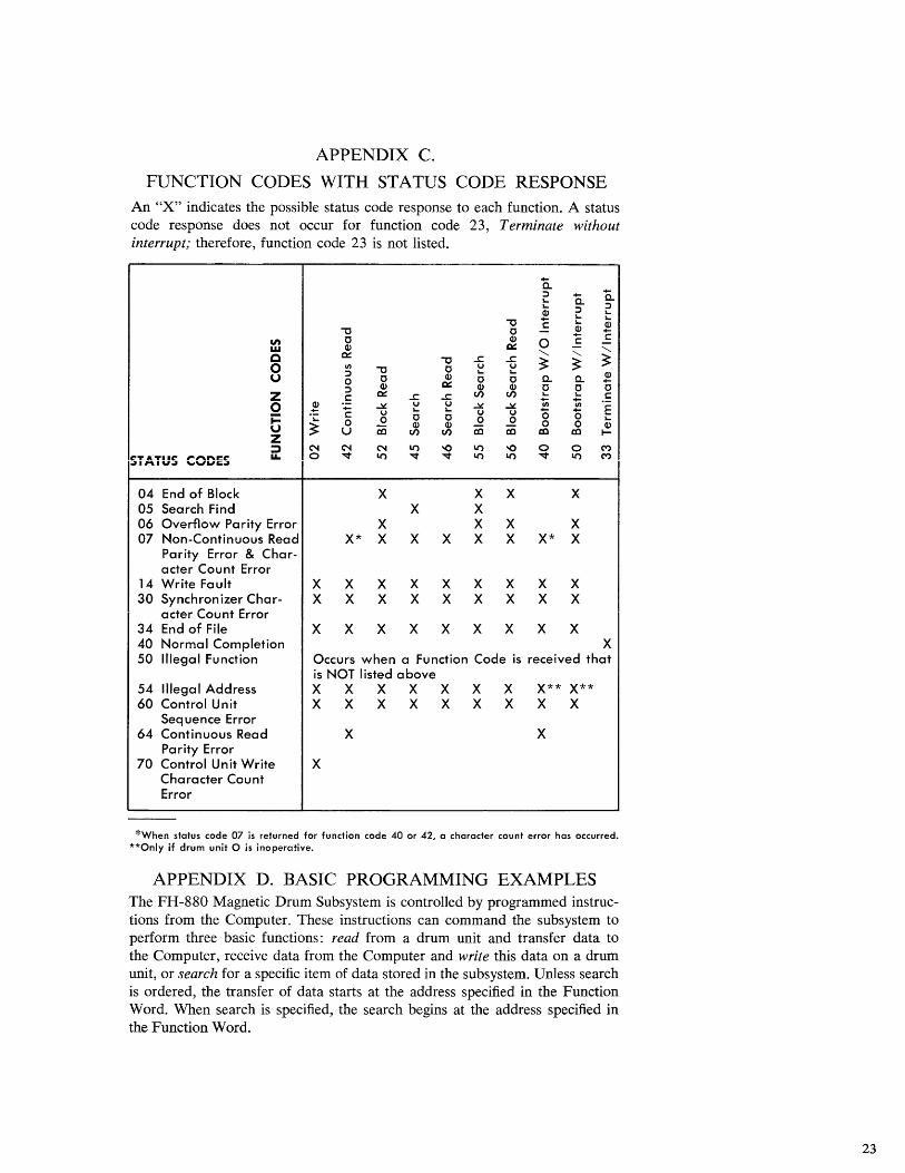
APPENDIX C.
FUNCTION CODES WITH ST A TUS CODE RESPONSE An "X" indicates the possible status code response to each function. A status code response does not occur for function code 23, Terminate without interrupt; therefore, function code 23 is not listed.
0.. :::> 0.. 0.. lo.... lo.... :::> :::> Q) lo....
C lo.... lo....
"'0 lo.... Q) "'0 0 - Q) c
'" 0 Q) 0 c -w Q) c::: - "'" c c::: "'" "'" ~ "'0 ....c ....c ~ ~ 0 CI)
"'0 0 u u :::> lo.... lo....
! u 0 0 Q) 0 0 a.. a.. :::> Q) c::: Q) Q) 0 0 0
z c:: c::: ....c ....c en en .;: .;: c:: 0 ! ..::,t, u u ..::,t, ..::,t, CI) CI)
E C U lo.... lo.... U u "0 "0 i= .;: ..Q 0 0 0 ..Q lo....
U ~ 0 Q) Q)
Ci5 0 0 Q)
z U a::I en en a::I a::I a::I I-
::J N N N Ii') -0 Ii') -0 0 0 C"')
STATUS CODES 1.1. 0 -.:::t Ii') -.:::t -.:::t Ii') Ii') -.:::t Ii') C"')
04 End of Block X X X X 05 Search Find X X 06 Overflow Parity Error X X X X 07 Non-Continuous Read X* X X X X X X* X
Parity Error & Char-acter Count Error
14 Write Fault X X X X X X X X X 30 Synchronizer Char- X X X X X X X X X
acter Count Error 34 End of File X X X X X X X X X 40 Normal Completion X 50 Illegal Function Occurs when a Function Code is received that
is NOT listed above 54 Illegal Address X X X X X X X X** X** 60 Control Unit X X X X X X X X X
Sequence Error 64 Continuous Read X X
Parity Error 70 Control Unit Write X
Character Count Error
*When status code 07 is returned for function code 40 or 42, a character count error has occurred. **Only if drum unit 0 is inoperative.
APPENDIX D. BASIC PROGRAMMING EXAMPLES The FH-880 Magnetic Drum Subsystem is controlled by programmed instructions from the Computer. These instructions can command the subsystem to perform three basic functions: read from a drum unit and transfer data to the Computer, receive data from the Computer and write this data on a drum unit, or search for a specific item of data stored in the subsystem. Unless search is ordered, the transfer of data starts at the address specified in the Function Word. When search is specified, the search begins at the address specified in the Function Word.
23
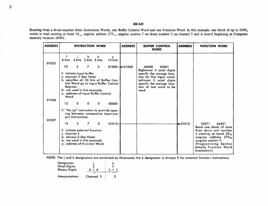
READ
Reading from a drum requires three Instruction Words, one Buffer Control Word and one Function Word. In this example, one block of up to 20008
words is read starting at band 2910' angular address 2731°' angular section 7 on drum number 2 on channelS and is stored beginning at Computer memory location 20001.
ADDRESS
01025
01026
01027
INSTRUCTION WORD
f i k b 6 bits 4 bits 2 bits 3 bits
Y 15 bits
ADDRESS
73 2 7 o 01 000- ~01 000
f: initiate input buffer j: channel 5 (See Note) k: specifies all 30 bits of Buffer Con
trol Word go to Input Buffer Control Register.
b: not used in this example. y: address of Input Buffer Control
Word
12 o o o 00000
f: "No op" instruction to provide spacing between consecutive input-output instructions.
BUFFER CONTROL WORD
40000 20001 Rightmost 5 octal digits specify the storage location for first input word. Leftmost 5 octa I dig its specify the storage location of last word to be read.
ADDRESS
13 2 7 o 01010~-------r------------------~I"r01010
f: initiate external function i: channel 5 k: always 3 (See Note) b: not used in this example y: address of Function Word
FUNCTION WORD
52071 64421 Read one block of data from drum unit number 2 startin~1 at band 29101
angular address 273 101 angular section 7. (Programming Section details Function Word breakdown)
NOTE: The i and k designators are combined as illustrated; the k designator is always 3 for external functiol1 instructions.
Designator: i k Octal Digits: 2 7 Binary Digits ~,-0_---r----,1/ ~
Interpretation: Channel 5 3
N VI
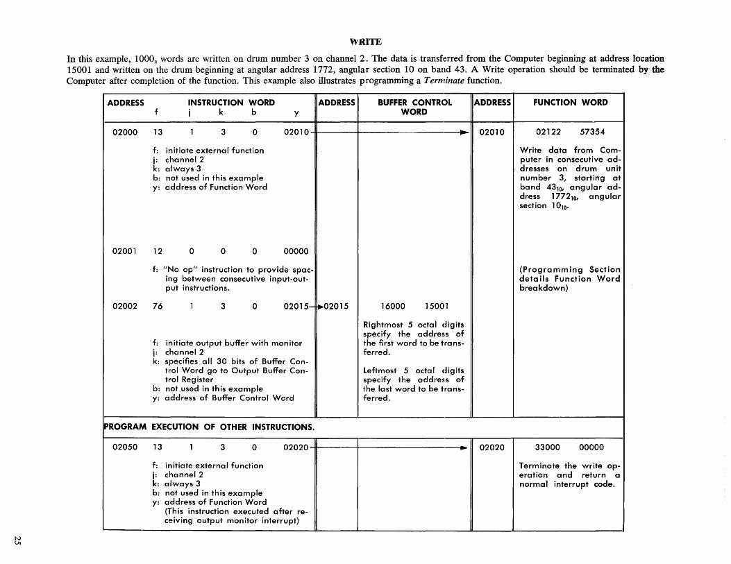
WRITE
In this example, 10008 words are written on drum number 3 on channel 2. The data is transferred from the Computer beginning at address location 15001 and written on the drum beginning at angular address 1772, angular section 10 on band 43. A Write operation should be terminated by the Computer after completion of the function. This example also illustrates programming a Terminate function.
ADDRESS INSTRUCTION WORD ADDRESS BUFFER CONTROL ADDRESS FUNCTION WORD f j k b y WORD
02000 13 1 3 0 02010 --.... 02010 02122 57354
f: initiate external function Write data from Com-j: channel 2 puter in consecutive ad-k: always 3 dresses on drum unit b: not used in this example number 3, starting at y: address of Function Word band 4310, angular ad-
dress 17721°' angular section 101o.
02001 12 0 0 0 00000
f: "No Op" instruction to provide spac- (Programming Section ing between consecutive input-out- details Function Word put instructions. breakdown)
02002 76 1 3 0 02015- ~02015 16000 15001
Rightmost 5 octal digits specify the address of
f: initiate output buffer with monitor the first word to be trans-j: channel 2 ferred. k: specifies all 30 bits of Buffer Con-
trol Word go to Output Buffer Con- Leftmost 5 octal digits trol Reg ister specify the addres,s of
b: not used in this example the last word to be trans-y: address of Buffer Control Word ferred.
PROGRAM EXECUTION OF OTHER INSTRUCTIONS.
02050 13 1 3 0 02020 ---.. 02020 33000 00000
f: initiate external function Terminate the write op-j: channel 2 eration and return a k: always 3 normal interrupt code. b: not used in this example y: address of Function Word
(This instruction executed after re-ceiving output monitor interrupt)
N 0\
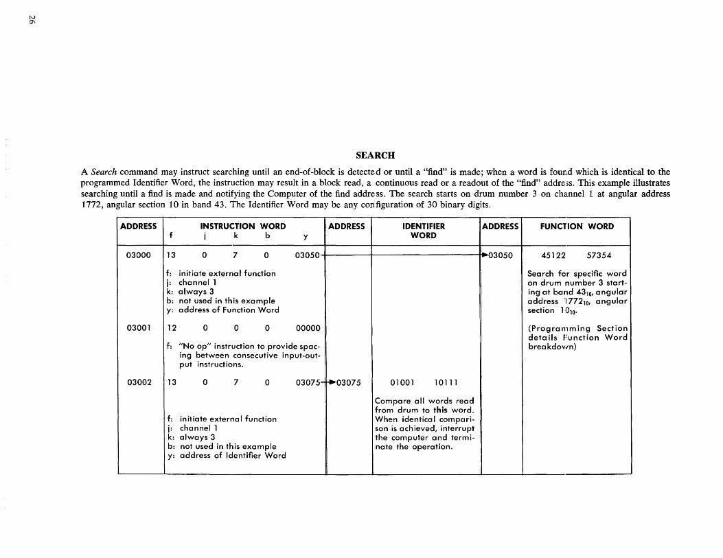
SEARCH
A Search command may instruct searching until an end-of-block is detected or until a "find" is made; when a word is found which is identical to the programmed Identifier Word, the instruction may result in a block read, a continuous read or a readout of the "find" address. This example illustrates searching until a find is made and notifying the Computer of the find addre ss. The search starts on drum number 3 on channel 1 at angular address 1772, angular section 10 in band 43, The Identifier Word may be any configuration of 30 binary digits.
ADDRESS INSTRUCTION WORD ADDRESS IDENTIFIER ADDRESS FUNC1'ION WORD f j k b y WORD
03000 13 0 7 0 03050 03050 45122 57354
f: initiate external function Search for specific word j: channell on drum number 3 start-k: always 3 ing at band 4310, angular b: not used in this example address '177210, angular y: address of Function Word section 1010,
03001 12 0 0 0 00000 (Programming Section details Function Word
f: "No Opll instruction to provide spac- breakdown) ing between consecutive input-out-put instructions.
03002 13 0 7 0 03075- ~03075 01001 10111
Compare all words read from drum to this word.
f: initiate externa I function When identical compari-j: channell son is achieved, interrupt k: always 3 the computer and termi-b: not used in this example nate the operation. y: address of Identifier Word
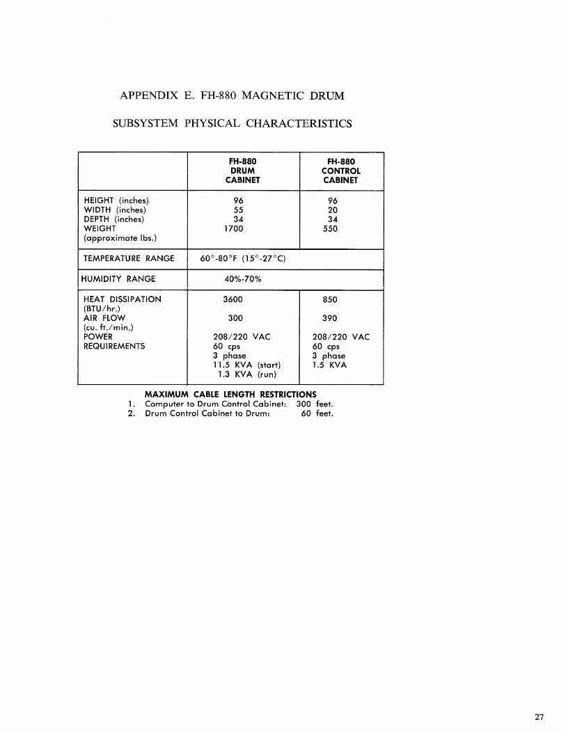
APPENDIX E. FH-880 MAGNETIC DRUM
SUBSYSTEM PHYSICAL CHARACTERISTICS
FH-880 FH-880 DRUM CONTROL
CABINET CABINET
HEIGHT (inches) 96 96 WIDTH (inches) 55 20 DEPTH (inches) 34 34 WEIGHT 1700 550 (approximate Ibs.)
TEMPERATU RE RANGE 60°-80°F (l5°-27°C)
HUMIDITY RANGE 40%-70%
HEAT DISSIPATION 3600 850 (BTU/hr.) AIR flOW 300 390 (cu. ft.lmin.) POWER 208/220 VAC 208/220 VAC REQU I REMENTS 60 cps 60 cps
3 phase 3 phase 11.5 KVA (start) 1.5 KVA
1.3 KV A (run)
MAXIMUM CABLE LENGTH RESTRICTIONS 1. Computer to Drum Control Cabinet: 300 feet. 2. Drum Control Cabinet to Drum: 60 feet.
27

UNIVAC
1'1>'~NT£o UT 2474 REV. 1 MARCH, 1963 us.--