chapter 12: attitude instrument flying · magnetic compass the magnetic compass is one of the basic...
TRANSCRIPT
12-1
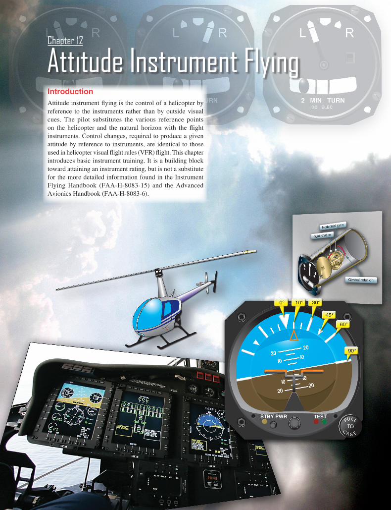
IntroductionAttitude instrument flying is the control of a helicopter by reference to the instruments rather than by outside visual cues. The pilot substitutes the various reference points on the helicopter and the natural horizon with the flight instruments. Control changes, required to produce a given attitude by reference to instruments, are identical to those used in helicopter visual flight rules (VFR) flight. This chapter introduces basic instrument training. It is a building block toward attaining an instrument rating, but is not a substitute for the more detailed information found in the Instrument Flying Handbook (FAA-H-8083-15) and the Advanced Avionics Handbook (FAA-H-8083-6).
Attitude Instrument FlyingChapter 12
12-2
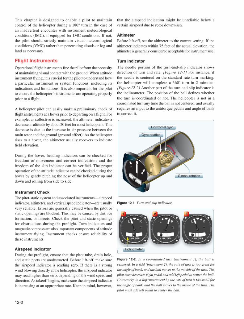
Gimbal rotation
Horizontal gyro
Gyro rotation
Figure 12-1. Turn-and-slip indicator.
2 MIN TURNDC ELEC
L R
2 MIN TURNDC ELEC
L R
2 MIN TURNDC ELEC
L R
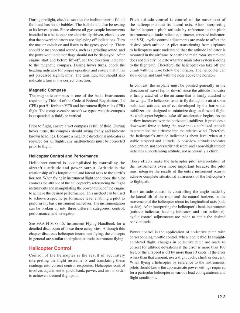
Inclinometer
1 2 3
Figure 12-2. In a coordinated turn (instrument 1), the ball is centered. In a skid (instrument 2), the rate of turn is too great for the angle of bank, and the ball moves to the outside of the turn. The pilot must decrease right pedal and add left pedal to center the ball. Conversely, in a slip (instrument 3), the rate of turn is too small for the angle of bank, and the ball moves to the inside of the turn. The pilot must add left pedal to center the ball.
This chapter is designed to enable a pilot to maintain control of the helicopter during a 180° turn in the case of an inadvertent encounter with instrument meteorological conditions (IMC). if equipped for IMC conditions. If not, the pilot should strictly maintain visual meteorological conditions (VMC) rather than penetrating clouds or fog and land as necessary.
Flight InstrumentsOperational flight instruments free the pilot from the necessity of maintaining visual contact with the ground. When attitude instrument flying, it is crucial for the pilot to understand how a particular instrument or system functions, including its indications and limitations. It is also important for the pilot to ensure the helicopter’s instruments are operating properly prior to a flight.
A helicopter pilot can easily make a preliminary check of flight instruments at a hover prior to departing on a flight. For example, as collective is increased, the altimeter indicates a decrease in altitude by about 20 feet for most helicopters. This decrease is due to the increase in air pressure between the main rotor and the ground (ground effect). As the helicopter rises to a hover, the altimeter usually recovers to indicate field elevation.
During the hover, heading indicators can be checked for freedom of movement and correct indications and the freedom of the slip indicator can be verified. The proper operation of the attitude indicator can be checked during the hover by gently pitching the nose of the helicopter up and down and rolling from side to side.
Instrument Check The pitot-static system and associated instruments—airspeed indicator, altimeter, and vertical speed indicator—are usually very reliable. Errors are generally caused when the pitot or static openings are blocked. This may be caused by dirt, ice formation, or insects. Check the pitot and static openings for obstructions during the preflight. Turn indicators and magnetic compass are also important components of attitude instrument flying. Instrument checks ensure reliability of these instruments.
Airspeed Indicator During the preflight, ensure that the pitot tube, drain hole, and static ports are unobstructed. Before lift-off, make sure the airspeed indicator is reading zero. If there is a strong wind blowing directly at the helicopter, the airspeed indicator may read higher than zero, depending on the wind speed and direction. As takeoff begins, make sure the airspeed indicator is increasing at an appropriate rate. Keep in mind, however,
that the airspeed indication might be unreliable below a certain airspeed due to rotor downwash.
AltimeterBefore lift-off, set the altimeter to the current setting. If the altimeter indicates within 75 feet of the actual elevation, the altimeter is generally considered acceptable for instrument use.
Turn IndicatorThe needle portion of the turn-and-slip indicator shows direction of turn and rate. [Figure 12-1] For instance, if the needle is centered on the standard rate turn marking, the helicopter will complete a 360˚ turn in 2 minutes. [Figure 12-2] Another part of the turn-and-slip indicator is the inclinometer. The position of the ball defines whether the turn is coordinated or not. The helicopter is not in a coordinated turn any time the ball is not centered, and usually requires an input to the antitorque pedals and angle of bank to correct it.
12-3
During preflight, check to see that the inclinometer is full of fluid and has no air bubbles. The ball should also be resting at its lowest point. Since almost all gyroscopic instruments installed in a helicopter are electrically driven, check to see that the power indicators are displaying off indications. Turn the master switch on and listen to the gyros spool up. There should be no abnormal sounds, such as a grinding sound, and the power-out indicator flags should not be displayed. After engine start and before lift-off, set the direction indicator to the magnetic compass. During hover turns, check the heading indicator for proper operation and ensure that it has not precessed significantly. The turn indicator should also indicate a turn in the correct direction.
Magnetic CompassThe magnetic compass is one of the basic instruments required by Title 14 of the Code of Federal Regulations (14 CFR) part 91 for both VFR and instrument flight rules (IFR) flight. The compass can be one of two types: wet (the compass is suspended in fluid) or vertical.
Prior to flight, ensure a wet compass is full of fluid. During hover turns, the compass should swing freely and indicate known headings. Because a magnetic directional indicator is required for all flights, any malfunctions must be corrected prior to flight.
Helicopter Control and Performance
Helicopter control is accomplished by controlling the aircraft’s attitude and power output. Attitude is the relationship of its longitudinal and lateral axes to the earth’s horizon. When flying in instrument flight conditions, the pilot controls the attitude of the helicopter by referencing the flight instruments and manipulating the power output of the engine to achieve the desired performance. This method can be used to achieve a specific performance level enabling a pilot to perform any basic instrument maneuver. The instrumentation can be broken up into three different categories: control, performance, and navigation.
See FAA-H-8083-15, Instrument Flying Handbook for a detailed discussion of these three categories. Although this chapter discusses helicopter instrument flying, the concepts in general are similar to airplane attitude instrument flying.
Helicopter ControlControl of the helicopter is the result of accurately interpreting the flight instruments and translating these readings into correct control responses. Helicopter control involves adjustment to pitch, bank, power, and trim in order to achieve a desired flightpath.
Pitch attitude control is control of the movement of the helicopter about its lateral axis. After interpreting the helicopter’s pitch attitude by reference to the pitch instruments (attitude indicator, altimeter, airspeed indicator, and VSI), cyclic control adjustments are made to affect the desired pitch attitude. A pilot transitioning from airplanes to helicopters must understand that the attitude indicator is mounted in the airframe beneath the main rotor system and does not directly indicate what the main rotor system is doing to the flightpath. Therefore, the helicopter can take off and climb with the nose below the horizon. The helicopter can slow down and land with the nose above the horizon.
In contrast, the airplane must be pointed generally in the direction of travel (up or down) since the attitude indicator is firmly attached to the airframe that is firmly attached to the wings. The helicopter tends to fly through the air at some stabilized attitude, an effect developed by the horizontal stabilizer and designed to minimize drag in forward flight. As a helicopter begins to take off, acceleration begins. As the airflow increases over the horizontal stabilizer, it produces a downward force to bring the nose into a stabilized attitude to streamline the airframe into the relative wind. Therefore, the helicopter’s attitude indicator is about level when at a stable airspeed and altitude. A nose-low attitude indicates acceleration, not necessarily a descent, and a nose-high attitude indicates a decelerating attitude, not necessarily a climb.
These effects make the helicopter pilot interpretation of the instruments even more important because the pilot must integrate the results of the entire instrument scan to achieve complete situational awareness of the helicopter’s to flightpath.
Bank attitude control is controlling the angle made by the lateral tilt of the rotor and the natural horizon, or the movement of the helicopter about its longitudinal axis (side to side). After interpreting the helicopter’s bank instruments (attitude indicator, heading indicator, and turn indicator), cyclic control adjustments are made to attain the desired bank attitude.
Power control is the application of collective pitch with corresponding throttle control, where applicable. In straight-and-level flight, changes in collective pitch are made to correct for altitude deviations if the error is more than 100 feet, or the airspeed is off by more than 10 knots. If the error is less than that amount, use a slight cyclic climb or descent. When flying a helicopter by reference to the instruments, pilots should know the approximate power settings required for a particular helicopter in various load configurations and flight conditions.
12-4
Force or cyclic trim, in helicopters, refers to the use of the cyclic centering button, if the helicopter is so equipped, to relieve cyclic pressures. Trim also refers to the use of pedal adjustment to center the ball of the turn indicator. Pedal trim is required during all power changes.
The proper adjustment of collective pitch and cyclic friction helps pilots relax during instrument flight. Friction may be adjusted to minimize overcontrolling and to prevent creeping, but not applied to such a degree that control movement is limited. In addition, many helicopters equipped for instrument flight contain stability augmentation systems or an autopilot to help relieve pilot workload.
See FAA-H-8083-15, Instrument Flying Handbook, for a detailed explanation and illustrations concerning helicopter attitude instrument flying.
Common Errors of Attitude Instrument FlyingFixationFixation, or staring at one instrument, is a common error observed in pilots first learning to utilize instruments. The pilot may initially fixate on an instrument and make adjustments with reference to that instrument alone.
OmissionAnother common error associated with attitude instrument flying is omission of an instrument from the cross-check. Pilots tend to omit the stand-by instruments, as well as the magnetic compass from their scans. The position of the instrument is often the reason for the omission. One of the most commonly omitted instruments from the scan is the slip/skid indicator.
EmphasisIn initial training, placing emphasis on a single instrument is very common and can become a habit if not corrected. When the importance of a single instrument is elevated above another, the pilot begins to rely solely on that instrument for guidance. When rolling out of a 180° turn, the attitude indicator, heading indicator, slip/skid indicator, and altimeter need to be referenced. If a pilot omits the slip/skid indicator, coordination is sacrificed.
Inadvertent Entry into IMCPrior to any flight, day or night, an inadvertent IMC plan should be carefully planned and, if possible, rehearsed. Many aircraft mishaps can be blamed on the pilot’s inability to recover an aircraft after inadvertently entering IMC. The desire to stay outside visually is very strong and can only be overcome through training. IMC-trained helicopter pilots should climb to a safe altitude free of obstacles and obtain an
instrument clearance from ATC. However, for the nonrated pilot and, more importantly, a non-IFR equipped helicopter, remaining VMC is critical. Pilots who are not trained in IMC have a tendency to try and chase favorable weather by flying just above the tree tops or following roads. The thought process is that as long as they can see what is below them, then they can fly to their intended destination. Experience shows us that continuing VFR flight in IMC is often fatal. Pilots get too fixated on what they see below them and fail to see what is ahead of them, such as power lines, towers, and taller trees. By the time the pilot sees the obstacle, it is too close to avoid collision. Helicopter pilots should always remain aware of flight visibility by comparing how much can be seen ahead. As soon as the pilot notices a marked decrease in visibility, that pilot must reevaluate the flight plan and landing options. A suitable landing area can always be used to sit out bad weather and let conditions improve.
When planning for a night flight, pilots should carefully plan the flight over navigable routes with sufficient check points to ensure clearance from obstructions. Descents should be planned over known and easily identifiable areas. Deteriorating weather is even harder to detect at night; therefore, pilots should constantly evaluate the weather throughout the flight. Below are some basic steps to help the pilot remain in VMC throughout the flight.
1. Come to a hover if able or begin very slow flight just above translational lift speeds and land at the nearest safe area.
2. Slowly turn around and proceed back to VMC weather or first safe landing area if the weather ahead becomes questionable.
3. Do not proceed further on a course when the terrain ahead is not clearly discernable.
4. Always have a safe landing area in mind for every flight and always be aware of the safe landing area’s location.
5. Study the route whenever possible before flying it and ensure to stay on course throughout the flight.
There are five basic steps that every pilot should be ultimately familiar with and should be executed immediately after inadvertently entering IMC.
1. Attitude—level the wings on the attitude indicator, both pitch and bank.
2. Heading—pick a heading that is known to be free of obstacles and maintain it. This may be 180° from your current heading.
3. Power—adjust to a climb power setting.
4. Airspeed—adjust to a climb airspeed.
12-5
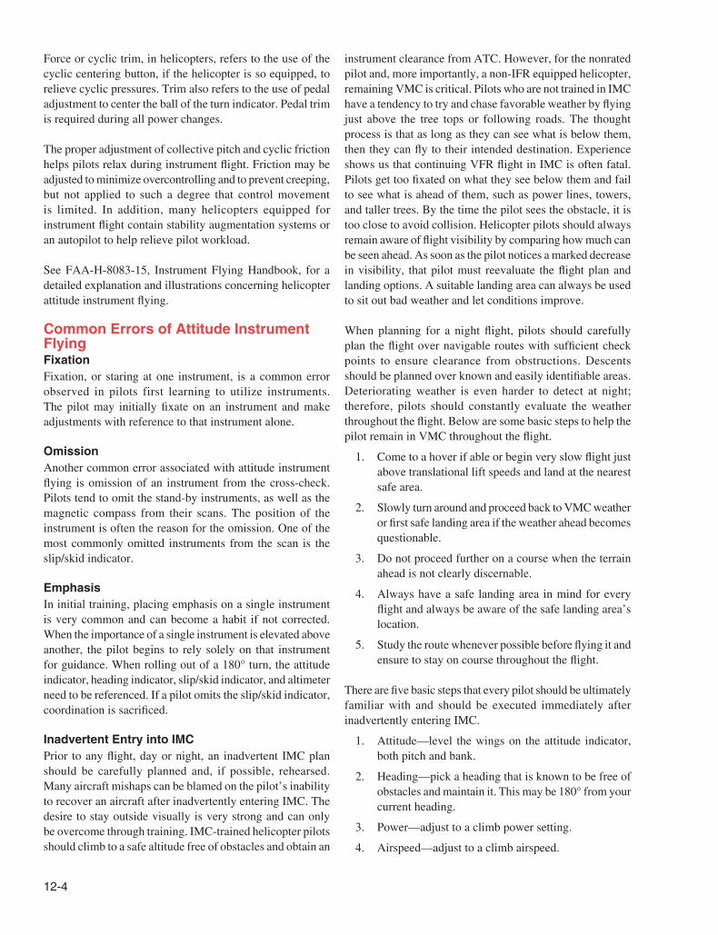
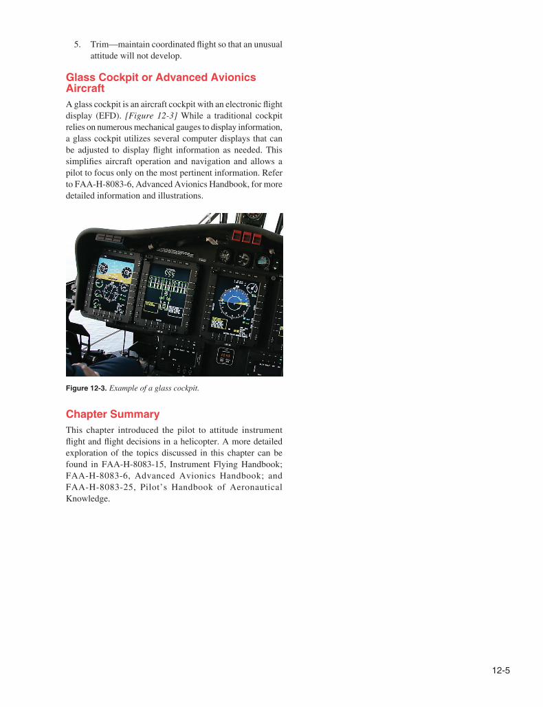
Figure 12-3. Example of a glass cockpit.
5. Trim—maintain coordinated flight so that an unusual attitude will not develop.
Glass Cockpit or Advanced Avionics AircraftA glass cockpit is an aircraft cockpit with an electronic flight display (EFD). [Figure 12-3] While a traditional cockpit relies on numerous mechanical gauges to display information, a glass cockpit utilizes several computer displays that can be adjusted to display flight information as needed. This simplifies aircraft operation and navigation and allows a pilot to focus only on the most pertinent information. Refer to FAA-H-8083-6, Advanced Avionics Handbook, for more detailed information and illustrations.
Chapter SummaryThis chapter introduced the pilot to attitude instrument flight and flight decisions in a helicopter. A more detailed exploration of the topics discussed in this chapter can be found in FAA-H-8083-15, Instrument Flying Handbook; FAA-H-8083-6, Advanced Avionics Handbook; and FAA-H-8083-25, Pilot’s Handbook of Aeronautical Knowledge.

12-6