flyback continuous mode – planar transformer design
TRANSCRIPT

Flyback Continuous mode – Planar Transformer Design Tutorial
An Industry Session at APEC 2020
Jim MarinosPayton America Inc.
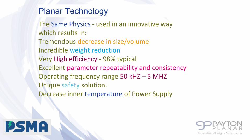
The Same Physics - used in an innovative way which results in:Tremendous decrease in size/volume Incredible weight reduction Very High efficiency - 98% typicalExcellent parameter repeatability and consistencyOperating frequency range 50 kHZ – 5 MHZUnique safety solution.Decrease inner temperature of Power Supply
Planar Technology

• High power density• High reliability solution• Consistency & Parameter Repeatability• Easy to cool - Flat shape connected to a heat-sink• High efficiency• Ease of handling high current, up-to 1000A
Advantages of the Planar Technology
3

Basic materials are copper, insulators, cores and bobbins
•Copper stampings from 0.2-1mm is used for high current winding. Results in low losses, good thermal conductivity and perfect for high frequency
•ML PCB, up to 20 layers, up to 6oz copper (mostly 3). Allow high number of turns, PCB reliable technology and production stability
Planar Technology basic materials

•Double side pcb, Used as base plates and for low current application. same advantages as the ML.
• Insulators- Mostly stamped Polyimide and Nomex depends on the insulation requirements.
These materials allow consistent production between lots and high reliability products.
Planar Technology basic materials

Ferrite
Conductors
Insulators
Ferrite
Bobbin (Optional)
Planar
Planar Transformer Structure
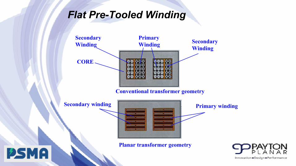
Flat Pre-Tooled Winding
Secondary Winding
PrimaryWinding Secondary
Winding
CORE
Secondary winding
Conventional transformer geometry
Planar transformer geometry
Primary winding

Proposed Specifications:
Pout=100 WattsVo=5VIout=20AF=200kHzInput=18-36VdcTamb= -55C to +80CTsurface=90CTopology=Continuous Flyback

Current Waveforms of a Continuous Flyback

Turns Ratio Calculation
Set Dmax at .65


One gauss is defined as one maxwell per square centimeter. The cgs system has been superseded by the International System of Units (SI), which uses the tesla (symbol T) as the unit of magnetic flux density. One gauss equals 1×10⁻⁴ tesla (100 μT), so 1 tesla = 10,000 gauss.


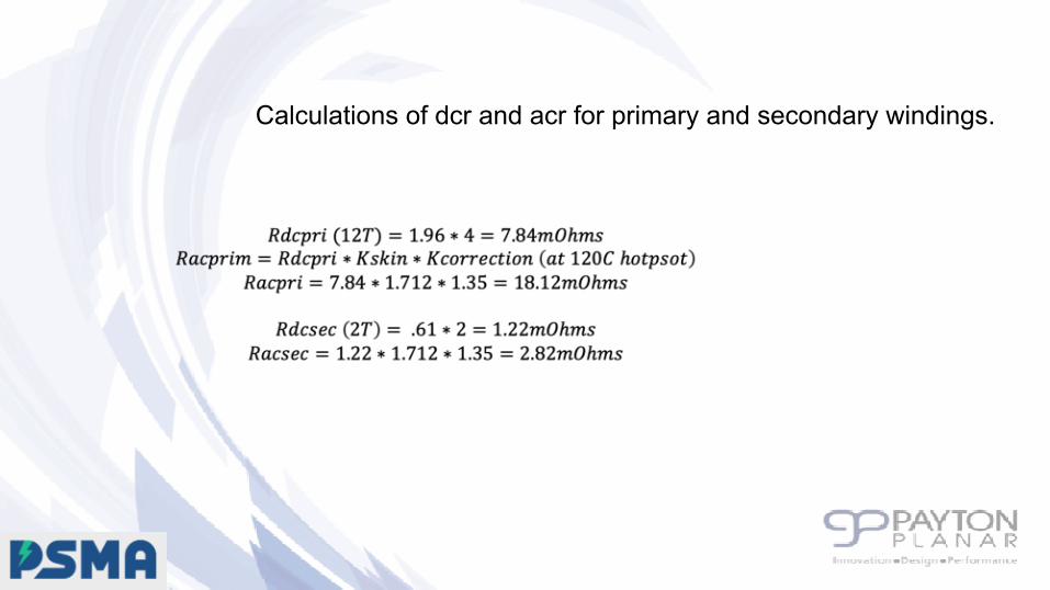
Calculations of dcr and acr for primary and secondary windings.

Skin depth in copper
Frequency Skin depth (μm)
50 Hz 9220
60 Hz 8420
10 kHz 652
100 kHz 206
1 MHz 65.2
10 MHz 20.6
100 MHz 6.52
1 GHz 2.06
Skin depth is due to the circulating eddy currents (arising from a changing H field) cancelling the current flow in the center of a conductor and reinforcing it in the skin.
Skin depth is due to the circulating eddy currents (arising from a changing H field) cancelling the current flow in the center of a conductor and reinforcing it in the skin.
Info taken from Wikipedia

In a conductor carrying switching current, if currents are flowing through one or more other nearby conductors, such as within a closely wound coil of wire, the distribution of current within the first conductor will be constrained to smaller regions. The resulting current current crowding is termed the proximity effect. This crowding gives an increase in the effective resistance of the circuit, which increases with frequency.
Excellent reference:

Copper Losses

