flow assurance work process - snu open courseware
TRANSCRIPT

Flow Assurance
서유택

Wax

Wax
• Paraffinic hydrocarbons
: A solid paraffinic hydrocarbon which precipitate from a produced fluid
: Forms when the fluid temperature drops below the Wax Appearance
Temperature (WAT)
: Melts at elevated temperature (20oF above the WAT)
• Control strategy
: Rate of deposition can be predicted to calculate pigging frequency
: Flowline insulation
: Wax inhibitor
: Major factors
- WAT
- Fluid temperature
- Overall U-value
- Deposition rate

• WAT or cloud point
: The temperature at which crystals first begin to form is called the
cloud point or wax appearance temperature (WAT)
: Crystals may form either in the bulk fluid, forming particles that are
transported along with the fluid, or deposit on a cold surface where
the crystals will build up and foul the surface.
: WAT does not indicate the amount of wax that will be deposited or
the rate at which it will be deposited.

• Pour point
: The pour point temperature is the temperature at which the oil stops
flowing and solidify into a gel.
: A crude oil gel forms when wax precipitates from the oil and forms a
3D structure spanning the pipe.
: This does not occur while the oil is flowing because the
intermolecular structure is destroyed by shear forces. However,
when the oil stops flowing, wax particles will interact, join together,
and form a network resulting in a gel structure if enough wax is out of
solution.

WAT determination
• The wax appearance temperature (WAT) or cloud point is the
most important parameter relating to wax formation.
CPM - Cross Polarized Microscopy
NIR - Near Infra Red Absorption Reflection
DSC - Differential Scanning Calorimetry
Cold Finger
Filtration
• WAT is a crystallization temperature and therefore kinetics will
influence any measurement. Thus, it is strongly recommended
that cloud point be determined using two different techniques.
With care, the cloud point can be determined to an accuracy of
5 oF.

WAT by Cross Polar Microscopy

• Thermodynamic models can predict wax appearance
Temperature (WAT) with
- Detailed compositional analysis of oil
- Quantitative n-paraffin analysis using high temperature
(HTGC technique, C90+)
• The thermodynamic model may be combined with the model of
flowline using software such as PIPESIM or OLGA to predict
where wax deposits will occur, how fast wax will accumulate,
and the frequency at which the line must be pigged.

• PVTSim prediction: Wax phase diagram

Impact on production
• Deposition in flowlines is gradual with time but can block
pipelines.
• Gelation of crude oil can occur during shutdown.
• High start-up pressures and high pumping pressures occur as a
result of the higher viscosity.
• Insulation for pipeline increases capital expenses.
• Wax inhibitors increase operational expenses.
• Pigging operation in offshore environment is more difficult than
that in onshore.
• Wax handling in surface facilities requires a higher separator
temperature.
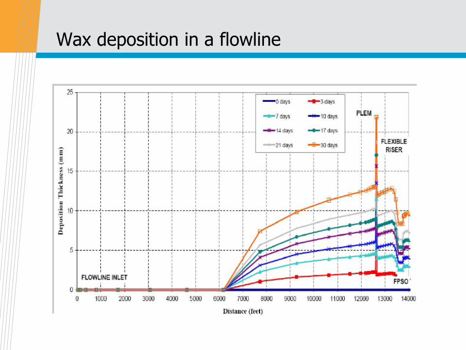
Wax deposition in a flowline

Wax Management
• Thermal insulation and pipeline heating
: Good thermal insulation can keep the fluid above the cloud point for
the whole flowline and thus eliminate wax deposition. However this
can be a problem once the fluids cool down during shut-in.
• Inhibitor injection
: Suppresses cloud point, modify wax crystal structure, coat wax
crystals, or co-crystalize with wax
: The chemicals must match the chemistry of the oil, at the operating
conditions, to be effective.

Wax inhibitors
• Wax Inhibitors
- Thermodynamic wax inhibitor
- Crystal Modifiers: weaken adhesion
- Dispersants/Surfactants: prevent growth
- Pour Point Depressants: reduce viscosity
• Chemistry
- High molecular weight polymers/co-polymers
(such as ethylene vinyl acetate)
- Esters (olefin/maleic;C18-30+)
- Surfactants

Modification of Wax Crystals in STO by a WaxInhibitor

Effectiveness of Chemical Inhibitors
• Can reduce deposition rates but rarely eliminate deposition
- There is no universal wax inhibitor
- Pigging capabilities needed as secondary or backup
• Test chemical inhibitors at expected operating temperatures
conditions with representative oil
- Must match the composition of the specific live oil at applicable
operating conditions
• Optimum wax inhibitor concentration
- Higher concentration can reduce effectiveness
- Injection rates: less than 50 to over 1500 ppm, depend on additive
and system operating conditions
• Inhibitor should be injected above the cloud point to be effective

Wax Inhibitor Effectiveness - Crude Oil

Wax Inhibitor Effectiveness - Condensate

Remediation of a Wax Plug
• Mechanical means
: Pigging (expect 1~3 days down time)
: Pressure surging
: Coiled tubing
• Heating (at least +12 oC WAT)
: Hot oil, hot water, or steam circulation
: Electric heating
• Solvent Flushing
: Often the most successful remediation methods, but also the most
expensive.
: When solvents contact the wax, the deposits are dissolved until the
solvents are saturated.

Wax Control Design Philosophies
• Design the subsea system to operate above the WAT by
thermal insulation.
• Operate the well at sufficiently high production rates to avoid
deposition in the wellbore and tree.
• Remove wax from flowlines by pigging, and pig frequently
enough to ensure that the pig does not stick.
• Utilize insulation and chemicals to reduce pigging frequency.
• Identify and treat high pour point oils continuously.

• In steady-state operation, heat retention (pipeline insulation) is
used to maintain temperatures above WAT along the pipeline,
especially in the deepwater section. Regular operational
pigging will be needed throughout life to remove wax
deposition.
• In transient operations, gelling is the issue. For planned
shutdown and start-ups, inject inhibitors; for unplanned
shutdown, focus on restarting the system within the cooldown
time of pipeline insulation; if this is not possible, use export
pumps to move the gelled plug as early as possible. The
required cool-down time has yet to define by operations.

Asphaltene

Asphaltenes
• Asphaltenes are the most heavy polar/aromatic compounds.
They are not really soluble in most oils but exist as colloidal
suspensions in the oil phase under reservoir condition.
• Asphaltenes carry the bulk of the inorganic component of crude
oil, including sulfur and nitrogen, and metals such as nickel and
vanadium.
• All oils contain a certain amount of asphaltene. Asphaltenes
only become a problem during production when they are
unstable.
Asphaltenes Properties
• The ASTM 0-3279-90 (IP143/90) defines asphaltenes as solids
that precipitate when an excess of n-heptane or n-pentane is
added to a crude oil.
• Asphaltenes do not have a single, unique structure or molecular
weight. Unlike waxes, asphaltenes do not melt. Consequently,
thermal methods do not work to prevent or remediate
asphaltene deposition.

• H/C = 0.8 - 1.4
• Molecular weight:
depends on solvent and concentration
monomer = 500 - 1000
micelles = 1000 - 5000
• Heteroatoms: acting as polar functional group
C=80-85wt% (50-60 wt% aromatics), H=7-10 wt%, S=0.5-10 wt%;
N=0.6-2.6 wt%; O=0.3-4.8 wt%
• Metal elements: Ni, V, Fe

Differences between wax and asphaltene
Asphaltene Wax
Dissolved in heptane No Yes
Crystalline No Yes
Melting point No Yes
Asphaltene Precipitation/Deposition
• Asphaltenes can deposit in reservoirs, wellbore tubing,
flowlines, separators, etc. The deposits can interrupt and
potentially stop production due to the formation of plugs.
• Asphaltenes are suspended by resins as micelles in the crude
oil. Resins are chemically similar to asphaltenes on one end
and similar to alkanes on the other.
• Asphaltenes become unstable as the pressure of the well
decreases and the volume fraction of aliphatic components
increases. If the aliphatic fraction of the oil reaches a threshold
limit, then asphaltenes begin to flocculate and precipitate. This
pressure is called the flocculation point.
• At the bubble point, gas breakout occurs, where lighter gases
such as methane, ethane, and propane are lost from the oil.
These are the very species which remove the stabilizing resins
from asphaltene, destabilizing them and leading to precipitation.

Downhole deposition
• However, the loss of these alkanes increases the solvency of
the crude for asphaltenes, and no further precipitation would be
expected once pressure fall below the bubble point

Assessment of Asphaltene Problem
• One method of characterizing oil is with a SARA (saturates,
aromatics, resins, and asphaltenes) analysis.
• This method breaks the oil down into four pseudo-components
or solubility classes and reports each as a percentage of the
total. The asphaltene fraction is the most polar fraction and is
defined as aromatic soluble and n-alkane insoluble.
• Depressurization of a live bottomhole sample provides the most
direct measurement of asphaltene stability for production
systems.
• During depressurization, the live oil flocculation point or the
pressure at which asphaltenes begin to precipitate in the
system is determined by monitoring the transmittance of an
infrared laser that passes through the sample.

Asphaltene flocculates under microscope
Treating Asphaltene Problems
• Chemical treatment
: Dissolving precipitated asphaltenes with hot aromatic solvents such
as xylene
: Injecting asphaltene inhibitors such as polymeric asphaltene
dispersant chemical
• Plastic coating
: Epoxy resin coatings may stop asphaltenes from sticking and
building up into a deposit
• Engineering solutions
: Dual completions to allow the injection of Xylene directly into the
production stream. Coiled tubing can be used to inject asphaltene
solvents.
• Operational changes
: The greatest risk occurs at pressures just above the bubble point.
The reservoir pressure can be reduced by rapid depletion such the
bubble point occurs away from the production tubing.

Asphaltene Inhibition/Remediation
• Addition of chemicals that are similar to the asphaltene
stabilizing resins and aromatics in crude oil.

Asphaltene control design philosophies
• Inject an asphaltene dispersant continuously into the wellbore
(injection must be at the packer to be effective).
• Install equipment to facilitate periodic injection of an aromatic
solvent into the wellbore for a solvent soak.
• Be financially and logistically prepared to intervene with coiled
tubing in the wellbore to remove deposits.
• Control deposition in the flowline with periodic pigging with
solvents.

Scale

Scale
• Scale is a deposit from precipitated mineral components in
formation water. This is in contrast with waxes and asphaltenes,
which deposit from crude oil.
• Solids may precipitate and deposit from the brine once the
solubility limit is exceeded, which is caused by one of following
ways.
: (Solubility) Due to the change of temperature or pressure for brine
during production, the solubility of some of the inorganic constituents
will decrease and result in the salts precipitating.
: (pH) As pressure decreases, CO2 and H2S (acid gases) vaporize
from the water phase, which increases the pH. Minerals are
generally less soluble at higher pH.
: (Incompatible fluids) When two incompatible waters (such as
formation water rich in calcium and seawater rich in sulfate) are
mixed. Scales formed under these conditions are generally sulfate
scales.

Common Scaling Minerals in Reservoirs
• Calcium Carbonate (calcite)
• Calcium Sulfate (gypsum)
• Barium Sulfate (barite)
• Strontium Sulfate (celesite)

Scale: Saturation Index (SI)
• The solution is said to be saturated when the concentration of
the solute is high enough such that it will no longer remain in
solution at a specified temperature and pressure.
• The saturation index is defined as: SI = log([Me][An]/Ksp)
SI<0: Non-Scaling, SI=0: Equilibrium, SI>0: Scaling Tendency
Where:
[Me] = molality of: Ca2+,Mg2+,Ba2+, Sr2+ or Fe2+
[An] = molality of CO32-, SO4
2-, or S2-
Ksp= solubility product = product of moralities at saturation

Common type of scale
• Calcium Carbonate
- Scaling conditions usually occur from loss of CO2 upon production.
- Scaling can also occur from incompatible waters mixing.
- Higher solubility at lower temperatures.
- Precipitation is slow to start after scaling conditions reached
• Calcium Sulfate
- Scaling usually occurs due to pressure reduction; but also mixing
waters.

• Barium Sulfate (usually with a small amount of Strontium
Sulfate)
- Scaling conditions can occur due to temperature drop during
production.
- Scaling can also occur due to mixing of incompatible waters(water
floods).
- Amounts of scale are relatively small, compared to calcium
carbonate, but precipitation occurs rapidly once scaling conditions
are encountered.
- "Impossible" to dissolve once formed
• Iron Carbonate
- Usually are produced by production process rather than as an
inherent part of reservoir chemistry (except reservoir souring results
in FeS scale)
- Iron scales, especially iron carbonate, inhibit corrosion

Scale Mitigation and Remediation
• Mitigation: As is true in most cases, prevention is much easier
than the cure. Scale deposition is inhibited by chemical injection
downhole
• Remediation: Acid treatments with sequestering agents are
used to dissolve scale and keep it solubilized while it is flushed
out of the flow system. The downside to acid treatments is the
corrosion that is caused on metal surfaces that are contacted.
• Barium Sulfate scale is almost impossible to dissolve.

Scale Inhibitors
• Barite inhibitors are usually amino methylene phosphonates
• Carbonate inhibitors may be phosphonates, polyphosphates or
polymeric anions.
• Time Dependent - Threshold Inhibition
- Inhibitors are used as a much lower dosage than required to keep
all scale in solution. Inhibition is designed to delay the onset of
precipitation.

Corrosion

Corrosion
• Loss of metal
: Metal loss caused be corrosive water
: Fe = Fe++ + 2e-
: Variables
- Material
- H2S and CO2 level in fluids
- Water composition
• Control strategy
: Alter chemical environment
- Oxygen scavengers
- Sulfide scavengers
: Alter reactive surface of metal
- pH control to form protective film
- Corrosion inhibitors
- Polymeric liners to flowlines

Pipeline corrosion examples

Sweet corrosion: CO2
• Dry CO2 gas is itself not corrosive at the temperatures
encountered with oil and gas production. It needs to be
dissolved in an aqueous phase through which it can then
promote electrochemical reaction between steel and the
contacting aqueous phase.
• CO2 dissolves in water to give carbonic acid:CO2 + H2O = H2CO3 = H+ + HCO3
−
: H2CO3 provides a source of H+ ions leading to the normal cathodic
hydrogen evolution reaction and to the metal loss.
: The concentration of dissolved CO2 in solution have a critical
bearing on corrosion rate.
• Areas where CO2 corrosion is most common include flowing
wells, gas condensate wells, areas where water condenses,
tanks filled with CO2, saturated produced water, and pipelines,
which are generally corroded at a slower rate because of lower
temperatures and pressures.

Corrosion Predictions
• Temperature;
• CO2 partial pressure;
• Flow (flow regime and velocity);
• pH;
• Concentration of dissolved corrosion product (FeCO3);
• Concentration of acetic acid;
• Water wetting;
• Metal microstructure (welds);
• Metal prehistory.
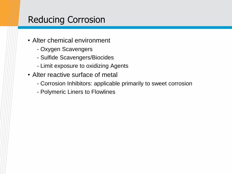
Reducing Corrosion
• Alter chemical environment
- Oxygen Scavengers
- Sulfide Scavengers/Biocides
- Limit exposure to oxidizing Agents
• Alter reactive surface of metal
- Corrosion Inhibitors: applicable primarily to sweet corrosion
- Polymeric Liners to Flowlines
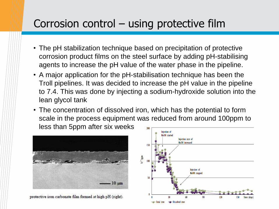
Corrosion control – using protective film
• The pH stabilization technique based on precipitation of protective
corrosion product films on the steel surface by adding pH-stabilising
agents to increase the pH value of the water phase in the pipeline.
• A major application for the pH-stabilisation technique has been the
Troll pipelines. It was decided to increase the pH value in the pipeline
to 7.4. This was done by injecting a sodium-hydroxide solution into the
lean glycol tank
• The concentration of dissolved iron, which has the potential to form
scale in the process equipment was reduced from around 100ppm to
less than 5ppm after six weeks

Corrosion Monitoring
• Corrosion Coupons (must be in the flow stream)
• Produced water analysis for iron
• Smart Pigging
• Common design
: Maximum corrosion allowance is 0.1 mm/yr

Wax, Asphaltene, Scale, Corrosion, Erosion …
Species Flow Situation Mitigation methods
Wax Steady state Insulation, Chemicals, Pigging
Shutdown, Start up NA, except if T < gel point
Asphaltenes Steady state Downhole chemicals, Pigging
Shutdown, Start up NA
Scale Steady state Downhole chemicals
Shutdown, Start up NA
Corrosion Steady state Chemicals, Cathodic protection
Shutdown, Start up NA
Erosion Steady state Flow velocity and solids control
Shutdown, Start up NA
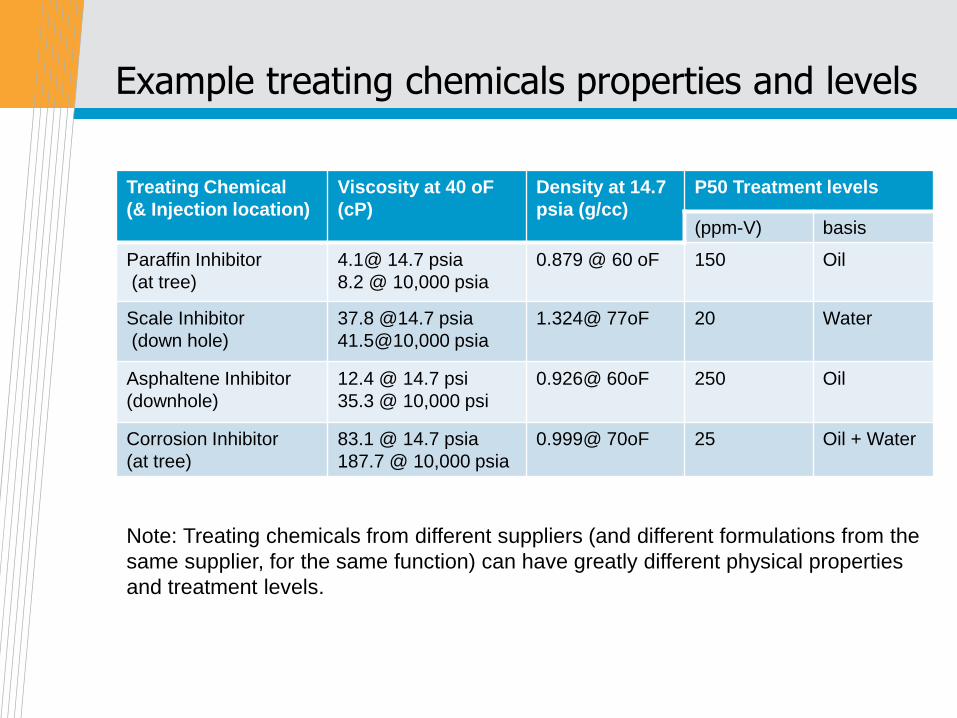
Example treating chemicals properties and levels
Treating Chemical
(& Injection location)
Viscosity at 40 oF
(cP)
Density at 14.7
psia (g/cc)
P50 Treatment levels
(ppm-V) basis
Paraffin Inhibitor
(at tree)
4.1@ 14.7 psia
8.2 @ 10,000 psia
0.879 @ 60 oF 150 Oil
Scale Inhibitor
(down hole)
37.8 @14.7 psia
41.5@10,000 psia
1.324@ 77oF 20 Water
Asphaltene Inhibitor
(downhole)
12.4 @ 14.7 psi
35.3 @ 10,000 psi
0.926@ 60oF 250 Oil
Corrosion Inhibitor
(at tree)
83.1 @ 14.7 psia
187.7 @ 10,000 psia
0.999@ 70oF 25 Oil + Water
Note: Treating chemicals from different suppliers (and different formulations from the
same supplier, for the same function) can have greatly different physical properties
and treatment levels.
