flight times to the heliopause using a combination of ... · also be kept with a combination of...
TRANSCRIPT
Flight Times to the Heliopause Using a Combination
of Solar and Radioisotope Electric Propulsion
IEPC-2011-051
Presented at the 32nd International Electric Propulsion Conference,Wiesbaden, Germany
September 11–15, 2011
Andreas Ohndorf∗
German Aerospace Center (DLR), P.O. 1116, Wessling, 82230, Germany
Bernd Dachwald†
FH University of Applied Sciences, Hohenstaufenallee 6, Aachen, 52064, Germany
Wolfgang Seboldt‡
German Aerospace Center (DLR), Linder Hoehe, Cologne, 51147, Germany
and
Horst W. Loeb and Karl-Heinz Schartner§
University of Giessen, Heinrich Buff Ring 16, Giessen, 35392, Germany
We investigate the interplanetary flight of a low-thrust space probe to the heliopause,located at a distance of about 200 AU from the Sun. Our goal was to reach this distancewithin the 25 years postulated by ESA for such a mission (which is less ambitious than the15-year goal set by NASA). Contrary to solar sail concepts and combinations of ballistic andelectrically propelled flight legs, we have investigated whether the set flight time limit couldalso be kept with a combination of solar-electric propulsion and a second, RTG-poweredupper stage. The used ion engine type was the RIT-22 for the first stage and the RIT-10 forthe second stage. Trajectory optimization was carried out with the low-thrust optimizationprogram InTrance, which implements the method of Evolutionary Neurocontrol, usingArtificial Neural Networks for spacecraft steering and Evolutionary Algorithms to optimizethe Neural Networks’ parameter set. Based on a parameter space study, in which thenumber of thrust units, the unit’s specific impulse, and the relative size of the solar powergenerator were varied, we have chosen one configuration as reference. The transfer timeof this reference configuration was 29.6 years and the fastest one, which is technicallymore challenging, still required 28.3 years. As all flight times of this parameter studywere longer than 25 years, we further shortened the transfer time by applying a launcher-provided hyperbolic excess energy up to 49 km2/s2. The resulting minimal flight time forthe reference configuration was then 27.8 years. The following, more precise optimizationto a launch with the European Ariane 5 ECA rocket reduced the transfer time to 27.5 years.This is the fastest mission design of our study that is flexible enough to allow a launch everyyear. The inclusion of a fly-by at Jupiter finally resulted in a flight time of 23.8 years,which is below the set transfer-time limit. However, compared to the 27.5-year transfer,this mission design has a significantly reduced launch window and mission flexibility if theescape direction is restricted to the heliosphere’s “nose”.
∗Project Manager, Space Operations and Astronaut Training, [email protected]†Professor, Aerospace Engineering, [email protected]‡Senior Scientist, Institute of Space Systems, [email protected].§Professor, 1st Institute of Physics, {horst.w.loeb|karl-heinz.schartner}@exp1.physik.uni-giessen.de
1The 32nd International Electric Propulsion Conference, Wiesbaden, Germany
September 11–15, 2011
Nomenclature
AU = astronomical unit, mean Earth-Sun distance (1 AU = 149 597 870 697 m)C3 = hyperbolic excess energyd = Gravity Assist (GA) fly-by distanceJ = cost function, fitnessm0 = launch massmp = propellant massn = number of ion thrustersPc = solar power generator electrical power output at 1 AU distance from the Sun;
fraction of PmPm = maximum electrical power of the SEP stagev∞ = hyperbolic excess velocityIsp = specific impulser = distanceRJ = Jupiter radiusU+ = acceleration grid voltaget = (modified Julian) date (MJD)∆t = transfer duration∆v = velocity incrementwij = connection weight between neuron i and neuron jyi = output value of neuron iγ = fit parameterγi = temperature parameter of neuron iπ = network parameter vectorθi = threshold value of neuron i
I. Introduction
The outer regions of the heliosphere, where the solar wind encounters the local interstellar medium at adistance of approximately 200 astronomical units (AU), are of scientific interest for decades1. We do not knowif our models of the processes in that intermediate region are correct and therefore need to test the underlyingtheories with direct measurements. The problem that inhibits us from making these measurements is thevast distance of 200 AU. No spacecraft has yet traveled that far, and, according to current mission planning∗,even the deep space probes Voyager 1 and 2 are uncertain to be still able to return scientific data when theyhave reached 130 – 140 AU, which will be 2015 for Voyager 1.ESA and NASA have therefore both included such an Interstellar Heliopause Probe (IHP) mission into theirstrategic programs. The maximum allowed mission duration is 25 years for ESA missions and 15 yearsfor NASA missions, which corresponds to average velocities of 8 AU/yr and 13.3 AU/yr, respectively. Suchaverage flight velocities and the resulting total velocity increments (∆v) pose a challenging requirement tocurrent propulsion systems. In fact, the unavailability of mature propulsion systems having the requiredperformance characteristics is the main reason why such a mission has not yet been undertaken.A promising propulsion concept that enables a large ∆v is solar sailing. It has been used for past IHP missionstudies2,3, and also radioisotope power generation with electric propulsion in combination with hyperbolicexcess energy and gravity assist maneuvers were investigated4. Solar sailing, however, is still far frompractical big-scale realization. Therefore we investigated a different, technically more mature, propulsionconcept and supported our concept with trajectory optimization runs carried out with the program InTrance.This program can optimize low-thrust trajectories by making use of Artificial Neural Networks (ANN) andEvolutionary Algorithms (EA) in a method called Evolutionary Neurocontrol (ENC). Our concept consists ofthe IHP science probe, which is propelled by a solar-electric propulsion (SEP) stage with RIT-22-type thrust
∗http://voyager.jpl.nasa.gov/spacecraft/spacecraftlife.html
2The 32nd International Electric Propulsion Conference, Wiesbaden, Germany
September 11–15, 2011
modules. Additionally, a second upper stage accelerates – after jettison of the SEP-stage – the probe withsmaller RIT-10-engines that are powered by four radioisotope thermal generators (RTG). We started witha variation of the solar power generator characteristic power Pc, the number of thrust modules n, and thethrust modules acceleration grid voltage U+ and therefore its specific impulse, Isp, to determine the transfertime’s sensitivity to these parameters. These optimization runs were conducted with hyperbolic excess energy(relative to Earth) C3 = 0 for 27 SEP-only and for 27 SEP+REP configurations. The resulting transfertimes were still above the 25-year limit and then we included the potential launcher-provided hyperbolicexcess energy for interplanetary injection, e.g., by an Ariane 5 ECA, which reduced the flight time further,but still being above 25 years. Finally, we included a gravity assist at Jupiter which resulted in a transfertime of only 23.4 years.
II. Low-Thrust Trajectory Optimization with InTrance
For the trajectory calculations within this work we used the low-thrust trajectory optimization softwareInTrance, which stands for “Intelligent Trajectory optimization using neurocontroller evolution”, developedby two of us (B. Dachwald and A. Ohndorf). It is an implementation of the Evolutionary Neurocontrol(ENC) method - a combination of Artificial Neural Networks (ANN) and Evolutionary Algorithms (EA).The ANN is used to steer a low-thrust spacecraft (nearly) globally optimal, whereas the EA is used to trainthe ANN for this specific optimal control task. Both concepts are only briefly described in the next threesubsections, but more detailed descriptions can be found in Refs. 5-7. The final subsection briefly deals withthe spacecraft configurations that we used for the presented trajectory results. However, as the design andits design-driving requirements are treated extensively in Ref. 8, only the parameters that are relevant forthe trajectory calculations are introduced.
A. Artificial Neural Networks
ANNs are the result of the attempt to make use of advantageous features of the biological brain, e.g.information storage and processing, fault tolerance, generalization, and decision making. Like their biologicalprototype, ANNs basically comprise simple processing units, the neurons, and multiple connections betweenthem, i.e. one neuron receives information from at least one other neuron, and provides its own output toother neurons. The output is determined by the sum of all input information and the transfer function oractivation function, which is inherent to each neuron. The respective transfer function can be simple, e.g.a step or a linear function, but throughout this study we have used the commonly used sigmoid transferfunction. For every neuron i, the output yi is calculated from the output yj of all input neurons j via
yi =1
1 + e−(∑j wijyj−θi)/γi
, (1)
with the connection weights wij between neuron i and all input neurons j, the threshold value or bias θi ofneuron i, and the temperature parameter γi of neuron i. An advantage of the sigmoid is its ability to mimicthe step function and linear functions, by adjusting the temperature parameter, while still being steady andlimiting the output to a minimal and maximal value.A single neuron’s capabilities are limited to its transfer function, but through the interconnection of morethan one neuron complex transfer functions become achievable. The only approximately 100 000 cells of afly brain, for example, enable the fly not only to sense its environment, to find food, and to reproduce, butalso to manage the challenging flight control system. The key to success is the optimized transfer behaviorof the fly’s neurons and their interconnectivity. Using sigmoid-type neurons, the ANN’s degree of optimalityis then determined by the parameters wij , θi, and γi of all neurons i. If organized in a parameter vectorπ = (π1, . . . , πk, . . . , πm), where the πk are the ANN parameters (wij , θi, and γi), this m-dimensional vectorcompletely defines the so-called network function Nπ.For this study we have used ANNs whose internal neurons are organized in layers: the input layer receiving theproblem-dependent information (the environment), the output layer giving the network function’s result (thecontrol), and eventually existing so-called hidden layers between them. Feed-forward connections transportinformation between two consecutive layers and thus make data propagation though the ANN deterministic.This type of ANN is called layered feed-forward ANN and has been successfully applied to a number ofclassification and control problems.
3The 32nd International Electric Propulsion Conference, Wiesbaden, Germany
September 11–15, 2011
B. Evolutionary Algorithms
Natural evolution provides the enabling principles of evolutionary computer paradigms, one of which beingthe Evolutionary Algorithm or Genetic Algorithm. This type of global optimization method has been suc-cessfully used to solve a number of very different problems and in the following the essential elements ofEAs are briefly described whereas the explanation is constrained on how these elements are implemented inInTrance. Many of the explained general elements do also exist in different implementations but were notused for this study. These elements are again derived from natural evolution and are therefore the populationand the mechanisms of selection, crossover, mutation, and evaluation.A core element of EAs is the population, which is a collection of potential solutions to the problem. Usingbiologic terms, these solution candidates are also called individuals, or chromosomes, or strings ξ. Each indi-vidual incorporates exactly one potential solution of the given problem. At the beginning of the algorithm,however, when all individuals are initialized with more or less random content, every solution is far fromsolving the problem at all or being optimal. If a population member solves the problem at all and, if that isthe case, how good it solves the problem, is measured with a single scalar value. It is called objective value,cost function, fitness value, or only the fitness J . With this performance metric all population members arenow comparable w.r.t. suitability to solve the problem. The higher the fitness the better an individual solvesthe given problem.The second EA element is selection. InTrance uses tournament selection and randomly selects four individu-als and pairwise compares their fitness values to determine two “winner” and two “looser” individuals. Thewinners are allowed to reproduce and create offspring individuals. The inferior solutions are replaced by thenew offspring solutions and therefore become extincted.Crossover, the third algorithm element, takes place after selection. The “winner” individuals’ genome infor-mation is used to form two new individuals. These newborn solution candidates therefore contain genomeinformation of both parents. A simple method is uniform crossover, during which genome information isalternately taken from “winner” solution one and “winner” individual two.The next algorithm element, the mutation, is applied after crossover and introduces a small random changeto the value at an also randomly chosen position of the genome code. It helps to to explore the solutionspace more thoroughly and less dependently on only the population’s total genome code.The final element is the evaluation. It is the problem-dependent element of an EA and assigns the necessaryfitness to the newborn population members after mutation. Evaluation is the last algorithm step and a newcycle can start with selection.The enabling principle of EA is the concept of survival of the fittest. The individual that is adapted best toits current environment has the highest chance to reproduce and therefore to contribute its genome code tothe population genome information. With continuing algorithm runtime, the population members’ genomesmore and more resemble each other and the divergence among their fitness values decreases. At the sametime, the population’s maximum fitness will increase until no more improvement is achievable. Dependingon set convergence criteria, InTrance then either stops or initializes a new population based on the formerbest solution.
C. Evolutionary Neurocontrol for spacecraft steering
The preceding two subsections describe a method that is applicable to optimal control problems, but forwhich the optimal parameter vector has to be determined. In Ref. 5, an ANN and an EA have beensuccessfully combined to ENC and the applicability of this method as a robust solver for interplanetarylow-thrust trajectory optimization problems that needs no initial guess has been demonstrated. Afterwards,ENC was extended by the lead author to planetary low-thrust transfer problems, low-thrust transfers thatcomprise a change of the central body9, and flight-phase dependent (staged) propulsion systems. The latterenabled the trajectory analysis for the presented study.For low-thrust trajectory optimization, ENC works in two nested loops. The inner loop, the trajectoryintegration loop, uses an ANN to determine the optimal thrust vector direction and magnitude before eachintegration step. The ANN is called Neurocontroller (NC) in this context. Spacecraft state and targetstate information (position, velocity, fuel) is provided to the NC before every integration step and the NCprovides the actual control variables through its output neurons. The next integration step is carried outwith the spacecraft state vector and the control variables. As an NC’s network function Nπ is determinedby the network parameter vector π, one needs to find the optimal parameter vector π∗ to fly a low-thrust
4The 32nd International Electric Propulsion Conference, Wiesbaden, Germany
September 11–15, 2011

spacecraft optimally along its trajectory. The NC-parameters are provided by the EA in the outer loop.The genome information of every population member ξ corresponds to a parameter vector π and thereforeexactly determines one, potentially optimal, solution strategy of the transfer problem. The outer EA-loop,on the other hand, needs an evaluation element to function, and this is implemented through the evaluationof the resulting trajectory at the end of the inner loop. Each solution is assessed w.r.t. to the violationof problem-specific boundary constraints, e.g. final distance to the target in case of fly-by problems and,additionally, the relative velocity in case of rendezvous-type transfers. These constraints are usually user-provided maximum limits. If no limit was violated, the solution is assessed w.r.t. the actual optimizationcriterion. For low-thrust trajectory optimization problems this is usually either the transfer duration, or theconsumed propellant mass, or a combination of both.
D. Spacecraft setup and parameter variation
To carry out trajectory integrations during the optimization runs with InTrance, we had to determine thespacecraft configurations for the different propulsion options. This was necessary to obtain values of theproblem-determining variables, e.g., the total mass m0, the propellant mass mp, and the available max-imum thrust in order to configure InTrance accordingly. The scientific IHP payload was estimated withmpl = 245 kg for the SEP-only case and with mpl = 498 kg for the SEP+REP-option (including the REP-stage)8,10. The SEP-stage was used by all designs; its main components are the structure, the solar powergenerator with the solar panels, the Xe-filled propellant tank, and the RIT-22 thrust modules.The solar power generator mass was dependent on its characteristic power Pc, which was defined as theelectrical power output at the characteristic distance r = 1 AU. We chose the unit of percent to express atwhich power level the SEP-stage could operate at launch, i.e. Pc = 65 % allowed the SEP-stage to operatewith sixty five percent of maximum available thrust. This proved benficial because it allowed saving of powersystem and resulting mass. Furthermore, the optimizer was free to explore trajectories with thrust arcs insideEarth orbit, where the spacecraft’s full thrust potential could be exploited. Although the trajectory pathlength thus usually increases, compared to direct transfers, the transfer time can be reduced as accelerationdeep in the Sun’s gravitiy well is more efficient. We assumed a power-specific mass of 5 kg/kW, which is arealistic assumption when looking at recent developments for deep space mission power generation11.InTrance allows the configuration of a user-provided fixed value for the tank mass, or a propellant-mass-dependent one. The latter option requires the provision of the tank mass fraction w.r.t. the propellant mass.A realistic value of this parameter is 0.06.The thrust modules were of RIT-22-type, an ion engine having been qualified by EADS Astrium SpaceTransportation. Each of the engines of the propulsion stage was operated at throttle levels between 65 and100% whereas the NC commanded the actual setting.The following performance-determining parameters of the propulsion stage were varied to find the configu-ration that yields the shortest mission duration:
• the number of thrust units, n
• the beam voltage of a RIT-22 thrust unit, U+, and the resulting specific impulse, Isp
• the electrical power of the solar power generator at 1 AU solar distance, Pc
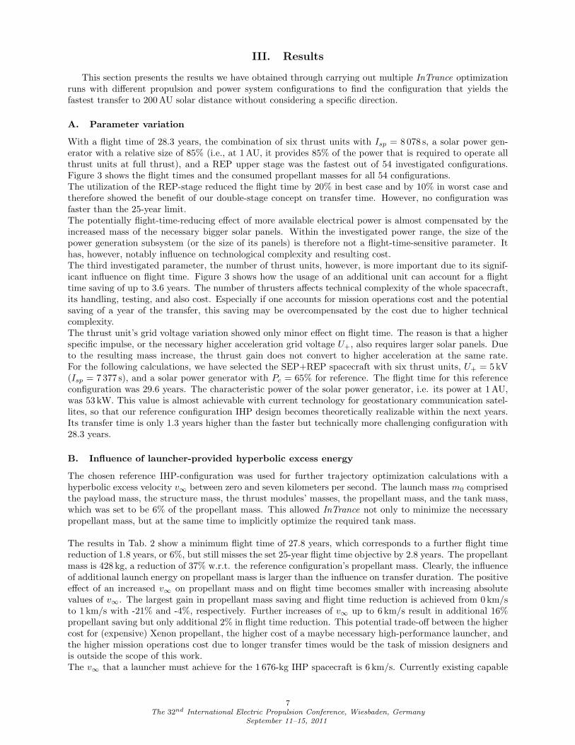
The SEP-stage contained 4–6 thrust units with beam voltages of 5, 6, or 7 kV. These correspond to an Ispof 7 377, 8 078, and 8 723 s, respectively (see also Table 1). We chose a characteristic electrical power Pc of65%, 75%, and 85%. The allowed minimal distance to Sun was set to 0.7 AU to prevent thermal problemsthat might require a special thermal protection system. The REP-stage increased the payload mass for theSEP-stage to 498 kg, and it used a RIT-10-type thruster type with P = 592 W, (four RTG-based batterieswith powerspecific mass of 8.5 W/kg and Begin-Of-Mission (BOM) power of 648 W) Isp = 3 810 s, a nominalthrust F = 21 mN, and a propellant mass flow mp = 0.558 mg/s. With a RIT-10 lifetime of approx.23 000 h, four thrust units were necessary to process 158 kg of Xe. The model shown in Fig. 1 and Fig. 2gives an impression of our IHP spacecraft design with the SEP-stage and the spin-stabilized REP upperstage. We have investigated 54 different spacecraft configurations, being a combination of two differentpropulsion concepts, three different numbers of thrust units, three different Isps, and three different solarpower generator sizes (as compared to the power that is required by all thrusters at full thrust). Thesecalculations were carried out with C3=0 (relative to Earth) to assure comparability.
5The 32nd International Electric Propulsion Conference, Wiesbaden, Germany
September 11–15, 2011
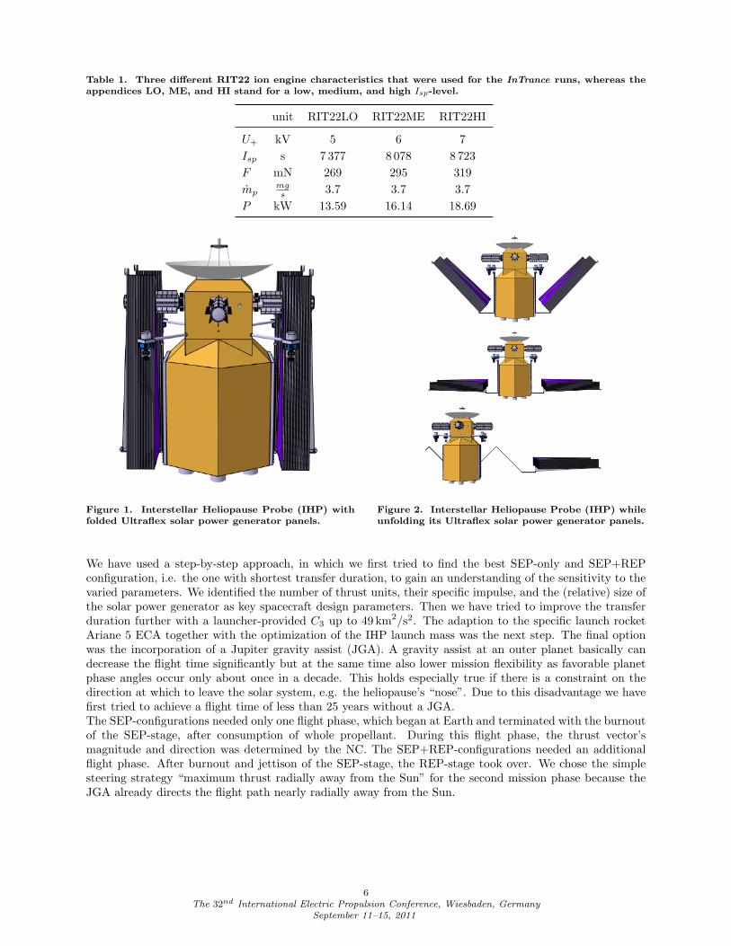
Table 1. Three different RIT22 ion engine characteristics that were used for the InTrance runs, whereas theappendices LO, ME, and HI stand for a low, medium, and high Isp-level.
unit RIT22LO RIT22ME RIT22HI
U+ kV 5 6 7Isp s 7 377 8 078 8 723F mN 269 295 319mp
mgs 3.7 3.7 3.7
P kW 13.59 16.14 18.69
Figure 1. Interstellar Heliopause Probe (IHP) withfolded Ultraflex solar power generator panels.
Figure 2. Interstellar Heliopause Probe (IHP) whileunfolding its Ultraflex solar power generator panels.
We have used a step-by-step approach, in which we first tried to find the best SEP-only and SEP+REPconfiguration, i.e. the one with shortest transfer duration, to gain an understanding of the sensitivity to thevaried parameters. We identified the number of thrust units, their specific impulse, and the (relative) size ofthe solar power generator as key spacecraft design parameters. Then we have tried to improve the transferduration further with a launcher-provided C3 up to 49 km2/s2. The adaption to the specific launch rocketAriane 5 ECA together with the optimization of the IHP launch mass was the next step. The final optionwas the incorporation of a Jupiter gravity assist (JGA). A gravity assist at an outer planet basically candecrease the flight time significantly but at the same time also lower mission flexibility as favorable planetphase angles occur only about once in a decade. This holds especially true if there is a constraint on thedirection at which to leave the solar system, e.g. the heliopause’s “nose”. Due to this disadvantage we havefirst tried to achieve a flight time of less than 25 years without a JGA.The SEP-configurations needed only one flight phase, which began at Earth and terminated with the burnoutof the SEP-stage, after consumption of whole propellant. During this flight phase, the thrust vector’smagnitude and direction was determined by the NC. The SEP+REP-configurations needed an additionalflight phase. After burnout and jettison of the SEP-stage, the REP-stage took over. We chose the simplesteering strategy “maximum thrust radially away from the Sun” for the second mission phase because theJGA already directs the flight path nearly radially away from the Sun.
6The 32nd International Electric Propulsion Conference, Wiesbaden, Germany
September 11–15, 2011
III. Results
This section presents the results we have obtained through carrying out multiple InTrance optimizationruns with different propulsion and power system configurations to find the configuration that yields thefastest transfer to 200 AU solar distance without considering a specific direction.
A. Parameter variation
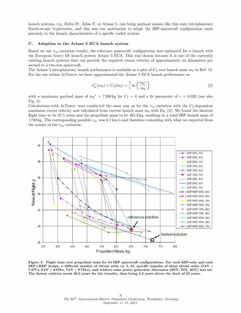
With a flight time of 28.3 years, the combination of six thrust units with Isp = 8 078 s, a solar power gen-erator with a relative size of 85% (i.e., at 1 AU, it provides 85% of the power that is required to operate allthrust units at full thrust), and a REP upper stage was the fastest out of 54 investigated configurations.Figure 3 shows the flight times and the consumed propellant masses for all 54 configurations.The utilization of the REP-stage reduced the flight time by 20% in best case and by 10% in worst case andtherefore showed the benefit of our double-stage concept on transfer time. However, no configuration wasfaster than the 25-year limit.The potentially flight-time-reducing effect of more available electrical power is almost compensated by theincreased mass of the necessary bigger solar panels. Within the investigated power range, the size of thepower generation subsystem (or the size of its panels) is therefore not a flight-time-sensitive parameter. Ithas, however, notably influence on technological complexity and resulting cost.The third investigated parameter, the number of thrust units, however, is more important due to its signif-icant influence on flight time. Figure 3 shows how the usage of an additional unit can account for a flighttime saving of up to 3.6 years. The number of thrusters affects technical complexity of the whole spacecraft,its handling, testing, and also cost. Especially if one accounts for mission operations cost and the potentialsaving of a year of the transfer, this saving may be overcompensated by the cost due to higher technicalcomplexity.The thrust unit’s grid voltage variation showed only minor effect on flight time. The reason is that a higherspecific impulse, or the necessary higher acceleration grid voltage U+, also requires larger solar panels. Dueto the resulting mass increase, the thrust gain does not convert to higher acceleration at the same rate.For the following calculations, we have selected the SEP+REP spacecraft with six thrust units, U+ = 5 kV(Isp = 7 377 s), and a solar power generator with Pc = 65% for reference. The flight time for this referenceconfiguration was 29.6 years. The characteristic power of the solar power generator, i.e. its power at 1 AU,was 53 kW. This value is almost achievable with current technology for geostationary communication satel-lites, so that our reference configuration IHP design becomes theoretically realizable within the next years.Its transfer time is only 1.3 years higher than the faster but technically more challenging configuration with28.3 years.
B. Influence of launcher-provided hyperbolic excess energy
The chosen reference IHP-configuration was used for further trajectory optimization calculations with ahyperbolic excess velocity v∞ between zero and seven kilometers per second. The launch mass m0 comprisedthe payload mass, the structure mass, the thrust modules’ masses, the propellant mass, and the tank mass,which was set to be 6% of the propellant mass. This allowed InTrance not only to minimize the necessarypropellant mass, but at the same time to implicitly optimize the required tank mass.
The results in Tab. 2 show a minimum flight time of 27.8 years, which corresponds to a further flight timereduction of 1.8 years, or 6%, but still misses the set 25-year flight time objective by 2.8 years. The propellantmass is 428 kg, a reduction of 37% w.r.t. the reference configuration’s propellant mass. Clearly, the influenceof additional launch energy on propellant mass is larger than the influence on transfer duration. The positiveeffect of an increased v∞ on propellant mass and on flight time becomes smaller with increasing absolutevalues of v∞. The largest gain in propellant mass saving and flight time reduction is achieved from 0 km/sto 1 km/s with -21% and -4%, respectively. Further increases of v∞ up to 6 km/s result in additional 16%propellant saving but only additional 2% in flight time reduction. This potential trade-off between the highercost for (expensive) Xenon propellant, the higher cost of a maybe necessary high-performance launcher, andthe higher mission operations cost due to longer transfer times would be the task of mission designers andis outside the scope of this work.The v∞ that a launcher must achieve for the 1 676-kg IHP spacecraft is 6 km/s. Currently existing capable
7The 32nd International Electric Propulsion Conference, Wiesbaden, Germany
September 11–15, 2011
launch systems, e.g. Delta IV, Atlas V, or Ariane 5, can bring payload masses like this onto interplanetaryEarth-escape trajectories, and this was our motivation to adapt the IHP-spacecraft configuration moreprecisely to the launch characteristics of a specific rocket system.
C. Adaption to the Ariane 5 ECA launch system
Based on our v∞-variation results, the reference spacecraft configuration was optimized for a launch withthe European heavy lift launch system Ariane 5 ECA. This was chosen because it is one of the currentlyexisting launch systems that can provide the required excess velocity of approximately six kilometers persecond to a two-ton spacecraft.The Ariane 5 interplanetary launch performance is available as a plot of C3 over launch mass m0 in Ref. 12.For the use within InTrance, we have approximated the Ariane 5 ECA launch performance as
v2∞(m0) = C3(m0) =
1γ
ln(m0∗
m0
)(2)
with a maximum payload mass of m0∗ = 7 200 kg for C3 = 0 and a fit parameter of γ = 0.032 (see also
Fig. 4).Calculations with InTrance were conducted the same way as for the v∞-variation with the C3-dependentmaximum excess velocity now calculated from current launch mass m0 with Eq. (2). We found the shortestflight time to be 27.5 years and the propellant mass to be 461.2 kg, resulting in a total IHP launch mass of1 720 kg. The corresponding possible v∞ was 6.7 km/s and therefore coinciding with what we expected fromthe results of the v∞-variation.
Figure 3. Flight time over propellant mass for 54 IHP spacecraft configurations. For each SEP-only and eachSEP+REP design, a different number of thrust units (4, 5, 6), specific impulse of these thrust units (5 kV /7 377 s, 6 kV / 8 078 s, 7 kV / 8 723 s), and relative solar power generator dimension (65%, 75%, 85%) was set.The fastest solution needs 28.3 years for the transfer, thus being 3.3 years above the limit of 25 years.
8The 32nd International Electric Propulsion Conference, Wiesbaden, Germany
September 11–15, 2011

Table 2. Propellant mass (mp), launch mass (m0), and flight time to 200 AU (∆t) for the reference configuration(six RIT-22 with Isp = 7 377 s and 53 kW solar power generator) with a hyperbolic excess velocity v∞ =
√C3
between 0 and 7 km/s.
v∞, km/s mp, kg m0, kg ∆t, yr
0 676 2 095 29.61 537 (-21%) 1 821 28.5 (-4%)2 512 (-24%) 1 787 28.4 (-4%)3 486 (-28%) 1 753 28.2 (-5%)4 449 (-34%) 1 703 28.0 (-5%)5 441 (-35%) 1 693 27.9 (-6%)6 428 (-37%) 1 676 27.8 (-6%)7 422 (-38%) 1 668 28.0 (-5%)
Figure 4. Hyperbolic excess energy C3 that an Ari-ane 5 ECA can give to a spacecraft with launch massm0. The exact figures from Ref. 12 are approximatedwith a fit curve according to Eq. (2).
Figure 5. Best solution without gravity assist; launchwith Ariane 5 ECA
9The 32nd International Electric Propulsion Conference, Wiesbaden, Germany
September 11–15, 2011
D. Gravity assist at Jupiter
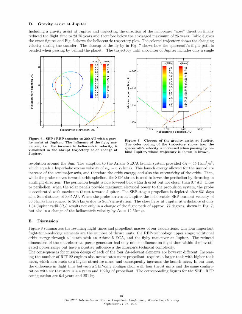
Including a gravity assist at Jupiter and neglecting the direction of the heliopause “nose” direction finallyreduced the flight time to 23.75 years and therefore below the envisaged maximum of 25 years. Table 3 givesthe exact figures and Fig. 6 shows the heliocentric trajectory plot. The colored trajectory shows the changingvelocity during the transfer. The closeup of the fly-by in Fig. 7 shows how the spacecraft’s flight path isbended when passing by behind the planet. The trajectory until encounter of Jupiter includes only a single
Figure 6. SEP+REP transfer to 200 AU with a grav-ity assist at Jupiter. The influence of the flyby ma-neuver, i.e. the increase in heliocentric velocity, isvisualized in the abrupt trajectory color change atJupiter.
Figure 7. Closeup of the gravity assist at Jupiter.The color coding of the trajectory shows how thespacecraft’s velocity is increased when passing by be-hind Jupiter, whose trajectory is shown in brown.
revolution around the Sun. The adaption to the Ariane 5 ECA launch system provided C3 = 45.1 km2/s2,which equals a hyperbolic excess velocity of v∞ = 6.72 km/s. This launch energy allowed for the immediateincrease of the semimajor axis, and therefore the orbit energy, and also the eccentricity of the orbit. Then,while the probe moves towards orbit aphelion, the SEP-thrust is used to lower the perihelion by thrusting inantiflight direction. The perihelion height is now lowered below Earth orbit but not closer than 0.7 AU. Closeto perihelion, when the solar panels provide maximum electrical power to the propulsion system, the probeis accelerated with maximum thrust towards Jupiter. The SEP-stage’s propellant is depleted after 831 daysat a Sun distance of 3.05 AU. When the probe arrives at Jupiter the heliocentric SEP-burnout velocity of30.5 km/s has reduced to 26.8 km/s due to Sun’s gravitation. The close flyby at Jupiter at a distance of only1.34 Jupiter radii (RJ) results not only in a change of the flight path of approx. 77 degrees, shown in Fig. 7,but also in a change of the heliocentric velocity by ∆v = 12.5 km/s.
E. Discussion
Figure 8 summarizes the resulting flight times and propellant masses of our calculations. The four importantflight-time-reducing elements are the number of thrust units, the REP-technology upper stage, additionalorbit energy through a launch with an Ariane 5 ECA, and the flyby maneuver at Jupiter. The reduceddimensions of the solarelectrical power generator had only minor influence on flight time within the investi-gated power range but have a positive influence a the mission’s technical complexity.The consequences for mission design of each of the four ∆t-relevant elements are however different. Increas-ing the number of RIT-22 engines also necessitates more propellant, requires a larger tank with higher tankmass, which also leads to a higher structure mass, and consequently increases the launch mass. In our case,the difference in flight time between a SEP-only configuration with four thrust units and the same configu-ration with six thrusters is 4.4 years and 192 kg of propellant. The corresponding figures for the SEP+REPconfiguration are 6.4 years and 251 kg.
10The 32nd International Electric Propulsion Conference, Wiesbaden, Germany
September 11–15, 2011
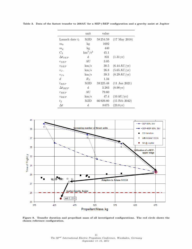
Table 3. Data of the fastest transfer to 200AU for a SEP+REP configuration and a gravity assist at Jupiter
unit value
Launch date tl MJD 58 254.59 (17 May 2018)m0 kg 1692mp kg 440C3 km2/s2 45.1∆tSEP d 831 (1.31 yr)rSEP AU 3.05vSEP km/s 30.5 (6.44 AU/yr)vJ− km/s 26.8 (5.65 AU/yr)vJ+ km/s 39.3 (8.29 AU/yr)d RJ 1.34tREP MJD 59 225.48 (11 Jan 2021)∆tREP d 3.283 (8.98 yr)rREP AU 79.60vREP km/s 47.4 (10 AU/yr)tf MJD 66 929.80 (15 Feb 2042)∆t d 8 675 (23.8 yr)
Figure 8. Transfer duration and propellant mass of all investigated configurations. The red circle shows thechosen reference configuration.
11The 32nd International Electric Propulsion Conference, Wiesbaden, Germany
September 11–15, 2011
IV. Conclusions
Following the flight time limit of 25 years set by ESA for a mission to the heliopause at 200 AU, we haveshown that a combination of SEP+REP is a competitive option to solar sailing, which is not yet matureenough for such a mission, and to a combination of electrical and chemical propulsion. However, this was onlypossible by including a Jupiter gravity assist (JGA). As this particular mission element severely constrainsthe launch window to a single launch opportunity about every decade, the mission flexibility is significantlyreduced. Any mission preparation delay can put the entire mission at risk. That risk is avoidable througha raise of the flight time limit by only 2.5 years. We have shown that with a staged SEP+REP propulsionsystem and a capable launcher like the Ariane 5 ECA, a flight time of 27.5 years to 200 AU is achievable. Thisis only 10% longer than the ESA limit and 16% longer than our fastest JGA-solution with 23.8 years. Atthe same time, this mission concept is more flexible, as it does not need any gravity assist and can thereforelaunch every year.
Acknowledgments
The support of this work by the German Aerospace Center DLR (project number DLR 50 RS 0901) isgratefully acknowledged.
References
1Jaffe, L. J., Ivie, C. V., “Science Aspects of a Mission Beycond the Planets,” Icarus, Vol. 39, No. 3,1979, pp. 486-494.
2Liewer, P. C., Mewaldt, R. A., Ayon, J. A., Garner, C., Gavit, S., Wallace, R. A., “Interstellar Probeusing a Solar Sail: Conceptual Design and Technological Challenges,” The Outer Heliosphere: The NextFrontiers, edited by K. Scherer, H. Fichtner, H.J. Fahr and E. Marsch, COSPAR Colloquiua Series, 11,Pergamon Press, Amsterdam, 2001, p 411
3Lyngvi, A. E., van den Berg, M. L., and Falkner, P., “Study Overview of the Interstellar HelopauseProbe,” SCI-A/2006/114/IHP, Nordwijk, The Netherlands, 2007
4McNutt jr., R. L., Wimmer-Schweingruber, R. F., “Enabling Interstellar Probe,” Acta Astronautica,Vol. 68, No. 7-8, 2011, pp. 790-801
5Dachwald, B., “Low-Thrust Trajectory Optimization and Interplanetary Mission Analysis Using Evo-lutionary Neurocontrol” Ph.D. Dissertation, Aerospace Dept., University of the Armed Forces Germany,Munich, Germany, 2004.
6Dachwald, B., “Optimization of Interplanetary Solar Sailcraft Trajectories Using Evolutionary Neuro-control,” AIAA Journal of Guidance, Control, and Dynamics, Vol. 27, No. 1, 2004, pp. 66-72.
7Dachwald, B., “Evolutionary Neurocontrol: A Smart Method for Global Optimization of Low-ThrustTrajectories,” AIAA Astrodynamics Specialist Conference, AIAA-2003-4573, Vol. 1, AIAA, Providence,Rhode Island, 2004, pp. 103-115
8Loeb, H. W., Schartner, K.H., Dachwald, B., Ohndorf, A., Seboldt W., “Solar/Radioisotope ElectricPropulsion Combination for a Mission to the Heliopause,” 32nd International Electric Propulsion Conference,IEPC-2011-052, Wiesbaden, Germany, Sep. 11-15, 2011
9Ohndorf, A., Dachwald, B., Gill, E., “Optimization of Low-Thrust Earth-Moon Transfers Using Evolu-tionary Neurocontrol,”IEEE Conference on Evolutionary Computation, CEC-2009-368, Trondheim, Norway,May 18-21, 2009
10Loeb, H. W., Schartner, K.H., Dachwald, B., Ohndorf, A., Seboldt W., “Heliopause Probe-SEP Op-tion,” German Aerospace Center DLR, DLR 50 RS 0901, Bonn, Germany, 2010
11Spence, B., White, S., Wilder, N., Gregory, T., Douglas, M., Takeda, R., Mardesich, N., Peterson,T., Hillard, B., Sharps, P., Fatemi, N., “Next generation ultraflex solar array for NASA’s New MillenniumProgram Space Technology 8,” IEEE Aerospace Conference, Big Sky, Montana, 2005, pp. 824-836
12Ancarola, P., B, “Ariane 5 Performance Optimisation For Interplanetary Missions,” AIAA Astrody-namics Specialist Conference and Exhibit, AIAA-2002-4902, Monterey, California, Aug. 5-8, 2002
12The 32nd International Electric Propulsion Conference, Wiesbaden, Germany
September 11–15, 2011