heliopause electrostatic rapid transit system (herts) · heliopause electrostatic rapid transit...
TRANSCRIPT

American Institute of Aeronautics and Astronautics
1
Heliopause Electrostatic Rapid Transit System (HERTS)
Bruce M. Wiegmann1
NASA, George C. Marshall Space Flight Center, AL, 35812, United States
A recent six month investigation focused on: “Determining the benefits of propelling a scientific spacecraft by an ‘Electric Sail’ propulsion system to the edge of our solar system (the Heliopause), a distance of 100 to 120 AU, in ten years or less” has recently been completed by the Advance Concepts Office at NASA’s MSFC. The concept investigated has been named the Heliopause Electrostatic Rapid Transit System (HERTS) by the MSFC team. The HERTS is a revolutionary propellant-less propulsion concept that is ideal for deep space missions to the Outer Planets, Heliopause, and beyond. It is unique in that it uses momentum exchange from naturally occurring solar wind protons to propel a spacecraft within the heliosphere. The propulsion system consists of an array of electrically positively-biased wires that extend outward 20 km from a rotating (one revolution per hour) spacecraft. It was determined that the HERTS system can accelerate a spacecraft to velocities as much as two to three times that possible by any realistic extrapolation of current state-of-the-art propulsion technologies—including solar electric and solar sail propulsion systems. The data produced show that a scientific spacecraft could reach distances of 100AU in <10 years. Moreover, it can be reasonably expected that this system could be developed within a decade and provide meaningful Heliophysics Science and Outer Planetary Science returns in the 2025-2035 timeframe
Nomenclature F = Total force mp = proton mass np = number density of solar protons v = velocity of solar protons Nw = Number of wires in propulsion system Lw = Length of single wire P+ = proton impact parameter, Te = electron temperature in oK ne = the number of electrons per cm3 = magnitude of the applied positive potential, D = the Debye shielding distance
I. Introduction he Electric Solar Wind Sail (E-Sail) is a revolutionary propulsion technology that uses the naturally occurring solar winds to produce thrust without the expense (mass) of propellants that enables trip times to the edge of the
solar in half of the time as any alternative system. In addition to these benefits (reductions in travel times to solar system targets and launch costs) this system will enable qualitatively new types of non-Keplerian orbit missions. The E-sail taps the momentum flux of the natural solar wind for spacecraft propulsion with the help of long, positively charged wires (Fig. 1). The system produces a thrust vector which points away from the Sun, but which can be turned at will within an approximately 30° cone and whose magnitude can be easily adjusted.
T
https://ntrs.nasa.gov/search.jsp?R=20150016542 2018-05-29T09:31:47+00:00Z

American Institute of Aeronautics and Astronautics
2
The electric sail design is a novel approach to solar propulsion. The thrust produced by an E-sail declines at a rate
of 1/r7/6 (where r is the solar distance) and the system provides acceleration to distances of 30 AU. In comparison, the thrust of a solar sail propulsion system declines at a rate of 1/r2 and is only capable of accelerating a spacecraft to ~5 AU maximum1. An E-Sail mission to the Heliopause can be accomplished within 10 to 15 years, a feat Voyager spacecrafts took 36 years to accomplish. E-Sail velocities are 25% greater than solar sail options due to the reduced rate of acceleration decline.
Other possible applications of the E-sail include: An interstellar probe mission, multi-asteroid touring, Kuiper and Deep Space planetary or planetary moon flyby, a gas giant planet atmosphere probe, a 2-year sample return mission from Mercury, remote sensing of Earth, Sun and planets from non-Keplerian orbits. With these applications, the Electric Solar Wind Sail has the potential to qualitatively change space exploration and to unlock the scientific treasures of the solar system.
Electric sail vehicles can enable missions outside the ecliptic and perform science in an orbit above the Sun by balancing a vectored thrust with the Sun’s gravitational pull. Missions to Saturn and Jupiter can be accomplished in 1-2 years. Neptune and Uranus can be reached in 3-5 year2.
Because the E-sail can produce continuous thrust, it can be used to “float” a spacecraft against a weak gravity field on a non-Keplerian orbit (Fig. 2). A probe could be set to orbit the sun in an orbit which is artificially lifted above the ecliptic plane. From such orbit there would be a permanent view to sun's polar region.
Figure 1. E-sail propulsion system.
Figure 2. Example of non-Keplerian orbit
above solar pole[4].
Because the E-sail thrust vector can be controlled in both magnitude and direction, it can be used to spiral inward
or outward in the solar system by tilting the sail to brake or accelerate the spacecraft's orbital motion around the sun. E-sail enables arbitrary and rather fast transfers in the inner solar system as well as fast one-way trips to the outer solar system and beyond.
Many asteroids are hard to reach with chemical rockets and ion engines. This is due to their low mass providing no gravitational slingshot effects and often significant orbital eccentricities and inclinations of the orbits. Because the E-sail can provide continuous thrust, it is very well suited for asteroid missions. An E-sail mission could make close inspection of 5-8 asteroids per year in flyby mode or 1-3 in rendezvous mode3. The E-sail can boost small and moderate mass spacecraft for outer solar system fly-by missions. Such probes could be launched flexibly, either together or as piggybacks with other missions because the E-sail is not delta-V limited. The flexibility of the concept, when successful, will enable a whole class of deep space exploration missions that saves large amounts of propellant mass. Any escape orbit launch can be used for launching any E-sail probe regardless of its target in the solar system. The E-Sail system is scalable and can enable a variety of mission classes from cubesats to larger New Horizons sized spacecraft.

American Institute of Aeronautics and Astronautics
3
II. Motivation For Propulsion Technology The motivation for this technology comes from two independent sources. The first source - the 2012 NASA Heliophysics Decadal Survey4. Section 10.5.2.7 states, in part “… recent in situ measurements by the Voyagers, combined with all-sky heliospheric images from IBEX and Cassini, have made outer-heliospheric science one of the most exciting and fastest-developing fields of heliophysics…. The proposed Interstellar Probe Mission5 would make comprehensive, state-of-the-art, in situ measurements … required for understanding the nature of the outer heliosphere and exploring our local galactic environment.” It goes on to say, “The main technical hurdle is propulsion. Advanced propulsion options should aim to reach the Heliopause considerably faster than Voyager 1 (3.6 AU/year)…. It has high priority for the Solar and Heliospheric Physics (SHP) Panel that NASA develops the necessary propulsion technology for visionary missions like The Solar Polar Imager (SPI) and Interstellar Probe to enable the vision in the coming decades.”.
And the second source – ‘NASA’s “Draft” In Space Propulsion Systems Roadmap – TA02 (May 2015)6, decomposes Electric Sail Propulsion into Advanced (TRL<3) Propulsion Technologies as documented in the Space Technology Roadmaps Technology Area Breakdown Structure.
III. HERTS/E-Sail Propulsion Concept The E-sail is a revolutionary low-thrust advanced propulsion concept that is ideal for deep space missions to the
outer planets, the Heliopause, and beyond. It is revolutionary in that it uses an E-Sail to siphon momentum from the hypersonic solar wind and can provide propulsion throughout the heliosphere. Consistent with the concept of a “sail,” no propellant is needed as electrostatic forces capture a small “push” from the solar wind that can, over a period of months, accelerate a spacecraft to enormous speeds—on the order of 100-150 km/s (~ 20-30 AU/yr).
The E-sail consists of 10-100 electrically conducting wire strands, each many kilometers in length. Strands are deployed from the main spacecraft bus and the spacecraft rotates to keep the strands taut. An electron gun is used to keep the spacecraft and the strands in a high positive potential. The electric field around the strands interacts with the solar wind, which is a plasma that flows radially away from the sun moving at speeds between 300 and 700 km/s. Momentum is transferred from the solar wind to the vehicle through the deflection of the positively charged solar wind protons by a high voltage potential applied to the wires.
Unlike other propellantless concepts, the electric sail does not rely on a fixed area to produce thrust. In fact, as the electric sail moves away from the sun, the electron Debye length decreases and causes the positive electric field to grow, increasing the apparent area of the virtual sail. This results in thrust decreasing as ≈1/r7/6 instead of the ≈1/r2 relationship typical of a solar sail7.
The magnitude of the total thrust generated by the E-Sail is related to the effective cross-sectional area over which the solar wind is perturbed. This is proportional to the total length of the wires, but it also is highly dependent on the efficiency of the interaction between the biased wires and the solar wind. The wires themselves are less than 0.1 mm in diameter. However, the effective radius—the range of the imposed electric field—is much greater. This range is characterized by a proton impact parameter, P+, which is directly proportional to the magnitude of the applied positive potential (φw) and the Debye shielding distance (λD) of the solar wind plasma as explained in the next section.
Therefore, as the vehicle moves away from the sun and the solar wind density decreases (as 1/r2, where r is the radial distance from the Sun) the proton impact parameter increases – which helps maintain the thrust level and compensates for the reduced plasma pressure.
The important components of the propulsion system are: 1) the wire array, kept in tension by a slow rotation; 2) a wire deployment system; 3) an electron gun to maintain the positive bias on the wires; 4) a programmable high-voltage power supply; 5) and a power distribution system. The bias of each wire must be individually controlled through the use of a power distribution system to enable thrust vectoring. Critical wire design parameters include material, diameter, total length, count, electrical bias, and configuration (single vs. multiple strand and geometry).
Speeds in excess of 50 km/s (10.5 AU/yr) are predicted in early calculations by Quarta and Mengali8. A NASA technical paper by Dr. Nobie Stone9 utilizes previously captured experimental data which when used in these E-Sail analysis calculates a thrust approximately 3.5 times higher than the previous calculations performed by Dr. Pekka Janhunen10 of the Finnish Meterological Institute (FMI).
This concept is very flexible and adaptable. The previously discussed parameters allow the mission/vehicle designers to trade off wire lengths, number of wires, and applied voltage levels to determine sensitivity variations for the integrated spacecraft design. The bias of the wires can be modulated as the vehicle rotates to provide thrust

American Institute of Aeronautics and Astronautics
4
vectoring over a wide angle range. This provides for mission concepts that involve visits to multiple planets or objects of interest within the solar system.
The propulsion system can be sized anywhere from cubesats to large scale spacecraft. However, the system is not effective within the magnetosphere of a planet due to reduction in the solar wind; it is only useful for interplanetary missions. Also, the effectiveness of the sail drops as it approaches the sun due to the decreased Debye length effects; it is perfectly matched for 0.5 AU and greater missions.
The electric sail technology has the potential to open new areas of scientific research, and these abilities were taken into consideration during this study. For example, this technology has the potential to fly payloads out of the ecliptic and into other non-Keplerian orbits, place payloads in a retrograde solar orbit, flyby missions to terrestrial planets and asteroids and position instruments for off-Lagrange point space weather observation. It is a low mass/ low cost propulsion system. Electric sail thrust decays at a slower rate than solar sail thrust. Solar sails produce thrust up to 5 AU, whereas this electric sail produces thrust up to 30 AU. This technology enables 10-15 year missions to the Heliopause. The team gave consideration to the possible requirements that might be levied on this system to accomplish such missions.
IV. Interaction with Solar Wind Protons The total force on the wire array can be represented by:
F = mp np vp2 Nw Lw P+(φw, λD) (1)
Where: mp, np, and vp are proton mass, number density of protons and proton velocity; Nw and Lw, the number
and length of individual wires. The effective radius of the biased wire is characterized by the proton impact parameter, P+, which is proportional to the magnitude of the applied positive potential, φw, and the Debye shielding distance, λD, of the solar wind plasma (λD = 6.9 (Te/ne)½ cm, where Te is electron temperature is oK and ne is the number of electrons per cm3). Protons that enter the sheath and pass within a distance r = P+ of the wire will be deflected significantly and contribute to a reactive force on the wire which is directed radially away from the sun (parallel to the solar wind flow). Those that pass outside of r = P+ will not be significantly disturbed. Therefore, P+ determines the effective radius of the wire for protons (Fig. 3, red trajectories).
Figure 3. Proton and electron trajectories
in a high voltage sheath. In the study recently performed, P+ was approximated by an extrapolation of plasma chamber data taken in a
previous MSFC study of the interaction of orbiting spacecraft with the ionospheric plasma9. Because ionospheric satellites are typically biased a few volts negative, these experiments involved attractive potentials that deflected the streaming ions toward the test body. However, because differential measurements of ion flux (direction and intensity) were made11, the flux angle at the measurement point downstream could be extrapolated back up stream to the point of deflection in the sheath of the body (spheres and short cylinders were used). In this way, the impact parameter, P+, was determined to be:
[P+/ λD] = 6.87 [Φw/S] (2)
,
where λD is the Debye Length; Φw = (eφw/kTe) is the normalized potential where e is the electronic charge and k is Boltzmann’s constant; and S = (mpvp
2/2kTe)½ is the ion acoustic Mach number. Taking nominal solar wind parameters at 1AU (Te = 1.5x10⁵ oK; ne = np = 7x10⁶ m-3; and vp = 400 km/s) we have

American Institute of Aeronautics and Astronautics
5
P+ = 8.6 φw½;
Aw = 2 P+(φw) L (area per wire); and fp = npmpvp
2 = 1.89x10⁻⁹ N (solar wind proton pressure per m2). with engineering parameters L = 30 km and φw = 6,000 volts, we have P+ = 669 m, and Aw = 4x10⁷ m2. The force generated per wire is then, F = fp Aw = 76 mN.
Note that in this analysis, it was assumed in using the previous plasma chamber test data that the impact parameter for an attractive potential is the same as that for a repulsive potential and that body geometry does not have a major effect. While these appear to be reasonable assumptions, because an accurate determination of P+ is critical to determining reliable thrust values, the first objective of future experimental plasma chamber tests will be to validate these assumptions by performing a similar set of measurements with a repulsive (positive) potential applied to a long cylindrical test body that is more representative of a long wire.
V. Scientific Payload/Instrumentation A notional master list of desirable instruments for the E-sail mission is outlined below. Each instrument is culled
from a description in the literature, particularly the Interstellar Heliopause Probe (IHP) and the Innovative Interstellar Explorer (IIE). Interstellar Probe (ISP) is not directly referenced since the ISP instrument package is consistent with the instrument choices made here, but the ISP team did not provide a detailed listing of mass, power and data requirements.
A. Fields Instruments 1. MAG-Magnetic Field
Purpose: measures the three components of the magnetic field Mass: 1.5 kg (IHP); 8.81 kg (IIE) because of inclusion of a mast Data rate: 50 bps (IHP); 130 bps (IIE) Power: 1.0 W (IHP); 5.30 W (IIE) Volume: 500 cc (IHP) Special requirements: magnetically clean spacecraft; assess access of pristine solar wind to an instrument boom. IHP particulars: 1 Hz sampling; IIE particulars: 2-three-axis fluxgate magnetometers; do one sample per day from each magnetometer (onboard processing from multiple samples per spacecraft roll period). IIE implementation: 65 bits/sample x number of samples per day x number of sensors; inboard and outbor fluxgate magnetometers mounted on 5.1 m, self-deployed AstroMast 1324; sensors 184g each and electronics box.
2. PWS- Plasma Wave Sensor
Purpose: measures the electric field power spectra Mass: 5.8 kg (IHP); 10 kg (IIE) Data rate: 30 bps (IHP); 65 bps (IIE) Power: 2.80 W (IHP); 1.60 W (IIE) Volume: 19 x 18 x 2 cc (IHP) Special requirements: magnetically clean spacecraft; assess access of pristine solar wind to an instrument boom. IHP particulars: Radio and plasma waves from 10 Hz to 10 MHz. IIE particulars: Three 20-m self-supported antennas; measure E-field vectors up to 5 kHz; no search coils (no B-field components). Implementation: From Voyage: 115,000 kbps 12.5 kilosamples per second with a 14 bit A/D. Collect 2048 samples and do onboard FFT-frequency of processing limited by onboard available power. Then wait to do next sample. Special requirements: Antenna at least ~20m length.
B. Plasma Particles 1. PLS-Interstellar and Solar Wind Plasma
Purpose: ion and electron pitch angle distribution functions; composition Mass: 1.5 kg (IHP); 2.0 kg (IIE) Data rate: 30 bps (IHP); 10 bps (IIE) Power: 1.20 W (IHP); 2.30 W (IIE) Volume: 25 x 25 x 25 cc (IHP) Special requirements: none

American Institute of Aeronautics and Astronautics
6
IHP particulars: Ions 0.02-20 keV/q IIE particulars (two sensors): Plasma ions and electrons from the solar wind, interstellar wind, and interaction region; thermal, suprathermal, and pickup component properties and composition. Mount perpendicular to spin axisl need clear FOV for a wedge 360o around by ~±30°. IIE special requirements: Clear FOV in direction to Sun, clear FOV in direction anti-Sun; equipotential spacecraft.
2. EPLS – Extended interstellar and solar wind plasma Purpose: extended-energy ion and electron pitch angle distribution functions; composition Mass: 2.0 kg (IHP); 1.5 kg (IIE) Data rate: 30 bps (IHP); 10 bps (IIE) Power: 1.30 W (IHP); 2.50 W (IIE) Volume: 25 x 25 x 25 cc (IHP) Special requirements: none IHP particulars: Ions 0.2-50 keV/q IIE particulars: TOF plus energy measurements give composition and energy spectra; ~20 keV/nuc to ~5 MeV total energy for ions in 6 pixels; electrons ~25 keV to ~800 keV. Mount perpendicular to spacecraft spin axis; clear FOV of 160° x 12° wedge; on-board processing with magnetometer output to get pitch-angle distributions for downlink.
C. Energetic Charged Particles 1. CRS – cosmic ray spectrometer
Purpose: ACR, GCR: differential flux spectra by composition; dE-E and range Mass: 3.5 kg (IHP); 3.5 kg (IIE) Data rate: 15 bps (IHP); 5.0 bps (IIE) Power: 4.0 W (IHP); 2.50 W (IIE) Volume: 15 x 20 x 25 cc Special requirements: none IHP particulars: Electrons: 1-15 MeV; H and He: 3 – 300 MeV/n; O-Fe: 5 – 300 MeV/n IIE particulars: Energy Range on ACR end (stopping particles): H, He: 1 to 15 MeV/nuc; Oxygen: ~2 to 130 MeV/nuc; Fe: ~2 to 260 MeV/nuc. Energy Range on GCR end; Electrons: ~0.5 to ~15 MeV; P, He: 10 to 100 MeV/nuc stopping 100 – 500 MeV/nuc penetrating; Oxygen. Implementation: Measure ACRs and GCR with 1>!Z>!30: double-ended telescope with one end optimized for ACRs and the other for GCRs. It would also measure penetrating particles as is done on Voyager so that both ends need to have clear FOVs. GCR end FOV 35°; clear FOV.
2. LiCRS (IHP: ELZI) – low-Z energetic charged particles
Purpose: low-Z ions, electrons, positrons, high-energy; method: Si detector, dE/E. Yields differential flux spectra Mass: 3.0 kg (IHP); 2.30 kg (IIE) Data rate: 10 bps (IHP); 3.0 bps (IIE) Power: 3.0 W (IHP); 2.0 W (IIE) Volume: 10 x 10 x 15 cc Special requirements: none IHP particulars: Electrons: 50 keV-2 MeV; H and He: 0.1-10 MeV/n IIE particulars: Energy Range: positrons: 0.1 to 3 MeV; electrons: 0.1 to 30 MeV; gamma-rays: 0.1 to 5 MeV; H: 4 to 130 MeV/nuc; He: 4 to 260 MeV/nuc; FOV = 46° full cone; Geometry Factor = 2.5 cm2sr. Measurement technique: dE/E (e-, H, He); annihilation (e+)
3. IHP only: STI – Suprathermal ion spectrometer
Purpose: low-Z ions, electrons, positrons, high-energy Mass: 3.0 kg (IHP); Data rate: 10 bps (IHP); Power: 3.0 W (IHP); Volume: 15 x 15 x 20 cc (IHP) Special requirements: none IHP particulars: elements He-Fe, 5 keV – 5 MeV/n; method: ESA, TOF, dE/E

American Institute of Aeronautics and Astronautics
7
D. Dust Particles 1. Dust
Purpose: Dust counter like student dust counter (SDC) on New Horizons Mass: 1.1 kg (IHP); 1.75 kg (IIE) Data rate: 20 bps (IHP); 0.05 bps (IIE) Power: 1.0 W (IHP); 5.0 W (IIE) Volume: 24 x 24 x 29 cc (IHP) Special requirements: none IHP particulars: see Cassini, TOF; speed, mass, composition IIE particulars: same as student dust counter on New Horizons.
E. Neutral Particles 1. Neut – Low-Energy Neutral Atoms Purpose: single pixel neutral flux from ram direction
Mass: 2.5 kg (IIE) Data rate: 1.0 bps (IIE) Power: 4.0 W (IIE) Special requirements: none IIE particulars: Measure neutral H and O at >10 EV/nucleon incoming from interstellar medium (10 eV/nuc ~44 km/s; incoming neutrals are at ~25 km/s with respect to the Sun]. Single pixel; mount looking into ram direction; conversionplate technology. Clear FOV in anti-Sun (ram) direction. Yields neutral distribution functions.
2. ENA – Energetic Neutral Atoms
Purpose: flux of energetic neutral atoms Mass: 4.5 kg (IHP); 2.50 kg (IIE) Data rate: 20 bps (IHP); 1.0 bps (IIE) Power: 6.0 W (IHP); 4.0 W (IIE) Volume: 60 x 60 x 50 cc Special requirements: none IHP particulars: Hydrogen ENAs 0.05-4 keV. Nine sensors, fan, 20x20deg2 each. Conversion surface, MCP, TOF; and a direct impact sensor for low-UV environments. IIE particulars: Energy Range: View 0.2 to 10 keV neutral atoms, 1 pixel; ~6° x 6° FOV, mount with sensor looking perpendicular to spacecraft spin axis. 1-axis scanner perpendicular to spin axis.
F. Photons 1. Lyalph – Lyman-alpha backscatter experiment
Purpose: H Lyman-alpha flux Mass: 0.3 kg (IIE) Data rate: 1.0 bps (IIE) Power: 0.20 W (IIE) Special requirements: none IIE particulars: Single-channel/single-pixel photometer (at 121.6 nm) similar to those on Pioneer 10/11 (but without the 58.4 mm channel). Implementation: Mount perpendicular to nominal spin axis; need clear FOV (~4° x 4°). 1-axis scanner perpendicular to spin axis.
2. Alternative: Lyalph – Lyman-alpha backscatter experiment (IHP) Purpose: backscattered H Lyman-alpha flux Mass: 1.20 kg (IHP); Data rate: 50 bps (IHP); Power: 1.5 W (IHP); very low duty cycle Ly- broadband photometry.

American Institute of Aeronautics and Astronautics
8
VI. Notional Spacecraft Design Constructing a spacecraft to fly a mission to the heliopause less than 15 years brings up a number of unique issues
in spacecraft design. One of the biggest issues is the power source, as the vehicle will travel far beyond the range where the sun may provide significant solar power; because of this, the thermal environment will be of primary consideration. Power supply can be accomplished by the use of a Radioisotope Thermoelectric Generator (RTG). Thermal management can be accomplished by the balanced use of thermal blankets and waste heat generated by the RTG. Telemetry time to and from Earth will increase with distance, and dictate software requirements for spacecraft autonomy. The electric sail spacecraft will need to draw on the successful designs of similar craft that have journeyed to the depths of the Solar System. The most recent spacecraft in this class of vehicle is New Horizons, which was designed based on previous spacecraft such as Ulysses. The electric sail spacecraft will draw heavily from the New Horizons12 design and incorporate New Horizons lessons learned.
G. Spacecraft without the Propulsion System The overall mass allocation for the spacecraft was 500 kg with 120 kg reserved for the propulsion system. The
spacecraft minus the Advanced Propulsion System (APS) mass was allocated 380 kg with ~30 kg for scientific payloads. If the spacecraft was to perform an Oberth maneuver close to the sun an additional heat shield mass allocation of 300 kg was added to the 500 kg total nominal spacecraft mass. It was assumed that 450 W of power would be available onboard the spacecraft supplied by an Enhanced Multi-Mission Radioisotope Thermoelectric Generator (eMMRTG) 13 as this technology was considered to be potentially available within the project development timeline given a push to develop it.
1. Mechanical Configuration
The primary function of the spacecraft bus will be to house, deploy, and control the wires used for electric sail propulsion. Current preliminary designs dictate that the craft must rotate in order to keep the wires taut. New Horizons was similarly designed to use rotation for stability and antenna orientation to Earth. The electric sail spacecraft will require mechanisms designed to deploy the wires up to 10-20 kilometers, and an electron gun to strip electrons from the wires and eject them from the system in order to maintain the positive electrical bias required to interact with the solar plasma.
2. System Configuration
New Horizons provides multiple layers of redundancy with two Integrated Electronic Modules (IEMs). Each IEM contains: a Guidance and Control (G&C) processor; RF electronics for communication; a Command and Data Handling (C&DH) processor; and a 64 GB solid state recorder. Block redundancy is present in many of the remaining systems including star trackers, and Inertial Measurement Units (IMUs). System reliability is improved by the use of significant cross-strapping below the block level. The electric sail vehicle will benefit from similar redundant designs.
3. Propulsion Subsystem
The propulsion system for the electric sail vehicle will be unique and will not draw from the design of New Horizons. However, there may be secondary propulsion required that may be derived from other spacecraft designs as needed.
4. Guidance and Control
The electric sail spacecraft will have a very large moment of inertia due to the nature of the main propulsion system. The guidance and control systems will be unique to the spacecraft and will not be derived from New Horizons. However, similar sensors to determine attitude may be employed, including star trackers, IMUs and sun sensors. A high degree of spin axis knowledge will be required for the electric sail vehicle, which is similar to New Horizons requirements. New Horizons is capable of providing spin axis attitude knowledge of the spacecraft to better than +/- 471 micro-radians 3 σ and spin phase angle knowledge within +/- 5.3 milli-radians 3 σ.
5. Communication System
The electric sail spacecraft will require telecommunication systems similar to New Horizons. New Horizons uses the Deep Space Network (DSN) and a communications system that consists of an antenna assembly, Travelling Wave Tube Amplifiers (TWTAs), Ultra-stable Oscillators (USOs) and redundant uplink and downlink cards. New Horizons uses Medium Gain Antenna (MGA), Low Gain Antenna (LGA), and HGA. The MGA allows for communication at angles up to 4 degrees difference between the +Y axis and Earth, and is viable up to 50AU. The HGA provides
American Institute of Aeronautics and Astronautics
9
communication within 0.3 degrees deviance of the +Y axis and Earth, and is capable of transmitting 42 dBic gain, 600 bps downlink at 36 AU. The electric Sail will travel to the heliopause, which is 121 AU from the sun, so further communications considerations will need to be made for the electric sail vehicle.
6. Thermal Management
The New Horizons spacecraft uses thermal blankets and the waste heat from the RTG to regulate the thermal requirements of the system. Thermal louvers on the lower deck of the spacecraft are used and excess electrical power is dissipated either internally or externally. The avionics are contained within a double wall design insulator within the spacecraft bus. The electric sail spacecraft will benefit from similar thermal design solutions.
H. E-Sail Propulsion System – 7. Wire Material
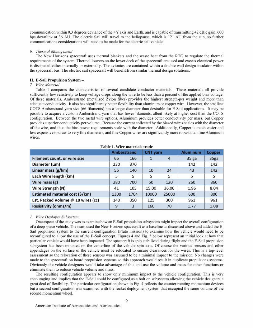
Table 1 compares the characteristics of several candidate conductor materials. These materials all provide sufficiently low resistivity to keep voltage drops along the wire to be less than a percent of the applied bias voltage. Of these materials, Amberstrand (metalized Zylon fiber) provides the highest strength-per weight and more than adequate conductivity. It also has significantly better flexibility than aluminum or copper wire. However, the smallest COTS Amberstrand yarn size (66 filaments) has a larger diameter than desirable for E-Sail applications. It may be possible to acquire a custom Amberstrand yarn that has fewer filaments, albeit likely at higher cost than the COTS configuration. Between the two metal wire options, Aluminum provides better conductivity per mass, but Copper provides superior conductivity per volume. Because the current collected by the biased wires scales with the diameter of the wire, and thus the bias power requirements scale with the diameter. Additionally, Copper is much easier and less expensive to draw to very fine diameters, and fine Copper wires are significantly more robust than fine Aluminum wires.
Table 1. Wire materials trade
Amberstrand CNT yarn Aluminum Copper Filament count, or wire size 66 166 1 4 35 ga 35ga Diameter (µm) 230 370 142 142
Linear mass (g/km) 56 140 10 24 43 142 Each Wire length (km) 5 5 5 5 5 5 Wire mass (g) 280 700 50 120 260 860 Wire Strength (N) 41 105 15.00 36.00 1.96 8.04 Estimated material cost ($/km) 1300 1704 10000 25000 600 800 Est. Packed Volume @ 10 wires (cc) 140 350 125 300 961 961 Resistivity (ohms/m) 9 3 160 70 1.77 1.08
1. Wire Deployer Subsystem
One aspect of the study was to examine how an E-Sail propulsion subsystem might impact the overall configuration of a deep space vehicle. The team used the New Horizon spacecraft as a baseline as discussed above and added the E-Sail propulsion system to the current configuration (Pluto mission) to examine how the vehicle would need to be reconfigured to allow the use of the E-Sail concept. Figures 4 and Fig. 5 below represent an initial look at how that particular vehicle would have been impacted. The spacecraft is spin stabilized during flight and the E-Sail propulsion subsystem has been mounted on the centerline of the vehicle spin axis. Of course the various sensors and other appendages on the surface of the vehicle must be relocated to ensure clearances for the wires. This is a top-level assessment so the relocation of these sensors was assumed to be a minimal impact to the mission. No changes were made to the spacecraft on board propulsion systems so this approach would result in duplicate propulsions systems. Obviously the vehicle designers would take advantage of this and use the volume and mass for other functions or eliminate them to reduce vehicle volume and mass.
The resulting configuration appears to show only minimum impact to the vehicle configuration. This is very encouraging and implies that the E-Sail could be configured as a bolt on subsystem allowing the vehicle designers a great deal of flexibility. The particular configuration shown in Fig. 4 reflects the counter rotating momentum devices but a second configuration was examined with the rocket deployment system that occupied the same volume of the second momentum wheel.

American Institute of Aeronautics and Astronautics
10
Figure 4. New Horizon spacecraft with an E-sail propulsions system mounted below the antenna system.
Figure 5. New Horizons spacecraft with
wires partially deployed.
The following figures (Fig. 6 and Fig. 7) show how the vehicle configuration will work with the rocket deployment
system. Again the basic configuration is very similar to the one shown above but now two small rockets are used to deploy groups of wires and then the rockets are used to fan out the wires.
Figure 6. Vehicle configuration is shown with the rocket deployment system.
Figure 7. Vehicle configuration with wires deployed.
Deployment Concept of Operations (CONOPS)
The basic E-Sail deployment concept however, presents two significant technical challenges. To ensure the wires stay aligned mostly perpendicular to the solar wind (rather than being blown behind the spacecraft), the centrifugal tension on the wire should be roughly a factor of five times the solar wind force. This requires a spin rate on the order of once per hour, which, while slow, requires that the system provide a very large amount of angular momentum to the E-Sail structure. For a multi-kilometer wire length, a simple deployment scheme where the spacecraft is first spun up and then the wires allowed to unspool outward under centrifugal force is not viable because the initial spin rate required to provide the necessary final spin rate once the wires are deployed would be many millions of revs per second.
I. Deployment Approach Previously Developed By Dr. Janhunen Second, because the forces on the individual wires are likely to vary depending upon orientation to the solar wind
as well as due to local variations in solar wind speed, density, and direction, their rotation rates around the central spacecraft will vary, and so it is necessary to provide a means to ensure the lines remain separated and do not collide or tangle. Dr. Janhunen’s original concept proposed the use of continuous controlled variation of each wire’s length to maintain constant rotation rates. However, this method introduces significant system complexity and would require the wires to be continually reeled in and out, which may be problematic for a multi-line wire that will experience multiple cuts to its individual lines during its lifetime.

American Institute of Aeronautics and Astronautics
11
To simplify the concept, Dr. Janhunen proposed connecting the ends of each wire line to its two adjacent lines using non-conducting ‘auxiliary wires’ strung around the circumference, as illustrated in Fig. 8.14. At the end of each of the primary wires, a “Remote Unit” sub-satellite would be used to deploy both the main wire and the auxiliary wires. Thrusters on these remote units could accomplish the spin-up of the E-Sail system. While technically feasible, this approach presents several drawbacks. First, deployment and spin-up of the system would require tightly coordinated thrust operations of the multiple Remote Unit as well as coordinated operation of all of the multiple wire deployers on the Remote Units. Additionally, the mass of these multiple Remote Units, each with three wire deployers and multiple thrusters will reduce the thrust-to-mass performance of the E-Sail system.
Figure 8. E-sail with auxiliary wires to maintain
separation between radial wires. While Dr. Janhunen’s concept is technically feasible, it has high complexity, requiring successful, coordinated
operation of a very large number of mechanisms to achieve deployment and spin-up of the E-Sail system.
J. “Chinese Fan” Deployment CONOPS Here we propose a new deployment CONOPS that can potentially significantly reduce the complexity and mass
of the hardware required to deploy and spin-up the E-Sail structure. In this concept, the E-Sail wire configuration is similar to Dr. Janhunen’s ‘flower-petal’ concept, except that one pair of adjacent primary wires are not connected by an auxiliary wire, so that it has a structure similar to a Chinese Fan, as illustrated on the left in Fig. 9. Instead, a ‘Crawler’ mechanism is initially positioned at the spacecraft end of those two wires. The E-Sail structure can then be folded by pulling the center of each auxiliary wire in the direction perpendicular to the E-Sail’s plane, resulting in a linear bundle of wires as illustrated on the right in Fig. 9. This bundle of wires and auxiliary wires can then be wound on a spool in a single deployer. Fig. 10. illustrates how then the E-Sail structure would then be deployed by a single sub-satellite, with thrusters on either the deployer subsatellite or the main spacecraft ensuring the wires remain taut as the structure is deployed.

American Institute of Aeronautics and Astronautics
12
Figure 9. Concept for stowage of the e-sail structure as a single bundle of wires.
Figure 10. Concept for deployment of the e-sail structure from a single deployer.
Once the full length of the wires is deployed, the deployer sub-satellite would thrust perpendicular to the wire
orientation so as to set the system in rotation, as illustrated in Fig. 11.
Figure 11. Concept for spin-up of the e-sail structure with a single sub-satellite.
Once the system reaches the desired rotation rate, the deployer would release all of the auxiliary lines except for one at the edge of the ‘Chinese Fan’ structure, and the sub-satellite would continue to thrust (at low thrust levels) so as to spread out the fan into a full circle, as illustrated in Fig. 12. The primary vehicle would likely need to perform some thrusting and attitude control to ensure it does not become tangled in the wire lines. Having completed its duties, the deployer sub-satellite could then release from the E-Sail wires so that its mass does not impact the E-Sail performance. To complete the structure, the ‘Crawler’ vehicle would then slide out along the two edge wire lines, under the force of centrifugal acceleration and, if necessary, assisted by simple pinch roller mechanisms, as illustrated in Fig. 13, constraining the two edge wires together and completing the circular E-Sail structure.

American Institute of Aeronautics and Astronautics
13
Figure 12. Concept for spreading the radial lines apart.
Figure 13. The crawler system would then crawl/slide out along the two edge wires to ‘sew’ the structure into a circle.
Advantages of this deployment approach are that the multi-wire structure can be assembled in a straightforward
manner as the wires are wound onto the deployer spool, and the number of radial wires can readily be increased without requiring additional deployer hardware.
All of the hardware necessary to deploy this E-Sail structure has high technical maturity. Figure 14 shows a 1.5U scale wire deployer that TUI developed for the MAST CubeSat experiment. In this deployer, the wire is wound around a spool with 1 twist per turn, so that it can then be pulled off of the end of the spool with no net twist imparted. This type of deployer can be scaled readily. Based upon prior experience, we estimate that a deployer sized to hold a structure with 50, 10-km long Amberstrand-66 wires and the required auxiliary wires will have a diameter of approximately 40 cm and a height of approximately 70 cm.
K. “Momentum Wheel” Deployment CONOPS The momentum deployment method uses existing Control Moment Gyroscope (CMG) hardware with the wires
installed on one wheel and the other wheel has a combination spin up motor/generator (Fig. 15) wheels are initially spun up to manageable levels and then the wires are partially deployed. Once the wires are deployed a short distance (0.5 to 1 km) the system begins to manage the angular momentum by alternatively slowing adding angular momentum to the wires and then removing momentum from the second wheel by producing electrical power. The process must be carefully managed in order that the angular momentum added does not accelerate the wheels without accelerating the wires and maintain the centrifugal acceleration on each wire. The idea is to keep the second wheel from being accelerated to very high rotations.
Figure 14. Wire deployer developed for the MAST CubeSat experiment.
Figure 15. Momentum managed deployment concept.

American Institute of Aeronautics and Astronautics
14
VII. E-Sail Propulsion System TRL Assessment of Subsystems An engineering team was assembled to assess the technology of the required subsystems (Table 2) in order to
develop a plan for future work. Current Technology Readiness Levels (TRL) of individual component technology (deployable wires, solar panels, electron gun, and satellite bus etc.) is generally at a TRL of 8 or 9 for each component, but when combined into the overall E-Sail system the TRL is very low due to the uncertainties dictating how each subsystem will interact with the others. The study was focused on identifying critical systems and components that will require immediate resources to increase the TRL of the total system. Current and near term efforts are focused on the high risk areas denoted by an asterisk in Table 2.
The team that was assembled to conduct this study was asked to consider the electric sail as a system, and identify the one or two most critical elements that their discipline would be asked to provide. Once all sub-system elements were identified, the team again assessed the system in its entirety. The discipline experts on the team chose the items they felt are the most critical for the system, and in need of the most resources to advance the cumulative TRL of the system. The group as a whole identified the systems most in need of development. The subsystems identified as high priority areas of research are:
1) A deeper understanding of the physics behind proton interaction and the spacecraft; 2) The environment surrounding the elimination of electrons from the system; 3) Guidance, navigation and control; and 4) The mechanical deployment of the wire sail.
VIII. Comparison of Alternative In-Space Propulsion Systems A comparison of propulsion concepts was taken from the Interstellar Probe study performed by the ACO for the
Keck Institute for Space Studies (KISS) in which many team members participated. This study compared known or near term low-thrust advanced propulsion system candidates while determining which SLS configuration could deliver the appropriate characteristic energy (C3) to the spacecraft based on several trajectory options. The candidate propulsion systems were: 1) Magnetically Shielded Miniature (MaSMi) Hall thruster (Fig. 16), 2) Solar Sail (Fig. 17) and 3) E-Sail (Fig. 18). Several possible trajectories were studied involving both single- and multiple-planetary flyby maneuvers to understand if any additional “free” energy could be obtained to boost the speed of the spacecraft toward interstellar space.
Table 2: Critical subsystem identified by design team.

American Institute of Aeronautics and Astronautics
15
Figure 16. MaSMi Hall thruster system.
Figure 17. Solar Sail propulsion system.
Figure 18. Electric Sail
propulsion ystem.
L. Alternative Propulsion Assumptions Several low-thrust Advanced Ppropulsion System (APS) technologies were traded for each of the trajectory profiles
considered, including a MaSMi Hall thruster, solar sails and an E-Sail propulsion system. In addition to the spacecraft having some kind of onboard low-thrust APS stage, the required quantity and size of aft-attached, series-burn SRM kick stages for various impulsive maneuvers was also assessed. The MaSMi hall thruster, would be powered by the onboard eMMRTG outputting 450 W of power; and, it was assumed to be capable of 50,000 hours of maximum lifetime and exerting 19 mN (0.004 lbf) of thrust with an Isp of 1,870 seconds. The solar sail and E-Sail propulsion system Ground Rules and Assumptions (GR&A) are outlined below in Tables 3 and 4, respectively.
Table 3. Solar sail propulsion system GR&A. Item Description
Reflectivity 0.91
Minimum Thickness 2.0 μm
Maximum Size (per side) 200 m (656 ft)
Sail Material CP1
Aerial Density * 3 g/m2 10 g/m2
Characteristic Acceleration 0.426 mm/s2 0.664 mm/s2
System Mass 120 kg (265 lbm) 400 kg (882 lbm) * Assumes an advancement in technology. Current technology is approximately 25 g/m2.
Table 4. Electric Sail (E-Sail) propulsion system GR&A. Item Description
System Mass 120 kg (265 lbm)
Wire Material (Density) Aluminum (2,800 kg/m3)
Wire Diameter (Gauge) 0.127 mm (36 gauge)
Characteristic Acceleration 1 mm/s2 2 mm/s2
Tether Quantity 10 20
Individual Tether Length 20 km (12.4 mi) 20 km (12.4 mi)
IX. Mission Design E-Sail technology is a high performance propulsion system that allows demanding missions that are not feasible
with other propulsion technologies. However the E-Sail cannot point in any arbitrary direction. Since the direction the

American Institute of Aeronautics and Astronautics
16
resulting thrust force can be pointed in is restricted, the best mission fit for this technology is one that does not require multiple pointing angles.
The Design Reference Mission (DRM) for the E-Sail is the Heliopause mission. The primary goal of this mission is to reach the Heliopause (considered to be the boundary of the solar system at ~ 100 AU) as soon as possible. This mission requires the E-Sail to be at the same angle for the most of the mission, and when it does change, it changes slowly. Since the E-Sail has constraints on both the ability to point and maneuverability of the sail, the Heliopause mission is well-suited to E-Sail technology.
A figure of merit for the performance of an E-Sail is Characteristic Acceleration, a parameter borrowed from solar sails. The Characteristic Acceleration is defined as the acceleration achieved when the E-Sail spacecraft is pointed directly at the Sun (i.e., the sail plane is normal to the Sun vector) at 1 AU. Characteristic Acceleration values for preliminary designs of E-Sails have been published by Dr. Janhunen in several references. Quarta and Mengali8 build on his work and present mission design results for a range of characteristic accelerations from 0 to 2 mm/sec2 where 2 mm/sec2 is considered the upper end of the performance range based on previous work by Dr. Janhunen. By contrast, 0.5 mm/sec2 is considered a high level of performance for a solar sail. For the purposes of this mission design study, we chose 1 mm/sec2 and 2 mm/sec2 as “nominal” and “high performance” E-sail Characteristic Accelerations.
M. Trajectory Profile Analysis Two trajectory profiles were considered for this study: (1) an escape trajectory using a Jupiter Gravity Assist
(JGA) maneuver (E-Ju) and (2) an escape trajectory first performing a JGA maneuver followed by a sun dive via an impulsive Oberth maneuver and Saturn gravity assist maneuver (E-Ju-Su-Sa). Both trajectory profiles are depicted in Fig. 19 and are separated based on the type of low-thrust APS employed.
Figure 19. Mission Design Trajectory Profiles Examined

American Institute of Aeronautics and Astronautics
17
1. An Escape Trajectory Using A Jupter Gravity Assist Maneuver
The trajectory relies more heavily on the SLS C3 capability which sets the spacecraft’s initial velocity prior to earth departure. To depart earth’s sphere of influence, the spacecraft performs an impulsive ΔV burn via a SRM kick stage and then at 1 AU from the center of the sun deploys and activates its low-thrust APS at a tangential velocity corresponding to a set C3 value. Depending on the type of APS deployed, upon activation, either: 1) the MaSMi Hall thrust system remains active until its assumed 50,000-hour maximum lifetime is reached, 2) the Solar Sail system is jettisoned prior to the Jupiter flyby, or 3) the E-Sail system is jettisoned when it reaches a point of diminishing return, estimated to occur at about 20 AU into the trajectory. The spacecraft approaches Jupiter and performs a JGA flyby maneuver at a distance of 4.89 Jupiter radii assuming Jupiter’s orbit is circular at 5.203 AU from the center of the sun. Figures 20 and 21 illustrate the effect of each low-thrust APS type on the total trip time to the heliopause at 100 AU. Two E-Sail data points are plotted in Figure 15 denoted by , which corresponds to an E-Sail characteristic acceleration of 2 mm/s2, and , which corresponds to a 1 mm/s2 characteristic acceleration.
Figure 20. Low-thrust APS analysis for E-Ju trajectory profile.
Figure 21. E-Sail propulsion system analysis for E-Ju trajectory profile.
2. An Escape Trajectory Using A JGA Maneuver Followed by An Impulsive Oberth Maneuver Then A Saturn Gravity Assist Maneuver
Similar to the first trajectory option, the second trajectory begins by having the spacecraft perform an impulsive ΔV burn via a SRM kick stage in order to depart the earth’s sphere of influence. While the low-thrust APS is still inactive, the spacecraft then performs a JGA flyby except this time at a distance of 18.72 Jupiter radii away, which reduces the perihelion approach to just 11 solar radii, or approximately 0.05 AU. At perihelion, about 2.97 years into the mission, another SRM kick stage performs the second and final impulsive ΔV burn via an Oberth maneuver but is not jettisoned along with the heat shield until 0.5 AU after perihelion passage. Approaching this close

American Institute of Aeronautics and Astronautics
18
to the sun requires that the spacecraft’s heat shield withstand temperatures upwards of 2,500 °F. The low-thrust APS is deployed and activated at 0.1 AU and, again depending on which APS is employed, similar to the first trajectory option, it will either be left on or jettisoned upon the spacecraft’s approach to Saturn. The MaSMi Hall thruster system would remain active until its assumed 50,000-hour maximum lifetime is reached, the Solar Sail system would be jettisoned prior to the Saturn flyby, or the E-Sail system would be jettisoned when it reaches a point of diminishing return as it pursues 100 AU from the center of the sun. The spacecraft then performs a Saturn gravity assist flyby maneuver at a distance of 2.67 Saturn radii away assuming Saturn’s orbit is circular and at 9.583 AU.
Figure 22 below describes how the performance capability of the SRM kick stage chosen for the Oberth impulsive ΔV maneuver affects the total trip time to 100 AU, where corresponds to an E-Sail characteristic acceleration of 1 mm/s2. Figure 23 provides additional insight into the E-Sail trajectory for option 2 previously shown in Fig. 19 above, at E-Sail characteristic Accelerations of 1 mm/s2 and 2 mm/s2.
Figure 22. Kick stage analysis for E-Ju-Su-Sa trajectory profile.
Figure 23. Kick stage analysis for E-Ju-Su-Sa trajectory profile (E-Sail only).
X. Conclusions Conceptual analysis concludes that a spacecraft could reach interstellar space within a noticeably shorter amount
of time compared to the 36 years it took Voyager 1 when employing low-thrust Advanced Propulsion System (APS) stages. In fact, applying an E-Sail low-thrust APS stage results in the lowest total trip time of approximately 10 years for the E-Ju trajectory option as shown in Fig. 24.
All low-thrust APS technologies for either trajectory option provide substantial total trip time improvements over the previous Voyager missions with outbound trip times ranging anywhere from 10 – 19 years, assuming a maximum applied C3 capability of 135 km2/s2 for an E-Ju- trajectory profile or an average perihelion kick stage ΔV of 3 km/s (9,842 ft/s) for the E-Ju-Su-Sa trajectory profile. However, for the latter profile, compared to the MaSMi Hall thruster and Solar Sail propulsion systems, having no low-thrust APS stage actually achieves almost the same total trip time especially for perihelion kick stage ΔV’s greater than 4 km/s (13,123 ft/s).
It is worth noting that there is one concern specifically for the E-Ju-Su-Sa trajectory option and that is the SRM-powered Oberth maneuver performed very close to the sun’s surface at 11 solar radii or 0.05 AU. Keeping in mind

American Institute of Aeronautics and Astronautics
19
that this is a conceptual study, the assumed heat shield technology is stemming from NASA’s Solar Probe Plus mission, which is scheduled to occur before the Interstellar Probe mission. It is uncertain as to how the heat shield would cover the SRM kick stage performing the impulsive perihelion burn while not being simultaneously partially destroyed by the kick stage’s plume. In other words, if the heat shield incurs damage then it is a concern as to how the rest of the shield would perform for the duration of the trajectory where the spacecraft is still very close to the sun.
Figure 24. Time to 100 AU for various propulsion systems
XI. Recommended Future Steps towards E-Sails in Space A review of the observations and findings from earlier sections indicates there are four areas that present significant
challenges to the development of the E-Sail propulsion system. These four areas include: 1) Understanding the interaction of the protons and the biased wire sheath 2) Understanding and validating the net thrust on the deployed conductors/wires 3) Deployment of the long-thin wires and control of these wires during operational phases 4) Vehicle control when voltages and forces are varying on individual wires.
These four areas represent the most significant risk or challenges to the development program. The remaining subsystems such as the electron emission source or electron gun, high voltage power supplies and voltage control devices are expected to be derivative of existing hardware. In fact, the high voltage power supplies are expected to be very similar in design to those being developed for the next generation electric propulsions systems.
The recommended approach for understanding the interaction of the protons and resulting sheath/wires is to perform additional chamber testing. Prior testing performed at MSFC in the 1980’s provided the enhanced understanding of the electron/proton interaction with charged bodies in space. This provided the team with the data to conclude the actual thrust being proposed originally for the E-Sail by Dr. Pekka Janhunen was understated. Thogh this original testing was performed on relatively large spheres and there is concern on how the small diameter wires will perform.
Particle-in-cell (PIC) modeling is key to understanding how the system will perform in deep space. Testing of long conductors is in-practical on the ground so combining a multistep program where PIC models are verified by the plasma testing and then used to extrapolate to deep space environments. These PIC models will be a key tool to support the design of the E-Sail.
Deployment of the wires was considered a very complex task and while numerous good ideas were examined most were considered too complex to be practical. The team discussed numerous approaches including those presented by our FMI collaborator Dr. Pekka Janhunen. Only two configurations were selected to go forward based on complexity and the ability to provide a mass efficient design. There are several other approaches that remain as second tiers that could be brought forward if neither of the two concepts selected are successful. The two concepts selected to go forward were both simple and minimized new hardware developments.
The rocket deployed approach built on previous Tethers Unlimited Incorporated (TUI), a study partner, experience with long tethers in space. The momentum management approach builds on Control Moment Gyroscopic (CMG)
American Institute of Aeronautics and Astronautics
20
devices that allow a spacecraft to manage the angular momentum with opposing wheels. This is much like power storage concepts developed in the late 90’s for energy storage where a pair of opposing wheels would be spun to store electrical power that would be retrieved by reversing the electrical motors and using them as generators. No real ground test can be conducted with long wires to test deployment concepts so high fidelity simulations are required. The use of an existing tether simulation program from TUI called Tether-Sim provides a basis for developing these simulations and assessing the deployment concepts in some detail.
These same simulations will allow the team to assess the wires once fully deployed and operating. The forces on the individual wire including the thrust, and centrifugal acceleration will be assess to ensure there are no unforeseen motions such as skip roping seen on the near-earth tethers systems.
The previous European studies led bt Dr, Janhunen identified some concerns with vehicle control due to the forces varying from wire to wire. Tacking the vehicle or varying the voltages on individual wires could cause the wires to come in contact with each other. This contact is undesired and must be avoided. Further there are no control laws developed for such a vehicle. These control laws and approaches to managing the wires are a concern to the team. The recommended approach to developing the control strategies and understanding how the vehicle will be steered will require the use of additional simulations. These simulations should build on those performed under the phase I efforts here.
A roadmap for the development of the E-Sail is being to become clear. Obviously the first step is to develop the data and simulations discussed above. These simulations will provide the design data required to develop any scale propulsion system. Clearly, a demonstration flight is required to reduce the risk for larger scale programs. Several Cubesat demonstration flight concepts have been developed and should be practical to fly in the 2018-2020 timeframe. These demonstration flights would allow the team to obtain the data and knowledge to retire the most significant risk issues.

American Institute of Aeronautics and Astronautics
21
References 1Mengali, G., A. Quarta and P. Janhunen, Electric sail perfromance analysis, J. Spacecr. Rockets, No. 45, pp.122-129, 2008. 2Mengali, G. and A. Quarta, Non-Keplerian orbits for electric sails, Cel. Mech. Dyn. Astron., No. 105, pp. 179-195,
doi:10.1007/s10569-009-9200-y, 2009. 3Quarta, A.A. and G. Mengali, Electric sail missions to potentially hazardous asteroids, Acta Astronaut., No. 66, pp. 1506-
1519, 2010. 4National Research Council: Solar and Space Physics: A Science for a Technological Society, 2012
Solar and Space Physics: A Science for a Technological Society, 2012 5http://interstellar.jpl.nasa.gov/ 6 NASA Technology Roadmaps TA 2: In-Space Propulsion Technologies, Draft ed., May 2015, Section 2.3.2 Electric Sail
Propulsion. 7Janhunen, P.: Electric Sail for Spacecraft Propulsion, J. Propul. Power, 20(4), pp. 763-764, 2004. 8Quarta, A.A. and G. Mengali, Electric sail mission analysis for outer solar system exploration, J. Guid. Contr. Dyn., No. 33, 740-755, 2010. 9Stone, N. H., The Aerodynamics of Bodies in a Rarefied Ionized Gas With Applications to Spacecraft Environmental
Dynamics, NASA Technical Paper 1933, pp. 97-102, November 1981. 10Janhunen, P.: Electric Sail for Spacecraft Propulsion, J. Propul. Power, 20(4), pp. 763-764, 2004. 11Stone, N. H., B. J. Lewter, W. L. Chisholm, and K. H. Wright, Jr., Instrument for differential ion flux vector measurements
on Spacelab 2, Review of Scientific Instruments, 56 No. 10, October 1985. 12Glen H. Fountain, David Y. Kusnierkiewicz, Christopher B. Hersman, Timothy S. Herder, Thomas B Coughlin, William T.
Gibson, Deborah A. Clancy, Christopher C. DeBoy, T. Adrian Hill, James D. Kinnison, Douglas S. Mehoke, Geffrey K. Ottman, Gabe D. Rogers, S. Alan Stern, James M. Stratton, Steven R. Vernon, Stephen P. Williams, The New Horizons Spacecraft; Space Science Reviews Volume 140, Issue 1-4 , pp 23-47 (2007).
13“Enhanced Multi-Mission Radioisotope Thermoelectric Generator (eMMRTG) Concept,” NASA. https://solarsystem.nasa.gov/rps/docs/eMMRTG_onepager_LPSC20140317.pdf
14Janhunen, P., et al., Invited Article: Electric solar wind sail: Toward test missions,” Rev. Sci. Instr. 81, 111301 (2010).