flight simulation year in review fy98
TRANSCRIPT

Flight SimulationYear in Review
FY98
Aviation Systems Research, Technology, & Simulation Division 1

Foreword
Aviation Systems Research,Technology, & Simulation Division
NASA Ames Research CenterMoffett Field, California 94035
11 December 1998
This document is the Fiscal Year1998 Annual Performance Summary ofthe NASA Ames Vertical Motion Simula-tion (VMS) Complex and the CrewVehicle Systems Research Facility(CVSRF). It is intended to report to ourcustomers and management on themore significant events of FY98. Whatfollows are an Executive Summary withcomments on future plans, the FY98Simulation Schedule, a projection ofsimulations to be performed in FY99,performance summaries that report onthe simulation investigations conductedduring the year, and a summary ofTechnology Upgrade Projects.

4 Aviation Systems Research, Technology, & Simulation Division
Acknowledgment
About the Cover
Front cover: The Advanced Concepts Flight Simulator examined a new flight system with the potential toimprove the safety and efficiency of airport surface operations in low visibility. This cockpit navigation andguidance system displays taxi routes on both a head-up display (pictured) and an electronic moving map.Taxi runs made with the system were rapid and error free. (For more information, see page 35.)
Back cover: The Vertical Motion Simulator has a key role in the development of the next-generation fighter,which will be flown by three branches of the U.S. military. Two proposed versions of the Joint Strike Fighterwere simulated: Boeing’s X-32 (left) and Lockheed Martin’s X-35 (right). (For more information, see pages 16and 19.)
Special thanks to Matt Blake, Dave Carothers, Girish Chachad, Bill Chung, Ron Gerdes, Scott Gilliland,Jennifer Goudey, Scott Malsom, Julie Mikula, Bob Shiner, and Barry Sullivan for contributions made to theproduction of this document.
Aviation Systems Research, Technology, & Simulation Division 5
Table of Contents
Foreword ............................................................................................................................................ 3Executive Summary .............................................................................................................. ........... 6FY98 Simulation Schedule ................................................................................................................ 9FY98 VMS Project Summaries ........................................................................................................ 10FY98 CVSRF Project Summaries .................................................................................................... 11FY99 VMS Simulation Projects ........................................................................................................ 12FY99 CVSRF Simulation Projects.................................................................................................... 13Vertical Motion Simulator Research Facility ............................................................................... 15
Boeing B1, A1, A2......................................................................................................................... 16Simulation Fidelity Requirements 5 .............................................................................................. 17Civil Tiltrotor 7 ............................................................................................................................... 18Lockheed Martin ........................................................................................................................... 19Space Shuttle Vehicle 1 ................................................................................................................ 20Helicopter Maneuver Envelope Enhancement 5 .......................................................................... 21Slung Load 5 ............................................................................................................................... 22Simulation Fidelity Requirements 6 .............................................................................................. 23High Speed Civil Transport Design & Integration ......................................................................... 24High Speed Civil Transport A7...................................................................................................... 25High Speed Civil Transport A7B ................................................................................................... 26Partial Authority Flight Control Augmentation ............................................................................... 27Space Shuttle Vehicle 2 ................................................................................................................ 28
Crew-Vehicle Systems Research Facility .................................................................................... 31Decision Making ........................................................................................................................... 32Propulsion Controlled Aircraft 3 .................................................................................................... 33Obstacle Free Zone 1, 2 ............................................................................................................... 34Taxiway Navigation and Situation Awareness .............................................................................. 35Air-Ground Integration (Free Flight 3) .......................................................................................... 36Turbulence for Precipitous Terrain ................................................................................................ 37Fatigue Countermeasures ............................................................................................................ 38Propulsion Controlled Aircraft 4 (Ultralite) .................................................................................... 39Advanced Automation Qualification .............................................................................................. 40
Technology Upgrade Projects .................................................................................................... .. 43Virtual Laboratory ......................................................................................................................... 44Out-the-Window 2000 Plus ........................................................................................................... 45Host Computer Upgrade ............................................................................................................... 46Real-Time Network Upgrade ........................................................................................................ 47Bosnia Visual Database ............................................................................................................... 48Joint FAA/Army/NASA Interoperability Demonstration ................................................................. 49Flight Management System Upgrade ........................................................................................... 50Communications System Upgrade ............................................................................................... 51
List of Acronyms ............................................................................................................... ............. 52Appendix 1 ..................................................................................................................... ................. 54
6 Aviation Systems Research, Technology, & Simulation Division
Executive Summary
This Annual Report addresses the major simulation accomplishments of the AviationSystems Research, Technology, and Simulation Division of the NASA Ames ResearchCenter. The Ames Simulation Facilities, contained in two separate buildings at AmesResearch Center and operated by this Division, consist of the Crew Vehicle SystemsResearch Facility (CVSRF) and the Vertical Motion Simulation (VMS) Complex. TheCVSRF is comprised of a Boeing 747-400 Simulator, the Advanced Concepts FlightSimulator (ACFS), and an Air Traffic Control (ATC) simulator. The VMS Complex iscomprised of the Vertical Motion Simulator (VMS), five Interchangeable Cockpits (ICABs),and two fixed-base simulation labs. A brief description of these facilities follows this reportin Appendix 1.
From a Management perspective, Fiscal Year 1998 was dominated by several impor-tant events. First was the achievement of ISO 9001 Certification in May. This certificationwas achieved after two years of planning and effort by the entire staff, civil service andcontractor. A second significant event was the organizational transition completed in Julywith the forming of the new Aviation Systems Research, Technology, and SimulationDivision (AF). This completes the changes begun when the Wind Tunnels became aseparate Division within Code F. The final activity has been the continuing efforts tostreamline and reduce facility operations costs at NASA.
In addition to these activities, paramount to Division operations has been the continu-ing commitment to uncompromised excellence in the development and production ofefficient, high-fidelity, safe, real-time piloted flight simulations. The Division has alsocontinued to aggressively modernize in order to maintain reliability, our competitive edge,and our responsiveness to Users’ needs. The staff places very high value on customerrelations and has successfully provided highly responsive, cost-effective, value-addedsimulation support to all simulation customers.
The purpose of this document is to briefly describe our accomplishments of the pastyear. Its outline includes the Executive Summary, Simulation Schedule for FY98, PlannedProjects for FY99, VMS Project Summaries, CVSRF Project Summaries, and TechnologyUpgrade Projects. The Project Summaries sections state the goal of each simulation andpresent high level results. Researchers and Pilots from NASA and private industry areidentified as well as simulation engineers from the staff. The Technology UpgradeProjects section reports changes made in order to keep our simulation facilities state-of-the-art. Finally, a List of Acronyms is included for the reader’s convenience.Notable accomplishments for FY98 include the following:
All simulation experiments conducted at Ames support significant research that isresponsive to the needs of the Nation with a focus on applied aeronautics research.Diversity, fidelity, and breadth of simulation distinguish the research projects conducted atAmes, as can be seen by reviewing the Project Summaries sections of this report.
There were 26 major simulation experiments conducted in the flight simulation labora-tories in FY98. These simulations reflect a continued concentration on NASA’s focusedprograms such as High Speed Research (HSR), Advanced Subsonic Technology (AST),NASA’s Space Operations, and FAA/NASA Airspace Operations Systems. Support wasalso provided to other Government research, with emphasis on the Army Rotorcraft andJoint Strike Fighter (JSF) programs. In addition, there were several technology upgradeprojects either completed or with significant progress being accomplished during the year.
Aviation Systems Research, Technology, & Simulation Division 7
A. David Jones
Associate Chief-SimulationsAviation Systems Research, Technology, & Simulation Division
Technology upgrade projects for the past year include:Within the CVSRF, upgrades to the ACFS Flight Management System and the
facilitywide Communications System were completed. An evaluation of the application ofthe DOD High Level Architecture was also performed in coordination with the Army andFAA.
The VMS completed the conversion to the new ESIG 4530 with the expansion to fivechannels and its routine use in production operations. In addition, incremental upgradesto the Host Computer systems and the Virtual Laboratory were completed.Some future plans:
All of the simulation facilities continue to be in high demand. There is a full list ofprojects for FY99 that build on past research efforts and bring some new activities aswell. We will continue our tradition of supporting mainstream NASA and national aeronau-tical development programs, being second to none in state-of-the-art real-time simulationand enabling technologies. Automated tools for simulation and modeling, improvementsin graphics and displays, and efficient computational environments are other continuingefforts.
In addition, significant efforts are underway planning the VMS Modernization Projectcurrently scheduled for FY01. The project will replace obsolete mechanical drives andcontrol equipment with state-of-the-art systems. When complete, the VMS will set thestandard for low-cost, reliable, high-performance motion.

8 Aviation Systems Research, Technology, & Simulation Division

79'tc
O79'
vo
N79'
ceD
89'naJ
89'be
F89'
raM
89'r
pA
89'ya
M89'
en
uJ89'
yluJ
89'g
uA
89't
peS
89'tc
O6
3102
723
0171
421
851
2292
521
9162
29
6132
29
6132
036
3102
724
1181
521
851
2292
631
0272
301
7142
137
4112
825
2191
62
Sim
ulat
ion
Exp
erim
ents
Bra
nch
Avi
atio
n S
yste
ms
Res
earc
h,Te
chno
logy
, & S
imul
atio
n D
ivis
ion
Am
es R
esea
rch
Cen
ter
FY
98 S
imul
atio
n S
ched
ule
Sim
ulat
ion
Fac
ilitie
s
VM
SS
hift
A
I-C
ab F
ixed
Bas
e
Shi
ft B
B74
7
ACFS
Shi
ft A
Shi
ft B
ATC
Aviation Systems Research, Technology, & Simulation Division 9
DE
CT-
NA
SA
CTA
S F
MS
NA
SA
NA
SA
NA
SA
T-N
AS
AP
CA
4C
TAS
FM
S
NA
SA
NA
SA
NA
SA
Air-
Gro
und
OF
Z 2
OF
Z 1
PC
A 3
DE
CP
reci
pito
us T
erra
in
Fat
igue
Cou
nt.
AA
Q
NA
SA
FAA
FAA
NA
SA
NA
SA
FAA
NA
SA
NA
SA
Mot
ion
Tuni
ngB
OE
ING
B
1
A
1S
IMF
R 5
CT
R 7
LOC
KH
EE
DS
SV
HE
LME
E S
LOA
DS
IMF
R 6
BO
EIN
G
A2
HS
CT
D&
IH
SC
T A
7P
AF
CA
SS
V 2
LAS
CA
SH
SC
T A
7B
NA
SA
Boe
ing
NA
SA
NA
SA
NA
SA
NA
SA
, JS
C,
Roc
kwel
lN
AS
AA
rmy
NA
SA
NA
SA
Boe
ing
NA
SA
, Boe
ing,
Hon
eyw
ell
NA
SA
, Boe
ing
NA
SA
,A
rmy
NA
SA
, JS
C,
Roc
kwel
lA
rmy,
Hoh
NA
SA
Arm
yN
AS
A,
Boe
ing
HS
CT
A7,
D&
IH
ELM
EE
5LA
SC
AS
NA
SA
, Boe
ing
NA
SA
, Arm
yA
rmy,
Hoh
CT
R 7
LOC
KH
EE
DB
OE
ING
A2
HS
CT
D&
IP
AF
CA
BO
EIN
G B
2
NA
SA
NA
SA
NA
SA
,B
oein
gN
AS
A, B
oein
g,H
oney
wel
lN
AS
A, A
rmy
NA
SA
,B
oein
g
Air-
Gro
und
NA
SA
10 Aviation Systems Research, Technology, & Simulation Division
VMS Flight Simulation Projects1. Boeing B12. Boeing A13. Boeing A2Sept 1 - 11, May 1 - 4 (FB);Sept 22 - Oct 17, Oct 20 - 31, May 11 - 29 (VMS)Aircraft type: X-32 Joint Strike FighterPurpose: To support Boeing’s design and develop-ment process and to further NASA-sponsoredresearch of short takeoff/vertical landing controls.
4. Simulation Fidelity Requirements 5 (SimFR 5)Nov 3 - 20 (VMS)Aircraft type: NT-33Purpose: To evaluate the effectiveness of simulatormotion in predicting pilot-induced oscillation.
5. Civil Tiltrotor 7 (CTR 7)Nov 3 - 20 (FB); Nov 24 - Dec 18 (VMS)Aircraft type: Civil TiltrotorPurpose: To investigate aircraft guidance, terminalflight procedures, and varying environmental condi-tions for tiltrotor transports.
6. Lockheed MartinJan 5 - 15 (FB); Jan 19 - Feb 6 (VMS)Aircraft type: X-35 Joint Strike FighterPurpose: To evaluate control system designs andcockpit display concepts as part of NASA-sponsoredshort takeoff/vertical landing controls research.
7. Space Shuttle Vehicle 1 (SSV 1)Feb 9 - Mar 12 (VMS)Aircraft type: Space Shuttle OrbiterPurpose: To investigate the Space Shuttle Orbiterhydraulic systems, landing systems, and directionalcontrol handling qualities and to provide astronauttraining.
8. Helicopter Maneuver Envelope Enhancement 5(HelMEE 5)Mar 16 - 26 (VMS)Aircraft type: UH-60 Black Hawk helicopterPurpose: To continue research into predictinghelicopter flight envelope limits and communicatingthose limits to the pilot.
9. Slung Load 5 (SLOAD 5)Mar 30 - Apr 9 (VMS)Aircraft type: CH-47D Chinook helicopterPurpose: To improve handling qualities criteria forcargo helicopters in slung load operations and torefine techniques for measuring those criteria.
10. Simulation Fidelity Requirements 6 (SIMFR 6)Apr 13 - May 7Purpose: To gather data for the development andvalidation of a pilot model to characterize how a pilotprocesses and responds to visual and motion cues.
11. High Speed Civil Transport Design & Integration(HSCT D&I)June 1 - 4 (FB); June 8 - 26 (VMS)Aircraft type: High Speed Civil TransportPurpose: To investigate design issues related to newflight deck requirements for a High Speed CivilTransport aircraft.
12. High Speed Civil Transport A7 (HSCT A7)13. High Speed Civil Transport A7B (HSCT A7B)June 29 - Aug 7, Sept 21 - Oct 2 (VMS)Aircraft type: High Speed Civil TransportPurpose: To investigate the handling qualities, controlrequirements, and guidance concepts for the Guid-ance and Flight Control Team of the HSR Program.
14. Partial Authority (PAFCA)July 20 - Aug 7 (FB); Aug 10 - 27 (VMS)Aircraft Type: UH-60 Black Hawk helicopterPurpose: To investigate the flying qualities improve-ment potential of a Partial-Authority Flight ControlSystem.
15. Space Shuttle Vehicle 2 (SSV 2)Aug 31 - Sept 18 (VMS)Aircraft type: Space Shuttle OrbiterPurpose: To train crews of upcoming missions andastronaut candidates.
VMS Technology Upgrades1. Virtual Laboratory (VLAB)Purpose: To develop, integrate, and operate aremote-access system that facilitates interactiveparticipation for off-site VMS customers.
2. Out-the-Window 2000 PlusPurpose: To greatly enhance the real-time out-the-window image capabilities of the VMS.
3. Host Computer UpgradePurpose: To replace existing host computers withnew systems to meet the simulation needs of theVMS well into the new century.
4. Real-Time Network Upgrade
FY98 Project Summaries
Continued next page...
Aviation Systems Research, Technology, & Simulation Division 11
FY98 Project Summaries
Purpose: To increase network performance, function-ality, and configurability while allowing for futureupgrades to developing network technologies.
5. Bosnia Visual DatabasePurpose: To develop a visual database representingthe area around Tuzla, Bosnia for use in U.S. Armysimulators.
CVSRF Flight Simulation Projects1. Decision MakingOct 1 - Oct 6 (B747)Purpose: To examine flight crew communications inlow- and high-risk situations and how these risksaffect pilot decision making.
2. Propulsion Controlled Aircraft 3 (PCA 3)Oct 16 - Oct 23 (B747)Purpose: To examine the use of a low-cost fly-by-throttle control system as a backup primary flightcontrol system for a four-engine transport aircraft inthe event of an emergency or malfunction.
3. Obstacle Free Zone 1 (OFZ 1)4. Obstacle Free Zone 2 (OFZ 2)Nov 6 - Nov 20, Jan 28 - Feb 11 (B747)Purpose: To define safe spacing and dimensionrequirements for new and existing large transportaircraft when conducting aborted takeoffs or balkedlandings below established decision heights.
5. Taxiway Navigation and SituationAwareness (T-NASA)Jan 5 - Feb 17 (ACFS)Purpose: To improve airport surface operations inbad weather and at night through the use of a head-up display, electronic moving map of the airport area,and electronic data-link of taxi routes directly into theaircraft on-board computer.
6. Air-Ground Integration (Free Flight 3)Mar 16 - Apr 3 (B747)Purpose: To evaluate the alert and protected zoneairspace definitions for free flight and pilot interpreta-tion of applying visual flight rules right-of-way proce-dures in an integrated air-ground free-flight environ-ment.
7. Turbulence for Precipitous TerrainApr 7 - Jun 2 (B747)Purpose: To evaluate the ability of pilots to fly throughvarious levels of turbulence in an effort to quantify the
effects of winds and turbulence induced by precipi-tous terrain.
8. Fatigue CountermeasuresJun 4 - Jul 13 (B747)Purpose: To investigate the effectiveness of an in-flight countermeasure to the fatiguing effects of along, overnight flight and to evaluate new techniquesfor measuring drowsiness and fatigue.
9. Propulsion Controlled Aircraft 4 (Ultralite)Aug 10 - Aug 21 (ACFS)Purpose: To investigate a low-cost fly-by-throttlecontrol system as a backup to the primary flightcontrol system.
10. Advanced Automation Qualification (AAQ)Sep 21 - Sep 25 (B747)Purpose: To evaluate the effectiveness of a trainingcurriculum designed to teach flight deck automationconcepts and skills to a level of understandingbeyond what is currently taught.
CVSRF Technology Upgrades1. Joint FAA/Army/NASA InteroperabilityDemonstrationPurpose: To test and evaluate the new High LevelArchitecture for future use in large teaming experi-ments by integrating simulators from the threeorganizations in a joint demonstration.
2. Flight Management System (FMS) UpgradePurpose: To enhance the existing ACFS program-mable FMS to provide a unique world class researchsystem for advanced airspace operations research.
3. Communications System UpgradePurpose: To increase the fidelity of the CVSRFsimulated radio communication system between theATC Simulator, the 747-400 Simulator, and theAdvanced Concepts Flight Simulator in order toenhance realism.
FB - Fixed Base SimulatorsVMS - Vertical Motion SimulatorACFS - Advanced Concepts Flight SimulatorB747 - Boeing 747 Simulator
12 Aviation Systems Research, Technology, & Simulation Division
stcejor
Pn
oitalu
miS
SM
V99
YF
TC
EJO
RP
MA
RG
OR
PD
ET
RO
PP
US
DE
TR
OP
PU
SD
ET
RO
PP
US
DE
TR
OP
PU
SD
ET
RO
PP
US
SR
EM
OT
SU
CS
EVI
TC
EJB
OT
SE
T
2B
gnieoB
FSJ
riA
SU
,sem
AA
SA
N,gnieo
Byva
N&
seniraM
,ecroF
dna,stne
meriuqerlortnoc,seitilauq
gnildnahetagitsevnI
.tfarcriafo
epyttfil
tcerida
rofstpecnoc
ecnadiug
7R
Fmi
Sreht
Ose
mA
AS
AN
ehtgniyfido
mdna
gnitaulaveyb
ytiledifnoitalu
misevorp
mI.ecna
mrofrepmetsys
gnieuclausivdna
noitom
2deehkcoL
FSJ
sem
AA
SA
N,deehkcoL
dna,stne
meriuqerlortnoc,seitilauq
gnildnahetagitsevnI
.tfarcriafo
epytnaf
tfila
rofstpecnoc
ecnadiug
1A
DC
deehkcoLF
SJS
U,se
mA
AS
AN
,deehkcoLyva
N&
seniraM
,ecroF
riA
dna,stne
meriuqerlortnoc,seitilauq
gnildnahetagitsevnI
.tfarcriafo
epytnaf
tfila
rofstpecnoc
ecnadiug
1elcihe
Velttuh
Secap
Ssp
Oecap
SC
SJ,lle
wyenoH
,llewkco
Rretbir
Orehto
dnaseitilauq
gnildnahlortnoclanoitceridydut
S.seussi
gnidnal
8R
Fmi
Sreht
Ose
mA
AS
AN
,deehkcoLeht
gniyfidom
dnagnitaulave
ybytiledif
noitalumis
evorpmI
.ecnamrofrep
metsysgnieuclausiv
dnanoito
m
kcitS
ediS
evitcA
)ymr
A(Do
Dy
mrA
otrellortnoc
kcitsedisevitca
nafo
noitacilppaetagitsevnI
dnaytiliga
evorpmi
otseuqinhce
T.tfarcria
gniw
yrarotor.ytilibarevuena
m
8rotortli
TliviC
TS
Ase
mA
AS
AN
,A
AF
esion,esion/
woltfarcria
rotortlitfo
noitagitsevnieunitno
Caeralani
mretrof
seussinoitacifitrec
dna,tne
metaba.snoitarepo
3B
gnieoB
FSJ
riA
SU
,sem
AA
SA
N,gnieo
Byva
N&
seniraM
,ecroF
dna,stne
meriuqerlortnoc,seitilauq
gnildnahetagitsevnI
.tfarcriafo
epyttfil
tcerida
rofstpecnoc
ecnadiug
3A
gnieoB
FSJ
sem
AA
SA
N,gnieo
B,seitilauq
gnildnahmetsyslortnoc
thgilfdecnavda
etagitsevnIfo
epyttfil
tcerida
rofecnadiug
dna,stne
meriuqerlortnoc.tfarcria
noitatorotuA
RO
FA
Sse
mA
AS
AN
,ymr
Arof
stnemeriuqer
gnieucnoito
mdna
metsyslausivetalosI
.srotareporetpocileh
rofsrevuena
mnoitatorotua
gnimrofrep
8A
TC
SH
RS
Hy
mrA
,A
SA
N,gnieo
Bdna
,stnemeriuqerlortnoc
,seitilauqgnildnah
etagitsevnIdesu
ebot
tfarcriafo
epytdeeps-hgih
arof
stpecnocecnadiug
.tropsnartnailivic
rof
2elcihe
Velttuh
Secap
Ssp
Oecap
SC
SJ,lle
wyenoH
,llewkco
Rretibr
Orehto
dnaseitilauq
gnildnahlortnoclanoitceridydut
S.seussi
gnidnal
3deehkcoL
deehkcoLse
mA
AS
AN
,deehkcoLdna
,stnemeriuqerlortnoc
,seitilauqgnildnah
etagitsevnI.tfarcria
foepyt
naftfil
arof
stpecnocecnadiug
2A
DC
deehkcoLDo
DS
U,se
mA
AS
AN
,deehkcoLyva
N&
seniraM
,ecroF
riA
dna,stne
meriuqerlortnoc,seitilauq
gnildnahetagitsevnI
rotartsnomed
tpecnoc,epyt
naftfil
arof
stpecnocecnadiug
.tfarcria

Aviation Systems Research, Technology, & Simulation Division 13
stcejor
Pn
oitalu
miS
FR
SV
C99
YF
TC
EJO
RP
MA
RG
OR
PD
ET
RO
PP
US
DE
TR
OP
PU
SD
ET
RO
PP
US
DE
TR
OP
PU
SD
ET
RO
PP
US
SR
EM
OT
SU
CS
EVI
TC
EJB
OT
SE
T
knil-ataD
SM
F/S
AT
CP
AT
)S
FC
A(srotca
Fna
muH
AS
AN
noisiviD
foknil-atad
citamotua
gnizilituecna
mrofreptolipetagitsevnI
tnemegana
MthgilF
draob-noeht
otnisehcaorppa
SA
TC
.)S
MF(
metsyS
retupmo
C
tfarcriA
dellortnoC
noisluporP
etilartlU
)A
CP(
AC
P)004-747(
lanoitatupmo
Cse
mA
AS
AN
nedyrD
AS
AN,.vi
Dsecneic
S
wallortnocelttorht-yb-ylftsoc-
wolafo
esueht
etaulavE
ehtni
metsyslortnocthgilfpukcab
ycnegreme
nasa
metsys.eruliaf
metsysciluardyh
afotneve
ciffarTfo
yalpsiDtipkco
C)I
TD
C(noita
mrofnIT
TA
A)004-747(
srotcaF
namu
HA
SA
Nnoisivi
D
dnaciffart
dnanoitarapesfles
decnavdafoesu
ehteni
maxE
fotroppusni
ygolobmys
yalpsidmetsys
ecnadiovanoisilloc
.thgilfeerf
kniL-ataD
SN
AF
AA
F/A
SA
N)004-747(
srotcaF
namu
HA
SA
NA
AF,noisivi
Ddetaicossa
seussingised
ecafretnidnalarudecorp
enimax
E.snoitacinu
mmoc
knil-atadcinaecofo
noitatnemelp
mieht
htiw
slooT
detargetnIT
TA
A)004-747(
srotcaF
namu
HA
SA
Nnoisivi
D
-riadetubirtsid
ani
snoitcaretniwercthgilf/
CT
Aeni
maxE
decnavdahti
wdeppiuqe
erahtob
hcihw
ni,noitarepodnuorg
.slootnoituloser/noitceted
noisilloc
dnanoitagiva
Nya
wixaT
sseneraw
Anoitauti
S)
AS
AN-
T(
OS
ALVL/
PA
T)
SF
CA(
srotcaF
namu
HA
SA
Nnoisivi
D
nogniixat
dnagnidnaltfarcriafo
ycneiciffedna
ytefasesaercnI
tuOllo
Ra
dnaA
SA
N-T
gnitargetnihguorht
ecafrustropriaeht
.metsys
)O
TO
R(ffO
nruT
&
sdradnatS
erudecorPthgil
FA
AF
)004-747(retne
ClacituanoreA
AA
F)yti
Ca
mohalkO(
gnivorpmi
htiw
detaicossaseussilanoitarepo
enimax
Ero
gniniatniam
elihw
ycneiciffedna
yticapacaeralani
mret.ytefaslanoitarepo
gnivorpmi
serusaemretnuo
Ceugita
FS
OA
)004-747(srotca
Fna
muH
AS
AN
noisiviD
oterusae
mretnuocthgilf-ninafo
ssenevitceffeeht
etagitsevnIseuqinhcet
dnasthgilfthginrevo,gnolfo
stceffegniugitaf
eht.eugitaf/peels
gnirusaem
rof
sehcaorppAlellara
Pelpitlu
MA
AF
)004-747(retne
ClacinhceT
AA
Fstne
meriuqergnicaps
dnaseitilibapac
gnildnahciffart
etaulavE
hcaorppalellarapsuoenatlu
miselpitlu
mgninnur
rof.snoitarepo
thgilFlarue
NtnegilletnIslortno
Cesa
B.T.I
)S
FC
A(lanoitatup
moC
AS
AN
noisiviD
secneicS
sametsyslortnocthgilftnegilletni
desabtenlaruenetaulav
Etfarcria
gniplehfoelbapac
metsyslortnocthgilfevitpada
na.seruliaf
metsysroja
mevivrus
seitilibisnopseR
dnaselo
RT
TA
A)004-747(
srotcaF
namu
HA
SA
Nnoisivi
Dnee
wtebseitilbisnopser
dnaselorfo
noitanimreted
ehterolpx
E.tne
mnorivnethgilfeerf
ehtni
stolipdna
srotarepodnuorg
eht

14 Aviation Systems Research, Technology, & Simulation Division
Aviation Systems Research, Technology, & Simulation Division 15
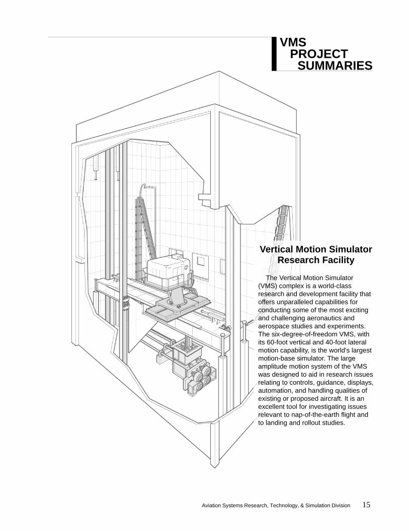
Vertical Motion SimulatorResearch Facility
The Vertical Motion Simulator(VMS) complex is a world-classresearch and development facility thatoffers unparalleled capabilities forconducting some of the most excitingand challenging aeronautics andaerospace studies and experiments.The six-degree-of-freedom VMS, withits 60-foot vertical and 40-foot lateralmotion capability, is the world's largestmotion-base simulator. The largeamplitude motion system of the VMSwas designed to aid in research issuesrelating to controls, guidance, displays,automation, and handling qualities ofexisting or proposed aircraft. It is anexcellent tool for investigating issuesrelevant to nap-of-the-earth flight andto landing and rollout studies.
VMS PROJECT
SUMMARIES

16 Aviation Systems Research, Technology, & Simulation Division
Boeing B1, A1, A2Henry Beaufrere, Kurt Grevstad, Paul McDowell, The Boeing Company;
William Chung, James Franklin, NASA ARC; Leslie Ringo, Chuck Perry, Emily Lewis,Girish Chachad, Alberto Sanchez-Chew, Ron Gerdes, Logicon Syscon/Syre
The U.S. Navy variant of the JSF is shown performing acarrier landing.
SummaryDuring the Fiscal Year 1998, three separate VMS
simulations were conducted to support the designand development of the Boeing X-32 Joint StrikeFighter and to advance NASA-sponsored research inguidance systems, display technology, and shorttakeoff/vertical landing controls.Introduction
NASA Ames Research Center plays a key role insupport of the U.S. Government’s Joint Strike Fighter(JSF) Program, which will field an affordable, highlycommon family of next-generation, multi-role strikefighters for the Navy (USN), Air Force (USAF),Marine Corps (USMC), United Kingdom Royal Navy,and other U.S. allies. The military services have
stated their needs for the JSF as follows:• USN - first-day-of-war survivable strike fighteraircraft to replace the A-6 and F-14 and to comple-ment the F/A-18E/F• USAF - multi-role aircraft (primary-air-to-ground) toreplace the F-16 and A-10 and to complement the F-22• USMC - short takeoff/vertical landing (STOVL)aircraft to replace the AV-8B and F/A-18A/C/D• Royal Navy - STOVL aircraft to replace the SeaHarrier
The Boeing Company is one of two manufacturersselected to build and fly a pair of JSF conceptdemonstrator aircraft. Real-time, piloted flight simula-tion is an important step in Boeing’s approach to JSFdesign and development. The VMS, with its large
motion travel, was used to complement Boeing’s in-house, ground-based simulator prior to in-flightsimulation and flight testing. The objectives of thethree simulations included control law refinement,flying qualities evaluation, pilot-induced oscillationinvestigation, and advanced control and displaydesign exploration.Simulations
Test pilots from Boeing, USN, USAF, USMC, RoyalNavy, Royal Air Force, and NASA participated in theevaluations. Simulations were conducted for a total ofnine weeks on the motion base. In preparation for themotion-base experiments, a total of four weeks offixed-base simulation was conducted to validate thesimulation system response and to finalize flighttasks and scenarios. Validation of the response wascritical because Boeing’s entire aircraft simulationsoftware was directly integrated into the VMS.Results
The primary objectives of the simulations weremet, and the customer obtained considerable infor-mation for design analysis and evaluation. Test pilotswere favorably impressed with the important role thatlarge motion cueing played in evaluating the JSF’sflying qualities and mission capabilities. The competi-tion sensitive nature of this project precludes theinclusion of detailed results in this report.
For SimLab, these simulations were the first tointegrate the complete aircraft model softwareprovided by the customer into the VMS simulationsystem. SimLab also created a visual database of theU.S. Navy’s Patuxent River Test Center containinghighly realistic aircraft carrier and tanker models forthe JSF Program Office to support all JSF ground-based flight simulation activities. VMS personnel alsodeveloped head-up display graphics and lateralguidance logic for the simulation and incorporatedspecialized hardware for Boeing.
For information regarding the Boeing JSF pro-gram, please refer to http://www.boeing.com. For theU.S. JSF Program Office, see http://www.jast.mil.
Investigative TeamThe Boeing CompanyNASA Ames Research CenterU.S. NavyU.S. Air ForceU.S. Marine CorpsU.K. Royal NavyU.K. Royal Air Force
Aviation Systems Research, Technology, & Simulation Division 17
Simulation Fidelity Requirements 5
SummarySimulation Fidelity Requirements 5 utilized the
large motion capabilities of the VMS to evaluate theeffectiveness of simulator motion cues in predictingpilot-induced oscillation.Introduction
In general, ground-based simulations have notaccurately predicted pilot-induced oscillation (PIO). Aprevious study at Edwards Air Force Base docu-mented PIO susceptibility using the NT-33 variablestability jet. The pitch control systems of the plane’sflight control computer were arranged in 18 configu-rations, ranging in their susceptibility to PIO. Theresults of the Edwards study were used as a baselinefor comparison in Simulation Fidelity Requirements 5(SimFR 5).
The objective of SimFR 5 was to determine theeffectiveness of various motion cueing levels inpredicting PIO.Simulation
A math model of the NT-33, including the 18control system configurations tested in flight, wasdeveloped by NASA personnel. The offset landingsoriginally flown at Edwards were chosen for theirtendency to induce PIO and were simulated inSimFR 5 using an existing visual database ofEdwards.
To study how effectively PIO is predicted withvarious levels of simulation motion cues, the 18configurations were flown in three modes: largemotion, small motion, and fixed-base. Large motionused the normal VMS range, small motion waslimited to the range of a conventional hexapodplatform, and fixed-base simulation involved nomotion at all. For effective pitch cues, the cab was
oriented to allow 40 feet of longitudinal travel. Six testpilots from NASA Ames, Boeing, the FAA, andLogicon Syscon/Syre completed a total of 1720 dataruns.Results
Initial results indicate that large motion bestmatched the in-flight results for handling qualities andPIO ratings. Only with large motion did significantPIO occur, probably due to the pilots’ reactions to thehigh-fidelity vertical acceleration cues. With largemotion, pilots assigned higher confidence factorratings, achieved lower touchdown velocities, andcaused fewer safety pilot trips as compared to theother motion configurations. Results of the studywere presented to the 1998 Atmospheric FlightMechanics Conference of the American Institute ofAeronautics and Astronautics in the paper “Pilot-Induced Oscillation Prediction with Three Levels ofSimulation Motion Displacement.”
Investigative TeamNASA Ames Research CenterLogicon Syscon/SyreThe Boeing CompanyFederal Aviation Administration
William Chung, Jeffery Schroeder, NASA ARC;Soren LaForce, Norman Bengford, Logicon Syscon/Syre; Duc Tran, NASA ARC
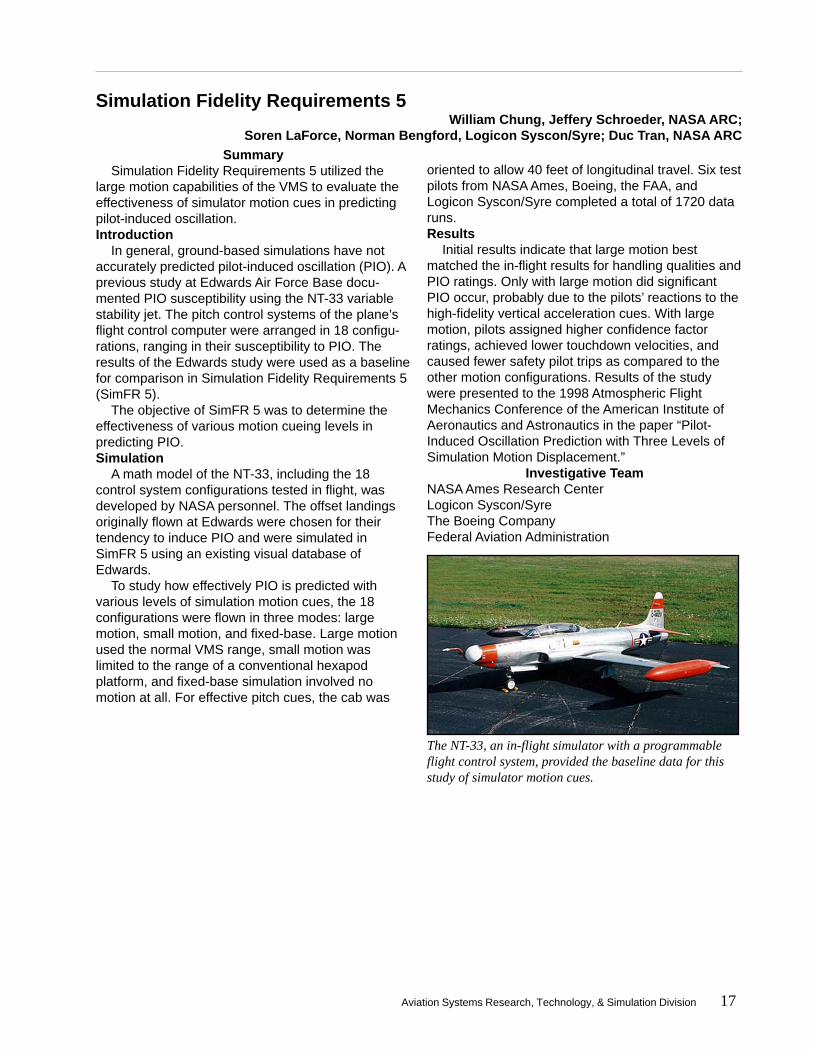
The NT-33, an in-flight simulator with a programmableflight control system, provided the baseline data for thisstudy of simulator motion cues.
18 Aviation Systems Research, Technology, & Simulation Division
Civil Tiltrotor 7William Decker, NASA ARC;
Steve Belsley, Emily Lewis, Philip Tung, Norman Bengford, Logicon Syscon/Syre
SummaryContinuing a series of tiltrotor simulations at the
VMS, Civil Tiltrotor 7 investigated aircraft guidance,terminal flight procedures, and varying environmentalconditions for tiltrotor transports. Flight path vectorguidance with a longitudinal control director wasimplemented, and the effects of tail winds on ap-proach profiles were evaluated.Introduction
Civil Tiltrotor 7 (CTR 7) was the latest in a series ofsimulations to investigate issues that include CTRcertification, terminal area operations, and vertiportdesign. Recent experiments have investigated powerlevel requirements for one-engine-inoperativeoperations and noise abatement procedures forvertiports located in congested areas. Implementingnoise abatement procedures and maneuvering inairport terminal airspace require complex instrumentapproaches. Previous simulations have highlightedthe need for appropriate guidance for these ap-proaches, during which conversion from airplanemode to helicopter mode occurs. In CTR 6, lateralflight path guidance was evaluated.
CTR 7 was designed to examine aircraft guidance,terminal flight procedures, and environmental condi-tions. Specific objectives included the implementationof the flight path vector guidance with a longitudinalcontrol director, the evaluation of tail wind effects onapproach profiles based on ground speed, and theevaluation of a new wind model that includes an
earth boundary layer and directional shear effects.For control design and analysis, CTR 7 documentedaircraft speed, rotor speed, and thrust control re-sponse. Members of the FAA’s Vertiport DesignGuide Working Group were invited to the VMS toobserve design and tiltrotor operation issues.Simulation
The simulation marked the first CTR use of theTCAB. This new cab was designed for the simulationof civil transport aircraft and features two side-by-sideseats, a full range of electronic instruments, and a240° X 60° field of view. Flight procedures for CTR 7were therefore modified to include the duties of asecond, non-flying pilot. For more effective accelera-tion and deceleration motion cueing during the criticalnacelle conversion, the TCAB was oriented to allow40 feet of longitudinal travel. The use of a side-stickcontroller for CTR was introduced in this simulation.Test pilots from the FAA, NASA, and industry partici-pated in the experiment. Experienced in-house pilotsevaluated the side-stick controller and the new windshear model.Results
CTR 7 successfully implemented flight path vectorguidance with a longitudinal control director. Informa-tion was documented for aircraft speed, rotor speed,and thrust control response for control systemanalysis and design. With the introduction of the two-seat TCAB to CTR simulations, a second pilot wasintegrated into the CTR scenario, and duties weredefined for the non-flying pilot. The new wind modeland the effects of tail winds on approach profileswere evaluated. Vertiport design and tiltrotor opera-tion issues were demonstrated to members of theVertiport Design Guide Working Group.
Investigative TeamNASA Ames Research CenterLogicon Syscon/SyreBell HelicoptersThe Boeing CompanySikorsky AircraftFederal Aviation AdministrationU.S. Army
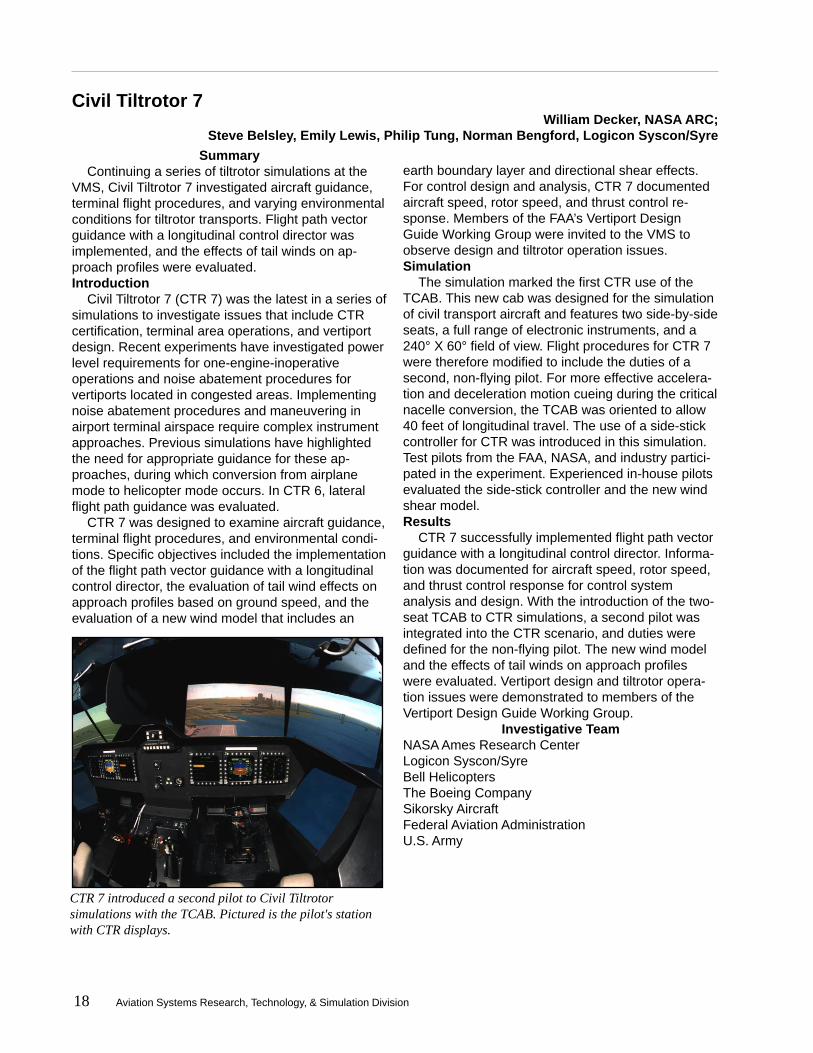
CTR 7 introduced a second pilot to Civil Tiltrotorsimulations with the TCAB. Pictured is the pilot's stationwith CTR displays.
Aviation Systems Research, Technology, & Simulation Division 19
Lockheed MartinMark Tibbs, Lockheed Martin; James Franklin, NASA ARC;
Robert Morrison, Leslie Ringo, Joe Ogwell, Luong Nguyen, Ernie Inn, Logicon Syscon/Syre
SummaryLockheed Martin’s X-35 Joint Strike Fighter model
was simulated to support the design and develop-ment of the X-35 and to advance NASA-sponsoredresearch in guidance systems, display technology,and short takeoff/vertical landing controls.Introduction
NASA Ames Research Center plays a key role insupport of the U.S. Government’s Joint Strike Fighter(JSF) Program, which will field an affordable, highlycommon family of next-generation, multi-role strikefighters for the Navy (USN), Air Force (USAF),Marine Corps (USMC), United Kingdom Royal Navy,and other U.S. allies. Each of the military serviceshas specified unique requirements for its version ofthe JSF. For example, the USAF primarily expects anair-to-ground fighter that will be a significant improve-ment over the F-16. The USN variant will serve as astrike fighter to replace the A-6 and F-14. The USMCversion distinguishes itself with its short takeoff/vertical landing capabilities and will serve as areplacement for the AV/8B and F/A-18A/C/D. TheJSF is expected to enter service in 2008.
The Department of Defense awarded LockheedMartin Corporation one of two JSF contracts. Thecontract calls for two concept demonstrator aircraft,the first of which is scheduled for rollout in 1999. Thissimulation, using the large motion base at the VMS,was conducted by Lockheed Martin to complementtheir in-house simulations as part of the design anddevelopment process. The objective of the experi-ment included control law refinement, flying qualitiesevaluation, and advanced control and display designexploration.Simulation
Two weeks of fixed-base simulation were followedby three weeks of motion-base operations. The fixed-base session was designed to validate the simulationsystem response and to finalize flight tasks andscenarios in preparation for the motion-base experi-ment. The response validation phase was a criticalstep since the computer code for the entire aircraftmodel was generated by Lockheed Martin anddirectly integrated into SimLab’s simulation environ-ment. Pilots and engineers from Lockheed Martin,the U.S. Navy and Marine Corps, U.K. Royal AirForce and Royal Navy, and British Aerospaceparticipated in the evaluations.
ResultsThe primary objectives for the simulations were
met, and significant amounts of evaluation data werecollected. The large motion cueing of the VMSsystem played a critical role in evaluating the flyingqualities and mission capabilities of LockheedMartin’s JSF design.
For SimLab, this simulation marked a continuedsuccess in integrating the entire aircraft modelsoftware provided by a customer into SimLab’s real-time system. This mode of operation allowedLockheed Martin to test several last minute designchanges, which were expediently integrated bySimLab engineers. Due to the competition sensitivenature of the project, detailed results cannot beincluded in this report.
For further information regarding the JSF program,please refer to the Lockheed Martin and JSF Pro-gram Office world wide web pages athttp://www.lmco.com and http://www.jast.mil, respec-tively.
Investigative TeamNASA Ames Research CenterLockheed MartinU.S. Marine CorpsU.K. Royal NavyU.K. Royal Air ForceBritish Aerospace
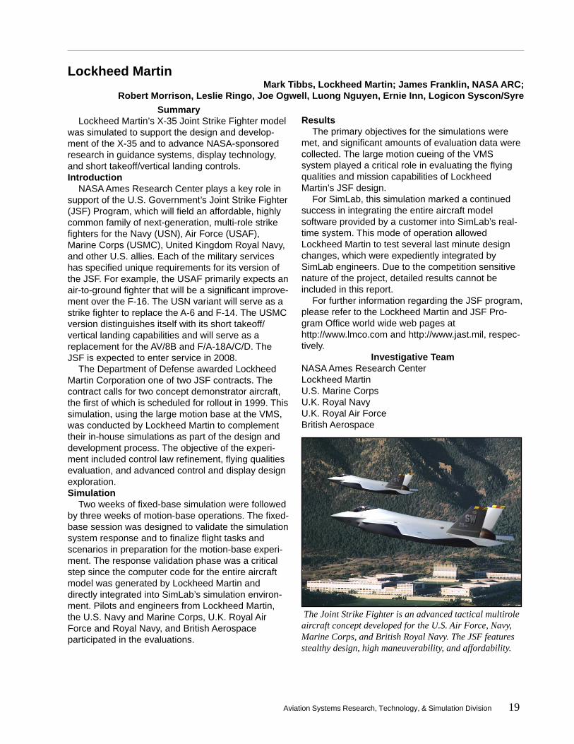
The Joint Strike Fighter is an advanced tactical multiroleaircraft concept developed for the U.S. Air Force, Navy,Marine Corps, and British Royal Navy. The JSF featuresstealthy design, high maneuverability, and affordability.
20 Aviation Systems Research, Technology, & Simulation Division
Space Shuttle Vehicle 1Howard Law, NASA JSC; Kyle Cason, The Boeing Company; Jim Harder, United Space Alliance;
Estela Hernandez, Christopher Sweeney, Logicon Syscon/SyreSummary
The Space Shuttle Orbiter landing and rolloutstudies are performed at the VMS to fine-tune theOrbiter’s landing systems. The primary goal of thissimulation was to study the effects of changing theflow rate of the hydraulic system powered by theAuxiliary Power Unit.Introduction
The Space Shuttle Orbiter has been simulated atSimLab since the late 1970s. The simulation at Ameshas been used to test flight control improvements,safety features, head-up display developments,proposed flight rule modifications, and changes to thebasic simulation model, which has evolved over theyears. The simulation is also used to train astronautswith realistic landing and rollout scenarios beforetheir flight and includes scenarios with systemfailures.Simulation
Simulation objectives were to:• Study the effects and pilot procedures of single anddual Auxiliary Power Unit (APU) failures duringapproach and landing. This was studied primarily due
to a recent SSV mission in which a single APU failureoccurred.• Study the effects of increasing the flow rate of asingle or dual APU hydraulic system from 63 gallonsper minute to 90 gallons per minute per APU. Theproposed increase would be coupled with changes tothe Priority Rate Limiting system.• Continue evaluation of Virtual Laboratory (VLAB).VLAB allowed researchers at Johnson Space Centerto monitor and interact with Shuttle simulations inprogress at the VMS and to record data. (For moreon VLAB, see the Technology Upgrades section page44.)• Train upcoming mission crews and astronautcandidates through a crew familiarization matrix.
For this simulation, the gear model was modifiedto simulate tire deflection, and the capability toimmediately display APU data at the end of each runwas added. A program was written to automaticallytranslate the Space Shuttle Vehicle test matrix intodata files for input into the simulation program. Theprogram eliminated several days of manual entry to aseveral hour process and can be adapted for othersimulations.Results
A total of 1210 runs was completed with 35 pilots.Preliminary results show that for the 63 gallons perminute single or dual APU, landings can be success-fully achieved if the pilot avoids control surfacesaturation by minimizing control inputs. Preliminaryresults also show that the increased flow rate to 90gallons per minute, coupled with changes to thePriority Rate Limiting logic, would reduce the fre-quency and duration of rate saturation.
The crew familiarization phase of the simulationreinforced the importance of the VMS in preparingupcoming crews for the landing and rollout phase ofthe mission and for possible failures during thatphase.
Investigative TeamNASA Johnson Space CenterNASA Ames Research CenterThe Boeing CompanyUnited Space Alliance
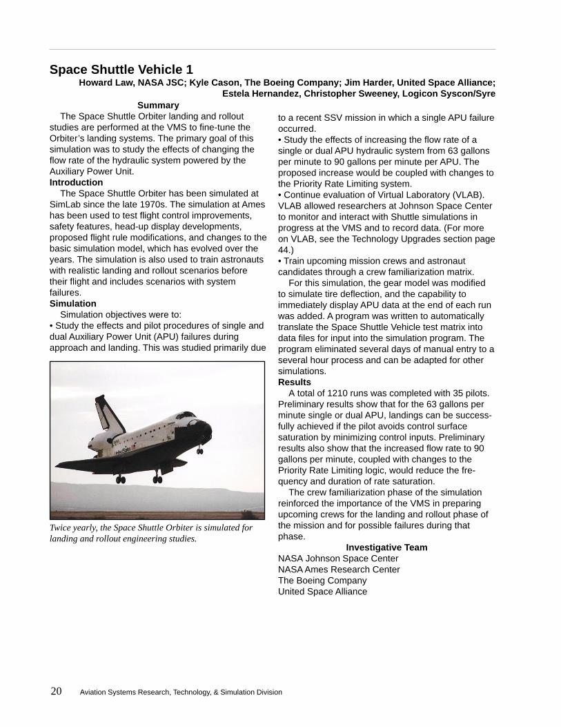
Twice yearly, the Space Shuttle Orbiter is simulated forlanding and rollout engineering studies.

Aviation Systems Research, Technology, & Simulation Division 21
Helicopter Maneuver Envelope Enhancement 5Matthew Whalley, Jay Shively, U.S. Army AFDD;
Chuck Perry, Alberto Sanchez-Chew, Logicon Syscon/Syre
SummaryThe latest in a series of VMS simulations, this
experiment continued research into predictinghelicopter flight envelope limits and communicatingthose limits to the pilot. In this simulation, tactilecueing of blade stall and mast bending moment wereimplemented using polynomial neural networks.Introduction
Helicopters typically have complicated flightenvelope limits that are difficult to predict during flightand that are poorly displayed to the pilot. To date,only indirect and simplified cueing of limits has beenviable. The introduction of fly-by-wire (all-electronic)control systems has further decreased pilot aware-ness of control actuator authority limits and haseliminated flight control force feel. Consequently,conservative restrictions to the maneuvering enve-lope are often imposed.
The purpose of the Helicopter Maneuver EnvelopeEnhancement (HelMEE) simulation series is toincrease pilot awareness of envelope limits. HelMEE4 implemented a polynomial neural network (PNN) topredict transmission torque limits and a control forcefeel system to provide tactile cueing of those limits tothe pilot. Force cues were delivered through thecollective and indicated when the transmission torqueoutput relative to a maximum continuous limit wasreached.
HelMEE 5 continued this investigation of cueingusing PNNs. The goals of the simulation were toimprove the PNN used in HelMEE 4, to implementcollective cueing for blade stall, and to implementcyclic cueing for mast bending moment.Simulation
HelMEE 5 simulated the UH-60 Black Hawk with astandard flight control system. Considerable effortwas devoted to improving the PNN performance.Additional test parameters, such as high altitudes,high ambient temperatures, and high aircraft grossweight were simulated to increase torque and mastbending moment, requiring the helicopter to operatenear its limits more frequently. The collective andcyclic cues were exercised both separately andtogether.
Collective cueing for both torque and blade stallwas achieved by implementing a softstop and a highgradient force. The softstop allowed the pilot to pullthrough the cue if desired. Because mast bendingmoment is more dependent on the velocity of stickinput than on the stick position, cyclic cueing wasintroduced as a large increase in the damping force.In all cases, stick shaking and head-up displays wereused as additional limiting cues.Results
The results of HelMEE 5 indicate improved pilottask performance and reduced pilot workload.Effective cueing reduced or eliminated the need tovisually monitor the torque gauge during a task. Asignificant improvement was found in the handlingqualities ratings provided by the test pilots. In all, 872runs, including 387 data runs, were flown by pilotsfrom NASA, Logicon Syscon/Syre, FAA, BoeingHelicopters, Bell Helicopters, Columbia Helicopters,and three U.S. Army organizations.
Investigative TeamU.S. ArmyNASA Ames Research CenterLogicon Syscon/SyreBoeing HelicoptersBell HelicoptersColumbia HelicoptersFederal Aviation AdministrationBarron Associates
HelMEE 5 simulated the UH-60 Black Hawk with astandard flight control system.

22 Aviation Systems Research, Technology, & Simulation Division
Slung Load 5Chris Blanken, U.S. Army AFDD; Robert Heffley, R. Heffley Engineering;
Roger Hoh, Hoh Aeronautics; Robert Morrison, Luong Nguyen, Logicon Syscon/Syre
SummaryThe CH-47D Chinook helicopter was simulated to
improve handling qualities criteria for cargo helicop-ters in slung load operations and to refine techniquesfor measuring those criteria.Introduction
The Slung Load 5 simulation experiment, the fifthin a series of VMS simulations conducted by the U.S.Army Aeroflightdynamics Directorate, was performedto obtain data for specifying handling qualities forcargo helicopters in slung load operations. Thisresearch is part of the Army’s Improved CargoHelicopter program, aimed at upgrading the BoeingCH-47D Chinook heavy-cargo helicopters to extendtheir lives beyond the year 2020. Without the pro-gram, the first Chinooks would reach the end of theirservice life in 2002. A secondary aim of the simula-tion was to correct deficiencies in the CH-47Ds thatadversely affected their mission operations duringDesert Storm.
Data from prior Slung Load simulations raisedseveral questions and issues. While many usefulhandling qualities criteria have been defined forcargo helicopter operations with slung loads, a fewinconsistencies in the data indicate that the under-standing of how to apply the proposed standards isincomplete. Other lingering questions concernedmeasurement techniques for handling qualities
characteristics, particularly for frequency responsedefinition.
The purpose of the Slung Load 5 experiment wasto resolve these questions and issues by reviewingconfigurations that are inconsistent with currentlyproposed criteria, studying the measurement ofhandling qualities features in more depth, andexploring previously unexamined frequency responsefeatures.
Specifically, the objectives included: studying thevalidity of gain margin handling qualities criteria forslung load tasks (mainly precision hover), providing abetter theoretical basis for bandwidth criteria bydefining the load-off rating trend for precision hoverwith the load-on performance time, gathering data onhow ratings are influenced by the large difference inmoments of inertia in the roll and pitch axes, andcontinuing the study of frequency response measure-ment methods using pilot-produced inputs.Simulation
The CH-47D was simulated with various configura-tions: with and without a slung load of 16,000pounds, with single- and dual-point suspended loads,with loads using various sling lengths and distancesfrom the hook to the aircraft center of gravity, andwith different control system gains. With the slungload, the dynamics of the aircraft are affected notonly by the basic aircraft response but also by thecoupled response from the external load. Pilots fromNASA, Boeing, and Logicon/Syre flew a total of 885data runs.Results
Slung Load 5 developed important handlingqualities relationships for a large variety of controlsystems and sling configurations. For internal loads,the bandwidth parameter was determined to be agood control response discriminator but was found tobe insufficient by itself for characterizing the controlresponse with external loads. Finally, the largemotion provided by the VMS proved essential inproviding the pilot with realistic cues of the motioncaused by the swinging of the external load.
Investigative TeamU.S. ArmyNASA Ames Research CenterThe Boeing CompanyLogicon Syscon/SyreR. Heffley EngineeringHoh Aeronautics
Pictured above is a view of the simulator cockpitconfigured for the Slung Load simulation.

Aviation Systems Research, Technology, & Simulation Division 23
Simulation Fidelity Requirements 6
SummarySimulation Fidelity Requirements 6 was a joint
research program with the University of California atDavis that used the large vertical travel of the VerticalMotion Simulator to gather data for the developmentand validation of a pilot model.Introduction
Visual and motion cues play a critical part inpiloted simulation and significantly affect a pilot’sperception of vehicle response, which in turn affectsa pilot’s performance of defined tasks. Exactly howthese cues affect the pilot and to what degree are yetto be determined in a validated scientific study. Eachcue has numerous characteristics or attributes; forexample, scene content, resolution, and field of view
are just some of the characteristics of the visual cue.These attributes directly affect pilot perception andinteractively produce significant changes in pilotresponse.
The objective of Simulation Fidelity Requirements6 (SimFR 6) was to develop and validate a pilotmodel in a single degree of freedom to characterizehow the pilot processes and responds to major visualand motion cueing attributes. Development of avalidated pilot model will provide important objectiveinsight and will advance the development of stan-dards and criteria for cueing fidelity in ground-basedflight simulation.Simulation
To begin this line of inquiry, SimFR 6 limited thescope of the study to the vertical motion axis and toselect characteristics. Three cueing attributes werechosen: visual resolution, field of view, and magni-tude of motion. The experiment combined these cuesin 42 configurations. A one-to-one motion cueingconfiguration, in which the simulator exactly dupli-cated aircraft response, was developed as a baselinecase. A precision hover task with a 40-foot bob-upand bob-down was flown. Particular care was takento ensure the synchronous delivery of motion andvisual cues.Results
SimFR 6 was successful in the collection of dataregarding the effects of various cueing configura-tions. A total of 1068 data runs were recorded. Thedata will be used to develop and validate a pilotcueing perception model in the vertical axis. Aftervalidation, the methodology of this investigation willbe expanded to multiple degrees of freedom, contrib-uting to the development of standards and criteriathat will help determine minimum requirements forcueing in motion-base simulation.
Investigative TeamNASA Ames Research CenterLogicon Syscon/SyreUC DavisU.S. Army
Simulation Fidelity Requirements 6 was a joint researchprogram with the University of California at Davis thatused the large vertical travel of the Vertical MotionSimulator to gather data for the development andvalidation of a pilot model.
William Chung, Logicon Syscon/Syre; Jeffery Schroeder,Duc Tran, NASA ARC; Ron Hess, UC Davis; Soren LaForce, Logicon Syscon/Syre
24 Aviation Systems Research, Technology, & Simulation Division
High Speed Civil Transport Design & IntegrationThea Feyereisen, Bill Rogers, Honeywell; Gordon Hardy, Logicon Syscon/Syre;
Christopher Sweeney, Joseph Ogwell, Robert Morrison, Phil Tung, Logicon Syscon/Syre;Duc Tran, NASA ARC
SummaryThis study, conducted by the Design and Integra-
tion team of the High Speed Research Program,examined two areas of flight deck management:Crew Interaction with Automation and Crew/AutoflightIntegration.Introduction
The High Speed Research (HSR) Program is acollaborative effort between NASA and the U.S.aeronautics industry. The goal of this effort is todevelop the high-leverage technologies necessary foran environmentally acceptable, economically viablehigh speed civil transport (HSCT) and to provideintercontinental service at Mach 2.4 for three hundredpassengers beginning in the year 2005.
In support of this goal, the HSR Program’s Designand Integration team has developed various con-
cepts for flight deck management. HSR Programmilestones called for final piloted evaluation of theconcepts in a simulator.Simulation
High Speed Civil Transport Design and Integration(HSCT D&I) evaluated flight deck design concepts interms of pilot performance, workload, and situationawareness in managing and interacting with severaldifferent automated systems unique to the HSCT.The systems were divided into two areas of study.
1. Crew Interaction with Automation - High-liftdevices on the HSCT have dynamic schedules rather
than the discrete static schedules typical on subsonicaircraft; hence, a discrete setting flap lever would beinadequate, and control of the schedules will likely behighly automated under normal circumstances. Thepilots need to stay involved in and informed abouthigh-lift device authority and status in order to detectanomalies and revert to a less automated level ofcontrol if necessary. The automated flap control isanticipated to make manual control of thrust moredifficult. Evaluation of pilot performance while inter-acting with the high-lift device automation andmanual throttles in normal and failure modes weregoals of the Crew Interaction with Automation study.
2. Crew/Autoflight Integration - The HSCT willhave different control laws than normal aircraft,changing the requirements and interface issues foraircraft mode control and annunciation. An autoflightmode structure must be developed that is under-standable and consistent with the flight control lawparadigms. The effect of this structure on envelopeprotection, mode awareness, and pilot proceduresmust be addressed. Pilot performance and aware-ness while interacting with and monitoring theautoflight system were the key goals of the Crew/Autoflight Integration portion of the experiment.
The bare airframe model was updated to the latestHSCT design release for HSCT D&I. The control lawswere implemented using Matlab Simulink designtools. Matlab’s autocoding feature was used toconvert the block diagrams into C language routines,which were integrated with the rest of the FORTRANcode. Algorithms for a Mode Control Panel andvertical guidance logic were also added to the model.Results
For HSCT D&I, 105 data runs of three differenttasks were completed for the two areas of study.Preliminary results indicate that pilot awareness ofthe unique problems of an HSCT aircraft is criticaland that advanced flight deck management conceptswill need further development.
Investigative TeamThe Boeing CompanyHoneywellNASA Ames Research CenterNASA Langley Research CenterLogicon Syscon/Syre
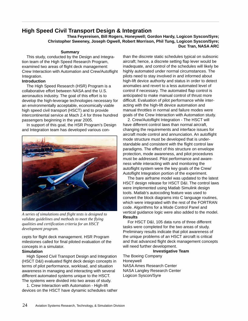
A series of simulations and flight tests is designed tovalidate guidelines and methods to meet the flyingqualities and certification criteria for an HSCTdevelopment program.

Aviation Systems Research, Technology, & Simulation Division 25
High Speed Civil Transport A7Jim Ray, Todd Williams, The Boeing Company; Gordon Hardy, Logicon Syscon/Syre;
Christopher Sweeney, Joseph Ogwell, Robert Morrison, Phil Tung, Logicon Syscon/SyreSummary
The High Speed Research Program conducted afour-part experiment in the VMS to evaluate theperformance of the flight control system and to verifyand validate the bending mode response of the highspeed civil transport.Introduction
To support the development of a high speed civiltransport (HSCT), the High Speed Research (HSR)Program’s Guidance and Flight Controls team isconducting a series of simulations and flight testsdesigned to validate guidelines and methods to meetflying qualities and certification criteria. (For more onthe HSR Program, see the HSCT D&I Introduction onpage 24.)Simulation
Part 1, the main thrust of High Speed Civil Trans-port Ames 7 (HSCT A7), involved gathering handlingquality ratings (HQRs) for the entire flight envelope todetermine if the control system designs have mettargeted HQRs. Forty-one flight cards were used togather data on takeoff, approach and landing, cruise,envelope protection, and failure tasks. Each card hada target HQR, and a database of pilot opinion andperformance was generated to evaluate the vehicleand control laws against these targets.
Part 2 of the study attempted to discover appropri-ate levels of roll control sensitivity criteria (roll accel-eration per pound force of lateral stick) in order todevelop a criterion for the flying qualities level 1-2boundary of an HSCT type aircraft in both subsonicand supersonic flight regimes. For Part 3, a modifiedHSCT configuration was evaluated for improvementsin the approach and landing phase of flight. For Part4, an initial attempt was made to evaluate the effectsof the bending modes, or the Dynamic Aero ServoElastic (DASE) response of the aircraft, on the pilotand control laws.
Dynamic Aero Servo Elastics (DASE) is thephenomenon which results from the interactionbetween aerodynamic forces, structural (elastic)forces, and inertial forces. DASE excites the naturalbending modes of the aircraft, causing the aircraft tovibrate. If left uncontrolled, these vibrations can affect
the comfort and safety of passengers, as well as thestructural integrity of the aircraft. Therefore, it iscritical that the DASE effects be investigated for thisaircraft, which has a unique shape and will operateover a wide range of speeds.Simulation Results
Preliminary results for the simulation indicate thatthe Guidance and Flight Control design element isexceeding desired HQR targets for most of the flightenvelope; only a few areas of the envelope needrefinement. A large quantity of data was gathered tohelp designers determine the appropriate roll controlsensitivity. The modified HSCT configuration per-formed well in the approach and landing task, butmight be unnecessary since Level 1 HQRs wereachieved with the baseline configuration. The evalua-tion of the bending mode effects proved to be abeneficial first look, which revealed the relevantissues that warrant further investigation.
Investigative TeamThe Boeing CompanyHoneywellNASA Ames Research CenterNASA Langley Research CenterLogicon Syscon/Syre
The goal is to develop the high-leverage technologiesnecessary for an environmentally acceptable,economically viable High Speed Civil Transport.

26 Aviation Systems Research, Technology, & Simulation Division
High Speed Civil Transport A7B
SummaryThis experiment was conducted by the High
Speed Research Program to evaluate the modelingof the Dynamic Aero Servo Elastic effects and theaircraft response during approach and landing.Introduction
To support the development of a high speed civiltransport (HSCT), the High Speed Research (HSR)Program’s Guidance and Flight Controls team isconducting a series of simulations and flight testsdesigned to validate guidelines and methods to meetflying qualities and certification criteria. (For more onthe HSR Program, see the HSCT D&I Introduction.)
During the earlier High Speed Civil TransportAmes 7 (HSCT A7) simulation, the Dynamic AeroServo Elastic (DASE) model was added to thenominal HSCT aircraft in the last week of the simula-tion. (For more on DASE, see HSCT A7 on page 25.)Many issues were identified for further investigationin a follow-on experiment. In HSCT A7B, the aircraft’stwenty bending modes were predicted to make thepiloting task a difficult one without any active struc-tural mode control (SMC). This study evaluated theaccuracy of the DASE modeling; the effectiveness ofthe SMC; the ability of the VMS motion system toaccurately reproduce the pilot station accelerations;and the effects of inceptors, center stick versus
wheel/column, on the tendency of the pilot to bio-couple with the aircraft.Simulation
In HSCT A7B, an alternate method of implement-ing the DASE model was investigated. In order to runthe entire simulation at 100 Hz (HSCT A7 sub-framedthe DASE model at 400 Hz), only the first sevenbending modes (up to 20 radians per second) wereused.
Two different methods of control law implementa-tion were tested. The continuous model of the controllaw contained a cascade of filters, to which theMatlab autocoder added a cycle of delay for eachfilter. A discretized version of the control law tuned for100 Hz was developed to remove this known pro-gramming delay. However, the lateral-directionalportion of this control law implementation was foundto be unstable; therefore, most of the data for thesimulation was taken with the continuous control lawimplementation.Simulation Results
Closed loop (with the control laws) piloted runswere made with and without SMC and with the centerstick and wheel/column by three pilots. All of thepilots agreed that the DASE aircraft with SMC off wasa Level 3 vehicle. Two of the pilots had some degreeof bio-coupling with the center stick, while the onlypilot who flew with the wheel/column did not experi-ence such problems. The SMC improved the vehiclehandling qualities ratings to Level 1/Level 2. Furtherinvestigation is needed with the VMS motion systemtuned to provide the highest possible motion fidelityto simulate the high-frequency effects of the DASEcharacteristics.
Investigative TeamThe Boeing CompanyNASA Ames Research CenterNASA Langley Research CenterLogicon Syscon/Syre
Dennis Henderson, Payam Rowhani, The Boeing Company; Gordon Hardy, Logicon Syscon/Syre;Christopher Sweeney, Joseph Ogwell, Phil Tung, Logicon Syscon/Syre
In High Speed Civil Transport A7B, an alternate method ofimplementing the Dynamic Aero Servo Elastic model wasinvestigated.
Aviation Systems Research, Technology, & Simulation Division 27
Partial Authority Flight Control AugmentationMatthew Whalley, U.S. Army AFDD; Jeremy Howitt, U.K. DERA;
Chuck Perry, Emily Lewis, Logicon Syscon/Syre
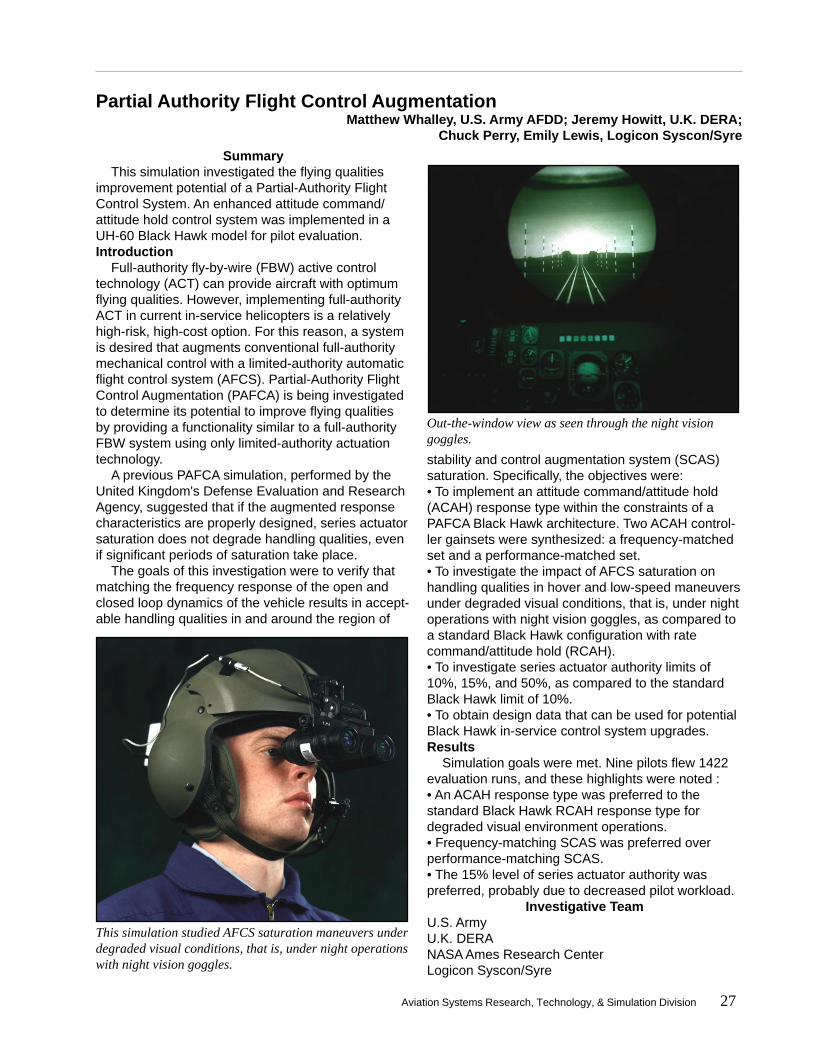
Out-the-window view as seen through the night visiongoggles.
This simulation studied AFCS saturation maneuvers underdegraded visual conditions, that is, under night operationswith night vision goggles.
SummaryThis simulation investigated the flying qualities
improvement potential of a Partial-Authority FlightControl System. An enhanced attitude command/attitude hold control system was implemented in aUH-60 Black Hawk model for pilot evaluation.Introduction
Full-authority fly-by-wire (FBW) active controltechnology (ACT) can provide aircraft with optimumflying qualities. However, implementing full-authorityACT in current in-service helicopters is a relativelyhigh-risk, high-cost option. For this reason, a systemis desired that augments conventional full-authoritymechanical control with a limited-authority automaticflight control system (AFCS). Partial-Authority FlightControl Augmentation (PAFCA) is being investigatedto determine its potential to improve flying qualitiesby providing a functionality similar to a full-authorityFBW system using only limited-authority actuationtechnology.
A previous PAFCA simulation, performed by theUnited Kingdom's Defense Evaluation and ResearchAgency, suggested that if the augmented responsecharacteristics are properly designed, series actuatorsaturation does not degrade handling qualities, evenif significant periods of saturation take place.
The goals of this investigation were to verify thatmatching the frequency response of the open andclosed loop dynamics of the vehicle results in accept-able handling qualities in and around the region of
stability and control augmentation system (SCAS)saturation. Specifically, the objectives were:• To implement an attitude command/attitude hold(ACAH) response type within the constraints of aPAFCA Black Hawk architecture. Two ACAH control-ler gainsets were synthesized: a frequency-matchedset and a performance-matched set.• To investigate the impact of AFCS saturation onhandling qualities in hover and low-speed maneuversunder degraded visual conditions, that is, under nightoperations with night vision goggles, as compared toa standard Black Hawk configuration with ratecommand/attitude hold (RCAH).• To investigate series actuator authority limits of10%, 15%, and 50%, as compared to the standardBlack Hawk limit of 10%.• To obtain design data that can be used for potentialBlack Hawk in-service control system upgrades.Results
Simulation goals were met. Nine pilots flew 1422evaluation runs, and these highlights were noted :• An ACAH response type was preferred to thestandard Black Hawk RCAH response type fordegraded visual environment operations.• Frequency-matching SCAS was preferred overperformance-matching SCAS.• The 15% level of series actuator authority waspreferred, probably due to decreased pilot workload.
Investigative TeamU.S. ArmyU.K. DERANASA Ames Research CenterLogicon Syscon/Syre
28 Aviation Systems Research, Technology, & Simulation Division
Space Shuttle Vehicle 2Howard Law, NASA JSC;
Estela Hernandez, Leslie Ringo, Christopher Sweeney, Logicon Syscon/Syre
SummarySimulations of the Space Shuttle Orbiter are
generally performed at the VMS to conduct landingand rollout engineering studies and to provide crewtraining. This simulation was devoted entirely totraining crews of upcoming missions and astronautcandidates. The simulation also continued theevaluation of Virtual Laboratory as a remote-accesssimulation tool.Introduction
The Space Shuttle Orbiter has been simulated atthe VMS since the late 1970s. The simulation modelhas evolved over the years and is updated to reflectmodifications to the Shuttle. With its superior motioncueing, the VMS provides excellent training opportu-nities for Shuttle crews.
Virtual Laboratory (VLAB), a virtual reality environ-ment that enables researchers at remote sites tomonitor and interact with experiments at the VMS,was deployed to Johnson Space Center (JSC) forthis simulation. (For more on VLAB, see the Technol-ogy Upgrades section on page 44.)Simulation
Training procedures consisted of each pilot landingthe Space Shuttle Orbiter with various configurations,initial conditions, and failure modes, based on casesdefined in the crew-familiarization matrix. Simulationvariables included wind direction and speed, chutedeployment speed, visibility (day or night, clear orcloudy), and location and type of runway (concrete orlakebed). U.S. runways that were simulated includedKennedy Space Center (KSC) 15, KSC 33, Edwards15, Edwards 22, Edwards 23, Northrop White Sandslakebed, Palmdale, and Vandenberg. Transatlanticlanding sites were located in Africa (Banjul, BenGuerir and Dakar) and Spain (Moron and Zaragoza).Periodically, engineers introduced failures to the tires,to a single Auxiliary Power Unit, to the MicrowaveLanding System, and to beep trim.
In August 1998, two VMS simulation engineersobserved the training of Shuttle crews aboard theShuttle Training Aircraft, an in-flight simulator. Thisvaluable firsthand experience exposed the engineersto actual cockpit hardware and to crew trainingprocedures during landings at Northrop runways atWhite Sands, New Mexico. The orientation flightsalso helped to identify areas for possible improve-
ments to VMS simulations.Results
Thirty-five pilots flew over 682 data runs to accom-plish the crew familiarization objective. Participatingwere crews from several upcoming missions, includ-ing STS-88, 92, 93, 95, 96, 97 and 98. Astronautcandidates also took part in the training. In addition,former astronauts from the Shuttle Program Office,including John Young, participated. VLAB provedsuccessful in allowing researchers at JSC to interactwith the simulations as they occurred. This simulationreinforced the importance of the VMS in preparingupcoming crews for the landing and rollout phase ofthe mission and for possible failures during thatphase.
Investigative TeamNASA Johnson Space CenterNASA Ames Research CenterThe Boeing CompanyUnited Space Alliance
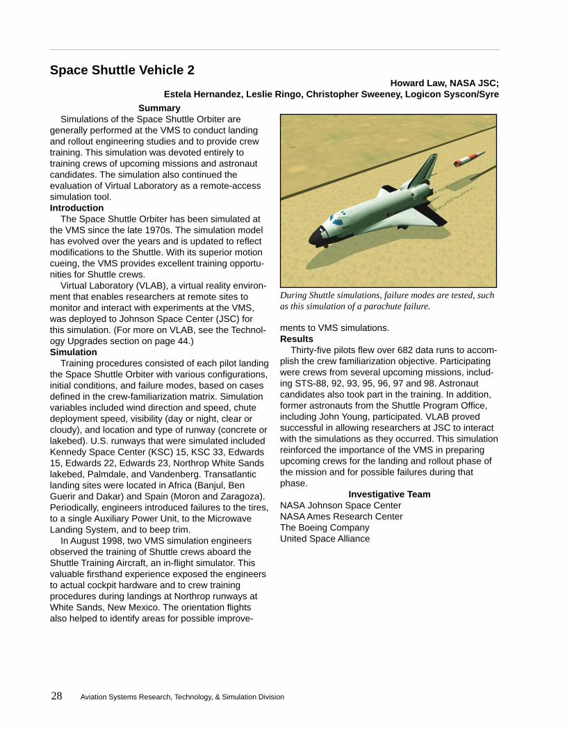
During Shuttle simulations, failure modes are tested, suchas this simulation of a parachute failure.

Aviation Systems Research, Technology, & Simulation Division 29

30 Aviation Systems Research, Technology, & Simulation Division

Aviation Systems Research, Technology, & Simulation Division 31
Crew-Vehicle SystemsResearch Facility
The Crew-Vehicle Systems Research Facility, aunique national research resource, was designed for the
study of human factors in aviation safety. The facility isused to analyze performance characteristics of flight crews;
formulate principles and design criteria for future aviation environ-ments; evaluate new and contemporary air traffic control procedures; and develop new training and simulationtechniques required by the continued technical evolution of flight systems.
Studies have shown that human error plays a part in 60 to 80 percent of all aviation accidents. The Crew-Vehicle Systems Research Facility allows scientists to study how errors are made, as well as the effects ofautomation, advanced instrumentation, and other factors, such as fatigue, on human performance in aircraft.The facility includes two flight simulators - a Boeing 747-400 and an Advanced Concepts Flight Simulator aswell as a simulated Air Traffic Control System. Both flight simulators are capable of full-mission simulation.
CVSRF PROJECT
SUMMARIES
32 Aviation Systems Research, Technology, & Simulation Division
Decision Making
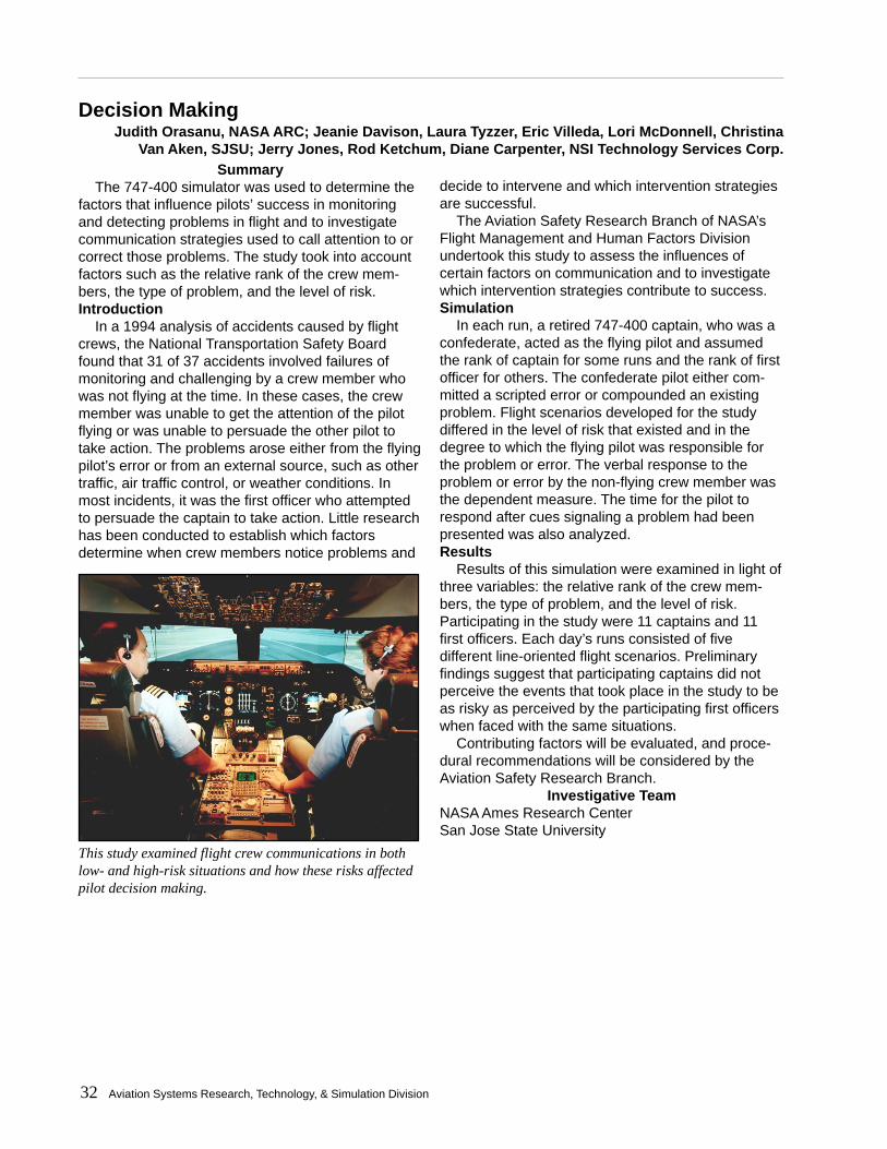
This study examined flight crew communications in bothlow- and high-risk situations and how these risks affectedpilot decision making.
Judith Orasanu, NASA ARC; Jeanie Davison, Laura Tyzzer, Eric Villeda, Lori McDonnell, ChristinaVan Aken, SJSU; Jerry Jones, Rod Ketchum, Diane Carpenter, NSI Technology Services Corp.
SummaryThe 747-400 simulator was used to determine the
factors that influence pilots’ success in monitoringand detecting problems in flight and to investigatecommunication strategies used to call attention to orcorrect those problems. The study took into accountfactors such as the relative rank of the crew mem-bers, the type of problem, and the level of risk.Introduction
In a 1994 analysis of accidents caused by flightcrews, the National Transportation Safety Boardfound that 31 of 37 accidents involved failures ofmonitoring and challenging by a crew member whowas not flying at the time. In these cases, the crewmember was unable to get the attention of the pilotflying or was unable to persuade the other pilot totake action. The problems arose either from the flyingpilot’s error or from an external source, such as othertraffic, air traffic control, or weather conditions. Inmost incidents, it was the first officer who attemptedto persuade the captain to take action. Little researchhas been conducted to establish which factorsdetermine when crew members notice problems and
decide to intervene and which intervention strategiesare successful.
The Aviation Safety Research Branch of NASA’sFlight Management and Human Factors Divisionundertook this study to assess the influences ofcertain factors on communication and to investigatewhich intervention strategies contribute to success.Simulation
In each run, a retired 747-400 captain, who was aconfederate, acted as the flying pilot and assumedthe rank of captain for some runs and the rank of firstofficer for others. The confederate pilot either com-mitted a scripted error or compounded an existingproblem. Flight scenarios developed for the studydiffered in the level of risk that existed and in thedegree to which the flying pilot was responsible forthe problem or error. The verbal response to theproblem or error by the non-flying crew member wasthe dependent measure. The time for the pilot torespond after cues signaling a problem had beenpresented was also analyzed.Results
Results of this simulation were examined in light ofthree variables: the relative rank of the crew mem-bers, the type of problem, and the level of risk.Participating in the study were 11 captains and 11first officers. Each day’s runs consisted of fivedifferent line-oriented flight scenarios. Preliminaryfindings suggest that participating captains did notperceive the events that took place in the study to beas risky as perceived by the participating first officerswhen faced with the same situations.
Contributing factors will be evaluated, and proce-dural recommendations will be considered by theAviation Safety Research Branch.
Investigative TeamNASA Ames Research CenterSan Jose State University

Aviation Systems Research, Technology, & Simulation Division 33
Propulsion Controlled Aircraft 3
VERT SPD
TRACKVERTICALSPEED
DN
UP
FlightControl
Computer
Flight Path & Track
Command
-1000
PilotInputs
Flight Path Angle
Bank Angle/Track
Right Throttle Command
Left Throttle Command
HDG230
Propulsion Controlled Aircraft 3 examined a low-cost, fly-by-throttle control system as a backup system for four-engine aircraft.
Joseph Totah, NASA ARC; John Bull, CAELUM Research Corp.;Diane Carpenter, Jerry Jones, NSI Technology Services Corp.
SummaryThe 747-400 simulator was used to examine a
low-cost, fly-by-throttle control system as a backupfor use in the event of an emergency or a malfunctionof an airplane’s primary flight control system.Introduction
The failure of primary flight control systems hasresulted in numerous accidents. Most notably, UnitedAirlines Flight 232, a DC-10, crash landed at SiouxCity, Iowa on July 19, 1989. The flight crew savedmany lives by skillfully steering using only thethrottles. Following the accident, the National Trans-portation Safety Board informed NASA of the need to“encourage research and development of backupflight control systems for newly certified wide-bodyairplanes that utilize an alternate source of motivepower separate from that source used for the con-ventional control system.”
Propulsion Controlled Aircraft 3 (PCA 3) examineda low-cost, fly-by-throttle control system as a backupsystem for four-engine aircraft. The original controllaws for PCA were developed by NASA Dryden FlightResearch Center. Simulations with the AdvancedConcepts Flight Simulator at CVSRF have investi-gated PCA in a two-engine aircraft, and Dryden hastested PCA with three engines using the MD-11. Anearlier study in the 747-400 simulator applied PCA toa four-engine aircraft for the first time. In conjunctionwith Dryden, the Computational Sciences Division atNASA ARC conducted this simulation to determine ifa simpler, less costly system for four-engine aircraftcould be safely used.Simulation
The PCA control laws essentially allowed subjectpilots to fly the 747-400 Simulator using only thethrottles for pitch and roll commands, without the useof the airplane’s primary flight control systems. Pitchand roll commands were input via the vertical speedcommand and heading select knob on the airplane’sMode Control Panel whenever PCA mode wasselected. Using the throttle commands, thrust inputswere translated through software into equivalent pitchand roll inputs, allowing pilots to maintain control of
the malfunctioning aircraft. In the earlier PCA studies,symmetric and asymmetric engine pressure ratiocommands from the flight computer were used todirect the 747’s electronic engine controls, whichbypassed the throttle servos. This study, however,utilized symmetrical pitch commands instead, whichdrove the aircraft throttle servos, while the pilotsmoved the throttles asymmetrically to control theaircraft roll angle.Results
Test subjects came from NASA Dryden, NASALangley Research Center, the U.S. Navy, andcommercial airlines. They included Captain AlHaynes, pilot of the DC-10 that crash landed in SiouxCity. Results indicated that, although PCA Ultralite isan improvement over manual throttle control alone, itdoes not provide landings as consistent or as safe asthe PCA baseline tested previously.
Investigative TeamNASA Ames Research CenterCAELUM Research Corporation
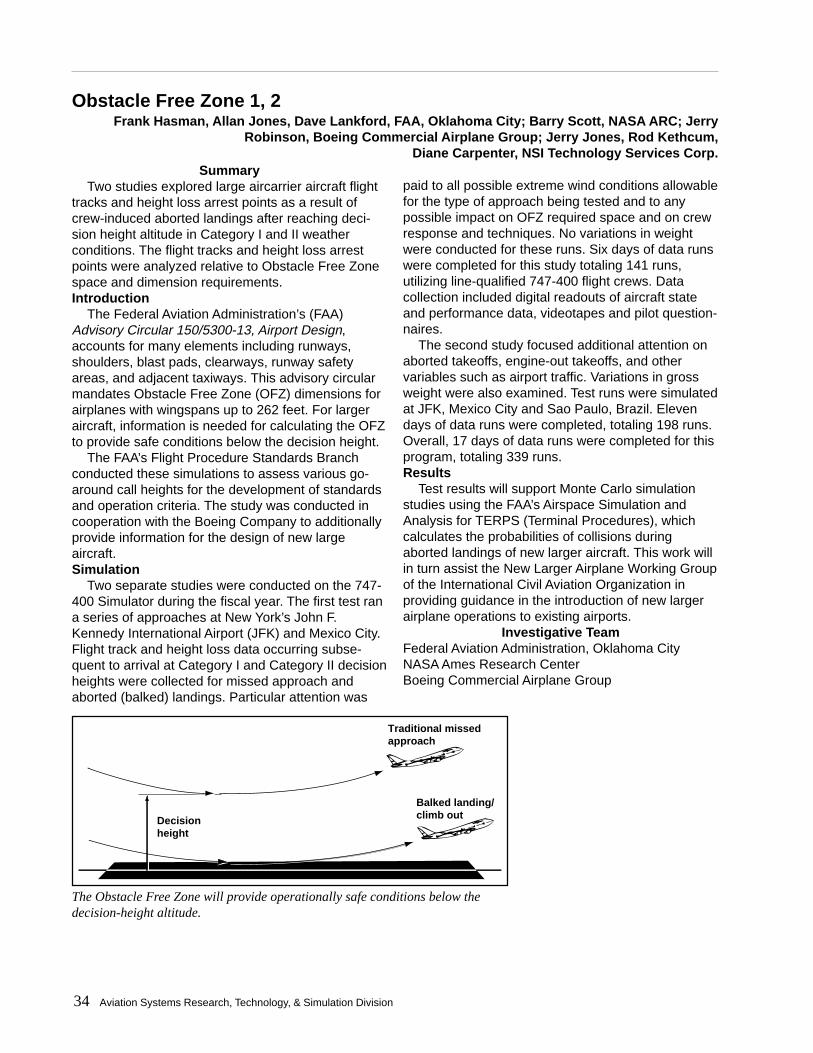
34 Aviation Systems Research, Technology, & Simulation Division
Obstacle Free Zone 1, 2
Traditional missedapproach
Balked landing/climb outDecision
height
The Obstacle Free Zone will provide operationally safe conditions below thedecision-height altitude.
Frank Hasman, Allan Jones, Dave Lankford, FAA, Oklahoma City; Barry Scott, NASA ARC; JerryRobinson, Boeing Commercial Airplane Group; Jerry Jones, Rod Kethcum,
Diane Carpenter, NSI Technology Services Corp.Summary
Two studies explored large aircarrier aircraft flighttracks and height loss arrest points as a result ofcrew-induced aborted landings after reaching deci-sion height altitude in Category I and II weatherconditions. The flight tracks and height loss arrestpoints were analyzed relative to Obstacle Free Zonespace and dimension requirements.Introduction
The Federal Aviation Administration’s (FAA)Advisory Circular 150/5300-13, Airport Design,accounts for many elements including runways,shoulders, blast pads, clearways, runway safetyareas, and adjacent taxiways. This advisory circularmandates Obstacle Free Zone (OFZ) dimensions forairplanes with wingspans up to 262 feet. For largeraircraft, information is needed for calculating the OFZto provide safe conditions below the decision height.
The FAA’s Flight Procedure Standards Branchconducted these simulations to assess various go-around call heights for the development of standardsand operation criteria. The study was conducted incooperation with the Boeing Company to additionallyprovide information for the design of new largeaircraft.Simulation
Two separate studies were conducted on the 747-400 Simulator during the fiscal year. The first test rana series of approaches at New York’s John F.Kennedy International Airport (JFK) and Mexico City.Flight track and height loss data occurring subse-quent to arrival at Category I and Category II decisionheights were collected for missed approach andaborted (balked) landings. Particular attention was
paid to all possible extreme wind conditions allowablefor the type of approach being tested and to anypossible impact on OFZ required space and on crewresponse and techniques. No variations in weightwere conducted for these runs. Six days of data runswere completed for this study totaling 141 runs,utilizing line-qualified 747-400 flight crews. Datacollection included digital readouts of aircraft stateand performance data, videotapes and pilot question-naires.
The second study focused additional attention onaborted takeoffs, engine-out takeoffs, and othervariables such as airport traffic. Variations in grossweight were also examined. Test runs were simulatedat JFK, Mexico City and Sao Paulo, Brazil. Elevendays of data runs were completed, totaling 198 runs.Overall, 17 days of data runs were completed for thisprogram, totaling 339 runs.Results
Test results will support Monte Carlo simulationstudies using the FAA’s Airspace Simulation andAnalysis for TERPS (Terminal Procedures), whichcalculates the probabilities of collisions duringaborted landings of new larger aircraft. This work willin turn assist the New Larger Airplane Working Groupof the International Civil Aviation Organization inproviding guidance in the introduction of new largerairplane operations to existing airports.
Investigative TeamFederal Aviation Administration, Oklahoma CityNASA Ames Research CenterBoeing Commercial Airplane Group
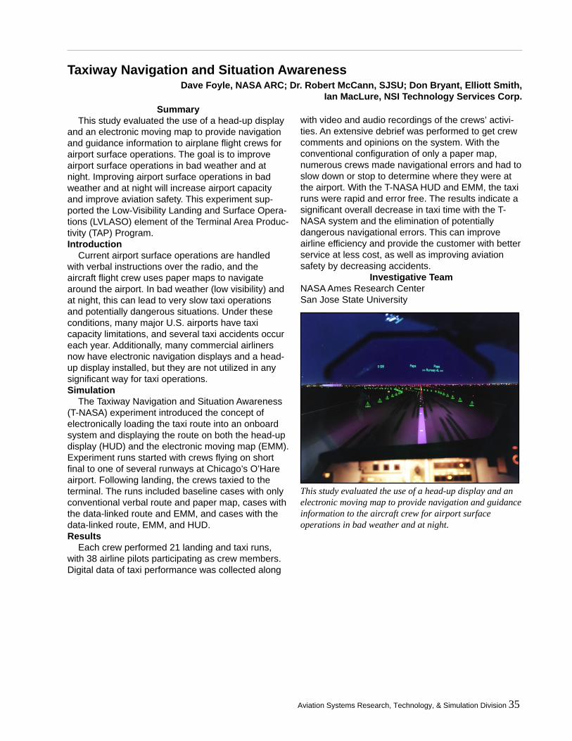
Aviation Systems Research, Technology, & Simulation Division 35
Taxiway Navigation and Situation Awareness
SummaryThis study evaluated the use of a head-up display
and an electronic moving map to provide navigationand guidance information to airplane flight crews forairport surface operations. The goal is to improveairport surface operations in bad weather and atnight. Improving airport surface operations in badweather and at night will increase airport capacityand improve aviation safety. This experiment sup-ported the Low-Visibility Landing and Surface Opera-tions (LVLASO) element of the Terminal Area Produc-tivity (TAP) Program.Introduction
Current airport surface operations are handledwith verbal instructions over the radio, and theaircraft flight crew uses paper maps to navigatearound the airport. In bad weather (low visibility) andat night, this can lead to very slow taxi operationsand potentially dangerous situations. Under theseconditions, many major U.S. airports have taxicapacity limitations, and several taxi accidents occureach year. Additionally, many commercial airlinersnow have electronic navigation displays and a head-up display installed, but they are not utilized in anysignificant way for taxi operations.Simulation
The Taxiway Navigation and Situation Awareness(T-NASA) experiment introduced the concept ofelectronically loading the taxi route into an onboardsystem and displaying the route on both the head-updisplay (HUD) and the electronic moving map (EMM).Experiment runs started with crews flying on shortfinal to one of several runways at Chicago’s O’Hareairport. Following landing, the crews taxied to theterminal. The runs included baseline cases with onlyconventional verbal route and paper map, cases withthe data-linked route and EMM, and cases with thedata-linked route, EMM, and HUD.Results
Each crew performed 21 landing and taxi runs,with 38 airline pilots participating as crew members.Digital data of taxi performance was collected along
with video and audio recordings of the crews’ activi-ties. An extensive debrief was performed to get crewcomments and opinions on the system. With theconventional configuration of only a paper map,numerous crews made navigational errors and had toslow down or stop to determine where they were atthe airport. With the T-NASA HUD and EMM, the taxiruns were rapid and error free. The results indicate asignificant overall decrease in taxi time with the T-NASA system and the elimination of potentiallydangerous navigational errors. This can improveairline efficiency and provide the customer with betterservice at less cost, as well as improving aviationsafety by decreasing accidents.
Investigative TeamNASA Ames Research CenterSan Jose State University
Dave Foyle, NASA ARC; Dr. Robert McCann, SJSU; Don Bryant, Elliott Smith,Ian MacLure, NSI Technology Services Corp.
This study evaluated the use of a head-up display and anelectronic moving map to provide navigation and guidanceinformation to the aircraft crew for airport surfaceoperations in bad weather and at night.
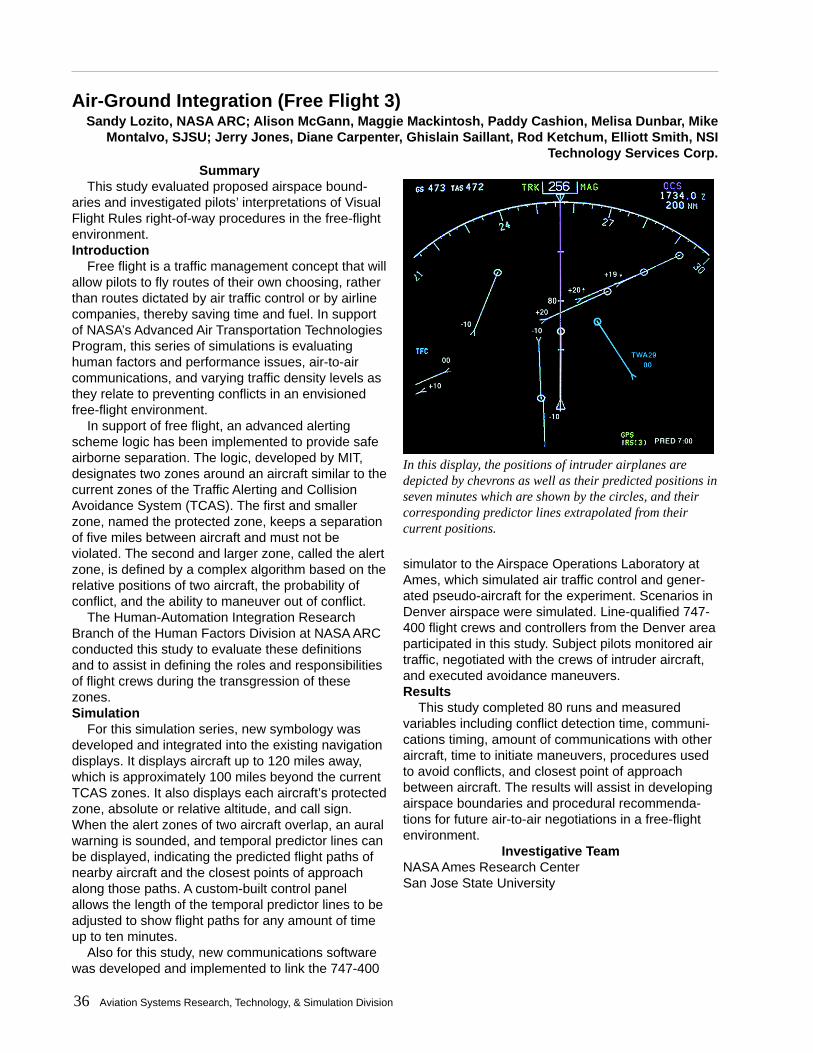
36 Aviation Systems Research, Technology, & Simulation Division
Air-Ground Integration (Free Flight 3)
In this display, the positions of intruder airplanes aredepicted by chevrons as well as their predicted positions inseven minutes which are shown by the circles, and theircorresponding predictor lines extrapolated from theircurrent positions.
Sandy Lozito, NASA ARC; Alison McGann, Maggie Mackintosh, Paddy Cashion, Melisa Dunbar, MikeMontalvo, SJSU; Jerry Jones, Diane Carpenter, Ghislain Saillant, Rod Ketchum, Elliott Smith, NSI
Technology Services Corp.Summary
This study evaluated proposed airspace bound-aries and investigated pilots’ interpretations of VisualFlight Rules right-of-way procedures in the free-flightenvironment.Introduction
Free flight is a traffic management concept that willallow pilots to fly routes of their own choosing, ratherthan routes dictated by air traffic control or by airlinecompanies, thereby saving time and fuel. In supportof NASA’s Advanced Air Transportation TechnologiesProgram, this series of simulations is evaluatinghuman factors and performance issues, air-to-aircommunications, and varying traffic density levels asthey relate to preventing conflicts in an envisionedfree-flight environment.
In support of free flight, an advanced alertingscheme logic has been implemented to provide safeairborne separation. The logic, developed by MIT,designates two zones around an aircraft similar to thecurrent zones of the Traffic Alerting and CollisionAvoidance System (TCAS). The first and smallerzone, named the protected zone, keeps a separationof five miles between aircraft and must not beviolated. The second and larger zone, called the alertzone, is defined by a complex algorithm based on therelative positions of two aircraft, the probability ofconflict, and the ability to maneuver out of conflict.
The Human-Automation Integration ResearchBranch of the Human Factors Division at NASA ARCconducted this study to evaluate these definitionsand to assist in defining the roles and responsibilitiesof flight crews during the transgression of thesezones.Simulation
For this simulation series, new symbology wasdeveloped and integrated into the existing navigationdisplays. It displays aircraft up to 120 miles away,which is approximately 100 miles beyond the currentTCAS zones. It also displays each aircraft’s protectedzone, absolute or relative altitude, and call sign.When the alert zones of two aircraft overlap, an auralwarning is sounded, and temporal predictor lines canbe displayed, indicating the predicted flight paths ofnearby aircraft and the closest points of approachalong those paths. A custom-built control panelallows the length of the temporal predictor lines to beadjusted to show flight paths for any amount of timeup to ten minutes.
Also for this study, new communications softwarewas developed and implemented to link the 747-400
simulator to the Airspace Operations Laboratory atAmes, which simulated air traffic control and gener-ated pseudo-aircraft for the experiment. Scenarios inDenver airspace were simulated. Line-qualified 747-400 flight crews and controllers from the Denver areaparticipated in this study. Subject pilots monitored airtraffic, negotiated with the crews of intruder aircraft,and executed avoidance maneuvers.Results
This study completed 80 runs and measuredvariables including conflict detection time, communi-cations timing, amount of communications with otheraircraft, time to initiate maneuvers, procedures usedto avoid conflicts, and closest point of approachbetween aircraft. The results will assist in developingairspace boundaries and procedural recommenda-tions for future air-to-air negotiations in a free-flightenvironment.
Investigative TeamNASA Ames Research CenterSan Jose State University
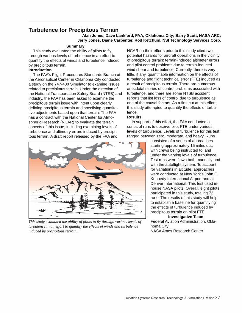
Aviation Systems Research, Technology, & Simulation Division 37
Turbulence for Precipitous Terrain
SummaryThis study evaluated the ability of pilots to fly
through various levels of turbulence in an effort toquantify the effects of winds and turbulence inducedby precipitous terrain.Introduction
The FAA’s Flight Procedures Standards Branch atthe Aeronautical Center in Oklahoma City conducteda study on the 747-400 Simulator to examine issuesrelated to precipitous terrain. Under the direction ofthe National Transportation Safety Board (NTSB) andindustry, the FAA has been asked to examine theprecipitous terrain issue with intent upon clearlydefining precipitous terrain and specifying quantita-tive adjustments based upon that terrain. The FAAhas a contract with the National Center for Atmo-spheric Research (NCAR) to evaluate the terrainaspects of this issue, including examining levels ofturbulence and altimetry errors induced by precipi-tous terrain. A draft report released by the FAA and
NCAR on their efforts prior to this study cited twopotential hazards for aircraft operations in the vicinityof precipitous terrain: terrain-induced altimeter errorsand pilot control problems due to terrain-inducedwind shear and turbulence. Currently, there is verylittle, if any, quantifiable information on the effects ofturbulence and flight technical error (FTE) induced asa result of precipitous terrain. There are numerousanecdotal stories of control problems associated withturbulence, and there are some NTSB accidentreports that list loss of control due to turbulence asone of the causal factors. As a first cut at this effort,this study attempted to quantify the effects of turbu-lence.Results
In support of this effort, the FAA conducted aseries of runs to observe pilot FTE under variouslevels of turbulence. Levels of turbulence for this testranged between zero, moderate, and heavy. Runs
consisted of a series of approachesstarting approximately 15 miles out,with crews being instructed to landunder the varying levels of turbulence.Test runs were flown both manually andwith the autoflight system. To accountfor variations in altitude, approacheswere conducted at New York’s John F.Kennedy International Airport and atDenver International. This test used in-house NASA pilots. Overall, eight pilotsparticipated in this study, totaling 72runs. The results of this study will helpto establish a baseline for quantifyingthe effects of turbulence induced byprecipitous terrain on pilot FTE.
Investigative TeamFederal Aviation Administration, Okla-homa CityNASA Ames Research Center
This study evaluated the ability of pilots to fly through various levels ofturbulence in an effort to quantify the effects of winds and turbulenceinduced by precipitous terrain.
Alan Jones, Dave Lankford, FAA, Oklahoma City; Barry Scott, NASA ARC;Jerry Jones, Diane Carpenter, Rod Ketchum, NSI Technology Services Corp.
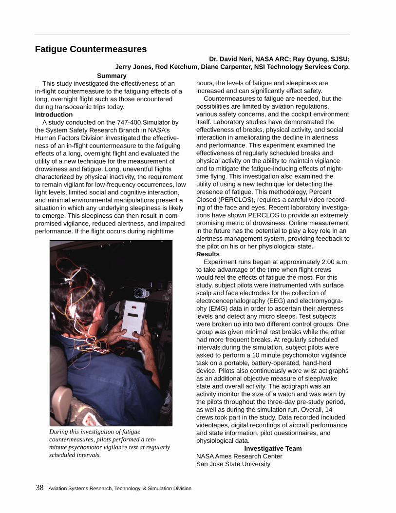
38 Aviation Systems Research, Technology, & Simulation Division
Fatigue Countermeasures
SummaryThis study investigated the effectiveness of an
in-flight countermeasure to the fatiguing effects of along, overnight flight such as those encounteredduring transoceanic trips today.Introduction
A study conducted on the 747-400 Simulator bythe System Safety Research Branch in NASA’sHuman Factors Division investigated the effective-ness of an in-flight countermeasure to the fatiguingeffects of a long, overnight flight and evaluated theutility of a new technique for the measurement ofdrowsiness and fatigue. Long, uneventful flightscharacterized by physical inactivity, the requirementto remain vigilant for low-frequency occurrences, lowlight levels, limited social and cognitive interaction,and minimal environmental manipulations present asituation in which any underlying sleepiness is likelyto emerge. This sleepiness can then result in com-promised vigilance, reduced alertness, and impairedperformance. If the flight occurs during nighttime
hours, the levels of fatigue and sleepiness areincreased and can significantly effect safety.
Countermeasures to fatigue are needed, but thepossibilities are limited by aviation regulations,various safety concerns, and the cockpit environmentitself. Laboratory studies have demonstrated theeffectiveness of breaks, physical activity, and socialinteraction in ameliorating the decline in alertnessand performance. This experiment examined theeffectiveness of regularly scheduled breaks andphysical activity on the ability to maintain vigilanceand to mitigate the fatigue-inducing effects of night-time flying. This investigation also examined theutility of using a new technique for detecting thepresence of fatigue. This methodology, PercentClosed (PERCLOS), requires a careful video record-ing of the face and eyes. Recent laboratory investiga-tions have shown PERCLOS to provide an extremelypromising metric of drowsiness. Online measurementin the future has the potential to play a key role in analertness management system, providing feedback tothe pilot on his or her physiological state.Results
Experiment runs began at approximately 2:00 a.m.to take advantage of the time when flight crewswould feel the effects of fatigue the most. For thisstudy, subject pilots were instrumented with surfacescalp and face electrodes for the collection ofelectroencephalography (EEG) and electromyogra-phy (EMG) data in order to ascertain their alertnesslevels and detect any micro sleeps. Test subjectswere broken up into two different control groups. Onegroup was given minimal rest breaks while the otherhad more frequent breaks. At regularly scheduledintervals during the simulation, subject pilots wereasked to perform a 10 minute psychomotor vigilancetask on a portable, battery-operated, hand-helddevice. Pilots also continuously wore wrist actigraphsas an additional objective measure of sleep/wakestate and overall activity. The actigraph was anactivity monitor the size of a watch and was worn bythe pilots throughout the three-day pre-study period,as well as during the simulation run. Overall, 14crews took part in the study. Data recorded includedvideotapes, digital recordings of aircraft performanceand state information, pilot questionnaires, andphysiological data.
Investigative TeamNASA Ames Research CenterSan Jose State University
Dr. David Neri, NASA ARC; Ray Oyung, SJSU;Jerry Jones, Rod Ketchum, Diane Carpenter, NSI Technology Services Corp.
During this investigation of fatiguecountermeasures, pilots performed a ten-minute psychomotor vigilance test at regularlyscheduled intervals.

Aviation Systems Research, Technology, & Simulation Division 39
Propulsion Controlled Aircraft 4 (Ultralite)
The PCA concept is to control a damaged aircraft through the use of throttles only.
SummarySeveral airline and military aircraft have crashed
after having systems fail that cause partial or com-plete loss of control of the conventional controlsurfaces (rudder, aileron, elevator, flaps, slats). ThePropulsion Controlled Aircraft system utilizes enginethrust only to control the aircraft and safely land. Thisexperiment studied a simplified Propulsion ControlledAircraft design (Ultralite) that may be affordable forretrofit into existing airline fleets.Introduction
The NASA Propulsion Controlled Aircraft (PCA)research program has developed engine controlsystems that provide excellent control capabilities tovehicles that have lost conventional controls. Thisresearch has included past experiments on the ACFSand 747 simulators as well as flight tests on aMcDonnell Douglas MD-11 aircraft. The cost toretrofit these complete systems into existing airlinefleets would be veryhigh. This PCAexperiment investi-gated differentlevels of automationto evaluate theusefulness ofsystems that couldpotentially beretrofitted toexisting aircraft atsignificantly lowercost.
The specificautomation configu-rations investigatedincluded automaticsymmetric andmanual asymmetricengine thrustcontrol (called PCAUltralite), manualsymmetric andasymmetric engine
thrust control, with the use of either conventionalPCA or PCA flight director mode.Results
Test pilots from three NASA Centers, the FAA, theAirline Pilots Association, and several airlines allevaluated the system. Early results indicate that bothflight director modes significantly improved the crew’sability to land safely, and the PCA Ultralite throttlesystem also helped significantly. Additional experi-ments are planned for the 747-400 simulator atNASA Ames and for flight tests on board the NASA757 aircraft as part of the Aviation Safety Program.
Investigative TeamNASA Ames Research CenterNASA Dryden Flight Research CenterJohn S. Bull, Independent ContractorFoothill DeAnza Community College
John Kaneshige, NASA ARC;Don Bryant, Diane Carpenter, NSI Technology Services Corp.
Throttle Commands
Pilot Inputs
PCAControl Laws
FEE T ( ) M E TE R
–5 00
DG ( ) T RK
220HDG V /S
BankLimit
5 25
Hold V/S
DN
UP
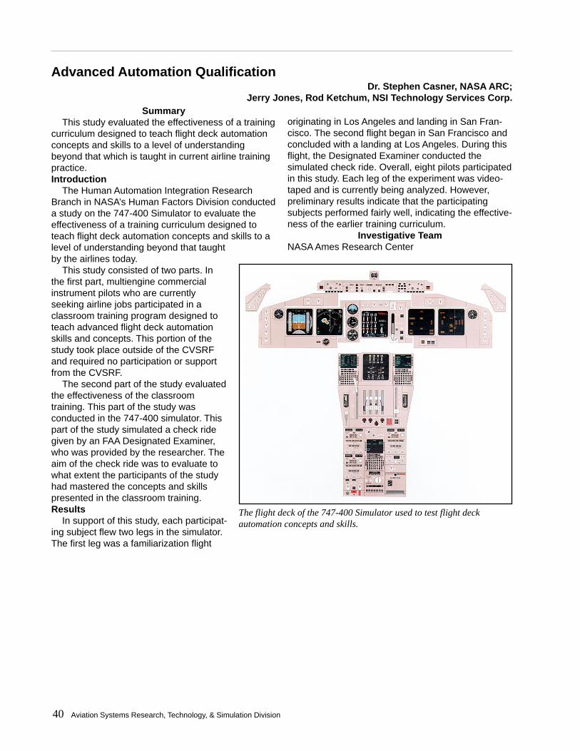
40 Aviation Systems Research, Technology, & Simulation Division
Advanced Automation Qualification
SummaryThis study evaluated the effectiveness of a training
curriculum designed to teach flight deck automationconcepts and skills to a level of understandingbeyond that which is taught in current airline trainingpractice.Introduction
The Human Automation Integration ResearchBranch in NASA’s Human Factors Division conducteda study on the 747-400 Simulator to evaluate theeffectiveness of a training curriculum designed toteach flight deck automation concepts and skills to alevel of understanding beyond that taughtby the airlines today.
This study consisted of two parts. Inthe first part, multiengine commercialinstrument pilots who are currentlyseeking airline jobs participated in aclassroom training program designed toteach advanced flight deck automationskills and concepts. This portion of thestudy took place outside of the CVSRFand required no participation or supportfrom the CVSRF.
The second part of the study evaluatedthe effectiveness of the classroomtraining. This part of the study wasconducted in the 747-400 simulator. Thispart of the study simulated a check ridegiven by an FAA Designated Examiner,who was provided by the researcher. Theaim of the check ride was to evaluate towhat extent the participants of the studyhad mastered the concepts and skillspresented in the classroom training.Results
In support of this study, each participat-ing subject flew two legs in the simulator.The first leg was a familiarization flight
originating in Los Angeles and landing in San Fran-cisco. The second flight began in San Francisco andconcluded with a landing at Los Angeles. During thisflight, the Designated Examiner conducted thesimulated check ride. Overall, eight pilots participatedin this study. Each leg of the experiment was video-taped and is currently being analyzed. However,preliminary results indicate that the participatingsubjects performed fairly well, indicating the effective-ness of the earlier training curriculum.
Investigative TeamNASA Ames Research Center
Dr. Stephen Casner, NASA ARC;Jerry Jones, Rod Ketchum, NSI Technology Services Corp.
The flight deck of the 747-400 Simulator used to test flight deckautomation concepts and skills.

Aviation Systems Research, Technology, & Simulation Division 41

42 Aviation Systems Research, Technology, & Simulation Division
Aviation Systems Research, Technology, & Simulation Division 43
State-of-the-ArtSimulation Facilities
Providing advanced flightsimulation capabilities requirescontinual modernization. To keeppace with evolving customerneeds, SimLab strives to optimizethe simulation systems, fromcockpits to computers to technol-ogy for real-time networking withflight simulators and laboratories inremote locations.
TECHNOLOGY UPGRADE
PROJECTS
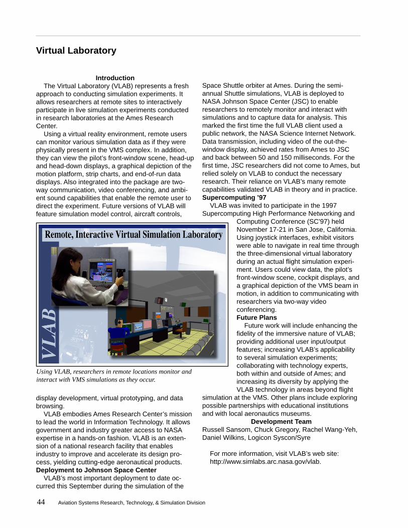
44 Aviation Systems Research, Technology, & Simulation Division
Virtual Laboratory
IntroductionThe Virtual Laboratory (VLAB) represents a fresh
approach to conducting simulation experiments. Itallows researchers at remote sites to interactivelyparticipate in live simulation experiments conductedin research laboratories at the Ames ResearchCenter.
Using a virtual reality environment, remote userscan monitor various simulation data as if they werephysically present in the VMS complex. In addition,they can view the pilot’s front-window scene, head-upand head-down displays, a graphical depiction of themotion platform, strip charts, and end-of-run datadisplays. Also integrated into the package are two-way communication, video conferencing, and ambi-ent sound capabilities that enable the remote user todirect the experiment. Future versions of VLAB willfeature simulation model control, aircraft controls,
display development, virtual prototyping, and databrowsing.
VLAB embodies Ames Research Center’s missionto lead the world in Information Technology. It allowsgovernment and industry greater access to NASAexpertise in a hands-on fashion. VLAB is an exten-sion of a national research facility that enablesindustry to improve and accelerate its design pro-cess, yielding cutting-edge aeronautical products.Deployment to Johnson Space Center
VLAB’s most important deployment to date oc-curred this September during the simulation of the
Space Shuttle orbiter at Ames. During the semi-annual Shuttle simulations, VLAB is deployed toNASA Johnson Space Center (JSC) to enableresearchers to remotely monitor and interact withsimulations and to capture data for analysis. Thismarked the first time the full VLAB client used apublic network, the NASA Science Internet Network.Data transmission, including video of the out-the-window display, achieved rates from Ames to JSCand back between 50 and 150 milliseconds. For thefirst time, JSC researchers did not come to Ames, butrelied solely on VLAB to conduct the necessaryresearch. Their reliance on VLAB’s many remotecapabilities validated VLAB in theory and in practice.Supercomputing ’97
VLAB was invited to participate in the 1997Supercomputing High Performance Networking and
Computing Conference (SC’97) heldNovember 17-21 in San Jose, California.Using joystick interfaces, exhibit visitorswere able to navigate in real time throughthe three-dimensional virtual laboratoryduring an actual flight simulation experi-ment. Users could view data, the pilot’sfront-window scene, cockpit displays, anda graphical depiction of the VMS beam inmotion, in addition to communicating withresearchers via two-way videoconferencing.Future Plans
Future work will include enhancing thefidelity of the immersive nature of VLAB;providing additional user input/outputfeatures; increasing VLAB’s applicabilityto several simulation experiments;collaborating with technology experts,both within and outside of Ames; andincreasing its diversity by applying theVLAB technology in areas beyond flight
simulation at the VMS. Other plans include exploringpossible partnerships with educational institutionsand with local aeronautics museums.
Development TeamRussell Sansom, Chuck Gregory, Rachel Wang-Yeh,Daniel Wilkins, Logicon Syscon/Syre
For more information, visit VLAB’s web site:http://www.simlabs.arc.nasa.gov/vlab.
Using VLAB, researchers in remote locations monitor andinteract with VMS simulations as they occur.

Aviation Systems Research, Technology, & Simulation Division 45
Out-the-Window 2000 Plus
SummaryTo greatly enhance the real-time out-the-window
image capabilities of the VMS, an engineeringproject, designated Out-the-Window 2000 Plus,combined two image generators into a single,powerful unit at a significant savings over purchasingan equivalent system.Introduction
Through 1997, the VMS real-time out-the-windowscenery was generated by an Evans and SutherlandCT5A and by an Evans and Sutherland ImageGenerator (ESIG) 3000. The CT5A was limited tothree video channels, low object counts, andtextureless polygons, which no longer met researcherdemands for realism or scene detail in visual cueing.Due to the low performance of the CT5A, demandson the ESIG 3000 escalated. Out-the-Window 2000Plus (OTW2K+) was formed to replace the CT5A witha system that would provide state-of-the-art imagerybeyond the year 2000.
Requirements for the new system included com-patibility with existing legacy software and with anextensive library of visual databases. Implementationneeded to occur without significant change to theinterface with the rest of the simulation system. Onlycommercial off-the-shelf systems would be consid-ered to avoid the high cost, complexity, and mainte-nance of a custom-built system. Additionally,OTW2K+ was the first VMS project to follow ISO9000 procedures.Project Description
After the establishment of formal project require-ments, a surplus three-channel ESIG 4530 becameavailable from NASA Johnson Space Center (JSC).Project personnel determined that the surplus unitand an additional new unit could be acquired andmerged into a single system, fulfilling the projectrequirements at a significant savings over the alter-natives. The VMS purchased the 4530 from JSC andcontracted with Evans and Sutherland to supply anew two-channel ESIG 4530. OTW2K+ then inte-grated the two machines.
The 4500 series software required several modifi-cations. The network interface software was changedto allow connection to the multi-node network byignoring broadcast packets. The video generationsoftware was modified to enable operation in externalsync mode and with the XKD 8000 out-the-windowmonitors. Evans and Sutherland modified somesoftware, and software was also incorporated fromthe ESIG 3000 on site.
ResultsThe new system underwent an extensive series of
tests and became operational without disruption tothe simulation schedule on April 14, 1998. ISO 9000standards were met and included the procurement ofsparing and maintenance, as well as training forpersonnel involved in visual database development,system hardware maintenance, and simulationengineering.
By acquiring and physically merging two low-costimage generators and customizing the systemsoftware, the VMS efficiently produced a powerfulmachine with five video channels. The new systemfeatures high resolution, MIPS texture, and highobject counts. With dual CPUs and dual VME buses,the new system can be configured for two indepen-dent eye points.
Development TeamDoug Greaves, NASA ARC; Timothy Trammell,Ernest Inn, Cary Wales, Jeffery Dewey, LogiconSyscon/Syre
Out-the-Window 2000 Plus (OTW2K+) was formed toreplace the CT5A with a system that would provide state-of-the-art imagery beyond the year 2000. The new systemfeatures high resolution, MIPS texture, and high objectcounts.

46 Aviation Systems Research, Technology, & Simulation Division
Host Computer Upgrade
SummaryTo meet the computing requirements of today’s
most demanding simulations, Host Computer Up-grade ’98 replaced existing host computers with newsystems that exhibit the potential to meet the simula-tion needs of the VMS well into the new century.Introduction
Host Computer Upgrade ’98 integrated new,higher-performance host computers into the VMScomplex. The new systems replaced host computersthat could not meet the anticipated computingrequirements of three specific simulations scheduledfor FY98 and FY99. The requirements of the simula-tions called for drastic increases of between 1.5 to2.5 times the performance of the existing systems.The project had three principal requirements: com-puting power capable of meeting future simulationneeds, functionality similar to that provided by thesystems being replaced, and the ability to obtainrepairs in the same time frame.Performance
Considering that the current computers had beenin place less than three years and that they repre-sented a twofold increase in speed over the previousmachines, meeting the specifications was problem-atic. However, due to the computer industry’s im-provements in chip computing frequencies andfeature capabilities, it was possible to purchasecomputer systems with the necessary performancefrom the manufacturer of the existing machines,thereby meeting all three requirements.
The new hosts are Digital Equipment Corp.AlphaServer 1000A 5/500 machines, replacingAlphaServer 1000 4/233s. Benchmark figures fromthe Standard Performance Evaluation Corporation
(SPEC, a standardization body) indicated a 3.3 timesimprovement in speed. Using the samemanufacturer’s operating system allowed the sameuser functionality features. The repair time require-ment was maintained easily across machines withidentical warranties. This solution provided a rela-tively easy means of satisfying the requirements,although there were some changes in the laboratoryinterfaces that required upgrade to and modificationof certain input/output (I/O) circuit board sets.
The performance increase of the operationalsystems easily exceeded the requirements of theFY98 simulations. Taken together with the CAMACinterface to the cockpit and labs, the VMS system iscapable of frame times of less than one millisecondwhen only I/O is performed with the motion, labora-tory, and cockpit subsystems. Adding the typicalaircraft model allows frame times as short as 2milliseconds. As a practical matter, most simulationsare run at longer frame times, such as 12.5 millisec-onds (80 cycles per second), which is more compat-ible with the 16 2/3 millisecond field time of theassociated graphics generators.Results
The integration of the new systems was completedin the motion-base lab and in one of the supportinglaboratories. An additional laboratory upgrade isanticipated for FY99. The new systems are capableof speeds 2.5 times faster than the systems theyreplaced. By the end of FY98, the new host computersystem had been used successfully in both of theyear’s required simulations.
Development TeamWilliam Cleveland, NASA ARC; Bosco Dias, Estela
Hernandez, Hai Huynh, MartinPethtel, Logicon Syscon/Syre
The host simulation computers interface to the laboratory, cockpit, andmotion systems. The new host provides frame times down to two milliseconds,depending on the complexity of the aircraft model.
Alpha 5/500
CockpitLaboratory Motion
VME I/F
CAMAC I/O
Data "Highway"

Aviation Systems Research, Technology, & Simulation Division 47
Real-Time Network Upgrade
SummaryAn upgrade of the real-time network at VMS
significantly increased network performance, func-tionality, and configurability while allowing for futureupgrades to developing network technologies.Introduction
Until recently, switching for the real-time network atVMS was controlled by two 10Base5 half-duplexswitches. Under this system, network connections tothe three host computers approached saturation. Toremedy the situation, and to make the network morefunctional and more configurable, the switches werereplaced by a Xylan OmniSwitch 5.Features and Performance• Full-duplex 100 megabits per second (Mbps)Ethernet (Fast Ethernet) - boosts the speed of hostcomputer connections by approximately 20 times andeliminates Ethernet collisions. Response time of theEvans and Sutherland Image Generators (ESIGs) issignificantly more predictable. Attempts to load thenetwork revealed no measurable changes to theresponse time of the ESIGs or to the input/outputframe timing of the host computer’s software.• Thirty-six 10/100 auto sensing ports - increase thenumber of devices that can be networked. Portscommunicate at 10 Mbps or 100 Mbps, according toeach device’s capability.• Low, predictable latency - ensures that packets arepassed quickly and consistently.• Console interface - allows engineers to monitor thesystem status, change configuration settings, saveconfiguration files, and upgrade the firmware.• Out-of-band packet analysis - makes possible theanalysis of network performance without disruption toreal-time operation.• Address manipulation - enables the assignment ofpermanent addresses and the configuration ofaddress aging.
• Virtual Local Area Network (VLAN) capability -allows the 36 ports to be split into two isolatednetworks; 34 ports were assigned to the real-timenetwork and 2 ports to the development network.• Modular components - enable easy expansion andupgrades, including firmware.Results
The real-time network upgrade replaced a dual 10Mbps half-duplex network with a highly configurable10/100 Mbps full-duplex network. Transition to thenew network was achieved with no disruption to theVMS simulation schedule. The increased perfor-mance of the host connection allows more Ethernetinput/output to be added to the host computersoftware if needed. The new system provides supe-rior monitoring and control capabilities. Lastly, themodular components allow for expansion of theEthernet ports and for upgrade to future networktechnologies.
Principal ContributorMartin Pethtel, Logicon Syscon/Syre
The Real-Time Network switch (far right) and two networkmanagement stations.
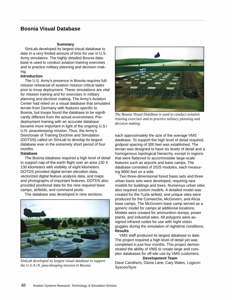
48 Aviation Systems Research, Technology, & Simulation Division
Bosnia Visual Database
SummarySimLab developed its largest visual database to
date in a very limited amount of time for use in U.S.Army simulators. The highly detailed Bosnia data-base is used to conduct aviation training exercisesand to practice military planning and decision mak-ing.Introduction
The U.S. Army’s presence in Bosnia requires full-mission rehearsal of aviation mission critical tasksprior to troop deployment. These simulations are vitalfor mission training and for exercises in militaryplanning and decision making. The Army’s AviationCenter had relied on a visual database that simulatedterrain from Germany with features specific toBosnia, but troops found the database to be signifi-cantly different from the actual environment. Pre-deployment training with an accurate databasebecame more important in light of the ongoing U.S./U.N. peacekeeping mission. Thus, the Army’sDirectorate of Training Doctrine and Simulation(DOTDS) called on SimLab to develop its largestdatabase ever in the extremely short period of fourmonths.Database
The Bosnia database required a high level of detailto support nap-of-the-earth flight over an area 130 X130 kilometers with visibility of eight kilometers.DOTDS provided digital terrain elevation data,vectorized digital feature analysis data, and mapsand photographs of important features. DOTDS alsoprovided positional data for the nine required basecamps, airfields, and command posts.
The database was developed in nine sections,
each approximately the size of the average VMSdatabase. To support the high level of detail required,gridpost spacing of 300 feet was established. Theterrain was designed to have six levels of detail and ahomogenous topological hierarchy, except in regionsthat were flattened to accommodate large-scalefeatures such as airports and base camps. Thedatabase consisted of 2025 modules, each measur-ing 9600 feet on a side.
Two three-dimensional forest basis sets and threeurban basis sets were developed, requiring newmodels for buildings and trees. Numerous urban sitesalso required custom models. A detailed model wascreated for the Tuzla airfield, and unique sites wereproduced for the Comanche, McGovern, and Aliciabase camps. The McGovern base camp served as ageneric model for camps at additional locations.Models were created for ammunition dumps, powerplants, and industrial sites. All polygons were as-signed infrared codes for use with night visiongoggles during the simulation of nighttime conditions.Results
VMS staff produced its largest database to date.The project required a high level of detail yet wascompleted in just four months. This project demon-strated the ability of VMS to create large and com-plex databases for off-site use by VMS customers.
Development TeamDave Carothers, Gloria Lane, Cary Wales, LogiconSyscon/Syre
SimLab developed its largest visual database to supportthe U.S./U.N. peacekeeping mission in Bosnia.
The Bosnia Visual Database is used to conduct aviationtraining exercises and to practice military planning anddecision making.

Aviation Systems Research, Technology, & Simulation Division 49
Joint FAA/Army/NASA Interoperability Demonstration
SummaryThe Department of Defense is developing a new
method for interconnecting simulations called HighLevel Architecture and has mandated that all Depart-ment of Defense simulators use this system. In orderto evaluate the potential of this new system forassisting NASA in performing aviation research, atest federation was developed with two primarycustomers of the simulation facilities, the U.S. Armyand the Federal Aviation Administration. The teamsuccessfully demonstrated the technology andidentified many strengths and a few potential prob-lems with this new system.Introduction
In order to perform advanced airspace operationsresearch, it is becoming increasingly necessary tointerconnect more and more simulators during oneexperiment. This can be a difficult and time-consum-ing effort. Current methods utilized at NASA ARC andthe Federal Aviation Administration (FAA) TechnicalCenter in New Jersey are based on ad hoc methodsand standards as needed for each experiment. TheDepartment of Defense (DOD) has mandated that fortheir integrated experiments, all simulators will utilizea new system of software and conventions calledHigh Level Architecture (HLA). Personnel from NASAAmes, the FAA, and the U.S. Army (located at Ames)determined that the best method to evaluate thistechnology was to develop a demonstration experi-
ment utilizing components from each facility.Results
The Advanced Concepts Flight Simulator (ACFS)and several desk-top copies of the simulation (calledthe Mini-ACFS) at CVSRF were flown in real-time,networked to the Army’s helicopter simulator andtactical environment simulation and to the FAA’sMicro Target Generation Facility (MTGF), Air TrafficControl Test Federate (ATCTF), and Cockpit Simula-tion Facility (CSF). All aircraft flew conventionalapproaches to San Francisco International Airport.The aircraft generated by the Army and FAA simula-tions were visible on the navigation display as well ason the out-the-window visual system on the ACFS.Timing and performance data were collected andreported to the DOD sponsor for HLA activities, theSimulation Interoperability Standards Organization(SISO). The system provided a good framework fornetworking large numbers of different simulators.
Investigative TeamNASA Ames Research CenterFederal Aviation AdministrationU.S. Army
Project Support TeamMatthew Blake, NASA ARC; Craig Pires, HectorReyes, NSI Technology Services Corporation
CVSRF, in conjunctionwith the FAA and the U.S.Army, demonstrated anew system of softwareand conventions thatinterconnects simulatorsduring a singleexperiment.
Advanced Concepts Flight Simulator
(ACFS)
Existing ATC
Interface
Mini-ACFS Desktop
Simulators
Convert to/from
HLARTI
HLA Gateway
Boeing 747 and other NASA Ames Simulators National
Wide Area Network
Existing Air Traffic Control (ATC) System
In Building Local
EthernetNetwork
Local Ames
Wide Area Network
NASA Pseudo Aircraft System (PAS) Federate
Army Federates
FAA Federates
NASA Components Utilized for JFAN
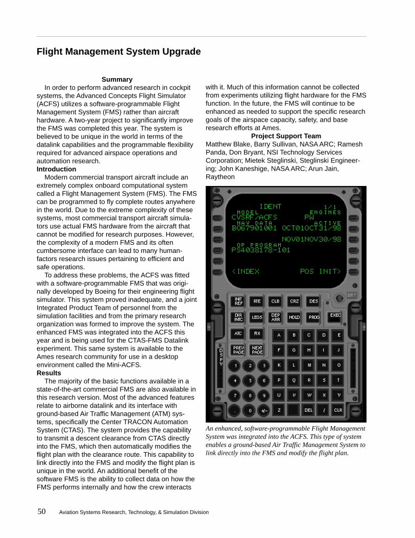
50 Aviation Systems Research, Technology, & Simulation Division
Flight Management System Upgrade
SummaryIn order to perform advanced research in cockpit
systems, the Advanced Concepts Flight Simulator(ACFS) utilizes a software-programmable FlightManagement System (FMS) rather than aircrafthardware. A two-year project to significantly improvethe FMS was completed this year. The system isbelieved to be unique in the world in terms of thedatalink capabilities and the programmable flexibilityrequired for advanced airspace operations andautomation research.Introduction
Modern commercial transport aircraft include anextremely complex onboard computational systemcalled a Flight Management System (FMS). The FMScan be programmed to fly complete routes anywherein the world. Due to the extreme complexity of thesesystems, most commercial transport aircraft simula-tors use actual FMS hardware from the aircraft thatcannot be modified for research purposes. However,the complexity of a modern FMS and its oftencumbersome interface can lead to many human-factors research issues pertaining to efficient andsafe operations.
To address these problems, the ACFS was fittedwith a software-programmable FMS that was origi-nally developed by Boeing for their engineering flightsimulator. This system proved inadequate, and a jointIntegrated Product Team of personnel from thesimulation facilities and from the primary researchorganization was formed to improve the system. Theenhanced FMS was integrated into the ACFS thisyear and is being used for the CTAS-FMS Datalinkexperiment. This same system is available to theAmes research community for use in a desktopenvironment called the Mini-ACFS.Results
The majority of the basic functions available in astate-of-the-art commercial FMS are also available inthis research version. Most of the advanced featuresrelate to airborne datalink and its interface withground-based Air Traffic Management (ATM) sys-tems, specifically the Center TRACON AutomationSystem (CTAS). The system provides the capabilityto transmit a descent clearance from CTAS directlyinto the FMS, which then automatically modifies theflight plan with the clearance route. This capability tolink directly into the FMS and modify the flight plan isunique in the world. An additional benefit of thesoftware FMS is the ability to collect data on how theFMS performs internally and how the crew interacts
with it. Much of this information cannot be collectedfrom experiments utilizing flight hardware for the FMSfunction. In the future, the FMS will continue to beenhanced as needed to support the specific researchgoals of the airspace capacity, safety, and baseresearch efforts at Ames.
Project Support TeamMatthew Blake, Barry Sullivan, NASA ARC; RameshPanda, Don Bryant, NSI Technology ServicesCorporation; Mietek Steglinski, Steglinski Engineer-ing; John Kaneshige, NASA ARC; Arun Jain,Raytheon
An enhanced, software-programmable Flight ManagementSystem was integrated into the ACFS. This type of systemenables a ground-based Air Traffic Management System tolink directly into the FMS and modify the flight plan.
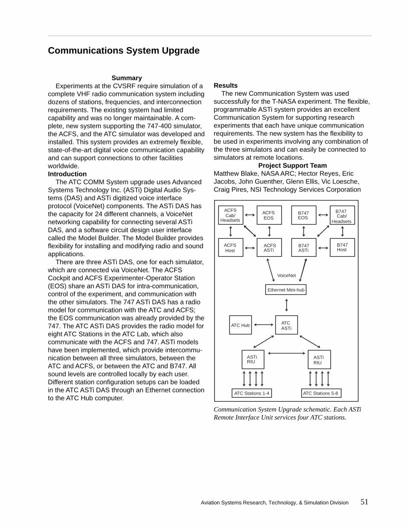
Aviation Systems Research, Technology, & Simulation Division 51
Communications System Upgrade
ATC ASTi
ATC Hub
ATC Stations 1-4 ATC Stations 5-8
Ethernet Mini-hub
VoiceNet
ASTi RIU
ASTi RIU
ACFS Host
ACFS Cab/Headsets
ACFS EOS
ACFS ASTi
B747 Cab/ Headsets
B747 Host
B747 EOS
B747 ASTi
SummaryExperiments at the CVSRF require simulation of a
complete VHF radio communication system includingdozens of stations, frequencies, and interconnectionrequirements. The existing system had limitedcapability and was no longer maintainable. A com-plete, new system supporting the 747-400 simulator,the ACFS, and the ATC simulator was developed andinstalled. This system provides an extremely flexible,state-of-the-art digital voice communication capabilityand can support connections to other facilitiesworldwide.Introduction
The ATC COMM System upgrade uses AdvancedSystems Technology Inc. (ASTi) Digital Audio Sys-tems (DAS) and ASTi digitized voice interfaceprotocol (VoiceNet) components. The ASTi DAS hasthe capacity for 24 different channels, a VoiceNetnetworking capability for connecting several ASTiDAS, and a software circuit design user interfacecalled the Model Builder. The Model Builder providesflexibility for installing and modifying radio and soundapplications.
There are three ASTi DAS, one for each simulator,which are connected via VoiceNet. The ACFSCockpit and ACFS Experimenter-Operator Station(EOS) share an ASTi DAS for intra-communication,control of the experiment, and communication withthe other simulators. The 747 ASTi DAS has a radiomodel for communication with the ATC and ACFS;the EOS communication was already provided by the747. The ATC ASTi DAS provides the radio model foreight ATC Stations in the ATC Lab, which alsocommunicate with the ACFS and 747. ASTi modelshave been implemented, which provide intercommu-nication between all three simulators, between theATC and ACFS, or between the ATC and B747. Allsound levels are controlled locally by each user.Different station configuration setups can be loadedin the ATC ASTi DAS through an Ethernet connectionto the ATC Hub computer.
ResultsThe new Communication System was used
successfully for the T-NASA experiment. The flexible,programmable ASTi system provides an excellentCommunication System for supporting researchexperiments that each have unique communicationrequirements. The new system has the flexibility tobe used in experiments involving any combination ofthe three simulators and can easily be connected tosimulators at remote locations.
Project Support TeamMatthew Blake, NASA ARC; Hector Reyes, EricJacobs, John Guenther, Glenn Ellis, Vic Loesche,Craig Pires, NSI Technology Services Corporation
Communication System Upgrade schematic. Each ASTiRemote Interface Unit services four ATC stations.
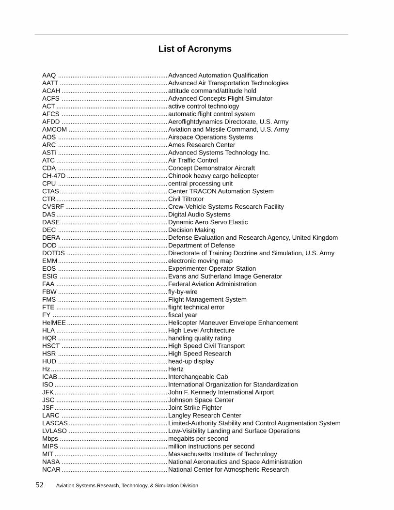
52 Aviation Systems Research, Technology, & Simulation Division
List of Acronyms
AAQ .............................................................Advanced Automation QualificationAATT ............................................................Advanced Air Transportation TechnologiesACAH ........................................................... attitude command/attitude holdACFS ...........................................................Advanced Concepts Flight SimulatorACT .............................................................. active control technologyAFCS ........................................................... automatic flight control systemAFDD ...........................................................Aeroflightdynamics Directorate, U.S. ArmyAMCOM .......................................................Aviation and Missile Command, U.S. ArmyAOS .............................................................Airspace Operations SystemsARC .............................................................Ames Research CenterASTi .............................................................Advanced Systems Technology Inc.ATC ..............................................................Air Traffic ControlCDA .............................................................Concept Demonstrator AircraftCH-47D ........................................................Chinook heavy cargo helicopterCPU ............................................................. central processing unitCTAS ............................................................Center TRACON Automation SystemCTR..............................................................Civil TiltrotorCVSRF .........................................................Crew-Vehicle Systems Research FacilityDAS..............................................................Digital Audio SystemsDASE ...........................................................Dynamic Aero Servo ElasticDEC .............................................................Decision MakingDERA ...........................................................Defense Evaluation and Research Agency, United KingdomDOD .............................................................Department of DefenseDOTDS ........................................................Directorate of Training Doctrine and Simulation, U.S. ArmyEMM............................................................. electronic moving mapEOS .............................................................Experimenter-Operator StationESIG ............................................................Evans and Sutherland Image GeneratorFAA ..............................................................Federal Aviation AdministrationFBW ............................................................. fly-by-wireFMS .............................................................Flight Management SystemFTE .............................................................. flight technical errorFY ................................................................ fiscal yearHelMEE ........................................................Helicopter Maneuver Envelope EnhancementHLA ..............................................................High Level ArchitectureHQR ............................................................. handling quality ratingHSCT ...........................................................High Speed Civil TransportHSR .............................................................High Speed ResearchHUD ............................................................. head-up displayHz .................................................................HertzICAB............................................................. Interchangeable CabISO ............................................................... International Organization for StandardizationJFK............................................................... John F. Kennedy International AirportJSC .............................................................. Johnson Space CenterJSF............................................................... Joint Strike FighterLARC ........................................................... Langley Research CenterLASCAS ....................................................... Limited-Authority Stability and Control Augmentation SystemLVLASO ....................................................... Low-Visibility Landing and Surface OperationsMbps ............................................................megabits per secondMIPS ............................................................million instructions per secondMIT ...............................................................Massachusetts Institute of TechnologyNASA ...........................................................National Aeronautics and Space AdministrationNCAR ...........................................................National Center for Atmospheric Research

Aviation Systems Research, Technology, & Simulation Division 53
NTSB ...........................................................National Transportation Safety BoardOFZ ..............................................................Obstacle Free ZoneOTW2K+ ......................................................Out-the-Window 2000 PlusPCA..............................................................Propulsion Controlled AircraftPIO ............................................................... pilot-induced oscillationPNN ............................................................. polynomial neural networkRCAH ........................................................... rate command/attitude holdSCAS ........................................................... stability and control augmentation systemSGI ...............................................................Silicon Graphics IncorporatedSimFR ..........................................................Simulation Fidelity RequirementsSimLab .........................................................Simulation LaboratoriesSJSU ............................................................San Jose State UniversitySMC ............................................................. structural mode controlSSV ..............................................................Space Shuttle VehicleSTOVL ......................................................... short takeoff/vertical landingTAP ..............................................................Terminal Area ProductivityTCAB ........................................................... Transport CabTCAS ........................................................... Traffic Alerting and Collision Avoidance SystemTERPS .........................................................Terminal ProceduresT-NASA ........................................................Taxiway Navigation and Situation AwarenessUN ................................................................United NationsUSAF ...........................................................United States Air ForceUSN .............................................................United States NavyUSMC ..........................................................United States Marine CorpsVHF .............................................................. very high frequencyVLAB ............................................................Virtual LaboratoryVME .............................................................VersaModule EurocardVMS .............................................................Vertical Motion Simulator
54 Aviation Systems Research, Technology, & Simulation Division
A very brief description of the Aviation Sys-tems Research, Technology, & SimulationDivision facilities follows. More detailed informa-tion can be found on the world wide web at:
http://www.simlabs.arc.nasa.gov
Boeing 747-400 Simulator
This simulator represents a cockpit of one ofthe most sophisticated airplanes flying today.The simulator is equipped with programmableflight displays that can be easily modified tocreate displays aimed at enhancing flight crewsituational awareness and thus improvingsystems safety. The simulator also has a fullydigital control loading system, a six degree-of-freedom motion system, a digital sound andaural cues system, and a fully integratedautoflight system that provides aircraft guidanceand control. It is also equipped with a weatherradar system simulation. The visual displaysystem is a Flight Safety International driven bya VITAL VIIIi. The host computer driving thesimulator is one of the IBM 6000 series ofcomputers utilizing IBM’s reduced instruction setcomputer (RISC) Technology. An additional IBM6000 computer is provided solely for the pur-pose of collecting and storing data in support ofexperiment studies.
The 747-400 simulator provides all modes ofairplane operation from cockpit preflight toparking and shutdown at destination. Thesimulator flight crew compartment is a fullydetailed replica of a current airline cockpit. Allinstruments, controls, and switches operate asthey do in the aircraft. All functional systems ofthe aircraft are simulated in accordance withaircraft data. To ensure simulator fidelity, the747-400 simulator is maintained to the highestpossible level of certification for airplane simula-tors as established by the Federal AviationAdministration (FAA). This ensures credibility ofthe results of research programs conducted inthe simulator.
Advanced Concepts Flight Simulator
This unique research tool simulates a genericcommercial transport aircraft employing manyadvanced flight systems as well as featuresexisting in the newest aircraft being built today.The ACFS generic aircraft was formulated andsized on the basis of projected user needsbeyond the year 2000. Among its advancedflight systems, the ACFS includes touch sensi-tive electronic checklists, advanced graphicalflight displays, aircraft systems schematics, aflight management system, and a spatializedaural warning and communications system. Inaddition, the ACFS utilizes side stick controllersfor aircraft control in the pitch and roll axes.ACFS is mounted atop a six degree-of-freedommotion system.
The ACFS utilizes SGI computers for the hostsystem as well as graphical flight displays. TheACFS uses visual generation and presentationsystems that are the same as the 747-400simulator’s. These scenes depict specific air-ports and their surroundings as viewed at dusk,twilight, or night from the cockpit.
Air Traffic Control Simulator
The Air Traffic Control (ATC) environment is asignificant contributor to pilot workload and,therefore, to the performance of crews in flight.Full-mission simulation is greatly affected by therealism with which the ATC environment ismodeled. From the crew’s standpoint, thisenvironment consists of dynamically changingverbal or data-link messages, some addressedto or generated by other aircraft flying in theimmediate vicinity.
The CVSRF ATC simulator is capable ofoperating in three modes: stand-alone, withoutparticipation by the rest of the facility; single-cabmode, with either advanced or conventional cabparticipating in the study; and dual-cab mode,with both cabs participating.
Appendix 1

Aviation Systems Research, Technology, & Simulation Division 55
Vertical Motion Simulator Complex
The VMS is a critical national resource sup-porting the country’s most sophisticated aero-space R&D programs. The VMS complex offersthree laboratories fully capable of supportingresearch. The dynamic and flexible researchenvironment lends itself readily to simulationstudies involving controls, guidance, displays,automation, handling qualities, flight decksystems, accident/incident investigations, andtraining. Other areas of research include thedevelopment of new techniques and technolo-gies for simulation and the definition of require-ments for training and research simulators.
The VMS’ large amplitude motion system iscapable of 60 feet of vertical travel and 40 feetof lateral or longitudinal travel. It has six inde-pendent degrees of freedom and is capable ofmaximum performance in all axes simulta-neously. Motion base operational efficiency isenhanced by the interchangeable cab (ICAB)system. Each of the five simulation cockpits iscustomized, configured, and tested at a fixed-base development station and then either usedin place for a fixed-base simulation or moved onto the motion platform.
Digital image generators provide full colordaylight scenes and include six channels,multiple eye points, and a chase plane point ofview. The VMS simulation lab maintains a largeinventory of customizable visual scenes with aunique in-house capability to design, developand modify these databases. Real-time aircraftstatus information can be displayed to both pilotand researcher through a wide variety of analoginstruments, and head-up, head-down or hel-met-mounted displays.

For additional information, please contact
A. D. JonesAssociate Chief-Simulations
Aviation Systems Research, Technology, & Simulation Division
(650) 604-5928E-mail: [email protected]