flexural behavior of functionally graded sandwich...
TRANSCRIPT

Chapter 6
© 2012 Doddamani and Kulkarni, licensee InTech. This is an open access chapter distributed under the terms of the Creative Commons Attribution License (http://creativecommons.org/licenses/by/3.0), which permits unrestricted use, distribution, and reproduction in any medium, provided the original work is properly cited.
Flexural Behavior of Functionally Graded Sandwich Composite
Mrityunjay R. Doddamani and Satyabodh M Kulkarni
Additional information is available at the end of the chapter
http://dx.doi.org/10.5772/51134
1. Introduction
During World War II, the british made a bomber De Havilland Mosquito which served in Europe, Middle and Far East and on the Russian front. Designed as a bomber, it excelled not only in this field but also as a fighter aircraft, mine layer, path finder in military transport and photo reconnaissence. It was constructed during the Battle of Britain and the first prototype made its maiden flight in november 1940, less than a year after the design project is started. From an engineering viewpoint, it has one spectacular feature - the fuselage is made of a molded plywood-balsa sandwich material, which is strong and yet lightweight and equally important in times of war, its components are readily available unlike aluminium ones. The importance of the Mosquito in the war effort proved the value of the new sandwich materials [1]. Sandwich composites are popular due to high specific strength and stiffness. The concept of sandwiches came in as early as the year 1849 AD but their potential realized mainly during Second World War as mentioned earlier. Sandwiches are composed of two stiff, strong and thin faces (skins) bonded to a light, thick weaker core. Faces sustain in-plane and bending loads, while the core resist transverse shear forces and keep the facings in place. These provide increased flexural rigidity and strength by virtue of their geometry. The high specific strength and stiffness make them ideal in structural design [2-3]. Developments in aviation posed requirement of lightweight, high strength and highly damage tolerant materials. Sandwich composites, fulfilling these requirements became the first choice for many applications including ground transport and marine vessels [4].
Sandwich panels are used in a variety of engineering applications including aircraft, construction and transportation where strong, stiff and light structures are required [5]. The applicability of sandwiches could be improved if it contains a FG core which might help to distribute the stresses due to bending or in progressive absorption of energy under impact loading [6]. It is required to study the behavior of sandwich panels under these types of

Finite Element Analysis – Applications in Mechanical Engineering 132
failures with a functionally graded material (FGM) as core to explore their new application in bullet proofing and crash worthiness. FGM’s are new class of materials where property is function of geometry such as thickness, length etc [7]. These are the materials whose composition and microstructure are not uniform in space, but gradually vary following a predetermined law [8-11]. FGM’s differ from composites in the sense that property is uniform in a particular direction throughout the composite. The concept of FGM’s is proposed as early as 1984 by material scientists as a means of preparing thermal barrier materials [12]. Closest to FGM’s is laminated composites with variation in laminate properties but they possess distinct interfaces across which properties change abruptly [13]. For example, a rocket motor casing can be made with a material system such that the inside is made of a refractory material, the outside is made of a strong metal, and the transition from the refractory material to the metal is gradual through the thickness [14]. FGM’s possess a number of advantages that make them attractive in many applications, including a potential reduction of in-plane and transverse through-the-thickness stresses, an improved residual stress distribution, enhanced thermal properties, higher fracture toughness, and reduced stress intensity factors. It is worth mentioning that the distribution of the material in functionally graded structures may be designed to various spatial specifications (1). Currently, advanced processing methods to introduce compositional gradients into various material systems are being developed by materials scientists [15-17]. A typical particulate composite with prescribed variation in distribution of constituent phases could be a representative FGM. The FGM concept could be borrowed in making sandwiches with FG core which exhibit resistance (stiffness) proportional to the applied load can serve some applications better than regular sandwiches, like a spring with varying stiffness. Such a sandwich could be realized by using a particulate composite with varying volume fraction of constituents.
The flexural behavior of sandwich beams has been studied extensively by many investigators [18-23]. Studies on three point bend tests have been conducted in flexural [24-25] and short beam shear test configurations [26]. An experimental investigation of failure of piecewise FG of sandwiches subjected to three point bending is carried out by Avila [27]. In addition, fiber reinforced syntactic foams [28-30] and syntactic foam core sandwich composites have also been studied for bending properties [31]. Specific properties of sandwich with complaint FG core needs attention as it is yet to be reported.
2. Objectives and scope
From the foregoing literature survey, clear is the fact that the research reports on development of low cost materials for bullet proofing and energy absorption is hardly available. A low cost ash filled functionally graded polymer system is proposed for applications like ballistic energy absorption. The perusal of sandwich literature review prompted a thorough and systematic study on these sandwiches by performing experimental characterization of flexural properties. Therefore the work undertaken pursues the following objectives:

Flexural Behavior of Functionally Graded Sandwich Composite 133
1. To prepare functionally graded rubber cores with varying fly ash reinforcement. 2. To plan the experiments using DOE for processing FG sandwiches with different factors
(weight fraction of fly ash, core to total sandwich thickness - C/H ratio and jute skin orientation) as per L9 orthogonal array at three levels.
3. To study the effect of above parameters on mechanical properties of sandwich three point loading condition.
4. To identify the most influential factor governing the mechanical behavior of FG sandwiches.
5. To validate the gradation observed through finite element (FE) modeling using spring analogy for variations in property like uniform, linear and piecewise linear.
6. Comparison of Experimental and FE results for properties of sandwich under consideration.
7. Visual inspection of fractured FG sandwiches under different tests.
Developed FG cores are utilized in sandwiches to characterize FG sandwiches for their suitability in real world applications. Sandwiches are prepared as per design of experiments approach so that multiple factors (fly ash weight fraction, C/H ratio and jute skin orientation) at three different levels can be simultaneously analyzed. Further, these sandwiches are subjected to bending test. Another set of samples called confirmatory set is made with 25% and 35% filler by weight. Five samples are subjected to mechanical test and the response is averaged out for these five.
Furthermore, experimental values are compared with results of FE analysis. ANSYS 5.4 package is used to achieve this objective. Analysis are carried out with three gradation variations namely uniform, linear and piecewise linear. Young’s modulus is computed for FG cores using FE approach and is compared with experimental result. Specific bending strength is the properties focused in simulating sandwich behavior. Finally, elaborate discussion on fractured samples is presented as the last segment of this work.
3. Processing details
This section presents properties of starting material used, procedures followed for preparing FG composites and their sandwiches. Details of reagents / chemicals used at different stages like for sample curing are also described. Characteristics of the reinforcements used are also enlisted. As outlined in the objectives and scope of the work in the preceding section, the objective of the present investigation is to study the properties of functionally graded sandwiches. This section lists materials and their properties and methods adopted for processing composites with varying content of the filler.
3.1. Plan of experiment
In this work experiments are designed based on Taguchi’s DOE approach for FG sandwiches [32]. Factors and levels chosen for planning the experiments for FG sandwiches are presented in Table 1. Table 2 shows orthogonal array for sandwich. Table 3 presents coding of samples bearing varying content of filler, C/H ratio and jute orientation.

Finite Element Analysis – Applications in Mechanical Engineering 134
Details Wt Fraction of Fly ash %
(Factor 1) Core to thickness ratio
(Factor 2) Orientation of Jute
Fabric (Factor 3) Level 1 20 0.4 00/900 Level 2 30 0.6 300/600 Level 3 40 0.8 450/450
Table 1. Factors and Levels selected for sandwich with FG core
Experiment No.
Parameters Weight Fraction (%) C/H Ratio Orientation
1 20 0.4 00/900 2 20 0.6 300/600 3 20 0.8 450/450 4 30 0.4 300/600 5 30 0.6 450/450 6 30 0.8 00/900 7 40 0.4 450/450 8 40 0.6 00/900 9 40 0.8 300/600
Table 2. L9 Orthogonal array for FG Sandwich
Sample code Description
WaRbOc Sandwich specification W Indicates factor 1 (Wt. fraction of fly ash) a Levels of factor 1 in % (20, 30, 40) R Indicates factor 2 (C/H ratio) b Levels of factor 2 (0.4, 0.6, 0.8) O Indicates factor 3 (Fiber Orientation in skin) c Levels of factor 3 (00/900, 300/600, 450/450)
Table 3. Description of sample codes used for sandwiches
Experimentation is done with due considerations to all the above parameters with both configurations of gradation namely rubber up and ash up. In each trial minimum of five replicates are tested. Average of the measured parameters for each set of replicates is subjected to statistical ANOVA to find the most influential factor governing the behavior using Minitab release 14 statistical analysis tool.
3.2. Materials
Details of materials used for main constituents of sandwiches (core and skin) are presented hereafter.

Flexural Behavior of Functionally Graded Sandwich Composite 135
3.2.1. Core for FG sandwich
From the standpoint of cost, availability, and the scarce literature prompted for going in for an elastomeric material which is naturally occurring and known by the name ‘natural rubber’ as the matrix material. Further it is reinforced with fly ash and is used as core in sandwich.
As many of the polymeric systems for developing FGM’s are generally with the tag of expensiveness associated, it is decided to examine the gradation in composition and its subsequent mechanical behavior when an abundantly available lower density possessing fly ashes are the filler materials for the core. Fly ashes are fine particulate waste products derived during generation of power in a thermal power plant. These have aspect ratios closer to unity and hence are expected to display near isotropic characteristics. These inexpensive and possessing good mechanical properties, when used with well established matrix systems help to reduce the cost of the system and at the same time either retain or improve specific and desirable mechanical properties. Fly ash has attracted interest [33-34] lately, because of the abundance in terms of the volume of the material generated and the environmental-linked problems in the subsequent disposal. Fly ash mainly consists of alumina and silica, which are expected to improve the composite properties. Fly ash also consists to some extent hollow spherical particles termed as cenosphere which aid in maintenance of lower density values for the composite, a feature of considerable significance in weight-specific applications [35-36]. Again, as the fillers do not come under irregular shape, the resin spread, is better and as the ashes are essentially a mixture of solid, hollow and composite particles displaying near isotropic properties, developing newer and utilitarian systems using them should be an interesting and challenging task [37]. Compositional details of a fly ash particle are tabulated in Table 4.
Constituent Wt. % SiO2 63
Al2O3 26.55 CaO 0.42 Fe2O3 6.7 TiO2 2.47
Table 4. Compositional details of fly ash particle
3.2.2. Skin used in sandwich
Further on, in this effort, for the skins too, it is decided to employ instead of the well explored man-made fibers like glass, carbon or aramid a fairly strong but naturally occurring one going by the name ‘jute fiber’ and known for its inexpensiveness. Jute is an attractive natural fiber for use as reinforcement in composite because of its low cost, renewable nature and much lower energy requirement for processing. In comparison to glass fibers jute has higher specific modulus and lower specific gravity as against that of

Finite Element Analysis – Applications in Mechanical Engineering 136
glass fiber. Jute reinforced plastics offer attractive propositions for cost-effective applications [38]. These in the form of laminates have much better properties than their neat resin counterparts [39]. Better properties of woven jute fabric reinforced composites demonstrated their potential for use in a number of consumable goods in an earlier literature [40]. Substantial increases in flexural modulus and strength with small amounts of reinforcement of unidirectional jute have also been reported [41]. Keeping these things in mind a bi-directionally woven jute fabric is used in different orientations. Table 5 gives the brief overview of comparison between glass fibers and jute fibers.
Property E-glass Jute Specific Gravity 2.5 1.3
Tensile Strength (MN/m2) 3400 442 Young’s Modulus (MN/m2) 72 55.5 Specific Strength (MN/m2) 1360 340 Specific Modulus (GN/m2) 28.8 42.7
Table 5. Mechanical Properties of Glass and Jute Fibers
The major drawback of natural fiber reinforced composites is due to its affinity towards moisture. Many experimental studies have shown that compatible coupling agents are capable of either slowing down or preventing the de-bonding process and hence moisture absorption even under severe environmental conditions such as exposure to boiling water. Jute fibers/fabrics can be modified chemically through graft co-polymerization and through incorporation of different resin systems by different approaches.
3.2.3. Matrix for skin
For fabricating both the skins and core a matrix system is required. A thermosetting epoxy is chosen for this purpose as far as the skins are concerned. The adhesive used in present work consists of a medium viscosity epoxy resin (LAPOX L-12) and a room temperature curing polyamine hardener (K-6) supplied by ATUL India Ltd. Epoxy resin is selected as the material for the matrix system because of its wide application, good mechanical properties, excellent corrosion resistance and ease of processing. Some details including density of the constituents of the matrix system chosen are listed in Table 6.
Constituent Trade name Chemicalname
Epoxide equivalent
Density (kg/m3) Supplier Parts by
weight
Resin LAPOX L-12
Diglycidyl Ether of bisphenol A
(DGEBA)182 - 192 1162 ATUL India
Ltd. 100
Hardener K-6 Tri ethylene Tetra amine
(TETA)---- 954 - do - 10-12*
*As suggested in the manufacturer’s catalogue
Table 6. Details of the constituents of matrix used for skin in sandwich

Flexural Behavior of Functionally Graded Sandwich Composite 137
With these materials in hand, FG sandwiches are prepared for mechanical testing.
4. Processing of FG sandwich
FG cores used in the present work are produced using the following procedure. The gradation in the core is expected due to differential settling of the particles with different densities at different depths in the rubber matrix. A measured quantity of natural latex is mixed with pre-weighed amounts of fly ash, sulphur (vulcanizer) and zinc oxide (catalyst) [42] by adopting gentle stirring for about 1 hour. The mold employed for preparation of core specimen is completely covered on all sides with teflon sheet. Subsequently, silicone releasing agent is applied to facilitate ease of removal of the cast sample at a later stage. The mixture is then slowly decanted into the mold cavity followed by curing at 90°C in an oven for about 5-6 hours. The cured rigid plate sample is withdrawn from the mold and the edges trimmed. Figure 1 presents one such FG sample which in turn will be used as core in sandwiches.
Figure 1. Functionally graded core sample drawn out of mold
As regards the sandwich skins, a bi-directional woven jute fabric procured from M/S Barde Agencies, Belgaum, Karnataka, India is used. This fabric is cut into layers of dimensions depending on the sandwich sample size in required orientation. Thickness of each fabric piece is 0.5 mm. All the layers of jute fabric are heated in an oven at 700C for 5-10 minutes to remove moisture present. The jute stack thickness to form the thin skin, on either side of FG core, is computed. This enables one to arrive at the required number of fabric layers to be used, as thickness of each layer is known. Based on required C/H ratio number of fabric layers to be used are determined (Table 7).
C/H Ratio
Core thickness - C (mm)
Number of jute layers below core
Number of jute layers above core
Sandwich thickness - H (mm)
0.4 4 6 6 10 0.6 6 4 4 10 0.8 8 2 2 10
Table 7. Jute layer arrangement for achieving C/H ratios in sandwich
With this background data on hand to begin with, the required fabric pieces are dipped in mixture of epoxy and K-6 hardener and placed on base plate forming the bottom stack of the

Finite Element Analysis – Applications in Mechanical Engineering 138
sandwich. Now, the earlier mentioned procedure-wise made FG core dipped in resin mixture is placed on the bottom stack of skins. Finally, over such an arrangement, the remaining layers of jute fabrics having undergone the same procedure for fabrication are stacked to constitute the top skin. A procedure of this nature should help in ensuring a greater degree of spread of the resin on the fibrillar jute. Following this, the excess resin is made to come out by a squeezing operation that is aided by tightening of the mold top plate. The mold assembly is then cured at room temperature for about 24-26 hours. The sandwich sample is withdrawn from the mold and trimmed to the required size. Similarly numbers of samples are made with various core thickness and orientation in skin as schematically illustrated in Figure 2. Figure 2 (a) shows top view with different orientations and while the front view with varying core thickness to total sandwich thickness (C/H ratio) is presented in Figure 2 (b).
Figure 2. (a). Orientation of jute strands in the sandwich skins, (b). Variation of C/H ratio considered for analysis
5. Experimental details
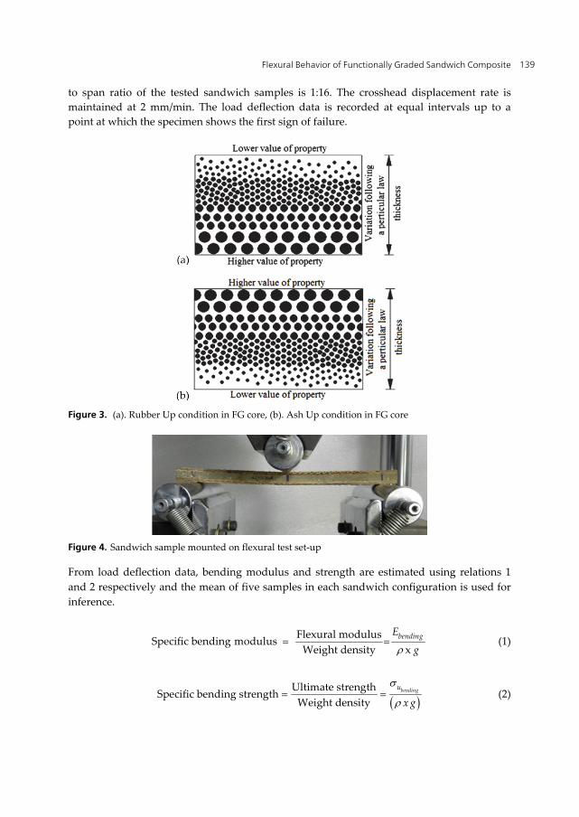
The mechanical testing of sandwich composites to obtain parameters such as strength, stiffness etc. is a time consuming and often difficult process. It is, however, an essential process, and can be somewhat simplified by the testing of simple structures such as flat coupons. The data obtained from these tests can then be directly related with varying degrees of simplicity and accuracy to any structural shape. The test methods outlined in this section merely represent a small selection available to the composites scientist. Various FG sandwiches fabricated are characterized for three point bending condition. Influence of rubber up (rubber rich region towards the top) and ash up (ash rich region below the loading point) configurations are critically analyzed. Expected gradation in FG cores is presented in Figure 3 (rubber up and ash up).
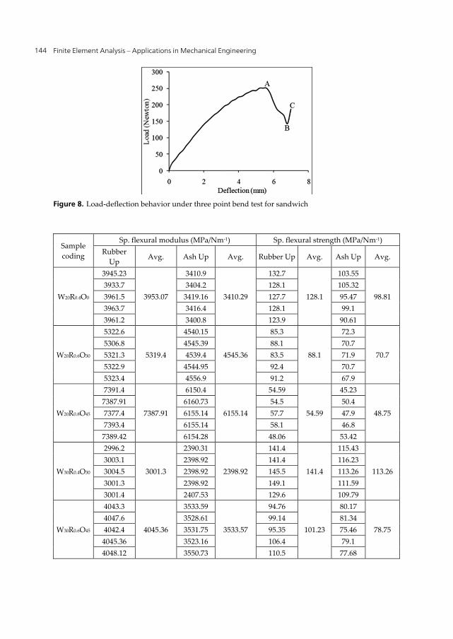
The three point bending test is carried out in accordance with ASTM C 393 [42] using Instron universal testing machine of model 4206 with loading capacity ranging from 0.1 N to 150 kN. Figure 4 shows the sandwich sample mounted on flexural test set-up. The thickness
Flexural Behavior of Functionally Graded Sandwich Composite 139
to span ratio of the tested sandwich samples is 1:16. The crosshead displacement rate is maintained at 2 mm/min. The load deflection data is recorded at equal intervals up to a point at which the specimen shows the first sign of failure.
Figure 3. (a). Rubber Up condition in FG core, (b). Ash Up condition in FG core
Figure 4. Sandwich sample mounted on flexural test set-up
From load deflection data, bending modulus and strength are estimated using relations 1 and 2 respectively and the mean of five samples in each sandwich configuration is used for inference.
Flexural modulusSpecific bending modulus Weight density x
bendingEg
(1)
Ultimate strengthSpecific bending strengthWeight density
bendingu
x g
(2)

Finite Element Analysis – Applications in Mechanical Engineering 140
where 3
6bendingu
MB H
and 4
FLM
5.1. Details of finite element modelling
As outlined earlier, FE model helps to model the constituents of the FG composites and their sandwiches to study the interactions of these in load transfer and mechanisms influencing their failure. To understand and predict the effect of material as well as geometrical parameters on the mechanical behavior of FG fly ash filled rubber composites and their sandwiches finite element analysis can be a very effective technique. Towards this, a simple disctretized model is built in the software ANSYS® representing FG composites with properties varying from top layer to bottom representing gradation.
Static analysis is performed using FEM software ANSYS 5.4. In this analysis a two dimensional model of a FG system is constructed and meshed with 4-node PLANE42 element. Three different mesh sizes are tested with 4-node elements to check the convergence of the model, based on which medium mesh size (element edge length is taken as 0.5) is selected. Number of nodes and elements used in the analysis are 800 and 5000 respectively.
Finite element values are compared with experimental ones for bending behavior of FG sandwich. At the contact surfaces of the layers and between layers and faces of sandwich glue conditions are applied to eliminate relative movement of layers with respect of each other. Furthermore, nodes are merged at the interface allowing proper coupling between layers and interfaces. Figure 5 shows finite element mesh with boundary conditions as a typical case considered for three point bending analysis. Skins are being represented by top and bottom portions of the structure whereas in between are the four layers having graded properties.
Figure 5. Finite element mesh with boundary condition for FG sandwich
While modeling gradation in ANSYS 5.4, the analogy of springs is used having differing stiffness (K1 < K2 < K3 < K4) from the top layer to bottom (Figure 6).
Sandwiches with FG core are modeled in FEA package ANSYS 5.4 [43] as emphasized before. Three different gradations of filler U (uniform), L (linear) and PL (piecewise linear) are considered during modeling of FG cores (Figure 7). Young’s modulus and density of FG cores are determined for different weight fractions of fly ash from constituent properties are provided as input to FEA (Table 8).

Flexural Behavior of Functionally Graded Sandwich Composite 141
Figure 6. Spring analogy for gradation in modulus of core material
Figure 7. FG rubber core configurations used in FEA
Fly ash distributions taken into account for uniform configuration are 20%, 30% and 40% through the thickness. For these weight fractions Young’s modulus is estimated using inverse rule of mixtures For skins, young’s modulus is estimated by preparing five tensile samples of jute/epoxy with orientations of 00/900, 300/600 and 450/450 which are subsequently tested as per ASTM D3039 [44] guidelines. Density of skins is determined experimentally using procedure outlined in ASTM D792 [45]. Table 8 presents properties of core and skin used in the FE analysis. Results of FE analysis are compared with experimental values.
FG Core
Element Wt. % of fly ash
Young’s modulus (GPa) Density (Kg/m3)
U L PL* U L PL*
20% 0.7575
0.65 (upper)
0.75 (middle)
0.88 (bottom)
0.65 (L1)
1168.4 1163.9 (L1)1167.5 (L2)1172.5 (L3)
1162.8 (L1)
2D Plane 42
0.71 (L2) 1165.2 (L2) 0.79 (L3) 1168.2 (L3)
0.88 (L4) 1173.5 (L4)

Finite Element Analysis – Applications in Mechanical Engineering 142
FG Core Element Wt. % of
fly ash Young’s modulus (GPa) Density (Kg/m3)
U L PL* U L PL*
30% 0.89
0.68 (upper)
0.865 (middle)
1.15 (bottom)
0.68 (L1)
1330.2 1324.5 (L1)1331.1 (L2)1336.9 (L3)
1323.9 (L1) 0.79 (L2) 1328.4 (L2) 0.94 (L3) 1334.6 (L3)
1.15 (L4) 1337.2 (L4)
40% 1.1
0.71 (upper)
1.015 (middle)
1.66 (bottom)
0.71 (L1)
1444.7 1435.2 (L1)1445.7 (L2)1452.6 (L3)
1434.9 (L1) 0.88 (L2) 1442.8 (L2) 1.15 (L3) 1450.6 (L3)
1.66 (L4) 1455.2 (L4)
Jute / Epoxy skin Orientation Ex (GPa) Ey (GPa) Density (Kg/m3)
00/900 3.25 2.5 1468 300/600 1.63 1.25 1451.2 450/450 2.29 1.77 1444.3
L-layer, *L1-top layer (rubber rich), L4-bottom layer (ash rich)
Table 8. Core and skin properties used in FEA
Bending tested samples are subjected to visual observation using regular photography technique for FG sandwich. These methods came in handy during the characterization of failures especially in impact failed samples.
6. Results and discussion
FG sandwiches are tested for Density, the results of which are presented in Table 9.
Sandwich code Trial-1 Trial-2 Trial-3 Trial-4 Trial-5 Density (Kg/m3)
W20R0.4O0 1325.6 1328.9 1329.4 1332.8 1330.8 1329.5 W20R0.6O30 1333.5 1334.8 1336.2 1336.4 1331.6 1334.5 W20R0.8O45 1342.8 1350.7 1348.6 1345.5 1348.9 1347.3 W30R0.4O30 1465.8 1464.6 1460.3 1462.1 1463.2 1463.2 W30R0.6O45 1435.2 1435.9 1431.9 1432.8 1433.7 1433.9 W30R0.8O0 1467.1 1466.9 1469.3 1470.5 1467.2 1468.2 W40R0.4O45 1547.6 1549.8 1551.7 1550.6 1548.8 1549.7 W40R0.6O0 1599.5 1598.8 1595.6 1594.4 1596.2 1596.9 W40R0.8O30 1564.1 1561.8 1562.4 1560.9 1563.8 1562.6
Table 9. Density results of FG sandwiches

Flexural Behavior of Functionally Graded Sandwich Composite 143
Experimental density values are subjected to statistical analysis (MINITAB 14) to propose regression equation which is presented in equation 3.
3Density Kg / m 1099 11.6 Fly ash weight %
29.7 C / H Ratio [0.459 Jute Orientation]
(3)
Equation 3 comes handy, which predicts density for large number of samples with varying combination of factors within the range of chosen levels without experimentation. Density increases with filler content as well as with C/H ratio (core to thickness ratio) being positive coefficients while shows a decreasing trend with increase in jute orientation. Obvious reason for this might be lower specific weight with increasing skin orientation.
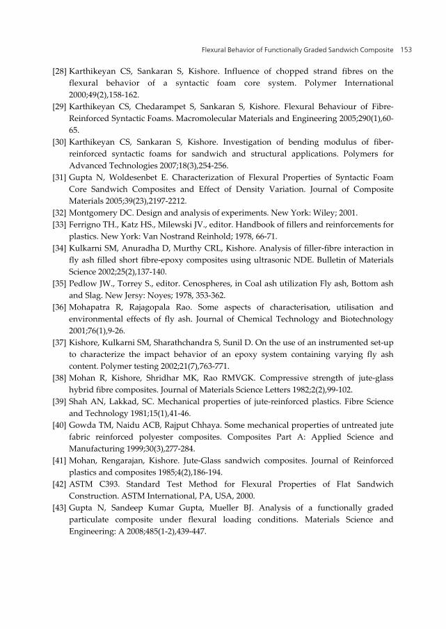
Three point bending behavior of a FG sandwich composite is investigated under flexural loading condition. Results are analyzed for specific modulus and specific bending strength. Load deflection data is traced all along the path. The load and corresponding deflection data is noted at equal intervals up to a maximum load at which the specimen shows the first sign of failure (point ‘A’). The load and deflections obtained during testing are plotted. A typical load deflection curve is shown in Figure 8.
Load-displacement consists of an initial linear part followed by a nonlinear portion (Figure 8). A nonlinear mechanics of materials analysis that accounts for the combined effect of the nonlinear behavior of the facings and core materials (material nonlinearity) and the large deflections of the beam (geometric nonlinearity) are observed. The nonlinear load-deflection behavior of the beams is attributed to the combined effect of material and geometric nonlinearity. The material nonlinearity of the sandwich beam is due to the nonlinear normal stress-strain behavior of the facing material and the FG core. For long beam spans, even though there is a geometric nonlinearity effect, the overall load-deflection curve of the beam does not deviate much from linearity.
For long beam spans the nonlinearity of the load-deflection curve is mainly due to the combined effect of the facings nonlinearity and the large deflections of the beam. Both effects, however, have a small contribution to the load-deflection behavior, which shows a small deviation from linearity. Some of the general observations made are listed below.
1. The load decreases sharply after the end of the elastic region due to failure initiation in sandwich composites (A to B).
2. All samples have shown small linear region (B to C) before skin failure in compressive side.
3. Variation in displacement value at which peak load is observed for various types of FG sandwiches is considerable.
4. The failure originates on the tensile side.
6.1. Specific bending modulus
From load deflection data the average specific modulus and strength for five samples (Table 10) are estimated using equations 1 and 2.
Finite Element Analysis – Applications in Mechanical Engineering 144
Figure 8. Load-deflection behavior under three point bend test for sandwich
Sample coding
Sp. flexural modulus (MPa/Nm-1) Sp. flexural strength (MPa/Nm-1) Rubber
Up Avg. Ash Up Avg. Rubber Up Avg. Ash Up Avg.
W20R0.4O0
3945.23
3953.07
3410.9
3410.29
132.7
128.1
103.55
98.81 3933.7 3404.2 128.1 105.32 3961.5 3419.16 127.7 95.47 3963.7 3416.4 128.1 99.1 3961.2 3400.8 123.9 90.61
W20R0.6O30
5322.6
5319.4
4540.15
4545.36
85.3
88.1
72.3
70.7 5306.8 4545.39 88.1 70.7 5321.3 4539.4 83.5 71.9 5322.9 4544.95 92.4 70.7 5323.4 4556.9 91.2 67.9
W20R0.8O45
7391.4
7387.91
6150.4
6155.14
54.59
54.59
45.23
48.75 7387.91 6160.73 54.5 50.4 7377.4 6155.14 57.7 47.9 7393.4 6155.14 58.1 46.8 7389.42 6154.28 48.06 53.42
W30R0.4O30
2996.2
3001.3
2390.31
2398.92
141.4
141.4
115.43
113.26 3003.1 2398.92 141.4 116.23 3004.5 2398.92 145.5 113.26 3001.3 2398.92 149.1 111.59 3001.4 2407.53 129.6 109.79
W30R0.6O45
4043.3
4045.36
3533.59
3533.57
94.76
101.23
80.17
78.75 4047.6 3528.61 99.14 81.34 4042.4 3531.75 95.35 75.46 4045.36 3523.16 106.4 79.1 4048.12 3550.73 110.5 77.68

Flexural Behavior of Functionally Graded Sandwich Composite 145
Sample coding
Sp. flexural modulus (MPa/Nm-1) Sp. flexural strength (MPa/Nm-1) Rubber
Up Avg. Ash Up Avg. Rubber Up Avg. Ash Up Avg.
W30R0.8O0
6559.3
6562.65
6018.2
6018.2
148.7
153.1
120.1
119.3 6562.8 6018.2 149.2 121.3 6570.4 6018.2 157.3 118.3 6560.55 6020.9 151.2 121.54 6560.21 6015.5 159.1 115.26
W40R0.4O45
2134.3
2138.92
1702
1692.71
149.3
151.4
110.34
117.17 2138.69 1692.67 148.7 121.56 2141.92 1688.2 152.4 117.17 2139.26 1690.4 159.3 120.23 2140.42 1690.3 147.3 116.55
W40R0.6O0
4372.5
4365.98
4060.12
4065.98
188.98
192.21
159.21
154.45 4370.28 4068.63 193.5 155.29 4365.39 4065.98 199.7 152.8 4360.87 4059.3 191.49 155.7 4360.86 4075.86 187.38 149.25
W40R0.8O30
6515.5
6518.2
6050.3
6062.65
155.23
159.53
121.44
125.45 6520.7 6070.4 151.8 123.3 6521.4 6060.9 161.32 127.56 6518.2 6058.5 164.2 128.9 6515.2 6073.15 165.1 126.05
Table 10. Specific bending modulus and strength for FG sandwich
It can be clearly seen from the table that, rubber up configuration registered higher results compared to ash up condition for both the properties in the range of 7 to 30%. Constrained straining and resisting forces set up in the FG core might be the reasons for such an observation in bending test as depicted in Figure 9.
Figure 9. Loads acting on FG sandwich in bending test

Finite Element Analysis – Applications in Mechanical Engineering 146
Rubber up condition of FG core in sandwich represents ash rich region on tensile side. Crack initiation is observed to be from tensile region to compressive region in pre sent loading case. In rubber up condition, as stiffer zone is near tensile region, sandwich can take up higher loads resulting in better performance compared to homogenous cores and ash up condition in FG core. Thereby, such sandwiches are excellent examples of optimized designs.
Developed FG sandwiches can be used in practical cases wherein structures are continuously subjected to bending loads. Depending upon whether load is acting downwards or upwards sandwiches can be suitable placed with either rubber up or ash up configuration as regards to FG cores.
Figure 10 shows the signal to noise (SN) response plot for specific bending modulus with respect to the parameters under study. Response of SN ratio in Specific bending modulus for Rubber Up condition is presented in Table 11.
Figure 10. Variation of SN ratio in specific bending modulus (Rubber Up)
Fly ash weight % C/H ratio Orientation Level 1 74.61 69.36 73.69 Level 2 72.68 73.15 73.45 Level 3 71.90 76.66 72.04 Effect 2.71 7.30 1.66 Rank 2 1 3
Table 11. SN ratio table for specific bending modulus (Rubber Up)
From the data analysis, vide response Table 11, it is seen that C/H ratio and fly ash % exhibit greater influence compared to the orientation. It is further observed from the Table and Figure 10 that samples with fly ash content of 20%, C/H of 0.8 and an orientation of 00/900 possess highest specific bending modulus. This could be due to higher C/H ratio implying larger rubber rich region imparting higher modulus to sandwich system.

Flexural Behavior of Functionally Graded Sandwich Composite 147
6.2. Specific bending strength
Results of specific bending strength from Table 10 are statistically analyzed and are used to rank the variables as presented in Table 12.
Fly ash weight % C/H ratio Orientation Level 1 38.6 42.92 43.84 Level 2 42.27 41.56 41.99 Level 3 44.44 40.83 39.48 Effect 5.85 2.09 4.36 Rank 1 3 2
Table 12. SN ratio table for specific bending strength (Rubber Up)
From SN response Table, it can be seen that specific bending strength behavior is prominently governed by fly ash weight % followed by orientation and C/H ratio. Figure 11 presents SN plot for specific bending strength incase of rubber up condition.
Figure 11. Plot of SN ratio in specific bending strength (Rubber Up)
From SN response plot shown in Figure 11, the best combination for specific strength is a sample with fly ash content of 40%, C/H of 0.4 and orientation of 00/900. Reasons for this could be stiffening effect due to high modulus filler and larger skin-epoxy component for lower C/H ratios. Similar results are observed for ash up configuration. Even though W20R0.8O45 and W40R0.6O0 are showing higher values (Table 10) for modulus and strength respectively, inference on basis of these will not lead to an appropriate conclusion. The reason being these values are merely based on average of means. Inference on the grounds of SN analysis leads to a meaningful conclusion as it takes means and data spread into account. By the SN ratio analysis the best sandwich configurations are W20R0.8O0 and W40R0.4O0 for specific modulus and strength respectively. Similar observation is noted for ash

Finite Element Analysis – Applications in Mechanical Engineering 148
up configuration. Regression equation is proposed based on the experimental data for specific bending properties are presented in equations 4-7.
Specific Bending Modulus Rubber Up 1151 – 60.6 Weight % of Fly ash
480 C / H Ratio – 8.38 Jute Orientation
(4)
Specific Bending Strength Rubber Up 70.4 3.87 Weight % of Fly ash
– 44.7 C / H Ratio – 1.19 Jute Orientation
(5)
Specific Bending Modulus Ash Up 342 – 38.2 Weight % of Fly ash
8945 C / H Ratio – 14.2 Jute Orientation
(6)
Specific Bending Strength Ash Up 54.2 2.98 Weight % of Fly ash
– 29.8 C / H Ratio – 0.912 Jute Orientation
(7)
6.3. Finite element analysis
Specific bending strength is estimated by simulating the sample and loading (Gupta et al. 2008) in FEA. Figure 12 represents the plot for bending stress in the sample for one typical loading case.
Figure 12. Bending stress in x-direction for typical case in FG sandwich

Flexural Behavior of Functionally Graded Sandwich Composite 149
The breaking load taken from experiment is applied on FE model. For this applied load, maximum stress (von misses criteria) is recorded and finally specific strength is determined by taking the ratio of maximum stress to the weight of sample. The specific strength values obtained from FEA for three variations in gradation (Uniform-U, Linear-L and Piecewise linear-PL) and with experimental approach is presented in Table 13.
Sandwich configuration
FEA Experimental % Error with PL
U L PL W20R0.4O0 115.4 119.6 132.75 128.1 3.50 W20R0.6O30 78.2 81.5 92.58 88.1 4.84 W20R0.8O45 46.9 48.9 58.58 54.59 6.81 W30R0.4O30 125.1 130.2 147.34 141.4 4.03 W30R0.6O45 84.4 88.8 110.38 101.23 8.29 W30R0.8O0 129.7 137.6 160.88 153.1 4.84 W40R0.4O45 126.6 131.3 169.11 151.4 10.47 W40R0.6O0 175.2 179.5 201.42 192.21 4.57 W40R0.8O30 140.2 145.6 165.7 159.53 3.72
Table 13. Specific bending strength (MPa/Nm-1) results for sandwich
It is significant to note that the experimental results for specific bending strength match well with FEA values especially for the ones with PL gradation. It is observed that bending strength obtained from FEA is slightly higher than experimental values. This could be due to inability of modeling inhomogenities creeping in during the processing of samples which may result in lowering specific strength.
6.4. Discussion on fractured samples
Within the elastic region of the load-displacement curve (Figure 8), where no damage is induced, the responses of all specimens to the applied loads are quite similar. This is visible in the form of nearly constant slope in the elastic region of the load-displacement curves. It is observed that the failure starts in the form of crack origination on the tensile side of the specimen as displacement increases. On further loading, the skin of the sandwich composite that is on the tensile side tends to fracture, causing the final failure of the specimen. However, it is not significant enough to lead to the final failure of the specimen. It is observed that the entire specimen fractures at a much later instant of skin fracture. Appearance of small linear region (B to C in Figure 8) at the end in the load-displacement curves is due to stiffening of FG core before final failure. During the loading process, deformation also takes place in the compression side of the specimen. Cracks initiate from the tensile side and propagate to the compressive side within the core in all sandwiches.
It is worth discussing the mode of failure. Sandwich samples tested under bending did not display the distinct separation into pieces at failure. The FG core being compliant is

Finite Element Analysis – Applications in Mechanical Engineering 150
observed to be successfully absorbing media. Basically two types of failure mechanisms observed are skin cracking and delamination between skins and core. Figure 13 shows the failed sandwich specimens with their failure modes.
Figure 13. Sandwich failure modes under three point bending loads
The sandwich beams failed at the center of the two supporting rollers. In this portion of the beam, the shear force is zero and only the pure bending exists. Thus, the sandwich samples are capable of resisting higher bending moment. As the load on the specimen is increased, failures first start under the loads in tensile region and then they propagate towards the compressive zone through compliant FG core. All the samples failed under skin tension or compression and skin - core debonding. The sandwiches with higher C/H ratio have shown skin - core debonding. FG core takes up most of the load applied for higher C/H ratios (lesser skin thickness). Since core is made up of rubber composite being compliant in nature, relative movements are set up with respect to skin resulting in inter laminar shear stresses. As magnitude of these stresses crosses the adhesive strength delamination creeps in. Some sandwich samples are seen to be intact even after the first sign of failure. These samples exhibited a spring back effect. Samples bearing lower C/H ratio have failed mainly because of skin cracking along the jute orientation. Few samples failed due to shearing at skin-core interface displayed step formation.
7. Conclusions
This section highlights the significant conclusions drawn from the results presented earlier. Major inferences from both experimental and finite element investigations are discussed below.
Density of FG sandwiches increases with filler content and C/H ratio while decreases with jute orientation. An experimental investigation of sandwiches under bending loads for specific modulus and specific strength shows that C/H ratio and fly ash weight fraction are the influential factors respectively. Specific bending modulus in both cases (i.e. rubber up and ash up) the sample W20R0.8O0 registered the higher value while W40R0.4O0 shows

Flexural Behavior of Functionally Graded Sandwich Composite 151
higher value of specific strength. Rubber up configuration registered higher results compared to ash up condition for modulus and strength. The ash up condition recorded about 30% increase in strength. Increasing fly ash weight fraction rendered an increase in bending strength of about 29% for rubber up condition. Specific strength values estimated from FEA for bending loads match well with experimental results especially for piecewise gradation.
Author details
Mrityunjay R. Doddamani* and Satyabodh M Kulkarni Mechanical Engineering, National Institute of Technology Karnataka, Surathkal, India
8. References
[1] Nicoleta Alina Apetre. Sandwich Panels with Functionally Graded Core. PhD thesis. Graduate school of the university of Florida; 2005.
[2] Vinson J. The Behavior of Sandwich Structures of Isotropic and Composite Materials. Pennsylvania: Technomic; 1999.
[3] Gdoutos EE, Daniel IM. Failure modes of composite sandwich Beams. Journal of Theoretical and Applied Mechanics 2008;35(1-3),105-118.
[4] Venkata Dinesh Muthyala. Composite sandwich structure with grid stiffened core. Master thesis. Graduate Faculty of the State University and Agricultural and Mechanical College, Louisiana, 2007.
[5] Zenkert D. Handbook of Sandwich Construction. London: EMAS, Chameleon Press; 1997.
[6] Abrate S. Impact on Composite Structures. Cambridge: Cambridge University Press; 1998.
[7] Paulino GH, Jin ZH. Correspondence Principle in Viscoelastic Functionally Graded Materials. Journal of Applied Mechanics 2001;68(1),129-132.
[8] Koizumi M. Concept of FGM. Ceramic Transactions 1993;34,3-10. [9] Suresh S, Mortensen A. Fundamentals of Functionally Graded Materials. London:
Institute of Materials; 1998. [10] Miyamoto Y, Kaysser WA, Rabin BH, Kawasaki A, Ford RG. Functionally Graded
Materials: Design, Processing and Applications. Dordrecht: Kluwer Academic; 1999.
[11] Cannillo V, Manfredini T, Siligardi C, Sola A. Preparation and experimental characterization of glass–alumina functionally graded materials. Journal of the European ceramic society 2006;26(6),993-1001.
[12] Al-Ajmi MA, Alhazza KA. 5th International Conference on Composite Science and Technology, ICCST/5 2005: conference proceeding. Vibration and damping analysis of
* Corresponding Author

Finite Element Analysis – Applications in Mechanical Engineering 152
sandwich beams with functionally graded viscoelastic core. Sharjah, United Arab Emirates, 125 - 128.
[13] Parameswaran V, Shukla A. Processing and Characterization of a Model Functionally Gradient Material. Journal of Materials Science 2000;35(1),21-29.
[14] Venkataraman S, Sankar BV. 42nd AIAA/ASME/ASCE/AHS/ASC Structures, Structural Dynamics and Materials Conference 2001: conference proceeding. Analysis of sandwich beams with functionally graded core. AIAA-2001-1281, Seattle, Washington.
[15] Kirigulige MS, Kitey R, Tippur HV. Dynamic fracture behaviour of model sandwich structures with functionally graded core: a feasibility study. Composites Science and Technology 2005;65(7-8),1052-1068.
[16] Pollien A, Conde Y, Pambaguian L, Mortensen A. Graded open-cell aluminium foam core sandwich beams. Materials Science and Engineering: A 2005;404(1-2),9-18.
[17] Gupta N. A functionally graded syntactic foam material for high energy absorption under compression. Materials Letters 2007;61(4-5),979-982.
[18] Krajcinovic D. Sandwich Beam Analysis. Journal of Applied Mechanics 1971;38(1),773-778.
[19] Krajcinovic D. Sandwich Beams with Arbitrary Boundary Conditions. Journal of Applied Mechanics 1975;42(1),873-880.
[20] DiTaranto RA. Static Analysis of a Laminated Beam. Journal of Engineering for Industry 1973;95(2),755-761.
[21] Johnson AF, Sims GD. Mechanical Properties and Design of Sandwich Materials. Composites 1986;17(4),321-328.
[22] Teti R, Caprino G. First International Conference on Sandwich Construction 1989: conference proceeding. Mechanical Behavior of Structural Sandwiches. Stockholm, Sweden, 53-67.
[23] Lingaiah K, Suryanarayana BG. Strength and Stiffness of Sandwich Beams in Bending. Experimental Mechanics 1991;31(1),1-7.
[24] Gupta N, Woldesenbet E. Microscopic Studies of Syntactic Foams Tested Under Three-Point Bending Conditions. American Society of Mechanical Engineers 2002;1,147-152.
[25] Maharsia R, Gupta N, Jerro HD. Investigation of flexural strength properties of rubber and nanoclay reinforced hybrid syntactic foams. Materials Science and Engineering: A 2006;417(1-2),249-258.
[26] Kishore, Ravi, Sankaran S. Short-Beam Three-Point Bend Test Study in Syntactic Foam. Part III: Effects of Interface Modification on Strength and Fractographic Features. Journal of Applied Polymer Science 2005;98(2),687-693.
[27] Avila AF. Failure mode investigation of sandwich beams with functionally graded core. Composite Structures 2007;81(3),323-330.
Flexural Behavior of Functionally Graded Sandwich Composite 153
[28] Karthikeyan CS, Sankaran S, Kishore. Influence of chopped strand fibres on the flexural behavior of a syntactic foam core system. Polymer International 2000;49(2),158-162.
[29] Karthikeyan CS, Chedarampet S, Sankaran S, Kishore. Flexural Behaviour of Fibre-Reinforced Syntactic Foams. Macromolecular Materials and Engineering 2005;290(1),60-65.
[30] Karthikeyan CS, Sankaran S, Kishore. Investigation of bending modulus of fiber-reinforced syntactic foams for sandwich and structural applications. Polymers for Advanced Technologies 2007;18(3),254-256.
[31] Gupta N, Woldesenbet E. Characterization of Flexural Properties of Syntactic Foam Core Sandwich Composites and Effect of Density Variation. Journal of Composite Materials 2005;39(23),2197-2212.
[32] Montgomery DC. Design and analysis of experiments. New York: Wiley; 2001. [33] Ferrigno TH., Katz HS., Milewski JV., editor. Handbook of fillers and reinforcements for
plastics. New York: Van Nostrand Reinhold; 1978, 66-71. [34] Kulkarni SM, Anuradha D, Murthy CRL, Kishore. Analysis of filler-fibre interaction in
fly ash filled short fibre-epoxy composites using ultrasonic NDE. Bulletin of Materials Science 2002;25(2),137-140.
[35] Pedlow JW., Torrey S., editor. Cenospheres, in Coal ash utilization Fly ash, Bottom ash and Slag. New Jersy: Noyes; 1978, 353-362.
[36] Mohapatra R, Rajagopala Rao. Some aspects of characterisation, utilisation and environmental effects of fly ash. Journal of Chemical Technology and Biotechnology 2001;76(1),9-26.
[37] Kishore, Kulkarni SM, Sharathchandra S, Sunil D. On the use of an instrumented set-up to characterize the impact behavior of an epoxy system containing varying fly ash content. Polymer testing 2002;21(7),763-771.
[38] Mohan R, Kishore, Shridhar MK, Rao RMVGK. Compressive strength of jute-glass hybrid fibre composites. Journal of Materials Science Letters 1982;2(2),99-102.
[39] Shah AN, Lakkad, SC. Mechanical properties of jute-reinforced plastics. Fibre Science and Technology 1981;15(1),41-46.
[40] Gowda TM, Naidu ACB, Rajput Chhaya. Some mechanical properties of untreated jute fabric reinforced polyester composites. Composites Part A: Applied Science and Manufacturing 1999;30(3),277-284.
[41] Mohan, Rengarajan, Kishore. Jute-Glass sandwich composites. Journal of Reinforced plastics and composites 1985;4(2),186-194.
[42] ASTM C393. Standard Test Method for Flexural Properties of Flat Sandwich Construction. ASTM International, PA, USA, 2000.
[43] Gupta N, Sandeep Kumar Gupta, Mueller BJ. Analysis of a functionally graded particulate composite under flexural loading conditions. Materials Science and Engineering: A 2008;485(1-2),439-447.

Finite Element Analysis – Applications in Mechanical Engineering 154
[44] ASTM D3039. Standard Test Method for Tensile properties of polymer matrix composite materials. ASTM International, PA, USA, 2008.
[45] ASTM D792. Standard test methods for density and specific gravity (Relative density) of plastics by displacement. ASTM International, PA, USA, 2008.