flexible platform component design under...
TRANSCRIPT

J Intell Manuf (2007) 18:115–126DOI 10.1007/s10845-007-0008-x
Flexible platform component design under uncertainty
Eun Suk Suh · Olivier de Weck · Il Yong Kim ·David Chang
Received: August 2005 / Accepted: February 2006 / Published online: April 2007© Springer Science+Business Media, LLC 2007
Abstract Incorporating flexibility into product plat-forms allows manufacturers to respond to changing mar-ket needs with a minimal increase in product familycomplexity and investment cost. To successfully designa flexible product platform, proper design of flexibleplatform components is critical. These components canbe described as “cousin” parts as they are neither com-pletely unique nor completely common among variants.In this paper, a multidisciplinary process for design-ing flexible product platform components is introduced,assuming the platform component is decided a priori.The design process starts with identification of uncer-tainties and generation of multiple design alternativesfor embedding flexibility into the component. Designalternatives are then optimized for minimum cost, whilesatisfying the component performance requirements.The flexible designs are then evaluated for economicprofitability under identified uncertainty, using MonteCarlo simulation. At the end, the most profitable flexible
D. Chang was retired from General Motors R & D
E. S. Suh · O. de Weck (B)Engineering Systems Division, Massachusetts Institute ofTechnology, Cambridge, MA 02139, USAe-mail: [email protected]
E. S. Suhe-mail: [email protected]
I. Y. KimDepartment of Mechanical and Materials Engineering,Queens University, Kingston, ON, Canada, K7L 3N6e-mail: [email protected]
D. ChangGeneral Motors R & D, Warren, MI 48090, USAe-mail: [email protected]
component design is selected. The proposed design pro-cess is demonstrated through a case study, in whichdifferent flexible designs are generated and optimizedfor an automotive floor pan, an essential element ofmost vehicle product platforms. Results suggest that theway in which the flexibility is incorporated in the com-ponent, production volume trends, and the degree ofbuilt-in flexibility are important factors to consider whendesigning flexible product platforms.
Keywords Product platform · Flexibility · Uncertainty
Nomenclaturec Total unit cost of the componentca Unit assembly cost of a componentcf Unit fabrication cost of a componentC Total variable cost for a design alternativeCF Cash flowDh Historical demandDo Initial demandE[D] Expected demandE[NPV] Expected net present valueF Set of economic variablesJ Set of performance variableskL Total line investment costkT Total tooling investment costK Total capital investment costL Length of the floor panM Mass of the floor panNPV Net present valueNS Number of simulation runsp Number of uncertain parametersq Number of component variantsr Discount rateT Lifetime of the product platform

116 J Intell Manuf (2007) 18:115–126
TF Total number of future time periodsTH Total number of historical time periodsu Individual uncertaintyU Set of uncertaintiesv Individual design alternativeV Set of design alternativesw Number of welding connectionsxL Geometric design vector for long floor panxs Geometric design vector for short floor panY Total number of design alternativesα Drift coefficientε Random variable ∼N(0,1) normally distributedδ Bending stiffnessσ Volatility coefficientτ Torsional stiffness
Introduction
In the age of mass customization (Pine, 1993), custom-ers demand more personalized products, creating a needfor large product variety. However, increasing varietyin the product family can lead to additional productcomplexity and higher development costs. In order toreduce the product complexity and development costswhile offering more product variants, many innovativeproduct design and manufacturing strategies have beenproposed and implemented.
A widely implemented strategy is the product plat-form strategy, documented by Meyer & Lehnerd (1997).According to the authors mentioned previously, a prod-uct platform is “the set of common components, mod-ules, or parts from which a stream of derivative productscan be efficiently developed and launched.” A bene-fit of the product platform strategy is pointed out byRobertson and Ulrich (1998), who state that, “by shar-ing components and production processes across a plat-form of products, companies can develop differentiatedproducts efficiently, increase the flexibility and respon-siveness of their manufacturing processes, and take mar-ket share away from competitors that develop only oneproduct at a time.” In industry, the product platformconcept has been implemented in many products includ-ing portable Walkman® (Sanderson & Uzumeri, 1997),power tools (Meyer & Lehnerd, 1997) and automobiles(Bremmer, 1999). Active research for productplatform design and optimization has been carried outduring the last decade. Research topics include plat-form design process development (Fellini et al., 2002;Simpson, Maier, & Mistree, 2001), optimum platformcomponent selection (Martin & Ishii, 2002; Nelson II,Parkinson, & Papalambros, 2001), and platform portfo-lio optimization and valuation (de Weck, Suh, & Chang,2003; Kidd, 1998), to name a few.
Even though the product platform strategy has manyadvantages, it can also have disadvantages. Increasingthe degree of commonality in the product family canlead to loss of performance competitiveness. Also, shar-ing common components between high end productsand low end products can lead to cannibalization (Cook,1997), where brands of the same manufacturer competewith each other, causing loss of sales for one brand.Finally, the platform strategy can deter the implementa-tion of new technological innovations, since investmentcosts and switchover costs to implement such technicalinnovations can be very high.
A good systematic solution to overcome disadvan-tages is to embed flexibility into the product platform.The word flexibility is defined as “the ease of chang-ing the system’s requirements with a relatively smallincrease in complexity (and rework)” (ESD Commit-tee, 2002). By building flexibility into the product plat-form itself, the manufacturer can produce variants fromthe platform with sufficient distinctiveness, and imple-ment new technological innovations to the platform withreduced investment in facilities, tooling, and labor train-ing. A flexible platform can also respond to changingmarket needs quickly and efficiently.
However, embedding flexibility into all platform ele-ments (components, interfaces, processes, etc.) can bevery costly and inefficient. It would be ideal to identifycritical elements of the platform, the ones that are highlysensitive to product performance attributes, and addflexibility to those elements. Flexibility can be embed-ded into various levels of manufacturing from a sin-gle machine to the entire manufacturing plant (Sethi &Sethi, 1990). Flexibility can also be added into physi-cal components directly. Finally, the managerial flexi-bility to exercise “platform flexibility” can be analyzedusing Real Options theory (Trigeorgis, 1996), which isan extension of classic financial option theory developedby Black and Scholes (1973).
In this paper, a multidisciplinary design process forflexible platform components is introduced. The designprocess takes future uncertainties into account. Severalresearch papers have been published in the area ofdesign under uncertainty. Li and Azarm (2000, 2002)proposed a framework for product design selection andproduct line selection under uncertainty and competi-tion. Georgiopoulos, Fellini, Sasena, and Papalambros(2002) proposed a process where a product portfolio isoptimized for maximum economic benefits subject toperformance and production capacity constraints, whileaccounting for future demand uncertainty. However,this article focuses on the topic of flexible componentdesign under future uncertainties. The main contribu-tion of this paper is to develop an integrated design

J Intell Manuf (2007) 18:115–126 117
Fig. 1 Proposed designprocess
Step II Flexible Component Design
Alternative Generation
Step III Design Alternative Optimization
SelectBest
Design
Step I Uncertainty
Identification
Step IV Uncertainty
Analysis
Demand Change vs. Option NPV
$0
$5,000,000
$10,000,000
$15,000,000
$20,000,000
$25,000,000
1/4 1.5/3.5 2/3 2.5/2.5 3/2 3.5/1.5 4/1
Demand Ratio (L/S)
To
tal N
PV
($)
Opt1 NPV Opt2 NPV Opt3 NPV Opt4 NPV
Demand vs. Time
0
50000
100000
150000
200000
250000
19 17 25 33 41 49 57 65 73 81 89 97
Time
Dem
and
(U
nit
s)
E[Dt]
GBM Dt
FutureDemand
DesignChange
Demand vs. Time
0
50000
100000
150000
200000
250000
19 17 25 33 41 49 57 65 73 81 89 97
Time
Dem
and
(U
nit
s)
E[Dt]
GBM Dt
Design I
Design II
.
.
Design Y
Performance Evaluation
EconomicOptimization
UncertaintyAnalysis
process for embedding flexibility into identifiedplatform components using multidisciplinary designoptimization and uncertainty analysis. Subsequentsections outline the proposed design process and dem-onstrate the process through a case study, in which flex-ible design alternatives of an automobile floor pan aregenerated, economically optimized, and analyzed underfuture demand and specification uncertainty.
Design process overview
Figure 1 shows a general overview of the design processfor flexible product platform components.
First, critical uncertainties for a target component areidentified. Second, several flexible component designalternatives are generated. Next, each flexible design isoptimized economically, while satisfying the componentperformance requirements. Optimized designs are thenevaluated in terms of long term economic gain by calcu-lating the total expected cost expenditure over the life-time of component production—expressed in terms ofexpected Net Present Value (E[NPV])—accounting forfuture uncertainties. A Monte Carlo simulation is usedto evaluate the E[NPV] over the total product platformlifetime. The mathematical formulation for each step isdiscussed below.
Uncertainty identification (Step I)
Define a set of critical uncertain parameters U.
U =[u1, u2, . . . , up
](1)
where u is one of p individual uncertainties identifiedfor the selected product platform component. Possi-ble uncertainties for platform components are futuredemand and design specification changes for particularplatform component variants.
Flexible component design alternative generation(Step II)
Define a set of component design alternatives V,consists of Y alternative designs.
V =[v1, v2, . . . vY
](2)
where
vv = [Jv, Fv] ; v = 1 . . . Y. (3)
Jv is a set of functional requirements and Fv is a set ofeconomic requirements for a component design alterna-tive. Functional requirements in Jv can vary for differenttypes of components, but economic requirements in Fv
are mostly the same for all component types. The set Fv
is defined as
Fv = [cv
i , Kv] ; i = 1 . . . q, v = 1 . . . Y (4)
where cvi is the unit cost of the ith component for q vari-
ants and Kv is the total product family investment costin each design alternative.
Design alternative optimization (Step III)
Each design in the flexible component design alternativeset V is optimized for minimum economic cost, while theset of functional requirements Jv must be satisfied.
Minimize Fv(xv)
Subject to h(xv) = 0g(xv) ≤ 0
(5)
xv is a set of component design variables and h(xv), g(xv)
are equality and inequality constraints Jv must satisfy.
Uncertainty analysis (Step IV)
Once all design alternatives in V are optimized, they areeconomically evaluated, under uncertainty, to determine

118 J Intell Manuf (2007) 18:115–126
the lifetime cost expenditure expressed in terms ofexpected Net Present Value (E[NPV]):
E[NPV]v=f (Fv(xv), U). (6)
Comparing E[NPV] of all flexible design alternatives inthe set V, the best design is selected.
The proposed design process is demonstrated throughthe case study of a vehicle floor pan, an important vehicleplatform component that requires dimensional flexibil-ity to accommodate a vehicle family with two differentwheelbase configurations.
Case study: automotive floor pan
Overview
A major automotive manufacturer is developing a newvehicle platform for its family of vehicles. Several criti-cal platform decisions are made a priori. The proposedvehicle platform strategy is to share a common under-body structure, which consists of common front and rearcompartments, and the flexible floor pan, a part of thevehicle platform. The floor pan is an important compo-nent that connects the front compartment and the rearcompartment of the automotive underbody structure.The width of the common underbody is fixed and is thesame for all vehicles, and the only dimensional variationis vehicle length, determined by the vehicle wheelbase.The wheelbase is adjusted by embedding dimensionalflexibility into the floor pan. It was decided that onlytwo variants of the floor pan (long and short) will beproduced for this platform at any given time since vehi-cles from this platform will be either long wheelbase orshort wheelbase vehicles. Figure 2 shows a CAD repre-sentation of the underbody structure.
All floor pans are to be fabricated from steel usingtransfer press technology. The objective is to create themost cost efficient flexible design to achieve dimensionalflexibility in vehicle length by adding geometric flexibil-ity into the floor pan.
Long Vehicles (Long Wheelbase)
Common Vehicle Underbody
Flexible Floor Pan
Short Vehicles (Short Wheelbase)
Fig. 2 Vehicle underbody structure
First, critical uncertainties related to the floor panare identified. Second, flexible design alternatives aregenerated. For each flexible floor pan design, optimi-zation is performed to minimize the mass of the floorpan, which in turn, minimizes the investment cost andvariable cost, while satisfying all structural performancerequirements. Once unit costs of the floor pan (c) and thetotal investment costs (K) are calculated, total expectedlifetime cost expenditure, expressed in terms of NetPresent Value (E[NPV]), is calculated using c and Kduring the uncertainty analysis. Comparing E[NPV] foreach flexible design, the best design is selected.
Uncertainty identification (Step I)
The first step is to identify future uncertainties relatedto the component. In this case study, two critical uncer-tainties are identified. They are future demand for longand short floor pans, and potential future changes in thefloor pan length itself, see Eq. (7):
U = [u1, u2]
u1 = [DS, DL]u2 = [LS, LL] .
(7)
Future demand for long and short floor pans is deter-mined by aggregating future demand for vehicles thatuse short and long floor pans. In addition, floor pans’geometric specification during the lifetime of the plat-form can be uncertain. In this study, the floor pan lengthsfor both long and short floor pans are treated as uncer-tain. Traditionally, one assumes that platform specifica-tions will not change over time. However, sinceplatforms are usually long-lived compared to the vari-ants that are derived from them, there is a need forflexibility in order to accommodate new variants overtime that did not exist when the platform was initiallycreated. This need for flexibility flows down to individ-ual components of the platform such as the floor panexamined here.
Flexible component design generation (Step II)
The second step is to generate flexible design alterna-tives for embedding dimensional flexibility into the floorpan. After considering platform constraints and otherdesign criteria, four design alternatives are generatedand shown in Fig. 3.
The first alternative is a customized design, where twoseparate floor pans are designed for short and long vari-ants. Floor pans are fabricated using separate stampingdies and tools, requiring separate investments for floorpans of different length. This is the baseline design withno geometric flexibility embedded into the floor panitself.

J Intell Manuf (2007) 18:115–126 119
I: CustomizedI: Customized II: BottomII: Bottom--UpUp
III: TopIII: Top--DownDown IV: UnbiasedIV: Unbiased
Small Large
Fig. 3 Proposed flexible floor pan designs
For the second design, called “bottom-up” design,the main floor pan is designed to fit the short floor panlength specification. To satisfy the long floor pan lengthrequirement, an extension piece is spot welded to themain floor pan. This design allows the addition of floorpans with different lengths through the addition of theextension piece with dimensional restriction Lmin ≤ L,where Lmin is the minimum floor pan length achievableby this design, bounded by the length of the short floorpan. Separate stamping dies are required for the shortfloor pan and the extension piece. Moreover, additionalinvestments are required for spot welding facilities dueto the extra welding process for the long floor pan.
The third design, called “top-down” design, incor-porates flexibility into the floor pan in a different way.The main floor pan is designed to meet the long floorpan length requirement. To manufacture the short floorpan, the end of the original floor pan is simply trimmedto meet the geometric specification. This design requiresstamping and blanking dies for fabrication of the longfloor pan, plus additional initial investments for shortfloor pan fabrication (trimming die). Because of theadditional tooling investments (non-recurring cost),extra labor for fabrication and extra time required(recurring production cost), the unit cost of the shortfloor pan is higher than the long floor pan. The floor panhas the dimensional restriction L ≤ Lmax, where Lmax isthe maximum floor pan length achievable by this design,bounded by the length of the original floor pan.
The last design (IV) is the most flexible design, wheretwo equal-length pieces are welded together to achieveany floor pan length requirement with lower and upperbound Lmin ≤ L ≤ Lmax. This design requires stampingand blanking dies for fabrication of two equal lengthpieces, plus additional investments for welding facilities.The cost of floor pan fabrication and assembly is thesame for both the long and short floor pans, unbiased
Table 1 Floor pan geometric specifications
Key dimensions Short floor pan Long floor pan
Length (mm) 1,180 1,305Width (mm) 1,445 1,445Thickness (mm) To be determined
by optimization
toward any floor pan size in terms of the unit cost, sincethe same sub-components and manufacturing processesare used. This is the design with the highest degree offlexibility, where sub-components can be adjusted (bysliding) to any floor pan length within the pre-estab-lished lower and upper bound. Key dimensions for shortand long floor pans are shown in Table 1.
Design II and Design IV require additional spot weld-ing for sub-component assembly. Extra spot welding isrequired in addition to spot welding required for a stan-dard floor pan assembly. It was determined that the longfloor pan for Design II and all floor pans for Design IVrequire 35 additional spot welding connections each,assuming 50 mm clearance between each weld connec-tion. Given the overall floor pan dimensions, floor pangeometry will be optimized for minimum overall mass.
Four different design alternatives were presented,each with its own advantages and disadvantages. In thesubsequent section, an optimization process for eachdesign alternative is presented in order to quantify thebenefits and costs of each alternative.
Design alternative optimization (Step III)
Optimization framework
Figure 4 shows the flow diagram of the multidisciplin-ary optimization for each floor pan alternative. Given
Finite ElementAnalysis
CostModel
Economic Analysis Model
[xS, xL]
cS, cL, K
E(Dt)S, E(Dt)L
Converge?NPV
DO,S , DO,L
End
S, S
L, L
mS, mL FE Model
Yes
No
wS, wLDesignChange
Fig. 4 Design alternative optimization flow diagram

120 J Intell Manuf (2007) 18:115–126
geometric design vectors for short and long floor pans(xS, xL), finite element models of short and long floorpans are generated and analyzed for bending and tor-sion requirements (δS, τS, δL, τL). Concurrently, massesof the floor pans (MS, ML), calculated from floor pandesign vectors, are passed onto the cost model, yield-ing the total investment cost (K) and the unit cost forshort and long floor pans (cS, cL), given the initial annualdemand for each floor pan (Do,S, Do,L) and the totalnumber of welding connections (wS, wL). Cost data isthen passed onto the economic analysis model, wherethe total expected cost expenditure is calculated in termsof Net Present Value (NVP), given the expected futuredemand for short and long floor pans (E[Dt]S, E[Dt]L),based on historical data. The mathematical statementin Eq. (5) is implicitly embedded in this optimizationframework, since minimizing the mass of the floor panwill minimize the investment and production costs offloor pans, which in turn, will minimize total cost expen-diture over the specified time horizon. The finite ele-ment analysis model, cost model, and economic analysismodel are explained in subsequent sections.
Finite element model
In this case study, a simplified finite element model ofthe underbody is modeled by linear structural shell ele-ments and a Finite Element Analysis is conducted. Thecommercial FEA software package ANSYS® is used.Both ends near the front and rear axles are fixed. Thegeometry of the floor pan is controlled by design vectorsxS (for the short floor pan) and xL (for the long floorpan). Each design vector has 31 design variables—17length variables, eight height variables, five width vari-ables, and a thickness variable. Figure 5 shows the finiteelement analysis model with design variables. All designvariables affect the structural performance, but only thethickness is used for subsequent cost analysis.
The displacements obtained in the bending and tor-sion analyses are used to compute the bending and tor-sion stiffness. In an overall design involving the entire
underbody platform, the interactions with other compo-nents must be considered because the floor pan affectsthe entire vehicle stiffness and bending performance.
Cost model
A proprietary cost model was used for this case study.The following assumptions are made for all proposeddesigns.
• The investment costs consist of line equipment andtooling investments for the blanking, stamping andwelding processes. Transfer press technology isassumed for the fabrication of the floor pan, withlong and short floor pan sharing the same press linefor fabrication and welding processes.
• Welding lines for all designs are assumed to be flexi-ble, i.e., they can accommodate any floor pan lengthswithin the pre-established boundary. Flexible weld-ing tool investment costs are assumed to be twicethe costs of inflexible welding tools.
• Blanking die investment is 10% of a new stampingdie investment.
• Only two different floor pan lengths (long and short)are produced at any given time.
• Production volume of the floor pan is equal to thedemand for the floor pan.
A response surface of the cost model is created tocalculate the unit cost of the floor pan as a function offloor pan mass and the annual demand. Once cS, cL, andK are determined, they are passed onto the economicanalysis model.
Economic analysis model
Given the total investment cost and the unit the cost ofshort and long floor pans, the model calculates the totalexpected cost expenditure for each design alternativein terms of current Net Present Value. The followingassumptions are made for the economic analysis model:
Fig. 5 (Left) Design features of floor pan. (Right) Floor pan finite element model

J Intell Manuf (2007) 18:115–126 121
Year 0 Year 5 Year 10 Year 15
End of PlatformNew Stamping Die (Long and Short)
New / Refurbish (Long and Short)
New / Refurbish (Long and Short)
Fig. 6 Timeline for floor pan related investment
• The total life cycle of the vehicle platform is set to15 years (T = 15). This assumes that there will bethree generations of vehicle models with 5 years ofproduction life cycle each.
• Blanking dies, stamping dies and welding tools arerefurbished every 5 years when vehicle models areremodeled. Costs for refurbishing are assumed tobe 25% of a new die and tool cost, assuming noengineering design changes. In this case study, it isassumed that unless there is a change in floor panlengths, there will be no new investment costs forfloor pans other than refurbishing costs.
• Investment for new tooling or refurbishing occurs ayear before the start of the new model production.For this case study, the investment occurs duringyear 0, 5 and 10.
Figure 6 shows the fixed investment schedule for thefloor pan production.
Net Present Value (NPV) is the total present value offuture cash flows over a fixed time period, including theinitial investment. In this case study, the total expectedcost expenditure, expressed in terms of NPV, is used asa measure of the economic performance of each designalternative, given uncertainties in future demand. NPVcan be obtained by Eq. (8).
NPV =T∑
t=0
CFt
(1 + r)t (8)
where T is the number of time periods and CFt is thetotal cash flow at time period t. The discount rate r cap-tures the time value of money, comprised of the risk freeinterest rate plus a risk premium. Discount rates typi-cally used in industry are approximately 15%–20% peryear (de Neufville, 1990). In this case study, an annualdiscount rate of 6% (risk free interest rate) is used, sincethe risk premium is captured by Monte Carlo simulationduring the uncertainty analysis. Period cash flow is thetotal cash flow during time period j. The equation forcalculating the cash flow at time period t is
CFvt = −Cv
t − Kvt ; v = 1 . . . Y (9)
where Cvt is the total variable cost from the component
production and Kvt is the total capital investment at time
period t when the flexible design alternative v is imple-mented. The negative sign indicates that Cv
t and Kvt are
cash outflow. The total variable cost Cvt for the time
period t is
Cvt =
q∑i=1
[cv
i E[Dt,i
]](10)
where cvi is the unit cost of ith component variant and
when the flexible design alternative v is implemented attime t. E[Dt,i] is the expected demand of ith componentvariant at time t (see Eq. (13)). The component variantunit cost cv
i is
cvi = cv
f ,i + cva,i (11)
where cvf ,i is the fabrication cost of the ith component
variant and cva,i is the assembly cost of the ith variant
when the flexible design alternative v is implemented.The fabrication costs are calculated by the cost modeland passed onto the economic analysis model. Theassembly cost is pre-determined from the proprietaryassembly cost model as a function of the number ofwelding connections and the total planned annual pro-duction volume. Finally, Kv
t , the total capital investmentcost at time period t, is
Kvt = kv
L,t+ kv
T,t(12)
where kvL,t is the total line investment cost and kv
T,t isthe total tooling investment cost at time period t, whendesign alternative v is implemented.
In this economic analysis model, future demand forshort and long floor pan are estimated based on his-torical sales data (1997–2003) of the vehicles that areplanned to be built on this particular vehicle platform.The assumption is that the past historical trend will con-tinue in the future. Expected demand for a particularcomponent at time t is
E[Dt] = Doe(αt); t = 1 . . . TF (13)
where Do is the initial annual demand, α is the driftcoefficient indicating the trend of demand, and TF isthe number of time periods into the future. The driftcoefficient (α) and the volatility coefficient (σ ) are fora particular vehicle sold, and can be calculated fromEqs. (14) and (15), assuming sufficient historical datais available. The volatility coefficient is an importantparameter required for future uncertainty analysis lateron.
(α − 1
2σ 2
)=
TH∑t=1
(ln Dh,t − ln Dh,t−1)
TH(14)
σ = stdev[ln(Dh,t) − ln(Dh,t−1)]t=THt=1 (15)

122 J Intell Manuf (2007) 18:115–126
Table 2 Economic analysis parameters
Parameters Floor pan size
Short Long
Do 60,000 405,000α −5.52% 2.09%σ 13.27% 7.35%
TH is the total number of historical time periodsobserved and Dh,t is the historical vehicle demand attime t. Once floor pans for each design alternative areoptimized, the optimum designs are evaluated underfuture uncertainty.
Table 2 lists required parameters for the economicanalysis model and uncertainty analysis later on. Theinitial annual vehicle demand (Do), trend coefficient (α)and volatility coefficient (σ ) are obtained from histori-cal data (1997–2003) of real vehicles that are planned tobe developed on this particular vehicle platform.
Optimization results
Using the optimization framework described in the pre-vious section, the optimal xS and xL are obtained, yield-ing results shown in Table 3. Optimized floor pan masses,thicknesses and NPV for each design alternative arelisted. In the optimization, the floor pan thickness wastreated as a continuous design variable. NPV values fordesign alternatives are normalized by the NPV valueof Design I. Designs II, III and IV have uniform thick-nesses for long and short floor pans since they are usingthe same floor pan for both lengths. Also, masses forthe long floor pan in Design II and both floor pans inDesign IV account for the 15 mm overlap required forspot welding. Long and short floor pans for Design Ihave different thicknesses, since the floor pans are cus-tomized for different lengths. NPV for each design alter-native is normalized to the NPV value of Design I. Thenegative sign in front of NPV values indicates that theyare cash outflows, since revenue is only generated forthe entire vehicle, not for individual components of theproduct or platform. From the optimization, with deter-ministic demand, Design III resulted in the smallest costexpenditure. While the cost differences between alter-natives appear small, one must keep in mind that profitmargins are very tight in the automotive industry. Wewill see that these small differences are amplified, onceuncertainty and flexibility are considered.
Uncertainty analysis (Step IV)
Overview
Uncertainty analysis of floor pan design alternativesduring the lifetime of a vehicle platform is critical forestimating the overall economic performance of eachflexible design alternative. In this case study, the iden-tified uncertainties are future demand for each floorpan, and the potential engineering change (floor panlength) during major remodeling of the vehicle fam-ily every five years. For the future floor pan demand,even though expected production demand is known, theactual demand from customers is highly uncertain. It isassumed that the floor pan length change occurs withinpre-defined dimensional limits Lmin ≤ L ≤ Lmax.
It is further assumed that the initially chosen designalternative will be implemented throughout the life ofthe platform. Geometric Brownian Motion (GBM) isused to model uncertain future demand for short andlong floor pans, assuming the historical trend continuesin the future within a pre-established yearly volatility.
Annual demand for different floor pans varies fromyear to year with increasing uncertainty as the futureforecast horizon increases. Floor pan demand at timet + 1 can be estimated by
Dt+1 = Dte
[(α− σ2
2
)�t+σε
√�t
](16)
where Dt is the demand at time t, α is the drift coefficient,σ is the volatility coefficient (Eq. (15)), �t is the unitchange in time (a year for this case study), and ε is a nor-mally distributed random number with N(0, 1). Substi-tuting Eq. (16) into Eq. (10) and calculating the actualNPV for time period t in Eq. (8), the actual expectedNPV for the design alternatives can be calculated.
Figure 7 shows an example plot of the expecteddemand and one possible outcome of the actual demandover the specified time period.
Simulating the actual demand scenarios many timesthrough the Monte Carlo simulation, E[NPV] can becalculated as
E[NPV] =
NS∑k=1
NPVk
NS. (17)
Deterministic analysis
Before the actual uncertainty analysis, a deterministicanalysis based on the fixed floor pan production vol-ume is performed. Figure 8 shows deterministic costexpenditure from the floor pan production over thelifetime of the vehicle platform (expressed in terms of
J Intell Manuf (2007) 18:115–126 123
Table 3 Optimization resultsfor individual designalternative
Design I Design II Design III Design IV
Long Short Long Short Long Short Long Short
Mass (kg) 17.0 16.4 18.3 16.3 17.1 15.4 16.2 16.2Thickness (mm) 0.99 1.06 1.06 1.06 1.00 1.00 0.94 0.94NPV (Normalized) −1.000 −1.004 −0.975 −1.072
Demand vs. Time
0
50000
100000
150000
200000
250000
1 9 17 25 33 41 49 57 65 73 81 89 97Time
Dem
and
(Un
its)
E[Dt]
GBM Dt
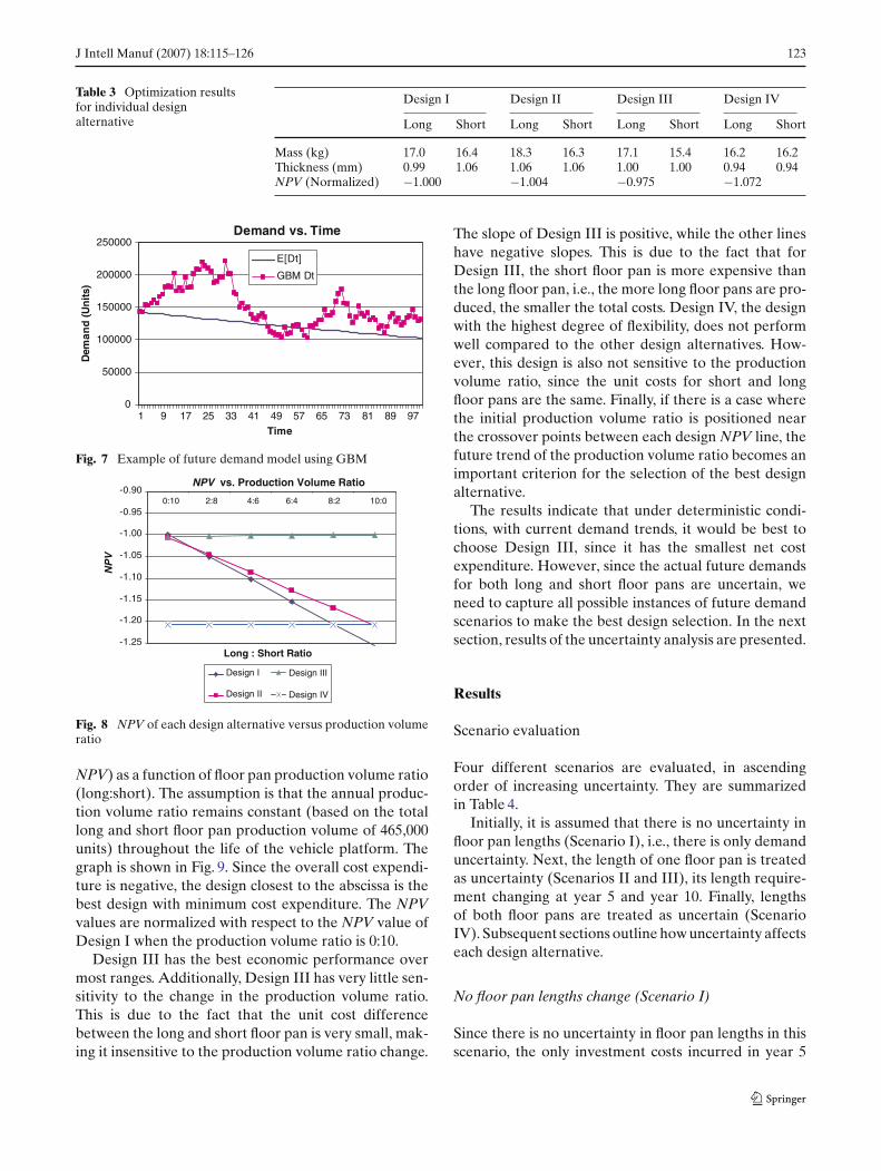
Fig. 7 Example of future demand model using GBM
NPV vs. Production Volume Ratio
-1.25
-1.20
-1.15
-1.10
-1.05
-1.00
-0.95
-0.900:10 2:8 4:6 6:4 8:2 10:0
Long : Short Ratio
NP
V
Design I
Design II
Design III
Design IV
Fig. 8 NPV of each design alternative versus production volumeratio
NPV) as a function of floor pan production volume ratio(long:short). The assumption is that the annual produc-tion volume ratio remains constant (based on the totallong and short floor pan production volume of 465,000units) throughout the life of the vehicle platform. Thegraph is shown in Fig. 9. Since the overall cost expendi-ture is negative, the design closest to the abscissa is thebest design with minimum cost expenditure. The NPVvalues are normalized with respect to the NPV value ofDesign I when the production volume ratio is 0:10.
Design III has the best economic performance overmost ranges. Additionally, Design III has very little sen-sitivity to the change in the production volume ratio.This is due to the fact that the unit cost differencebetween the long and short floor pan is very small, mak-ing it insensitive to the production volume ratio change.
The slope of Design III is positive, while the other lineshave negative slopes. This is due to the fact that forDesign III, the short floor pan is more expensive thanthe long floor pan, i.e., the more long floor pans are pro-duced, the smaller the total costs. Design IV, the designwith the highest degree of flexibility, does not performwell compared to the other design alternatives. How-ever, this design is also not sensitive to the productionvolume ratio, since the unit costs for short and longfloor pans are the same. Finally, if there is a case wherethe initial production volume ratio is positioned nearthe crossover points between each design NPV line, thefuture trend of the production volume ratio becomes animportant criterion for the selection of the best designalternative.
The results indicate that under deterministic condi-tions, with current demand trends, it would be best tochoose Design III, since it has the smallest net costexpenditure. However, since the actual future demandsfor both long and short floor pans are uncertain, weneed to capture all possible instances of future demandscenarios to make the best design selection. In the nextsection, results of the uncertainty analysis are presented.
Results
Scenario evaluation
Four different scenarios are evaluated, in ascendingorder of increasing uncertainty. They are summarizedin Table 4.
Initially, it is assumed that there is no uncertainty infloor pan lengths (Scenario I), i.e., there is only demanduncertainty. Next, the length of one floor pan is treatedas uncertainty (Scenarios II and III), its length require-ment changing at year 5 and year 10. Finally, lengthsof both floor pans are treated as uncertain (ScenarioIV). Subsequent sections outline how uncertainty affectseach design alternative.
No floor pan lengths change (Scenario I)
Since there is no uncertainty in floor pan lengths in thisscenario, the only investment costs incurred in year 5

124 J Intell Manuf (2007) 18:115–126
Value of Flexibility vs. Degree of Uncertainty
-100.00
-80.00
-60.00
-40.00
-20.00
0.00
20.00
2 310
Uncertainty in Floor Pan Length
NP
V D
iffe
ren
ce
E[NPV (II)] - E[NPV (I)] E[NPV (III)] - E[NPV (I)]
E[NPV (IV)] - E[NPV (I)]
Fig. 9 Value of flexibility
and 10 are refurbishing costs of fabrication dies. MonteCarlo simulation is performed to estimate the expectedlifetime cost expenditure for each design alternative.Each simulation comprises 25,000 runs.
Uncertain short floor pan length (Scenario II)
This time, the short floor pan length is treated as uncer-tain. The short floor pan length changes occur in year5 and 10, when the vehicle family goes through majorredesign. Each design alternative will incur differentinvestment costs.
• Design I: A new stamping die and blanking die forthe short floor pan are required. Long floor pan diesare refurbished.
• Design II: New investments for both short floor panand the extension piece are required. For this design,flexibility does not have any benefit over the inflex-ible design.
• Design III: The blanking die that trims the long floorpan into the short floor pan must be redesigned.
• Design IV: No new investments, other than refur-bishing costs, are required. Flexibility is already builtin.
Again, Monte Carlo simulation is performed for eachdesign alternative.
Uncertain long floor pan length (Scenario III)
This time, the long floor pan length is treated as uncer-tain. The long floor pan length changes occur in year 5and 10, when the vehicle models are redesigned. Eachdesign alternative will incur different investmentcosts.
• Design I: A new long floor pan stamping die anda blanking die is required. Short floor pan dies arerefurbished.
• Design II: A new extension piece is required toaccommodate the new length. Blanking and stamp-ing dies for a new extension piece are required. Shortfloor pan dies are refurbished.
• Design III: A new stamping die and blanking die forthe long floor pan are required. The blanking die forthe short floor pan is refurbished.
• Design IV: No new investments, other than refur-bishing costs, are required. Flexibility is already builtin.
Uncertain floor pan lengths (Scenario IV)
Finally, both long and short floor pan lengths are treatedas uncertain. The floor pan length changes occur in year5 and 10 when the entire vehicle family goes through amajor change. Each design alternative will incur differ-ent investment costs.
• Design I: New stamping and blanking dies for bothlong and short floor pan are required.
• Design II: Investment costs for the short floor panand extension piece are required.
• Design III: New investment costs for the large floorpan (blanking and stamping dies) and blanking die(for short floor pan trimming) are required.
• Design IV: No new investments, other than refur-bishing costs, are required. Flexibility is already builtin.
Table 4 Evaluated scenarios Scenarios Short floor pan Long floor panlength (Year 5, 10) length (Year 5, 10)
Scenario I Fixed FixedScenario II Uncertain FixedScenario III Fixed UncertainScenario IV Uncertain Uncertain

J Intell Manuf (2007) 18:115–126 125
Table 5 E[NPV] of designalternatives for simulatedscenarios
Scenarios E[NPV] (Normalized)
I II III IV
Scenario I −1.000 −0.998 −0.987 −1.164Scenario II −1.076 −1.081 −1.055 −1.163Scenario III −1.075 −1.072 −1.061 −1.162Scenario IV −1.082 −1.079 −1.061 −1.161
Simulation results
Table 5 lists E[NPV] of each design alternative for allevaluated scenarios. Values are normalized with respectto the E[NPV] value of Design I for scenario I.
From the simulation, it appears that Design III hasthe best economic performance among all designs in allscenarios. Design II, another flexible design, had worseeconomic performance than the inflexible Design I inscenarios I and II. This can be attributed to the fact thatthe production volume trend (shown in Fig. 8) shiftedto the region where Design I becomes more favorable.Another influencing factor is the way the flexibility isbuilt into the floor pan for Design II. When the shortfloor pan length became uncertain, Design II needednew investments on all sub-components, resulting inhigher cost expenditures than Design I. Another inter-esting result is that Design IV, the most flexible design,had the worst economic performance overall, regard-less of degree of uncertainty. This raises a possible futureresearch question, “how much flexibility is optimal whenthe degree of uncertainty is known?”
The final analysis consists of comparing the differencebetween the economic performance of flexible designsto that of the inflexible design as the degree of uncer-tainty increases. Figure 9 shows the �E[NPV] betweenflexible designs (Designs II, III, and IV) and the inflex-ible design (Design I) as the degree of uncertainty infloor pan length increases.
The abscissa represents the degree of uncertainty inthe floor pan lengths. The floor pan lengths can be certainfor both long and short floor pans (degree = 0), uncertainfor one of the floor pans (degree = 1), or uncertain forboth floor pans (degree = 2). The ordinate represents thedifference between the average cost expenditure of flex-ible designs (Designs II, III, and IV) and the inflexibledesign (Design I). As observed in Fig. 9, it is clear thatflexibility has more value as the degree of uncertaintyincreases.
Discussion
The analysis results reveal important issues that must beconsidered when designing flexible platform components.
They are: the way flexibility is incorporated into the com-ponent, the degree of flexibility, and the production vol-ume ratio trend between variants in the product family.
First, the way flexibility is embedded into a compo-nent has very significant economic consequences overthe lifetime of the platform component. In this casestudy, Design III was almost always the best design interms of economic benefit, while the flexible Design IIperformed worse than the customized Design I undercertain circumstances. Also, Designs III and IV wereeconomically robust to uncertain production volumeratios due to small differences in long and short floorpan manufacturing costs. Design III is the component,which is optimized for the larger variant, with mate-rial being removed to create the shorter variant (“top-down”).
Second, consideration must be given to the degreeof future uncertainty. As demonstrated in the previoussection, the value of flexible design increased as thedegree of uncertainty increased. However, Design IV,the design with “continuous” flexibility, was too expen-sive and it failed to give the best return even when thedegree of uncertainty increased. In all scenarios, flexi-ble designs with “discrete” levels of flexibility performedmuch better.
Finally, the future trend of the production volumeratio between variants in the same product family can bean important factor. When the initial production volumeratio is near the crossover point, the future productionvolume ratio trend must be observed carefully in orderto select the best design.
The proposed design process provides a stepping-stone for future research, namely the design process forflexible complex systems (e.g., product platforms). Com-plex systems can respond to future uncertainties moreeasily by properly identifying and embedding flexibil-ity into a key subset of complex system elements. How-ever, one must take into account the interaction betweenrelated elements within the system, which were not pres-ent in the case of a single component discussed in thispaper. Further research on system change propagationand system decomposition strategy, in addition to workpresented in this paper, is needed to address thisproblem.

126 J Intell Manuf (2007) 18:115–126
Summary
In this paper, a design process for flexible product plat-form components is introduced. Embedding flexibilityallows manufacturers to respond to changing marketneeds with a minimum increase in investment costs andcomplexity. Once important product platform criteriaand future uncertainties are identified, several flexibledesign alternatives are generated. Each design alterna-tive is optimized for minimum cost expenditure whilesatisfying performance constraints. Uncertainty analy-sis is performed to determine the best design alternative.The design process is demonstrated through a detailedcase study, where flexible design alternatives for a vehi-cle floor pan are generated and evaluated for lifetimecost expenditure under uncertain demand and uncer-tain geometric specifications.
Results revealed that how flexibility is built into thecomponent has significant economic consequences overthe lifetime of the platform component. Additionally,it is demonstrated that as the degree of future uncer-tainty increases, the value of component-embedded flex-ibility increases. Analysis also demonstrated that toomuch flexibility may not result in the best economicperformance, which gives rise to the question “what isthe optimal degree of flexibility?” Production volumetrends for component variants are very important fac-tors to consider when there are several competing flex-ible designs. Finally, application of the proposed designprocess to a complex system is discussed as a promisingfuture research topic.
Acknowledgements The work presented in this paper was sup-ported by General Motors. Such support does not constitute anendorsement by the company of the conclusions expressed by theauthors in the paper.
References
Black, F., & Scholes, M. (1973). The pricing of option and corpo-rate liabilities. Journal of Political Economy, 81, 637–654.
Bremmer, R. (1999). Cutting edge platforms. Financial TimesAutomotive World, September, 30–38.
Cook, H. E. (1997). Product management: Value, quality, cost,price, profit and organization. New York, NY: Chapman &Hall
de Neufville, R. (1990). Applied systems analysis: Engineer-ing planning and technology management. New York, NY:McGraw-Hill
de Weck, O., Suh, E. S., & Chang, D. (2003). Product familyand platform portfolio optimization. Proceedings of the 2003Design Engineering Technical Conference, September 2–6,2003, Chicago, Illinois, USA, DETC2003/DAC-48721.
ESD Symposium Committee (2002). Engineering systemsresearch and practice. ESD Internal Symposium, May 29–31, 2002, Massachusetts Institute of Technology, Cambridge,MA.
Fellini, R., Kokkolaras, M., Michelena, N., Papalambros, P., Sa-itou, K., Perez-Duarte, A., & Fenyes, P. A. (2002). A sen-sitivity-based commonality strategy for family products ofmild variation, with application to automotive body struc-tures. Proceedings of the 9th AIAA/ISSMO Symposium onMultidisciplinary Analysis and Optimization, September 4–6,2002, Atalanta, Georgia, USA, AIAA-2002–5610.
Georgiopoulos, P., Fellini, R., Sasena, M., & Papalambros, P. Y.(2002). Optimal design decisions in product portfolio valua-tion. Proceedings of 2002 Design Engineering Technical Con-ference, September 29–October 2, 2002, Montreal, Canada,DETC2002/DAC-34097.
Kidd, S. L. (1998). A systematic method for valuing a product plat-form strategy. LFM Master Thesis. Massachusetts Institute ofTechnology, Cambridge, MA.
Li, H., & Azarm, S. (2000) Product design selection under uncer-tainty and with competitive advantage. Journal of MechanicalDesign, 122(4), 411–418.
Li, H., & Azarm, S. (2002). An approach for product line designselection under uncertainty and competition. Journal ofMechanical Design, 124(3), 385–392.
Martin, M. V., & Ishii, K. (2002) Design for variety: Develop-ing standardized and modularized product platform architec-tures. Research in Engineering Design, 13(4), 213–235.
Meyer, M. H., & Lehnerd, A. P. (1997). The power of productplatforms: Building value and cost leadership. New York, NY:The Free Press.
Nelson, S. A., II, Parkinson, M. B., & Papalambros, P. Y. (2001).Multicriteria optimization in product platform design. Jour-nal of Mechanical Design, 123(2), 199–204.
Pine, B. J. (1993) Mass customization: The new frontier in businesscompetition. Boston, MA: Harvard Business School Press.
Robertson, D., & Ulrich, K. (1998). Planning product platforms.Sloan Management Review, 39(4), 19–31.
Sanderson, S. W., & Uzumeri, M. (1997). Managing product fam-ilies. Chicago, IL: Irwin Professional Publication
Sethi, A. K., & Sethi, S. P. (1990). Flexibility in manufacturing: Asurvey. The International Journal of Flexible ManufacturingSystems, 2, 289–328.
Simpson, T. W., Maier, J. R. A., & Mistree, F. (2001) Productplatform design: Method and application. Research in Engi-neering Design, 13(1), 2–22.
Trigeorgis, L. (1996) Real options: Managerial flexibility and strat-egy in resource allocation. Cambridge, MA: The MIT Press.