flexible carbon nanotube modified separator for … 2017, 7, 196 3 of 10 nanomaterials 2017, 7, 196...
TRANSCRIPT
nanomaterials
Article
Flexible Carbon Nanotube Modified Separatorfor High-Performance Lithium-Sulfur Batteries
Bin Liu 1, Xiaomeng Wu 1, Shan Wang 1,*, Zhen Tang 1, Quanling Yang 1, Guo-Hua Hu 1,2
and Chuanxi Xiong 1,*1 State Key Laboratory of Advanced Technology for Materials Synthesis and Processing,
School of Materials Science and Engineering, Wuhan University of Technology, Wuhan 430070, China;[email protected] (B.L.); [email protected](X.W.); [email protected] (Z.T.);[email protected] (Q.Y.); [email protected] (G.-H.H.)
2 Laboratory of Reactions and Process Engineering (LRGP, CNRS UMR 7274), CNRS-University of Lorraine,1rue Grandville, BP 20451, 54001 Nancy, France
* Correspondence: [email protected] (S.W.); [email protected] (C.X.); Tel.: +86-027-8738-7481 (C.X.)
Received: 10 July 2017; Accepted: 21 July 2017; Published: 26 July 2017
Abstract: Lithium-sulfur (Li-S) batteries have become promising candidates for electrical energystorage systems due to their high theoretical specific energy density, low cost and environmentalfriendliness. However, there are some technical obstacles of lithium-sulfur batteries to be addressed,such as the shuttle effect of polysulfides. Here, we introduced organically modified carbon nanotubes(CNTs) as a coating layer for the separator to optimize structure and enhance the performance of theLi-S battery. The results showed that the cell with a CNTs-coated separator exhibited an excellentcycling performance. Compared to the blank separator, the initial discharge capacity and the capacityafter 100 cycles for the CNTs-coated separator was increased by 115% and 161%, respectively. Besides,according to the rate capability test cycling from 0.1C to 2C, the battery with a CNTs-coated separatorstill released a capacity amounting to 90.2% of the initial capacity, when the current density returnedback to 0.1C. It is believed that the organically modified CNTs coating effectively suppresses theshuttle effect during the cycling. The employment of a CNTs-coated separator provides a promisingapproach for high-performance lithium-sulfur batteries.
Keywords: Lithium-sulfur batteries; carbon nanotubes; separators; shuttle effect
1. Introduction
Nowadays, rechargeable lithium batteries have been widely used in portable electronics, electricvehicles and various energy storage devices. Lithium-sulfur (Li-S) batteries have been considered tobe one of the most promising choices for next generation, high-energy rechargeable batteries due totheir high theoretical energy density. For lithium-ion batteries with graphite as negative electrodes,the theoretical energy densities are typically limited to around 400 Wh/kg or 1400 Wh/L [1,2],while the theoretical energy densities of lithium-sulfur batteries are calculated to be 2500 Wh/kg or2800 Wh/L [3,4]. Also sulfur offers a theoretical capacity of 1675 mAh/g, which is higher than thoseof transition-metal oxide electrode materials by an order of magnitude [5]. Additionally, the merits ofabundant reserves, low cost and environmental friendliness of sulfur are greatly in favor of large-scalecommercialization of Li-S batteries.
In spite of these advantages, there are still great challenges limiting the practical applicationof Li-S batteries. On one hand, there is low utilization of the active materials in the cathode sinceboth sulfur and its discharge product Li2S are electronically and ionically insulating. On the otherhand, due to the soluble characteristics and thus the shuttle behavior of the polysulfide intermediates(Li2Sx, 4 ≤ x ≤ 8), which are generated during the charge/discharge process, irreversible capacity loss
Nanomaterials 2017, 7, 196; doi:10.3390/nano7080196 www.mdpi.com/journal/nanomaterials

Nanomaterials 2017, 7, 196 2 of 10
is commonly unavoidable. This consequently leads to low coulombic efficiency and poor cycle life forLi-S batteries [6].
To address these key issues, great efforts have been devoted in the past decades mainly towardimproving the electrochemical performance of the sulfur cathode. A variety of carbon materials suchas carbon nanofibers [7], graphene [8,9] and porous carbon [10] have been employed to fabricatesulfur/carbon composite cathode to enhance the conductivity of sulfur as well as to suppressthe diffusion of dissolved polysulfides out of the cathode. Also conductive polymers have beenadopted and have demonstrated their role in improving the electrochemical performance of the sulfurcathode [11]. However, the enhanced electrochemical performance is usually compromised by thelower sulfur loading mass in the cathode, which greatly reduces the practical energy density of Li-Sbatteries. Alternatively, a promising strategy based on modifying the separator with conductivematerials (e.g., Super P, Ketjen Black) has been recently proposed and demonstrated its greateffectiveness on improving the rate capability and cycle life of Li-S batteries [12,13]. As an essentialpart of batteries, separators are placed between anode and cathode to prevent physical contact ofthe electrodes during the free ion transfer process. The properties of separators such as composition,porosity and wettability can affect the energy density, cycle life and safety of the battery [14]. It wasclaimed that the conductive coating or layer on separator could facilitate electron or ion transport,enhance electrolyte uptake, and inhibit the shuttle effect of polysulfides [15].
Owing to their outstanding electrical conductivity, one-dimensional carbon nanotubes (CNTs)have attracted considerable interest in the field of the lithium sulfur battery, especially in termsof the electrodes [16,17]. Few studies have involved coating the separator with CNTs due to theirentanglement, poor solubility and dispersion in solvents. Chung et al. fabricated CNTs-coatedseparator by a simple vacuum filtration technique, and the results showed that Li-S battery withthe modified separator possessed high discharge capacity, excellent rate performance and long cyclelife [18]. However, low efficiency and safety problems (i.e., separator rupture) may be involved in thevacuum filtration process. Therefore, it is highly desirable to design a facile but efficient route to applythe CNTs coating on the commercial separator.
In this work, flexible carbon nanotubes were first prepared by oxidation followed by a graftingroute. Then the modified CNTs were spin coated onto the surface of the commercial separator,and assembled into Li-S battery. The electrochemical performance of lithium-sulfur batteries wascomprehensively studied. The hydrophilic groups and reticular structure in the organically modifiedCNTs coating layer effectively suppressed the shuttle effect by trapping dissolved long-chain lithiumpolysulfides(Li2Sx, x = 4, 6, 8). The introduction of organically modified CNTs enhanced thethermal shrinkage property of the separator, which is beneficial for its practical application. Besides,the conductive nature of CNTs also benefited the decrease of the internal resistance. To sum up,modified CNTs-coated separators are promising for high performance lithium-sulfur batteries.
2. Results and Discussion
2.1. Morphology and Structural Characterization
As shown in Figure 1a, the organic modification process of carbon nanotubes consisted of threesuccessive steps. Carbon nanotubes were first oxidized by a mixed, concentrated acid of H2SO4 andHNO3, resulting in a great amount of hydrophilic groups including carboxyl and hydroxyl on thesurface of carbon nanotubes. An organic silane ((CH3O)3Si(CH2)3N+(CH3)2(C18H37)Cl−) (DC 5700)was adopted to couple and a long-chain protonic acid containing a polyethylene glycol segment(C9H19-C6H4-O(CH2CH2O)10SO3
−Na+) (NPES) was applied to exchange ion successively [19,20].The as-obtained products were spin coated onto the commercial Celgard 2325 separator and the coatedseparators were assembled into lithium-sulfur batteries. As shown in Figure 1b, the coated separatorswere designed to trap and prevent lithium polysulfides from crossing the separators, which wouldeffectively suppress the shuttle effect.

Nanomaterials 2017, 7, 196 3 of 10
Nanomaterials 2017, 7, 196 3 of 10
separators were designed to trap and prevent lithium polysulfides from crossing the separators, which would effectively suppress the shuttle effect.
Figure 1. Schematic illustration of (a) organic modification process of carbon nanotubes and (b) cell configuration of lithium-sulfur (Li-S) batteries.
Typical transmission electron microscope (TEM) images of the original and oxidized CNTs are shown in Figure 2a,b. Comparing to the original CNTs, it is found that less entanglements are present for the oxidized CNTs. This could be due to the successful introduction of some hydrophilic groups such as hydroxyl and carboxyl in the oxidized process, consequently leading to an improved dispersion of CNTs in water. Figure 2c shows the TEM of the synthesized CNTs. It can be seen that the CNTs are surrounded by a shell structure with a thickness of about 1 nm, which is the organic shell formed by DC 5700 and NPES long-chain molecules grafted on the CNTs surface. After graft modification, the entanglement of CNTs reduced greatly. The CNTs could be easily dispersed in some solvents such as chloroform, and form a homogeneous slurry state, which facilitates the coating technique.
Figure 2. TEM images of (a) original carbon nanotubes (CNTs), (b) oxidized CNTs and (c) organically modified CNTs.
Figure 3 compares the Fourier transform infrared (FTIR) spectra of the oxidized and organically modified CNTs. Some additional characteristic peaks can be distinctively observed in the spectrum of the organically modified CNTs. Specifically, characteristic peaks around 2925 cm−1
and 2856 cm−1 corresponded to the stretching vibration of methyl and methylene, while the peak at 1467 cm−1 represented the bending vibration of methylene. The peak at 1251 cm−1 was characteristic of the –SO3 group and the peaks of 1170 cm−1 and 1029 cm−1 were attributed to the Si–O–Si vibration. Besides, it was found that the vibration strength of the hydroxyl peak at 3450 cm−1 reduced for the
Figure 1. Schematic illustration of (a) organic modification process of carbon nanotubes and(b) cell configuration of lithium-sulfur (Li-S) batteries.
Typical transmission electron microscope (TEM) images of the original and oxidized CNTs areshown in Figure 2a,b. Comparing to the original CNTs, it is found that less entanglements are presentfor the oxidized CNTs. This could be due to the successful introduction of some hydrophilic groupssuch as hydroxyl and carboxyl in the oxidized process, consequently leading to an improved dispersionof CNTs in water. Figure 2c shows the TEM of the synthesized CNTs. It can be seen that the CNTsare surrounded by a shell structure with a thickness of about 1 nm, which is the organic shell formedby DC 5700 and NPES long-chain molecules grafted on the CNTs surface. After graft modification,the entanglement of CNTs reduced greatly. The CNTs could be easily dispersed in some solvents suchas chloroform, and form a homogeneous slurry state, which facilitates the coating technique.
Nanomaterials 2017, 7, 196 3 of 10
separators were designed to trap and prevent lithium polysulfides from crossing the separators, which would effectively suppress the shuttle effect.
Figure 1. Schematic illustration of (a) organic modification process of carbon nanotubes and (b) cell configuration of lithium-sulfur (Li-S) batteries.
Typical transmission electron microscope (TEM) images of the original and oxidized CNTs are shown in Figure 2a,b. Comparing to the original CNTs, it is found that less entanglements are present for the oxidized CNTs. This could be due to the successful introduction of some hydrophilic groups such as hydroxyl and carboxyl in the oxidized process, consequently leading to an improved dispersion of CNTs in water. Figure 2c shows the TEM of the synthesized CNTs. It can be seen that the CNTs are surrounded by a shell structure with a thickness of about 1 nm, which is the organic shell formed by DC 5700 and NPES long-chain molecules grafted on the CNTs surface. After graft modification, the entanglement of CNTs reduced greatly. The CNTs could be easily dispersed in some solvents such as chloroform, and form a homogeneous slurry state, which facilitates the coating technique.
Figure 2. TEM images of (a) original carbon nanotubes (CNTs), (b) oxidized CNTs and (c) organically modified CNTs.
Figure 3 compares the Fourier transform infrared (FTIR) spectra of the oxidized and organically modified CNTs. Some additional characteristic peaks can be distinctively observed in the spectrum of the organically modified CNTs. Specifically, characteristic peaks around 2925 cm−1
and 2856 cm−1 corresponded to the stretching vibration of methyl and methylene, while the peak at 1467 cm−1 represented the bending vibration of methylene. The peak at 1251 cm−1 was characteristic of the –SO3 group and the peaks of 1170 cm−1 and 1029 cm−1 were attributed to the Si–O–Si vibration. Besides, it was found that the vibration strength of the hydroxyl peak at 3450 cm−1 reduced for the
Figure 2. TEM images of (a) original carbon nanotubes (CNTs), (b) oxidized CNTs and (c) organicallymodified CNTs.
Figure 3 compares the Fourier transform infrared (FTIR) spectra of the oxidized and organicallymodified CNTs. Some additional characteristic peaks can be distinctively observed in the spectrum ofthe organically modified CNTs. Specifically, characteristic peaks around 2925 cm−1 and 2856 cm−1
corresponded to the stretching vibration of methyl and methylene, while the peak at 1467 cm−1
represented the bending vibration of methylene. The peak at 1251 cm−1 was characteristic of the –SO3
group and the peaks of 1170 cm−1 and 1029 cm−1 were attributed to the Si–O–Si vibration. Besides,it was found that the vibration strength of the hydroxyl peak at 3450 cm−1 reduced for the organically

Nanomaterials 2017, 7, 196 4 of 10
modified CNTs, indicating that the amount of hydroxyl groups decreased due to the reaction betweenthe CNTs and the organic silane DC 5700. Combined with the chemical structure of the DC 5700 andNPES, it was reasonably deduced that the organic modifiers have been successfully grafted onto thewalls of CNTs in this study.
Nanomaterials 2017, 7, 196 4 of 10
organically modified CNTs, indicating that the amount of hydroxyl groups decreased due to the reaction between the CNTs and the organic silane DC 5700. Combined with the chemical structure of the DC 5700 and NPES, it was reasonably deduced that the organic modifiers have been successfully grafted onto the walls of CNTs in this study.
Figure 3. FTIR spectra of (a) oxidized CNTs and (b) organically modified CNTs.
Figure 4a,b show the scanning electron microscope (SEM) images of the blank and CNTs-coated separators, respectively. Typically, the blank separator displayed uniform slit-like micropores with a length of about 280 nm and a width of about 70 nm. It is known that these nanosized micropores could provide a convenient channel for transporting the free lithium ion. Unfortunately, it was also said that this type of micropore allowed the shuttle of the dissolved polysulfides during the charge/discharge process, which consequently deteriorated the rate performance and shortened the cycle life [21]. While for the CNTs-coated separator, it is clear that the tubular carbon materials were uniformly adhered to the surface of the separator and the original porous structure was entirely covered. The long CNT tubes intertwined with each other and constructed a large number of nanosized pore structure in the coating layer. According to previous reports, this structure could facilitate the storage of the polysulfide intermediates [18].
Figure 4. SEM images of (a) blank separator and (b) CNTs-coated separator.
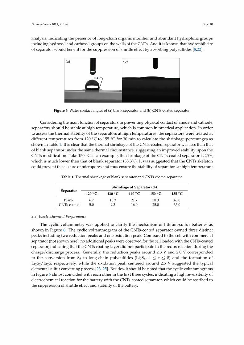
Essentially, the surface chemistry property of separator plays an important role in controlling the diffusion of polysulfides. Considering the water contact angle (WCA) can reflect the polarity of the separators, WCA measurements were carried out as shown in Figure 5. The WCA of the blank separator was approximately 114.0° (Figure 5a), which associated well with the hydrophobic nature of the polypropylene-based separator. In contrast, the water droplet quickly spread as soon as it contacted with the surface of the CNTs-coated separator, and the WCA measured at 10 s was only about 15°, suggesting a good hydrophilicity. The result was in consistence with the previous FTIR analysis, indicating the presence of long-chain organic modifier and abundant hydrophilic groups including hydroxyl and carboxyl groups on the walls of the CNTs. And it is known that hydrophilicity of separator would benefit for the suppression of shuttle effect by absorbing polysulfides [8,22].
Figure 3. FTIR spectra of (a) oxidized CNTs and (b) organically modified CNTs.
Figure 4a,b show the scanning electron microscope (SEM) images of the blank and CNTs-coatedseparators, respectively. Typically, the blank separator displayed uniform slit-like micropores witha length of about 280 nm and a width of about 70 nm. It is known that these nanosized microporescould provide a convenient channel for transporting the free lithium ion. Unfortunately, it wasalso said that this type of micropore allowed the shuttle of the dissolved polysulfides during thecharge/discharge process, which consequently deteriorated the rate performance and shortened thecycle life [21]. While for the CNTs-coated separator, it is clear that the tubular carbon materialswere uniformly adhered to the surface of the separator and the original porous structure was entirelycovered. The long CNT tubes intertwined with each other and constructed a large number of nanosizedpore structure in the coating layer. According to previous reports, this structure could facilitate thestorage of the polysulfide intermediates [18].
Nanomaterials 2017, 7, 196 4 of 10
organically modified CNTs, indicating that the amount of hydroxyl groups decreased due to the reaction between the CNTs and the organic silane DC 5700. Combined with the chemical structure of the DC 5700 and NPES, it was reasonably deduced that the organic modifiers have been successfully grafted onto the walls of CNTs in this study.
Figure 3. FTIR spectra of (a) oxidized CNTs and (b) organically modified CNTs.
Figure 4a,b show the scanning electron microscope (SEM) images of the blank and CNTs-coated separators, respectively. Typically, the blank separator displayed uniform slit-like micropores with a length of about 280 nm and a width of about 70 nm. It is known that these nanosized micropores could provide a convenient channel for transporting the free lithium ion. Unfortunately, it was also said that this type of micropore allowed the shuttle of the dissolved polysulfides during the charge/discharge process, which consequently deteriorated the rate performance and shortened the cycle life [21]. While for the CNTs-coated separator, it is clear that the tubular carbon materials were uniformly adhered to the surface of the separator and the original porous structure was entirely covered. The long CNT tubes intertwined with each other and constructed a large number of nanosized pore structure in the coating layer. According to previous reports, this structure could facilitate the storage of the polysulfide intermediates [18].
Figure 4. SEM images of (a) blank separator and (b) CNTs-coated separator.
Essentially, the surface chemistry property of separator plays an important role in controlling the diffusion of polysulfides. Considering the water contact angle (WCA) can reflect the polarity of the separators, WCA measurements were carried out as shown in Figure 5. The WCA of the blank separator was approximately 114.0° (Figure 5a), which associated well with the hydrophobic nature of the polypropylene-based separator. In contrast, the water droplet quickly spread as soon as it contacted with the surface of the CNTs-coated separator, and the WCA measured at 10 s was only about 15°, suggesting a good hydrophilicity. The result was in consistence with the previous FTIR analysis, indicating the presence of long-chain organic modifier and abundant hydrophilic groups including hydroxyl and carboxyl groups on the walls of the CNTs. And it is known that hydrophilicity of separator would benefit for the suppression of shuttle effect by absorbing polysulfides [8,22].
Figure 4. SEM images of (a) blank separator and (b) CNTs-coated separator.
Essentially, the surface chemistry property of separator plays an important role in controllingthe diffusion of polysulfides. Considering the water contact angle (WCA) can reflect the polarity ofthe separators, WCA measurements were carried out as shown in Figure 5. The WCA of the blankseparator was approximately 114.0◦ (Figure 5a), which associated well with the hydrophobic natureof the polypropylene-based separator. In contrast, the water droplet quickly spread as soon as itcontacted with the surface of the CNTs-coated separator, and the WCA measured at 10 s was onlyabout 15◦, suggesting a good hydrophilicity. The result was in consistence with the previous FTIR
Nanomaterials 2017, 7, 196 5 of 10
analysis, indicating the presence of long-chain organic modifier and abundant hydrophilic groupsincluding hydroxyl and carboxyl groups on the walls of the CNTs. And it is known that hydrophilicityof separator would benefit for the suppression of shuttle effect by absorbing polysulfides [8,22].Nanomaterials 2017, 7, 196 5 of 10
Figure 5. Water contact angles of (a) blank separator and (b) CNTs-coated separator.
Considering the main function of separators in preventing physical contact of anode and cathode, separators should be stable at high temperature, which is common in practical application. In order to assess the thermal stability of the separators at high temperatures, the separators were treated at different temperatures from 120 °C to 155 °C for 30 min to calculate the shrinkage percentages as shown in Table 1. It is clear that the thermal shrinkage of the CNTs-coated separator was less than that of blank separator under the same thermal circumstance, suggesting an improved stability upon the CNTs modification. Take 150 °C as an example, the shrinkage of the CNTs-coated separator is 25%, which is much lower than that of blank separator (38.3%). It was suggested that the CNTs skeleton could prevent the closure of micropores and thus ensure the stability of separators at high temperature.
Table 1. Thermal shrinkage of blank separator and CNTs-coated separator.
Separator Shrinkage of Separator (%)
120 °C 130 °C 140 °C 150 °C 155 °C Blank 6.7 10.3 21.7 38.3 43.0
CNTs-coated 5.0 9.3 16.0 25.0 35.0
2.2. Electrochemical Performance
The cyclic voltammetry was applied to clarify the mechanism of lithium-sulfur batteries as shown in Figure 6. The cyclic voltammogram of the CNTs-coated separator owned three distinct peaks including two reduction peaks and one oxidation peak. Compared to the cell with commercial separator (not shown here), no additional peaks were observed for the cell loaded with the CNTs-coated separator, indicating that the CNTs coating layer did not participate in the redox reaction during the charge/discharge process. Generally, the reduction peaks around 2.3 V and 2.0 V corresponded to the conversion from S8 to long-chain polysulfides (Li2Sx, 4 ≤ x ≤ 8) and the formation of Li2S2/Li2S, respectively, while the oxidation peak centered around 2.5 V suggested the typical elemental sulfur converting process [23–25]. Besides, it should be noted that the cyclic voltammograms in Figure 6 almost coincided with each other in the first three cycles, indicating a high reversibility of electrochemical reaction for the battery with the CNTs-coated separator, which could be ascribed to the suppression of shuttle effect and stability of the battery.
Figure 7a compares the discharge capacity of the Li-S batteries with the blank separator and CNTs-coated separator. It was found that the cell with the CNTs-coated separator delivered an initial discharge capacity as high as 1179 mAh/g at 0.1C while the cell with the blank separator only delivered an initial value of 547 mAh/g. In addition, the discharge capacity of the CNTs-coated and blank separators remained at 595 mAh/g and 228 mAh/g after 100 cycles, suggesting the capacity retention rates of 50.6% and 41.7%, respectively. This suggested that modification of the separator with the CNTs coating improved not only the initial discharge capacity but also the capacity retention rate. The improvement should be ascribed to the CNTs coating, which was capable of trapping long-chain polysulfides during the cycling.
Figure 5. Water contact angles of (a) blank separator and (b) CNTs-coated separator.
Considering the main function of separators in preventing physical contact of anode and cathode,separators should be stable at high temperature, which is common in practical application. In orderto assess the thermal stability of the separators at high temperatures, the separators were treated atdifferent temperatures from 120 ◦C to 155 ◦C for 30 min to calculate the shrinkage percentages asshown in Table 1. It is clear that the thermal shrinkage of the CNTs-coated separator was less than thatof blank separator under the same thermal circumstance, suggesting an improved stability upon theCNTs modification. Take 150 ◦C as an example, the shrinkage of the CNTs-coated separator is 25%,which is much lower than that of blank separator (38.3%). It was suggested that the CNTs skeletoncould prevent the closure of micropores and thus ensure the stability of separators at high temperature.
Table 1. Thermal shrinkage of blank separator and CNTs-coated separator.
SeparatorShrinkage of Separator (%)
120 ◦C 130 ◦C 140 ◦C 150 ◦C 155 ◦C
Blank 6.7 10.3 21.7 38.3 43.0CNTs-coated 5.0 9.3 16.0 25.0 35.0
2.2. Electrochemical Performance
The cyclic voltammetry was applied to clarify the mechanism of lithium-sulfur batteries asshown in Figure 6. The cyclic voltammogram of the CNTs-coated separator owned three distinctpeaks including two reduction peaks and one oxidation peak. Compared to the cell with commercialseparator (not shown here), no additional peaks were observed for the cell loaded with the CNTs-coatedseparator, indicating that the CNTs coating layer did not participate in the redox reaction during thecharge/discharge process. Generally, the reduction peaks around 2.3 V and 2.0 V correspondedto the conversion from S8 to long-chain polysulfides (Li2Sx, 4 ≤ x ≤ 8) and the formation ofLi2S2/Li2S, respectively, while the oxidation peak centered around 2.5 V suggested the typicalelemental sulfur converting process [23–25]. Besides, it should be noted that the cyclic voltammogramsin Figure 6 almost coincided with each other in the first three cycles, indicating a high reversibility ofelectrochemical reaction for the battery with the CNTs-coated separator, which could be ascribed tothe suppression of shuttle effect and stability of the battery.

Nanomaterials 2017, 7, 196 6 of 10
Nanomaterials 2017, 7, 196 6 of 10
Figure 6. Cyclic voltammograms of the cells with CNTs-coated separator.
The cycling performance of the Li-S battery with the CNTs-coated separator at high rates was further analyzed as shown in Figure 7b. The reversible capacity of the battery dropped from 684 mAh/g to 361 mAh/g at 1C in 500 cycles, with a coulombic efficiency of 96.7% on average and a capacity retention rate of 52.8%. When the rate increased to 2C, the initial discharge capacity of the battery was 414 mAh/g and remained 200 mAh/g after 500 cycles, suggesting an average capacity decay rate of only 0.1% per cycle. The coulombic efficiency also kept as high as 96.8%. The result is encouraging since it suggested the CNTs coating in the work could maintain the structural stability of the battery. That is to say, it would not collapse, even as the charge and discharge occurs rapidly, consequently leading to a long cycle life of the Li-S battery at high current density. Figure 7c presents the rate performance of the Li-S batteries with the CNTs-coated separator. With an initial value of 887 mAh/g at 0.1C, the capacity remained around 720, 620, 545 and 430 mAh/g at 0.2C, 0.5C, 1C and 2C in 10 cycles, respectively, and returned back to 800 mAh/g when the rate was 0.1C. The excellent reversibility of the capacity as high as 90.2% supported strongly again that the Li-S battery with CNTs-coated separator was highly stable and reversible.
Figure 7. (a) Cycling performance of the blank separator and CNTs-coated separator at 0.1C; (b) Cycling performance of the CNTs-coated separator at the rates of 1C and 2C; (c) Rate performance
Figure 6. Cyclic voltammograms of the cells with CNTs-coated separator.
Figure 7a compares the discharge capacity of the Li-S batteries with the blank separator andCNTs-coated separator. It was found that the cell with the CNTs-coated separator delivered aninitial discharge capacity as high as 1179 mAh/g at 0.1C while the cell with the blank separator onlydelivered an initial value of 547 mAh/g. In addition, the discharge capacity of the CNTs-coated andblank separators remained at 595 mAh/g and 228 mAh/g after 100 cycles, suggesting the capacityretention rates of 50.6% and 41.7%, respectively. This suggested that modification of the separator withthe CNTs coating improved not only the initial discharge capacity but also the capacity retention rate.The improvement should be ascribed to the CNTs coating, which was capable of trapping long-chainpolysulfides during the cycling.
Nanomaterials 2017, 7, 196 6 of 10
Figure 6. Cyclic voltammograms of the cells with CNTs-coated separator.
The cycling performance of the Li-S battery with the CNTs-coated separator at high rates was further analyzed as shown in Figure 7b. The reversible capacity of the battery dropped from 684 mAh/g to 361 mAh/g at 1C in 500 cycles, with a coulombic efficiency of 96.7% on average and a capacity retention rate of 52.8%. When the rate increased to 2C, the initial discharge capacity of the battery was 414 mAh/g and remained 200 mAh/g after 500 cycles, suggesting an average capacity decay rate of only 0.1% per cycle. The coulombic efficiency also kept as high as 96.8%. The result is encouraging since it suggested the CNTs coating in the work could maintain the structural stability of the battery. That is to say, it would not collapse, even as the charge and discharge occurs rapidly, consequently leading to a long cycle life of the Li-S battery at high current density. Figure 7c presents the rate performance of the Li-S batteries with the CNTs-coated separator. With an initial value of 887 mAh/g at 0.1C, the capacity remained around 720, 620, 545 and 430 mAh/g at 0.2C, 0.5C, 1C and 2C in 10 cycles, respectively, and returned back to 800 mAh/g when the rate was 0.1C. The excellent reversibility of the capacity as high as 90.2% supported strongly again that the Li-S battery with CNTs-coated separator was highly stable and reversible.
Figure 7. (a) Cycling performance of the blank separator and CNTs-coated separator at 0.1C; (b) Cycling performance of the CNTs-coated separator at the rates of 1C and 2C; (c) Rate performance Figure 7. (a) Cycling performance of the blank separator and CNTs-coated separator at 0.1C;(b) Cycling performance of the CNTs-coated separator at the rates of 1C and 2C; (c) Rate performanceof the Li-S batteries with the CNTs-coated separator; (d) EIS data of the cells with the blank separatorand CNTs-coated separator.

Nanomaterials 2017, 7, 196 7 of 10
The cycling performance of the Li-S battery with the CNTs-coated separator at high rates wasfurther analyzed as shown in Figure 7b. The reversible capacity of the battery dropped from684 mAh/g to 361 mAh/g at 1C in 500 cycles, with a coulombic efficiency of 96.7% on averageand a capacity retention rate of 52.8%. When the rate increased to 2C, the initial discharge capacity ofthe battery was 414 mAh/g and remained 200 mAh/g after 500 cycles, suggesting an average capacitydecay rate of only 0.1% per cycle. The coulombic efficiency also kept as high as 96.8%. The result isencouraging since it suggested the CNTs coating in the work could maintain the structural stabilityof the battery. That is to say, it would not collapse, even as the charge and discharge occurs rapidly,consequently leading to a long cycle life of the Li-S battery at high current density. Figure 7c presentsthe rate performance of the Li-S batteries with the CNTs-coated separator. With an initial value of887 mAh/g at 0.1C, the capacity remained around 720, 620, 545 and 430 mAh/g at 0.2C, 0.5C, 1C and2C in 10 cycles, respectively, and returned back to 800 mAh/g when the rate was 0.1C. The excellentreversibility of the capacity as high as 90.2% supported strongly again that the Li-S battery withCNTs-coated separator was highly stable and reversible.
Electrochemical impedance spectra (EIS) of the battery with and without CNTs-coated separatorare shown in Figure 7d. The Nyquist plots for this battery consisted of a semicircle in high frequencyregion, another in medium-to-low frequency region and an oblique line in the low-frequency region,which represented the resistance from a passivation film (Rt), the charge-transfer resistance (Rct) andWarburg impedance, respectively [26,27]. According to the previous reports, the diameter size of thesemicircle and slope size of the oblique line represented the value of impedance. It is clear that Rct andWarburg impedance are similar to each other for the different battery, while the Rt from a passivationfilm of the battery with CNTs-coated separator is less than that of the battery with blank separator.The results indicated that CNTs coating could significantly reduce the Rt, due to the conductive natureof CNTs and the enhanced electrolyte absorption capability. Similar to the previous study by otherresearchers, the enhanced electrical conductivity of the battery with CNTs coated separator led toa better rate capability and a high reversible capacity than that with blank separator [28]. The resultwas consistent with the preceding enhanced cycling performance.
3. Materials and Methods
3.1. Materials
Multi-walled carbon nanotubes (CNTs) were provided by Chengdu Organic Chemicals Co., Ltd.(Chengdu, Sichuan, China) Ethanol, chloroform, concentrated sulfuric acid (H2SO4, 98%), and concentratednitric acid (HNO3, 65%) were purchased from Sinopharm Chemical Reagent Co., Ltd. (Shanghai, China).Polysiloxane quaternary ammonium salt DC5700 [(CH3O)3Si(CH2)3N+(CH3)2(C18H37)Cl−] inmethanol (40%) was provided by Gelest (Morrisville, PA, USA). Sulfonate salt NPES[C9H19C6H4O(CH2CH2O)10SO3
−K+] was obtained from Aldrich (Shanghai, China). Sublimed sulfurwas purchased from Sinopharm Chemical Reagent Co., Ltd. (Shanghai, China). Celgard 2325from Celgard, LLC (Charlotte, NC, USA) was adopted as separator. Bis(trifluoromethane)sulfonamide lithium(LiTFSI), lithium nitrate (LiNO3, 99.99% trace metals basis), n-butyl alcohol(99%), N-methyl-2-pyrrolidone (NMP, 99%), 1,3-dioxolane (DOL) and 1,2-dimethoxyethane (DME)were obtained from Aladdin (Shanghai, China).
3.2. Preparation of CNTs-Coated Separator
Typically, CNTs were first oxidized in a mixture of concentrated H2SO4 and HNO3 with a volumeratio of 3:1 at 50 ◦C for 3 h. The suspension was then diluted with deionized water, followed bya centrifugation to remove the supernatant acid. The remaining solids were washed repeated withdeionized water until the pH value reached about 3. DC5700 was then added into the aqueous solutionof oxidized CNTs to render them cationic. The mixture was sonicated for 2 h, washed with water andanhydrous ethanol successively, and dried at 70 ◦C for 6 h. Subsequently, the resultants and a certain

Nanomaterials 2017, 7, 196 8 of 10
proportion of NPES were mixed in the chloroform solution. The mixture was stirred for 5 h at roomtemperature to ensure a full reaction, followed by a dialysis for 24 h in the deionized water bath tocompletely remove the KCl salt and excess sulfonate salt. Finally, the product was vacuum-dried at70 ◦C for 24 h to obtain the modified CNTs.
An appropriate amount of CNTs was dissolved in the chloroform to prepare the CNTs slurry.Then a small amount of CNTs slurry was spin-coated onto the surface of the virgin separator. Beforethe coating operation, the virgin separator was cleaned with anhydrous ethanol in an ultrasonic bathto remove any contamination. The coated separator was then dried in a vacuum oven at 50 ◦C for 24 h.
3.3. Characterizations
TEM images were made on a JEM 2100F field emission transmission electron microscope(Japan Electronics Co., Ltd., Tokyo, Japan). FTIR analysis was carried out using a Nicolet 6700 Fouriertransform infrared spectrometer (Thermo Fisher Scientific Inc., Waltham, WA, USA). The surfacemorphologies of the virgin and coated separators were observed using a field emission scanningelectron microscope (SEM, QUANTA FEG 450, FEI, Hillsboro, OR, USA). The water contact angles of theseparators were measured by a JC 2000C contact angle measuring instrument (Powereach, Shanghai, China).The thermal shrinkage ratio S was calculated according to the expression S = (L0 − L)/L0 × 100%,where L0 and L are the lengths of the separators before and after the thermal treatment, respectively.
The CR2032 coin cells were assembled in an argon-filled glove box to evaluate theelectrochemical performance of the virgin and CNTs-coated separator. The electrolyte was madeup of 1 M bis(triuoromethanesulfonyl)imide (LiTFSI) in dioxolane/dimethoxyethane solution(DOL/DME, V/V = 1:1) with 1 wt % LiNO3 additive. The cathode was prepared by mixingelemental sulfur, acetylene black and poly(vinylidene fluoride) with a weight ratio of 3:2:1 inN-methyl-2-pyrrolidinone. The slurry was coated on the aluminum foil and dried under vacuum toform the working cathode. Lithium metal foil was adopted as the anode. Cycling performance ofthe batteries was analyzed using a cell testing system (LAND CT2001A, Wuhan LAND electronics,Wuhan, China). Both the cyclic voltammetry curves (CV) and AC impedance of the battery weremeasured using a CHI 660E electrochemical workstation (CH Instruments, Shanghai, China).The voltage range was controlled in 1.5~3 V and the scanning rate was 0.1 mV/s. For the ACimpedance measurement, the scanning frequency range was controlled from 0.01 to 100 kHz, with anAC potential amplitude of 5 mV at the open-circuit potential.
4. Conclusions
In summary, we proposed a novel and effective method for the modification of separators inlithium-sulfur batteries. Grafted long-chain molecules and tube-like CNTs enable the formation ofmicropores in CNTs, which could accommodate polysulfides. The hydrophilic groups help trappingpolysulfides to suppress shuttle effect. The organically modified CNTs coating also facilitate thebattery with a high temperature stability. In addition, the conductive nature of CNTs also contributesto a decrease in internal resistance. The performance of the battery is improved significantly afteradopting our method, indicating new avenues for practical lithium-sulfur batteries.
Acknowledgments: Financial support from the National Science Foundation of China (grant No. 51673154) isgreatly acknowledged.
Author Contributions: Bin Liu conceived and designed the experiments; Bin Liu, Xiaomeng Wu and Zhen Tangperformed the experiments and analyzed the data; Bin Liu wrote the paper. Quanling Yang and Guo-Hua HUedited the paper. Shan Wang and Chuanxi Xiong proposed the project and supervised the paper.
Conflicts of Interest: The authors declare no conflicts of interest.

Nanomaterials 2017, 7, 196 9 of 10
References
1. Adelhelm, P.; Hartmann, P.; Bender, C.L.; Busche, M.; Eufinger, C.; Janek, J. From lithium to sodium:Cell chemistry of room temperature sodium-air and sodium-sulfur batteries. Beilstein J. Nanotechnol. 2015, 6,1016–1055. [CrossRef] [PubMed]
2. Whittingham, M.S. Ultimate limits to intercalation reactions for lithium batteries. Chem. Rev. 2014, 114,11414–11443. [CrossRef] [PubMed]
3. Evers, S.; Nazar, F.L. New Approaches for High Energy Density Lithium-Sulfur Battery Cathodes.Acc. Chem. Res. 2013, 46, 1135–1143. [CrossRef] [PubMed]
4. Seh, Z.W.; Sun, Y.; Zhang, Q.; Cui, Y. Designing high-energy lithium-sulfur batteries. Chem. Soc. Rev. 2016,45, 5605–5634. [CrossRef] [PubMed]
5. Manthiram, A.; Fu, Y.; Chung, S.H.; Zu, C.; Su, Y.S. Rechargeable lithium-sulfur batteries. Chem. Rev. 2014,114, 11751–11787. [CrossRef] [PubMed]
6. Chen, L.; Shaw, L.L. Recent advances in lithium–sulfur batteries. J. Power Sources 2014, 267, 770–783.[CrossRef]
7. Lee, J.S.; Kim, W.; Jang, J.; Manthiram, A. Sulfur-Embedded Activated Multichannel Carbon NanofiberComposites for Long-Life, High-Rate Lithium-Sulfur Batteries. Adv. Energy Mater. 2016, 7, 1601943.[CrossRef]
8. Wang, X.; Wang, Z.; Chen, L. Reduced graphene oxide film as a shuttle-inhibiting interlayer ina lithium–sulfur battery. J. Power Sources 2013, 242, 65–69. [CrossRef]
9. Jin, K.; Zhou, X.; Liu, Z. Graphene/Sulfur/Carbon Nanocomposite for High Performance Lithium-SulfurBatteries. Nanomaterials 2015, 5, 1481–1492. [CrossRef] [PubMed]
10. Chen, M.; Jiang, S.; Cai, S.; Wang, X.; Xiang, K.; Ma, Z.; Song, P.; Fisher, A.C. Hierarchical porous carbonmodified with ionic surfactants as efficient sulfur hosts for the high-performance lithium-sulfur batteries.Chem. Eng. J. 2017, 313, 404–414. [CrossRef]
11. Gao, H.; Lu, Q.; Yao, Y.; Wang, X.; Wang, F. Significantly Raising the Cell Performance of Lithium SulfurBattery via the Multifunctional Polyaniline Binder. Electrochim. Acta 2017, 232, 414–421. [CrossRef]
12. Yao, H.; Yan, K.; Li, W.; Zheng, G.; Kong, D.; Seh, Z.W.; Narasimhan, V.K.; Liang, Z.; Cui, Y. Improvedlithium–sulfur batteries with a conductive coating on the separator to prevent the accumulation of inactiveS-related species at the cathode–separator interface. Energy Environ. Sci. 2014, 7, 3381–3390. [CrossRef]
13. Chung, S.-H.; Manthiram, A. Bifunctional Separator with a Light-Weight Carbon-Coating for Dynamicallyand Statically Stable Lithium-Sulfur Batteries. Adv. Funct. Mater. 2014, 24, 5299–5306. [CrossRef]
14. Bai, S.; Liu, X.; Zhu, K.; Wu, S.; Zhou, H. Metal–organic framework-based separator for lithium–sulfurbatteries. Nano Energy 2016, 1, 16094. [CrossRef]
15. Song, R.; Fang, R.; Wen, L.; Shi, Y.; Wang, S.; Li, F. A trilayer separator with dual function for high performancelithium–sulfur batteries. J. Power Sources 2016, 301, 179–186. [CrossRef]
16. Guo, J.; Xu, Y.; Wang, C. Sulfur-impregnated disordered carbon nanotubes cathode for lithium-sulfurbatteries. Nano Lett. 2011, 11, 4288–4294. [CrossRef] [PubMed]
17. Lee, J.S.; Manthiram, A. Hydroxylated N-doped carbon nanotube-sulfur composites as cathodes forhigh-performance lithium-sulfur batteries. J. Power Sources 2017, 343, 54–59. [CrossRef]
18. Chung, S.H.; Manthiram, A. High-Performance Li-S Batteries with an Ultra-lightweight MWCNT-CoatedSeparator. J. Phys. Chem. Lett. 2014, 5, 1978–1983. [CrossRef] [PubMed]
19. Li, Q.; Dong, L.; Fang, J.; Xiong, C. Property-Structure Relationship of Nanoscale Ionic Materials Based onMultiwalled Carbon Nanotubes. ACS Nano 2010, 4, 5797–5806. [CrossRef] [PubMed]
20. Bourlinos, A.B.; Herrera, R.; Chalkias, N.; Jiang, D.D.; Zhang, Q.; Archer, L.A.; Giannelis, E.P.Surface Functionalized Nanoparticles with Liquid-like Behavior. Adv. Mater. 2005, 17, 234–237. [CrossRef]
21. Li, J.; Huang, Y.; Zhang, S.; Jiang, W.; Wang, X.; Guo, Y.; Jia, D.; Wang, L. Decoration of Silica Nanoparticleson Polypropylene Separator for Lithium–Sulfur Batteries. ACS Appl. Mater. Interfaces 2017, 9, 7499–7504.[CrossRef] [PubMed]
22. Zu, C.; Su, Y.S.; Fu, Y.; Manthiram, A. Improved lithium-sulfur cells with a treated carbon paper interlayer.Phys. Chem. Chem. Phys. 2013, 15, 2291–2297. [CrossRef] [PubMed]
Nanomaterials 2017, 7, 196 10 of 10
23. Wu, F.; Chen, J.; Chen, R.; Wu, S.; Li, L.; Chen, S.; Zhao, T. Sulfur/Polythiophene with a Core/Shell Structure:Synthesis and Electrochemical Properties of the Cathode for Rechargeable Lithium Batteries. J. Phys. Chem. C2011, 115, 6057–6063. [CrossRef]
24. Sun, J.; Huang, Y.; Wang, W.; Yu, Z.; Wang, A.; Yuan, K. Application of gelatin as a binder for the sulfurcathode in lithium–sulfur batteries. Electrochim. Acta 2008, 53, 7084–7088. [CrossRef]
25. Choi, J.-W.; Cheruvally, G.; Kim, D.-S.; Ahn, J.-H.; Kim, K.-W.; Ahn, H.-J. Rechargeable lithium/sulfur batterywith liquid electrolytes containing toluene as additive. J. Power Sources 2008, 183, 441–445. [CrossRef]
26. Fu, Y.; Manthiram, A. Orthorhombic Bipyramidal Sulfur Coated with Polypyrrole Nanolayers as a CathodeMaterial for Lithium–Sulfur Batteries. J. Phys. Chem. C 2012, 116, 8910–8915. [CrossRef]
27. Zhou, G.; Pei, S.; Li, L.; Wang, D.W.; Wang, S.; Huang, K.; Yin, L.C.; Li, F.; Cheng, H.M.A graphene-pure-sulfur sandwich structure for ultrafast, long-life lithium-sulfur batteries. Adv. Mater. 2014,26, 625–631. [CrossRef] [PubMed]
28. Wei, X.; Ma, J.; Li, B.; Zuo, Y.; Xia, D. Enhanced cycle performance of lithium-sulfur batteries using a separatormodified with a PVDF-C layer. ACS Appl. Mater. Interfaces 2014, 6, 20276–20281. [CrossRef] [PubMed]
© 2017 by the authors. Licensee MDPI, Basel, Switzerland. This article is an open accessarticle distributed under the terms and conditions of the Creative Commons Attribution(CC BY) license (http://creativecommons.org/licenses/by/4.0/).