flexible and precise irrigation platform to improve … · flexible and precise irrigation platform...
TRANSCRIPT
Flexible and PrecIse IrriGation
PlAtform to Improve FaRm Scale
Water PrOductivity
Figaro Platform Setup
D2.2 Detailed system design
Task 2.4 Current state-of-the-art system definition, integration and rollout
Task 2.5 Software development design and rollout of development servers
Task 2.6 System Design
FIGARO System Design Document 2 06/2013
Revision History
Report Version V 1.1
Due Data 30 June 2013
Dissemination Level PU
Author(s) R. Baibich
Deliverable Lead Contractor Netafim
Responsible Person R. Baibich
Contact for query [email protected]
DATE Version Responsible person
26 June 2013 Draft 1 R. Baibich (Netafim)
30 June 2013 V1.1 B. Ehrman (Agora)
FIGARO System Design Document 3 06/2013
Artifact Rationale
The System Design Document (SDD) is a dual-use document that provides the conceptual
design as well as the as-built design. This document will be updated as the product is built, to
reflect the as-built product. The first release version of this document (Baseline) will reflect
the conceptual design and architecture of the system to be built and integrated. After release,
the document will still be worked on, where versions will be updated to reflect changes to be
done on the final product, to reflect the as-built result. Updates will also specify specific data
structures that will be implemented as identified by the later Work Packages in this project.
FIGARO System Design Document 4 06/2013
Table of Contents
1. The FIGARO Project ....................................................................................................................................... 6
1.1 Introduction .................................................................................................................................................... 6
1.2 Purpose of this document .......................................................................................................................... 6
1.3 Identification .............................................................................................................................................. 6
1.4 Scope ........................................................................................................................................................... 7
1.5 Methodology, Tools, and Techniques ....................................................................................................... 7
1.6 References ................................................................................................................................................... 8
1.7 Constraining Policies, Directives and Procedures................................................................................... 8
1.8 Design Trade-offs ....................................................................................................................................... 9
1.9 User Characteristics ................................................................................................................................ 10
2. Background ..................................................................................................................................................... 11
2.1 Overview of the System ........................................................................................................................... 11
2.2 Assumptions ............................................................................................................................................. 13
3. Conceptual Design and Architecture ............................................................................................................ 14
3.1 Conceptual Platform Design and Architecture ....................................................................................... 14
3.1.1. High-Level Design / Architecture ................................................................................................ 14
3.1.2. Application Locations ................................................................................................................... 17
3.2. Conceptual Infrastructure Design .......................................................................................................... 20
3.2.1. System Criticality and High Availability .................................................................................... 20
4. Software Design ............................................................................................................................................... 21
4.1 Design Strategies ...................................................................................................................................... 21
4.1.1. Service oriented Architecture ...................................................................................................... 21
4.1.2. Invertion of control ....................................................................................................................... 22
4.2 Data Storage and indexing ...................................................................................................................... 22
4.3 Data Acquisition from external sources ................................................................................................. 23
4.4 Model Execution in Service Bus sub-system .......................................................................................... 24
4.5 Task management in Service Bus sub-system ....................................................................................... 26
4.6 Conceptual Design ................................................................................................................................... 27
4.6.1 User Interfaces .............................................................................................................................. 27
4.6.2 Software Interfaces ....................................................................................................................... 31
4.6.3 Memory Constraints ..................................................................................................................... 31
4.6.4 Special Operations ........................................................................................................................ 31
5. Software development methodologies ........................................................................................................... 32
5.1 Agile software development .................................................................................................................... 32
5.2 Scrum ........................................................................................................................................................ 35
6. Testing and Software Quality Assurance ...................................................................................................... 37
6.1 Test Development ..................................................................................................................................... 38
6.2 Automation ............................................................................................................................................... 40
6.3 Functional Testing ................................................................................................................................... 41
6.4 Performance Testing................................................................................................................................ 41
6.5 Performance Profiling ............................................................................................................................. 42
6.6 Load Testing ............................................................................................................................................. 42
6.7 Stress Tests ............................................................................................................................................... 43
6.8 Test Tools and Simulators ....................................................................................................................... 43
6.9 Test Equipment ........................................................................................................................................ 44
6.10 Test Data ................................................................................................................................................... 45
FIGARO System Design Document 5 06/2013
6.11 Regression Tests ....................................................................................................................................... 45
6.12 Planned Tests ........................................................................................................................................... 46
6.12.1 Functional Tests ............................................................................................................................ 46
6.13 Integration Tests ...................................................................................................................................... 47
6.14 Security Tests ........................................................................................................................................... 47
6.15 Load Test .................................................................................................................................................. 47
6.16 Stress Test ................................................................................................................................................. 48
6.17 Performance Profiling ............................................................................................................................. 48
6.18 Test Naming ............................................................................................................................................. 48
A. Additional Information .................................................................................................................................. 49
A.1. Packaging and Installation ...................................................................................................................... 49
FIGARO System Design Document 6 06/2013
1. The FIGARO Project
1.1 Introduction
The objective of the FIGARO project is to significantly reduce the use of fresh water on farm
level through developing a cost-effective, precision irrigation management platform. The
platform will be structured for data acquisition from monitoring devices and forecasting
tools, data interpretation, system control, and evaluation mechanisms enabling full decision
support for end users at farm scale. These tools will be integrated with multiple state-of-the-
art irrigation technologies and strategies as well as newly adapted devices leading to further
increased water productivity. The flexibility, cost-effectiveness, ease of use, minimal
maintenance of the system and often, increases in crop yield, will boost its acceptance and
up-take by the end-users (the farmers, extension workers). In addition, as added value the
system will enable reduction of fertilizer use, further supporting sustainable use of natural
resources and adaptation of agricultural practice to climate change. To achieve this,the
FIGARO project will develop a holistic and structured precision irrigation platform which
will offer farmers flexible, crop-tailored irrigation scheduling protocols for their specific
fields taking into account spatial variability management.
1.2 Purpose of this document
The purpose of this document is to describe how the proposed system is to be constructed.
The SDD translates the requirement specifications into a document from which the
developers can create the actual system. It identifies the top-level system architecture, and
identifies hardware, software, communication, and interface components.
1.3 Identification
This document applies to the FIGARO platform, both on its initial form as the current state-
of-the-art system (first prototype version commissioned as part of MS 2.2) and on the whole
future system and its parts to be developed and commissioned, as suggested in the SOW.
FIGARO System Design Document 7 06/2013
1.4 Scope
Table 1: Scope Inclusions
Includes
Current state-of-the-art system description
FIGARO system and its components
Table 2: Scope Exclusion
Excludes
Irrigation strategies and algorithms (to be defined on WP5)
Model definitions and design (to be defined on WP3)
Sensors and new hardware to be developed (to be defined on WP4)
1.5 Methodology, Tools, and Techniques
For the development of interfaces and software modules needed for FIGARO platform, we
chose Microsoft .NET as the main development environment, including its change tracking
system and source code repository (Microsoft Team Foundation Server, from now on
mentioned in this document as TFS).
Legacy systems, and modules that come as “black-boxes”, either because are open-source
components, or background knowledge provided by partners to the project, will be left in
their original form, and eventual updates or changes when necessary, will be made in the
original language and environment that the module was developed on.
Configuration files, settings, input and output parameter files and inter process
communication (mentioned from here on in this document as IPC) will be defined as .NET
XML serialization files of the classes needed for the interface when newly developed, but
will be left in their original form, or extended when needed in their original form when
connecting legacy and/or background knowledge systems coming from partners.
FIGARO System Design Document 8 06/2013
Because of the distributed nature of the software development in this project, tasks that
involve changes in partners’ background knowledge modules will be performed by the
partner in question and it’s the partner’s responsibility to do so. Modules and interfaces
developed by a task team, or interfaces among modules to be jointly developed will be lead
by a task leader and communicated via electronic means, source code always stored in the
common repository. Whenever possible and plausible, work meetings and workshops will be
held to further facilitate such process.
1.6 References
Sprint, Planning . (2009). Retrieved from Sprint Planning Rules.
Ambler, S. W. (2005). The Elements of UML(TM) 2.0 Style. Cambridge University Press.
Beck, K. e. (2001). Manifesto for Agile Software Development. Agile Alliance.
Bell, M. (2008). Introduction to Service-Oriented Modeling. Service-Oriented Modeling:
Service Analysis, Design, and Architecture. Wiley & Sons. ISBN 978-0-470-14111-3.
Caprio, G. (2005, September). Dependency Injection. MSDN Magazine.
Layers, O. (n.d.). OpenLayers: Free Maps for the Web. Retrieved from http://openlayers.org/
Quart.Net. (n.d.). Retrieved from Quart.Net: http://quartznet.sourceforge.net/
Schwaber, K. (2004). Agile Project Management with SCRUM. Microsoft Press. ISBN 978-
0-735-61993-7.
Sutherland, J. (. (2004). Agile Development: Lessons learned from the first Scrum.
Watson, R. (2009). burtongroup.com. Retrieved from burtongroup.com:
http://apsblog.burtongroup.com/2009/01/soa-is-dead-long-live-services.html
1.7 Constraining Policies, Directives and Procedures
No special contrainting policies or directives were identified regarding the software
developmend process per se. Policies constraints regarding the whole FIGARO project are
described in another deliverable (D2.1) that focus on those among other issues.
FIGARO System Design Document 9 06/2013
1.8 Design Trade-offs
The proposed architecture accommodates:
• FIGARO project will supply information to users with different levels of expertise.
• The number, format and sources of data are not completely defined.
• The number, format and sources of reports are not completely defined.
The used technologies require a windows compatible backend, but accommodate the
possibility of using cloud infrastructure.
Access to the platform should be made with modern browsers (no ie7 or bellow support is
available). The following browser will be used for testing purposes:
• Internet explorer 8 or better
• Firefox 4 or better
• Chrome
• Opera 10 or better
• Safari 4 or better
FIGARO will be developed and integrated with Usability as its main goal, assuming that
most users are not proficient with software systems. The main idea is to be able to provide
fast and easy-to-read information to most of the users, when more advanced users can use
other modules or front-ends to be able to further analyse results and data.
The system should be flexible, reliable and robust as well to be able to constantly provide
services to users on all front-ends.
FIGARO System Design Document 10 06/2013
1.9 User Characteristics
Some of the clients of the FIGARO project don’t have the computing resources to maintain
persistent data collection and treatment services. Users can vary in the level of computer
proficiency they have, their willingness to invest time into analyzing the suggestions made by
the system, their willingness to invest time into inputing data collected in field and/or
parameters and characteristics for their soil, regional weather, crop and so on.
Users can also be classified by their role in the farming operation, such as farm managers,
growers, agronomic consultants, irrigation managers and such. This classification often
indicates their proficiency on both computer literacy and domain knowledge, and willingness
to invest time in both inputting data to the system and analazying the output results from the
system to be able to achieve a better decision on their irrigation strategy.

FIGARO System Design Document 11 06/2013
2. Background
2.1 Overview of the System
The objective of the FIGARO project is to significantly reduce the use of fresh water on farm
level throughdeveloping a cost-effective, precision irrigation management platform. The
platform will be structured for data acquisition from monitoring devices and forecasting
tools, data interpretation, system control, and evaluation mechanisms enabling full decision
support for end users at farm scale. These tools will be integrated with multiple state-of-the-
art irrigation technologies and strategies as well as newly adapted devices leading to further
increased water productivity.
Some of the clients of the FIGARO project don’t have the computing resources to maintain
persistent data collection and treatment services. The FIGARO project will supply this as a
service. User can connect to the FIGARO platform and select relevant data sources along
with the sort of treatment they want to apply to these sources (alarms, reports, etc…).
The server should be able to communicate with different front-ends (mobile, web and
desktop). Users and data providers are geographically dispersed and may not have 24/7
access to the internet. The number of mathematical models and the volume of historical
information that platform sustains is limited in time.
FIGARO server will use a database backend to store persistent data. All server side code will
be developed in .NET. Functionalities will be exposed as services (SOAP or REST). The web
portal will follow a MVC architecture. Mobile applications will be developed in their native
form for both Android and iOS devices.
The system will consist of a sub-system for data acquisition from field devices, a front-end
sub-system (with a number of user interfaces on different devices), a service bus sub-system
that will both acquire data from different data-sources which may be output from
mathematical models or data available from prediction modules including some external to
the scope of this project and communicate with the front-end on both directions of input from
users and output to users and run a specific set of mathematical models dictated by the DSS
sub-system (meta-model) for a specific crop / location set.
Users will have the option to interact to the system using a Microsoft Windows desktop
application, a web portal and native mobile applications for Android and iOS devices. Those
FIGARO System Design Document 12 06/2013
user interfaces vary on their level of complexity and tools available for the user, leaving the
choice of what fits best to the user. All those front-ends have the ability to geographically
represent the field in question, their plots and manage their crop data. Users will be able to
analyse data acquired for their field from diferent data sources both on graphical and report
forms. In addition to this, users will be able to ask for weather predictions for their region, as
well as ask for suggestions on irrigation / fertigation scheduling. This suggestions, which are
the result of the mathematical models that should be ran for each specific crop / region will
suggest an irrigation schedule for a few days in advance, based both on field data, other data
sources, weather predictions for the area and optimization of model results ran. The output of
this suggestion should be showed to the user in a very easy to read and follow form. For more
advanced users that wish to further investigate the reasons for those results, there’ll be the
option to delve into partial results, boundary conditions for models and such, using the
existing infrastructural graphing and reporting tools.
The system must be flexible and scalable to be able to accommodate future models that can
be integrated into the system, provided they implement and comply with the required
interfaces for inter process communication required. The definition of the specific models to
be implement in the scope of the FIGARO project is not on the scope of this document, even
though some of those are already know from partial outputs from Work Package 3 when
defining models and strategies, and will be mentioned and implemented in the first stages of
implementation.
FIGARO system is to be developed as a modular platform, allowing for replacement and
addition of sub-systems which are not on the scope of the FIGARO project. One of the goals
is to be able to leave this as a working platform that may in the future provide services to
other projects that may implement and build on it, thus the need for scalability and flexibility
of the architecture and design.
On the first stage of the FIGARO project, a current state-of-the-art system was
commissioned, which is comprised by a working version of Netafim’s uManage system,
which later will serve as the base module for the front-end for FIGARO platform. This
current system started acquiring information and data from field tests, and will continue to do
so throughout the development of the FIGARO platform.
FIGARO System Design Document 13 06/2013
2.2 Assumptions
In this design, it’s assumed that part of the sub-systems and models are exisiting software that
are either open-source software or background knowledge, existing products, provided for
use in the scope of the project by its partners, thus allowing for the whole system to be built
within the boundaries of time and budget.
The FIGARO server should be able connect to different front-ends (UIS). Users and data
providers are geographically dispersed and may not have 24/7 access to the internet. The
number of mathematical models and the volume of historical information that platform
sustains is limited in time. A specific set of those models will be chosen by the consortium to
be able to support the crops and geographical areas proposed on the DoW, but the final
product shall be able to support the inclusion of different, modified and/or improved models
for the same areas or others.
For the design of the FIGARO platform, we assume that some of the partners are contributing
with background knowledge and existing applications, which will be modified, if required, to
be used as modules and sub-systems of the platform. Specifically, the Service Bus and data-
acquisition sub-system will be based on Hidromod’s Aquasafe product; the front-end and
field data-acquisition sub-system on Netafim’s uManage product; the weather model and
data-acquisition sub-system based on Hydrologic Research’s HydroNET product. The
modeling of the hydraulic networks to minimise the energy consumptions will be based in the
public domain simulator EPANET. For models, not all are already identified and list still
subject to changes, although some may come as examples on diagrams throughout this
document.
FIGARO System Design Document 14 06/2013
3. Conceptual Design and Architecture
This section of the SDD provides details about the following topics:
Conceptual System Design and Architecture
Conceptual Infrastructure Design.
3.1 Conceptual Platform Design and Architecture
This section provides the conceptual design of the platform that is being produced by this
project.
3.1.1. High-Level Design / Architecture
On the server side FIGARO platform will consist of a front-end sub-system, a field data
collection sub-system, a service bus sub-system, a number of models that can be run on
demand, allowing for optimization of certaing results by running those models in series,
meaning output results from a model can be used as input parameters for another, or even the
same. A super-model, or meta-model (the DSS) will dictate the order those models should be
run for a specific crop / geographical area thus providing more accurate information that
should help on the decision making process. For this purpose, a number of existing systems
were chosen to be integrated into the system, minimizing the amount of development from
scratch that needs to be done. Still, integration and interfaces need to be developed, as well as
modifications to those existing systems.
FIGARO platform will acquire field-data from fields in question, either by automated means,
using existing COTS monitoring tools or by accepting manually input data from end-users on
the front-end. This data will optimally be used to further optimize and calibrate the results
from models, or used as input parameters for model calculations. The system will run a string
of models, using input parameters as starting conditions, which some are pre-determined
based on crop / geographical area parameters (where most water demanding crops were
identified and will be the focus and scope of this project, the possibility of future
improvement of the system to support different growing protocols / crop templates is a
FIGARO System Design Document 15 06/2013
feature of the system, leaving those to be defined on the DSS meta-model without the need
for future software coding whenever possible), others data acquired from the data acquisition
system(s), either from the field (local weather, soil moisture, etc.) or from other data-sources
(such as internet services, satellite imaging, weather predicitions for a region, etc.). Once a
day, the system will schedule a run of the designated models for the crop/region as defined by
the DSS sub-system, and provide those results back to the front-end (Netafim’s uManage).
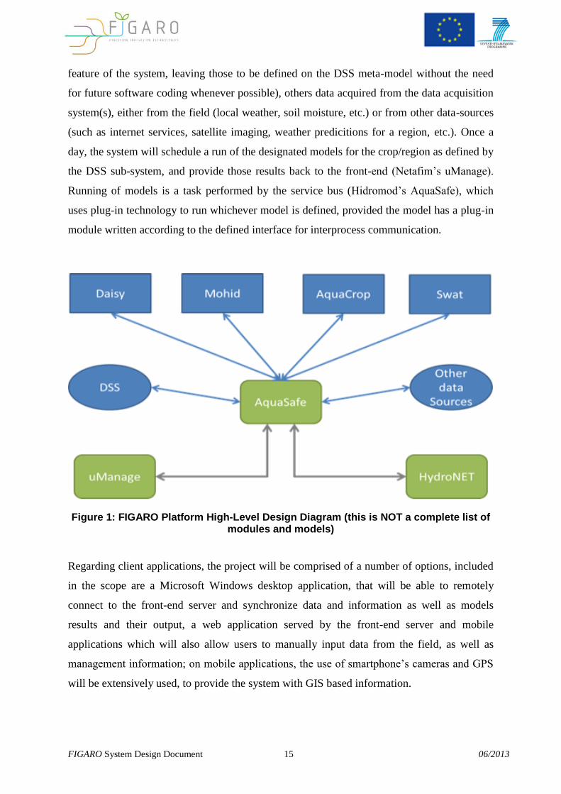
Running of models is a task performed by the service bus (Hidromod’s AquaSafe), which
uses plug-in technology to run whichever model is defined, provided the model has a plug-in
module written according to the defined interface for interprocess communication.
Figure 1: FIGARO Platform High-Level Design Diagram (this is NOT a complete list of modules and models)
Regarding client applications, the project will be comprised of a number of options, included
in the scope are a Microsoft Windows desktop application, that will be able to remotely
connect to the front-end server and synchronize data and information as well as models
results and their output, a web application served by the front-end server and mobile
applications which will also allow users to manually input data from the field, as well as
management information; on mobile applications, the use of smartphone’s cameras and GPS
will be extensively used, to provide the system with GIS based information.
FIGARO System Design Document 16 06/2013
The client applications will allow users to not only get reports on model output and DSS
results, such as simple specific information on optimal irrigation and fertigation scheduling,
but will also allow more advanced users to further delve into results.
Those results can be shown as a simple 7-day instructions (as a weather prediction table seen
on so many applications, web pages and even on TV), containing simple information such as
amount of water to be irrigated on that specific day, predicted weather and so on. Users can,
optionally, show results and partial results in charts and reports, so delving into the specific
predictions and acquired data trends.
Because of the nature of mobile applications, notifications and user pre-defined alarms can be
set to be sent to mobile smartphones in real-time, providing means to not only plan, manage
and improve water productivity, but to correct eventual problems as fast as possible, further
improving waste from operational faults.
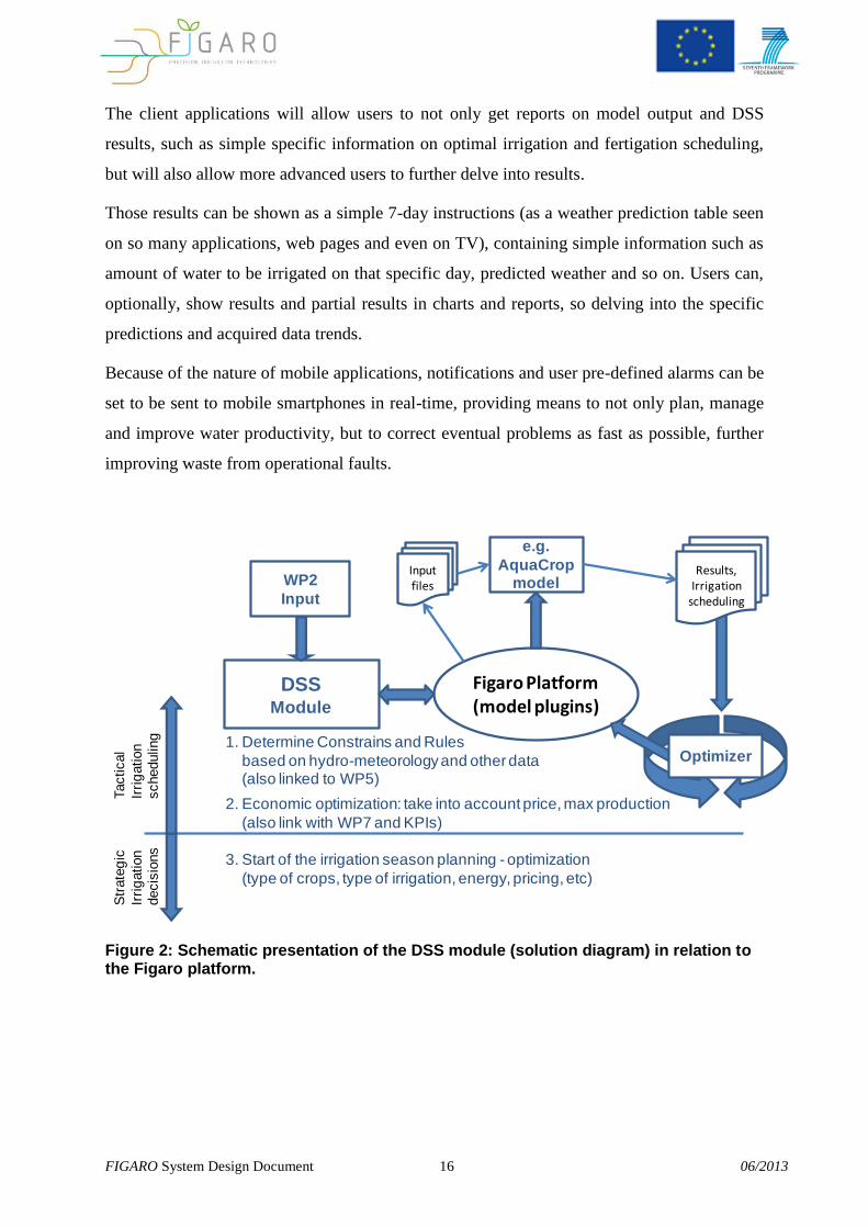
DSSModule
WP2
Input
Figaro Platform(model plugins)
1. Determine Constrains and Rules
based on hydro-meteorology and other data(also linked to WP5)
Str
ate
gic
Irri
gation
decis
ions
Tactical
Irri
gation
scheduling
2. Economic optimization: take into account price, max production
(also link with WP7 and KPIs)
e.g.
AquaCropmodel
Results,Irrigation
scheduling
3. Start of the irrigation season planning - optimization
(type of crops, type of irrigation, energy, pricing, etc)
Input files
Optimizer
Figure 2: Schematic presentation of the DSS module (solution diagram) in relation to the Figaro platform.
FIGARO System Design Document 17 06/2013
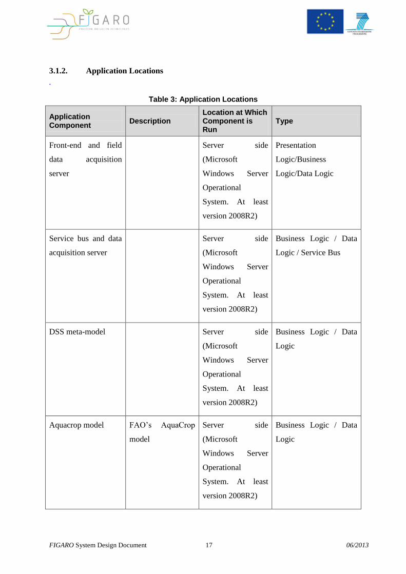
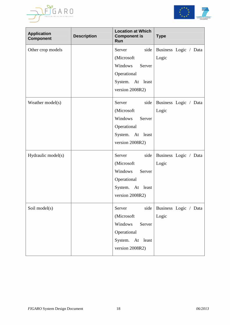
3.1.2. Application Locations
.
Table 3: Application Locations
Application Component
Description Location at Which Component is Run
Type
Front-end and field
data acquisition
server
Server side
(Microsoft
Windows Server
Operational
System. At least
version 2008R2)
Presentation
Logic/Business
Logic/Data Logic
Service bus and data
acquisition server
Server side
(Microsoft
Windows Server
Operational
System. At least
version 2008R2)
Business Logic / Data
Logic / Service Bus
DSS meta-model Server side
(Microsoft
Windows Server
Operational
System. At least
version 2008R2)
Business Logic / Data
Logic
Aquacrop model FAO’s AquaCrop
model
Server side
(Microsoft
Windows Server
Operational
System. At least
version 2008R2)
Business Logic / Data
Logic
FIGARO System Design Document 18 06/2013
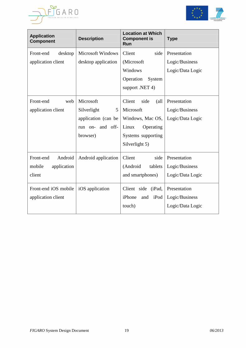
Application Component
Description Location at Which Component is Run
Type
Other crop models Server side
(Microsoft
Windows Server
Operational
System. At least
version 2008R2)
Business Logic / Data
Logic
Weather model(s) Server side
(Microsoft
Windows Server
Operational
System. At least
version 2008R2)
Business Logic / Data
Logic
Hydraulic model(s) Server side
(Microsoft
Windows Server
Operational
System. At least
version 2008R2)
Business Logic / Data
Logic
Soil model(s) Server side
(Microsoft
Windows Server
Operational
System. At least
version 2008R2)
Business Logic / Data
Logic
FIGARO System Design Document 19 06/2013
Application Component
Description Location at Which Component is Run
Type
Front-end desktop
application client
Microsoft Windows
desktop application
Client side
(Microsoft
Windows
Operation System
support .NET 4)
Presentation
Logic/Business
Logic/Data Logic
Front-end web
application client
Microsoft
Silverlight 5
application (can be
run on- and off-
browser)
Client side (all
Microsoft
Windows, Mac OS,
Linux Operating
Systems supporting
Silverlight 5)
Presentation
Logic/Business
Logic/Data Logic
Front-end Android
mobile application
client
Android application Client side
(Android tablets
and smartphones)
Presentation
Logic/Business
Logic/Data Logic
Front-end iOS mobile
application client
iOS application Client side (iPad,
iPhone and iPod
touch)
Presentation
Logic/Business
Logic/Data Logic
FIGARO System Design Document 20 06/2013
3.2. Conceptual Infrastructure Design
The Conceptual Infrastructure Design is a high-level overview of the infrastructure that will
be used to support the application.
Because the system is at an early design stage, it is expected that the information provided
may need to be changed during later design stages or increments.
In general, one server machine is needed to run all server-side components and sub-systems
of the FIGARO platform, although this is scalable to multiple machines in a LAN, including
the proprietary persistency modules for all the sub-systems that may have it.
3.2.1. System Criticality and High Availability
Regarding availability, the system will run on a server or server farm, to provide 24/7 service.
Because of its distributed nature, the system can run any of its modules and sub-systems in its
own machine, even if virtual, or all modules and sub-systems in the same machine. Database
distribution is also an option but out of the scope of this project. The database used by the
data acquisition sub-system is an open-source version of PostgreSql, which offer a number of
readily available open source options for distribution and concurrency. In the scope of this
project, all modules and sub-systems will be run in the same machine, but for an eventual
replication of the server, the option for distributing it is a simple matter of commissioning the
machines and modules, which all allow for distributed run.
Because of its nature of data acquisition, calculations and reporting, this project is not
considered a mission critical one, meaning that down times in the order of 24 hours, although
a set-back, should not badly affect the day-to-day operation of its users and end-customers.
FIGARO System Design Document 21 06/2013
4. Software Design
4.1 Design Strategies
The two main design strategies used in the FIGARO platform are: Service oriented
architecture and Inversion of control. An adaptive portlet design pattern will be used for the
web portal.
This section explains these options in detail.
4.1.1. Service oriented Architecture
SOA can be seen in a continuum, from older concepts of distributed computing (Bell, 2008)
and modular programming, through SOA, and on to current practices of mashups, SaaS, and
cloud computing (which some see as the offspring of SOA) (Watson, 2009).
Service-orientation requires loose coupling of services with operating systems, and other
technologies that underlie applications. SOA separates functions into distinct units, or
services, (Bell, 2008) which developers make accessible over a network in order to allow
users to combine and reuse them in the production of applications. These services and their
corresponding consumers communicate with each other by passing data in a well-defined,
shared format, or by coordinating an activity between two or more services.
This is particularly useful for the FIGARO server. Each component is exposed has a service
(Data Storage and indexing, Data Acquisition, Model Execution, Reporting, Publishing).
This allows for a greater modularity and improves scalability in a cloud environment.
Resource intensive services like model execution or data acquisition can be spread along
multiple servers. Multiple front-ends can consume data produced or indexed by the server by
referring to the appropriate service. The services innards themselves can be replaced as long
as they adhere to the predefined contracts of interaction exposed by their interfaces.
FIGARO System Design Document 22 06/2013
4.1.2. Invertion of control
Inversion of Control (IoC) is an abstract principle describing an aspect of some software
architecture designs in which the flow of control of a system is inverted in comparison to
procedural programming (Caprio, 2005).
In traditional programming the flow of the business logic is controlled by a central piece of
code, which calls reusable subroutines that perform specific functions. Using Inversion of
Control this "central control" design principle is abandoned. The caller's code deals with the
program's execution order, but the business knowledge is encapsulated by the called
subroutines.
In practice, Inversion of Control is a style of software construction where reusable generic
code controls the execution of problem-specific code. It carries the strong connotation that
the reusable code and the problem-specific code are developed independently, which often
results in a single integrated application. Inversion of Control as a design guideline serves the
following purposes:
There is a decoupling of the execution of a certain task from implementation.
Every system can focus on what it is designed for.
The systems make no assumptions about what other systems do or should do.
Replacing systems will have no side effect on other systems.
Inversion of Control is sometimes facetiously referred to as the "Hollywood Principle: Don't
call us, we'll call you", because implementations typically rely on callbacks.
Inversion of control provides extensibility to the FIGARO platform. Well defined interfaces
were designed for data acquisition, transformation, model execution, reporting etc. These
tasks are encapsulated in jobs that manage the information flux, but the details of model
execution, publishing, etc… are contained in the interface implementation.
4.2 Data Storage and indexing
FIGARO System Design Document 23 06/2013
FIGARO server needs to store or index data produced either by the Data Acquisition
components or by Model Executions. Two main types of data are stored:
Time series: data in a single point for a single property along time. For
example data from a temperature sensor on a weather station
Grid data: data on a structure or unstructured grid (1D, 2D or 3D) that varies
in time. For example data from radar images or model results.
Images: Images can be generated form GridData internally by the platform or
from external sources
Time Series will be stored in a database. Grid and images will store metadata in the database
and file on disk.
All Data is only stored for a limited interval in time. Automated backups/purges will be
implemented.
Data and calculation data acquired by the field data acquisition sub-system and the front-end,
namely uManage, is stored in a normalized fashion (where Units of Measurement are the SI
representation of the physical dimension in question). For display, the system has the ability
to convert those numerical results into different units of measurement.
4.3 Data Acquisition from external sources
Data is available in multiple formats (egg: asccii, xls, etc.. for Time Series or HDF5,
NETCDF, GRIB for Grid Data). Multiple protocols can serve data, egg: FTP, http, OPEN
DAP, Sensor Observation Service (SOS).
Some types of data should be downloaded by the platform while others should only be
indexed.
The data acquisition module is responsible for:
Downloading or rebuilding indexes to known data sources
Transform between known formats and the FIGARO platform uses for storage
Indexing the new information in the FIGARO platform data store
All these processes should occur in pre-defined intervals or on-demand.
FIGARO System Design Document 24 06/2013
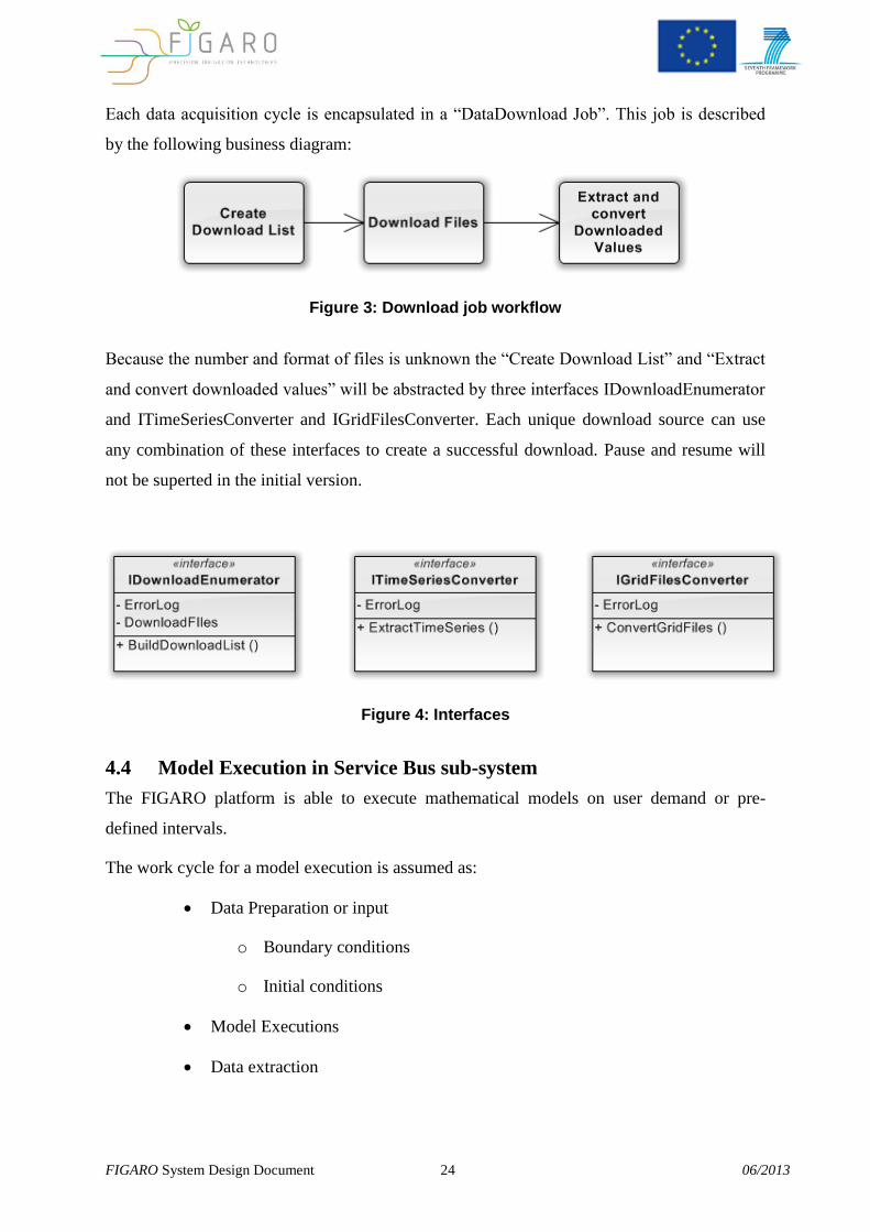
Each data acquisition cycle is encapsulated in a “DataDownload Job”. This job is described
by the following business diagram:
Figure 3: Download job workflow
Because the number and format of files is unknown the “Create Download List” and “Extract
and convert downloaded values” will be abstracted by three interfaces IDownloadEnumerator
and ITimeSeriesConverter and IGridFilesConverter. Each unique download source can use
any combination of these interfaces to create a successful download. Pause and resume will
not be superted in the initial version.
Figure 4: Interfaces
4.4 Model Execution in Service Bus sub-system
The FIGARO platform is able to execute mathematical models on user demand or pre-
defined intervals.
The work cycle for a model execution is assumed as:
Data Preparation or input
o Boundary conditions
o Initial conditions
Model Executions
Data extraction
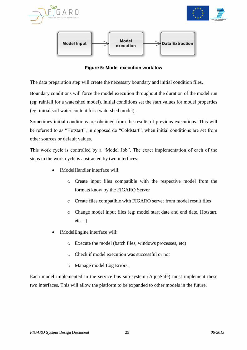
FIGARO System Design Document 25 06/2013
Figure 5: Model execution workflow
The data preparation step will create the necessary boundary and initial condition files.
Boundary conditions will force the model execution throughout the duration of the model run
(eg: rainfall for a watershed model). Initial conditions set the start values for model properties
(eg: initial soil water content for a watershed model).
Sometimes initial conditions are obtained from the results of previous executions. This will
be referred to as “Hotstart”, in opposed do “Coldstart”, when initial conditions are set from
other sources or default values.
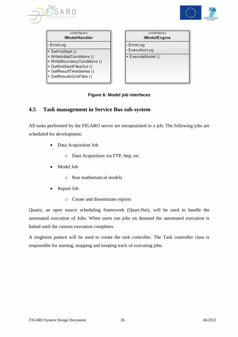
This work cycle is controlled by a “Model Job”. The exact implementation of each of the
steps in the work cycle is abstracted by two interfaces:
IModelHandler interface will:
o Create input files compatible with the respective model from the
formats know by the FIGARO Server
o Create files compatible with FIGARO server from model result files
o Change model input files (eg: model start date and end date, Hotstart,
etc…)
IModelEngine interface will:
o Execute the model (batch files, windows processes, etc)
o Check if model execution was successful or not
o Manage model Log Errors.
Each model implemented in the service bus sub-system (AquaSafe) must implement these
two interfaces. This will allow the platform to be expanded to other models in the future.
FIGARO System Design Document 26 06/2013
Figure 6: Model job interfaces
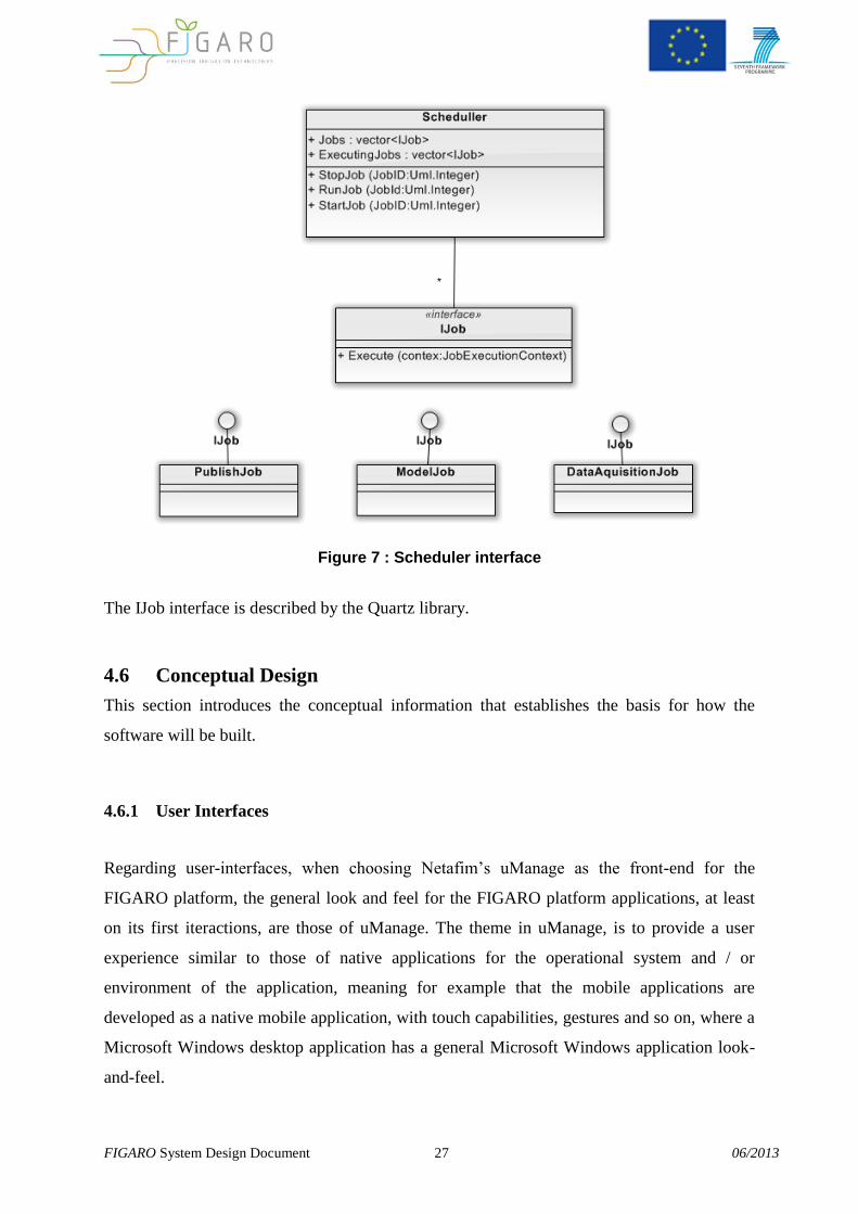
4.5 Task management in Service Bus sub-system
All tasks performed by the FIGARO server are encapsulated in a job. The following jobs are
scheduled for development:
Data Acquisition Job
o Data Acquisition via FTP, http, etc.
Model Job
o Run mathematical models
Report Job
o Create and disseminate reports
Quartz, an open source scheduling framework (Quart.Net), will be used to handle the
automated execution of Jobs. When users run jobs on demand the automated execution is
halted until the custom execution completes.
A singleton pattern will be used to create the task controller. The Task controller class is
responsible for starting, stopping and keeping track of executing jobs.
FIGARO System Design Document 27 06/2013
Figure 7 : Scheduler interface
The IJob interface is described by the Quartz library.
4.6 Conceptual Design
This section introduces the conceptual information that establishes the basis for how the
software will be built.
4.6.1 User Interfaces
Regarding user-interfaces, when choosing Netafim’s uManage as the front-end for the
FIGARO platform, the general look and feel for the FIGARO platform applications, at least
on its first iteractions, are those of uManage. The theme in uManage, is to provide a user
experience similar to those of native applications for the operational system and / or
environment of the application, meaning for example that the mobile applications are
developed as a native mobile application, with touch capabilities, gestures and so on, where a
Microsoft Windows desktop application has a general Microsoft Windows application look-
and-feel.
FIGARO System Design Document 28 06/2013
Being FIGARO an open platform, in the future, anybody that is willing to develop a different
front-end for FIGARO, may do so by implementing the needed interfaces to the service bus
(AquaSafe).
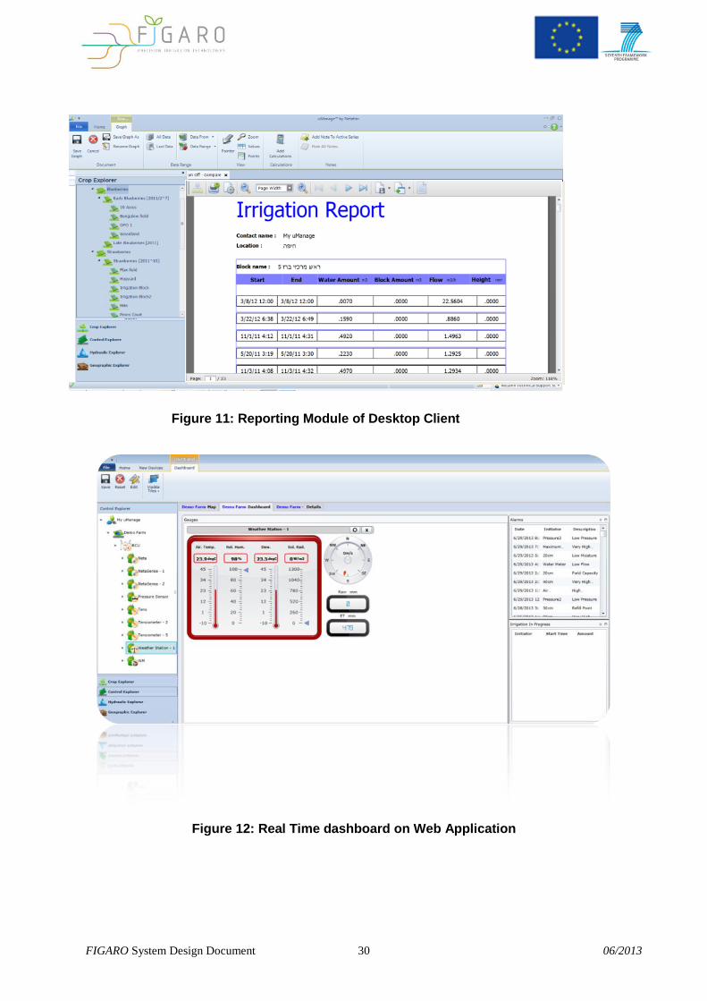
Another benefit of choosing an existing state-of-the-art platform as the front-end sub-system,
is that all features existing in uManage today are available to FIGARO users, including but
not limited to Schedulers, Reports and user customizable Report Templates, Multi-Sensor
Data Fusion Calculations, Text Documents, Charts and Graphs, Notifications and Alarms.
Specific changes needed to the front-end are comprised in the scope of this project and will
be developed as needed throughout the duration of the project.
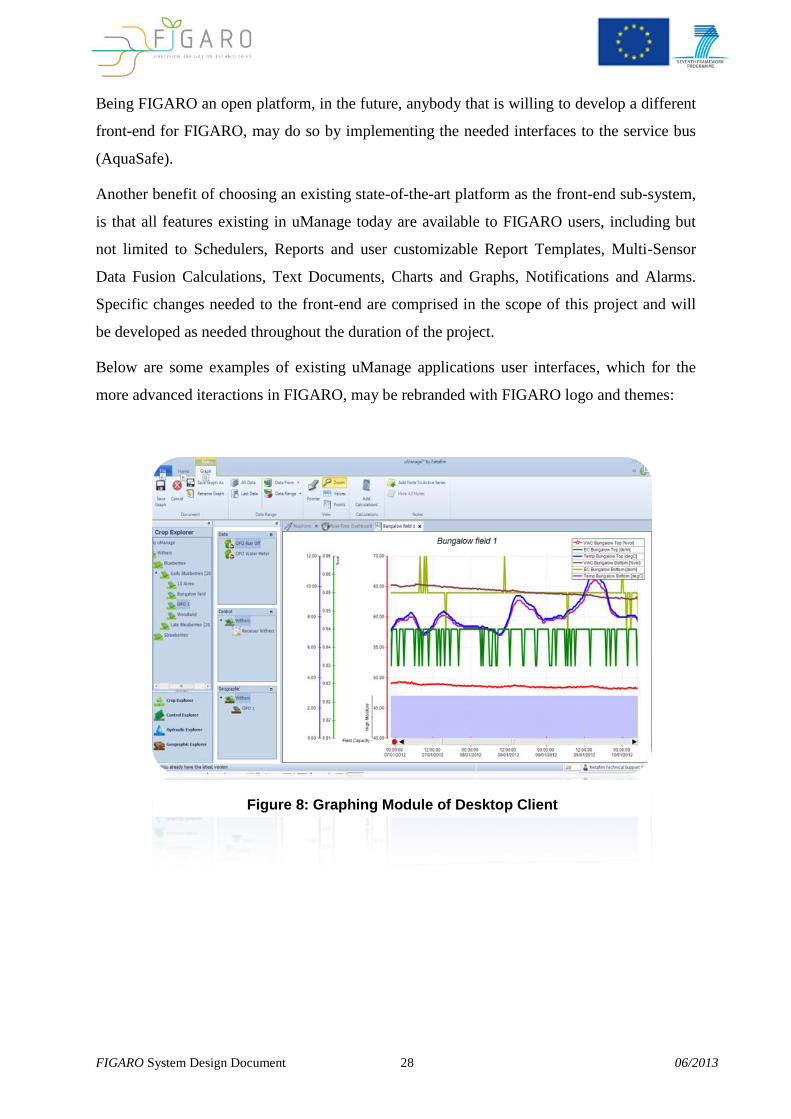
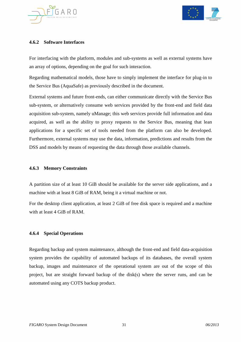
Below are some examples of existing uManage applications user interfaces, which for the
more advanced iteractions in FIGARO, may be rebranded with FIGARO logo and themes:
Figure 8: Graphing Module of Desktop Client
FIGARO System Design Document 29 06/2013
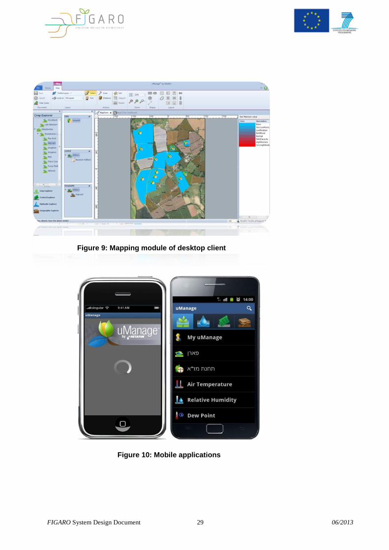
Figure 9: Mapping module of desktop client
Figure 10: Mobile applications
FIGARO System Design Document 30 06/2013
Figure 12: Real Time dashboard on Web Application
Figure 11: Reporting Module of Desktop Client
FIGARO System Design Document 31 06/2013
4.6.2 Software Interfaces
For interfacing with the platform, modules and sub-systems as well as external systems have
an array of options, depending on the goal for such interaction.
Regarding mathematical models, those have to simply implement the interface for plug-in to
the Service Bus (AquaSafe) as previously described in the document.
External systems and future front-ends, can either communicate directly with the Service Bus
sub-system, or alternatively consume web services provided by the front-end and field data
acquisition sub-system, namely uManage; this web services provide full information and data
acquired, as well as the ability to proxy requests to the Service Bus, meaning that lean
applications for a specific set of tools needed from the platform can also be developed.
Furthermore, external systems may use the data, information, predictions and results from the
DSS and models by means of requesting the data through those available channels.
4.6.3 Memory Constraints
A partition size of at least 10 GiB should be available for the server side applications, and a
machine with at least 8 GiB of RAM, being it a virtual machine or not.
For the desktop client application, at least 2 GiB of free disk space is required and a machine
with at least 4 GiB of RAM.
4.6.4 Special Operations
Regarding backup and system maintenance, although the front-end and field data-acquisition
system provides the capability of automated backups of its databases, the overall system
backup, images and maintenance of the operational system are out of the scope of this
project, but are straight forward backup of the disk(s) where the server runs, and can be
automated using any COTS backup product.
FIGARO System Design Document 32 06/2013
5. Software development methodologies
This chapter delineates development and collaboration strategies.
5.1 Agile software development
Agile methodologies are generally accepted as better strategies for most software
development projects when opposed to more “traditional” waterfall approaches.
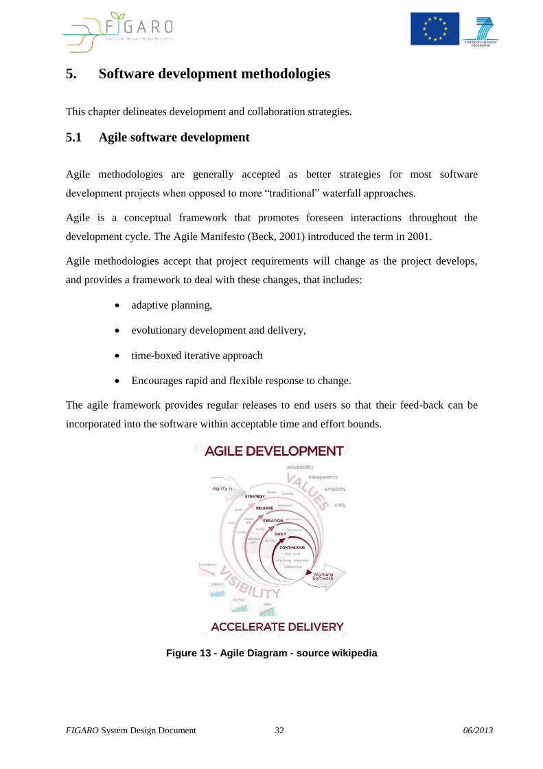
Agile is a conceptual framework that promotes foreseen interactions throughout the
development cycle. The Agile Manifesto (Beck, 2001) introduced the term in 2001.
Agile methodologies accept that project requirements will change as the project develops,
and provides a framework to deal with these changes, that includes:
adaptive planning,
evolutionary development and delivery,
time-boxed iterative approach
Encourages rapid and flexible response to change.
The agile framework provides regular releases to end users so that their feed-back can be
incorporated into the software within acceptable time and effort bounds.
Figure 13 - Agile Diagram - source wikipedia
FIGARO System Design Document 33 06/2013
The twelve principles that underlie the Agile Manifesto, include (Beck, 2001):
1. Customer satisfaction by rapid delivery of useful software
2. Welcome changing requirements, even late in development
3. Working software is delivered frequently (weeks rather than months)
4. Working software is the principal measure of progress
5. Sustainable development, able to maintain a constant pace
6. Close, daily co-operation between business people and developers
7. Face-to-face conversation is the best form of communication (co-location)
8. Projects are built around motivated individuals, who should be trusted
9. Continuous attention to technical excellence and good design
10. Simplicity
11. Self-organizing teams
12. Regular adaptation to changing circumstances
Adapting these principles to the current project needs some adaptations, namely:
1. Customer satisfaction
a. Problem - end users are geographically dispersed and have different interests.
Contact with users is fundamental to deliver useful software.
b. Solution –A member of the consortium will be assigned to each end user. This
member is responsible for presenting and collecting the feed-back for each
iteration from the assigned end user. The development team releases iterations
to these internal members and incorporates the respective feed-back. Once the
consortium members are satisfied with the iteration results they will proceed
with contacts with end users.
2. Working software is delivered frequently (weeks rather than months)
FIGARO System Design Document 34 06/2013
a. Problem – the same problem presented in 1. can lead to delayed user feed-
back.
b. Solution – Have 2 development cycles: one within the consortium where
consortium members test and provide feedback and a longer cycle with
interactions with the “final” end-users.
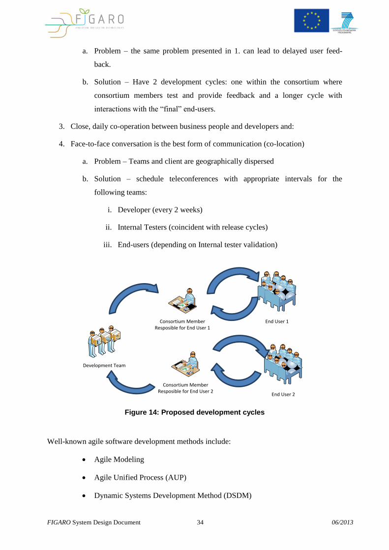
3. Close, daily co-operation between business people and developers and:
4. Face-to-face conversation is the best form of communication (co-location)
a. Problem – Teams and client are geographically dispersed
b. Solution – schedule teleconferences with appropriate intervals for the
following teams:
i. Developer (every 2 weeks)
ii. Internal Testers (coincident with release cycles)
iii. End-users (depending on Internal tester validation)
Consortium MemberResposible for End User 1
Consortium MemberResposible for End User 2
End User 1
End User 2
Development Team
Figure 14: Proposed development cycles
Well-known agile software development methods include:
Agile Modeling
Agile Unified Process (AUP)
Dynamic Systems Development Method (DSDM)
FIGARO System Design Document 35 06/2013
Essential Unified Process (EssUP)
Exia Process (ExP)
Extreme Programming (XP)
Feature Driven Development (FDD)
Open Unified Process (OpenUP)
Scrum
Crystal Clear
Velocity tracking
The scrum methodology was selected for the FIGARO project.
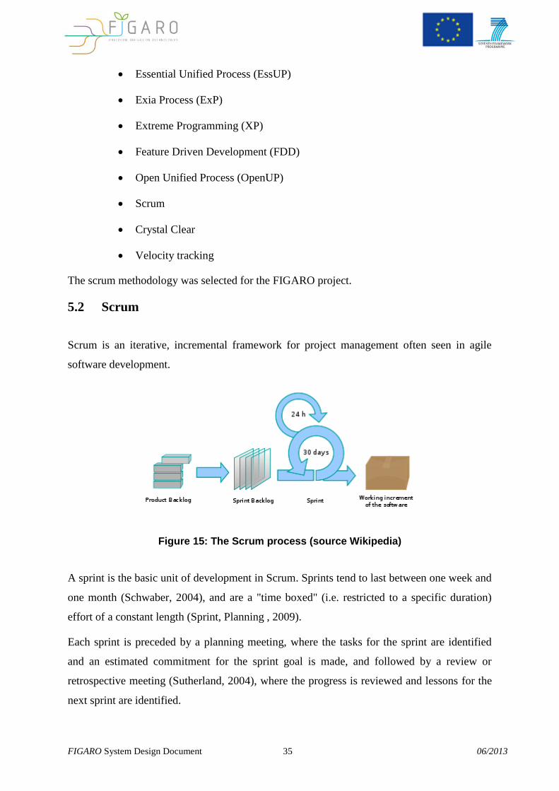
5.2 Scrum
Scrum is an iterative, incremental framework for project management often seen in agile
software development.
Figure 15: The Scrum process (source Wikipedia)
A sprint is the basic unit of development in Scrum. Sprints tend to last between one week and
one month (Schwaber, 2004), and are a "time boxed" (i.e. restricted to a specific duration)
effort of a constant length (Sprint, Planning , 2009).
Each sprint is preceded by a planning meeting, where the tasks for the sprint are identified
and an estimated commitment for the sprint goal is made, and followed by a review or
retrospective meeting (Sutherland, 2004), where the progress is reviewed and lessons for the
next sprint are identified.
FIGARO System Design Document 36 06/2013
During each sprint, the team creates a potentially deliverable product increment (for example,
working and tested software). The set of features that go into a sprint come from the product
“backlog”, which is a prioritized set of high level requirements of work to be done. Which
backlog items go into the sprint is determined during the sprint planning meeting. During this
meeting, the Product Owner informs the team of the items in the product backlog that he or
she wants completed. The team then determines how much of this they can commit to
complete during the next sprint, and records this in the sprint backlog (Schwaber, 2004).
During a sprint, no one is allowed to change the sprint backlog, which means that the
requirements are frozen for that sprint. Development is time boxed such that the sprint must
end on time; if requirements are not completed for any reason they are left out and returned to
the product backlog. After a sprint is completed, the team demonstrates how to use the
software.
Scrum enables the creation of self-organizing teams by encouraging co-location of all team
members, and verbal communication between all team members and disciplines in the
project.
A key principle of Scrum is its recognition that during a project the customers can change
their minds about what they want and need (often called requirements churn), and that
unpredicted challenges cannot be easily addressed in a traditional predictive or planned
manner. As such, Scrum adopts an empirical approach—accepting that the problem cannot be
fully understood or defined, focusing instead on maximizing the team’s ability to deliver
quickly and respond to emerging requirements.
Like other agile development methodologies, Scrum can be implemented through a wide
range of tools. Many companies use universal software tools, such as spreadsheets to build
and maintain artifacts such as the sprint backlog. There are also open-source and proprietary
software packages dedicated to management of products under the Scrum process. Other
organizations implement Scrum without the use of any software tools, and maintain their
artifacts in hard-copy forms such as paper, whiteboards, and sticky notes.
Scrum was selected because it is easily adapted to the restrictions described in the previous
chapter.
FIGARO System Design Document 37 06/2013
6. Testing and Software Quality Assurance
The FIGARO data flow can become quite complex and needs a robust validation
methodology to assure quality Service Cases. This methodology will have three components:
definition of the records specifications;
automatic tests;
internal audits.
The traceability of the data from its origin to the final product represents a valuable quality
assurance procedure. Once major data sets will need to follow complex procedures of
transformation from the original provider to the final product, a procedure that assures that at
any moment it is possible to trace all the operations made to arrive to the result is of prime
relevance.
The validation based on automatic tests will allow the operator to validate in a continuous
way the products being delivered.
The operator can monitor the automatic records generated by the FIGARO platform. The
automatic validation will be based in a specific module developed for the FIGARO platform.
This module will allow the configuration of automatic validation tests that can be applied to
any data set that results from any technical unitary procedure.
This will allow the validation of the data being used and confirm if a specific Service Chain
has consistent values and evolution in time and space. Examples of data validation are:
Min / Max ;
Maximum slope (time and space);
Definition of intervals of validity and detection of erroneous values.
This validation is configured by the FIGARO operator. The internal validation audits will
have two main goals:
FIGARO System Design Document 38 06/2013
Performing the periodical scientific validation of the numerical products. The
idea is to produce a report where the model errors are described and discussed.
The analyzed period must be at least the period between the last audit and the
present one;
Checking the technical integrity of each Service Chain. This consists in
periodical verifications to verify that for usual and extreme predefined
scenarios the whole FIGARO platform has an operational Service Chain.
These validations must be a responsibility of the FIGARO administrator. This task will
produce a Validation manual that will work as a guide for both types of validation
procedures.
6.1 Test Development
The Acceptance Tests are derived using the User Requirements. These requirements will be
grouped into test cases aimed at proving operational functionality, i.e. to demonstrate
operational activities and use cases, as much as possible. This will follow the Specifications
document as much as possible in terms of allocating the requirements to test cases, for clarity,
and because the Specifications already addresses the system from the point of view of its
required functionality.
Test cases will be further split into subgroups depending on whether the requirements
addressed by the test are functional, performance, etc. requirements.
Requirements may be assigned to more than one test case, meaning that all the test steps
addressing that requirement, from each test case must be passed in order for the requirement
to be verified.
Each test case may consist of a different number of requirements to be verified. There is no
strict limit on the number of requirements per test case. However, individual tests will be
limited such that it takes no longer than, say, 1 hour to run a test case.
Hence there is a many-to-many relationship between Requirements and Test Cases; each Test
Case will have many Test Steps; and each Test Step will have one associated Test Procedure
describing the actions to be performed and expected results, to verify the requirement, as
illustrated in the following diagram.
FIGARO System Design Document 39 06/2013
If the requirement implies several different functionalities, in some cases, the requirements
will be broken down in to sub requirements so that they can be assigned to different test cases
for each sub requirement or different test steps within a test.
FIGARO System Design Document 40 06/2013
6.2 Automation
Automation of the tests will be considered as much as possible, balancing the effort of
writing automated tests and developing test tools against effort of design, preparation and
running the tests without automation. At this stage it is already apparent that some aspects
can be tested by automated tests, however until further design is carried out it is not clear
how, or if, in some cases, tests can be automated or to what level.
Automation levels for the tests will be used as follows:
High (H):
Test inputs are fed into the system automatically, e.g. from a simulator or a script. Outputs
and actions resulting from the test inputs (including logs) are automatically analysed and the
test output is simply a Fail, a Qualified Pass or a Pass which then has to be acknowledged by
a tester.
Medium (M):
(MI) Test inputs are fed into the system automatically. Outputs and actions resulting from the
test inputs are manually evaluated by the testers.
or
(MO) Test inputs are fed manually into the system, the outputs and actions arising from the
inputs are automatically analysed to give the test result
Low (L):
Test inputs are entered manually into the system and the results are judged manually by the
tester.
The development of the test cases will continue through the development phase, as more
information and clarity of the design and implementation of the system is established. The
final fine details of test procedures (such as “buttons” to select) can only be completed when
the SW is written and integrated.
FIGARO System Design Document 41 06/2013
6.3 Functional Testing
Functional testing will apply to the majority of individual requirements. They demonstrate
that the system has the capability of performing various tasks and do not specify performance
values for these tasks. They can be performed in relative isolation of the background loading
of the system and do not require other unrelated (e.g. automated) activities to be going on in
the background.
Some functional tests apply to very manual activities whereas some apply to automated
activities and hence need to be verified by first setting up nominal automated activities in the
system.
6.4 Performance Testing
There are some requirements in the Specifications on the required performance of the system.
The requirements are identified as having quantitative values associated with an action.
Although not stated in the Specification, it is assumed that these requirements are required to
be fulfilled under “nominal” operational conditions. Hence “nominal” operational conditions
needs to be defined, and is generally assumed to be where the system is under lighter loading
conditions than is specified for the load testing. The “nominal scenario” is discussed below.
These performance requirements will be verified while the system is experiencing its nominal
loading of systematic activities, such as ETL of data providers WebServices, portal use for 10
users in concurrent usage, etc.
It is estimated that the system will need to run for 24 hours in nominal conditions for these
performance requirements and functional tests on systematic functions to be carried out. The
length of this time period is chosen
to provide a nominal system during the course of performance testing
to provide a period which adequately accommodates any major periodic
activities experienced by the system (such as the ETL for the WebServices of
the data providers).
FIGARO System Design Document 42 06/2013
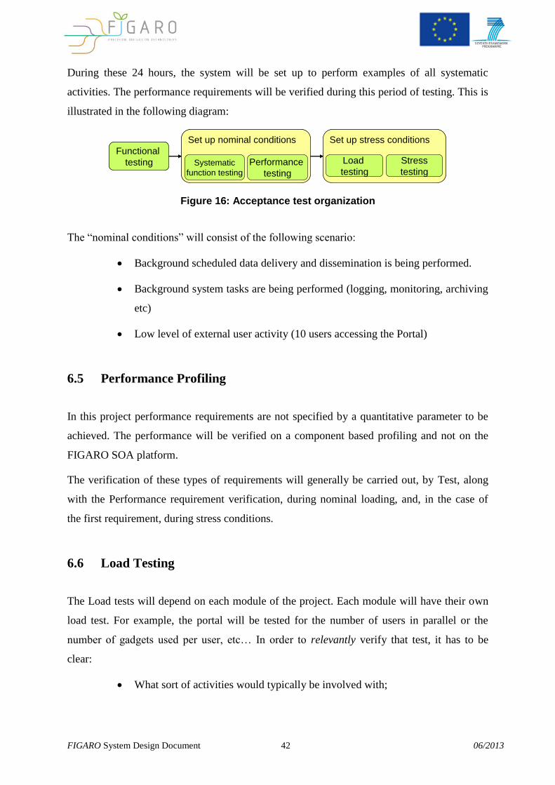
During these 24 hours, the system will be set up to perform examples of all systematic
activities. The performance requirements will be verified during this period of testing. This is
illustrated in the following diagram:
Functional
testing
Set up nominal conditions
Systematic
function testing
Set up stress conditions
Load
testingPerformance
testing
Stress
testing
Functional
testing
Set up nominal conditions
Systematic
function testing
Set up stress conditions
Load
testingPerformance
testing
Stress
testing
Figure 16: Acceptance test organization
The “nominal conditions” will consist of the following scenario:
Background scheduled data delivery and dissemination is being performed.
Background system tasks are being performed (logging, monitoring, archiving
etc)
Low level of external user activity (10 users accessing the Portal)
6.5 Performance Profiling
In this project performance requirements are not specified by a quantitative parameter to be
achieved. The performance will be verified on a component based profiling and not on the
FIGARO SOA platform.
The verification of these types of requirements will generally be carried out, by Test, along
with the Performance requirement verification, during nominal loading, and, in the case of
the first requirement, during stress conditions.
6.6 Load Testing
The Load tests will depend on each module of the project. Each module will have their own
load test. For example, the portal will be tested for the number of users in parallel or the
number of gadgets used per user, etc… In order to relevantly verify that test, it has to be
clear:
What sort of activities would typically be involved with;
FIGARO System Design Document 43 06/2013
What system resources they would be using (storage, link loading, memory,
processing…), and hence;
Where the real bottlenecks of the system can occur.
With such variety of activities taking place in parallel in the system, it is difficult to predict
problems which may occur at full usage so the most convincing way to demonstrate the
system’s capability is to actually load the system with a representative scenario of this many
users performing a variety of tasks.
6.7 Stress Tests
Stress tests are those that expose the system to unusually high levels of activity in order to
either characterize how the system behaves or to verify that if the system cannot cope
nominally then it does so gracefully and in a recoverable fashion
Stress tests will be carried out at the end of load testing. The verification of the requirement
above will involve a review of the system performance during the load test (including the
ramping–up of the load test) and an analysis of where perceived bottlenecks in the system
may evolve and the consequences.
6.8 Test Tools and Simulators
In order to set both the Nominal and Stress conditions running on the system, all external
interacting bodies need to be simulated to varying degrees if the actually external bodies are
unavailable at the time of the tests.
The tools and simulators to consider:
Web Capacity Analysis Tool (WCAT) is a lightweight HTTP load
generation tool primarily designed to measure the performance of a web server
within a controlled environment. WCAT can simulate thousands of
concurrent users making requests to a single web site or multiple web sites.
The WCAT engine uses a simple script to define the set of HTTP requests to
be played back to the web server. Extensibility is provided through plug-in
DLLs and a standard, simple API.
FIGARO System Design Document 44 06/2013
LoadImpact
Performance Monitor
SQL Profiler
soap UI - soapUI is a tool for functional testing, mainly of Web Services like
SOAP based Web Services and REST Web Services, but also HTTP based
services and JMS Services as well as databases. soapUI is an Open Source
tool.
6.9 Test Equipment
Currently identified test hardware that will be used includes the following. This list will be
expanded upon and scoped during the next project phases:
Computers to support the load testing;
Computers to access and test the portal;
Phones to receive SMSs;
SmartPhones to test mobile applications.
FIGARO System Design Document 45 06/2013
6.10 Test Data
Test data will be generated before the tests are performed and will be “representative enough”
to allow the acceptance tests to be performed. This means they must contain the expected
values for the test they are being used in where those parameters are necessary for the correct
running of the test.
For example, for Data Providers WebServices, it may be necessary to provide the sample data
to be integrated on the Business Intelligence engine. For testing, the data can be provided
with CSV files to the BI engine.
To test the WebServices, the first version available can be mocked up. This way the
interfaces can be tested and adjusted, although the data will have to be tested later, when
available.
The process of defining the test data has begun with the requirements analysis and will
continue through the next phase of the project.
6.11 Regression Tests
When possible, regression tests must be available. The largest proportion of verification
activities at Test Phase will be by Test (T). For various reasons, for example the failure of a
test or the introduction of a new requirement, various tests may need to be repeated.
If a test step fails during a run of the test, a software problem report will be raised and an
assessment will be carried out as to the cause of the failure, whether it is a software problem,
configuration problem, a test procedure error, etc.
Once the problem is resolved, a further assessment will be made as to which, if any,
previously-run tests have been affected by the solution, and these tests will be run again. This
may result in
the re-running of a whole test case
the re-running of one or more test steps
the writing of a new test case and running of that new test case
Which of the above is most appropriate will be done on a case-by-case basis.
FIGARO System Design Document 46 06/2013
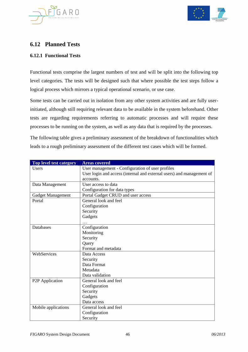
6.12 Planned Tests
6.12.1 Functional Tests
Functional tests comprise the largest numbers of test and will be split into the following top
level categories. The tests will be designed such that where possible the test steps follow a
logical process which mirrors a typical operational scenario, or use case.
Some tests can be carried out in isolation from any other system activities and are fully user-
initiated, although still requiring relevant data to be available in the system beforehand. Other
tests are regarding requirements referring to automatic processes and will require these
processes to be running on the system, as well as any data that is required by the processes.
The following table gives a preliminary assessment of the breakdown of functionalities which
leads to a rough preliminary assessment of the different test cases which will be formed.
Top level test category Areas covered
Users User management - Configuration of user profiles
User login and access (internal and external users) and management of
accounts.
Data Management User access to data
Configuration for data types
Gadget Management Portal Gadget CRUD and user access
Portal General look and feel
Configuration
Security
Gadgets
…
Databases Configuration
Monitoring
Security
Query
Format and metadata
WebServices Data Access
Security
Data Format
Metadata
Data validation
P2P Application General look and feel
Configuration
Security
Gadgets
Data access
Mobile applications General look and feel
Configuration
Security
FIGARO System Design Document 47 06/2013
Top level test category Areas covered
Gadgets
Data access
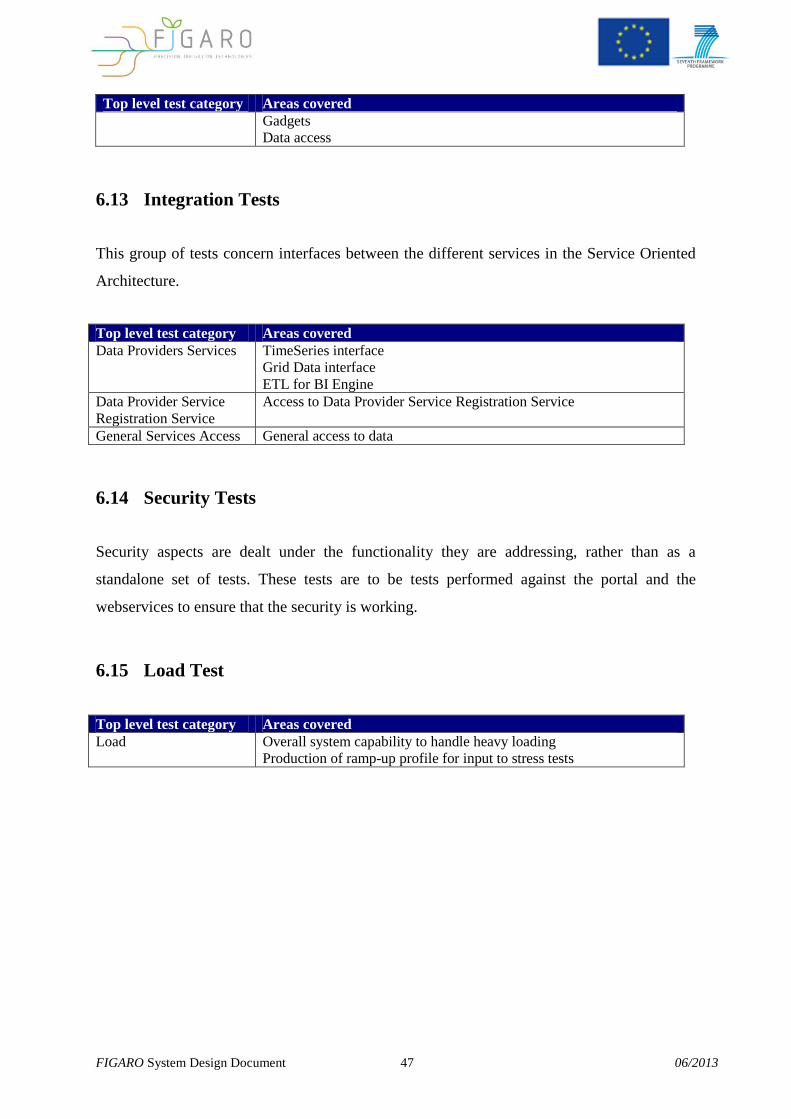
6.13 Integration Tests
This group of tests concern interfaces between the different services in the Service Oriented
Architecture.
Top level test category Areas covered
Data Providers Services TimeSeries interface
Grid Data interface
ETL for BI Engine
Data Provider Service
Registration Service
Access to Data Provider Service Registration Service
General Services Access General access to data
6.14 Security Tests
Security aspects are dealt under the functionality they are addressing, rather than as a
standalone set of tests. These tests are to be tests performed against the portal and the
webservices to ensure that the security is working.
6.15 Load Test
Top level test category Areas covered
Load Overall system capability to handle heavy loading
Production of ramp-up profile for input to stress tests
FIGARO System Design Document 48 06/2013
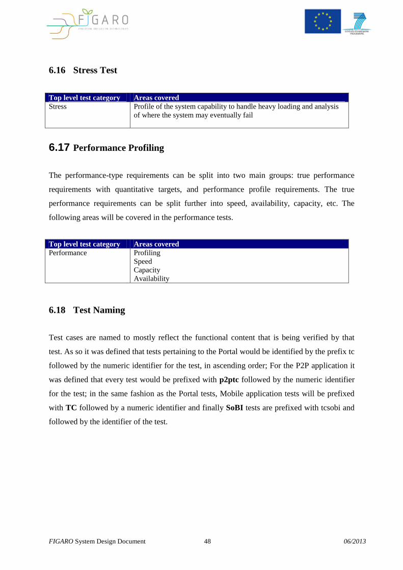
6.16 Stress Test
Top level test category Areas covered
Stress Profile of the system capability to handle heavy loading and analysis
of where the system may eventually fail
6.17 Performance Profiling
The performance-type requirements can be split into two main groups: true performance
requirements with quantitative targets, and performance profile requirements. The true
performance requirements can be split further into speed, availability, capacity, etc. The
following areas will be covered in the performance tests.
Top level test category Areas covered
Performance Profiling
Speed
Capacity
Availability
6.18 Test Naming
Test cases are named to mostly reflect the functional content that is being verified by that
test. As so it was defined that tests pertaining to the Portal would be identified by the prefix tc
followed by the numeric identifier for the test, in ascending order; For the P2P application it
was defined that every test would be prefixed with p2ptc followed by the numeric identifier
for the test; in the same fashion as the Portal tests, Mobile application tests will be prefixed
with TC followed by a numeric identifier and finally SoBI tests are prefixed with tcsobi and
followed by the identifier of the test.
FIGARO System Design Document 49 06/2013
A. Additional Information
A.1. Packaging and Installation
Regarding the platform server(s) and server-side components, each module has to be installed
separately, although all will be available as one big archive containing installation files for all
required components. Optional components will be made available when existant from the
FIGARO website as well.
Client side desktop application has its own installation file for Microsoft Windows
operational systems. Web application doesn’t need to be installed, and is ran on a browser
(specific browser requirements specified in the relevant section of this document).
Mobile applications for Android and iOS devices will be made available free of charge on the
relevant official application stores.

FIGARO System Design Document 50 06/2013
- END -