flc based fault tolerant technique in dc-dc converters for ... · fd is a mandatory stage in any...
TRANSCRIPT
* EEE Department, Sathyabama University, Chennai, India, Email: [email protected]
** EEE Department, Sathyabama University, Chennai, India, Email: [email protected]
FLC Based Fault Tolerant Technique inDc-Dc Converters for PV SystemP. Vijay Kumar* and G. Nagarajan**
Abstract: The pvtechnology is the most promising alternative technology in now a days. Dc-Dc converters playa major role in pv system. Some of the converters have an enhanced fault tolerant capacity. But oc and sc faultscan cause ripples in case of over load. We have to improve the reliability of power converters. In this paper I amproposing fuzzy based fault tolerant (FT) scheme for three level boost converter. FT can achieve in two steps.Fault diagnostic and fault control method. FD is a mandatory stage in any semiconductor switches. For FT weneed some additional components to the converter. To validate this we are using a resistive load circuit. Theexperimental results are given to verify the validity of analysis.practically it is applicable for battery chargingpurpose.
Keywords: PV system, Dc-Dc converter, FT, FD.
1. INTRODUCTION
Environmental concern and availability point of view are the main issues for introducing Renewable EnergySource (RES) in energy domain. Such applications are small size applications and large power applications.The main attractive features of RES are continuous availability, non-pollution energy production and naturallyreplenishing. Based on this features now a days it is the most promising alternative energy source.Photovoltaic (PV) technology is completely differ from all other technologies (Wind, Hydro, etc) in someaspects like stability, wide power range, withstand for all climatic conditions, modularity and low maintenancesmall size application are calculator,water pumps and traffic lights. Powerplants and electrification forremote areas are some of High power applications of PV technology [1]. PV modules are famous for highreliability and long life time [1]. PV systems contribute with help of power controlling and energy storagedevices [2]. We know that power electronic converters are the most sensitive devices [3]. Reliability is themain obstacle for extensive applications. Main issues are technical problems as well as MPPT, islandingand also the design prospect also [4].
PV systems are mainly three types. Standalone PV systems, Grid connected system and Hybrid PVsystems. DC-DCpower converters are play a vital role in all these PV systems for conditioning the powerwhich was generated by pv panel. A failure of DC-DC converter may lead to the total system failure. Thetwo most crucial components in power converters are Aluminum electrotype capacitors and semiconductorswitches. Failure in capacitors may lead to more than 50% malfunctions and breakdown. Semiconductorfailures may cause 34% in power devices.[5].Inmany power applications mostly failure components arecapacitors and power switches.Because of high mechanical stress and thermal stress [7].
The main reason for failure of power switches is an excess of electrical stress and thermal stress. [8].the most common failures in power switches are Short circuit faults, Open circuit faults, and Gating faults.These may happen based on following external or internalreasons example 1) incorrect gate voltages 2)Failure of the drives 3) Switchingrupturewhichcanbeaconsequence of an SC fault 4) Over electrical stress
I J C T A, 8(5), 2015, pp. 1831-1842© International Science Press

1832 P. Vijay Kumar and G. Nagarajan
In general open circuit faults (OCF) are consequence of short circuit faults (SCF) are gating faults inthis paper we are considering the both SC and OC faults. Many surveys have been presented in literaturereport on FD of aluminum electrotype capacitors for different applications [9]. in power converters forsome critical applications to improve the reliability fault tolerant operation is mandatory step. FT canachieve in two ways. Fault diagnosis (FD), fault control method. FD method gives suitable response to thefault which occurs in power switch. FD achieve in two stages fault detection and identification.
Several methods are proposed for FT and FD for SC and OC faults [10]. For isolated phase shifted full-bridge dc-dc converters switch faults diagnosis with FT scheme was proposed in [11].In this transformerprimary voltage used as diagnosis criteria. For hybrid electric vehicles an OCF detection method waspresented based on comparing the duty cycle with the inductor current slope [5]. For a Unidirectionalpower flow boost interleaved DC-DC converter an OCF diagnosis method was presented in [13]. For H-bridge dc-dc converter an FT scheme was illustrated with help of redundancy [14] for this extra leg and abidirectional selector switch are combined to the existing circuit. By the help of magnetic componentvoltage a FD method was discussed for PWM dc-dc converter. In this method we measure the inductorvoltage by using an auxiliary winding in magnetic core [15]. In [16] a ED method was discussed forMOSFETfaults in (Zero Voltage Switch) ZVS dc-dc converter at the initial stage. The main drawback ofthis method is it does not stops the faults during DC-DC converter. It works by the help of integral and peakvalues of DC link current. For two cascaded buck non isolated converters an OCF method was presented in[17] in this we use the measured output voltage and current at the source and load converters. Differenttypes of diagnostic methods for isolated converter topologies were discussed in [18]. Any one of the isolatedDC-DC converter topologies can be applicable for PV system, eventhough their pulsed input current mightbe harmful for lifetime of PV module [19]. The above mentioned topologies are deals with only opencircuit faults only. In [20] we discussed an single switch DC-DC converter with fault tolerant capabilityunder OC and SC switch failures. For this we are using field programmable gate array (FPGA) no additionalsensors are required for this method. Among all those methods three level boost converter has an advantagethat it can double the voltage gain of the conventional two-level non-isolated topologies, while the powerconverter switch voltage stress is half [21]. Because of this noise, conduction losses and switching lossesare reduce.Three level non isolated converters are used in high power rating pv systems with high voltagegain require to maintain constant dc bus voltage. Features of three level boost converters are reduced inputfilter size, current ripple cancellation and the switching device voltage is half of the output voltage.so thepower density and effectiveness will increase. A two level version of the boost converter will be very
Figure 1: Three level boost converter with fuzzy control technique

FLC Based Fault Tolerant Technique in Dc-Dc Converters for PV System 1833
simple, efficient and will have less number of components. In this the inductor loading stage is dividinginto half.
This paperillustrates a new topology for three level boostconvertersto prevent faults which occur inpower semiconductor switches. a fault tolerant technique also proposed with the help of fuzzy controltechnique. Fuzzy control is an artificial intelligent control technique. It offers a soft computation. It hasfaster and smoother response fuzzy control is suitable for approximation reasoning. For this technique weneed some more additional components to the existing converter. A brief explanation of thepv system andoperation process is given in sections[2]below. The FT and FD methods are discussed in sections[IV&V].The validity of verified analysis is discussed with the help of experimental results in section [VIII].
2. PHOTOVOLTAIC SYSTEM
In photovoltaic system we will discuss in two parts. Overview and Configuration.
2.1. Overview
Power In photovoltaic system electricity generates directly from sun light by the help of solar cells. Theprocess of generating electricity in solar cell based on the principle of “PHOTOELECTRIC EFFECT” itdirectly converts solar energy into electric.
To form a solar array numbers of solar cells are connected in series or parallel. When solar arrayexposed to sun dc voltage will produce. The equivalent circuit of solar cell is displayed below in generalsolar cell can be treated as a nonlinear current source. The factors which are effect the generating currentare characteristic of material, irradiation, life time of solar cell and climatic conditions.
Figure 2: Equivalent circuit of solar panel
2.2. Configuration
Thepv system which shown in fig (1) is based on conventional three level boost converter. Three level converterswill give efficient high voltage and high output for pvapplications [22]. When compared to conventionaltopology proposed scheme needs an additional extra component [1]. For application of proposed fault tolerantDc-Dc converter topology the examples of possible combinations are1.Series-parallel2.parallel-series
Conventional topologytakes the total input current and total voltage of whole pv array. Whereas theproposed FT topology needs an extra two sensors for measure input voltage and current of each division ofpv module both topologies are required voltage sensors at output capacitor for balancing dc capacitor linkvoltage proposed system needs an TRIAC also. In case of fault occur only TRIAC will trigger
3. NOMENCLATURE
io = Saturation current Ipv = Light induced current
Voc = open circuit voltage Isc = short circuit current
1834 P. Vijay Kumar and G. Nagarajan
Vsc = short circuit voltage q = Electroncharge (1.60217* � 10� – 23c)
a = diode ideality constant K = Boltzmannconstant (1.380 � 10–23j/k)
T = cell temperature (in KELVIN)
3.1. Operation Process
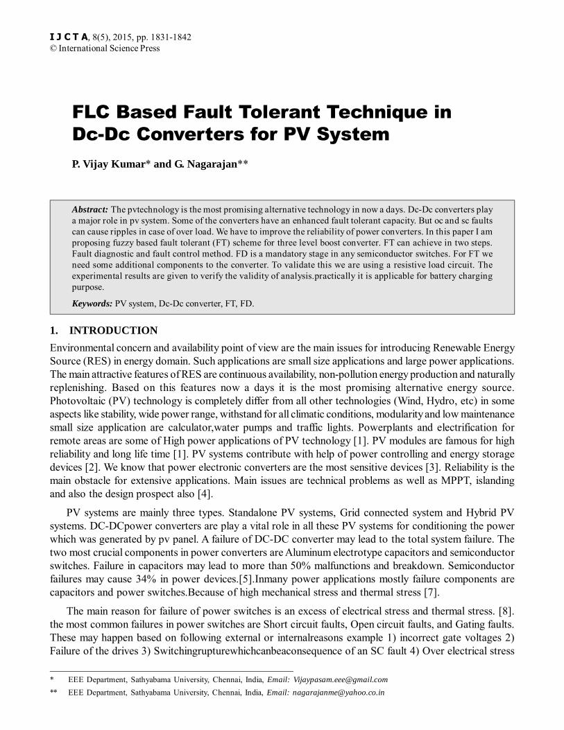
In normal state condition the topologies behaves as similar to conventional topology. In this power switchS1 used to control the current power switch S2 used for voltage control DC link capacitor. S1 maintain byMPPT [PAO] method which illustrated in [23]. It use the total array output voltage (sum of Vpv1, Vpv2),andone ofthe current (Ipv1, Ipv2).the entire process shownin fig (3).
Figure 3: Fault Tolerant Control during Normal State
Total circuit analyzed in three states1.Normal State [w/o fault],Faulty State, Reconfigure State
3.2. Normal State
Normal operation is described by the help of power switch conduction modes. There are three modes ofoperation.1. Both switches on 2. Any one switchOn/Off 3. Both switches offthe entire process is describedas three level boost converters [24].
3.3. Faulty State
Whenever the fault occurs in any one of power switches the converter will stop working. Before that atransient state will occur and then it stopped. When fault occur in one switch other will get an impulse toconduct until conductor will stop. In case of faulty state two modes are possible.1. Both switches are OFF2. Any one switches OFF.
3.4. Both Switches Off
During this period both diodes D1 and D2 are in reverse bias and starts conduction. Then both capacitorsC1 and C2 are gets charging. The analysis equations are
1 1 1dil
Vpv L Vcdt
� � (1)
2 2 2dil
Vpv L Vcdt
� � (2)
Add eqns 1 & 2
FLC Based Fault Tolerant Technique in Dc-Dc Converters for PV System 1835
1dvci
C io iLdt
� � (3)
22
dvcC io iL
dt� � (4)
3.5. One Switch Off
During this period Diode D1 is reverse bias and D2 in conduction mode capacitor C1 gets charging withcurrent is [iL]& capacitor C2 discharge with current Io
� �1 2 1 2 2diL
Vpv Vpv L L Vcdt
� � � �
1dVci
C io iLdt
� � (5)
2
2 0dVc
C iodt
� � (6)
When the fault occurs in switch S2 then C2 gets charge with current C1 gets discharge with currentio.Whenshort circuit fault occur in any one of the switch converter, the voltage of that particular converteris zero Vsc = 0
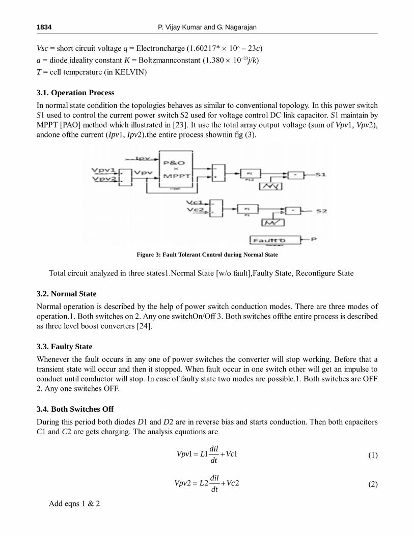
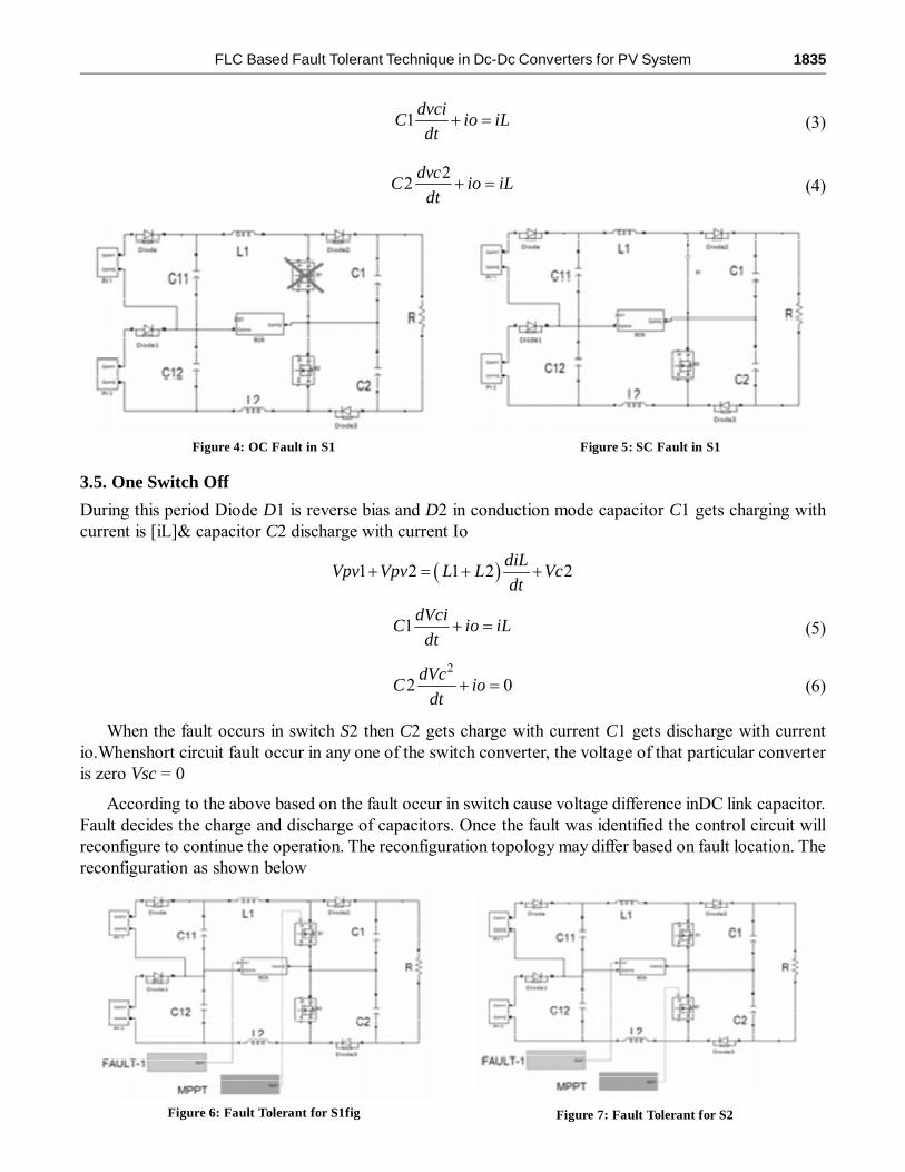
According to the above based on the fault occur in switch cause voltage difference inDC link capacitor.Fault decides the charge and discharge of capacitors. Once the fault was identified the control circuit willreconfigure to continue the operation. The reconfiguration topology may differ based on fault location. Thereconfiguration as shown below
Figure 4: OC Fault in S1 Figure 5: SC Fault in S1
Figure 6: Fault Tolerant for S1fig Figure 7: Fault Tolerant for S2
1836 P. Vijay Kumar and G. Nagarajan
4. FAULT DIAGNOSTIC METHOD
Before analyzing the circuit let us made some assumptions (1). All elements are ideal 2. Voltage constant
In the convention three level boost converter control variables are input current,input voltage and outputdc link capacitor voltage. Thepv array mainly affected by atmospheric conditions. Such asclouds,temperature,irradiation etc.The FD method which is used must be robust and highly reliable.Basedon V-I characteristics of pv cell the effect of temperature and irradiation on pv module can be mathematicallypresented [25].
I = Ipv – Io {exp(qV|aKT) – 1} (7)
Series and shunt resistor losses are not influence the temperature and radiation effect on pv cell. So wewere not taking into consideration [26].
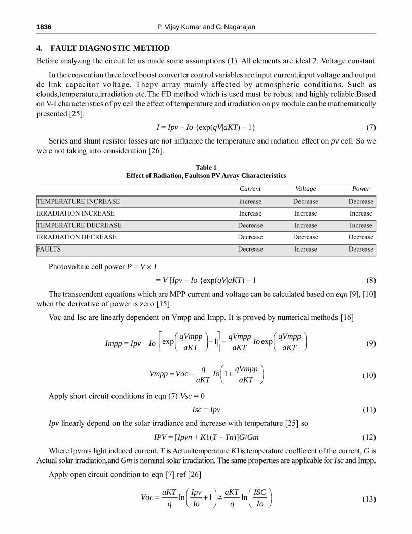
Table 1Effect of Radiation, Faultson PV Array Characteristics
Current Voltage Power
TEMPERATURE INCREASE increase Decrease Decrease
IRRADIATION INCREASE Increase Increase Increase
TEMPERATURE DECREASE Decrease Increase Increase
IRRADIATION DECREASE Decrease Decrease Decrease
FAULTS Decrease Increase Decrease
Photovoltaic cell power P = V � I
= V [Ipv – Io {exp(qV|aKT) – 1 (8)
The transcendent equations which are MPP current and voltage can be calculated based on eqn [9], [10]when the derivative of power is zero [15].
Voc and Isc are linearly dependent on Vmpp and Impp. It is proved by numerical methods [16]
Impp = Ipv – Io exp 1 expqVmpp qVmpp qVmpp
IoaKT aKT aKT
� �� � � �� �� � � �� �� � � �� �(9)
1q qVmpp
Vmpp Voc IoaKT aKT
� �� � �� �� �
(10)
Apply short circuit conditions in eqn (7) Vsc = 0
Isc = Ipv (11)
Ipv linearly depend on the solar irradiance and increase with temperature [25] so
IPV = [Ipvn + K1(T – Tn)]G/Gm (12)
Where Ipvmis light induced current, T is Actualtemperature K1is temperature coefficient of the current, G isActual solar irradiation,and Gm is nominal solar irradiation. The same properties are applicable for Isc and Impp.
Apply open circuit condition to eqn [7] ref [26]
ln 1 lnaKT Ipv aKT ISC
Vocq Io q Io
� � � �� � �� � � �� � � �
(13)

FLC Based Fault Tolerant Technique in Dc-Dc Converters for PV System 1837
Based on above equation we know that Voc logarithmically depends on short circuit current. To studythe effect of temperature on open circuit voltage Voc, substitute Io in eqn (13)
Io = BTrexpEGO
KT� ��� �� �
(14)
Where B and r are temperature independent constants and EG0 is the band gap extrapolated to theabsolute zero the temperature effect on short circuit current is very small and can be neglected.
Based on the properties of voltage and current of pv cell, the changes in maximum power will easilyidentified. During a fault the current and power are suddenly drop but the voltage will increase. The filterdesign by using a first order low pass filters with a frequency of 0.5Hz to 1Hz.
Fault detection can be applied any of DC converter for controlling purpose. Because in any powerconverter open circuit fault will lead to control failure and short circuit fault will lead to zero voltage.
Figure 8: Fault Diagnostic Method
After detecting the fault we have to locate it. In this topology we have two power switches. To locatethe fault a fault diagnostic variable can be created by comparing the two output DC link capacitor voltages.
F = Vc1 – Vc2 (16)
If F is bigger than positive threshold K then the fault occurs in switch S1. If F is smaller than a negativethreshold –k then fault occur in switch S2.This threshold was empirically chosen during tested. The totaldiagnostic method is presented in above Fig (8).
5. RECONFIGURATION METHOD
After detecting the fault and identified the faulty switch the system will reconfigure for further operations.The total control topology is discussed in below Fig. In normal state the three level boost converter uses thetotal output current and voltage. The output DC link capacitor voltage is used to balance it. During normalmode of operation in two switches S1 used to mppt control and switch S2 is used to balance the DC linkcapacitor voltage.The reconfiguration topology is as shown below Fig (9)
Once fault detection over the control system operate in different way, based on fault location occur inpower switch S1 or power switch S2. When fault occur in power converter one of the switches stop working.Now the three level boost converter reconfigure into two level boost converter with mppt control. In thiscase mppt control the half of the module array only. So after the fault occurrence also the converter does notstop working, but it provides less power.
1838 P. Vijay Kumar and G. Nagarajan
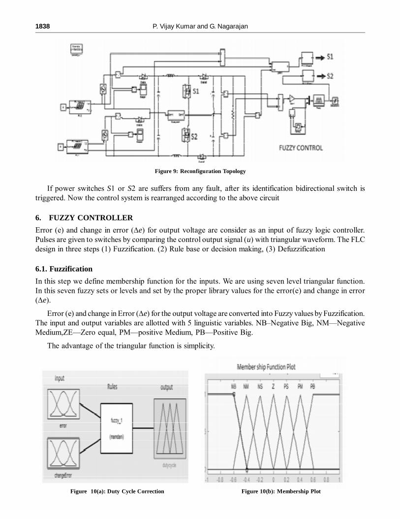
If power switches S1 or S2 are suffers from any fault, after its identification bidirectional switch istriggered. Now the control system is rearranged according to the above circuit
6. FUZZY CONTROLLER
Error (e) and change in error (�e) for output voltage are consider as an input of fuzzy logic controller.Pulses are given to switches by comparing the control output signal (u) with triangular waveform. The FLCdesign in three steps (1) Fuzzification. (2) Rule base or decision making, (3) Defuzzification
6.1. Fuzzification
In this step we define membership function for the inputs. We are using seven level triangular function.In this seven fuzzy sets or levels and set by the proper library values for the error(e) and change in error(�e).
Error (e) and change in Error (�e) for the output voltage are converted into Fuzzy values by Fuzzification.The input and output variables are allotted with 5 linguistic variables. NB–Negative Big, NM—NegativeMedium,ZE—Zero equal, PM—positive Medium, PB—Positive Big.
The advantage of the triangular function is simplicity.
Figure 9: Reconfiguration Topology
Figure 10(a): Duty Cycle Correction Figure 10(b): Membership Plot
FLC Based Fault Tolerant Technique in Dc-Dc Converters for PV System 1839
6.2. Rule Base or Decision making
Fuzzy control rules are derived from thy system behavior. some of the control actions in rule table are alsodeveloped using “trial and error” from an “intuitive” feel of the process being controlled. The DC-DCconverter control rules in below table (11) are derived from converter behavior.
Figure 11: Fuzzy Rule Table
6.3. Defuzzification
It is define as converting Fuzzy to Non-fuzzy or crisp. In this process a logical sum of inference resultsfrom each rule. The logical sum is fuzzy representation of the change in
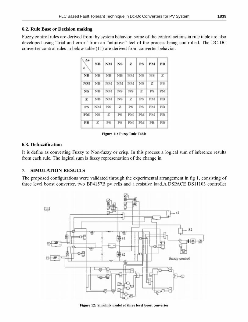
7. SIMULATION RESULTS
The proposed configurations were validated through the experimental arrangement in fig 1, consisting ofthree level boost converter, two BP4157B pv cells and a resistive load.A DSPACE DS11103 controller
Figure 12: Simulink model of three level boost converter

1840 P. Vijay Kumar and G. Nagarajan
board with a sampling time of 50 µs. Switches in the converter circuit are operating at a switching frequencyof 20 kHz.Fig (12) shows the proposed technologies implementation. For both open circuit and shortcircuit faults in power semiconductorswitches. In this paper I am concentrating on the voltage only.
When oc fault occur in converter the voltage level gets decrease in it. When sc fault occur in converterthe voltage gets zero. The appropriate wave forms are shown below
During the normal state, both the output voltages of two modules are add together. When oc fault occurin a switch, the pv array output voltage increase and its output current and output power are decreased
Figure 12(a): Output voltage of pv panel
Figure 12(b): Output voltage during normal state
Figure 12(c): Converter 1 during open circuit fault

FLC Based Fault Tolerant Technique in Dc-Dc Converters for PV System 1841
Figure 12(d):Converter2 during open circuit fault
Figure 12(e): Converter1 during short circuit fault
Figure 12(f): Converter2 during short circuit fault
suddenly. When sc fault occur in switch output voltage is zero. Two level boost converters with mpptcontrol for one module while another one will supply energy without mppt controller
The output power of the reconfigured converter produces less power compare to the original converter.The main drawback of this technique is it introduces higher stresses on healthy switches
8. CONCLUSION
A fault diagnostic method along with fault tolerant configuration based on fuzzy logic control for a threelevel boost converter in a power system applicable for charging batteries have been proposed. The Faultdiagnostic method uses only ordinary state control variables and its implementation is not sufficient.FuzzyConfiguration help to rearrange the healthy part of three level boost converters into two level converter.Thisconverter remains operating with MPPT control by providing only one of the pv module. Even thoughFault Tolerant operation of this converter provides less output power. The converter continue its operationby rearrange itself and it proves to be an efficient and cost effective option for all those applications wherethere is continues power supply is crucial issue.

1842 P. Vijay Kumar and G. Nagarajan
References
[1] E. Ribeiro “Fault Tolerant strategy for a DC-DC power converter” in IEEE Trans on power electrons Vol. 28, No. 6, June2013.
[2] N. G. Dhere, “Reliability of PV modules and balance-of-system components, “in Proc. Conf. Rec. 13st IEEE PhotovoltaicSpec., Jan. 2005, pp. 1570–1576.
[3] F. Nejabatkhah, S. Danyali, S. H. Hosseini, M. Sabahi, and S. M. Niapour, “Modeling and control of a new three-input dc–dc boost converter for hybrid PV/FC/battery power system,” IEEE Trans. Power Electron., vol. 27, no. 5, pp. 2309–2342,May 2012.
[4] G. Petrone, G. Spagnuolo, R. Teodorescu, M. Veer chary, and M. vitally, “Reliability issues in photovoltaic power processingsystems,” IEEETrans. Ind. Electron. vol. 55, no. 7, pp. 2569–2580, Jul. 2008.
[5] Eshan, Philippe Poure,Eskandar Gholipour and Shahrokh Saadate “single switch DC-DC converter with fault tolerantcapability under open-nd short switch failures” in IEEE TRNSACTIONS ON POWER ELECTRONICS, Vol, 30, No. 5,MY 2015.
[6] S. V. Dhople, A. Davoudi, A. D. Dominguez-Garcia, and P. L. Chapman, “A unified approach to reliability assessment ofmultiphase dc–dc convertersin photovoltaic energy conversion systems,” IEEE Trans. Power Electron., vol. 27, no. 2, pp.739–751, Feb. 2012.
[7] K. Ishaque, Z. Salam, M. Amjad, and S. Mekhilef, “An improved particleswarm optimization (PSO)-based MPPT for PVwith reduced steady-stateoscillation,” IEEE Trans. Power Electron., vol. 27, no. 8, pp. 3627–3638, Aug. 2012.
[8] Mahmud shahazar “OC AND SC switch fault diagnosis for Nonisolated DC-DC converters using Field ProgrammableGate Array” IEEE Trans power electron vol, 60, no. 9 Sept. 2013.
[9] P. Lezana, R. Aguilera, and J. Rodriguez, “Fault detection on multicellconverter based on output voltage frequency analysis,”IEEE Trans. Ind. Electron., vol. 56, no. 6, pp. 2275–2283, Jun. 2009.
[10] X. Pei, S. Nye, Y. Chen, and Y. Kang, “Open-circuit fault diagnosis andfault-tolerant strategies for full-bridge dc–dcconverters,” IEEE Trans.Power Electron., vol. 27, no. 5, pp. 2550–2565, May 2012.
[11] E. Ribera, A. Cardoso, and C. Boccaletti, “Open-circuit fault diagnosisin interleaved dc-dc converters,” IEEE Trans.Power Electron., vol. 29, no. 6, pp. 3091–3102, Jun. 2014.
[12] K. Ambuscade, V. Pickert, and B. Zahawi, “New circuit topology for faulttolerant H-bridge dc–dc converter,” IEEETrans. Power Electron., vol. 25, no. 6, pp. 1509–1516, Jun. 2010.
[13] S. Nie, X. Pei, Y. Chen, and Y. Kang, “Fault diagnosis of PWM dc-dcconverters based on magnetic component voltages,”IEEE Trans. Power Electron., vol. 29, no. 9, pp. 4978–4988, Sep. 2014.
[14] R. Jayabalan and B. Fahimi, “Monitoring and fault diagnosis of dc–dc multistage converter for hybrid electric vehicles,”in Proc. 5th IEEE Int.Symp. Diagn.Electra.Mach., Power Electron.Drives, Sep. 2005, pp. 1–6.
[15] X. Pei, S. Nye, Y. Chen, and Y. Kang, “Open-circuit fault diagnosis andfault-tolerant strategies for full-bridge dc–dcconverters,” IEEE Trans.Power Electron., vol. 27, no. 5, pp. 2550–2565, May 2012.
[16] W. Li and X. He, “Review of nonisolated high-step-up dc/dc converters in photovoltaic grid-connected applications,”IEEE Trans. Ind. Electron.,vol. 58, no. 4, pp. 1239–1250, Apr. 2011.
[17] ShanJamshedpur ‘’single switch DC-DC converter with Fault Tolerant capability under open and short circuit switchfailures’’ IEEE Trans,power electron, vol 30, no 5, May 2015.
[18] J. Kwon, B. Kwon, and K. Nam, “Three-phase photovoltaic system with three-level boostingMPPT control,” IEEE Trans.Power Electron., vol. 23, no. 5, pp. 2319–2327, Sep. 2008.
[19] W. Li and X. He, “Review of nonisolated high-step-up dc/dc convertersin photovoltaic grid-connected applications,”IEEE Trans. Ind. Electron.,vol. 58, no. 4, pp. 1239–1250, Apr. 2011.
[20] C. Hua, J. Lin, and C. Shen, “Implementation of a DSP-controlled photovoltaic system with peak power tracking,” IEEETrans. Ind. Electron., vol. 45, no. 1, pp. 99–107, Feb. 1998.
[21] J. Kwon, B. Kwon, and K. Nam, “Three-phase photovoltaic system withthree-level boostingMPPT control,” IEEE Trans.Power Electron., vol. 23, no. 5, pp. 2319–2327, Sep. 2008.
[22] M. G. Villella, J. R. Gasoil, and E. R. Filho, “Comprehensive approachto modeling and simulation of photovoltaic arrays,”IEEE Trans. PowerElectron., vol. 24, no. 5, pp. 1198–1208, May 2009.
[23] M. A. S. Masoum, H. Debone, and E. F. Fuchs, “Theoretical and experimental analyses of photovoltaic systems withvoltage and current-based maximum power-point tracking,” IEEE Trans. Energy Converts., vol. 17, no. 4, pp. 514–522,Dec. 2002.