fisher i2p-100 electro‐pneumatic transducer - …€¦ · fisher™ i2p-100 electro‐pneumatic...
TRANSCRIPT

www.Fisher.com
Fisher™ i2P-100 Electro‐Pneumatic Transducer
ContentsIntroduction 1. . . . . . . . . . . . . . . . . . . . . . . . . . . . . . . . .
Scope of Manual 1. . . . . . . . . . . . . . . . . . . . . . . . . . . . .Description 2. . . . . . . . . . . . . . . . . . . . . . . . . . . . . . . . .Specifications 2. . . . . . . . . . . . . . . . . . . . . . . . . . . . . . .Educational Services 2. . . . . . . . . . . . . . . . . . . . . . . . .
Installation 5. . . . . . . . . . . . . . . . . . . . . . . . . . . . . . . . . .Hazardous Area Classifications and Special
Instructions for “Safe Use” and Installationin Hazardous Locations 7. . . . . . . . . . . . . . . . . . . . .
Mounting 7. . . . . . . . . . . . . . . . . . . . . . . . . . . . . . . . . .Pneumatic Connections 8. . . . . . . . . . . . . . . . . . . . . .
Supply Pressure Requirements 9. . . . . . . . . . . . .Diagnostic Connections 10. . . . . . . . . . . . . . . . . .Vent 10. . . . . . . . . . . . . . . . . . . . . . . . . . . . . . . . . .
Electrical Connections 11. . . . . . . . . . . . . . . . . . . . . . .Operating Information 12. . . . . . . . . . . . . . . . . . . . . . . .
Calibration 12. . . . . . . . . . . . . . . . . . . . . . . . . . . . . . . .Equipment Required 12. . . . . . . . . . . . . . . . . . . . .Calibration Procedure 12. . . . . . . . . . . . . . . . . . . .
Principle of Operation 14. . . . . . . . . . . . . . . . . . . . . . . .Maintenance 14. . . . . . . . . . . . . . . . . . . . . . . . . . . . . . . .
Troubleshooting 16. . . . . . . . . . . . . . . . . . . . . . . . . . . .Converter Module Replacement 16. . . . . . . . . . . . . .Electronics Module Replacement 17. . . . . . . . . . . . . .Relay Maintenance 18. . . . . . . . . . . . . . . . . . . . . . . . . .
Figure 1. Fisher i2P‐100 Electro‐PneumaticTransducer
W8710
REPLACEABLEFILTER WITHREMOVABLEORIFICE
INTEGRAL PNEUMATICRELAY
VENT
Parts Ordering 19. . . . . . . . . . . . . . . . . . . . . . . . . . . . . . .Parts List 20. . . . . . . . . . . . . . . . . . . . . . . . . . . . . . . . . . .
Introduction
Scope of ManualThis instruction manual provides installation, operation, maintenance, and parts ordering information for the Fisheri2P‐100 transducer (see figure 1).
Refer to separate manuals for instructions covering equipment used with the transducer.
Do not install, operate, or maintain an i2P-100 electro‐pneumatic transducer without being fully trained and qualifiedin valve, actuator, and accessory installation, operation and maintenance. To avoid personal injury or propertydamage it is important to carefully read, understand, and follow all of the contents of this manual, including all safetycautions and warnings. If you have any questions about these instructions, contact your Emerson sales office or LocalBusiness Partner.
Instruction ManualD103198X012
i2P-100 TransducerJuly 2018

Instruction ManualD103198X012
i2P-100 TransducerJuly 2018
2
CAUTION
Dropping or rough handling of the transducer can cause damage to the converter module resulting in a shifted output or aminimum output.
DescriptionThe transducer receives a 4‐20 mA DC input signal and transmits a proportional user field‐configurable pneumaticoutput pressure to a final control element. The pneumatic output ranges are typically 0.2 to 1.0 bar (3 to 15 psig), 0.4 to 2.0 bar (6 to 30 psig), and 0.14 to 2.3 bar (2 to 33 psi). A typical application is in electronic control loops wherethe final control element is a control valve assembly that is pneumatically operated. The input signal and outputpressure range of the transducer is indicated on the nameplate, attached to the housing.
SpecificationsSpecifications for the i2P‐100 transducer are listed in table 1.
WARNING
This product is intended for a specific current range, temperature range and other application specifications. Applyingdifferent current, temperature and other service conditions could result in malfunction of the product, property damage orpersonal injury.
Educational ServicesFor information on available courses for the i2P‐100 electro‐pneumatic transducer, as well as a variety of otherproducts, contact:
Emerson Automation SolutionsEducational Services - RegistrationPhone: 1-641-754-3771 or 1-800-338-8158E-mail: [email protected]/fishervalvetraining
Go to:www.fisher.com/energyresponsibletool/to calculate pneumatic energy savings
Scan or clickcode to find outmore about thei2P-100 transducer
Instruction ManualD103198X012
i2P-100 TransducerJuly 2018
3
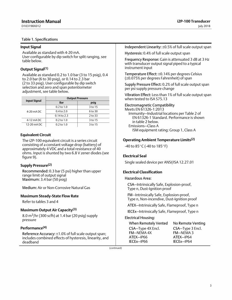
Table 1. Specifications
Input Signal
Available as standard with 4‐20 mA.User configurable by dip switch for split ranging, seetable below.
Output Signal(1)
Available as standard 0.2 to 1.0 bar (3 to 15 psig), 0.4to 2.0 bar (6 to 30 psig), or 0.14 to 2.3 bar (2 to 33 psig). User configurable by dip switchselection and zero and span potentiometeradjustment, see table below.
Input SignalOutput Pressure
Bar psig
4‐20 mA DC
0.2 to 1.0 3 to 15
0.4 to 2.0 6 to 30
0.14 to 2.3 2 to 33
4‐12 mA DC 0.2 to 1.0 3 to 15
12‐20 mA DC 0.2 to 1.0 3 to 15
Equivalent Circuit
The i2P‐100 equivalent circuit is a series circuitconsisting of a constant voltage drop (battery) ofapproximately 4 VDC and a total resistance of 40ohms. Input is shunted by two 6.8 V zener diodes (seefigure 9).
Supply Pressure(2)
Recommended: 0.3 bar (5 psi) higher than upperrange limit of output signalMaximum: 3.4 bar (50 psig)
Medium: Air or Non-Corrosive Natural Gas
Maximum Steady-State Flow Rate
Refer to tables 3 and 4
Maximum Output Air Capacity(3)
8.0 m3/hr (300 scfh) at 1.4 bar (20 psig) supplypressure
Performance(4)
Reference Accuracy: ±1.0% of full scale output span;includes combined effects of hysteresis, linearity, anddeadband
Independent Linearity: ±0.5% of full scale output span
Hysteresis: 0.4% of full scale output span
Frequency Response: Gain is attenuated 3 dB at 3 Hzwith transducer output signal piped to a typicalinstrument input
Temperature Effect: ±0.14% per degrees Celsius(±0.075% per degrees Fahrenheit) of span
Supply Pressure Effect: 0.2% of full scale output spanper psi supply pressure change
Vibration Effect: Less than 1% of full scale output spanwhen tested to ISA S75.13
Electromagnetic CompatibilityMeets EN 61326‐1:2013�Immunity—Industrial locations per Table 2 of��EN 61326‐1 Standard. Performance is shown��in table 2 below.�Emissions—Class A��ISM equipment rating: Group 1, Class A
Operating Ambient Temperature Limits(2)
-40 to 85�C (-40 to 185�F)
Electrical Seal
Single sealed device per ANSI/ISA 12.27.01
Electrical Classification
Hazardous Area:
CSA—Intrinsically Safe, Explosion-proof,Type n, Dust‐Ignition proof
FM—Intrinsically Safe, Explosion-proof, Type n, Non‐incendive, Dust‐Ignition proof
ATEX—Intrinsically Safe, Flameproof, Type n
IECEx—Intrinsically Safe, Flameproof, Type n
Electrical Housing:
When Remotely Vented No Remote Venting
CSA—Type 4X Encl.FM—NEMA 4XATEX—IP66IECEx—IP66
CSA—Type 3 Encl.FM—NEMA 3ATEX—IP64IECEx—IP64
(continued)
Instruction ManualD103198X012
i2P-100 TransducerJuly 2018
4
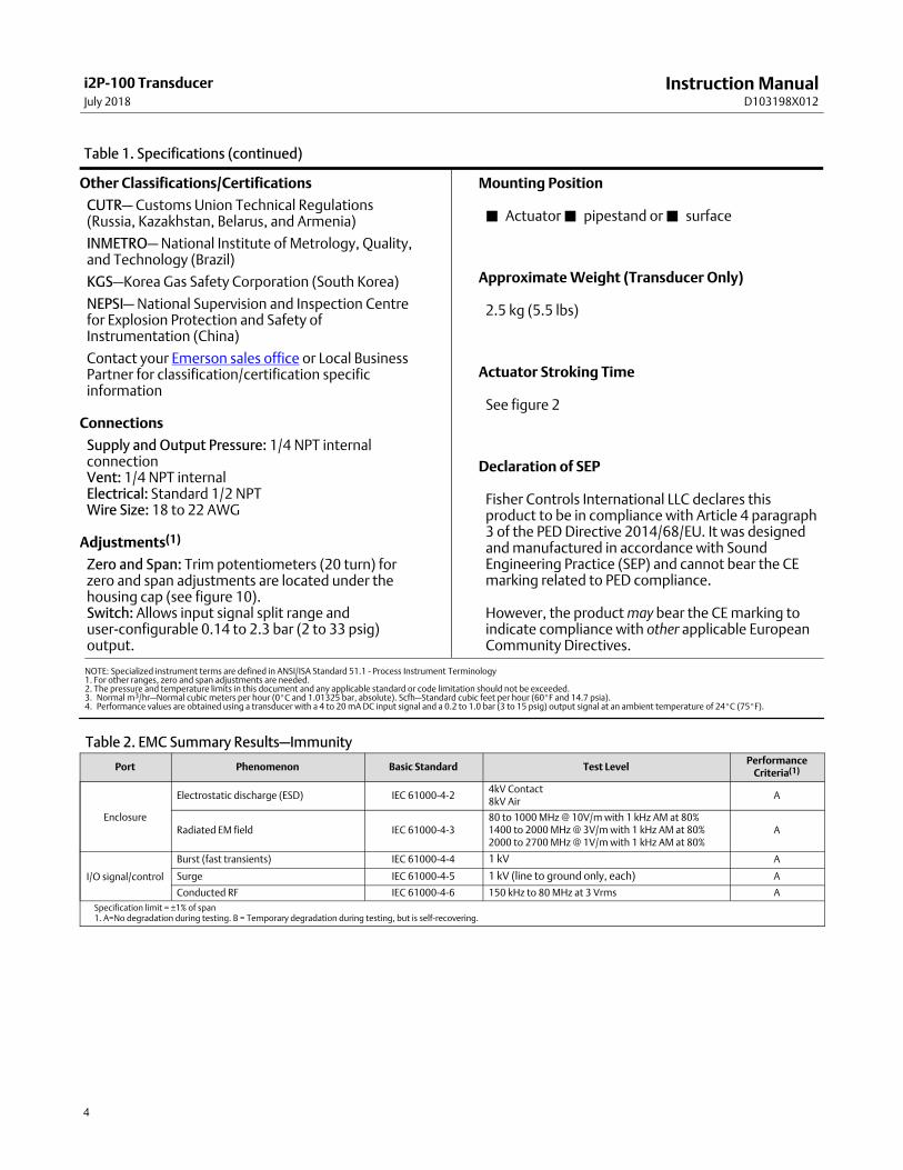
Table 1. Specifications (continued)
Other Classifications/Certifications
CUTR— Customs Union Technical Regulations (Russia, Kazakhstan, Belarus, and Armenia)
INMETRO— National Institute of Metrology, Quality,and Technology (Brazil)
KGS—Korea Gas Safety Corporation (South Korea)
NEPSI— National Supervision and Inspection Centrefor Explosion Protection and Safety ofInstrumentation (China)
Contact your Emerson sales office or Local BusinessPartner for classification/certification specificinformation
Connections
Supply and Output Pressure: 1/4 NPT internalconnectionVent: 1/4 NPT internalElectrical: Standard 1/2 NPTWire Size: 18 to 22 AWG
Adjustments(1)
Zero and Span: Trim potentiometers (20 turn) forzero and span adjustments are located under thehousing cap (see figure 10).Switch: Allows input signal split range anduser‐configurable 0.14 to 2.3 bar (2 to 33 psig)output.
Mounting Position
� Actuator � pipestand or � surface
Approximate Weight (Transducer Only)
2.5 kg (5.5 lbs)
Actuator Stroking Time
See figure 2
Declaration of SEP
Fisher Controls International LLC declares thisproduct to be in compliance with Article 4 paragraph3 of the PED Directive 2014/68/EU. It was designedand manufactured in accordance with SoundEngineering Practice (SEP) and cannot bear the CEmarking related to PED compliance.
However, the product may bear the CE marking toindicate compliance with other applicable EuropeanCommunity Directives.
NOTE: Specialized instrument terms are defined in ANSI/ISA Standard 51.1 - Process Instrument Terminology1. For other ranges, zero and span adjustments are needed.2. The pressure and temperature limits in this document and any applicable standard or code limitation should not be exceeded.3. Normal m3/hr—Normal cubic meters per hour (0�C and 1.01325 bar, absolute). Scfh—Standard cubic feet per hour (60�F and 14.7 psia).4. Performance values are obtained using a transducer with a 4 to 20 mA DC input signal and a 0.2 to 1.0 bar (3 to 15 psig) output signal at an ambient temperature of 24�C (75�F).
Table 2. EMC Summary Results—Immunity
Port Phenomenon Basic Standard Test LevelPerformance
Criteria(1)
Enclosure
Electrostatic discharge (ESD) IEC 61000‐4‐24kV Contact8kV Air
A
Radiated EM field IEC 61000‐4‐380 to 1000 MHz @ 10V/m with 1 kHz AM at 80%1400 to 2000 MHz @ 3V/m with 1 kHz AM at 80%2000 to 2700 MHz @ 1V/m with 1 kHz AM at 80%
A
I/O signal/control
Burst (fast transients) IEC 61000‐4‐4 1 kV A
Surge IEC 61000‐4‐5 1 kV (line to ground only, each) A
Conducted RF IEC 61000‐4‐6 150 kHz to 80 MHz at 3 Vrms A
Specification limit = ±1% of span1. A=No degradation during testing. B = Temporary degradation during testing, but is self‐recovering.
Instruction ManualD103198X012
i2P-100 TransducerJuly 2018
5
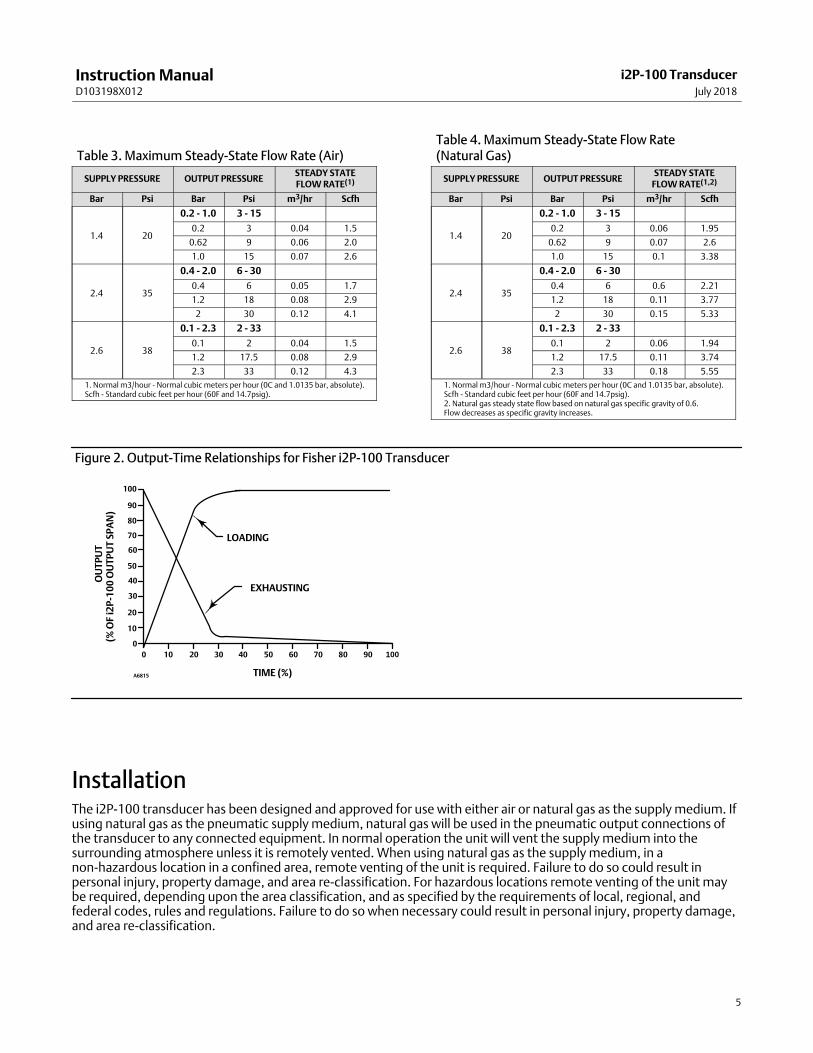
Table 3. Maximum Steady-State Flow Rate (Air)
SUPPLY PRESSURE OUTPUT PRESSURESTEADY STATEFLOW RATE(1)
Bar Psi Bar Psi m3/hr Scfh
1.4 20
0.2 - 1.0 3 - 15
0.2 3 0.04 1.5
0.62 9 0.06 2.0
1.0 15 0.07 2.6
2.4 35
0.4 - 2.0 6 - 30
0.4 6 0.05 1.7
1.2 18 0.08 2.9
2 30 0.12 4.1
2.6 38
0.1 - 2.3 2 - 33
0.1 2 0.04 1.5
1.2 17.5 0.08 2.9
2.3 33 0.12 4.3
1. Normal m3/hour - Normal cubic meters per hour (0C and 1.0135 bar, absolute).Scfh - Standard cubic feet per hour (60F and 14.7psig).
Table 4. Maximum Steady-State Flow Rate (Natural Gas)
SUPPLY PRESSURE OUTPUT PRESSURESTEADY STATE
FLOW RATE(1,2)
Bar Psi Bar Psi m3/hr Scfh
1.4 20
0.2 - 1.0 3 - 15
0.2 3 0.06 1.95
0.62 9 0.07 2.6
1.0 15 0.1 3.38
2.4 35
0.4 - 2.0 6 - 30
0.4 6 0.6 2.21
1.2 18 0.11 3.77
2 30 0.15 5.33
2.6 38
0.1 - 2.3 2 - 33
0.1 2 0.06 1.94
1.2 17.5 0.11 3.74
2.3 33 0.18 5.55
1. Normal m3/hour - Normal cubic meters per hour (0C and 1.0135 bar, absolute).Scfh - Standard cubic feet per hour (60F and 14.7psig).2. Natural gas steady state flow based on natural gas specific gravity of 0.6.Flow decreases as specific gravity increases.
Figure 2. Output‐Time Relationships for Fisher i2P‐100 Transducer
LOADING
EXHAUSTING
TIME (%)
0 10 20 30 40 50 60 70 80 90 1000
10
20
30
40
50
60
70
80
90
100
OU
TP
UT
A6815
(% O
F i2
P‐1
00
OU
TP
UT
SP
AN
)
InstallationThe i2P‐100 transducer has been designed and approved for use with either air or natural gas as the supply medium. Ifusing natural gas as the pneumatic supply medium, natural gas will be used in the pneumatic output connections ofthe transducer to any connected equipment. In normal operation the unit will vent the supply medium into thesurrounding atmosphere unless it is remotely vented. When using natural gas as the supply medium, in anon‐hazardous location in a confined area, remote venting of the unit is required. Failure to do so could result inpersonal injury, property damage, and area re‐classification. For hazardous locations remote venting of the unit maybe required, depending upon the area classification, and as specified by the requirements of local, regional, andfederal codes, rules and regulations. Failure to do so when necessary could result in personal injury, property damage,and area re‐classification.
Instruction ManualD103198X012
i2P-100 TransducerJuly 2018
6
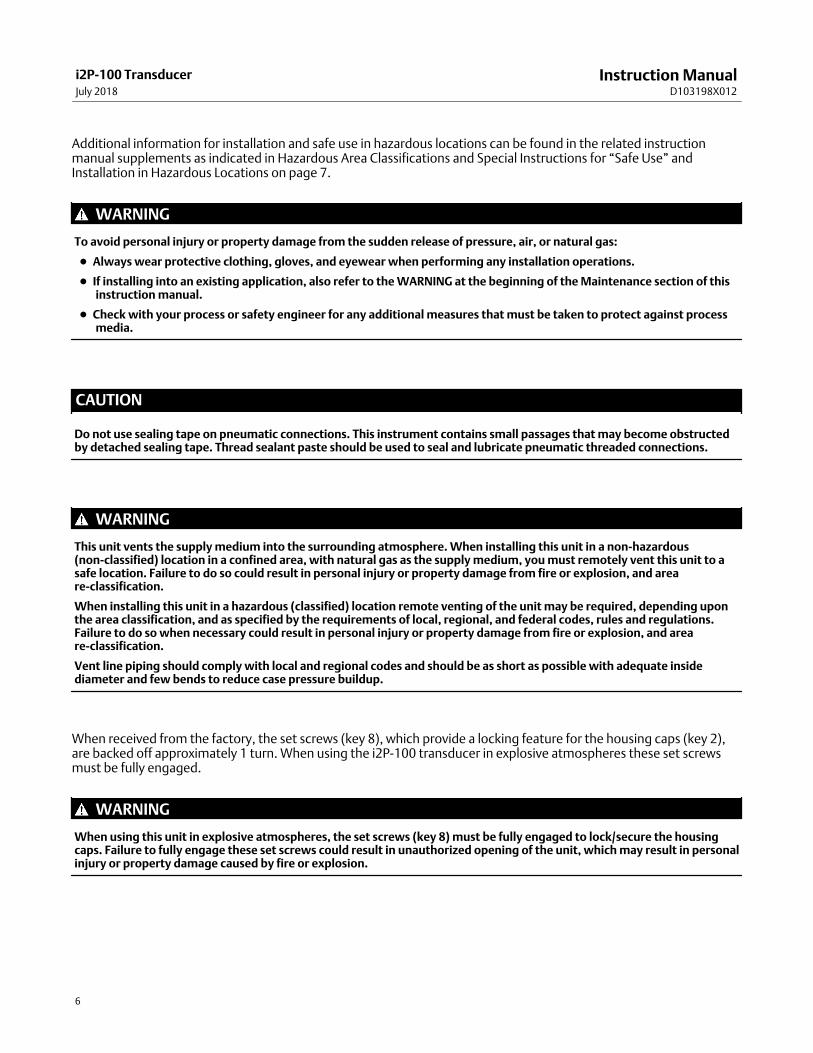
Additional information for installation and safe use in hazardous locations can be found in the related instructionmanual supplements as indicated in Hazardous Area Classifications and Special Instructions for “Safe Use” andInstallation in Hazardous Locations on page 7.
WARNING
To avoid personal injury or property damage from the sudden release of pressure, air, or natural gas:
� Always wear protective clothing, gloves, and eyewear when performing any installation operations.
� If installing into an existing application, also refer to the WARNING at the beginning of the Maintenance section of thisinstruction manual.
� Check with your process or safety engineer for any additional measures that must be taken to protect against processmedia.
CAUTION
Do not use sealing tape on pneumatic connections. This instrument contains small passages that may become obstructedby detached sealing tape. Thread sealant paste should be used to seal and lubricate pneumatic threaded connections.
WARNING
This unit vents the supply medium into the surrounding atmosphere. When installing this unit in a non‐hazardous(non‐classified) location in a confined area, with natural gas as the supply medium, you must remotely vent this unit to asafe location. Failure to do so could result in personal injury or property damage from fire or explosion, and areare‐classification.
When installing this unit in a hazardous (classified) location remote venting of the unit may be required, depending uponthe area classification, and as specified by the requirements of local, regional, and federal codes, rules and regulations.Failure to do so when necessary could result in personal injury or property damage from fire or explosion, and areare‐classification.
Vent line piping should comply with local and regional codes and should be as short as possible with adequate insidediameter and few bends to reduce case pressure buildup.
When received from the factory, the set screws (key 8), which provide a locking feature for the housing caps (key 2),are backed off approximately 1 turn. When using the i2P‐100 transducer in explosive atmospheres these set screwsmust be fully engaged.
WARNING
When using this unit in explosive atmospheres, the set screws (key 8) must be fully engaged to lock/secure the housingcaps. Failure to fully engage these set screws could result in unauthorized opening of the unit, which may result in personalinjury or property damage caused by fire or explosion.

Instruction ManualD103198X012
i2P-100 TransducerJuly 2018
7
Hazardous Area Classifications and Special Instructions for “Safe Use” andInstallation in Hazardous LocationsRefer to the following instruction manual supplements for approval information.
� CSA Approval Information for Fisher i2P-100 Electro-Pneumatic Transducer (D104192X012)
� FM Approval Information for Fisher i2P-100 Electro-Pneumatic Transducer (D104193X012)
� ATEX Approval Information for Fisher i2P-100 Electro-Pneumatic Transducer (D104194X012)
� IECEx Approval Information for Fisher i2P-100 Electro-Pneumatic Transducer (D104195X012)
All documents are available from your Emerson sales office or Local Business Partner, or at www.Fisher.com. Contactyour Emerson sales office for all other approval/certification information.
MountingWhen a transducer is ordered as part of a control valve assembly, the factory mounts the transducer on the actuatorand connects the necessary tubing, then adjusts the transducer as specified on the order. See figures 3 and 4 fortypical mounting configurations.
Figure 3. Fisher i2P‐100 Electro‐PneumaticTransducer Mounted on a Size 30 667 Sliding‐StemActuator
W8723
CONDUITCONNECTION
FIELDTERMINATION ANDELECTRONICSMODULE CAP
CONVERTERMODULE CAP
Figure 4. Fisher i2P‐100 Electro‐PneumaticTransducer Mounted on a 2052 Rotary Actuator with 3610J Positioner and V300B Rotary Valve
X1354
CONDUITCONNECTION
FIELD TERMINATIONAND ELECTRONICSMODULE CAP
CONVERTERMODULE CAP
Transducers also can be ordered separately for mounting on a control valve assembly already in service, or formounting on a 2 inch diameter pipestand, or a flat surface. The transducer may be ordered either with or withoutmounting parts.

Instruction ManualD103198X012
i2P-100 TransducerJuly 2018
8
CAUTION
Do not mount the vent in a downward position as the vent will not drain properly and may become blocked with ice ordebris, resulting in process instability.
Mounting parts include a mounting plate and bolts and, if ordered for pipestand mounting, a pipe clamp. Tubing is notincluded if the transducer is not factory mounted. Use 3/8‐inch diameter tubing for all input and output connections.The length of tubing between the transducer output and the final control element should be as short as possible.Transducer overall dimensions are shown in figure 5. If weatherproofing is required, mount the transducer so that thevent can drain. Do not allow moisture or condensate to collect in the vent.
Pneumatic Connections
CAUTION
Do not use sealing tape on pneumatic connections. This instrument contains small passages that may become obstructedby detached sealing tape. Thread sealant paste should be used to seal and lubricate pneumatic threaded connections.
As shown in figure 5, all pressure connections on the transducer are 1/4 NPT internal connections. Use 3/8‐inch tubingfor all pressure connections. Refer to the vent subsection below for remote vent connections.
Figure 5. Dimensions and Connections
58.7(2.31)
22.3(0.88)
75.2(2.96)
55.7(2.19)
33.3(1.31)
67.8(2.67)
75.7(2.98)
22.9(0.90)
33.3(1.31)
33.3(1.31)
67 (2.62) CAPREMOVALCLEARANCE
67 (2.62) CAPREMOVALCLEARANCE
1/4 18 NPTSUPPLYCONNECTION
1/2 14 NPTCONDUITCONNECTION
81
.6(3
.21
)7
4.2
(2.9
2)
34
.7(1
.37
)9
8.7
(3.8
9)
mm(INCH)
GE0643(sheet 1 of 4)
1/4 18 NPTOUTPUTCONNECTION
10
3.9
(4.0
9)
10
3.9
(4.0
9)3
6.3
(1.4
3)
1/4 18 NPTOUTPUT
CONNECTION
1/4 18 NPT VENTOR PIPE‐A‐WAYCONNECTION
Instruction ManualD103198X012
i2P-100 TransducerJuly 2018
9
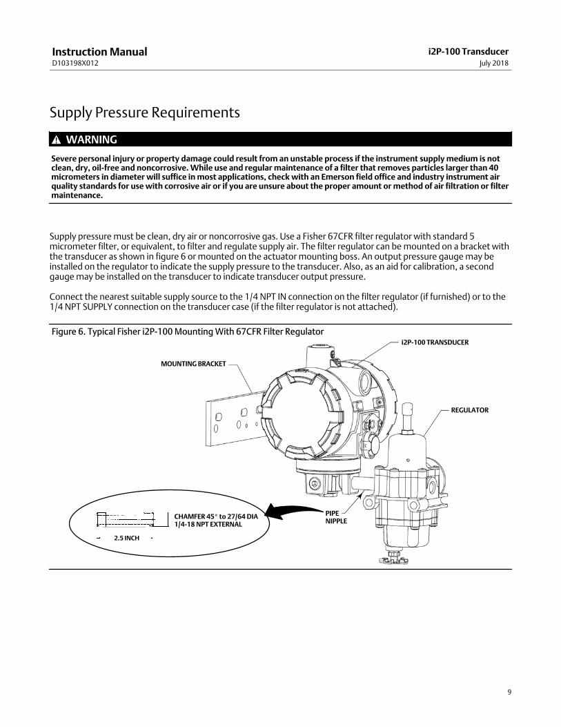
Supply Pressure Requirements
WARNING
Severe personal injury or property damage could result from an unstable process if the instrument supply medium is notclean, dry, oil‐free and noncorrosive. While use and regular maintenance of a filter that removes particles larger than 40micrometers in diameter will suffice in most applications, check with an Emerson field office and industry instrument airquality standards for use with corrosive air or if you are unsure about the proper amount or method of air filtration or filtermaintenance.
Supply pressure must be clean, dry air or noncorrosive gas. Use a Fisher 67CFR filter regulator with standard 5micrometer filter, or equivalent, to filter and regulate supply air. The filter regulator can be mounted on a bracket withthe transducer as shown in figure 6 or mounted on the actuator mounting boss. An output pressure gauge may beinstalled on the regulator to indicate the supply pressure to the transducer. Also, as an aid for calibration, a secondgauge may be installed on the transducer to indicate transducer output pressure.
Connect the nearest suitable supply source to the 1/4 NPT IN connection on the filter regulator (if furnished) or to the1/4 NPT SUPPLY connection on the transducer case (if the filter regulator is not attached).
MOUNTING BRACKET
i2P‐100 TRANSDUCER
REGULATOR
PIPENIPPLE
2.5 INCH
CHAMFER 45� to 27/64 DIA1/4‐18 NPT EXTERNAL
Figure 6. Typical Fisher i2P‐100 Mounting With 67CFR Filter Regulator
Instruction ManualD103198X012
i2P-100 TransducerJuly 2018
10
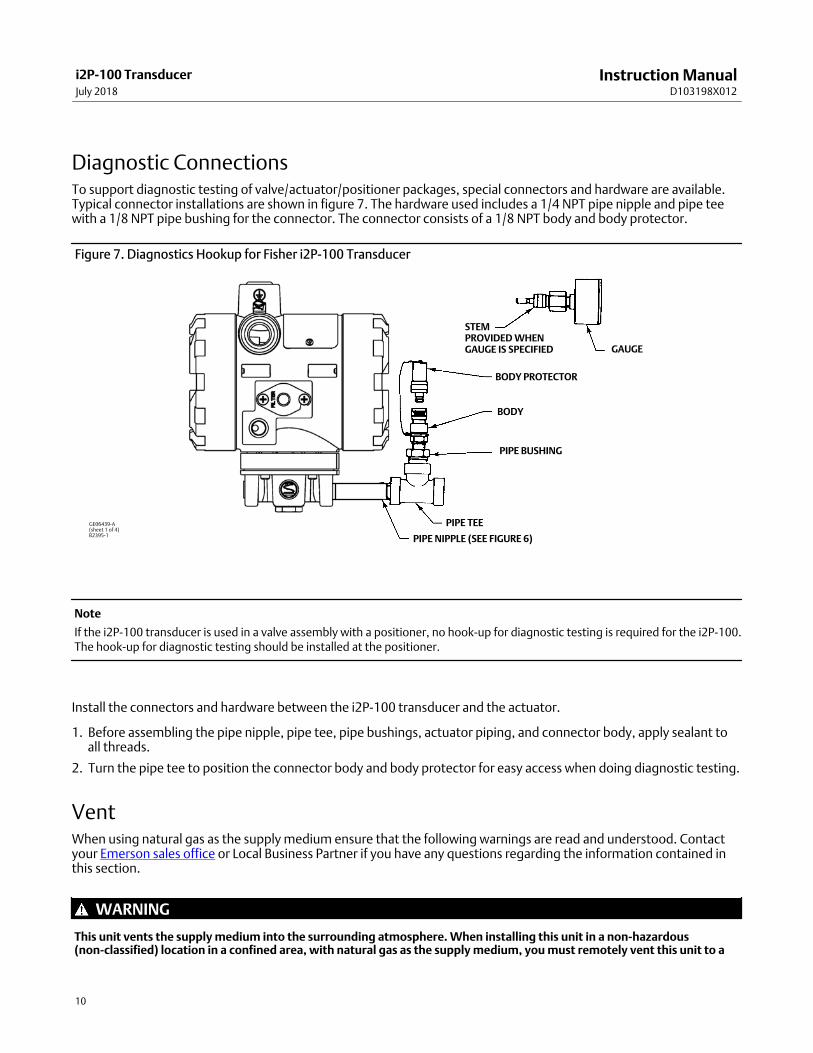
Diagnostic ConnectionsTo support diagnostic testing of valve/actuator/positioner packages, special connectors and hardware are available.Typical connector installations are shown in figure 7. The hardware used includes a 1/4 NPT pipe nipple and pipe teewith a 1/8 NPT pipe bushing for the connector. The connector consists of a 1/8 NPT body and body protector.
Figure 7. Diagnostics Hookup for Fisher i2P‐100 Transducer
PIPE BUSHING
BODY PROTECTOR
BODY
PIPE TEE
PIPE NIPPLE (SEE FIGURE 6)
STEMPROVIDED WHENGAUGE IS SPECIFIED GAUGE
GE06439‐A (sheet 1 of 4)B2395‐1
Note
If the i2P‐100 transducer is used in a valve assembly with a positioner, no hook‐up for diagnostic testing is required for the i2P‐100.The hook‐up for diagnostic testing should be installed at the positioner.
Install the connectors and hardware between the i2P‐100 transducer and the actuator.
1. Before assembling the pipe nipple, pipe tee, pipe bushings, actuator piping, and connector body, apply sealant toall threads.
2. Turn the pipe tee to position the connector body and body protector for easy access when doing diagnostic testing.
VentWhen using natural gas as the supply medium ensure that the following warnings are read and understood. Contactyour Emerson sales office or Local Business Partner if you have any questions regarding the information contained inthis section.
WARNING
This unit vents the supply medium into the surrounding atmosphere. When installing this unit in a non‐hazardous(non‐classified) location in a confined area, with natural gas as the supply medium, you must remotely vent this unit to a

Instruction ManualD103198X012
i2P-100 TransducerJuly 2018
11
safe location. Failure to do so could result in personal injury or property damage from fire or explosion, and areare‐classification.
When installing this unit in a hazardous (classified) location remote venting of the unit may be required, depending uponthe area classification, and as specified by the requirements of local, regional, and federal codes, rules and regulations.Failure to do so when necessary could result in personal injury or property damage from fire or explosion, and areare‐classification.
Vent line piping should comply with local and regional codes and should be as short as possible with adequate insidediameter and few bends to reduce case pressure buildup.
If a remote vent is required, the vent line must be as short as possible with a minimum number of bends and elbows.To connect a remote vent, remove the plastic vent (key 71, figure 13). The vent connection is 1/4 NPT internal. Use3/8‐inch tubing to provide a remote vent.
Electrical Connections
WARNING
For explosion‐proof applications, or when using natural gas as the supply medium, disconnect power before removing thehousing cap. Personal injury or property damage from fire or explosion may result if power is not disconnected beforeremoving the cap.
For intrinsically safe installations, refer to the nameplate or to instructions provided by the barrier manufacturer for properwiring and installation.
Note
For North American explosion‐proof applications in the Class/Division system, the i2P‐100 has been designed such that a conduitseal is not required. For all other applications install the product as per local, regional, or national code, rules, and regulations.
WARNING
Select wiring and/or cable glands that are rated for the environment of use (such as hazardous location, ingress protection,and temperature). Failure to use properly rated wiring and/or cable glands can result in personal injury or property damagefrom fire or explosion.
Wiring connections must be in accordance with local, regional, and national codes for any given hazardous area approval.Failure to follow the local, regional, and national codes could result in personal injury or property damage from fire orexplosion.
Use the 1/2 NPT conduit connection, shown in figure 5, for installation of field wiring.
Refer to figures 8, 9, and 10 when connecting field wiring from the control device to the transducer. Connect thepositive wire from the control device to the transducer “+” terminal and, the negative wire from the control device tothe transducer “-” terminal. Do not overtighten the terminal screws. Maximum torque is 0.45 N�m (4 lbf�in.). Connectthe transducer grounding terminal to earth ground.
Grounding terminals are provided both inside and outside the transducer housing.
Instruction ManualD103198X012
i2P-100 TransducerJuly 2018
12
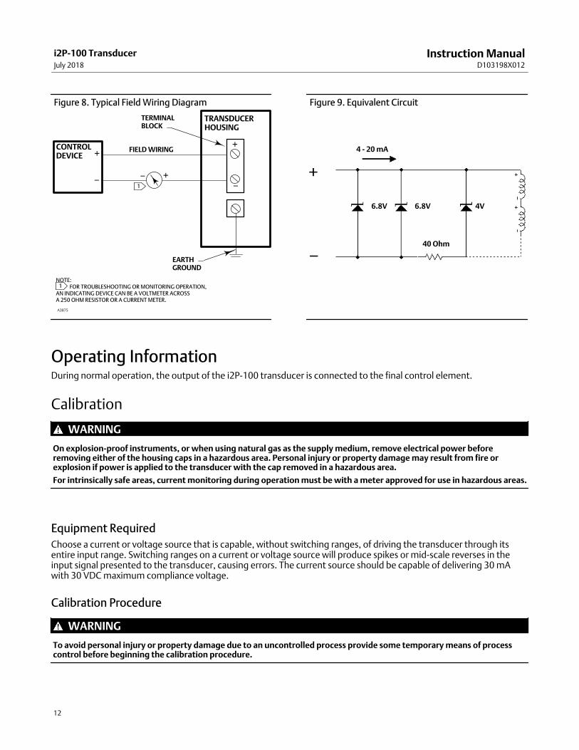
Figure 8. Typical Field Wiring Diagram
+
−
+
− − +1
CONTROLDEVICE
TRANSDUCERHOUSING
TERMINALBLOCK
FIELD WIRING
EARTHGROUND
NOTE: �� FOR TROUBLESHOOTING OR MONITORING OPERATION,AN INDICATING DEVICE CAN BE A VOLTMETER ACROSS A 250 OHM RESISTOR OR A CURRENT METER.
1
A3875
Figure 9. Equivalent Circuit
4 - 20 mA
6.8V 6.8V 4V
40 Ohm
Operating InformationDuring normal operation, the output of the i2P‐100 transducer is connected to the final control element.
Calibration
WARNING
On explosion‐proof instruments, or when using natural gas as the supply medium, remove electrical power beforeremoving either of the housing caps in a hazardous area. Personal injury or property damage may result from fire orexplosion if power is applied to the transducer with the cap removed in a hazardous area.
For intrinsically safe areas, current monitoring during operation must be with a meter approved for use in hazardous areas.
Equipment Required
Choose a current or voltage source that is capable, without switching ranges, of driving the transducer through itsentire input range. Switching ranges on a current or voltage source will produce spikes or mid‐scale reverses in theinput signal presented to the transducer, causing errors. The current source should be capable of delivering 30 mAwith 30 VDC maximum compliance voltage.
Calibration Procedure
WARNING
To avoid personal injury or property damage due to an uncontrolled process provide some temporary means of processcontrol before beginning the calibration procedure.
Instruction ManualD103198X012
i2P-100 TransducerJuly 2018
13
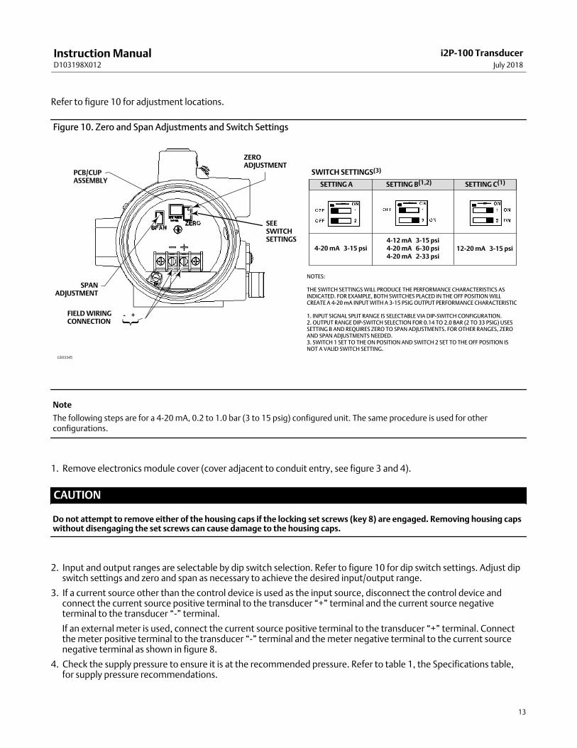
Refer to figure 10 for adjustment locations.
Figure 10. Zero and Span Adjustments and Switch Settings
NOTES:
THE SWITCH SETTINGS WILL PRODUCE THE PERFORMANCE CHARACTERISTICS ASINDICATED. FOR EXAMPLE, BOTH SWITCHES PLACED IN THE OFF POSITION WILLCREATE A 4‐20 mA INPUT WITH A 3‐15 PSIG OUTPUT PERFORMANCE CHARACTERISTIC
1. INPUT SIGNAL SPLIT RANGE IS SELECTABLE VIA DIP‐SWITCH CONFIGURATION.2. OUTPUT RANGE DIP‐SWITCH SELECTION FOR 0.14 TO 2.0 BAR (2 TO 33 PSIG) USESSETTING B AND REQUIRES ZERO TO SPAN ADJUSTMENTS. FOR OTHER RANGES, ZEROAND SPAN ADJUSTMENTS NEEDED.3. SWITCH 1 SET TO THE ON POSITION AND SWITCH 2 SET TO THE OFF POSITION ISNOT A VALID SWITCH SETTING.
GE03345
SETTING A SETTING B(1,2) SETTING C(1)
PCB/CUPASSEMBLY
SPANADJUSTMENT
FIELD WIRINGCONNECTION
SWITCH SETTINGS(3)
ZEROADJUSTMENT
4‐20 mA 3‐15 psi4‐12 mA 3‐15 psi4‐20 mA 6‐30 psi4‐20 mA 2‐33 psi
12‐20 mA 3‐15 psi
{- +
SEESWITCHSETTINGS
Note
The following steps are for a 4‐20 mA, 0.2 to 1.0 bar (3 to 15 psig) configured unit. The same procedure is used for otherconfigurations.
1. Remove electronics module cover (cover adjacent to conduit entry, see figure 3 and 4).
CAUTION
Do not attempt to remove either of the housing caps if the locking set screws (key 8) are engaged. Removing housing capswithout disengaging the set screws can cause damage to the housing caps.
2. Input and output ranges are selectable by dip switch selection. Refer to figure 10 for dip switch settings. Adjust dipswitch settings and zero and span as necessary to achieve the desired input/output range.
3. If a current source other than the control device is used as the input source, disconnect the control device andconnect the current source positive terminal to the transducer “+” terminal and the current source negativeterminal to the transducer “-” terminal.
If an external meter is used, connect the current source positive terminal to the transducer “+” terminal. Connectthe meter positive terminal to the transducer “-” terminal and the meter negative terminal to the current sourcenegative terminal as shown in figure 8.
4. Check the supply pressure to ensure it is at the recommended pressure. Refer to table 1, the Specifications table,for supply pressure recommendations.
Instruction ManualD103198X012
i2P-100 TransducerJuly 2018
14
5. Adjust the input current to the low mA DC.
6. The output pressure should be 0.2 bar (3 psig). If not, adjust the ZERO potentiometer until the output pressure is 0.2 bar (3 psig).
7. Adjust the input current to the high mA DC.
8. The output pressure should be 1.0 bar (15 psig). If not, adjust the SPAN potentiometer until the output pressureis 1.0 bar (15 psig).
9. Repeat steps 5 through 8 until the output pressure is within the referenced accuracy requirements without furtheradjustment.
10. If a current source other than the control device was used, disconnect the current source and reconnect the controldevice.
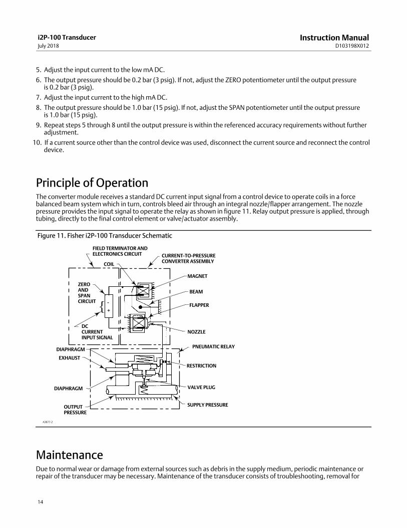
Principle of OperationThe converter module receives a standard DC current input signal from a control device to operate coils in a forcebalanced beam system which in turn, controls bleed air through an integral nozzle/flapper arrangement. The nozzlepressure provides the input signal to operate the relay as shown in figure 11. Relay output pressure is applied, throughtubing, directly to the final control element or valve/actuator assembly.
Figure 11. Fisher i2P‐100 Transducer Schematic
COIL
ZEROANDSPAN CIRCUIT
DC CURRENTINPUT SIGNAL
PNEUMATIC RELAYDIAPHRAGM
EXHAUST
DIAPHRAGM
OUTPUTPRESSURE
MAGNET
BEAM
FLAPPER
NOZZLE
RESTRICTION
VALVE PLUG
SUPPLY PRESSURE
A3877-2
-
+{
CURRENT‐TO‐PRESSURECONVERTER ASSEMBLY
FIELD TERMINATOR ANDELECTRONICS CIRCUIT
�
�
MaintenanceDue to normal wear or damage from external sources such as debris in the supply medium, periodic maintenance orrepair of the transducer may be necessary. Maintenance of the transducer consists of troubleshooting, removal for
Instruction ManualD103198X012
i2P-100 TransducerJuly 2018
15
inspection, and replacement of component parts, as well as removal and inspection of the external removablefilter/restriction and cleaning or replacing as necessary (see figure 1).
WARNING
To avoid personal injury or property damage from the sudden release of pressure, air or natural gas:
� Always wear protective clothing, gloves, and eyewear when performing any maintenance operations.
� Do not remove the actuator from the valve while the valve is still pressurized.
� Disconnect any operating lines providing air pressure, electric power, or a control signal to the actuator. Be sure theactuator cannot suddenly open or close the valve.
� Use bypass valves or completely shut off the process to isolate the valve from process pressure. Relieve process pressureon both sides of the valve.
� Use lock‐out procedures to be sure that the above measures stay in effect while you work on the equipment.
� Check with your process or safety engineer for any additional measures that must be taken to protect against processmedia.
WARNING
When using natural gas as the supply medium, or for explosion proof applications, the following warnings also apply:
� Remove electrical power before removing either housing cap. Personal injury or property damage from fire orexplosion may result if power is not disconnected before removing either cap.
� Remove electrical power before disconnecting any of the pneumatic connections or removing the external removablefilter/restriction.
When disconnecting any of the pneumatic connections or the external removable filter/restriction, natural gas will seepfrom the unit and any connected equipment into the surrounding atmosphere. Personal injury or property damage mayresult from fire or explosion if preventative measures are not taken, such as adequate ventilation and the removal of anyignition sources.
CAUTION
Do not attempt to remove either of the housing caps if the locking set screws (key 8) are engaged. Removing housing capswithout disengaging the set screws can cause damage to the housing caps.
CAUTION
When replacing components, use only components specified by the factory. Always use proper component replacementtechniques, as presented in this manual. Improper techniques or component selection may invalidate the approvals andthe product specifications, as indicated in table 1. It may also impair operations and the intended function of the device.
The converter module and the electronics module are non‐repairable. If troubleshooting or alignment attempts indicate afaulty converter or electronics module, replace the module or return the transducer to your Emerson sales office or LocalBusiness Partner for repair.
Instruction ManualD103198X012
i2P-100 TransducerJuly 2018
16
TroubleshootingThe following procedures require taking the control valve/actuator assembly out of service. Provide some temporarymeans of process control before taking the control valve out of service.
Electrical1. Ensure terminal lug connections from the control device to the transducer are of the correct polarity (refer to the
electrical connection procedures in the Installation section of this manual).
2. At the transducer, ensure that the mA DC signal is applied, and ensure that it is within the 4 to 20 mA range.
3. Check switches and ensure that they are properly set. Refer to figure 10.
4. If the problem has not been resolved, see Electronics Module Replacement in this manual.
Pneumatic
Provide a 4‐30 mA DC current source, supply pressure, and a gauge to monitor the output pressure when checkingtransducer operation. Refer to figure 13 for key number locations.
1. Ensure that supply pressure to the transducer meets your requirements [0.3 bar (5 psi) higher than upper rangelimit of output signal, with a maximum of 3.4 bar (50 psi)].
2. Ensure that the filter (key 11) and restrictor (key 10) are open and clean. Remove the two screws (key 14), the filtercap (key 13) and the O‐ring (key 12) to access the filter and restrictor.
3. If a filter/regulator is used, ensure that it is working correctly. If not, ensure the dripwell is not plugged because ofexcessive moisture accumulation. If necessary, drain off any moisture, and clean or replace the filter element.
4. Force the converter module to maximum output pressure with a 30 mA DC signal. Output pressure should build upto the approximate value of the supply pressure [maximum of 3.4 bar (50 psi)].
5. When the input current is removed, the transducer output pressure should drop to less than 0.14 bar (2 psig). If itdoes not, check to ensure the vent and exhaust air passageway is free from foreign material.
6. To inspect the relay assembly, refer to the Relay Maintenance procedures in this manual.
7. If the problem has not been resolved, see Converter Module Replacement in this manual.
Converter Module Replacement
Removal
Refer to figure 13 for key number locations.
1. Disconnect operating lines providing air pressure, electric power, or a control signal to the actuator. If using gas asthe supply medium remove electrical power before removing the housing cap.
2. Remove the housing cap (key 2) (the cap farthest away from the conduit). Note that the set screw associated withthis housing cap (key 8) needs to be loosened to remove the cap.
3. Unscrew the two captive screws (key 52) and remove the converter module from the housing.
4. Inspect the O‐ring (key 55) and replace if necessary.

Instruction ManualD103198X012
i2P-100 TransducerJuly 2018
17
Replacement1. Lubricate the O‐ring (key 55) with a silicone sealant before replacing the converter module in the housing.
2. Insert the converter module into position in the housing (key 1). Replace the two screws (key 52) and tighten them.
3. Replace the housing cap (key 2), making sure to re‐tighten the set screw (key 8).
4. Electrically calibrate the unit using the procedure in the Calibration section of this manual.
Electronics Module Replacement
Removal
Refer to figure 13 for key number locations.
1. Disconnect operating lines providing air pressure, electric power, or a control signal to the actuator. If using gas asthe supply medium remove electrical power before removing the housing cap.
2. Remove the housing cap (key 2) (the cap closest to the conduit). Note that the set screw (key 8) associated with thishousing cap needs to be loosened to remove the cap.
3. Note the location of the wires, then remove the electrical wiring from the terminal block.
4. Remove the three screws (key 26) and remove the electronics module from the housing.
Replacement1. Insert the electronics module into position in the housing (key 1). Replace the three screws (key 26) and tighten
them.
2. Replace the electrical wiring removed in step 1 of the removal procedures. Do not overtighten the terminal screws.Maximum torque is 0.45 N�m (4 lbf�in).
3. Electrically calibrate the unit using the procedure in the Calibration section of this manual.
4. Replace the housing cap (key 2), making sure to re‐tighten the set screw (key 8).
Instruction ManualD103198X012
i2P-100 TransducerJuly 2018
18
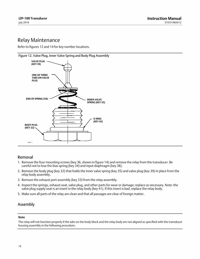
Relay MaintenanceRefer to figures 12 and 14 for key number locations.
Figure 12. Valve Plug, Inner Valve Spring and Body Plug Assembly
VALVE PLUG(KEY 39)
ONE OF THREETABS ON VALVEPLUG
END OF SPRING COIL
BODY PLUG(KEY 32)
O‐RING(KEY 42)
INNER VALVESPRING (KEY 35)
A6057‐1
Removal1. Remove the four mounting screws (key 36, shown in figure 14) and remove the relay from the transducer. Be
careful not to lose the bias spring (key 34) and input diaphragm (key 38).
2. Remove the body plug (key 32) that holds the inner valve spring (key 35) and valve plug (key 39) in place from therelay body assembly.
3. Remove the exhaust port assembly (key 33) from the relay assembly.
4. Inspect the springs, exhaust seat, valve plug, and other parts for wear or damage; replace as necessary. Note: thevalve plug supply seat is an insert in the relay body (key 41). If this insert is bad, replace the relay body.
5. Make sure all parts of the relay are clean and that all passages are clear of foreign matter.
Assembly
Note
The relay will not function properly if the tabs on the body block and the relay body are not aligned as specified with the transducerhousing assembly in the following procedure.
Instruction ManualD103198X012
i2P-100 TransducerJuly 2018
19
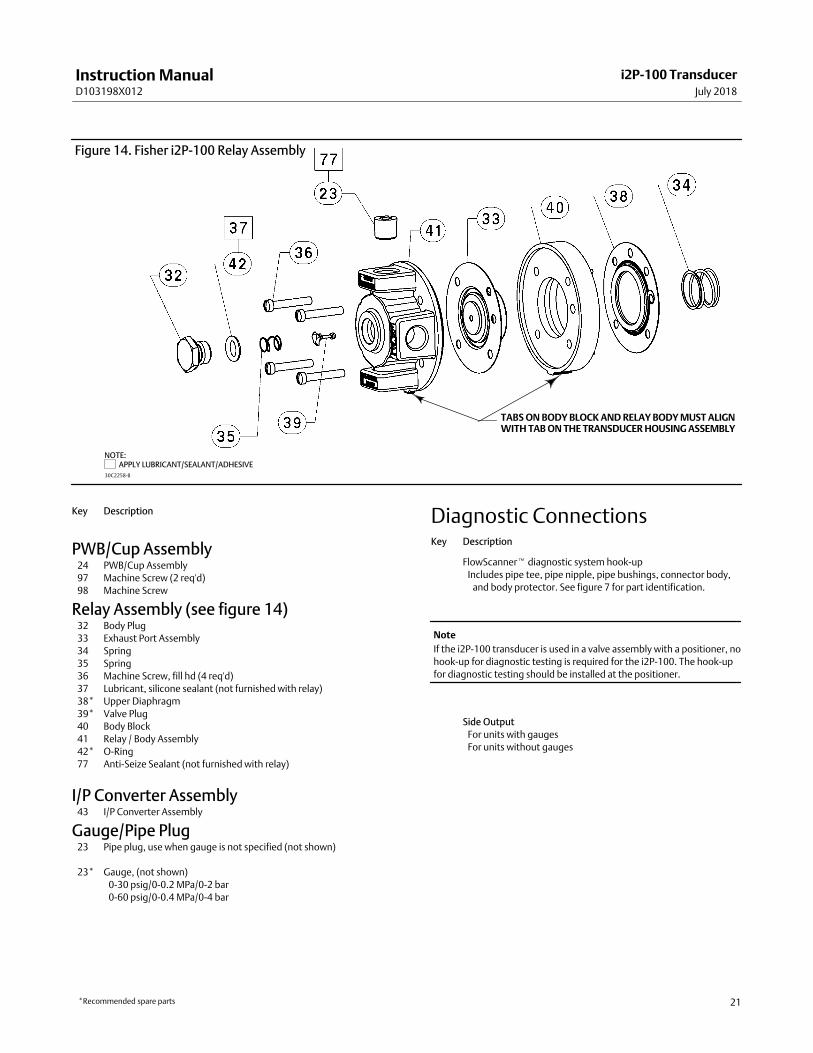
1. Assemble the inner valve spring (key 35) onto the body plug (key 32) and fit the valve plug (key 39) onto the innervalve spring as shown in figure 12. To assure best alignment between the valve plug, inner valve spring, and bodyplug; fit the valve plug onto the inner valve spring so that one of the three tabs at the base of the valve plug sets atthe end of the last coil of the inner valve spring.
2. Lubricate the O‐ring (key 42) with a silicone sealant (key 37). Insert the assembled valve plug, inner valve spring,and body plug into the relay body (key 41). Compress the spring and thread the body plug (key 5) into place. Then,tighten the body plug.
3. Insert two of the mounting screws (key 36) into two opposite holes of the relay body (key 41). Hold the screws inplace while assembling the following parts on the relay body. The screws serve as studs to align the parts as they arebeing assembled.
4. When replacing the exhaust port assembly (key 33), make sure all passages and screw holes are aligned and thatthe hole in the center of the exhaust port assembly fits over the valve plug (key 39). Place the exhaust port assemblyon the relay body (key 41). Hold assembled parts in place.
5. Make sure the tabs on the body block (key 40) align with the tabs on the relay body (key 41) and that the side with 5holes faces the relay body. Place the body block on the assembled parts. Hold assembled parts in place.
6. When replacing the input diaphragm (key 38), make sure all passages and screw holes are aligned. Place the inputdiaphragm on the body block (key 40). Hold assembled parts in place.
7. Install the bias spring (key 34) into the transducer housing assembly (key 1). Make sure the tabs on the body blockand relay body align with the tab on the transducer housing assembly. Place the assembled parts onto thetransducer housing assembly. Thread the two mounting screws (key 36) into the transducer housing assembly.Install the remaining two mounting screws. Tighten all mounting screws to 2 N�m (20 lbf�in).
8. Perform the procedure in the Calibration section of this manual.
Parts OrderingA serial number is assigned to each transducer and stamped on the nameplate. Always refer to this serial number whencorresponding with your Emerson sales office or Local Business Partner regarding spare parts or technical information.
WARNING
Use only genuine Fisher replacement parts. Components that are not supplied by Emerson Automation Solutions shouldnot, under any circumstances, be used in any Fisher instrument. Use of components not supplied by Emerson may voidyour warranty, might adversely affect the performance of the instrument, and could cause personal injury and propertydamage.
Parts KitsDescription Part Number
Repair Kit for i2P‐100 electro‐pneumatic transducer
Contains O‐rings (key 4, 9, 12, and 55) and
Filter/Restrictor assembly (key 10 & 11) R2P100X0032
Note:
Transducers Ordered Prior to November 2013
If you have not yet updated your PWB/Cup Assembly (key 24) and
require the low bleed 0.14 to 2.3 bar (2 to 33 psig) range you must
update your PWB/Cup Assembly using upgrade kit R2P100X0042.
Description Part Number
Upgrade Kit for i2P‐100 electro‐pneumatic transducer
w/Electronics Module for PWB/Cup Assembly
Contains O‐rings (key 4, 9, 12, and 55)
Filter/Restrictor assembly (key 10 & 11),
and PWB/Cup Assembly (key 24) R2P100X0042

Instruction ManualD103198X012
i2P-100 TransducerJuly 2018
20
Figure 13. Fisher i2P‐100 Transducer Assembly
NOTE: APPLY LUBRICANT/SEALANT/ADHESIVE
30C2230‐C
Parts List (see figure 13)
Note
Contact your Emerson sales office or Local Business Partner for Part
Ordering information.
HousingKey Description
�1 Housing
�2 Cover (2 req'd)
�3 Configuration Label
�4* O‐Ring(1) (2 req'd)
�6 Feed Thru (2 req'd)
Key Description
�7 Wire Retainer (2 req'd)
�8 Set Screw (2 req'd)
�9* O‐Ring(1)
�10 Restrictor, Primary(1)
�11* Filter(1)
�12* O‐Ring(1)
�13 Filter Cap
�14 Machine Screw (2 req'd)
�15 Flame Arrestor
�16 Flame Arrestor
�17 Lubricant, silicone sealant (not furnished with transducer)
�18 Thread locking adhesive, high strength (not furnished
�with transducer)
�55 O‐Ring(1)
�69 Nameplate
�70 Screw (2 req'd)
�71 Vent Assembly
�76 Pipe Plug
�102 Washer
*Recommended spare parts
1. Available in the Repair Kit
Instruction ManualD103198X012
i2P-100 TransducerJuly 2018
21
Figure 14. Fisher i2P‐100 Relay Assembly
30C2258‐B
NOTE: APPLY LUBRICANT/SEALANT/ADHESIVE
TABS ON BODY BLOCK AND RELAY BODY MUST ALIGNWITH TAB ON THE TRANSDUCER HOUSING ASSEMBLY
Key Description
PWB/Cup Assembly�24 PWB/Cup Assembly
�97 Machine Screw (2 req'd)
�98 Machine Screw
Relay Assembly (see figure 14)�32 Body Plug
�33 Exhaust Port Assembly
�34 Spring
�35 Spring
�36 Machine Screw, fill hd (4 req'd)
�37 Lubricant, silicone sealant (not furnished with relay)
�38* Upper Diaphragm
�39* Valve Plug
�40 Body Block
�41 Relay / Body Assembly
�42* O‐Ring
�77 Anti‐Seize Sealant (not furnished with relay)
I/P Converter Assembly�43 I/P Converter Assembly
Gauge/Pipe Plug�23 Pipe plug, use when gauge is not specified (not shown)
�23* Gauge, (not shown)
0-30 psig/0-0.2 MPa/0-2 bar
0-60 psig/0-0.4 MPa/0-4 bar
Diagnostic ConnectionsKey Description
FlowScanner� diagnostic system hook‐up
Includes pipe tee, pipe nipple, pipe bushings, connector body,
and body protector. See figure 7 for part identification.
Note
If the i2P‐100 transducer is used in a valve assembly with a positioner, no
hook‐up for diagnostic testing is required for the i2P‐100. The hook‐up
for diagnostic testing should be installed at the positioner.
Side Output
For units with gauges
For units without gauges
*Recommended spare parts

Instruction ManualD103198X012
i2P-100 TransducerJuly 2018
22
Key Description
Mounting Parts
Note
Contact your Emerson sales office or Local Business Partner for
information on ordering the following i2P‐100 mounting options.
Yoke Mounting
470 size 23 through 64
80 Mounting Bracket,
81 Washer (4 req'd)
82 Cap Screw (4 req'd)
480 Series actuator boss
80 Mounting Bracket
81 Washer pl (4 req'd)
82 Cap Screw (4 req'd)
83 Screw (2 req'd)
85 Mounting Bracket
86 Hex Nut (2 req'd)
585C size 25 and 50
80 Mounting Bracket
81 Washer (4 req'd)
82 Cap Screw (4 req'd)
83 Screw (2 req'd)
585C (470) size 60, 68, 100, and 130 ; 657 and 667 size 30, 34,
40, 45, 50, 60, 70, 80 & 87; 1051 and 1052 size 40, 60 and 70;
1061 all sizes
80 Mounting Bracket
81 Washer (4 req'd)
82 Cap Screw (4 req'd)
83 Screw (2 req'd)
84 Spacer
Key Description
Casing Mounting
657 and 667 size 30, 34, 40, 45, 50 and 60
80 Mounting Bracket
81 Washer (2 req'd)
82 Cap Screw (2 req'd)
83 Screw (2 req'd)
657 and 667 size 70
80 Mounting Bracket
81 Washer (2 req'd)
82 Cap Screw (2 req'd)
83 Screw (2 req'd)
1051 and 1052 size 20, 33, 40, 60 and 70
80 Mounting Bracket
81 Washer (2 req'd)
82 Cap Screw (2 req'd)
83 Screw (req'd)
1250 and 1250R all sizes
80 Mounting Bracket
81 Washer (2 req'd)
82 Cap Screw (2 req'd)
87 Washer
91 U‐Bolt (2 req'd)
92 Hex Nut (req'd)
Pipestand Mounting80 Mounting Bracket
81 Washer (4 req'd)
82 Cap Screw (2 req'd)
88 Pipe Clampl
Surface Mounting
80 Mounting Bracket
82 Cap Screw
Emerson Automation SolutionsMarshalltown, Iowa 50158 USASorocaba, 18087 BrazilCernay, 68700 FranceDubai, United Arab EmiratesSingapore 128461 Singapore
www.Fisher.com
The contents of this publication are presented for informational purposes only, and while every effort has been made to ensure their accuracy, they are notto be construed as warranties or guarantees, express or implied, regarding the products or services described herein or their use or applicability. All sales aregoverned by our terms and conditions, which are available upon request. We reserve the right to modify or improve the designs or specifications of suchproducts at any time without notice.
� 2005, 2018 Fisher Controls International LLC. All rights reserved.
Fisher and FlowScanner are marks owned by one of the companies in the Emerson Automation Solutions business unit of Emerson Electric Co. EmersonAutomation Solutions, Emerson, and the Emerson logo are trademarks and service marks of Emerson Electric Co. All other marks are the property of theirrespective owners.
Neither Emerson, Emerson Automation Solutions, nor any of their affiliated entities assumes responsibility for the selection, use or maintenanceof any product. Responsibility for proper selection, use, and maintenance of any product remains solely with the purchaser and end user.