fisher and paykel active smart refrigerators
TRANSCRIPT

Active Smart™
RefrigeratorsUSA
517775Fisher & Paykel Appliances © 2004 August 2004

2
Contents
1.0 Fault Code Display Status - (Stage 4.2)2.0 Thermistor Sensors Resistance Table3.0 Mode Status - Stage 4.24.0 Sensor Temperature Conversion5.0 PC Sensor Temperature6.0 FC Sensor Temperature7.0 Defrost Sensor Temperature8.0 Input / Output Status9.0 Download Data10.0 To Manually Force A Defrost11.0 Show Room Mode12.0 Special Option Mode (Israel)13.0 Wiring Diagrams14.0 Service Reference “B” Models15.0 Service Reference “T” Models16.0 Fault Finding Flow Chart - (Listing) A System Faults
B Temperature FaultsC Sensor FaultsD Auxiliary Faults

3
1.0 Fault Code Display Status - (Stage 4.2)
If a fault should develop in the temperature measurement system, defrostsystem, fans or low ambient heater, a fault code will be shown automatically onthe display and the fault audio alarm will sound. At the same time, the bottomL.E.D. will flash red alternately with the fault L.E.D pattern. When any controlbutton is pressed, the audio alarm is turned off, although the normal display isshown for 8 seconds before the fault code continues to flash.
To reset the audio alarm, disconnect the refrigerator from the power supply for afew seconds. If this is not done, the audio alarm will automatically reset after 72hours.
Fault codes will be in a binary code and the L.E.D.s that flash will have thefollowing binary values:
Note: The refrigerator goes through a sequence of tests whenever it is turnedon at the power supply or whenever the door is closed while it is on. It takes 20seconds to complete the test sequence, and opening a door will interrupt it. If,for example, there is a fault with the fans/low ambient heater connector at thepower module (it may be unplugged) and a door is opened as soon as the faultaudio alarm sounds, the fault code shown will be code 13 (low ambient heaterdrawing less current than expected). This is because the low ambient heater isthe first item tested and so the refrigerator will fault for this but carry on withmore tests.
128
1248
1632
64

4
If the doors are left closed until the tests are completed, the fault code shown willbe code 11 (the current measured for the ambient heater, PC fan and FC fan islower than expected). It is therefore recommended that if the fault audio alarmsounds as soon as the refrigerator is turned on, or as soon as the doors areclosed, the service technician should wait for 20 seconds before opening thedoor to check the fault code. This will allow the refrigerator to complete thesequence of tests and will ensure that the fault code displayed is the correct one.
Example fault code:
2
16
Values of the L.E.D.s displayed are 2 + 16 = 18. Fault code displayed is faultcode 18.
The faults and their respective fault code that can be checked and serviced inthe field are as follows:
Display Code: 1Reason: On the last power up, the power module failed its self-test.Primary Action: Replace power module.
Display Code: 2Reason: The previous 2 defrosts were aborted after 30 minutes.Primary Action: Check defrost heater assembly in the FC (refer Section 16.0
D1 Defrost Heater). If faulty, replace.

5
Display Code: 3Reason: The resistance of all the temperature sensors is outside the
normal range. (> 45K Ohms).Primary Action: Check the 6 way RAST connector at the power module.Secondary Action: Reterminate the 6 way RAST connector.Tertiary Action: Replace the power module.
Display Code: 4Reason: The resistance of all the temperature sensors is outside the
normal range. (< 660 Ohms).Primary Action: Check the 6 way RAST connector at the power module.Secondary Action: Reterminate the 6 way RAST connector.Tertiary Action: Replace the power module.
Display Code: 5Reason: The resistance of the FC sensor is outside the normal range.
(> 45K Ohms).Primary Action: Check the sensor connection at the power module.Secondary Action: Replace the sensor.
Display Code: 6Reason: The resistance of the FC sensor is outside the normal range.
(< 660 Ohms).Primary Action: Check the sensor connection at the power module.Secondary Action: Replace the sensor.
Display Code: 7Reason: The resistance of the evaporator sensor is outside the normal
range. (> 45K Ohms).Primary Action: Check the sensor connection at the power module.Secondary Action: Replace the sensor.

6
Display Code: 8Reason: The resistance of the evaporator sensor is outside the normal
range. (< 660 Ohms).Primary Action: Check the sensor connection at the power module.Secondary Action: Replace the sensor.
Display Code: 9Reason: The resistance of the PC sensor is outside the normal range.
(> 45K Ohms).Primary Action: Check the sensor connection at the power module.Secondary Action: Replace the sensor.
Display Code: 10Reason: The resistance of the PC sensor is outside the normal range.
(< 660 Ohms).Primary Action: Check the sensor connection at the power module.Secondary Action: Replace the sensor.
Display Code: 11Reason: The current measured for the ambient heater, PC fan and FC
fan is lower than expected.Primary Action: Check the 6 way fan/LAH RAST connector at the power
module.Secondary Action: Reterminate the 6 way fan/LAH RAST connector.Tertiary Action: Replace the power module.
Display Code: 12Reason: The current measured for the ambient heater, PC fan and FC
fan is higher than expected.Primary Action: Check the 6 way fan/LAH RAST connector at the power
module.Secondary Action: Reterminate the 6 way fan/LAH RAST connector.Tertiary Action: Replace the power module.

7
Display Code: 13Reason: Low ambient heater is drawing less current than expected.
Either the heater or wiring is open circuit or the heater isfaulty.
Primary Action: Check wiring and connections at both heater and powermodule.
Secondary Action: Check ambient heater resistance. If not within limits, replace.
Display Code: 14Reason: Low ambient heater is drawing more current than expected.
Either there is a short in the heater or wiring, or the heater isfaulty.
Primary Action: Check wiring and connections at both heater and powermodule.
Secondary Action: Check ambient heater resistance. If not within limits, replace.
Display Code: 15Reason: The PC fan is drawing less current than expected. Either the
wiring is open circuit or the fan is faulty.Primary Action: Check PC fan wiring and connections at both fan and power
module.Secondary Action: Check fan. If faulty, replace.
Display Code: 16Reason: The PC fan is drawing more current than expected. Either
the wiring is shorted or the fan is faulty.Primary Action: Check PC fan wiring and connections at both fan and power
module.Secondary Action: Check fan. If faulty, replace.
Display Code: 17Reason: The FC fan is drawing less current than expected. Either the
wiring is open circuit or the fan is faulty.Primary Action: Check FC fan wiring and connections at both fan and power
module.Secondary Action: Check fan. If faulty, replace.

8
Display Code: 18Reason: The FC fan is drawing more current than expected. Either
the wiring is shorted or the fan is faulty.Primary Action: Check FC fan wiring and connections at both fan and power
module.Secondary Action: Check fan. If faulty, replace.

9
2.0 Thermistor Sensors Resistance TableTemperature
(oC)Resistance
(K Ohms + 5%)-30.0 25.17-25.0 19.43-20.0 15.13-15.0 11.88-10.0 9.392-5.0 7.4810.0 6.0005.0 4.844
10.0 3.93515.0 3.21720.0 2.64425.0 2.18630.0 1.81735.0 1.51840.0 1.27445.0 1.07550.0 0.9106

10
3.0 Mode Status - Stage 4.2
To enter the diagnostic mode:
Press and hold the MODE button, then press the temperature UP button (thisenters the diagnostic mode).
This enters the PC sensor temperature status (refer Section 5.0).
Press the up button.
1 time = FC sensor temperature (refer Section 6.0).
2 times = Defrost sensor temperature (refer Section 7.0).
3 times = Inputs / outputs status (refer Section 8.0).
To enter the data down load mode:
Press and hold the MODE button while pressing the temperature UP button, (thisenters the diagnostic mode), then press the temperature DOWN button (thisenters the data down load mode).
To exit the diagnostic mode, press the MODE button. If not terminatedmanually, diagnostic mode will time out and go back to default display after 5minutes.
Note: The door alarms do not operate when the appliance is in diagnosticmode.

11
4.0 Sensor Temperature Conversion
To obtain the temperature of either compartment sensor or defrost sensor:
1. Enter the diagnostic mode (refer Section 3.0 - Mode Status) and scroll tothe appropriate sensor temperature.
2. Add up the binary number indicated by the L.E.D. light pattern (refer figureabove).
3. Subtract 40 from the result to get the temperature.
Example:
Add up the number corresponding to each L.E.D. which is on:
0.5 + 4 + 8 + 32 = 44.5
Subtract 40 from the result
44.5 - 40 = 4.5 oC
Hence the temperature is 4.5oC

12
5.0 PC Sensor Temperature
To read the PC sensor temperature:
1. Press and hold the MODE button while pressing the temperature UP button(this enters the diagnostic mode).
2. The current PC sensor temperature is displayed in a code form (referSection 4.0 Sensor Temperature Conversion).
3. Return to normal operation by pressing the MODE button.
CAUTION: In reading temperatures there is a need to enter the required modewhen the door is first opened as all temperature readings are only sensortemperature / air temperatures and these will change rapidly with the increase inair temperature as soon as the door is opened.

13
6.0 FC Sensor Temperature
To read the FC sensor temperature:
1. Press and hold the MODE button while pressing the temperature UP button(this enters the diagnostic mode).
2. Press the temperature UP button once. The current FC sensor temperatureis displayed in a code form (refer Section 4.0 Sensor TemperatureConversion).
3. Return to normal operation by pressing the MODE button.

14
7.0 Defrost Sensor Temperature
To read the defrost sensor temperature:
1. Press and hold the MODE button while pressing the temperature UP button(this enters the diagnostic mode).
2. Press the temperature UP button twice. The current defrost sensortemperature is displayed in a code form (refer Section 4.0 SensorTemperature Conversion).
3. Return to normal operation by pressing the MODE button.

15
8.0 Input / Output Status
To enter the input / output status tests:
1. Press and hold the MODE button while pressing the temperature UP button(this enters the diagnostic mode).
2. Press the temperature UP button three times. The current input / outputstatus is displayed (refer diagram above).
3. If a device is on or a door is open the respective L.E.D. lights up.
4. Return to normal operation by pressing the MODE button.
PC Fan on
FC Fan on

16
9.0 Download Data
To download data into your laptop:
1. Press and hold the MODE button while pressing the temperature UP button(this enters the diagnostic mode).
2. Press the temperature DOWN button once. A RED L.E.D. will show at thebottom of the temperature scale.
3. Place the INTERFACE PEN over the top of the RED L.E.D. until thedownloading has been completed.
4. Return to normal operation by pressing the MODE button.
Notes on data downloading:
An interface MK2 downloading pen is needed, part number 425930B, and theFISHER & PAYKEL Smart Tool diagnostic programme loaded on to a laptopcomputer.

17
10.0 To Manually Force A Defrost
Press and hold the MODE button while pressing the temperature DOWN button.Note there will be a delay of 2 minutes before the element starts to heat aftergoing into this mode.
Also, after the defrost is terminated, the compressor will stay off for 4 minutesbefore restarting and the fans will stay off a further 30 seconds after thecompressor has started.
NOTE: A defrost will not occur if the defrost sensor is above +8oC. The use of aphase plug and clip on amp meter in the power lead will indicate whether thedefrost element is drawing current.

18
11.0 Show Room ModeEnter the diagnostic mode (press MODE and temperature UP buttons together),then hold the temperature UP button only for three seconds. The Show RoomMode will be entered which turns off the normal system control leaving only thePC light operating with no door alarms. There will be a “long” beep and while thedoors are opened the LED display will go through an attention grabbingsequence unless buttons are pressed, at which time the display will respond asnormal. Eight seconds after the last button press the display sequence willcontinue. The mode may be exited by switching off the appliance at the mains.
12.0 Special Option Mode (Israel)The Active Smart refrigerator is fitted with a special option mode. Should thecustomer wish to disconnect the operation of the door switch they can do so. Toenter this mode the customer is required to push and hold the MODE button onthe display board for ten seconds.When the cabinet is in this special option mode the following will not operate:• The interior lights will not turn on when the PC door is opened.• There will be no set temperatures (LEDs) lights displayed on the display
module.• The door alarm will be disconnected and will not sound even if the doors were
to be left open.The customer may exit this mode at anytime by pushing and holding the MODEbutton for ten seconds.
If the mode is not exited manually by the customer, it will revert automaticallyafter 80 hours.
Note: When in the special option mode the Active Smart will operate as normalwithout the above being used.

19
13.0 Wiring Diagrams Stage 4 Power & Console Board (With Butter Conditioner)
Ω
ΩΩ
W
ΩΩ
ΩΩ

20
“B” Model Wiring RouteActive Smart Stage 4

21
“T” Model Wiring RouteActive Smart Stage 4

22
14.0 Service Reference “B” ModelsPC TOO COLDCold Crispers
* Ambient heater opencircuit
- Check continuity of element usingmultimeter.
Ice in crispers * PC fan fitted upsidedown
- Fan hub to be facing PC
* PC fan not going - Check voltage to plug, check wiringpolarity
* Air leakage base ductcover
- Seal with foam tape on duct dividerspigot
* PC sensor location - Remove insulation padColdCompartmentWarm Top
* PC fan not going - Check for mechanical obstruction- Check power to plug- Check polarity- Replace fan- Check for broken wires.
TotalCompartmentToo Cold
* FC fan not going - Check power to plug- Check for broken wires- Check polarity- Replace fan
* Short of gas - Check run percentage, if high,
check evaporator- Check fully flooded evaporator,
check for leak.
* PC sensor inaccurate - Check calibration of sensor ice point
using interface binary or refer tothermistor resistance table inservice manual.
23
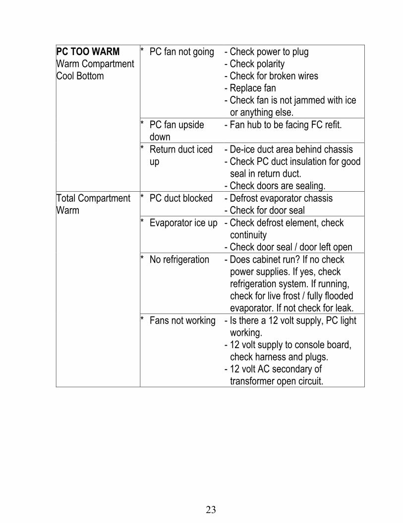
PC TOO WARMWarm CompartmentCool Bottom
* PC fan not going - Check power to plug- Check polarity- Check for broken wires- Replace fan- Check fan is not jammed with ice
or anything else.
* PC fan upsidedown
- Fan hub to be facing FC refit.
* Return duct iced
up- De-ice duct area behind chassis- Check PC duct insulation for good
seal in return duct.- Check doors are sealing.
Total CompartmentWarm
* PC duct blocked - Defrost evaporator chassis- Check for door seal
* Evaporator ice up - Check defrost element, check
continuity- Check door seal / door left open
* No refrigeration - Does cabinet run? If no checkpower supplies. If yes, checkrefrigeration system. If running,check for live frost / fully floodedevaporator. If not check for leak.
* Fans not working - Is there a 12 volt supply, PC lightworking.
- 12 volt supply to console board,check harness and plugs.
- 12 volt AC secondary oftransformer open circuit.

24
FC TOO COLDTotal Compartmenttoo cold
* FC sensor location - Check set temperatureSensor clipped and located in correctposition.
* Faulty sensor - Check calibration of sensor ice point
using interface binary or refer tothermistor resistance table in servicemanual.
* PC faulty sensor - Check PC cooling, fan runningFC TOO WARMBottom warm topfrozen
* Iced up evaporator - Check defrost element is working,replace if faulty. Check doors aresealing or have they been left open,adjust and advise customer. FC fanjammed, clear restriction, replace fanif necessary. Check defrost sensorposition, reposition onto chassis ifnot already there.
TOTAL CABINETTOO WARM
* No refrigeration - Does cabinet run? If no check powersupplies. If yes check refrigerationsystem. If running, check for live frost /fully flooded evaporator. If not, checkfor leak.
- Compressor is not running, check
power module voltage outputs. Checkcompressor and ancillaries .
- Check reed switches are working OK.FC COOLING PCWARMING
* Iced upevaporator
- Check defrost circuit continuity- Doors sealing, adjust- PC fan is running, if not refer PC too
warm
`* Iced up return
duct- De ice duct area- check PC duct insulation for good seal
in return duct- Check doors are sealing

25
ALARM ON * Defrost heater - Check console for any fault code- Check defrost element check
continuity- Check power module 230v output
* Sensors - Check console for fault codes
- Sensors above or below limit, referthermistor service table in servicemanual
* Alarm board fault - Check that PC / FC doors activatereed switches
- Check also reed switches with magnet- Check wiring harness to console
board* DC fan fault PC &
FC- Check open circuit- Check console for fault- Check diagnostics for fault- Check short circuit
* Ambient heater - Check open circuit- Check console for fault- Check diagnostics for fault- Check short circuit
FAULTDISPLAYED, NOALARM
* Console boardbut no alarmsounding
- Alarm has been switched off by user- Piezo alarm faulty on board, replace
board
LIGHT NOTFUNCTIONING
* Blown bulb - Check power supply to socket 7 volts,if nil check plug at board
- Check continuity of bulb, if nil replace
* Cabinet type - Console board not initialised, close FCdoor and press any button
* Poor connection - Spread halogen bulb legs
- Lamp holder, replace where possible- Connector on control module

26
CONSOLE NOLED LIGHTS
* Power module nopower
- Is there a 12 volt supply- 12 volt supply to console board
(Stages 1 to 3), check harness andplugs
- 12 volt AC secondary of transformeropen circuit
- Initialise cabinet.RASPBERRYNOISE
* Wrong consolemodule
- Initialise console module, close FCdoor and push any button on consolemodule
NOISY FAN PC * Ice around gasket - Replace assembly with new fan kit * Wires touching - Tuck wires away from fan blade * Faulty fan - Fit replacement
* Wires pulled tootight
- Re route wires
NOISY FAN FC * Ice on cover - Clear ice off cover and check doorsare sealing
* Ice on grill - Clear ice off grill and check doors aresealing
* Fan off mountings- Refit * Wires touching - Tuck wires away from fan blade
* Capillary touching - Shift capillary from fan area, make
sure it is not touching any part of thecabinet
* Fan motor noisy - Fit replacement * Wires pulled tight - Re route wiringICE BUILD UPCOMPARTMENT
* Doors sealing - Check gaskets are sealing, adjustgaskets
- Fit drain valve to drain tubeREFRIGERATIONNOISE
* Popping, farting - Evacuate recharge with ISCEON 49
* Gurgling,whistling
- Check alignment of capillary and applysound dampening tape

27
15.0 Service Reference “T” ModelsPC TOO COLDTotal CompartmentToo Cold
* FC fan not going - Check power to plug- Check polarity- Replace fan
* Short of gas - Check run percentage, if high check
evaporator- Check fully flooded evaporator,
check for leak
* PC sensor
inaccurate- Check calibration of sensor ice point
using interface binary or refer tothermistor resistance table inservice manual
PC TOO WARMTotal CompartmentWarm
* Evaporator ice up - Check defrost element, checkcontinuity
- Check door seal / door left open
* No refrigeration - Does cabinet run? If no, checkpower supplies. If yes, checkrefrigeration system
- If running, check for live frost / fullyflooded evaporator, if not check forleak
* Fans not working - Is there a 12 volt supply, PC lightworking
- 12 volt supply to console board,check harness and plugs
- 12 volt AC secondary of transformeropen circuit
- Check fan is not a Y97-16 stallingon fan speed 3
* Power module
failure- Is compressor running, is there a 12
volt supply from power module toconsole board (Stages 1 to 3). Ifnot, replace power module
* PC delivery ductblocked
- De ice area behind chassis

28
FC TOO COLDTotal CompartmentToo Cold
* FC sensor location - Check set temperature- Sensor clipped and located in correct
position
* Faulty sensor - Check calibration of sensor ice point
using interface binary or refer tothermistor resistance table in servicemanual
* PC faulty sensor - Check PC cooling, fan runningFC TOO WARMTotal CompartmentWarm
* No refrigeration - Does cabinet run? If no check powersupplies. If yes, check for live frost /fully flooded evaporator, if not checkfor leak
TOTAL CABINETTOO WARM
* No refrigeration - Does cabinet run? If no check powersupplies. If yes, check refrigerationsystem
- If running, check for live frost / fullyflooded evaporator
- If not, check for leak- Compressor is not running, check
controller voltage outputs- Check compressor and ancillaries
FC COOLING PCWARMING
* Iced up evaporator - Check defrost circuit continuity- Doors sealing, adjust- PC fan is running, if not refer PC too
warm

29
ALARM ON * Defrost heater - Check console for any fault code- Check defrost element, check
continuity- Check power module 230 volt output
* Sensors - Check console for fault codes
- Sensors above or below limit, referthermistor service table in servicemanual
* Alarm board fault - Check that PC / FC doors activatereed switches
- Check also reed switches withmagnet
- Check wiring harness to consoleboard
* DC fan fault PC &FC
- Check open circuit- Check console for fault- Check diagnostics for fault- Check short circuit
* Ambient heater - Check open circuit- Check console for fault- Check diagnostics for fault- Check short circuit
FAULTDISPLAYEDNO ALARM
* Console boarddisplay but noalarm sounding
- Alarm has been switched off by user- Piezo alarm faulty on board, replace
boardLIGHT NOTFUNCTIONING
* Blown bulb - Check power supply to socket 7volts, if nil check plug at board
- Check continuity of bulb, if nil replace
* Cabinet type - Console board not initialised, closeFC door and press any button.
* Poor connection - Spread halogen bulb legs- Lamp holder, replace where possible

30
CONSOLE NO LEDLIGHTS
* Power module nopower
- Is there a 12 volt supply?- 12 volt supply to console board,
check harness and plugs- 12 volt AC secondary of transformer
open circuitRASPBERRYNOISE
* Wrong consolemodule
- Initialise console module, close FCdoor and push any button onconsole module
NOISY FAN PC * Ice around gasket - Replace assembly with new fan kit * Wires touching - Tuck wires away from fan blade
* Faulty fan replace
assy with new fankit
- Fit replacement
NOISY FAN FC * Ice on cover - Clear ice off cover and check doorsare sealing
* Ice on grill - Clear ice off grill and check doorsare sealing
* Fan off mountings - Refit * Wires touching - Tuck wires away from fan blade
* Capillary touching - Shift capillary from fan area and
make sure it is not touching anypart of the cabinet
* Fan motor noisy - Fit replacement * Wires too tight - Re route wiringICE BUILD UPCOMPARTMENT
* Doors sealing - Check gaskets sealing, adjustgaskets
- Fit drain valve to drain tubeREFRIGERATIONNOISE
* Popping farting - Evacuate recharge with ISCEON49, check alignment of capillary
* Gurgling whistling - Check alignment of capillary andapply sound dampening tape

31
16.0 Fault Finding Flow Chart - (Listing)
A) System Faults
A1 Nothing in cabinet operatingA2 CompressorA3 Compressor running, but warm PC / FCA4 Console Fault CodeA5 No power to Power and Console modulesA6 Refrigerant System
B) Temperature Faults
B1 FC too cold, PC too warmB2 FC PC warmB3 Ice / Condensation formingB4 PC too cold
C Sensor Faults
C1 FC stratificationC2 PC stratificationC3 Defrost sensorC4 PC or FC sensor fault code
D Auxiliary Faults
D1 Defrost heaterD2 Door alarm operationD3 Fans - PC / FCD4 No LightD5 Low ambient heater

32
A. System FaultsA1 Nothing In Cabinet Operating
Versions 1 to 3
Replace powermodule

33
A2 Compressor

34
A3 Compressor Running, But Warm PC / FC

35
A4 Console Fault Code
(Versions 1 to 4.1)(Refer to section 2 for
fault codes forVersion 4.2)
36
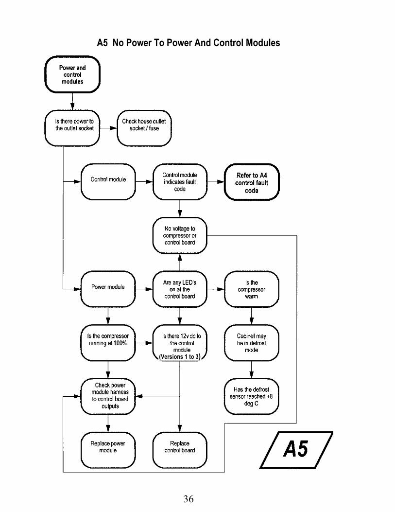
A5 No Power To Power And Control Modules
(Versions 1 to 3)

37
A6 Refrigerant System

38
B. Temperature FaultsB1 FC Too Cold, PC Too Warm

39
B2 FC / PC Warm

40
B3 Ice / Condensation Forming

41
B4 PC Too Cold

42
C. Sensor FaultsC1 FC Stratification

43
C2 PC Stratification

44
C3 Defrost Sensor

45
C4 PC Or FC Sensor Fault Code

46
D. Auxiliary FaultsD1 Defrost Heater

47
D2 Door Alarm Operation
Replace alarm board(Versions 1 to 3)
Replace controller

48
D3 Fans – PC / FC

49
D4 No Light

50
D5 Low Ambient Heater