fish protection screen guidelines for …wdfw.wa.gov/publications/00050/wdfw00050.pdf** 4/25/00...
TRANSCRIPT

** 4/25/00 DRAFT – Fish Protection Screen Guidelines (WDFW) – DRAFT 4/25/00 ** i
FISH PROTECTION SCREEN GUIDELINESFOR WASHINGTON STATE
April 25, 2000Washington Department of Fish and Wildlife

** 4/25/00 DRAFT – Fish Protection Screen Guidelines (WDFW) – DRAFT 4/25/00 ** ii
TABLE OF CONTENTS
Guidelines for Salmonid Habitat Protection and Restoration............................................. 1Acknowledgements............................................................................................................. 2Introduction......................................................................................................................... 3Fish Screen Concepts, Components and Nomenclature ..................................................... 4
Fish Screen Guiding Principles....................................................................................... 4Fish Screens: Types and Applications ........................................................................... 4
Rotary Drum Screens.................................................................................................. 5Vertical Fixed Plate Screen......................................................................................... 5Vertical Traveling Screen (panel and belt types)........................................................ 6Non-vertical Fixed Plate Screens................................................................................ 7Pump Screens, End-of-Pipe, Fixed Drum, Tee Screens ............................................. 9Infiltration Galleries.................................................................................................... 9
Fish Screen Design ........................................................................................................... 11Screen Design Criteria .................................................................................................. 11
Approach Velocity .................................................................................................... 12Screen Mesh – Materials and Minimum Openings................................................... 15Screen Face Material................................................................................................. 16Sweeping Velocity / Screen Orientation................................................................... 18Travel Time............................................................................................................... 19
The Fish Bypass System ............................................................................................... 19Bypass Entrance Geometry....................................................................................... 19Bypass Entrance Velocity and Bypass Flow ............................................................ 20Bypass Conduit and Drop Structures........................................................................ 21Delivery- The Outfall................................................................................................ 22
Structure Placement .......................................................................................................... 23Streams and Rivers ....................................................................................................... 23Canals............................................................................................................................ 23Lakes, Reservoirs, and Tidal Areas .............................................................................. 23
Debris Management .......................................................................................................... 25Debris Exclusion: Trash Rack ...................................................................................... 25Screen Cleaning Systems.............................................................................................. 25
Manual Screen Cleaning ........................................................................................... 26Screen Rotation......................................................................................................... 26Trolley Brush Cleaning............................................................................................. 26Jet Spray Cleaning .................................................................................................... 26Air Burst Cleaning .................................................................................................... 26
Pre-design Considerations ................................................................................................ 28Determining the Design Flow....................................................................................... 28Easements ..................................................................................................................... 28Construction Period ...................................................................................................... 29Agency Coordination .................................................................................................... 29
State Hydraulic Project Approval ............................................................................. 29

** 4/25/00 DRAFT – Fish Protection Screen Guidelines (WDFW) – DRAFT 4/25/00 ** iii
NMFS and USFWS Consultation ............................................................................. 30Consultation Submittals ............................................................................................ 30
Data Collection and Analysis............................................................................................ 31Site Survey .................................................................................................................... 31Flow Survey .................................................................................................................. 31Effectiveness and Compliance Monitoring................................................................... 33
Hydraulics ................................................................................................................. 33Biological Evaluation................................................................................................ 33
Operation and Maintenance .............................................................................................. 35Operation and Maintenance Manual ............................................................................. 35
Routine Maintenance ................................................................................................ 35Screen Submergence................................................................................................. 36Corrosion Control ..................................................................................................... 36Winter Operation ...................................................................................................... 36
Glossary ............................................................................................................................ 37Appendix A - Fish Screen Project Work Sheet ................................................................ 40Appendix B - Screen Operating Procedures Example...................................................... 41Appendix C – Fish screen sketches .................................................................................. 42Appendix D – sources of commercial screen products..................................................... 43Appendix E - Regional Fish Screen Criteria..................................................................... 44Appendix F - WDFW fish protection and technology development Policy ..................... 45
** 4/25/00 DRAFT – Fish Protection Screen Guidelines (WDFW) – DRAFT 4/25/00 ** 1
GUIDELINES FOR SALMONID HABITAT PROTECTIONAND RESTORATION
As part of Washington State’s salmon recovery strategy, the Washington State Departments of Fish andWildlife, Ecology, and Transportation, are currently developing guidelines for salmon habitat protectionand restoration. The standards and guidelines are a series of manuals, workshops, and other toolsaddressing various activities of salmon habitat protection and restoration and are intended to ensurecompliance with requirements of the federal Endangered Species Act and state salmon restoration policies.
This document is one of a series of documents that will make up the guidelines. Additional subjects forwhich guidelines have been (as of April, 2000) or will be developed are:
• Bank protection – Integrated Streambank Protection Guidelines is currently being developed.• Fish passage at road culverts – Fish Passage at Road Culverts is available.• Fishways guidelines are currently being developed.• Sand and gravel removal guidelines.• Estuary restoration guidelines.• Shoreline salmonids habitat restoration guidelines.• Freshwater habitat restoration guidelines.• Channel design guidelines.
The guidelines will be published on the web when complete. Parts of the guidelines will also be availableon the web as “works in progress” while they are still draft. Workshop opportunities will also be posted onthe web. These resources are located under technical assistance at http://www.wa.gov/wdfw/habitat.htm.

** 4/25/00 DRAFT – Fish Protection Screen Guidelines (WDFW) – DRAFT 4/25/00 ** 2
ACKNOWLEDGEMENTS
Funded by WDFW, SRFB, and WSDOT as part of a project developing Guidelines for Salmonid HabitatProtection and Restoration.
Authors Bryan Nordlund, Ken Bates
Edited by Tony Whiley

** 4/25/00 DRAFT – Fish Protection Screen Guidelines (WDFW) – DRAFT 4/25/00 ** 3
INTRODUCTION
Fish protection screens are devices installed at surface water diversions to physicallypreclude passage of fish into the intake and injury of fish at the intake. This documentpresents criteria and practical considerations for the design of fish protection screensincluding applications for hydroelectric facilities, irrigation, municipal, and industrialwater withdrawal projects. The major objective of the Fish Screen Guidelines is tohighlight important design elements that should be considered in the design of fishscreens at water diversion projects to provide the safe downstream passage of migratingjuvenile salmonids.
This document is a guideline only. It is intended to describe how to comply with specificdesign criteria or other fish protection requirements. Design criteria generally accepted byWashington Department of Fish and Wildlife (WDFW) and Northwest Region ofNational Marine Fisheries Service (NMFS) are included as a guide. Design criteria andrequirements for a specific site or facility should be verified directly with those agencies.Contacts are provided in Appendix X Fish Screen Contacts in Washington State. Theseguidelines cover common situations where fish screens are required; different oradditional requirements may be stipulated for specific installations.
This document refers to specific NMFS requirements. This document is not a NMFSdocument and therefore is not intended to be a comprehensive or necessarily currentreflection of policies or guidelines of that agency. Detailed NMFS and WDFW fishscreening criteria should be applied. They are available on the web athttp://www.wa.gov/wdfw/hab/engineer/fishscrn.htm and http://www.nwr.noaa.gov/1hydrop/nmfscrit1.htmrespectively. NMFS has additional specific pump screen criteria athttp://www.nwr.noaa.gov/1hydrop/pumpcrit1.htm.
There are many types of fish screens, designed for varying water withdrawal situations.However, they all share common design objectives; to allow the passage of water and thesafe and relatively unimpeded movement of fish. Both of these objectives can be metthrough careful design considerations. The National Marine Fisheries Service (NMFS)and the Washington State Department of Fish and Wildlife (DFW) have set specific fishscreen design criteria to protect juvenile salmonids. These criteria span the designprocess from screen materials, to hydraulic and biological considerations.

** 4/25/00 DRAFT – Fish Protection Screen Guidelines (WDFW) – DRAFT 4/25/00 ** 4
FISH SCREEN CONCEPTS, COMPONENTS ANDNOMENCLATURE
The following definitions should help the reader understand the following technical detailsections.
This section not yet written.
ExclusionEntrainmentGuidanceScreenApproach velocity, sweep velocityBypass
Fish Screen Guiding PrinciplesWe are using the concept of guiding principles in the guidelines for salmonid habitatprotection and restoration. Guiding principles are general statements that define theobjectives from which the specific guidelines are developed. The guiding principles thatare the basis of these fish protection screen guidelines are:
C Assume worst conditions of size of fish present (steelhead swim-up fry) andwater temperature;
C Use positive exclusion screening to approach 100% effectiveness.C Use voluntary guidance for migratory fish.C Use exclusion for non-migrating fish; must be able to voluntarily return upstream.C Return fish to channel.
These guiding principles are further described and developed throughout this guideline.
Fish Screens: Types and ApplicationsThe first step in the design process is identifying the type of screen and materialappropriate to a particular application. This section will discuss the most common typesof fish screens used in Washington and their typical applications and limitations. Thefollowing screen types are described in this guideline:
• Rotary Drum Screens• Vertical Fixed Plate Screen• Vertical Traveling Screen (panel and belt types)• Non-vertical Fixed Plate Screens• Pump Screens• End-of-Pipe Screens• Infiltration Galleries• Portable Screens
Fish protection screen applications vary from complex to simple. This guideline does notinclude all possible styles and details of screens. Most detail is provided for common and

** 4/25/00 DRAFT – Fish Protection Screen Guidelines (WDFW) – DRAFT 4/25/00 ** 5
complex situations such as mechanically cleaned screens in diversion canals. Less detailis provided for simple screens such as end-of-pipe screens. The reader must decide whichdetails are applicable to the specific facility and situation being considered. For example,details on screen bypasses are not relevant to an end-of-pipe screen submerged in areservoir. This guideline does not at this time include details of experimental devicessuch as Eicher or MIS screens or behavioral devices intended to protect fish.
Rotary Drum Screens
The rotary drum screen is a common type of fish screen in the Pacific Northwest (figure1). Water passes through screen mesh that covers a rotating cylinder. The greatestadvantage of the drum screen is that, through its rotation, it continuously removes debris.Debris is carried over the screen as it rotates and is washed off the screen on thedownstream side. Screen rotation is achieved by an electric motor, paddlewheel, solardrive, or hydraulic motor. It’s most current application is in open channel flowsituations, such as irrigation ditches. Using a single drum or multiples, rotary drumscreens can be used for a wide range of diversions and have been used in Washington atdiversions from as low as severalcfs and up to 3,000 cubic feet per second (cfs) or more.Drum screens are generally used in gravity diversion canals but can also be used todeliver water to pumping plants.The drum screen is very effective in protecting juvenile fish. Studies have found thatgreater than 98% of juvenile fish encountering a drum screen, designed by currentcriteria, survive (). A major design parameter for this screen type is its relativesubmergence. A submergence level between 65% and 85% of the screen diameter isappropriate. A greater submergence increases the potential for fish impingement andentrainment on the screen. At lower submergences, debris is not picked up on the face ofthe screen.
A disadvantage of the drum screen is, because of its movement, the wear of seals situatedon the screen’s side and bottom. The failure (or leakage) of the seals can result in fishimpingement. For this reason, these screens must be closely monitored and requiregreater maintenance in comparison to other screen types. A second major disadvantage isthe narrow range of submergence described above. For example, to maintain appropriatesubmergence for a four-foot diameter screen, the upstream water surface can vary nomore than 0.8 feet (20% of four feet or the difference between 65% and 85%submergence).
Vertical Fixed Plate Screen
The vertical fixed plate screen is also widely used in the Pacific Northwest (figure 2). Itis simply a vertical flat plate mesh. Fixed plate screens are commonly used for industrial,domestic water supply, and irrigation intakes both at pump and gravity diversions.
Advantages of the vertical fixed plate screen are that they are easy to seal, mechanicallysimple because there are no moving parts, and require a smaller civil works. For smalldiversions, these screens can be installed on the bank of a river and, therefore, require nobypass. Fixed plate screens are relatively simple to tightly seal since the mesh is fixed to

** 4/25/00 DRAFT – Fish Protection Screen Guidelines (WDFW) – DRAFT 4/25/00 ** 6
the structural frame and there are no moving parts or wear surfaces between the screenmesh and the structural frame. However, the removal of debris is an important designconsideration for this type of screen and may be more difficult than with a rotary drumscreen depending on the type of debris.
Vertical fixed plate screens require a mechanical cleaning system for debris removal.Commonly used cleaning systems include traveling brush cleaners and hydraulic back-spray systems; refer to the section on cleaning systems. The operation of the cleaningsystem operation is usually triggered by either a timing mechanism that operates thecleaner on a specific time interval or by head loss detection across the screen mesh, or acombination of both.
The flat plate screen can be built in a canal with much less blockage of the canal crosssection and flow compared to a rotary drum since screen support piers can be narrowcolumns instead of having to accommodate the drum diameter as in drum screenstructures.
Vertical Traveling Screen (panel and belt types)
Similar to the rotary drum screens, the mesh of vertical traveling screen rotates to removedebris collected on the screen face, depositing it on the downstream side (figure 3). Twotypes of vertical traveling screens are commonly used; panel-type screens, which haveindividual mesh panels, and belt-type vertical traveling screens which have a continuousbelt mesh. In common, both screens are driven by electric motors through a drive shaftat the top and rotate around a parallel idler shaft at the bottom. Vertical traveling screensare generally used for pump diversions.
The primary advantage of the belt screens is they can be installed in deep water. Thescreen can be built to any length within the structural capacity of the frame, drive, andshafts. Because the screen lifts vertically, there is no limitation on minimum or maximumscreen submergence to be effective.
Other advantages of the vertical traveling screen include that they can be installed on ariver bank, therefore, requiring no bypass; civil works are relatively compact; they areself-cleaned by rotation of the mesh, they can also be cleaned by jet spray cleaners orbrushes for additional cleaning action; and they are commercially available as a standardmanufactured product.
Vertical traveling screens have historically been built with horizontal troughs or ledgesbuilt onto the face of the screen. The purpose of the troughs is to lift debris and fish up asthe screen rotates. A high pressure spray bar near the drive shaft washes the debris into astationary trough on the deck of the structure. The debris can be collected there forremoval. The troughs are problematic for fish protection in that they preclude sealingbetween the face of the screen and the front of the screen frame at the bottom of thestructure.

** 4/25/00 DRAFT – Fish Protection Screen Guidelines (WDFW) – DRAFT 4/25/00 ** 7
Panel-type Vertical Traveling Screens
Many of the panel-type vertical traveling screens (Figure 4) are not specificallymanufactured for purposes of fish protection. For this reason, adapting them for fishprotection can be difficult. Many old installations of these screens do not exclude fishbecause of seal problems inherent in the design. The mesh seal problems are due to thedesign of the mesh panels that have hinges between them and must articulate when theyrotate around the idler shaft at the bottom of the screen. Seals often do not adequatelyclose the gap between the outer frame of the screen and the articulating rigid panels. Thissituation is hard to identify since the screen is often located in a sump.An advantage of the panel screens is that individual screen panels can be replaced asnecessary instead of replacing the entire screen mesh. A variety of screen mesh types andmaterials can be used.
Belt-Type Vertical Traveling Screens
As described above, the belt screen (Figure 5) has a continuous flexible chain mesh beltthat rotates around the drive and idler shafts. Stainless steel mesh is commonly used andthere have been successful application of plastic mesh. Disadvantages of the Belt-TypeVertical Traveling Screen are that the screen mesh can be deformed by flow if it is madetoo wide and not adequately supported from the backside, and as with the panel-typetraveling screen, there can be seal problems.
Plastic belt mesh has been installed experimentally on vertical traveling screens recentlyand appears to be a viable option to steel mesh.
Non-vertical Fixed Plate Screens
Other possible alignments of fixed plate screens include placing them horizontal orsloping; either upward or downward in the direction of the flow.
The advantage of these types of screens is that there are no moving parts and noadditional in-river diversion structures are required. Disadvantages include the method ofdebris removal may not be reliable. In addition, during low flow, fish are passed overshallow depth (or no depth) on the downstream end of the screen potentially causinginjury or impingement and therefore, the water surface must be raised to providesuccessful passage.
Downward Sloping Fixed Plate Screens
The downward sloping screens can either be flat plate (Figure 6) or a contoured platesuch as the Coanda screen (Figure 7). With this design, only a portion of the total flowtraveling across the screen passes through it. Flow passing through falls into a canalsituated below the screen. Fish are passed over the screen with the remainder of the flow.For this reason, the Coanda screens function effectively, in terms of fish passage, only ifsufficient flow depth exists at the downstream end of the screen ensuring continuousmovement of fish and debris over the screen. A minimum depth of water should be

** 4/25/00 DRAFT – Fish Protection Screen Guidelines (WDFW) – DRAFT 4/25/00 ** 8
provided over the entire screen face. That minimum should be based on expectations ofsize and type of debris, size and condition of fish passing, and potential changes in flowthat could reduce the depth to below the desired minimum. To satisfy these minimums, asubstantial amount of bypass flow might be required and they must be carefully operatedto ensure that the depth conditions are continuously satisfied. Downward sloping screensrequire at least several feet of head loss to operateThese two constraints limit theapplication of this type of screen. It is generally used for gravity diversions.
Flow distribution through the flat plate downward sloping screen is often not uniformsince the water depth over the upstream end of the screen is greater than over thedownstream end. This occurs obviously because water is removed from the column as itpasses over the screen. The extra depth at the upstream end provides additional head thatdrives more water through that portion of the screen. The extra depth and associated flowconcentration is often made worse by the hydraulics of the transition onto the screen.
Baffling systems have been placed behind the screen to distribute flow. Reliable andeasily operated baffling systems with a wide range of flow have not been developed.Downward sloping screens have been built in segments so, as the flow changes, more orfewer screen segments are operated. Gates upstream of each individual segments controlswater over that segment. Each segment is separated from adjacent segments by a shortdivider wall.
The Coanda feature helps correct the non-uniformity of flow distribution. The Coandashape is designed to follow more or less the nappe of water as if it were free spilling. Byfollowing that contour, the head driving flow through the screen can be more uniform. ACoanda shape can be optimized for one flow; the shape of the nappe will change as theflow changes.
Upward Sloping Fixed Plate Screens
Upward sloping screens (Figure 8) are the reverse of downward sloping screens; theirprofile rises in the direction of the water flow. Water does not drop through the screen;the screen is backwatered from below. Water drops over the downstream end of thescreen creating the fish and debris bypass. The downstream end of the screen mightnarrow gradually to reduce the bypass dimension and therefore the bypass flow. Thisstyle of screen is generally used for gravity diversions.
The primary advantage of this configuration is that there is more or less a uniform flowdistribution through the screen because the head differential is uniform throughout itsarea. The screen is relatively simple except for automatic cleaning devices.
A primary disadvantage is that debris is not automatically swept off the screen. It must bescraped off the screen into the bypass. Fish may reject the screen and the bypass. Therejection is often due to the low depth at the upstream and of the screen as it drops intothe bypass. Typically a depth of at least a foot is needed to keep fish from rejecting thebypass. Fish may also reject the bypass if the acceleration into it is too great. See thesection on bypasses.

** 4/25/00 DRAFT – Fish Protection Screen Guidelines (WDFW) – DRAFT 4/25/00 ** 9
The width should be at least eighteen inches and/or sufficient to pass debris likely to bepresent. There is little if any flexibility in upstream water surface elevation. If the waterlevel drops below the design water surface, the minimum bypass depth criteria is notsatisfied; if the water level rises, the excess water is put into the bypass system.
Upward sloping screens might be cleaned with mechanical brushes or air or water burstsystems. There is a risk of structural failure if the cleaning mechanism fails and theweight of the water overcomes the structural strength of the screen support frame.
Pump Screens, End-of-Pipe, Fixed Drum, Tee Screens
This is a group of screen styles built as a chamber attached to an end of a pipe. Theymight be box-shape or cylindrical. The walls are screen mesh and a suction pipe isattached to one wall. They range in size from one-cfs screens attached to small irrigationpumps to large tee-screen installations for fifty cfs or more. The advantages associatedwith the fixed drum screen are that they provide a good option for deep intakes, they aresubmersible, and can be equipped with air-burst or water jet cleaning systems. The fixeddrum screen is commonly used on the end of a pump intake in a pressurized system(Figure 9). An ideal use of the small pump intake screen, are small irrigation diversions.Many different screen configurations are commercially available. In addition, models areavailable commercially that meet juvenile salmonid criteria. Some models for smallscreens (up to 5 cfs) have very efficient water jet cleaning systems.
The disadvantages of this type of screen primarily concern the clearing of debris. Thefixed drum screen requires sufficient ambient water velocities to carry debris away fromscreen site, air burst cleaning systems, another cleaning system used with these screens,may not adequately remove debris accumulations especially from the bottom of thescreen.
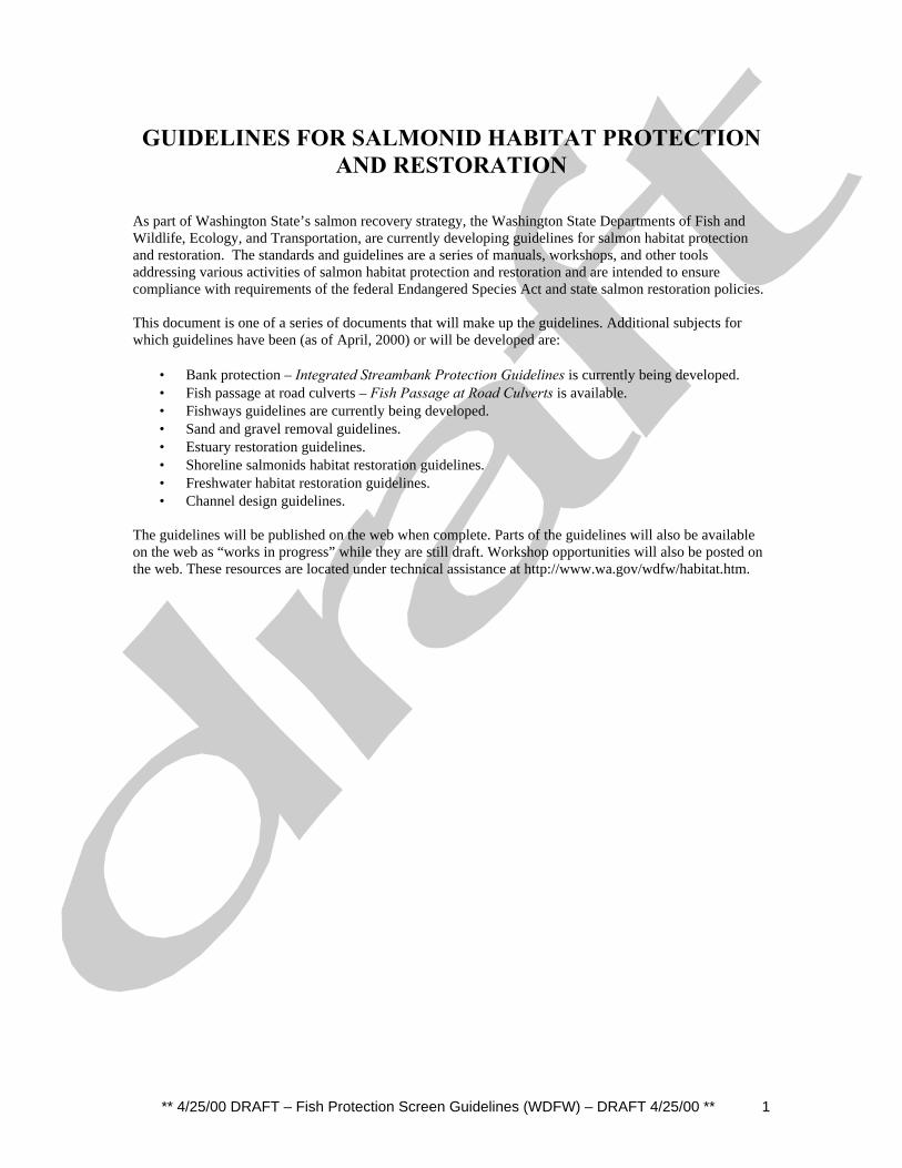
Infiltration Galleries
Infiltration galleries (Figure 10) are perforated pipe manifolds or single pipes buried in astreambed or bank. Water is drawn through the streambed or bank and into the pipe. Theyare installed in a steep section of a channel such as a riffle, which is maintained free offine sediment by the hydraulic action of the stream. It is necessary to be in a locationwhere the bed is regularly scoured and thereby cleaned rather in a depositional area suchas an artificial pool. Infiltration galleries are generally used for pump diversions but canbe use for gravity diversions in steep channels. The screen area is the area of thestreambed or bank through which the water flows rather than the area of the intake pipe.The streambed or bank is also the feature that acts as the fish exclusion device.
The primary advantage of infiltration galleries is, when successful, that the streamhydraulics rather than mechanical cleaning devices manages debris and sediment. Theprimary disadvantage is the risk of being plugged with sediment and/or debris. They areunsuccessful if the appropriate size distribution of sediment is not present, if excesssediment is moving at lower flows, or if constructed in a depositional or unstable stream

** 4/25/00 DRAFT – Fish Protection Screen Guidelines (WDFW) – DRAFT 4/25/00 ** 10
reach. Once plugged, they are not easily maintained since they are generally buried in thestreambed or bank. The failure rate of infiltration galleries is high; likely about 50%. Thefailures are generally due to a poor understanding of technical design requirements.
Infiltration galleries are usually associated with pump diversions though can be used atgravity diversions where there is adequate head to drive the flow.

** 4/25/00 DRAFT – Fish Protection Screen Guidelines (WDFW) – DRAFT 4/25/00 ** 11
FISH SCREEN DESIGN
Fundamental design considerations surrounding the screen are primarily hydraulic;controlling velocities and flows to eliminate impingement or entrainment of juvenilesalmon on the screen and to guide juveniles to the bypass system. Velocities surroundingthe screen are controlled by, among other factors, the screen orientation and the approachchannel configuration. Designing a screen facility based on the fish screen criteriadoesn’t guarantee that it will protect juvenile fish. In addition, and perhaps the mostcritical element of the fish screen design, is the implementation of an operations andmaintenance program. An effective operations and maintenance program ensures that theflows and velocities the screen were designed for are maintained, that debris collecting onthe screen face potentially leading to harmful velocities is cleared, and that seals are fishtight. Simply put, an effective operations and maintenance program ensures the screenoperates as designed, allowing water to flow through while fish are excluded and movedsafely downstream. These guidelines provide the framework to achieve both of theseobjectives. In this section pre-design considerations will be discussed. Screen designcriteria, which serve as the basis of the fish screen design are presented then designconsiderations for the bypass system. For screens located away from the parent streamdiversions, the bypass is route that delivers fish back to the stream. Then initialinformation needs and processes that must be confirmed prior to the advancement of theproject are listed.
Screen Design Criteria
Washington State Department of Fish and Wildlife and the National Marine FisheriesService have established fish screen design criteria to protect juvenile fish (salmonids) inproximity to screened water withdrawals from injury, migration delay, or mortality.Those criteria are included in Appendix X of this guideline. These criteria areconservative and are based on providing protection to the weakest swimming speciespresent, in their most vulnerable life stage, under adverse environmental conditions. Thisis the first of the fish screen guiding principles listed earlier; If protection can be providedat that level, it is expected that nearly all fish that encounter a fish screen designed bythese criteria will survive. It is recognized that there may be locations or times of theyear for which design for these conditions may not be warranted. It is common forconditions of fish size and water temperature to both be most severe at the same time andlikewise to both be less severe at other times. Unless conclusive data from studiesacceptable to Washington Department of Fish and Wildlife indicate otherwise, it isassumed that these extreme conditions exist at some time of the year at all screen siteswithin the state.The swimming ability of fish was the primary consideration in establishing the criteria.The screen hydraulics are designed to allow fish to voluntarily be guided and/or to escapethe screen. This is based on the second guiding principle; use voluntary guidance formigratory fish. Voluntary guidance means a fish is under control and able to voluntarilybe guided or move away from the screen. This minimizes the threat of impingement on orentrainment through the screen. Swimming ability, however, varies depending onmultiple factors relating to fish physiology, biology, and the aquatic environment. These

** 4/25/00 DRAFT – Fish Protection Screen Guidelines (WDFW) – DRAFT 4/25/00 ** 12
factors include: species, physiological development, duration of swimming time required,behavioral aspects, physical condition of the fish, water quality, and lighting conditions.Since conditions affecting swimming ability are variable and complex, screen criteria areexpressed in general terms and the specifics of any screen design must address on-siteconditions.
The primary design considerations of a diversion screen are all hydraulics; providing forthe passage of a sufficient quantity of water, consistently, with a minimum of head loss.The fish protection criteria impose no significant restriction on these fundamentals. Thecriteria are based on the control of velocities surrounding the screen. Screen approachvelocity, sweep velocity, bypass entrance velocity are the most critical hydraulicelements of fish protection at a screen. Their criteria will be discussed first followed byadditional design considerations for the control of screen velocities.
Approach Velocity
Physical contact with a screen may result in some level of injury to fish and, at worst,death. For this reason, the primary objective in the design of fish screens is to match theswimming ability and behavior of fish to the hydraulic characteristics of the screen andcivil works design to minimize the probability of contact with the screen. In other words,the screen is designed so it creates velocities low enough that fish can voluntarily keepthemselves from being impinged on or entrained through the screen. Studies of fishbiomechanics have led to hydraulic criteria used for approach velocity in fish screendesign (Smith, 1988).
The true velocity of the water moving towards a screen can be broken down into twovector components (Figure 11). The velocity component perpendicular to the screenface (rate of water moving through the screen) is known as the approach velocity. Theother component, the sweep velocity, is parallel to the screen face. Criteria are providedfor the approach velocity to avoid entrainment or impingement and the sweep velocity, tofacilitate guidance to the bypass or, if the screen is located in-channel, movement past thescreen.
The approach velocity is set at a level that is less than the sustained swimming speed ofjuvenile fish. Juvenile fish must be able to swim at a speed equal to the approachvelocity for an extended length of time to avoid impingement on the screen. The must beable to swim at a speed greater than that to escape the screen and return to the channelupstream. The criteria are set based on juvenile salmonid size and diversion surface watertype.
For screens in screens in streams, rivers, and canals with an ambient velocity (velocity ofthe water past the diversion structure) greater than 0.4 feet per second (fps), the approachvelocity criterion is 0.4 fps. For lakes and reservoirs where the ambient velocity is lessthan 0.4 fps, the approach velocity criterion is 0.33 fps. The ambient velocity in stillwater can be increased to the 0.4 fps by guide walls or other means within the structure ifthere is an adequate bypass to return fish to the reservoir or pass them downstream. For

** 4/25/00 DRAFT – Fish Protection Screen Guidelines (WDFW) – DRAFT 4/25/00 ** 13
the purposes of measurement and compliance, the approach velocity is considered to bethe velocity present three inches in front of, and perpendicular to the screen face.
At these levels nearly 100% of fry are protected. The criteria are maximum approachvelocities, levels that are not to be exceeded anywhere on the face of the screen. Theintake structure and/or fish screen shall be designed to assure that the diverted flow isuniformly distributed through the screen so the maximum approach velocity is notexceeded.
The approach velocity at a screen is calculated based on the effective screen area. Thistakes into account the area covered by seals and other potential obstructions and any areathat is not submerged. The effective area is the gross area of the screen, not the open areaof the mesh. The approach velocity is therefore calculated by dividing the screened flowby the effective screen area.
Sizing the Screen - Total Submerged Area
The screen area is determined based on meeting the approach velocity criteria. Tocalculate the required screen area (square feet) for or a screen in a canal with a requiredapproach velocity of 0.4 fps, divide the design flow (cubic feet per second) by themaximum approach velocity, 0.4 fps. The major assumptions of this design approach arethat the flow through the screen is uniform and that the screen is completely submerged.In other words, a minimum of 2.5 square feet of screen area is required for every cubicfeet per second of flow diverted through it.
A = Design Flow/Approach VelocityA = Screen AreaDesign Flow = Quantity of Water DivertedApproach Velocity = 0.4 ft/s
The area calculated is the effective screen area. The design should provide for anappropriate area of submerged screen surface throughout the entire range of divertedflows. It may be necessary to elevate the water surface at the screen face in a canal toensure that sufficient area is submerged. The water surface might be elevated by stop logsor control gates downstream of the screen The minimum required screen area must besubmerged during lowest stream flows and may not include any area that is blocked byscreen guides or structural members.
For rotating drum screens, the vertical projection of the screen area (the effective drumlength times the water depth at the face of the screen) is used to calculate the approachvelocity, as opposed to the circumferential screen area.
Approach Flow – Considerations and Adjustment
The flow approaching a screen can be controlled in some situations such as within acanal. There are four primary components that should be considered; velocity, turbulence,

** 4/25/00 DRAFT – Fish Protection Screen Guidelines (WDFW) – DRAFT 4/25/00 ** 14
flow distribution, and depth. There may also be specific constraints such as canalgeometry.
The velocity of the flow approaching the screen can affect sediment passage, successfuloperation of the bypass, and flow distribution through the screen.
Consider the sediment load that will be carried to the screen. How will flow patterns andvelocities created by the screen structure affect the transport or deposition of thematerial? What will be the effective geometry of the screen structure and flow patternswithin it after that material is deposited? The geometry of the screen should be designedto minimize unnecessary collection of sediment. Areas that will create still water oreddies should be eliminated. For screens within canals, the water velocity approachingthe screen should be maintained at a level to keep as much sediment suspended aspossible within the additional velocity limitations described here.
An assumption of the approach velocity criteria is that the flow coming to the screenstructure is laminar with parallel streamlines and uniform velocity. However,obstructions in the flow path upstream of the screen or abrupt transitions in the geometryof a canal or screen structure or bends in a canal can result in turbulence or non-uniformity in the true water velocity upstream of the screen and therefore variations inthe screen approach velocity and even flow reversals in extreme cases.
To promote uniform flow, the channel above a screen in a canal should be relativelystraight for at least a length equal to four times the width of the canal. If the true watervelocity is greater than 2.0 fps, the straight section should be longer. The canal cross-section should be fairly uniform for a similar distance upstream.When canal expansions are required to transition into the screen civil works, thetransition should be designed at an expansion rate of 1:8. For example, if the averagecanal width is 22 feet and the civil works provide a 24 foot wide approach canal, then theexpansion should begin at least 16 feet upstream of the civil works allowing for a twofoot expansion on each side of the ditch. This is to minimize head loss and turbulenceassociated with the expansion and to eliminate the potential for adverse hydraulicconditions at the screen face.
One method to alleviate areas of high concentrated flow and high velocity on the screen(“hot spots“) is to include an adjustable baffle system just downstream of the screenmesh. A baffle system is an array of bars, usually oriented vertically, that generallycontrol where flow passes through the face of the screen by adjusting the open spacingbetween them. Baffles may be required for the entire length of the screen if the flowdistribution approaching the screen is not uniform. Baffles are commonly needed on thedownstream two thirds of a screen face of large screen facilities (longer than about thirtyfeet) if the approaching flow is uniform to start with. If a screen layout is unique for aparticular site, a baffle system should be considered in the design or, at least, provisionsfor later installation if necessary.
If there is a large skew in flow across the channel, baffles will not be adequate to createthe appropriate distribution at the screen. In these situations, flow deflectors in the canal

** 4/25/00 DRAFT – Fish Protection Screen Guidelines (WDFW) – DRAFT 4/25/00 ** 15
upstream or a realignment of the approach channel might be necessary to correctapproach flow problems at a screen face.
The velocity of the flow approaching the screen can also affect velocity distributionthrough the screen. In an enclosed screen bay, flow with a high velocity has momentumthat can cause it to literally “pile up” as it is forced to slow at the downstream end of ascreen. The “piled up” super-elevated flow creates additional head at that portion of thescreen and therefore causes excess flow through that area. True water velocitiesapproaching screens in large installations should not exceed about 2.0 fps unless carefulconsideration of the flow distribution and possibly a physical model is used.
Debris accumulation on the face of a screen results in the loss of the screen’s effectivearea and therefore an increase in approach velocity. If allowances are not made in thedesign for debris accumulation (e.g.: sizing the screen conservatively using a safetyfactor) the approach velocity could exceed the criteria when debris accumulates. For thisreason, effective screen cleaning systems and the implementation of operations andmaintenance plans are what ultimately lead to the long-term safe passage of fish. Thesecomponents, as well as management of sediment and debris, are discussed in followingsections of this guideline.
Juvenile salmonids can sense rapid changes in velocity and tend to avoid moving fromlower to higher velocity and vice versa (Bell, 1984). Delays in fish migration can beavoided by maintaining the sweep velocity at a uniform level from the face of the screento the bypass. This is accomplished by the removal of all hydraulic obstructions alongthis flow path.
Depth considerations relate to screen submergence and are discussed above in the sectionTotal Submerged Area.
Screen Mesh – Materials and Minimum Openings
Mesh size criteria have been established for several screen face materials (table x) toprevent entrainment of fish. These criteria are based on the type of mesh material andthe size of juvenile salmonid expected to encounter the screen. (Juvenile salmon areconsidered “fry” if their fork length is less than 60 millimeters (mm), 2.4 inches and“fingerlings” if greater than 60 mm.) The mesh openings in Table X represent theminimum screen opening dimension in the narrowest direction.
Screen openings may be round, square, rectangular, or any combination of these forms,provided structural integrity and cleaning operations are not impaired. The following arethe maximum screen openings allowable for emergent salmonid fry. The maximumopening applies to features throughout the entire screen structure including the screenmesh, guides, and seals.
For woven wire mesh, the allowable opening is the greatest open space distance betweenmesh wires. An example allowable mesh specifications is provided; there are other

** 4/25/00 DRAFT – Fish Protection Screen Guidelines (WDFW) – DRAFT 4/25/00 ** 16
standard allowable openings available. The mesh specification gives the number of meshopenings per lineal inch followed by the gauge of the wires. For example, 6-14 mesh hassix mesh openings per inch of screen. It is constructed with 6, 14-gauge (0.080 inchdiameter) wires per inch. The profile bar criteria are applied to the narrow dimension ofrectangular slots or mesh.
Table x. Criteria for screen face material based on juvenile fish size.
Fry Criteria(less than 60 mm fork length)
Fingerling Criteria(greater than 60 mm fork
length)Perforated Plate(maximum opening diameter ormaximum slot width)
3/32 inch(2.38mm)
0.25 inch(6.35mm)
Profile Bar(maximum width opening)
0.069 inch(1.75mm)
0.25 inch(6.35mm)
Woven Wire (max. opening in the narrow direction)
0.087 inch(2.38mm)6-14 mesh
0.25 inch(6.35mm)
Minimum Open Area (%) 27 40
Screen Face Material
The three most commonly used screen mesh types used in this region and for whichcriteria are established include: perforated plate, profile bar, and woven wire (Figure 12).
Perforated Plate
Perforated plate is sheet metal stock punched with an array of holes in a variety ofconfigurations (Figure 12). Aluminum and stainless steel are generally used. It isavailable in a variety of widths but head loss should be considered if thick stock is used.Perforated plates are easy to work with, are relatively inexpensive, and handles floatingdebris well. The perforated plate mesh criteria for salmonid fry is 3/32 inch (2.38 mm)maximum opening and 27% open area.

** 4/25/00 DRAFT – Fish Protection Screen Guidelines (WDFW) – DRAFT 4/25/00 ** 17
Profile Bar
Profile bar is normally made from stainless steel bars welded parallel to each other on astructural backing and is available in a wide variety of openings and porosities (Figure12). It is a common commercial product with a variety of bar geometries, sizes and slotwidths between the bars. It provides the most structural capacity of common screen facematerial. It is also the most expensive material used as a screen mesh though the cost ofthe structural components behind the profile bar can often be substantially reduce whencompared to other screen face materials. Profile bar can be oriented either vertically orhorizontally along the screen face depending on the operation of the screen cleaningmechanism and the type of debris expected at a site. If a brush type cleaning system isused for debris removal, it should track in the same direction as the orientation of thelength of profile bars.
Profile bar is also available in cylindrical configuration for use as a pump intake screen.Profile bar porosity is calculated by dividing the bar opening by the sum of the baropening plus the bar width. The regional criteria for salmonid fry (x< 60 mm) protectioncalls for 0.069 in (1.75mm) maximum opening.
Woven Wire Mesh
Woven wire mesh, widely used as a screen face material, is available in a wide range ofwire gages (wire diameters), materials, and openings. Mesh opening and porosity forwoven wire mesh is calculated by:
M= (1-(n*g))/(n)P=((n*M)^2) *100
Where M= Dimension of mesh opening inchesP = Percent open areaN = number of openings per inchG = Wire diameter in inches.
For longevity and durability, minimum wire diameter for woven mesh should be 0.060inch (18 gauge) on fixed panel screens, where they are not subjected to impact by debris.Minimum wire diameter for woven mesh is 0.80 inch (14 gauge) for rotary drum screens,traveling belt screens, and in areas where there is a potential for damage from floatingdebris or during repetitive cleaning operations such as wearing against seals, debrisand/or sediment.
The regional criterion for salmonid fry (x<60mm) protection is 3/32 inch maximumopening and 27% minimum open area.
Head Loss Through Screen

** 4/25/00 DRAFT – Fish Protection Screen Guidelines (WDFW) – DRAFT 4/25/00 ** 18
Head loss through a screen is the difference in water levels upstream and downstream ofa screen. A large head loss can diminish the flow diverted through the screen or the headavailable for power generation in the case of a hydroelectric diversion. The head lossthrough a screen is negligible when the approach velocities and porosities recommendedhere are used. Through a wire mesh screen with an approach velocity of 0.4 fps, the headloss is about a quarter of an inch.
Accumulation of debris or ice or corrosion will increase the head loss as the open area isdecreased. When the head difference across a flat plate screen exceeds about two inches,debris becomes impinged more rapidly since the force of the head difference forces thedebris onto the screen. The structural capacity of the screen and screen frame must beconsidered and designed for some high head loss. The structural design of the screen willpartially depend on the risk of screen failure. The head loss used in the structural designmight vary from a few feet to a situation of a fully plugged screen and no water passingthrough it.
Sweeping Velocity / Screen Orientation
The orientation of a screen relative to the direction of the approaching flow directlyaffects the magnitude of the sweeping velocity component. For a definition of sweepingvelocity, see the section above on approach velocity. It is the sweeping velocity thatultimately guides juvenile fish to the bypass. One of the major objectives of a fish screendesign is to provide for the safe and efficient return of fish back to the river. Toaccomplish this, fish must be guided to a bypass that will carry them to the river. Toguide fish to a bypass the sweeping velocity component should be at least as great as theapproach velocity. This provides for effective guidance and reduces exposure time alongthe face of the screen. The sweeping velocity is adjusted by altering the screen anglerelative to the approach flow. For this reason, the screen should have a maximum angleof 45 degrees (relative to direction of the approaching) to meet criteria. At this angle, theapproach velocity is equal to the sweep velocity. Smaller angles provide a greatercomponent of sweep velocity to direct fish toward the bypass. Lower angles alsoincrease the true water velocity approaching the screen. See the section on ApproachFlow; Considerations and Adjustments for limitations.
The face of the screen should be smooth and uniform with no projections that wouldcreate turbulence or concentrations of flow through the screen. Special attention shouldbe given to screen end walls and seals.
The natural flow of a river will not necessarily create a sweeping velocity component ona large screen installed on a riverbank. A large screen diversion will affect the flowdirection of the river, especially at low flows. If a significant portion of the flow of theriver is diverted. In this situation, the flow entering the diversion may flow directly intothe screen rather than at the desired angle to create the sweeping component. To establishthe sweeping component, a guide wall may have to be constructed to make a geometrysimilar to an angled screen in a canal.

** 4/25/00 DRAFT – Fish Protection Screen Guidelines (WDFW) – DRAFT 4/25/00 ** 19
Travel Time
The criterion for the maximum exposure time for juvenile salmonids along a screen faceis 60 seconds. This criteria is set to limit potential impingement on the screen and isbased on stamina studies that found over 98% of the salmon fry tested were able to swimfor at least one minute at the approach velocity criteria. The sweep velocity should be ofsufficient magnitude to pass the entire screen face under the 60-second criteria. If this isnot possible, then the screen design should include intermediate bypass entrances.
The Fish Bypass System
A fish bypass system is a flow route designed to transport both juvenile and adult fishfrom the face of a screen back to the river and is necessary if the screen is not located inthe river itself. The bypass of in-river screens is the river itself if flow and fish are notcarried into an enclosed structure. The major components of a bypass system are shownin Figure 13. The bypass route should facilitate fish passage back to the main channel toa safe location with minimum risk of injury or delay. To accomplish this, design aspectsinclude guidance (moving the fish to the bypass and through the bypass channel), passage(transport through the system), and release to the main channel.
Screen bypasses often discharge into side channels through which swim adult fish. It maybe necessary to provide passage for adult fish upstream through the bypass, trash rack,and head gate structures. Adult fish passage criteria apply to each of these facilities inaddition to the screening criteria described in this guideline.
Bypass Entrance Geometry
The entrance to the bypass is one of the most critical elements of the entire screen design.It is the point with the highest concentration of fish in the entire facility. All of the fishthat are protected by the screen must freely and volitionally enter the bypass withoutdelay. Fish that reject the bypass will be further subjected to the diversion screen. Carefulconsideration should be given to the details of the bypass entrance to not create eddies,low velocity areas, rapid acceleration of the flow or other hydraulic disturbances thatmight delay fish passage.
The screen and bypass should be oriented so the screen terminates (at its mostdownstream end) at the bypass entrance and the flow approaching the screen is not forcedto turn as it enters the bypass.The width of the bypass entrance channel should be a minimum of 18 inches and itshould extend from the floor to the water surface. This width allows schooling fish toenter the bypass without delay. The bypass on large screens (greater than 200 cfs) shouldbe enlarged to several feet to minimize the likelihood of debris becoming lodged in thebypass opening and to allow light penetration further into the water column within thebypass.

** 4/25/00 DRAFT – Fish Protection Screen Guidelines (WDFW) – DRAFT 4/25/00 ** 20
Bypass Entrance Velocity and Bypass FlowJuvenile fish often delay or avoid passing through areas where the velocity decreases orincreases rapidly. The flow entering the bypass should accelerate slightly and gradually;it should not slow down. The bypass system should be operated such that the velocity atthe entrance is 10% greater than the true water velocity approaching it. The optimumpassage situation is where the bypass flow is controlled for various diversion rates so thevelocity is always 10% greater than the approaching velocity regardless of the flow in thecanal.
With the bypass entrance geometry and velocity provided as described, it is a simplecalculation to determine the bypass flow. Due to common uncertainties in the flowdistribution approaching a screen and in the hydraulic design of complicate bypasssystems, the bypass system should be designed for a flow 15% greater than the optimumdescribed here as a safety factor. In other words, the system should be designed with abypass entrance velocity 25% greater (115% of 110%) than the approaching true watervelocity.
The design bypass flow and bypass hydraulic capacity can then be calculated. Forexample, consider a four-foot diameter drum screen operating at 80% submergence, witha true water velocity of 1.0 fps approaching it and a bypass width of 18 inches. Thedesign bypass flow would be 5.3 cfs (4.0 ft x .80 submergence x 1.5 ft bypass width 1.0fps velocity x 1.1 acceleration).
The sensitivity of the bypass flow should be checked. Based on the expected true watervelocity and the geometry of the bypass, what is the bypass entrance velocity when thecanal water surface drops? A proper design accommodates all expected operatingscenarios. If the result is a bypass entrance velocity less than the true water velocityapproaching it, either the operating procedure or the designed geometry of the screenfacility should be modified.
The bypass flow carrying juvenile salmon should flow over a weir into a down well(Figure 13) or into a chute. In addition to allowing for precise flow measurement andadjustment, the weir traps juvenile salmonids and keeps them from re-entering the bypasschannel and forebay. Water spilling over a weir crest will create that trapping velocity.The capture velocity of steelhead smolts is about five feet per second. The weir shouldhave at least six inches of water depth over it to facilitate downstream juvenile and adultfish passage and debris passage. The depth can either be provided naturally by the bypassflow or the weir can be notched. It is common for the bypass flow to provide adequatedepth at the design operating point of the facility but the notch may have to be notched toprovide the depth when the diversion rate and bypass flows are at their minimums.
A good option to an overflow weir is a weir with a chute attached to the downstream side.The chute would be in place of a plunge into a downwell. The chute would tie directlyinto the bypass pipe. Since the chute provides a very efficient transition from the weircrest to the bypass, risk of fish injury due to turbulence and/or debris blockages withinthe downwell and entrance to the bypass pipe are minimized.

** 4/25/00 DRAFT – Fish Protection Screen Guidelines (WDFW) – DRAFT 4/25/00 ** 21
Since fish will avoid rapid increases in velocity, the velocity should be graduallyaccelerated up to a trapping velocity high enough they cannot escape. To control theacceleration a ramp should be built up from the floor at the bypass entrance to the crest ofthe bypass weir. The slope of the ramp should not be greater than 2:1. This, with thedepth of the water at the entrance, will determine the length of the bypass channel.Ramps in water depths less than about two feet are not likely practical.
Fish bypass flow requires positive hydraulic head differential between the water surfaceat the screen and the water surface at the bypass outfall to the stream.
Bypass Conduit and Drop StructuresThe bypass conduit is the facility that carries fish and debris back to the river. It mayinclude pipes, drop structures, channels, and flumes. Criteria for the bypass conduit andstructures are established to reduce the risk of injury to fish while being transported backto the river.. Smooth interior pipe surfaces and conduit joints are required to minimizeturbulence, facilitate the passage of debris, and reduce the risk of injury. Additionalcriteria include:
• Maximum velocity in the pipe should not exceed 30 feet per second[k18].• There should be no pumping of fish within a bypass system.• Bypass hydraulics should be open channel flow; bypass pipes should not be
pressurized.• There should be no extreme bends in pipes.[k19] Bypass pipe centerline
radius of curvature (R/D) shall be 5 or greater. (Greater R/D may berequired for supercritical velocities.)
• Bypass pipes or open channels should be designed to minimize debrisclogging and sediment deposition and to facilitate cleaning. The bypass pipediameter should be 24-inches (0.610 m) or greater. For screens passing 40cfs or less, the minimum bypass pipe diameter should be 10 inches (25.4cm).
• Closure valves are not allowed in the bypass pipe.• Depth of flow in a bypass conduit should be maintained at 0.75 ft (0.23m) or
greater. For screens passing 40 cfs or less, the minimum water depth in thepipe is 1.8 inches (4.6 cm) and is controlled by designing the pipe gradientfor minimum bypass flow[k20]. Nine inches of water depth should beprovided where downstream kelt passage is expected.
• Bypass system sampling stations should not impair normal operation of thescreen facility.
• There should be no hydraulic jumps within the bypass system.
Drop structures are often needed to get back down to the elevation of the river. A pipedesigned with the smoothness, flow, and depth criteria provided above will be at a verylow slope and therefore very long. Drop structures can be much more compact. Theyhave additional risk however of causing injury due to turbulence or from debris thatmight accumulate. The weirs of drop structures should be design similar to the bypassweir described above. A typical range in drop heights is 2 to 4 feet. Some cushioning

** 4/25/00 DRAFT – Fish Protection Screen Guidelines (WDFW) – DRAFT 4/25/00 ** 22
should be provided in the down well by countersinking the floor of the downwell at leastseveral feet below the minimum water surface.
Turbulence the downwells should be limited by providing a specific volume of waterbased on the energy to be dissipated in the pool.
Delivery- The OutfallThe last step of successful screening is returning fish to the river channel. Considerationsinclude safety of fish spilled from the bypass, deterring predation at the outfall, andattraction of adult fish to the bypass outflow.
To protect fish from direct injury, any outfall should be designed similar to downwellsdescribed above with appropriate volume for energy dissipation and buffer depth in thebottom of pools. Depth of pools must consider the likelihood of filling with river bedmaterial. Also, to protect fish, the impact velocity of the outfall nappe or jet should notexceed 25 fps. The impact velocity is the velocity of the bypass water striking the waterin the channel. The velocity limitation protects fish from damage due to shear betweenthe spilling water and the water in the receiving pool.
The outfall area should be selected and/or designed so it deters predation. Fish should bereleased into areas with strong downstream current and without eddies, reverse flow, orlikely predator habitat. The outfall natural river velocity should be at least 4.0 fps tominimize holding of predators. It may be difficult to satisfy both the pool release and thehigh velocity design preferences. In natural high gradient streams, the pool discharge isoften most critical. In large rivers, avoidance of predator habitat may be most critical.
Upstream migrating adult fish may be attracted to the bypass outfall especially if it has asignificant flow relative to the stream and the outfall is high velocity and/or plungingflow. Expect that fish will be attracted to it. Consider where they might leap at the outfalland minimize risk of them being damaged or stranded on the bank. Bypasses oftendischarge into side channels through which swim adult fish. It may be necessary toprovide passage for adult fish upstream through the bypass, trash rack, and head gatestructures. Adult fish passage criteria apply to each of these facilities in addition to thescreening criteria described in this guideline.

** 4/25/00 DRAFT – Fish Protection Screen Guidelines (WDFW) – DRAFT 4/25/00 ** 23
STRUCTURE PLACEMENT
The point of withdrawal is important for the hydraulic aspects of the screen as well as forthe protection of juvenile fish. Considerations may include whether to screen waterdirectly in the river channel or in a canal diverted from the river channel. Regardless, thescreened intake should be designed to withdrawal water from the most appropriateelevation, accommodating the expected range of water surface elevations, consideringjuvenile fish attraction, and appropriate water temperature control downstream. For riverscreens, it is preferable to keep the fish in the main channel avoiding the necessity of abypass at the screen.
Streams and Rivers
Optimally, and where physically practical, the screen should be constructed at the pointof diversion with the screen face parallel to river flow, aligned with the adjacent bankline. A smooth transition between the bank line and the screen structure is important tominimize eddies and undesirable flow patterns in the vicinity of the screen, flowsituations that can result in migration delays.
Physical factors that may limit screen construction at the diversion entrance includeexcess river gradient, the potential for damage by large debris, heavy sedimentation, orinappropriate flow conditions. Large streambank installations may require intermediatebypasses along the screen face to limit exposure to the screen. If it can be demonstratedthat flow characteristics, or site conditions, make construction or operation of fish screensat the diversion entrance impractical, screens can be installed in off-channel diversioncanals.
Canals
Screens constructed in canals and ditches should be located as close as practical to thediversion. Because flow is directed off the main channel, screens located in canalsrequire an effective juvenile bypass system designed to collect and safely transportjuvenile fish back to the river with minimal delay. This adds to the complexity of thescreen facility and underscores that, if possible, to have a screened withdrawal at thediversion point. Design elements of the bypass system are discussed in the BypassSystem section. The further away the screen is from the bypass, the more headdifferential there may be between the canal water surface and the river water surface andtherefore the more complex the design and operation of the fish bypass.
Lakes, Reservoirs, and Tidal Areas
Within lakes, reservoirs, or tidal areas, the withdrawal point should be located off shoreat depth where lower density of fish is expected. Salmon and trout fry generally inhabitshallow water areas near the shore. The intakes should be located where sufficientsweeping velocity exists to minimize sediment accumulation in and around the screen,facilitate debris removal, and encourage fish movement away from the screen face.

** 4/25/00 DRAFT – Fish Protection Screen Guidelines (WDFW) – DRAFT 4/25/00 ** 24
If a screened intake is used to route fish past a dam, the intake should be designed towithdraw water from the most appropriate location and elevation in order to provide thebest juvenile fish attraction to the bypass. Normally, the most attractive reservoir outlet isdesigned in combination with the normal reservoir outlet works. Such an outlet locationmay or may not comply with other objectives of achieving appropriate water temperaturecontrol for the downstream channel.

** 4/25/00 DRAFT – Fish Protection Screen Guidelines (WDFW) – DRAFT 4/25/00 ** 25
DEBRIS MANAGEMENT
Fish screens must have a reliable, fully functional, cleaning system capable of removingdebris from the entire mesh surface. It is important both to the passage of fish and thepassage of water that the cleaning system removes debris efficiently, completely, andultimately away from the screen mesh.The primary concern of inadequate screen cleaning is that debris may build on the screenface resulting in a loss of effective screen area. Greater flow then passes through theremaining clean screen area resulting in higher approach velocities. Because there is arelatively small tolerance for increases in approach velocity at most screens, debrisaccumulation can quickly result in impingement of juvenile fish. In some cases it hasbeen found necessary to specify sufficient screen area to create an approach velocity aslow as 0.1 ft/s to allow for some debris accumulation. This allows the screen to have asmuch as three quarters of its surface area blocked without creating localized areas wherethe approach velocities exceed 0.4 ft/s. A second concern is that debris accumulationscan block bypasses or trash racks, change hydraulics of bypass entrances that block fishmovement, or injure fish in high velocity areas such as bypass conduits. In addition toscreen and trash rack cleaning, the dimensions of trash racks, bypass entrances, andbypass conduits and the hydraulic design of bypasses are critical to debris management.They should be designed to minimize the capture of debris that should pass through theentire facility.
Debris Exclusion: Trash Rack
The primarily function of a trash rack is to collect larger debris that might damage thescreen or get blocked in the bypass system. A typical design is for a sloping(approximately 45 degrees into the flow) bar rack with a spacing of 6 to 12 inches. Thebar spacing may depend on type of debris encountered at the site. Bar spacing on trashracks should be at least 5 to 6 inches clear opening at fish screens. Spacing smaller than 3inches can cause delay or totally block passage of some juvenile salmonids. The closerspacing will also collect debris that could be passed through the entire system. The risk ofcollecting small debris at the trash rack is that the rack can become matted with materialnot leaving any route for juvenile fish passage. Left unmanaged, debris accumulations onracks can cause significant injury to fish passing through the debris, particularly if thedebris is an abrasive material such as tumbleweeds.
Trash racks that are so large that they cannot be cleaned manually at least daily should beequipped with an automatic rack cleaning device. Both a timer and a head loss controllershould actuate trash rack cleaners. For manual cleaning, an access walkway withappropriate safety rails is a necessary component of the design.
Screen Cleaning Systems
Several types of screen cleaning systems are described below. Regardless of the type ofcleaning system, a route must be available to pass debris downstream once it is removedfrom the screen face. Some screen designs incorporate a belt and hopper system to collect

** 4/25/00 DRAFT – Fish Protection Screen Guidelines (WDFW) – DRAFT 4/25/00 ** 26
and remove debris from the site. Failure to provide a debris escape route will allow debristo redistribute on the screen mesh eventually overwhelming the cleaning system. Sitehydraulics might also by itself provide or aid debris removal. A cleaner might move thedebris away from the screen and depend on currents to move the debris from the site.
Manual Screen Cleaning
Text yet to be written.
When the screen is cleared of debris manually, once or twice daily or at longer intervals,then additional screen area should be incorporated into the design. Debris should beremoved from bypass downwells, bypass pipe entrances, trash racks, and along the screenface.
Screen Rotation
Text yet to be written.
Trolley Brush Cleaning
Text yet to be written.Figure 14
Jet Spray Cleaning
Text yet to be written.
Jet spray cleaning is …Figure 15
With the jet type cleaner the mechanism is located on backside of the screen, out of theflow path. The disadvantage to the jet spray cleaner is that typically rotary cleaners don’treach the entire screen surface and heavy debris loads could require canal shutdown orscreen removal for cleaning. The effective area of the screen should be calculated as thecleaned area.
Water jet cleaning systems have been used successfully for fixed plate screens, pumpintake screens, and vertical traveling screens. They have been used as a supplementalcleaner on drum screens at sites with high debris loads. For drum screens, a spray bar canbe directed at an oblique angle towards the face of the screen to wash debris off the backside of the screen structure. The spray jets should cover the entire surface area of thescreen. Pressures from 30 to 100 pounds per square inch may be required for propercleaning action depending on the type and amount of debris present at the site.
Air Burst Cleaning

** 4/25/00 DRAFT – Fish Protection Screen Guidelines (WDFW) – DRAFT 4/25/00 ** 27
Air-burst cleaning systems (Figure 16( are commonly used with pump intake screens.This cleaning system has a variable performance record. With some applications air-burst cleaners have reportedly only removed debris from the upper part of the screen.This appears to be a distribution problem as air is taking a selective travel path throughthe screen.

** 4/25/00 DRAFT – Fish Protection Screen Guidelines (WDFW) – DRAFT 4/25/00 ** 28
PRE-DESIGN CONSIDERATIONS
Determining the Design FlowThe maximum expected diversion flow is fundamental to the design of fish screens andbypasses. In many cases this flow is the water right, certificate, or claim. In WashingtonState, water rights records are maintained by the Washington State Department ofEcology. If there is any uncertainty as to what the appropriate design flow is, the EcologyWater Resources Program should be consulted. Evidence of a legal water right or waterclaim should be submitted to WDFW during design consultation. See the Fish ScreenDesign Summary Form and instructions in Appendix X.
While the water right is a major design parameter, it is just a starting point. Thehydraulic design for a fish screen should also consider the potential range of flows aroundthe expected diversion flow. For instance, a diversion may just divert a fraction of thewater right for several months during much of the summer period. In drainages wherethe spring hydrology is determined by snow melt, the potential of flooding should also beconsidered. In flooding situations, the screen may have to withstand flows greatlyexceeding the water right, or design flow. The extreme range or variability in flows isbased on a certain risk of occurrence.If the maximum diversion flow is in question, a flow study is warranted before design canproceed. For minor projects, this may be a discussion with the water user concerning theirirrigation needs. For major projects, a formal flow study may be necessary involvinggaging sties, data recorders and flow measurements. In addition to the maximumdiversion flow, the rate of change of diversion flow may also be a design issue. In manysituations a rapid change in stream flow can affect the diversion flow, screensubmergence, bypass operation and/or screen approach velocity. If it is likely that suchchanges will occur unexpectedly or before the screen operator can make necessaryoperational changes, those change ranges must be included in the design. Flow rangesmight be accommodated by automating headworks, modifying headworks control orificesor gates, or by providing a wasteway in the canal to divert excess water back to the river.Operating a wasteway may not comply with project water rights.
EasementsIt is important to identify and obtain any necessary easements or property for theproposed screen early in the design process. Not having adequately completed this stephas created delays in the construction of a number of screen projects. When required,easements should be obtained for: 1) the construction access and staging, 2) operationsand maintenance access, 3) the screen site, 4) the bypass return line, 5) power lines, and6) trap boxes. Easement or separate operational agreements should clearly identifyresponsibilities and liabilities for operation of the screen facility.
If multiple parties are involved, easements or other operational agreements should clearlydefine responsibilities and liabilities for operation of screen facilities.

** 4/25/00 DRAFT – Fish Protection Screen Guidelines (WDFW) – DRAFT 4/25/00 ** 29
As common courtesy, all potentially affected property owners should be informed of theplanned screen. Those property owners directly affected by the project should, of course,be kept well informed of the project design and construction schedule.
Construction PeriodThe timing of construction, considering constraints of the water user(s) and allowable in-stream work periods is important to project planning. Usually, for irrigation diversions,there are periods when it is possible to construct a screen without affecting canaloperation. If a screen is to be constructed in a canal, in-water work periods may notapply, especially if the screen can be constructed in the dry.
This sort of information is easily obtained through consultation with water users. Theappropriate work window for in-stream work is best determined through consultationwith the Washington Department of Fish and Wildlife regional biological staff. Acontact list of area habitat biologist has been provided in Appendix X.
Often, a construction bypass must be constructed to divert around the new screenconstruction and maintain the diversion flow. In any case, WDFW and NMFS expect anyexisting screen and bypass system, or temporary replacement facilities, to be in operationthroughout the construction period.
Agency CoordinationWhen considering a site for a juvenile fish screen installation it is important for thedesigner to ensure that all interested parties have been contacted. Agencies interested inwater development projects involving fish screens include: the U.S. Fish and WildlifeService, National Marine Fisheries Service, Washington State Department of Fisheriesand tribal governments. Land use agencies such as the U.S. Bureau of LandManagement, U.S. Forest Service, Natural Resource Conservation Service, watermanagers and users (U.S. Bureau of Reclamation, water districts, irrigation districts),wetland protection agencies (Environmental Protection Agency, Army Corp ofEngineers) may also be important contacts. In addition, tribal and local governmentsshould be contacted. It is important to contact all potential interested agencies to see ifthey have interest or jurisdiction in a screening project, and also to provide their input asto what other agencies need to be involved. Neglecting the required contact with theappropriate agencies can delay construction due to unanticipated permit requirements. Iffederal funding is involved, certain processes may be required in the design process suchas Endangered Species Act consultation and National Environmental Policy Actcompliance. Appendix X includes a list of some Federal and State agency contactswithin Washington State.
State Hydraulic Project ApprovalA State of Washington Hydraulic Project Approval is required for any work that affectsthe flow or bed of the stream or that modifies the function of a fish screen. WashingtonState has a number of laws that apply to the necessity, design, and maintenance of fishscreens. RCW 77.16.220 indicates that any surface water diversion with the potential toentrain fish must have a fish screen. In addition, if necessary, the diversion must have a

** 4/25/00 DRAFT – Fish Protection Screen Guidelines (WDFW) – DRAFT 4/25/00 ** 30
means of returning diverted fish back to their waters of origin. RCW 77.16.210 statesthat persons or government agencies that manage in-stream structures must allow for thefree passage of fish. RCW 75.20.040 indicates the actions (penalties, remedies forfailure) taken by the state for entities failing to comply with RCW 77.16.220. RCW75.20.061 and RCW 77.12.425 state that the Washington State Department of Fish andWildlife Director can modify existing fishways and fish screens if they are foundinadequate without cost to the owner. The approval for a fish screen facility is theHydraulic Project Approval.
Designs must reflect the Northwest Regional Fish Screen Design Criteria (Appendix X).Backup information for consultation submittals and permit applications should besubmitted on the FishScreen Design Summary Form provided in Appendix X.
NMFS and USFWS ConsultationFor projects where the National Marine Fisheries Service (NMFS) or US Fish andWildlife Service have jurisdiction, such as FERC license applications and EndangeredSpecies Act consultations, a functional design, reflecting NMFS criteria, should bedeveloped as part of the application or consultation. Designs must reflect the NorthwestRegional Fish Screen Design Criteria (Appendix X).
Consultation SubmittalsDesign submittals should define the type, location, method of operation, and otherimportant characteristics of the fish screen facility. Design drawings should showstructural dimensions in plan, elevation, and cross-sectional views, along with importantcomponent details. Hydraulic information should include: hydraulic capacity, expectedwater surface elevations, and flows through various areas of the structures.Documentation of relevant hydrologic information is required. Types of materials mustbe identified particularly where potential contact with fish will take place. In addition, aplan of operations and maintenance procedures should be included.
Additional detail of operating plans are described later in this guideline. A Fish ScreenDesign Summary Form is also included in Appendix X.

** 4/25/00 DRAFT – Fish Protection Screen Guidelines (WDFW) – DRAFT 4/25/00 ** 31
DATA COLLECTION AND ANALYSIS
Site Survey
A topographic survey is necessary to determine the landscape characteristics of theproposed screen location. This information is used to determine optimal screen locationand facility layout and provides critical information necessary to design the screenhydraulics.
The survey should include the proposed point of diversion, screen area, bypass route,access routes, power availability. In addition to existing ground elevations, all man-madefeatures such as the diversion head gate, flow measuring weir, operational spillway, roadsetc. and any significant natural features (large trees, bedrock outcropping etc.) within theproject area should be located and described in the survey.
The site plan should describe and indicate the location of the project benchmark (verticalelevation control) and survey baseline (horizontal control) used to locate project features.
If the screen receives flow from a diversion canal, then the hydraulic characteristics ofthe canal should also be determined during the survey. Channel physical characteristicsimportant in flow modeling include the determination of the slope of the canal (above andbelow the screen) from the headworks to the screen, along with representative cross-sections (capacity) along its length. It is important to identify the ordinary high water (ortypical discharge water surface elevation) when conducting the cross-section surveys.
A Fish Screen Design Summary Form is also included in Appendix X with more detailfor the site survey.
Flow Survey
An understanding of the expected range in diversion flows is critical to the proper designof fish screens and bypass systems. Fish screen design is based on an expected watersurface elevation to provide proper screen submergence and bypass flow requirements.For this reason, all records of discharge should be obtained early in the design process.In instances where actual flow measurements are not available then the water right (claimor certificate) can be used as a starting point. But the full range in expected flow levelsshould be anticipated and incorporated into the screen facility design. The relationshipbetween discharge and water surface elevation must be established for the full range ofdiversion flows. At least one point can be determined during the initial survey. Timepermitting, a staff plate or water level recorder should be set into the canal diversion anda series of flow measurements taken over a period when the full range of flows areexpected. With time and data in short supply, Manning’s equation, calibrated with aseries of discharge/water surface elevation points, could be used to synthesize watersurface elevations over a greater flow range.

** 4/25/00 DRAFT – Fish Protection Screen Guidelines (WDFW) – DRAFT 4/25/00 ** 32
The relationship of water surface to stream flow must be established at the bypass outfalllocation. The extreme low and high flow situations and the dominant high flow situationduring the peak outmigration season are most critical. This information is most easilygathered by installing a water level recorder at the site for a winter to spring season andthen surveying a low flow point in the low flow season. This data must be correlated tostreamflow and flow frequency data.
The screen and bypass facility are initially designed based on the maximum diversionflow and the river flow expected the majority of the time. However, ultimately, thedesign should accommodate the full range of concurrent diversion and river flowsexpected. That is, through the full range of flow, the approach velocity criteria shouldnot be exceeded, the screen submergence must be within acceptable levels, and bypassflows maintained at a sufficient quantity to accommodate fish passage at the low flows.
A Fish Screen Design Summary Form is also included in Appendix X with more detailfor the flow survey.

** 4/25/00 DRAFT – Fish Protection Screen Guidelines (WDFW) – DRAFT 4/25/00 ** 33
Effectiveness and Compliance Monitoring
Hydraulics
Following the construction of a fish screen facility, water velocities should be measuredat critical locations to determine whether it is operating as designed. Important velocitypoints include a determination of flow and velocity at the upstream end of the screenfacility, along the entire screen face, and at the entrance to the bypass channel.
To examine the approach velocity, true water velocity measurements should be takenthree inches in front of the screen face. The angle of the flow at that point is alsomeasured so the approach and sweeping velocity components can then be calculated. Thedirection of flow can be recorded with a vane attached to a rod or frame. Eventually aseries of measurements should be taken across the entire screen (approximately every twofeet) at several points through the water column beginning about a half foot below thewater surface and then at approximately quarter depth points below that. Moremeasurements should be taken in locations where more complex flow situations occur forinstance, near piers and at the screen edges. If flow distribution baffles are included inthe facility, a less precise hydraulic survey may be done initially to optimize the baffles.If there are no flow distribution baffles and it is determined that the approach velocityand bypass flow are not at design levels, then the installation and adjustment of a bafflesystem may be necessary.
The canal should be initially operated throughout its diversion range to verify that thescreen submergence and other hydraulic design criteria can be satisfied. Staff gaugesshould be installed at the control points (i.e. bypass weir) so fast and accurate flowadjustments can be made. Staff gauges should be placed both immediately upstream anddownstream of flow control structures, within operator view, and in hydraulically stableflow. Staff gauge datums and readings and flow control operations must be checked withthe operations manual to verify accuracy of the manual.
Prior to any major hydraulic testing, a study plan must be developed in consultation withthe interested agencies.
Biological Evaluation
Once hydraulic testing is complete and the screen is operating as designed, biologicaltesting can be conducted. Biological testing examines how successful the screen facilityis in passing juvenile salmonids with success evaluated by fish passage time and health.Biological testing is necessary for screen styles and configurations for which extensivebiological evaluations have not previously been conducted or where uniquecharacteristics make previous evaluations irrelevant.

** 4/25/00 DRAFT – Fish Protection Screen Guidelines (WDFW) – DRAFT 4/25/00 ** 34
The main points for biological evaluation are passage past the screen and through thebypass. Elements of passage commonly include entrainment through the screen,impingement on it, and fish health through the entire screen system. Timing of passagethrough system might also be required in large installations. An method commonly usedfor screen evaluations is the mark recapture technique. Fish are marked such as anadipose fin clip. Depending on the numbers of juveniles moving past the screen, markingmay not be necessary. A common evaluation procedure is to then capture the releasedfish in a screened collection box downstream of the bypass outfall and at a point wherethere is minimal risk of damage to the fish. Initially, an overall facility examinationshould be made; releasing fish upstream of the facility and capturing them at the end ofthe bypass. If problems are identified, a closer examination should be undertaken.
Fish health is based primarily on a visual examination of scales and fins for damage thatmight have been caused by the screen or other obstructions. Periodic biological testingafter the initial test period might be recommended to identify any problems that developover time.
Prior to any biological testing, a study plan must be developed in consultation with theinterested agencies.

** 4/25/00 DRAFT – Fish Protection Screen Guidelines (WDFW) – DRAFT 4/25/00 ** 35
OPERATION AND MAINTENANCE
Once built, all facilities should have an operations and maintenance plan to ensure,among other considerations, the proper adjustment of flow through the screen and bypass,the clearing of debris, and checking of seals. For a fish screen to adequately serve itsfunction of protecting fish, attention to operational detail is necessary.
Operation and Maintenance Manual
An operations manual should serve as a reference to operating and managing the fishscreen facility. Providing concise operating criteria for a screen site also ensures that,despite personnel changes, the facilities operation doesn’t change. An example operationmanual for a paddlewheel drum screen is provided in Appendix X.
All the relevant hydraulics information should be included in the manual. Thisinformation includes rating curves (water surface and flow relationships) for the variousstaff gauges, bypass flow requirements, and screen submergence. All operations shouldbe based on staff gauges or marks on the facility or other easily identified parameters.The operations manual should also include a schedule for routine maintenance of specificcomponents of the screen facility.
Routine Maintenance
The components of the screen facility requiring routine maintenance might include:
Seals - Screen seals must be checked frequently for wear, and for debris that might betrapped by the seals.Debris accumulation / Cleaning Systems – Large material should be removed from thetrash rack and the screen cleaning system must be checked frequently to ensure it isworking properly.Sediment Removal - A method employed to remove sediment from a screen forebay is totemporarily reduce flow through the screen and open the bypass return pipe fully, tosluice sediment away from the site. Sediment should be removed from the forebay of thescreen site before it starts passing through the seals. Sediment should only be sluicedduring high streamflows. Sediment may have to be removed mechanically where there isany risk of it affecting habitats or fish in the stream. Detailed sediment managementprescriptions may be included for specific sites.Moving components should be greased (with environmentally benign grease) on a regularbasis.
When it is necessary to drain the canal for maintenance or at the end of the irrigationseason fish in the canal must be directed back to the river. If a canal is sloped sufficientlyand drains completely, fish can be routed out the bypass. This requires that the canal bedrawn down gradually. Depressions in the canal or structure where fish might becomestranded should be inspected and fish might have to be carried or herded to the bypass.

** 4/25/00 DRAFT – Fish Protection Screen Guidelines (WDFW) – DRAFT 4/25/00 ** 36
The application of herbicides and pesticides, as part of a routine facilities maintenance,has the potential to harm juvenile salmonids. Care must be taken to ensure that there isno possibility for any toxicant to be released into areas where it might come in contactwith fish or wildlife. It is important to develop a plan for the application of toxicantsshould they be necessary. The plan might include: 1) notifying fish and wildlifeauthorities before application, 2) salvaging or bypassing fish from a ditch prior toapplication, and 3) ensuring all gates and valves are closed so no possibility of leakageinto the riverine environment is possible. In the case of an irrigation canal, herbicidesshould only be applied when the canal is dry thereby avoiding any potential harm tofisheries resources.
Screen Submergence
If the river level or diversion flow changes, adjustments must be made as necessary toensure that the screen is properly submerged for the amount of flow being diverted.Bypass flow levels should also be adjusted at that time. The bypass pipe entrance andexit should also always be checked during each site visit.
The percent of submergence should be painted at a prominent location on the screen.This allows the water surface elevation to be verified at a glance. Some sites, especiallythose with large diverted flows, will require staff gages to verify proper water surfaceelevation and screen submergence.
Corrosion Control
A corrosion control system for a fish screen can significantly increase the life of afacility. Providing isolation of dissimilar metals will prevent the electrolysis process thatresults in corrosion. Neoprene washers and silicon bolt sleeves should be used whenattaching mesh to the structural frame of the screen. Sacrificial anodes are also be used atsites with corrosion potential. These are welded directly to the screen frame and work byproviding a more attractive location for electrolysis to occur and produce corrosion.Another potential cause of corrosion occurs when electric motors are grounded to thescreen frame. Stray currents produce minute charges in the frame sometimes increasingthe potential for electrolysis to occur.
Winter Operation
In some locations freezing conditions have to be considered for screen operation duringwinter months. Ice can quickly clog screens, causing loss of flow to the diversion. Somescreens are located in heated enclosures, if the full diversion flow is needed in coldweather situations. Another technique that has been used successfully to provide smallamounts of winter stock-water, is to allow the canal to freeze at full canal flow. After thewater surfaces freezes with a solid layer of ice, the canal flow is reduced to lower stockwater flow and the frozen upper layer remains in place to help insulate the flow beneathit. Before doing this cleaning mechanisms and drum screen drives must be disconnected.
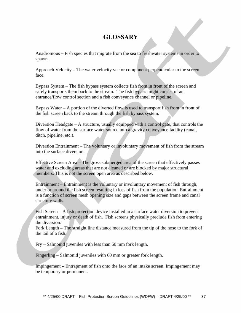
** 4/25/00 DRAFT – Fish Protection Screen Guidelines (WDFW) – DRAFT 4/25/00 ** 37
GLOSSARY
Anadromous – Fish species that migrate from the sea to freshwater systems in order tospawn.
Approach Velocity – The water velocity vector component perpendicular to the screenface.
Bypass System – The fish bypass system collects fish from in front of the screen andsafely transports them back to the stream. The fish bypass might consist of anentrance/flow control section and a fish conveyance channel or pipeline.
Bypass Water – A portion of the diverted flow is used to transport fish from in front ofthe fish screen back to the stream through the fish bypass system.
Diversion Headgate – A structure, usually equipped with a control gate, that controls theflow of water from the surface water source into a gravity conveyance facility (canal,ditch, pipeline, etc.).
Diversion Entrainment – The voluntary or involuntary movement of fish from the streaminto the surface diversion.
Effective Screen Area – The gross submerged area of the screen that effectively passeswater and excluding areas that are not cleaned or are blocked by major structuralmembers. This is not the screen open area as described below.
Entrainment – Entrainment is the voluntary or involuntary movement of fish through,under or around the fish screen resulting in loss of fish from the population. Entrainmentis a function of screen mesh opening size and gaps between the screen frame and canalstructure walls.
Fish Screen – A fish protection device installed in a surface water diversion to prevententrainment, injury or death of fish. Fish screens physically preclude fish from enteringthe diversion.Fork Length – The straight line distance measured from the tip of the nose to the fork ofthe tail of a fish.
Fry – Salmonid juveniles with less than 60 mm fork length.
Fingerling – Salmonid juveniles with 60 mm or greater fork length.
Impingement – Entrapment of fish onto the face of an intake screen. Impingement maybe temporary or permanent.

** 4/25/00 DRAFT – Fish Protection Screen Guidelines (WDFW) – DRAFT 4/25/00 ** 38
Open Screen Area – The area of all open slots, mesh or perforations on the screenavailable for the free flow of water.
Screen Entrainment – The voluntary or involuntary movement of fish through, under oraround the fish screen resulting in loss of fish from the population. Entrainment is afunction of screen mesh opening size and gaps between the screen frame and canalstructure walls.
Salmonid-
Surface Water Diversion – A man-made structure or installation for diverting water froma stream, river or other surface water body for a beneficial purpose (municipal, industrial,agricultural, hydroelectric generation, etc.) Surface diversions fall into two generalcategories: gravity and pump.
Sweeping Velocity – The component of approaching true water velocity that movesparallel to the face of the screen. It is a function of screen orientation, and the amount offish bypass flow and geometry of the approach channel.
True Water Velocity – The actual velocity of water rather than vector components of it.

** 4/25/00 DRAFT – Fish Protection Screen Guidelines (WDFW) – DRAFT 4/25/00 ** 39
Bibliography
Bell, M.C. 1991. Fisheries Handbook of Engineering Requirements and BiologicalCriteria, Fish Passage Development and Evaluation Program. U.S. Army Corp ofEngineers, North Pacific Division. Portland, OR.
Clay, C. H. 1995. Design of Fishways and other Fish Facilities. Lewis Publishers. 2ndEd. 248pp.
Pearce, R.O., R.T. Lee. 1991. Some Design Considerations for Approach Velocities atJuvenile Salmonid Screening Facilities. American Fisheries Society Symposium 10: pp237-248.
Smith, L.S., L.T. Carpenter. 1987. Salmonid Fry Swimming Stamina Data for DiversionScreen Criteria. Final Report to Washington State Departments of Fisheries and Wildlife.217 pp.

** 4/25/00 DRAFT – Fish Protection Screen Guidelines (WDFW) – DRAFT 4/25/00 ** 40
APPENDIX A - FISH SCREEN PROJECT WORK SHEET

** 4/25/00 DRAFT – Fish Protection Screen Guidelines (WDFW) – DRAFT 4/25/00 ** 41
APPENDIX B - SCREEN OPERATING PROCEDURESEXAMPLE

** 4/25/00 DRAFT – Fish Protection Screen Guidelines (WDFW) – DRAFT 4/25/00 ** 42
APPENDIX C – FISH SCREEN SKETCHES

** 4/25/00 DRAFT – Fish Protection Screen Guidelines (WDFW) – DRAFT 4/25/00 ** 43
APPENDIX D – SOURCES OF COMMERCIAL SCREENPRODUCTS

** 4/25/00 DRAFT – Fish Protection Screen Guidelines (WDFW) – DRAFT 4/25/00 ** 44
APPENDIX E - REGIONAL FISH SCREEN CRITERIA

** 4/25/00 DRAFT – Fish Protection Screen Guidelines (WDFW) – DRAFT 4/25/00 ** 45
APPENDIX F - WDFW FISH PROTECTION ANDTECHNOLOGY DEVELOPMENT POLICY

** 4/25/00 DRAFT – Fish Protection Screen Guidelines (WDFW) – DRAFT 4/25/00 ** 46
Figures
1. Rotary drum screen2. The vertical fixed plate screen3. Vertical Traveling Screen4. Panel-type Vertical Traveling Screens5. Belt-Type Vertical Traveling Screens6. Downward Sloping Fixed Plate Screens7. Coanda screen8. Upward Sloping Fixed Plate Screens9. Pump Screens, End-of-Pipe, Fixed Drum, Tee Screens10. Infiltration Galleries11. Approach Velocity12. Screen Mesh – Materials and Minimum Openings13. Fish Bypass System14. Trolley Brush Cleaning15. Jet Spray Cleaning16. Air Burst Cleaning

** 4/25/00 DRAFT – Fish Protection Screen Guidelines (WDFW) – DRAFT 4/25/00 ** 47

** 4/25/00 DRAFT – Fish Protection Screen Guidelines (WDFW) – DRAFT 4/25/00 ** 48

** 4/25/00 DRAFT – Fish Protection Screen Guidelines (WDFW) – DRAFT 4/25/00 ** 49

** 4/25/00 DRAFT – Fish Protection Screen Guidelines (WDFW) – DRAFT 4/25/00 ** 50
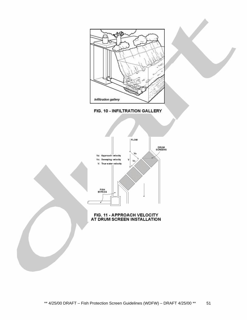
** 4/25/00 DRAFT – Fish Protection Screen Guidelines (WDFW) – DRAFT 4/25/00 ** 51
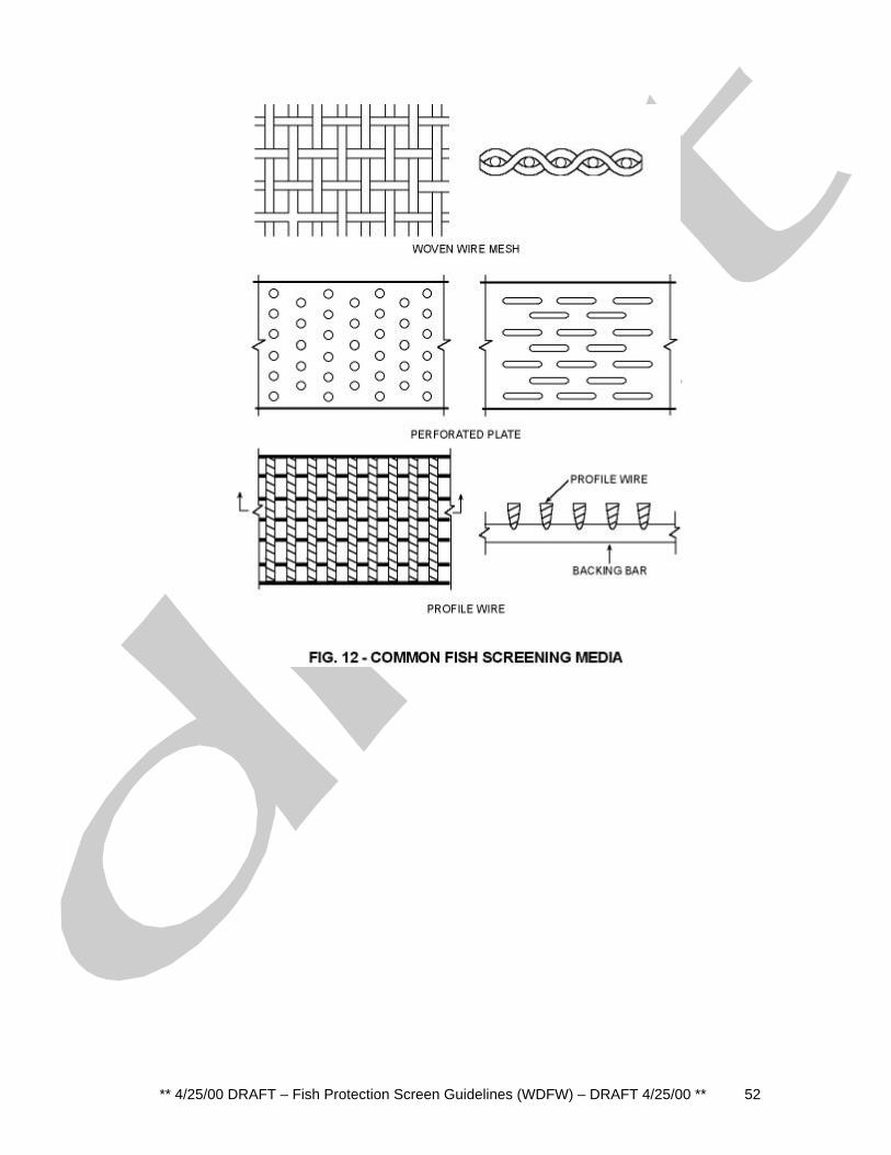
** 4/25/00 DRAFT – Fish Protection Screen Guidelines (WDFW) – DRAFT 4/25/00 ** 52

** 4/25/00 DRAFT – Fish Protection Screen Guidelines (WDFW) – DRAFT 4/25/00 ** 53