fischer core series
TRANSCRIPT

© Fischer Connectors SA – All rights reserved Web version 1.5 - 06.2017 – Changes without prior notice
FISCHER CORE SERIES PLASTIC
TECHNICAL SPECIFICATIONS
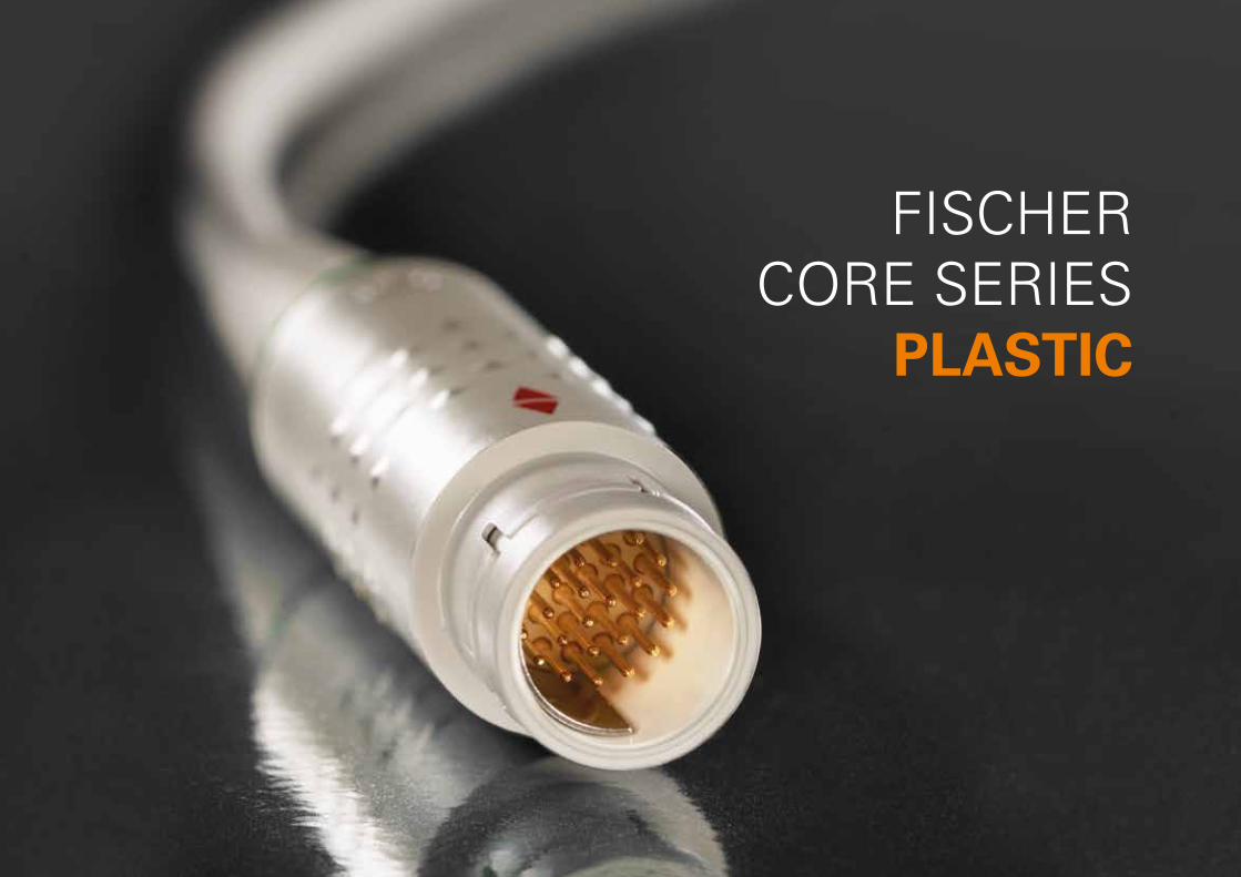
FISCHER CORE SERIES
PLASTIC
PLA
ST
IC
E 1
FISCHER CORE SERIES PLASTIC
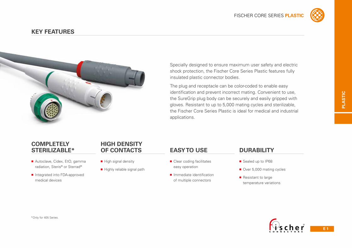
COMPLETELY STERILIZABLE*
■ Autoclave, Cidex, EtO, gamma radiation, Steris® or Sterrad®
■ Integrated into FDA-approved medical devices
■ High signal density
■ Highly reliable signal path
■ Sealed up to IP68
■ Over 5,000 mating cycles
■ Resistant to large temperature variations
■ Clear coding facilitates easy operation
■ Immediate identification of multiple connectors
HIGH DENSITY OF CONTACTS EASY TO USE DURABILITY
Specially designed to ensure maximum user safety and electric shock protection, the Fischer Core Series Plastic features fully insulated plastic connector bodies.
The plug and receptacle can be color-coded to enable easy identification and prevent incorrect mating. Convenient to use, the SureGrip plug body can be securely and easily gripped with gloves. Resistant to up to 5,000 mating cycles and sterilizable, the Fischer Core Series Plastic is ideal for medical and industrial applications.
KEY FEATURES
*Only for 405 Series.
E 2 Technical Specifications
FISCHER CORE SERIES PLASTIC
PLA
ST
IC
Table of contents
405 - PLUGS & RECEPTACLE
CABLE MOUNTED PLUGS ■ Body style selection (S / SI 405) ............................................................E 3
CABLE MOUNTED RECEPTACLE ■ Body style selection (DBP 405) ...........................................................E 3
■ Technical dimensions ................................................................................E 4
■ Part numbering ..........................................................................................E 5
■Electrical & contact configurations .....................................................E 6
■PCB hole pattern pin layout ....................................................................E 7
4032 - PLUG & RECEPTACLES
CABLE MOUNTED PLUG ■ Body style selection (S / SI 4032) .........................................................E 3
CABLE MOUNTED RECEPTACLES ■ Body style selection (DBP/DBPO 4032) ..........................................E 3
■ Technical dimensions ................................................................................E 12
■ Part numbering ...........................................................................................E 13
■Electrical & contact configurations .....................................................E 14
■PCB hole pattern pin layout ....................................................................E 15
FOR ALL PLASTIC 405
■ Accessories ...........................................................................................................................E 8
■ Technical information ..........................................................................................................E 10
■ Cross-line technical information .....................................................................................A 9
FOR ALL PLASTIC 4032
■ Accessories ...........................................................................................................................E 16
■ Technical information ..........................................................................................................E 18
■ Cross-line technical information .....................................................................................A 9
PLA
ST
IC
E 3All dimensions and images shown are in millimeters and are for reference only.
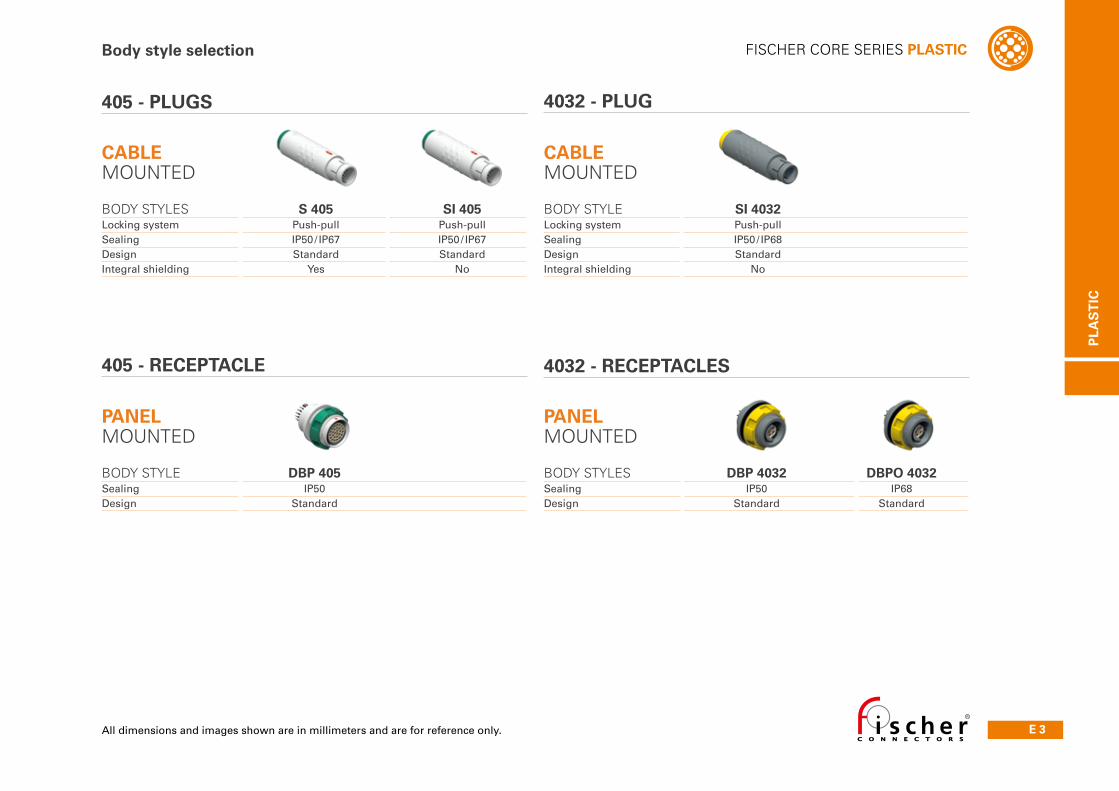
FISCHER CORE SERIES PLASTICBody style selection
PANEL MOUNTED
BODY STYLE DBP 405Sealing IP50Design Standard
PANEL MOUNTED
BODY STYLES DBP 4032 DBPO 4032Sealing IP50 IP68Design Standard Standard
405 - RECEPTACLE 4032 - RECEPTACLES
405 - PLUGS 4032 - PLUG
CABLE MOUNTED
BODY STYLES S 405 SI 405Locking system Push-pull Push-pullSealing IP50/ IP67 IP50/ IP67Design Standard StandardIntegral shielding Yes No
CABLE MOUNTED
BODY STYLE SI 4032Locking system Push-pullSealing IP50/ IP68Design StandardIntegral shielding No
E 4 Technical Specifications
FISCHER CORE SERIES PLASTIC
PLA
ST
IC
All dimensions and images shown are in millimeters and are for reference only.
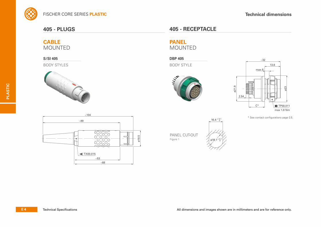
Technical dimensions
405 - PLUGS 405 - RECEPTACLE
CABLE MOUNTED
S/SI 405
BODY STYLES
PANEL MOUNTED
DBP 405
BODY STYLE
~104
~89
~53
~68
ø18
.5
TX00.015
ø23
~32
2.54
C*
13.6
ø21
.9
max 6
max 1.8 Nm
TP00.011
ø18.1
16.4 + 0.1 0
+ 0.1 0
* See contact configurations page E 6.
PANEL CUT-OUT Figure 1

PLA
ST
IC
E 5
FISCHER CORE SERIES PLASTICPart numbering
405S 405 A 087 - B 3 2L R
Body style
■Plug, with integral shielding = S■Plug, without integral shielding = SI■Receptacle, rear panel mounted = DBP
Contact type
■Solder = J■Crimp = K■PCB = L
Insulator material
■PEEK = 3
Body color
■Beige = B■Anthracite = C
Contact configuration
■See page E 6
Series
■405
Contact polarity
■Plugs have pins. Receptacles have sockets = A■Plugs have sockets. Receptacles have pins = Z
Standard options
Color coding
■Anthracite = 2■Green = 3■Blue = 4■Yellow = 5■Beige = 8
Bend relief material
■None = R■Silicone (6.5 dia.) = S■TPE (6.5 dia.) = T■Silicone (3.5 dia.) = U■TPE (3.5 dia.) = W
Housing design
E 6 Technical Specifi cations
FISCHER CORE SERIES PLASTIC
PLA
ST
IC
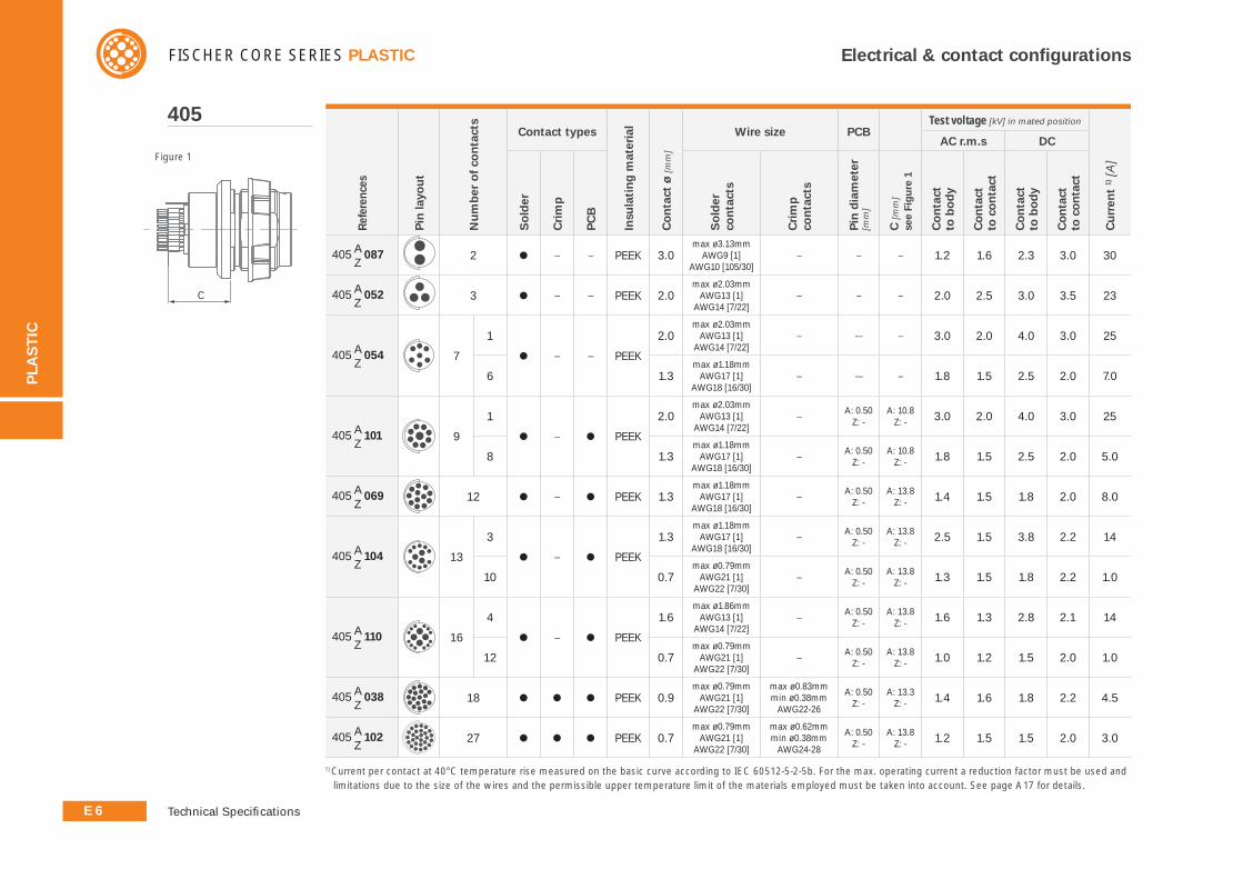
Electrical & contact confi gurations
Ref
eren
ces
Pin
layo
ut
Nu
mb
er o
f co
nta
cts
Contact types
Insu
lati
ng
mat
eria
l
Co
nta
ct ø
[mm
]
Wire size PCBTest voltage [kV] in mated position
Cu
rren
t 1) [
A]
AC r.m.s DC
So
lder
Cri
mp
PC
B
So
lder
co
nta
cts
Cri
mp
co
nta
cts
Pin
dia
met
er
[mm
]
C [m
m]
see
Fig
ure
1
Co
nta
ct
to b
od
y
Co
nta
ct
to c
on
tact
Co
nta
ct
to b
od
y
Co
nta
ct
to c
on
tact
405 A087 Z
2 ● – – PEEK 3.0max ø3.13mm
AWG9 [1]AWG10 [105/30]
– – – 1.2 1.6 2.3 3.0 30
405 A052 Z
3 ● – – PEEK 2.0max ø2.03mm
AWG13 [1]AWG14 [7/22]
– – – 2.0 2.5 3.0 3.5 23
405 A054 Z
7
1
● – – PEEK
2.0max ø2.03mm
AWG13 [1]AWG14 [7/22]
– -– – 3.0 2.0 4.0 3.0 25
6 1.3max ø1.18mm
AWG17 [1]AWG18 [16/30]
– -– – 1.8 1.5 2.5 2.0 7.0
405 A101 Z
9
1
● – ● PEEK
2.0max ø2.03mm
AWG13 [1]AWG14 [7/22]
–A: 0.50
Z: -A: 10.8
Z: - 3.0 2.0 4.0 3.0 25
8 1.3max ø1.18mm
AWG17 [1]AWG18 [16/30]
–A: 0.50
Z: -A: 10.8
Z: - 1.8 1.5 2.5 2.0 5.0
405 A069 Z
12 ● – ● PEEK 1.3 max ø1.18mm
AWG17 [1]AWG18 [16/30]
–A: 0.50
Z: -A: 13.8
Z: - 1.4 1.5 1.8 2.0 8.0
405 A104 Z
13
3
● – ● PEEK
1.3max ø1.18mm
AWG17 [1]AWG18 [16/30]
–A: 0.50
Z: -A: 13.8
Z: - 2.5 1.5 3.8 2.2 14
10 0.7max ø0.79mm
AWG21 [1]AWG22 [7/30]
–A: 0.50
Z: -A: 13.8
Z: - 1.3 1.5 1.8 2.2 1.0
405 A110 Z
16
4
● – ● PEEK
1.6max ø1.86mm
AWG13 [1]AWG14 [7/22]
–A: 0.50
Z: -A: 13.8
Z: - 1.6 1.3 2.8 2.1 14
12 0.7max ø0.79mm
AWG21 [1]AWG22 [7/30]
–A: 0.50
Z: -A: 13.8
Z: - 1.0 1.2 1.5 2.0 1.0
405 A038 Z
18 ● ● ● PEEK 0.9max ø0.79mm
AWG21 [1]AWG22 [7/30]
max ø0.83mmmin ø0.38mm
AWG22-26
A: 0.50Z: -
A: 13.3Z: - 1.4 1.6 1.8 2.2 4.5
405 A102 Z
27 ● ● ● PEEK 0.7max ø0.79mm
AWG21 [1]AWG22 [7/30]
max ø0.62mmmin ø0.38mm
AWG24-28
A: 0.50Z: -
A: 13.8Z: - 1.2 1.5 1.5 2.0 3.0
405
C
Figure 1
1) Current per contact at 40°C temperature rise measured on the basic curve according to IEC 60512-5-2-5b. For the max. operating current a reduction factor must be used and
limitations due to the size of the wires and the permissible upper temperature limit of the materials employed must be taken into account. See page A17 for details.
PLA
ST
IC
E 7All dimensions and images shown are in millimeters and are for reference only.
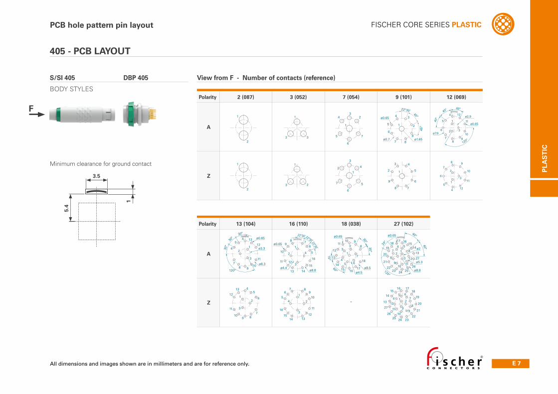
FISCHER CORE SERIES PLASTIC
Polarity 2 (087) 3 (052) 7 (054) 9 (101) 12 (069)
A
Z -
Polarity 13 (104) 16 (110) 18 (038) 27 (102)
A
Z –
4 2
5 7
6
1
31
2 3
1
2
View from F - Number of contacts (reference)
5.4
Minimum clearance for ground contact
1
3.5
1
ø8.8ø4.4
ø0.65
22°30’22°30’22°30’
2
3
4 5
678
9
10
11 12
13 14
15
16
ø4.5ø8.5
ø0.65
23
45 6
7
8910
11
12
13
1415 16
17
18
1
30°30°
15°
60°
ø5.3
ø8.8
ø0.65
ø2
40°
40°
24°
24°
120°
1615
14
13
27
26252423
22
21
20
1918
17
12
3
45
12
1110
9
8
76
1718
19
20
21
22232425
26
13
1415
16
21
3
76
8
910
11
12
45
27
ø0.65
ø7.9
ø2.94
5
6
78
9
10
11
12
40°40°
40°
1
2 3
120°
120°
ø8.3
ø3.3
ø0.6530°
30°
30°
45
6
78 9
11
10
12
13
12
3
45
6
789
11
10
12
13
12
3
1
2
3
45
67 8
9
10
11
121314
15
16
4
5
6
7
8 9
10
11
12
1
2
3
ø0.654
5
6
7 8
9
22°30’
2
3
ø0.7 ø1.65
45°
1
45°
4
5
6
78
9
2
3
1
42
57
6
1
31
23
1
2
405 - PCB LAYOUT
S/SI 405 DBP 405
BODY STYLES
PCB hole pattern pin layout
F
E 8 Technical Specifications
FISCHER CORE SERIES PLASTIC
PLA
ST
IC
Accessories
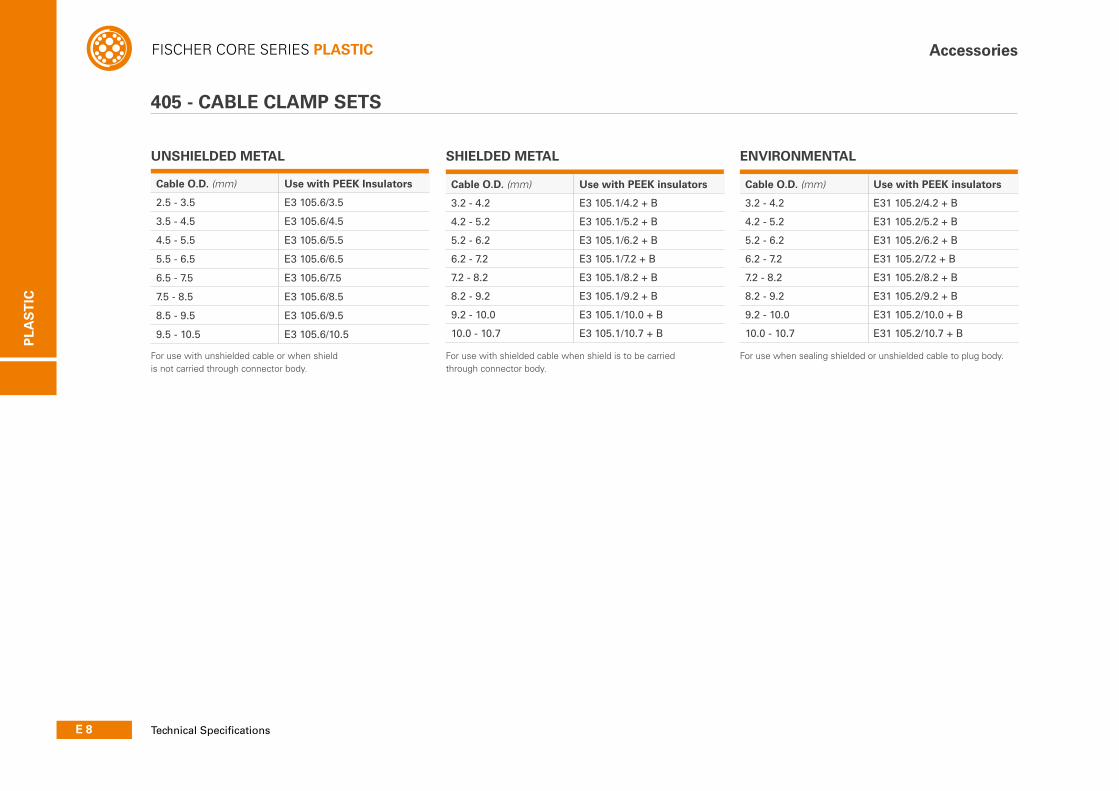
405 - CABLE CLAMP SETS
Cable O.D. (mm) Use with PEEK Insulators
2.5 - 3.5 E3 105.6/3.5
3.5 - 4.5 E3 105.6/4.5
4.5 - 5.5 E3 105.6/5.5
5.5 - 6.5 E3 105.6/6.5
6.5 - 7.5 E3 105.6/7.5
7.5 - 8.5 E3 105.6/8.5
8.5 - 9.5 E3 105.6/9.5
9.5 - 10.5 E3 105.6/10.5
For use with unshielded cable or when shield is not carried through connector body.
Cable O.D. (mm) Use with PEEK insulators
3.2 - 4.2 E3 105.1/4.2 + B
4.2 - 5.2 E3 105.1/5.2 + B
5.2 - 6.2 E3 105.1/6.2 + B
6.2 - 7.2 E3 105.1/7.2 + B
7.2 - 8.2 E3 105.1/8.2 + B
8.2 - 9.2 E3 105.1/9.2 + B
9.2 - 10.0 E3 105.1/10.0 + B
10.0 - 10.7 E3 105.1/10.7 + B
For use with shielded cable when shield is to be carried through connector body.
Cable O.D. (mm) Use with PEEK insulators
3.2 - 4.2 E31 105.2/4.2 + B
4.2 - 5.2 E31 105.2/5.2 + B
5.2 - 6.2 E31 105.2/6.2 + B
6.2 - 7.2 E31 105.2/7.2 + B
7.2 - 8.2 E31 105.2/8.2 + B
8.2 - 9.2 E31 105.2/9.2 + B
9.2 - 10.0 E31 105.2/10.0 + B
10.0 - 10.7 E31 105.2/10.7 + B
For use when sealing shielded or unshielded cable to plug body.
ENVIRONMENTALUNSHIELDED METAL SHIELDED METAL
PLA
ST
IC
E 9All dimensions and images shown are in millimeters and are for reference only.
FISCHER CORE SERIES PLASTIC
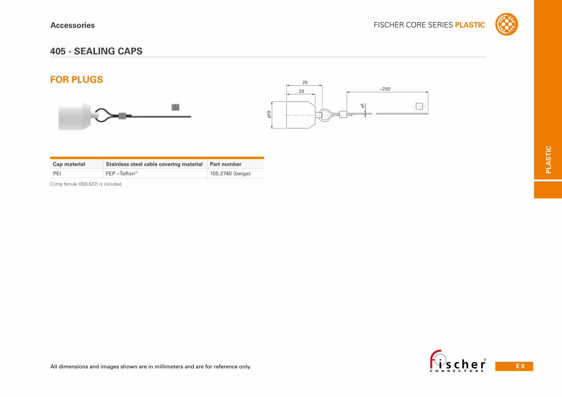
ø1
~25025
20
ø19
Cap material Stainless steel cable covering material Part number
PEI FEP –Teflon® 105.2740 (beige)
405 - SEALING CAPS
Accessories
FOR PLUGS
Crimp ferrule (300.637) is included.
E 10 Technical Specifi cations
FISCHER CORE SERIES PLASTIC
PLA
ST
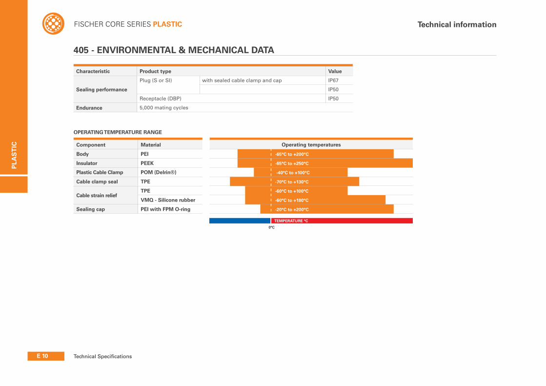
IC Component Material Operating temperatures
Body PEI
Insulator PEEK
Plastic Cable Clamp POM (Delrin®)
Cable clamp seal TPE
Cable strain reliefTPE
VMQ - Silicone rubber
Sealing cap PEI with FPM O-ring
Technical information
Characteristic Product type Value
Sealing performance
Plug (S or SI) with sealed cable clamp and cap IP67
IP50
Receptacle (DBP) IP50
Endurance 5,000 mating cycles
405 - ENVIRONMENTAL & MECHANICAL DATA
OPERATING TEMPERATURE RANGE
0°C
TEMPERATURE °C
-65°C to +200°C
-65°C to +250°C
-40°C to +100°C
-70°C to +130°C
-60°C to +100°C
-60°C to +180°C
-20°C to +200°C
PLA
ST
IC
E 11
FISCHER CORE SERIES PLASTICTechnical information
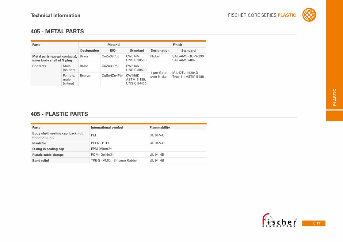
Parts Material Finish
Designation ISO Standard Designation Standard
Metal parts (except contacts), inner body shell of S plug
Brass CuZn39Pb3 CW614NUNS C 38500
Nickel SAE-AMS-QQ-N-290SAE-AMS2404
Contacts Male (solder)
Brass CuZn39Pb3 CW614NUNS C 38500
1 µm Goldover Nickel
MIL-DTL-45204DType 1 + ASTM B488Female,
male (crimp)
Bronze CuSn4Zn4Pb4 CW456KASTM B 139,UNS C 54400
Parts International symbol Flammability
Body shell, sealing cap, back nut, mounting nut
PEI UL 94 V-O
Insulator PEEK - PTFE UL 94 V-O
O-ring in sealing cap FPM (Viton®) -
Plastic cable clamps POM (Delrin®) UL 94 HB
Bend relief TPE-S - VMQ - Silicone Rubber UL 94 HB
405 - METAL PARTS
405 - PLASTIC PARTS
E 12 Technical Specifications
FISCHER CORE SERIES PLASTIC
PLA
ST
IC
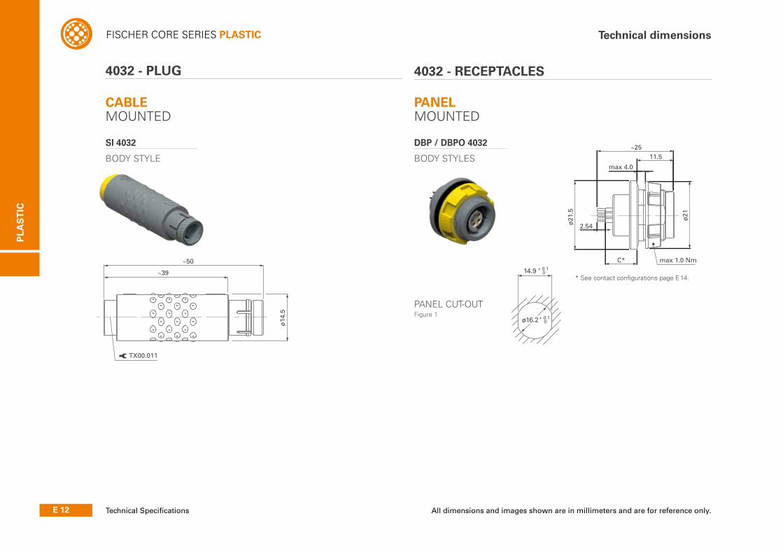
4032 - PLUG 4032 - RECEPTACLES
CABLE MOUNTED
SI 4032
BODY STYLE
PANEL MOUNTED
DBP / DBPO 4032
BODY STYLES
* See contact configurations page E 14.
PANEL CUT-OUT Figure 1
Technical dimensions
~50
~39ø
14.5
TX00.011
~25
max 4.0
ø21
.5
ø21
11.5
C*
2.54
max 1.0 Nm
ø16.2
14.9 + 0.1 0
+ 0.1 0
All dimensions and images shown are in millimeters and are for reference only.
PLA
ST
IC
E 13
FISCHER CORE SERIES PLASTIC
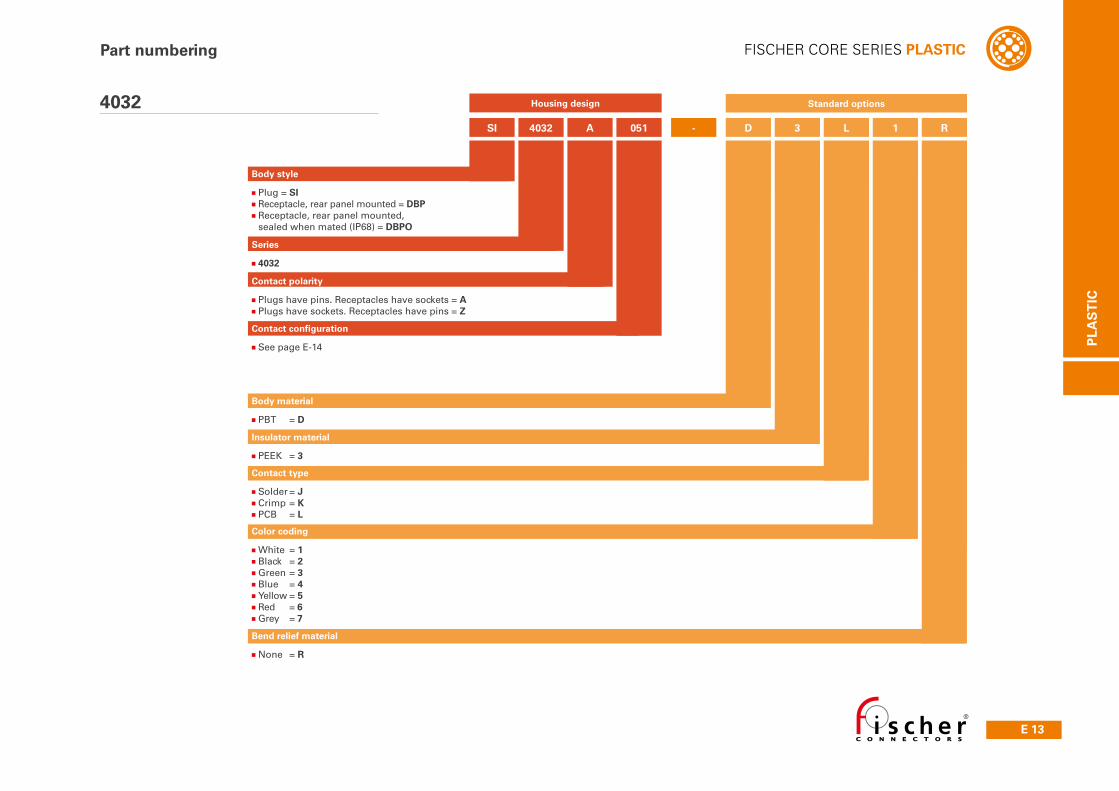
SI 4032 A 051 - D 3 1L R
Body style
■Plug = SI■Receptacle, rear panel mounted = DBP■Receptacle, rear panel mounted, sealed when mated (IP68) = DBPO
Contact type
■Solder = J■Crimp = K■PCB = L
Insulator material
■PEEK = 3
Body material
■PBT = D
Contact configuration
■See page E-14
Series
■4032
Contact polarity
■Plugs have pins. Receptacles have sockets = A■Plugs have sockets. Receptacles have pins = Z
Standard options
Color coding
■White = 1■Black = 2■Green = 3■Blue = 4■Yellow = 5■Red = 6■Grey = 7
Bend relief material
■None = R
Part numbering
4032 Housing design

E 14 Technical Specifi cations
FISCHER CORE SERIES PLASTIC
PLA
ST
IC
Ref
eren
ces
Pin
layo
ut
Nu
mb
er o
f co
nta
cts Contact
types
Insu
lati
ng
mat
eria
l
Co
nta
ct ø
[mm
]
Wire size PCBTest voltage [kV] in mated position
Cu
rren
t 1) [
A]
AC r.m.s DC
So
lder
Cri
mp
PC
B
So
lder
co
nta
cts
Cri
mp
co
nta
cts
Pin
dia
met
er
[mm
]
C [m
m]
see
Fig
ure
1
Co
nta
ct
to b
od
y
Co
nta
ct
to c
on
tact
Co
nta
ct
to b
od
y
Co
nta
ct
to c
on
tact
4032 A 051 Z
2 ● ● – PEEK 1.3max ø1.18mm
AWG17 [1]AWG18 [16/30]
max ø1.18mmmin ø0.58mm
AWG18-24-– – 1.5 2.2 2.2 3.0 13
4032 A 052 Z
3 ● – – PEEK 1.3max ø1.18mm
AWG17 [1]AWG18 [16/30]
– – – 1.2 1.5 1.8 2.0 12
4032 A 053 Z
4 ● – ● PEEK 0.9max ø0.79mm
AWG21 [1]AWG22 [7/30]
–A: 0.63Z: 0.63
A: 9.9Z: 10.0 1.2 1.6 2.0 2.4 7.0
4032 A 054 Z
5 ● ● ● PEEK 0.9max ø0.79mm
AWG21 [1]AWG22 [7/30]
max ø0.83mmmin ø0.48mm
AWG22-26
A: 0.63Z: -
A: 9.9Z: - 1.1 1.4 1.9 2.2 6.8
4032 A 056 Z
6 ● ● – PEEK 0.7max ø0.79mm
AWG21 [1]AWG22 [7/30]
max ø0.62mmmin ø0.38mm
AWG24-28– – 1.0 1.3 2.0 2.0 5.2
4032 A 057 Z
7 ● ● – PEEK 0.7max ø0.79mm
AWG21 [1]AWG22 [7/30]
max ø0.62mmmin ø0.38mm
AWG24-28-– – 1.0 1.3 2.0 2.0 5.0
4032 A 010 Z
10 ● ● ● PEEK 0.7max ø0.79mm
AWG21 [1]AWG22 [7/30]
max ø0.62mmmin ø0.38mm
AWG24-28
A: 0.50Z: -
A: 8.9Z: - 1.4 1.5 2.0 2.2 4.5
4032 A 012 Z
12 ● ● ● PEEK 0.7max ø0.79mm
AWG21 [1]AWG22 [7/30]
max ø0.62mmmin ø0.38mm
AWG24-28
A: 0.50Z: -
A: 8.9Z: - 1.4 1.5 2.0 2.2 4.2
4032 A 019 Z
19 ● ● ● PEEK 0.5max ø0.43mm
AWG26 [1]AWG28 [19/40]
max ø0.43mmmin ø0.20mm
AWG28-32
A: 0.40Z: -
A: 8.9Z: - 1.2 0.9 2.0 1.5 2.5
4032
Electrical & contact confi gurations
C
Figure 1
1) Current per contact at 40°C temperature rise measured on the basic curve according to IEC 60512-5-2-5b. For the max. operating current a reduction factor must be used
and limitations due to the size of the wires and the permissible upper temperature limit of the materials employed must be taken into account. See page A17 for details.
PLA
ST
IC
E 15All dimensions and images shown are in millimeters and are for reference only.
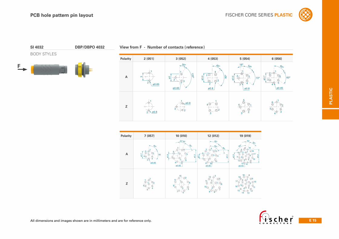
FISCHER CORE SERIES PLASTICPCB hole pattern pin layout
2
ø3.7
ø0.65
7
65
4
3
60°
60°
1 1
ø1.8
ø5.3
ø0.65
22°30’45°
2
3
4
5
6 7
8
9
10
1
ø2.1
ø5.3
ø0.65
ø0.8
2
3
45
6
7
8 910
11
12
60°
40°
40°
1
ø5.6
ø2.9
ø0.55
2
3
4 5
6
7
89
10
11
1213 14
15
16
1718
1960°
15° 30°
2
3
45
6
71
1
2
10
9
8
7 6
5
4
33
2
1
412
11
10
9 87
6
5
16
5
4 3
2
7
1918
17
16
1514 13
12
11
109
8
2
ø3.6
45°
ø0.8
3
41
90°
1
ø3.7
ø0.65
6
54
3
2
60°
60°18°
1
ø3.6
ø0.8
54°
72°5
43
2
1
2
34
5
65
1
23
4
32
14
1ø0.8
32
2
1
ø0.8
2
1
3
ø0.65
30°
1
ø3
ø0.65
23
120°
F
SI 4032 DBP/DBPO 4032
BODY STYLESPolarity 2 (051) 3 (052) 4 (053) 5 (054) 6 (056)
A
Z -
Polarity 7 (057) 10 (010) 12 (012) 19 (019)
A
Z
View from F - Number of contacts ( reference )
E 16 Technical Specifications
FISCHER CORE SERIES PLASTIC
PLA
ST
IC
Accessories
ø1
16.5 ~150
ø16
ø1
~15022
ø16
Ø 3
.2
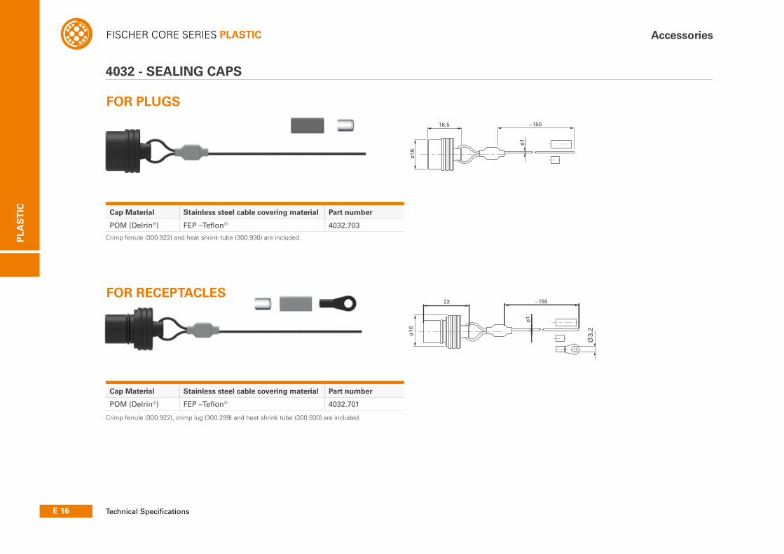
4032 - SEALING CAPS
Cap Material Stainless steel cable covering material Part number
POM (Delrin®) FEP –Teflon® 4032.701
Cap Material Stainless steel cable covering material Part number
POM (Delrin®) FEP –Teflon® 4032.703
FOR PLUGS
FOR RECEPTACLES
Crimp ferrule (300.922) and heat shrink tube (300.930) are included.
Crimp ferrule (300.922), crimp lug (300.299) and heat shrink tube (300.930) are included.
PLA
ST
IC
E 17All dimensions and images shown are in millimeters and are for reference only.
FISCHER CORE SERIES PLASTICAccessories
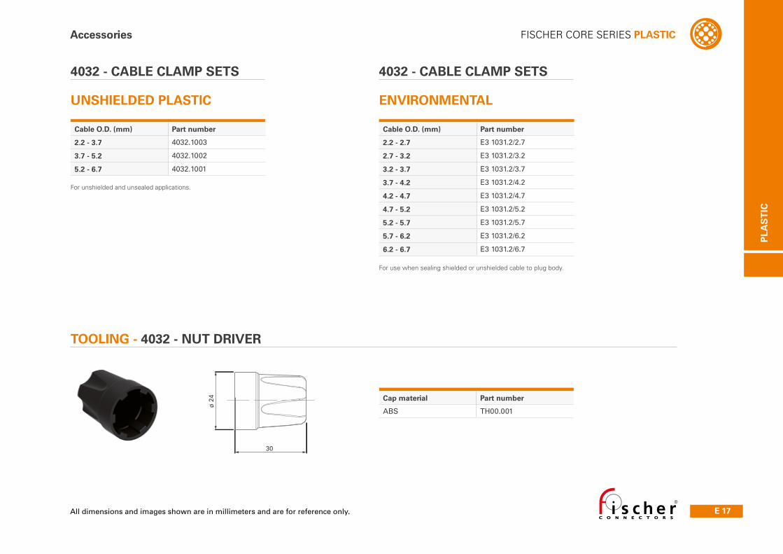
TOOLING - 4032 - NUT DRIVER
4032 - CABLE CLAMP SETS
UNSHIELDED PLASTIC
4032 - CABLE CLAMP SETS
ENVIRONMENTAL
Cable O.D. (mm) Part number
2.2 - 2.7 E3 1031.2/2.7
2.7 - 3.2 E3 1031.2/3.2
3.2 - 3.7 E3 1031.2/3.7
3.7 - 4.2 E3 1031.2/4.2
4.2 - 4.7 E3 1031.2/4.7
4.7 - 5.2 E3 1031.2/5.2
5.2 - 5.7 E3 1031.2/5.7
5.7 - 6.2 E3 1031.2/6.2
6.2 - 6.7 E3 1031.2/6.7
Cable O.D. (mm) Part number
2.2 - 3.7 4032.1003
3.7 - 5.2 4032.1002
5.2 - 6.7 4032.1001
For unshielded and unsealed applications.
For use when sealing shielded or unshielded cable to plug body.
Cap material Part number
ABS TH00.001
ø 2
4
30
E 18 Technical Specifi cations
FISCHER CORE SERIES PLASTIC
PLA
ST
IC
Technical information
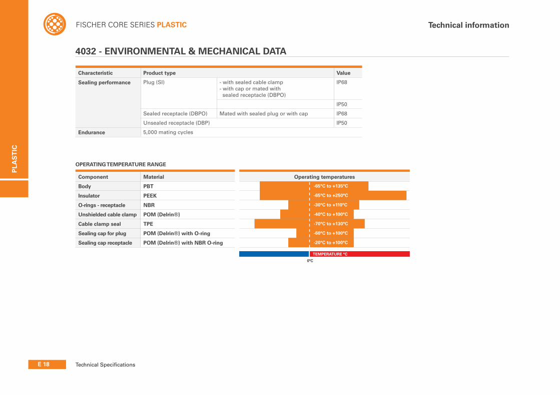
Characteristic Product type Value
Sealing performance Plug (SI) - with sealed cable clamp- with cap or mated with sealed receptacle (DBPO)
IP68
IP50
Sealed receptacle (DBPO) Mated with sealed plug or with cap IP68
Unsealed receptacle (DBP) IP50
Endurance 5,000 mating cycles
Component Material Operating temperatures
Body PBT
Insulator PEEK
O-rings - receptacle NBR
Unshielded cable clamp POM (Delrin®)
Cable clamp seal TPE
Sealing cap for plug POM (Delrin®) with O-ring
Sealing cap receptacle POM (Delrin®) with NBR O-ring
-65°C to +135°C
-65°C to +250°C
-30°C to +110°C
-40°C to +100°C
-70°C to +130°C
-60°C to +100°C
-20°C to +100°C
-30°C to +100°C
4032 - ENVIRONMENTAL & MECHANICAL DATA
OPERATING TEMPERATURE RANGE
0°C
TEMPERATURE °C
PLA
ST
IC
E 19
FISCHER CORE SERIES PLASTICTechnical information
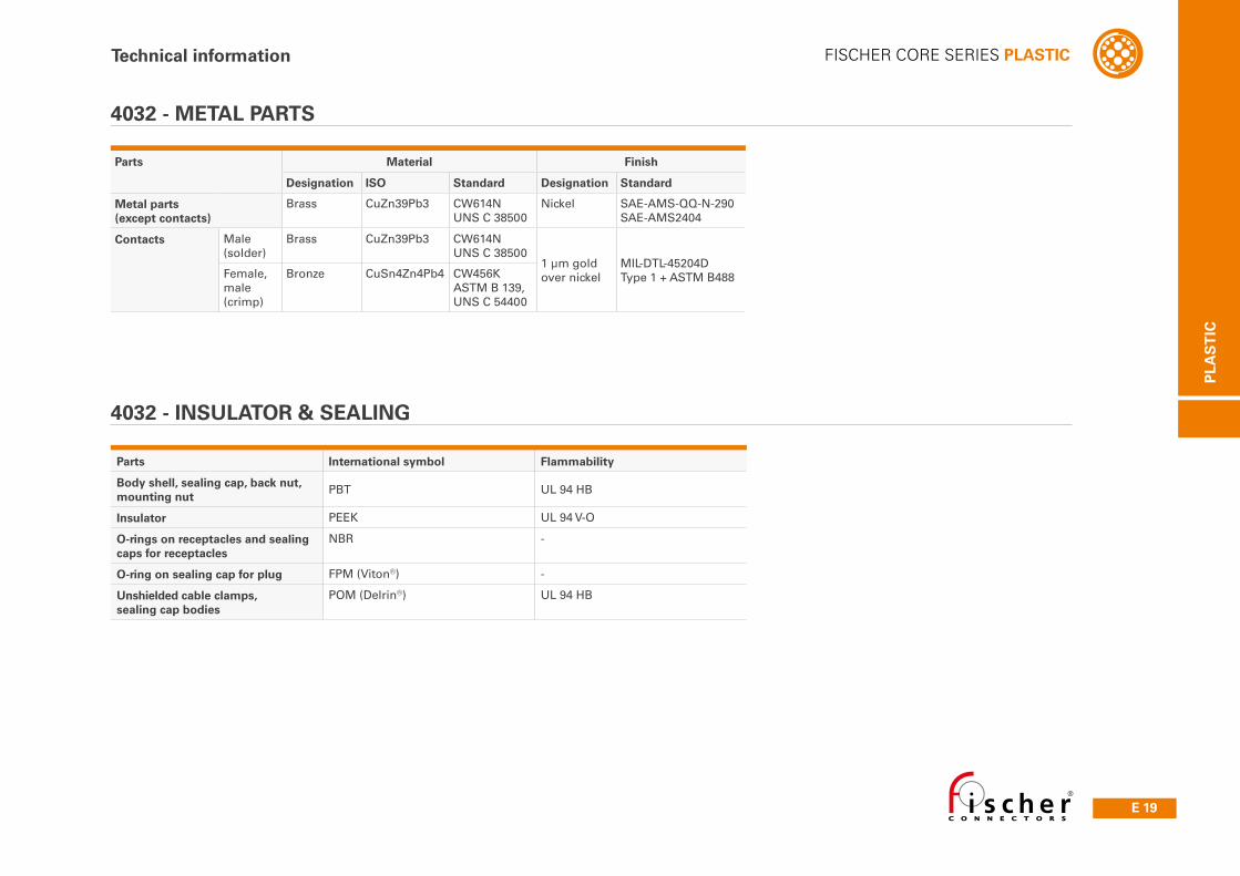
Parts Material Finish
Designation ISO Standard Designation Standard
Metal parts (except contacts)
Brass CuZn39Pb3 CW614NUNS C 38500
Nickel SAE-AMS-QQ-N-290SAE-AMS2404
Contacts Male (solder)
Brass CuZn39Pb3 CW614NUNS C 38500
1 µm goldover nickel
MIL-DTL-45204DType 1 + ASTM B488Female,
male (crimp)
Bronze CuSn4Zn4Pb4 CW456KASTM B 139,UNS C 54400
Parts International symbol Flammability
Body shell, sealing cap, back nut, mounting nut
PBT UL 94 HB
Insulator PEEK UL 94 V-O
O-rings on receptacles and sealing caps for receptacles
NBR -
O-ring on sealing cap for plug FPM (Viton®) -
Unshielded cable clamps, sealing cap bodies
POM (Delrin®) UL 94 HB
4032 - METAL PARTS
4032 - INSULATOR & SEALING